1
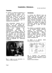
user’s manual 1.0
Safety instructions
WARNING
Before using eo•body, make sure you have read the following instructions carefully, as
well as the instructions for use.
• Do not open or modify eo•body or its main adapter.
• Do not try to repair the interface or the components inside of it.
Please contact eowave for technical support.
• Do not use eo•body nor store it in the following conditions:
- Extreme temperatures, or exposed to direct sunlight.
- Damp areas.
- Dusty areas.
- Areas prone to strong vibrations.
• If you replace the main adapter, make sure its output polarity, voltage and current are
correct.
• Do not insert any objects nor pour any liquid into eo•body.
• Protect eo•body against violent shocks.
• Before using eo•body in a foreign country, make sure the main adapter provided is
compatible with the main supply.
• If eo•body will not to be used for a long period, disconnect the adapter from the main.
• Never place heavy objects on eo•body.
• Never touch eo•body nor the adapter with wet hands when it is plugged in.
• Before moving eo•body, make sure the main adapter and/or any external elements are
disconnected from the unit.
• Before cleaning eo•body, make sure the main adapter is not plugged.
• During ligthning, unplug eo•body.
All trademarks are property of their owners.
user’s manual
•
Congratuations! - Unpacking
Congratulations!
We thank you for choosing eo•body, the essential link between the world of analogue sensors and the digital world of computer processing. The idea of this joint development between Ircam & eowave was to offer the most easy-to-use analogue to MIDI interface for an
affordable price. Of course, other analogue to MIDI converters have already been developped in the past, but none have ever linked simplicity to quality and price like eo•body does.
And indeed, the use of such tools has often been limited or been specially designed for big
projects because of the high cost such installations usually require. eo•body interface is
based on the analogue to MIDI converter Atomic Pro which has been developped by
Emmanuel Flety Ph.D. & engineer at Ircam. With this high-end embedded technology,
eo•body offers high quality data processing, including subsampling and internal filtering
capabilities.
This manual was written by Emmanuelle Gallin
and proof read by Emmanuel Fléty
eowave
7, rue Rouvet
75019 Paris - France
tel.: +33/1 40 05 17 18
fax: +33/1 40 05 00 11
info@eowave.com
sales@eowave.com
www.eowave.com
Ircam
1, place Igor-Stravinsky
75001 Paris - France
tel: +33/1 44 78 49 62
fax: +33/1 44 78 43 55
admin-forum@ircam.fr
Unpacking
Your eo•body package should include the following items. Make sure everything is in the box.
• eo•body
• an AC/DC adapter 9 V/500 mA (European standard plug)
• one pigtail cable D-SUB 15 to 8 Jack plugs 1/4“/ 6,35 mm
• a CD containing:
- the user’s manual
- a free editor for Mac (OS9 and OSX)
- examples of objects and patches for use within Max.
• a registration card
Write down the serial number of your eo•body for future reference!
#
manual ©eowave/Ircam 2003
3
Who’s Who
•
user’s manual
Who’s Who
Ircam
Ircam was founded as a place that combines scientific research, development of related
technologies and contemporary musical creation, for the benefit of the musical and scientific communities. One of the main goals is to contribute, through science and technology, to
the renewal of musical expression. Reciprocally, specific problems related to contemporary
creativity have lead to original steps in the scientific field, with theoretical, methodological
and applied aspects. One of the main links between research and the musical production
activities is done through the development of software environments for composition, that
integrate models and prototypes which come from research teams working in various fields
related to music: computer science (languages, human-computer interface, realtime, database management), digital signal processing, acoustics, psycho-acoustics and cognitive
psychology of audition. Knowledge and tools are also applied to fields of activity in the
industry that go far beyond contemporary musical production.
« At Ircam, my work is mainly oriented towards the design of electronic hardware for stage
and live performance applications. The aim of this design is to provide composer sand performers new tools for expression and control in order to communicate with the computers
involved in computer assisted compositions and musical piece interpretation (sound processing, sound synthesis, sample triggering, spactialization…).
One of those tools is AtoMIC Pro (Analogue to MIDI Converter). This device digitizes analogue signals from sensors to transmit them to the computer which might use those information as a «vision» of the outer world, so our five senses do. Thus stimulated, the machine can «answer» and take certain decisions depending on what happens on stage. This tool
is very useful in the field of interactive sound and/or video installations where it is possibly
needed, for instance, to detect a person at the key place in order to trigger a sound sample,
or to measure the activity in a room to control the volume of a sound effect. »
Emmanuel Fléty, Ircam.
eowave
« eowave was founded in 2002. Since 1998, we have designed our first products under the
name of More Electronic Sounds. We have started with the development of software and
stepped on hardware design of analogue machines and midi tools. There is not such a big
gap between developing software and hardware: both are a subjective representation of the
definition of the sound process. I really enjoyed developing iSynth. With the Essential
Instruments from Cycling’74’s Pluggo 3, each module is dedicated to a special synthesis:
granular, additive synthesis, FM, an analogue modeling synth or a wavetable synth… I have
tried to extract the essential of synthesis, starting all over again with fundamental questions:
«what’s an FM synthesis & how should it be concretized?» Now, some analogue effects I
have designed - the little analogue effects called the «bugs» for example - can be viewed as
some kinds of hardware Essential Instruments. Several little boxes, each representing an
effect, a multimodal filter, a ring modulator, a phaser or a sequencer. Several little boxes any
musician can use to add an analogue feeling to his music… Several easy-to-use little boxes
which can be used alone or assembled to create new sounds. But aside the search for new
tools, and new ways of expression is a real quest among unknown dimensions. The world
of synthesis is immense, while the world of expression has no limits. At this frontier comes
eo•body, an ideal intermediate between the external audio and video environment and the
artist, the essentiel bridge linking the world of analogue sensors to the world of digital process. »
Marc Sirguy, MESI/eowave CEO.
4
manual ©eowave/Ircam 2003
user’s manual
•
Table of contents
Table of contents
Safety instructions
2
Congratulations! & Unpacking
3
Who’s Who:
4
Ircam, eowave
I - Sensors & new ways of expressions
6
II - General Overview
8
Description (Front view, Rear view)
9
III - First steps
Power eo•body, Connect a sensor to eo•body, Basic Configuration, Connect eo•body
to your computer, Use two eo•body or more, Reset eo•body to factory settings
IV - Use eo•body editor
12
Install eo•body editor, eo•body editor menus, first step with eo•body editor, eo•body
editor Window, eo•body Input windows1-8 & 9-16, (Status, Resolution, Zoom & Offset,
Type (Control change / CC, Note on message / N-ON trigger, Program change / PC,
Pitch bend / PB, Polyphonic Aftertouch / Atp, Monophonic Aftertouch / Atm), Channel,
Gate , S Samp Val 1, Prm1, Prm2), Configuration map for analogue inputs, Knobs &
Switches Window (Type, Channel, Value), Configuration example
Appendices
1 - Maximal Voltage Range for global scaling
21
2 - Example of a Sysex configuration of an eo•body preset 22
3 - Making my own sensors
24
Making my own sensor switch, Making my own sensor potentiometer, Making my
own sensor with other kinds of sensors, Analogue Input Connections (D-SUB
15 Wiring, Jack 1/4“ - 6,35 mm, Jack plug 1/4“ - 6,35 mm)
4 - List of MIDI Controllers
26
5 - MIDI Implementation Chart
27
Technical specifications
28
eo•body Development Team, Thanks, Contacts & support
29
manual ©eowave/Ircam 2003
5
I - Sensors & new ways of expression
•
user’s manual
I - Sensors
& new ways of expression
From the Idea…
Men have always dreamt of new ways of communication. Through ages, men have thought
of their body as a tool of communication. And indeed, when communicating, this is not only
your voice, nor the only expression in your face that transmits a message, but your entire
way of being. This is your entire body which projects you inside the individual world of one
another. In all cultures, men have developped new ways of communication through dance,
music, art. And still in a matter of a better communication, men have always worked to
improve the interaction between men and machines, thus since the very beginning of
mechanics and later, electronics. More and more, the body has become the cornerstone of
interactive systems of communication. New technologies widen the range of controls. And
controls have entered everyday’s life without us noticing. Remote controls are everywhere:
we control TV, we control VCRs, DVDs, stereos, ovens, climates, windows, garage doors…
Control surfaces are everywhere. Faced to art, control appears to be the new way of expression of this early millenium. Many artists are looking for new ways of expression, of conceptualizing ideas… In this perspective, sensors open new dimensions of expression. eo•body
is the key link between the world of analogue sensors and digital systems.
…To the Realization
The need of new technologies to control the sound has increased with the development of
interactive sound installations and interpretation of musical pieces requiring interfaces other
than traditional instruments. eo•body is the intermediate you need to connect sensors of
any kind (faders, mechanical pressure sensors, piezo electric sensors, infrared barriers,
intruder detector/passive IR sensors, temperature sensors, etc.) to a musical MIDI environment (sequencer, computer, sampler…). eo•body does not impose the sensor type and features portability and versatility. It can be used for sound synthesis control with the jMax environment (Real time team), PD or Max/MSP. As another example, eo•body can also be used
for the control of a MIDI/digital audio sequencer with an original and completely new user
interface.
The MIDI digital code allows to transmit many different data sources. It is known for the
transmission of music notes but other sources such as light, pressure, temperature, speed
or electromagnetic field can be transcoded via MIDI. Considering this, the field of applications of MIDI becomes much wider… All you need is a powerful analogue to MIDI converter
like eo•body and sensors of your choice. As a sensors to MIDI interface meaning to simplify the design of new gestural controllers or interactive sensor-based sound installations,
eo•body converts analogue signals generated by sensors to MIDI messages which will be
received by a sound generator and used to control parameters such as volume, panoramic,
reverberation… The MIDI messages coding the gestures act directly on the sound, turning
the whole system into a new kind of musical instrument. eo•body will transmit the sensors
signal to the computer under digital form, through the MIDI standard. eo•body is fully compatible with any kind of devices featuring a MIDI interface (MIDI port) and makes a real bridge between the analogue world of sensors and digital audio control by gestures. Don’t limit
yourself: eo•body can convert to MIDI up to 16 sensors!
6
manual ©eowave/Ircam 2003
user’s manual
•
I - Sensors & new ways of expression
Internal process
MIDI
input
Analogue inputs
Parameters
Non volatile
memory
Multiplexer
10 bit A/D
converter
7 bit
conversion
MIDI
message
MIDI
ouput
10 bit SYSEX
message
manual ©eowave/Ircam 2003
7
•
II. General overview
user’s manual
II - General Overview
Front view
a
b
f
a
b
c
d
e
f
g
h
i
j
k
l
m
c
f
Powerplug status LED:
MIDI out LED:
MIDI in LED:
[1-8]:
[9-16]:
Buttons A, B, C, D:
Potentiometers 1, 2, 3:
Inputs [1-8]:
Inputs [9-16]:
Maximal voltage:
MIDI in:
MIDI out:
9V DC power plug
d
g
e
g
g
f
f
lights up when plugged & when receiving valid SysEx data
lights up when sending MIDI messages
lights up when receiving MIDI messages
serigraphy for inputs 1 to 8
serigraphy for inputs 9 to 16
free assignable MIDI buttons
free assignable MIDI potentiometers
D-Sub connector 1 for the inputs 1 to 8
D-Sub connector 2 for the inputs 9 to 16
trimmer to set the maximal voltage range (see Appendix 1)
MIDI in plug for receiving SysEx data from a computer
MIDI out plug for sending MIDI data to your remote device
to be connected to the 9 V/500 mA power supply
(European standard plug)
Rear view
h
8
manual ©eowave/Ircam 2003
i
j
k
l
m
user’s manual
•
III - First steps
III - First steps
III.1.
Power eo•body
Connect a 9 V DC / 500 mA power plug into the power plug connector of eo•body. The red LED
lights up when eo•body is well connected. An internal fuse is activated when not plugged right.
220V or 110 AC
/ 9V DC adapter
Mains
220V - 110V AC
9V DC
-
III.2.
+
Connect a sensor to eo•body
female 1/4“ jack
to connect to the sensors
D-SUB 15 pigtail cable
To be connected to eo•body input 1-8 or 9-16
A pigtail D-sub cable is delivered with eo•body. The D-SUB connector may be plug either
on the female D-SUB connector 1 for the inputs 1 to 8 or to the female D-Sub connector 2
for the inputs 9 to 16. Each of the 8 female 1/4’’ jacks from the pigtail cable may be connected to male 1/4’’ jack cable from a sensor.
Additional pigtails are available thru eowave.
manual ©eowave/Ircam 2003
9
•
III.3. - First steps
III.3.
user’s manual
Basic Configuration
Basic configuration to control a MIDI expander with eo•body
Plug the eo•body MIDI out to the MIDI expander MIDI in.
MIDI cable
MIDI expander
MIDI in
Audio
amplifier
MIDI out
Mixing desk
Sensors
III.4.
Connect eo•body to your computer
To connect eo•body to your computer, plug the eo•body MIDI out to the MIDI interface MIDI
in from your computer. Plug the eo•body MIDI in to the MIDI interface MIDI out from your
computer.
computer with
eo•body editor
MIDI
interface
and other audio
software
MIDI cables
analogue signal
USB, serial
or sound card
with MIDI port
SENSOR
10
manual ©eowave/Ircam 2003
USB, Firewire or
internal soundcard
audio
signal
user’s manual
III.5.
•
III.5. - First steps
Use two eo•body or more
When using two eo•body, these units should be connected in parallel to the MIDI interface.
It means that the MIDI interface requires 2 MIDI IN and 2 MIDI OUT ports. eo•body has no
merging function. Therefore, two units cannot be connected in serial (but both eo•body on
a unique MIDI IN and OUT using a MIDI merger). If you need more than 2 eo•body, use as
many different MIDI ports as the number of eo•body units.
Our choice not to use merging capabilities was determined by our will to keep a 100% accurate data flow. Unfortunately, MIDI merging may be the source for losing informations provoking undesirable treatment delays. When using two MIDI ports, the delay generated will
always be equal to the use of 16 active inputs, thus with 32 or more active inputs. The computer will merge data without losing information nor generating additional delays.
MIDI cables
MIDI
interface
MIDI
port 1
computer with
eo•body editor
and other audio
software
SENSOR
MIDI
port 2
USB, serial
or sound card
with MIDI ports
SENSOR
analogue signal
III.6.
Reset eo•body to the factory settings
Should the eo•body need a factory reset, follow these instructions:
- On powering up the eo•body, press the A & B buttons.
> the red LED should flicker.
- Press now the D button.
> The red LED should flicker faster.
- Power down the eo•body.
> The eo•body is reset to factory setting (i.e. controlers 1 to 7 on channel 1).
manual ©eowave/Ircam 2003
11
IV. - Use eo•body Editor
•
user’s manual
IV - Use eo•body editor
IV.1.
Install eo•body editor
For Mac only
For now, eo•body editor is a Macintosh application only. A PC version will be developped in
the nearest future.
Installation
For MacOS 9, you need OMS 2.3.8 installed in your computer.
Insert the eo•body CD delivered in the CD player from your computer. Move the eo•body
folder on your hard disc. It contains one stand-alone application. Double-click on the icon
to open it.
For Maxers
If you are a Max/MSP user, you may use the collective file to avoid two Max applications running on the same computer.
IV.2.
eo•body editor menus
File Menu
Open, Save, Save as : opens, save and save as eo•body presets. Presets can be stored.
They may be recall for a specific configuration.
MIDI Setup : Open the MIDI configuration setup.
Function Menu
Dump : Send a preset to eo•body
Request : Request a preset from eo•body
Inputs 1-8 : Open configuration window
Inputs 9-16 : Open configuration window
Switchs & knobs : Open switches & potentiometers configuration window
12
manual ©eowave/Ircam 2003
user’s manual
IV.3.
•
IV.3. - Use eo•body Editor
First step with eo•body editor
When opening eo•body editor window, no parameters are set. To modify the configuration
from eo•body, you may first transfer its memory into the editor or recall a preset configuration already stored on your hard drive. To proceed to this transfer, you need a bi-directional
MIDI connection with the MIDI out from your computer connected to the MIDI in from
eo•body & the MIDI out from eo•body connected to the MIDI in from the computer. Ensure
that you are using the same port on eo•body.
The «request» button from the editor enables to send a message to eo•body to dump
eo•body ’s memory. eo•body ’s memory contains will be dumped and its information will be
displayed on the 1-8 Inputs Window, 9-16 Inputs Window or Knobs & Switches Window.
You may proceed to the modification from your configuration in two steps :
First, modify the parameters from your configuration directly on the editor. Secondly, dump
your new configuration into eo•body.
Once the modifications are stored, you may test your configuration with the Input Monitor
Window from the eo•body editor : each bargraph shows the activity from each input.
Note : 10 bits data are not represented by the Input Monitor Window.
Once tested, unplug eo•body ’s connection from the computer.
eo•body has a non-volatile memory. You may also store your configurations onto your hard
drive & recall them when desired.
manual ©eowave/Ircam 2003
13
IV.4. - Use eo•body Editor
IV.4.
•
user’s manual
eo•body editor window
Main editor window
Dump file to eo•body’s memory
Select MIDI port
(MIDI in and out must
be on the same port)
Request a file from
eo•body’s memory
Open the configuration
window for analogue
inputs 9 to 16
Open the configuration
window for analogue
inputs 1 to 8
Open the configuration
window for switches and
potentiometers
Information about activity
of the 16 analogue inputs
Information about type of
controller coming in
patch name
The main editor window offers one pop-up menu and 5 buttons: dump, request, 1-8, 9-16
and knobs.
14
midi port menu
enables to choose the transmission and reception port.
Transmission and reception port has to be the same.
dump
dump a configuration/set up to eo•body
request
request the current configuration/set up from eo•body
1-8
opens the configuration window for inputs [1-8]
9-16
opens the configuration window for inputs [9-16]
knobs
opens the configuration window «knobs & switches» for the setting of the
4 switches and the 3 potentiometers from the front panel of eo•body.
Input monitor
gives information of what’s coming in. 16 bars represent the data which
are being sent from analogue inputs. More accurate information will also
appear on the last line from the window.
Patch name
shows the name of the patch.
manual ©eowave/Ircam 2003
user’s manual
•
IV.5. - Use eo•body Editor
eo•body input windows 1-8 & 9-16
IV.5.
The whole IV.5. part applies to both input windows 1-8 and 9-16, substitute inputs 9-16
to 1-8 where necessary.
Resolution
Offset
Channel
Zoom
Type
Status
Gate
Sub sampling
Parameter 1
Value 1
Parameter 2
With this window, you may set the inputs 1 to 8 from eo•body. Inputs 1 to 8 use a D-SUB
connector.
Status
The status field indicates whether the signal on an analogue input
should be converted into a MIDI message or not. This field may be set
to ON or OFF. If the field is set to OFF, the input is said to be inactive
and no MIDI message relating to that input will be generated, even if
a signal does physically enter the device. If the field is switched back
to ON, the input is active and its associated MIDI message will be sent
each time the signal connected to that input varies in level.
on/off
Note:
The smaller the number of active inputs is, the higher the acquisition frequency of the active inputs will be.
Resolution
Sets the resolution for sent data.
7 bits generates information from 0 to 127. This information format is
used by most common hardware & software MIDI devices.
10 bits generates information from 0 to 1023. This is a more accurate
format but can only be used to send pitch bend or CC data with
MSB/LSB (Most Significant Bits/Least Significant Bits). MSB/LSB can
only be used with softwares like Max/MSP, Jmax or PD.
Note about the high resolution:
• For the pitch bend message, the 10 bits of the sampled value are mapped on the ten most significant bits of the MIDI message which actually counts 14 bits.
• For the control change message, the 3 Most Significant Bits (MSB) are sent via the Prm1 controller
number whilst the «normal» controller number exports the 7 Least Significant Bits (LSB). To obtain the
10 bit value, the following calculation must be computed: 10 bit value = (MSB controller value X 128)
+ LSB controller value. A Max/PD Abstraction is avalaible on the CD. See «Combine Ctr».
manual ©eowave/Ircam 2003
15
•
IV.5. - Use eo•body Editor
Zoom & Offset
user’s manual
Those two parameters specify how the real range of an analogue
input can be mapped on a seven bit MIDI value. As a matter of fact, a
sensor does not necessarily have a range equal to the reference voltage of the Analogue to Digital Converter. We have implemented a
custom scaled zoom on the digital value to take advantage of the 10
bit resolution of the A/D converter. First, the voltage reference has to
be set to the largest range among the sensors connected to the unit.
Then, the user can select the sensor’s range within the 10 bits dynamic by specifying a window size and an offset. The selected range can
then be converted into 7 bits MIDI data without greatly increasing the
quantification step, as shown in the following illustration.
Zoom:
max/mid/low/off
Offset: 0 to 895
(depending on
zoom level)
Digital value
(10 bits)
MIDI data
(7 bits)
1023
MIDI conversion
zoom setting
=
real sensor range
127
Offset
0
Type
This is one of the most important configuration parameters, since it
determines which type of MIDI message the device is going to send
in response to variations in a particular analogue input. eo•body is
capable of generating 6 different messages:
•
•
•
•
•
•
Control Change
CC
16
manual ©eowave/Ircam 2003
CC:
Note:
PC:
PB:
ATp:
ATm:
Control number change (Control change)
Note on Trigger
Program change
Pitch bend (Variation in pitch)
Polyphonic aftertouch (Polyphonic pressure)
Monophonic aftertouch (Channel pressure)
This is the type of message which will likely be most often
used for controlling sound parameters. The value of the analogue signal acts directly upon the value of a MIDI controller, using a
MIDI controller Value Change message (control change). The number
of the controller can be set by the user. If 10 bits resolution is selected, this message will actually send two Control Change messages.
The controller specified in the val field will send the 7 least significant
bits whilst the controller specified in the prm1 field will send the 3
most significant bits, on the same MIDI channel.
user’s manual
•
IV.5. - Use eo•body Editor
Note on message
The analogue signal must correspond to an envelope changing with time and which has a maximum value. You will
have to specify 3 parameters, note sent, higher treshhold, lower treshhold. eo•body analyses this envelope: once the envelope has reached
the higher treshhold, a MIDI note on message (NOTE ON) is generated.
The velocity associated with the note is fixed to 127. The note number
contained within the message is adjustable by the user. As long as the
envelope stays above a threshold, named NOTE OFF threshold, the
note is maintained (no new MIDI message is sent). When the level falls
beneath the NOTE OFF threshold, a MIDI NOTE OFF message is sent
to turn the note off. To sustain the note for a long period of time, you
just need to give a small value to the NOTE OFF threshold. Conversely,
to make the note stop shortly after the peak has been detected, you
need to set the NOTE OFF value quite large. This type of message is
useful in using sensors to generate MIDI notes.
N-ON trigger
Signal
NOTE ON message
NOTE ON
threshold
NOTE OFF message
NOTE OFF
threshold
t
NOTE ON
t
NOTE OFF
t
Program Change message
PC
Pitch bend
PB
The analogue signal must correspond to an
envelope changing with time and which has a
maximum value. You will have to specify 3 parameters, Program
Change sent, higher treshhold, lower treshold. eo•body analyses this
envelope: once the envelope has reached the higher threshold, a MIDI
Program Change message is generated. The Program Change contained within the message is adjustable by the user. As long as the envelope stays above a threshold, named lower threshold, the Program
Change is maintained (no new MIDI message is sent). When the level
falls beneath the lower threshold, the eo•body is ready to receive a
new Program Change message.
This message allows an analogue signal to generate a MIDI message
of the pitch change type (pitch bend). Pitch is usually coded over 14
bits. If the 7 bits resolution is chosen, they will be mapped on the 7
most significant bits of pitch information controlled by the analogue
signal. However, since eo•body does 10 bits conversions internally,
the whole 10 bits can be mapped to take better advantage of the pitch
bend message. This message is used to simulate the pitch changing
wheels available on most MIDI keyboards.
Polyphonic Aftertouch
ATp
This message allows an analogue signal to generate a polyphonic pressure type MIDI message (polyphonic aftertouch). The number of the note to which the pressure
information is applied can be changed by the user.
manual ©eowave/Ircam 2003
17
•
IV.5. - Use eo•body Editor
user’s manual
Monophonic Aftertouch
This message allows an analogue signal to generate a channel pressure type MIDI message
(channel aftertouch). This pressure message affects a whole MIDI
channel, regardless of what note is played. The channel number to
which the pressure information is applied is selected by the user.
ATm
Channel
This field enables the user to select a MIDI channel to which the MIDI
message will apply (1 to 16).
MDI Channel: [1-16]
Gate
The noise gate threshold specifies the variation of the analogue signal
that would be detected as a change. If the analogue signal moves
inside the range of the noise gate, no MIDI message will be sent. This
field enables the user to set the width of the range. A large range will
be very effective against strong noise but will make the MIDI value
less sensitive to a relevant change of the analogue signal. For a reference voltage of +5V a threshold of 8 corresponds to a noise level of
± 40 mV (ie: the analogue has to change at least of 40 mV above or
under its current position to be detected as changing). A threshold of
127 corresponds to a ribbon of ± 620 mV of noise.
Noise Gate: [0-127]
Sensor
Noise band
Sensor signal
2* (noise)
0
S Samp
subsamp
Val 1
val: 0 - 127
18
manual ©eowave/Ircam 2003
Sampled value
Sampled value
+MIDI message
t
This field enables the user to adjust the subsampling filter. SUBSAMP
is a subsampling filter (also called downsampling filter). It will make
eo•body analyse the analogue input not every scan cycle.
Thus, fast changes on the signal will not be detected resulting a lowpass filter. The number of «wasted cycles» is configured in the Nb
Cycles field.
This field enables the user to set the fixed parameter of a MIDI message associated with an analogue input. This parameter value may
correspond to a MIDI note number, a MIDI controller number or a MIDI
program number, depending on the type of MIDI message which is
chosen.
user’s manual
Prm1
•
IV.6. - Knobs and Switches window
This field enables the user to configure the note on activation level for
trigger messages or for the MSB controller number.
multipurpose
parameter #1
0 - 127
Prm2
Same as Prm 1, depending on what type of MIDI information are sent.
multipurpose
parameter #2
0 - 127
Configuration map for analogue inputs
Type of message
Res.
Val1
Prm1
Prm2
CC
- Control Change
7 bits
CC value
CC
- Control Change
10 bits
CC MSB
CC LSB
Note - Note on trigger
7 bits
note number
higher threshold lower threshold
PC
- Program Change
7 bits
PG value
higher threshold lower threshold
PB
- Pitch Bend
7 bits
PB
- Pitch Bend
10 bits
ATp - polyphonic aftertouch
7 bits
ATm - monophonic aftertouch
7 bits
IV.6.
note number
Knobs & Switches Window
Enables to set the 4 switches and the 3 potentiometers from the front panel of eo•body.
Note that switches and potentiometers do not transmit the same kind of information.
Switches transmit Control Change messages, Note On, Note Off, Pogram Changes.
Potentiometers transmit Control Change messages, Pitch Bend, Polyphonic Aftertouch,
Monophonic Aftertouch.
manual ©eowave/Ircam 2003
19
IV.7. - Configuration example
Type
•
user’s manual
This is one of the most important configuration parameters, since it
determines which type of MIDI message the device is going to send
in response to variations in a particular analogue input. eo•body is
capable of generating the messages as follow.
Applicable to switches:
• CC: Control number change (Control change)
• Note: Note on Trigger
• PC: Program change
Applicable to potentiometers:
•
•
•
•
CC:
PB:
ATp:
ATm:
Control number change (Control change)
Pitch bend (Variation in pitch)
Polyphonic aftertouch (Polyphonic pressure)
Monophonic aftertouch (Channel pressure)
For the description of these parameters, see the IV.2 eo•body input
windows 1-8 & 9-16 section.
Channel
This field enables the user to select a MIDI channel to which the MIDI
message will apply (1 to 16).
Ch: [1-16]
Value
Val: 0-127
IV.7.
This field enables the user to set the fixed parameter of a MIDI message associated with an analogue input. This parameter value may
correspond to a MIDI note number, a MIDI controller number or a MIDI
program number, depending on the type of MIDI message which is
chosen.
Configuration example
To set Controller #1 on channel 1 from eo•body using input 1, with a pedal for example.
1.
2.
3.
4.
5.
6.
7.
8.
9.
10.
11.
12.
13.
14.
15.
20
Connect eo•body to your computer
Open eo•body Editor, press the «request» button from the editor, open 1-8 Inputs
Window & configure input 1 parameters
Set status on
Select 7 bit
Set zoom off - offset will be automatically disactivated
Select type CC
Select channel 1
Open gate on 8
Set subsampling on 0
Set val1 to 1
Prm1 & Prm2 are not used in this configuration
DUMP
Plug the 1/4’’ jack from the foot pedal into the female 1/4’’ jack from the channel 1
of the pigtail cable.
Start playing with the foot pedal. The green bargraph from the main editor window
should follow your moves.
The sensor (foot pedal) is now ready to be used within other applications. Once set
so, you don’t need the eo•body editor anymore.
You may unplug eo•body from your computer.
manual ©eowave/Ircam 2003
user’s manual
•
Appendix 1 / Maximal voltage range
Appendices
1 - Maximal Voltage Range for global scaling
The trimmer position enables to set the maximal analogue voltage before conversion to digital. It means that analogue signal from 0 to 5 Volts will be converted into digital values from
0 to 1024. Some sensors may have a range from 0 to 4 Volts. To get the maximal digital
range, the trimmer should be adjusted to 4 Volts. Note that voltage references value below
2.5V may increase sensitivity to noise.
Analogue
signal
Digital
value
5V
1023
2,5V
512
Range
0
t
Signal 1
Signal 2
When the Maximal Voltage Range is set under the maximal voltage from the sensor, the
signal may clip and some information may be lost. Always ensure that the reference voltage
is set to the maximum range of the connected sensors.
Reference
voltage
Digital
value
Dead areas
1023
5V
3V
maximum range of the signals
0
Analogue signals
manual ©eowave/Ircam 2003
21
•
Appendix 2 / SYSEX
user’s manual
2 - Example of a Sysex configuration of an eo•body preset
The whole sysex file has to be sent at one time
To modify parameters, values from row 3 for the switches, from row 4 for the
potentiometers, from row 6 to 23 for imputs 1 to 16 need to be adjusted.
0,
1,
2,
3,
4,
5,
6,
7,
8,
9,
10,
11,
12,
13,
14,
15,
16,
17,
18,
19,
20,
21,
22,
‘eoprogram ‘;
240 0 32 57 64 127;
0 8 0 0;
1 0 1 0 1 0 2 0 1 0 3 0 1 0 4 0;
1 0 5 0 1 0 6 0 1 0 7 0;
0 0;
0 0 8 0 0 8 1 0 0 0 0 0 3 0 0 0 0 0;
0 0 8 0 0 8 2 0 0 0 0 0 3 0 0 0 0 0;
0 0 8 0 0 8 3 0 0 0 0 0 3 0 0 0 0 0;
0 0 8 0 0 8 4 0 0 0 0 0 3 0 0 0 0 0;
0 0 8 0 0 8 5 0 0 0 0 0 3 0 0 0 0 0;
0 0 8 0 0 8 6 0 0 0 0 0 3 0 0 0 0 0;
0 0 8 0 0 8 7 0 0 0 0 0 3 0 0 0 0 0;
0 0 8 0 0 8 8 0 0 0 0 0 3 0 0 0 0 0;
0 0 8 0 0 8 9 0 0 0 0 0 3 0 0 0 0 0;
0 0 8 0 0 8 10 0 0 0 0 0 3 0 0 0 0 0;
0 0 8 0 0 8 11 0 0 0 0 0 3 0 0 0 0 0;
0 0 8 0 0 8 12 0 0 0 0 0 3 0 0 0 0 0;
0 0 8 0 0 8 13 0 0 0 0 0 3 0 0 0 0 0;
0 0 8 0 0 8 14 0 0 0 0 0 3 0 0 0 0 0;
0 0 8 0 0 8 15 0 0 0 0 0 3 0 0 0 0 0;
0 0 8 0 0 8 0 1 0 0 0 0 3 0 0 0 0 0;
247;
program name (for internal use of the editor only)
header tag (not to be changed)
empty informations for further use
switch configuration
potentiometer configuration
empty informations for further use (not to be changed)
input 1 configuration
input 2 configuration
input 3 configuration
input 4 configuration
input 5 configuration
input 6 configuration
input 7 configuration
input 8 configuration
input 9 configuration
input 10 configuration
input 11 configuration
input 12 configuration
input 13 configuration
input 14 configuration
input 15 configuration
input 16 configuration
Footer tag (not to be changed)
Switches and potentiometers use the same parameters
Switch configuration 4 x 2 bytes for switches A, B, C, D
Potentiometer configuration 3 x 2 bytes for potentiometers 1, 2, 3
channel C (0-15, type of information X (0-5), value 0 0 (0-127, in 8 bits on 2 bytes)
CX00
Example:
Controller 1 on Channel 1: 0 0 1 0
Controller 64 on Channel 16: 15 0 0 4
Type of information
0
1
2
3
4
5
CC
Note On Trigger
Program Change
Picht Bend
Polyphonic After Touch
Monophonic After Touch
An entire sequence for pots will be
Example CC 1 to 3 on Channel 1
4, 0 0 1 0 0 0 2 0 0 0 3 0;
22
manual ©eowave/Ircam 2003
user’s manual
•
Appendix 2 / SYSEX
Configuration of inputs 1 to 16 is the same for each input
6, 0 0 8 0 0 8 1 0 0 0 0 0 3 0 0 0 0 0 example of input 1
status ON, 7 resolution, zoom off, offset O, type CC, Channel 1, Gate 8,
Subsamp 0, Val1 1, Prm 1 0, Prm2 0
All parameters in 8 bit format on 2 bytes except for the offset in 14 bits on two 8
bits values (MSB/LSB)
Note: some
1
2
3
4
5
6
7
8
9
parameters are coded on the same bit
00
subsampling
00
gate + resolution (gate + 128 for 10 bits, gate + 0 for 7 bits)
0
MIDI Channel
0
Type of controller +status ON/OFF (Type + 8 for ON, Type + 0 for OFF)
00
Value 1 (0-127)
00
Prm 1 (0-127)
00
Prm 2 (0-127)
00
Zooming (0-3) - (0 is max, 3 is off)
0 0 0 0 offset in 14 bits only the first 10 bits are used
A code which is directly sent to eo•body will be like:
240 0 32 57 64 127 0 8 0 0 15 0 0 4 0 0 2 0 1 0 3 0 1 0 4 0 0 0 1 0 0 0
200030000080081000003000000080082000
003000000080083000003000000080084000
003000000080085000003000000080086000
003000000080087000003000000080088000
0 0 3 0 0 0 0 0 0 0 8 0 0 8 9 0 0 0 0 0 3 0 0 0 0 0 0 0 8 0 0 8 10 0 0
0 0 0 3 0 0 0 0 0 0 0 8 0 0 8 11 0 0 0 0 0 3 0 0 0 0 0 0 0 8 0 0 8 12 0
0 0 0 0 3 0 0 0 0 0 0 0 8 0 0 8 13 0 0 0 0 0 3 0 0 0 0 0 0 0 8 0 0 8 14
0 0 0 0 0 3 0 0 0 0 0 0 0 8 0 0 8 15 0 0 0 0 0 3 0 0 0 0 0 0 0 8 0 0 8
0 1 0 0 0 0 3 0 0 0 0 0 247
manual ©eowave/Ircam 2003
23
•
Appendix 3 / Making your own sensors
user’s manual
3 - Making my own sensors
eo•body supports many kind of sensors. Most common sensors are switches and potentiometers, but there are many other kinds of sensors.
Making my own sensor switch
Switch
3-5 Kohm
ground
+ 5V
(to avoid antenna effect
when the switch is off)
Signal
Sensors need a minimum of two cables: ground and signal. When 5 V is connected to the
signal - when using switches for example - it may create an antenna effect generating undesirabled distorsion. This is the reason why the signal must be connected to the ground.
Making my own sensor potentiometer
Potentiometer
+ 5V
ground
Signal
To use a standard potentiometer with eo•body, connect both outputs of the potentiometer
resistor to the ground and 5 V. Connect the variable output of the potentiometer to the signal
input.
Making my own sensor with other kinds of sensors
Coming from eo•body or external
power supply (any other voltage has to
come from an external power supply)
+ 5V or + 9V
Sensor
ground
ground
Signal
Some sensors like distance sensors need an extra power supply. eo•body delivers +5V and
+9V to power these sensors up to 250 mA. When the total consumption from all the sensors
plugged to eo•body is higher than 250 mA, an additional external power supply is necessary.
24
manual ©eowave/Ircam 2003
user’s manual
•
Appendix 3 / Making your own sensors
Some sensors have a weak signal out and need amplifying. To avoid undesirable noises,
the amplifier should be placed as close as possible from the sensor.
Connection cable
NOISE
Sensor
eo•body
amplifier
GOOD
d1
d2
Connection cable
NOISE
Sensor
eo•body
amplifier
BAD
d1
d2
d1<<d2
Analogue Input Connections
D-SUB 15 Wiring
1.
2.
3.
4.
5.
6.
7.
8.
signal
signal
signal
signal
signal
signal
signal
signal
1
2
3
4
5
6
7
8
9.
10.
11.
12.
13.
14.
15.
gnd
gnd
gnd
gnd
+5V
+5V
+9V
8 7 6 5 4 3 2 1
pin 15
pin 1
+9V
+5V
Ground
Jack 1/4“ - 6,35 mm
ground
+5V
signal
Jack plug 1/4“ - 6,35 mm
Tip:
+5V
Ring:
signal
Sleeve: ground
manual ©eowave/Ircam 2003
25
•
AppendiX
user’s manual
4 - List of MIDI Controllers
N°
Function
0
1
2
3
4
5
6
7
Bank Select
0-127 MSB
Modulation wheel
0-127 MSB
Breath control
0-127 MSB
Undefined
0-127 MSB
Foot controller
0-127 MSB
Portamento time
0-127 MSB
Data Entry
0-127 MSB
Channel Volume
0-127 MSB
(formerly Main Volume)
Balance
0-127 MSB
Undefined
0-127 MSB
Pan
0-127 MSB
Expression Controller 0-127 MSB
Effect control
0-127 MSB
Effect control
0-127 MSB
Undefined
0-127 MSB
Undefined
0-127 MSB
General Purpose
0-127 MSB
Controler
Undefined
0-127 MSB
Bank Select
0-127 LSB
Modulation
0-127 LSB
Breath control
0-127 LSB
Undefined
0-127 LSB
Foot controller
0-127 LSB
Portamento time
0-127 LSB
Data entry
0-127 LSB
Channel Volume
0-127 LSB
(formerly Main Volume)
Balance
0-127 LSB
Undefined
0-127 LSB
Pan
0-127 LSB
Expression Controller 0-127 LSB
Effect control 1
0-127 LSB
Effect control 2
0-127 LSB
Undefined
0-127 LSB
Undefined
0-127 LSB
General Purpose
0-127 LSB
Controller (1-4)
Undefined
0-127 LSB
Damper pedal
≤63=off ≥64=on
on/off (Sustain)
8
9
10
11
12
13
14
15
16-19
20-31
32
33
34
35
36
37
38
39
40
41
42
43
44
45
46
47
48-51
52-63
64
26
manual ©eowave/Ircam 2003
Value
N°
Function
65
66
67
68
69
70
Value
Portamento on/off
Sustenuto on/off
Soft pedal on/off
Legato footswitch
Hold 2
Sound Controller 1
(Sound Variation)
71
Sound Controller 2
(Timbre)
72
Sound Controller 3
(Release Time)
73
Sound Controller 4
(Attack Time)
74
Sound Controller 5
(Brightness)
75
Sound Controller 6
76
Sound Controller 7
77
Sound Controller 8
78
Sound Controller 9
79
Sound Controller 10
80-83 General Purpose
Controller (5-8)
84
Portamento Control
85-90
91
92
93
94
95
96
97
98
Undefined
Effect 1 Depth
Effect 2 Depth
Effect 3 Depth
Effect 4 Depth
Effect 5 Depth
Data entry +1
Data entry -1
Non registered
Parameter Number
99
Non registered
Parameter Number
100
Registered
Parameter Number
101
Registered
Parameter Number
102-119 Undefined
120-127 Mode messages
≤63=off ≥64=on
≤63=off ≥64=on
≤63=off ≥64=on
≤63=off ≥64=on
≤63=off ≥64=on
0-127 LSB
0-127 LSB
0-127 LSB
0-127 LSB
0-127 LSB
0-127
0-127
0-127
0-127
0-127
0-127
LSB
LSB
LSB
LSB
LSB
LSB
0-127 Source
Note
0-127 LSB
0-127 LSB
0-127 LSB
0-127 LSB
0-127 LSB
0-127 LSB
N/A
N/A
0-127 LSB
LSB
0-127 LSB
MSB
0-127 LSB
LSB
0-127 LSB
MSB
user’s manual
•
Appendix 5 / MIDI implementation chart
5 - MIDI Implementation Chart
Function… Transmitted Recognized
Remarks
Basic Channel
Default
changed
* 1-16
* 1-16
X
X
Mode
default
Messages
Altered
Mode 3
X
X
X
X
X
Note Number
True Voice
* 0-127
* 0-127
X
X
Velocity
NOTE ON
NOTE OFF
1-127
64
X
X
After Touch
Key
Channel
o
o
X
X
Pitch Bender
o
X
10 bit resolution
Control Change
* 0-127
X
memorised
Program Change
* 0-127
X
Program
number 1-128
System Exclusive
o
o
System Common Song Pos
Song Sel
Tune
X
X
X
X
X
X
System Real time Clock
Commands
X
X
X
X
AUX Messages
X
X
X
X
X
X
X
X
Local ON/OFF
All Notes OFF
Active Sense
Reset
Mode 1: OMNI ON, POLY
Mode 3: OMNI OFF, POLY
Mode 2: OMNI ON, MONO
Mode 4: OMNI OFF, MONO
memorised
memorised
o: Yes
X: No
manual ©eowave/Ircam 2003
27
•
Technical specifications
user’s manual
Technical specifications
Dimensions:
Width
Depth
High
182 mm
128 mm
38 mm
(knobs high excluded)
Weight:
580 g
Impedancy:
1 MΩ
Latency:
around 200 µs by active in,
A/D conversion added excluding MIDI message
980 µs per control change without running status
640 µs per control change (i.e. 1280 ms for a 10 bits send)
MIDI Message adds:
Running status adds:
Optimise Running status up to 33%:
Keep it on the same MIDI channel (some latency is added by
changing MIDI channel). If you need different MIDI channels,
make sure to group your sensors as follow:
- Sensors 1 to 5, MIDI channel 3
- Sensors 6 to 14, MIDI channel 8
Power consumption:
25 mA under 9V DC, internal diameter of the plug: 2,5 mm
Thermic fuse:
Polyswitch operating at 250 mA
CE norm & FCC INFORMATION
1. Important notice: do not modify this unit!
This product, when installed as indicated in the instructions contained in this manual, is
compatible with the CE norm & FCC requirements.
2. Important!
When connecting this product to accessories and/or another product, use only high quality
shielded cables. Cables supplied with this product must be used. Follow all installation instructions. Failure to follow instructions could void your FCC authorisation to use this product
in the USA.
Note: this product has been tested and found to comply with the requirements listed in FCC
Regulations, Part 15 for Class B digital devices & in The European Standard EN 50081-1 on
Electromagnetic Compatibility - Generic emission standard on residential, commercial and
light industry. Compliance with these requirements provides a reasonnable level of assurance that the use of this product in a residential environment will not result in harmful interference with other electronic devices.
28
manual ©eowave/Ircam 2003
user’s manual
•
Contacts & support
eo•body Development Team
Emmanuel Flety, Ircam (hardware design, micro controller programming, PCB)
Marc Sirguy, MESI/eowave CEO (concept, specs, software, production, distribution)
Emmanuelle Gallin, MESI/eowave manager (executive manager)
Denis Germain, MESI/eowave (graphic design)
Thanks
Many thanks to Bernard Steigler, Ircam Director, to Vincent Puig, Ircam Marketing Director,
for making this cooperation between eowave & Ircam possible, to Paola Palumbo, Ircam
Sales Administration Manager, for her excellent job and her wonderful smile when facing difficulties, to Cyrille Brissot for testing eo•body, to Christophe Martin de Montagu for his support, tips and listening, to Mauriccio Perez for recording performances with talent, to Hélène
Barrier for her artistic improvisation for the first performance ever made with an eo•body…
and to all who have shown their interest since the very beginning of this project.
Contacts & support
eowave
7, rue Rouvet
75019 Paris - France
tel.: +33/1 40 05 17 18
fax: +33/1 40 05 00 11
info@eowave.com
sales@eowave.com
www.eowave.com
Ircam
1, place Igor-Stravinsky
75001 Paris - France
tel: +33/1 44 78 49 62
fax: +33/1 44 78 43 55
admin-forum@ircam.fr
manual ©eowave/Ircam 2003
29