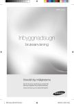
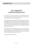
1
AFFINITY™ CUSTOM CHILLER
User Manual D6621
Lydall Industrial Thermal Solutions Inc.
Post Office Box 1000
775 Route 16
Ossipee NH 03864 USA
Telephone: 603-539-3600 (Sales), 603-539-5005 (Service), Fax: 603-539-8484
O:\MANUALS\D6622 REV. B (02/03/2003) NMT
Table of Contents
Introduction
Equipment Precautions
Safety Precautions
Installation
Transporting
Placement
Electrical Requirements
Priming the Pumps and Connecting the Coolant Loop
Pressure Gauges
Filters
Cooling a Water-Cooled Condenser
Operation
Using the Controllers
Programming Values for the Loop 1 Controller
Programming Values for the Loop 2 Controller
Changing the Set-Value Temperature
Safety Alarms (Temperature)
Communications
Other Lights and Switches on the Control Panel
General
Preventive Maintenance
25-Pin Interlock Description
PLC Tables
Table of Contents
Trouble Shooting Guide
Warranty
Refrigeration Diagram
Coolant Flow Diagram
Electrical Schematic
O:\MANUALS\D6623 (11/13/2002)
Introduction
Congratulations on your purchase of an Affinity™ product.
I want to personally welcome you to the Lydall larger family. In October of 2001, Lydall
purchased Affinity Industries, in an effort to expand capability as a Total Thermal Solutions
Provider. Affinity’s chillers and heat exchangers complement Lydall’s existing wide array of
Passive Thermal Solutions, augmenting Lydall’s engineered thermal solutions for use in
appliance, cryogenic, building products, and automotive markets. Our group is market driven as
a formidable thermal solution manufacturer.
Lydall, Inc. is a New York Stock Exchange listed company (NYSE: LDL) headquartered in
Manchester, CT. Our company, with ten operations in the United States, France, one in
Germany, and Sales/Service Offices in Japan and Singapore, is recognized for working with
customers to satisfy their unique thermal solution needs, and for delivering high quality,
innovative products, and exceptional service.
Affinity™ products are high-precision specialty temperature-controlled equipment. The following
product manual is designed to help you realize the full value of your purchase.
We highly recommend that you read this manual in its entirety. The manual will assist your
company with the installation, operation, and routine maintenance of your Affinity™ product.
Please keep this manual readily accessible to operation and service personnel to ensure you
get the most out of our product.
If you have any questions about this model, or have other thermal solution needs, do not
hesitate to call our Sales department (603-539-3600) or the 24/7 Service department (603-5395005).
Thank you for your confidence in our ability to meet and/or exceed your needs and
expectations.
Sincerely,
John Tattersall
Group Vice President
Lydall Industrial Thermal Solutions, Inc.
O:\MANUALS\D3774 (01/11/2002)
Equipment Precautions
Failure to adhere to these precautions will void the warranty and may damage the chiller.
1.
This chiller has been shipped without coolant. Do not run it without connecting the
coolant lines and keeping them filled with appropriate coolant. Never run the pump dry
because it will be quickly damaged without liquid.
2.
Never use coolants which are incompatible with the components in this chiller’s coolant
loop. Some coolants may not damage the coolant loop components, yet may
significantly derate the chiller’s cooling capacity. Never use automotive antifreeze or
other antifreeze containing silicates because silicates will cause the pump seals
to fail. Check with the factory if there are questions about the coolant.
3.
Maximum storage temperature for the unit is 52EC (125EF).
4.
This chiller operates on three phase electricity. Some components are sensitive to
phase sequence. The chiller is designed and wired so that all components will operate
properly if the phase sequence is correct. This unit is protected by a Phase Reverse
Relay, to prevent it from running if the sequence is incorrect. If the chiller fails to start
on installation, a qualified electrical technician should check the relay in the electrical
box. If the light on the relay is not brightly lit, the phase sequence is incorrect. The
technician should switch any two wires external to the chiller. Do not modify the
wiring inside the electrical box.
5.
The chiller is designed for indoor use only. Do not operate the chiller in ambient
temperatures below 7EC (45EF). If the chiller has been exposed to ambient
temperatures below 7EC, allow 24 hours at ambient temperatures above 7EC to warm
the oil in the compressor as well as the refrigerant before operating.
6.
This chiller exhausts the heat it extracts to Facility Water. The Facility Water should
have a temperature of 30EC (86EF) or lower. The Facility Water flow will be controlled
by the water valve at the chiller’s condenser. At maximum, the flow may need to be as
high as four liters (one gallon) per minute for each kilowatt of heat extracted. The
Facility Water pressure should be at between two and seven bar (thirty and one hundred
pounds per square inch).
7.
Routinely inspect the pump inlet strainer located in the reservoir for debris. Turn the
chiller off, then remove and clean the strainer as required to permit free flow of coolant.
Prevent foreign debris from entering the coolant lines while the strainer is removed.
Hint: A plastic sandwich bag may be used to wrap the strainer to contain most of the
debris. Failure to keep the strainer clean will reduce the coolant flow and damage the
pump.
Equipment Precautions
8.
Regularly clean the screen in the assembly at the chiller’s inlet for Facility Water. To
clean, shut off the chiller, close off the supply of Facility Water to the chiller, and remove
the screen. Clean as necessary and reinstall. See Installation for further instructions.
9.
The compressor in this unit has been charged with a Polyolester lubricant. Polyolester
lubricants (POE) will quickly absorb moisture from the ambient surroundings. Since
moisture levels greater than 100 ppm will result in system corrosion and ultimate failure,
it is imperative that compressors, components, containers and the entire system be kept
sealed as much as possible. Lubricants will be packaged in specially designed, sealed
containers. After opening, all the lubricant in a container should be used at once since it
will readily absorb moisture if left exposed to ambient air. Work on systems and
compressors must be carried out with the open time as short as possible. Leaving the
system or compressor open during breaks or overnight MUST BE AVOIDED! Mobil EAL
ARCTIC 22 CC is the preferred Polyolester due to unique additives included in this
lubricant. ICI Emkarate RL 32S is an acceptable substitute if Mobil is not available.
10.
As received, the POE lubricant will be clear or straw colored. After use, it may acquire a
darker color. This merely reflects the activity of the lubricant’s protective additive.
11.
Oil level must not fall below ¼ sight glass
12.
Do not operate the chiller at coolant temperatures above or below it was specified to
deliver.
13.
Do not run the chiller with cooling loads that exceed its factory rated cooling capacity.
14.
Do not operate damaged or leaking equipment.
15.
The chiller must not be transported unless properly protected. Original factory
packaging in good condition or equivalent is required. Request air-ride trucks if
transporting over the road.
16.
Modifying the chiller without express written consent from Lydall will void the warranty.
O:\MANUALS\D6624 (10/23/2002)
Safety Precautions
1.
Heed all warning labels. Do not remove.
2.
Do not operate the chiller with the bonnet removed. The bonnet protects personnel from
rotating parts and hot surfaces and also protects the chiller’s components.
3.
Connect the chiller to a properly fused disconnect box in compliance with the NEC
(National Electric Code) as well as state and local codes for American usage, or local
and national codes for European usage. Maximum fuses must not exceed the maximum
rating found on the serial tag on the electrical box. The voltage, phase, and frequency of
the power source must also match the requirements specified on the serial tag. To
reduce the risk of electric shock:
Do not remove cover of the remote control box (if included). Refer servicing to properly
qualified and licensed personnel.
Disconnect electrical power before opening the electrical box, except for the checking of
the phase reverse relay or phase monitor if included with this unit (phase reverse relays
or phase monitors will never be included in single phase units). Power must be applied
in order for the phase reverse relay or phase monitor to indicate phase sequence.
Do not operate equipment with damaged electric power cords.
Turn off the chiller and disconnect electric power before servicing or moving.
4.
Coolant lines, filters, and other components which connect to the chiller must be capable
of withstanding the maximum pressure that the pump in the chiller can deliver at the
maximum expected temperature.
5.
The coolant loop has not been designed for potable water applications. Do not use the
chiller for potable water. Never hook the water lines of a water-cooled unit to a potable
water source or immerse a hose connected to a potable water source in the reservoir
without providing back flow protection. A loss of pressure in the water source could lead
to a back flow of the fluid in the unit, resulting in a possible contamination of the potable
water source.
6.
Vapors of some alcohol based antifreezes as well as other coolants may cause
explosion if exposed to flame or spark.
7.
Certain antifreezes may be poisonous if ingested.
O:\MANUALS\D3799 (10/03/2002)
Installation
Transporting
An Affinity™ chiller rolls easily on four swivel casters. The brakes must be off on the two
locking casters when moving the unit. Roll the chiller gently to its operating location. The
cushioned casters will help to dampen shock. Lock the casters and lower the leveling feet to
support the units full weight when the unit is in place. If a forklift will be used to carry the chiller,
proceed slowly and carefully to avoid jarring the unit. Insert the forks carefully to prevent
damage to the casters. If the unit will be lifted by crane, use lifting strops and do not cinch the
strops
If the chiller will be shipped, protect it from shock and vibration or the warranty will be void. The
chiller must not be transported unless suitably protected. Original factory packaging in good
condition or equivalent is required. Request air-ride trucks when transporting over land.
Thoroughly drain the coolant lines and blow them dry with low pressure compressed air before
shipping or storing.
Placement
Select a level location near the application, free from dripping or spraying moisture and
excessive dust. Keep the coolant lines short to allow the pump to provide maximum pressure
and flow to the application. If the chiller will be placed more than 25 feet from the application,
call Lydall to discuss placement and how it might affect performance.
Electrical Requirements
Connect the chiller to a properly fused disconnect box in compliance with the NEC (National
Electric Code) as well as state and local codes for American usage, or national and local codes
for European usage. Maximum fuse sizes in the disconnect box must not exceed the maximum
ratings specified on the serial tag of the chiller (found on the electrical box near where the
power cord connects). The voltage, phase, and frequency of the power source must also match
the requirements specified on the serial tag.
Note: Affinity™ models that can operate at either 208-230 volts 60 Hertz or 200-220 volts 50
Hertz have been set at the factory for 200-220 volt operation. If the operating voltage will be
greater than 220 volts, a qualified electrician should remove the red wire from the contactor and
replace it with the orange wire taken from the dummy fuse block. Attach the red wire to the
dummy fuse block as shown in the diagram below. See the unit’s serial tag for the correct
voltage range.
Warning: To reduce the risk of electric shock, do NOT remove cover from the
electrical box. It contains exposed high voltage wires. Refer servicing to qualified
personnel. Disconnect power to the chiller before performing any service.
Installation
Priming the Pumps and Connecting the Coolant Loop
DO NOT RUN THE PUMPS DRY. If the pumps do not establish prime, the pump shaft seals
may overheat and be damaged in less than a minute. Use the following instructions when filling
and assembling the coolant lines to prevent damage to the pump shaft seals. Hint: Before
turning the chiller on, have sufficient clean water or coolant at hand. It will be needed
immediately to make up the supply necessary to fill the coolant loop. The pumps in this unit will
usually self-prime. Follow the instructions below for each loop.
1.
Close the reservoir drain.
2.
Fully open the flow control valve (if included).
3.
Have extra coolant to add as the pump primes and the coolant loop fills.
4.
Fill the reservoir with coolant. Do not fill above the height of the coolant loop connection
fittings or fluid may leak out.
5.
Connect the coolant lines from the application to the FPT (female pipe thread) fittings
near the top of the chiller as follows. Do not over tighten the insert and do not use a
sealant that will lock the male threads to the female threads.
a.
Connect the coolant line coming back from the application to the RETURN fitting.
b.
Connect the coolant line going to the application to the SUPPLY fitting.
Installation
6.
This chiller is equipped with a Phase Reverse Relay. The chiller will not start if the
phase sequence is incorrect. If the chiller fails to start upon installation, have a qualified
electrical technician check the Phase Reverse Relay in the electrical box of the chiller. If
the LED is not brightly lit, the phase sequence is incorrect. The technician should switch
any two of the wires at the incoming power source. Do not change any of the wiring
in the electrical box. Check again for proper phase sequence before proceeding with
these instructions.
7.
When the previous steps are complete, turn the chiller on by placing the ON/OFF/SET
switch in the ON position. Immediately check for flow. If within five seconds no
turbulence is visible in the reservoir or the supply pressure gauge shows no pressure
reading, shut the chiller off by placing the ON/OFF/SET switch in the OFF position. If
flow is established, continue filling until the reservoir level rises to within a few inches of
the top. Do not allow the reservoir to overflow.
8.
If the pump does not establish prime, disconnect the SUPPLY coolant line to vent any
trapped air, reconnect the line, and repeat step 7.
9.
If the pump still does not prime, use the following steps:
a.
Disconnect both coolant lines (have a container handy to catch any overflow from
the RETURN fitting).
b.
Force coolant into the SUPPLY fitting. The fluid will force the air out of the lines
in the chiller and out of the pump head, causing it to escape into the reservoir. If
tap water will be the source of coolant, simply connect the tap water line to the
SUPPLY fitting and turn on the tap. If a source of coolant other than tap water
will be used, elevate the coolant a few feet above the chiller, connect to the
SUPPLY fitting, and let gravity force the air out into the reservoir. Remember to
have a container handy to catch any overflow from the RETURN fitting.
c.
Reconnect the coolant lines and repeat step 7. Stop filling when the reservoir is
full to within a few inches of the top. Do not allow the reservoir to overflow.
A stainless steel mesh strainer attaches to the pump suction port near the bottom of the
reservoir. It can easily be removed for cleaning. First turn the pump off, then pull off the
strainer, rinse it clean, and push it back on. To protect the pump, routinely inspect the strainer
to be sure it is clean and properly attached. Hint: If the strainer is coated with debris, wrap it
with a plastic sandwich bag before pulling it off to keep most of the debris from escaping into the
reservoir.
Pressure Gauges
Two gauges on the unit provide information on the Facility Water Pressure condition. One is
labeled Facility Water In Pre-Strainer, one labeled Facility Water In Post-Strainer. Lydall
suggests that the customer takes a sample reading from these gauges soon after installation.
When the gauge pressure rises well above this sample reading it is time to check and clean the
strainer as instructed in the Maintenance section of this manual.
Installation
Date
Facility Water In Pre-Strainer
Facility Water In Post-Strainer
Filters
The Deionizing Filter Is a full flow filter. (All flow leaving the unit will cycle through the filter.) All
valves are in the vertical position when operating under normal conditions (not changing or
bypassing any filters). To change the deionizing filter, open the bypass (H) top valve and then
close the two bottom valves. After changing the filter, reverse operation. (Open lower valves,
then close top valve.) The other two (micron) filters have normal in-line isolation valves for
changing filters. All handles are in horizontal position when bypassing the filter.
Cooling a Water-Cooled Condenser
Never hook a water-cooled unit to a potable water supply without providing back flow protection.
A drop in pressure in the water supply could cause back flow, resulting in the possible
contamination of the potable water supply.
Water-cooled chillers require Facility Water to cool the condenser during operation. The
amount of flow is controlled automatically by a valve Affinity installs on the condenser.
This unit requires facility water flow of 10 gallons per minute. Facility water temperature should
be between 14 and 26 degrees C. Facility water pressure must be between 35 and 75 psig.
Loop 2 will give the best performance (be more stable) when both loops are in operation.
Connect the Facility Water supply to the "WATER IN" fitting at the bottom of the chiller.
Connect the Facility Water return to the "WATER OUT" fitting. Use connecting lines of the size
shown on the coolant diagram (inside diameter) to reduce pressure loss.
Note: The coolant lines of all water-cooled chillers have been blown dry with low pressure air
before shipping to protect the units from freezing and subsequent damage. This may cause the
condenser to be dry which, in turn, could result in failure to start upon initial start-up (there could
be no water in the condenser to absorb the heat). This is easily corrected by pressing the high
pressure reset switch a few times to initiate flow through the Facility Water side of the chiller.
O:\MANUALS\D6625 (10/03/2002)
Operation
Using the Controllers
This chiller comes with two FUJI ELECTRIC 1/16 DIN PYX temperature controllers, one for
each loop. These controllers are programmable microprocessors, which offers many more
features than will need to be mastered at this point. Two additional controllers are also provided
to display the flow for each loop in gallons per minute.
These controllers come pre-programmed according to the Affinity™ model selected. If some of
the controllers’ additional features become necessary, call Lydall service (603-539-5005) for
technical assistance or consult the FUJI ELECTRIC Instruction Manual.
To power the controllers without powering the chiller, place the ON/OFF/SET switch in the SET
position. The digital display will light up. The number next to PV is the actual process coolant
temperature. The number next to SV is the Set-Value (desired) temperature. Lights next to
OUT1, OUT2, ALM1, and ALM2 may also appear. A light on next to OUT1 (when the switch is
in the ON position) indicates that the chiller is cooling. Both ALM1 and ALM2 are alarms that
are configured differently for different chillers.
Factory Programming Values for the Loop 1 Controller
Press and hold the SEL key to access the parameter menu. Use the arrow keys to change
values. Display will return to PV/SV after about one minute if parameters are not being
changed. Set the following values:
LoCt 3
oUT1 ?
Mod
AT
AUTo
oFF
All parameters user changeable
Cannot be set - anything but 0.0 indicates control output #1 is
energized
Mode - Auto or Manual
Normal control - not auto-tuned
Operation
P
8.0
i
d
Ar
Man
AL1T
AL2T
AL21
A21h
AL22
A22h
Loop
PvT
32
0.0
17 (EC), 30 (EF)
0.0
0000
0021
30 (EC), 85 (EF)
1 (EC or F)
4 (EC), 40 (EF)
1 (EC or F)
0.00
0410 (EC)
0411 (EF)
TF
4.0
SFT 0
Sv-h 41 (EC), 105 (EF)
Sv-L 3 (EC), 38 (EF)
CTrL Pid
dT
0.5
rEv1 norM
Mv-h 100.0
Mv-L 0.0
bUrn 1
STno 1
Proportional band - experimental value for HGMV - record actual
values
Integral time - experimental value for HGMV - record actual values
Derivative time
Anti-reset windup - limits integral range to control overshoot
Manual resetting value (eliminates offset from P-only control)
Alarm 1 type (none)
Alarm 2 type (high & low absolute)
Alarm 2 setpoint 1 (high absolute)
Alarm 2 setpoint 1 hysteresis
Alarm 2 setpoint 2 (low absolute)
Alarm 2 setpoint 2 hysteresis
Loop break detection time (alarms on abnormal input)
100 Ohm RTD, -50 to 100EC, 0.1 degree resolution
100 Ohm RTD, -58 to 212EF, 0.1 degree resolution
Input Filter time in seconds
Process Variable shift
Setpoint Variable high limit
Setpoint Variable low limit
Control type
Not supported - always 0.5
Control output #1 action - reverse for modulating HGV
Manipulated variable (control output) high limit in percent
Manipulated variable (control output) low limit in percent
Output value when input is abnormal (set to -3% when bUrn = 1)
Station number for RS 485 communications
Go through the parameters twice, then set LoCt to 2, some parameters user changeable.
Factory Programming Values for the Loop 2 Controller
Press and hold the SEL key to access the parameter menu. Use the arrow buttons to change
values. Display will return to PV/SV after about one minute if parameters are not being
changed. Set the following values:
LoCt 3
oUT1 ?
Mod
AT
P
AUTo
oFF
6.5
i
d
61
0.0
All parameters user changeable
Cannot be set - anything but 0.0 indicates control output #1 is
energized
Mode - Auto or Manual
Normal control - not auto-tuned
Proportional band - experimental value for HGMV - record actual
values
Integral time - experimental value for HGMV - record actual values
Derivative time
Operation
Ar
Man
AL1T
AL2T
AL21
A21h
AL22
A22h
Loop
PvT
17 (EC), 30 (EF)
0.0
0000
0021
30 (EC), 85 (EF)
1 (EC or F)
4 (EC), 40 (EF)
1 (EC or F)
0.00
0410 (EC)
0411 (EF)
TF
4.0
SFT 0
Sv-h 41 (EC), 105 (EF)
Sv-L 3 (EC), 38 (EF)
CTrL Pid
dT
0.5
rEv1 norM
Mv-h 100.0
Mv-L 0.0
bUrn 1
STno 2
Anti-reset windup - limits integral range to control overshoot
Manual resetting value (eliminates offset from P-only control)
Alarm 1 type (none)
Alarm 2 type (high & low absolute)
Alarm 2 setpoint 1 (high absolute)
Alarm 2 setpoint 1 hysteresis
Alarm 2 setpoint 2 (low absolute)
Alarm 2 setpoint 2 hysteresis
Loop break detection time (alarms on abnormal input)
100 Ohm RTD, -50 to 100EC, 0.1 degree resolution
100 Ohm RTD, -58 to 212EF, 0.1 degree resolution
Input Filter time in seconds
Process Variable shift
Setpoint Variable high limit
Setpoint Variable low limit
Control type
Not supported - always 0.5
Control output #1 action - reverse for modulating HGV
Manipulated variable (control output) high limit in percent
Manipulated variable (control output) low limit in percent
Output value when input is abnormal (set to -3% when bUrn = 1)
Station number for RS 485 communications
Go through the parameters twice, then set LoCt to 2, some parameters user changeable.
Changing the Set-Value Temperature
Change the Set-Value by pressing the (>) key on the controller keypad. SV will change to a
leading zero display. Continue pressing the (>) key until the appropriate digit flashes. Press the
(v) or (w) key on the controller keypad until the digit changes to the desired value. Toggle
through using the (>), (v), and (w) keys to change the appropriate digits until the Set-Value
reads as desired. Continue pressing the (>) key until the last digit flashes. Press the (>) key
one more time and all leading zeroes will extinguish. This locks in the Set-Value temperature.
Caution: Never program in a Set-Value temperature of more than 32EC (90EF) unless this
Affinity™ model is specifically modified to operate at higher coolant temperatures. Never
program in a Set-Value temperature of less than 5EC (40EF) unless a suitable antifreeze is used
as coolant AND the unit is designed to operate at below freezing temperatures.
Operation
Safety Alarms (Temperature)
These controllers have ALM1 and ALM2 lights. ALM2 may or may not operate depending on
the exact model of the PYX controller. The alarm(s) have been preset at the factory to come on
when the temperature of the circulating coolant is above or below the temperature the chiller
has been set to deliver.
The OUT1 light on the controller (when lit) indicates that the refrigerant solenoid valve is open to
allow refrigerant to flow to the heat exchanger. If the light is on most of the time, most of the
chiller’s capacity is being used. If the light is on infrequently, much less than the chiller’s full
capacity is being used.
Communications
Pins 2 and 5 on the 9-pin connector provide RS485 Communications from the controllers.
Other Lights and Switches on the Control Panel
HIGH PRESSURE WARNING/ALARM: Amber
Lights when a high pressure condition
exists in the compressor. A flashing light
indicates a warning and a solid light
indicates an alarm.
COMPRESSOR LOW SUCTION: Amber
Flashing. Activated when the compressor
suction pressure is below setpoint. The
chiller will shut down after a time delay.
LOW REFRIGERANT LEVEL: Amber
Solid when a low refrigerant level is sensed
in the receiver.
COMPRESSOR OVERLOAD: Amber
Flashing. Activated after a 2 second delay
by the current sensor in one of the leads to
the compressor motor when the motor has
been shut down due to excessive
temperature.
PHASE LOSS/REVERSAL: Amber
Solid. Activated when phases of unit need
to be reversed. May happen on initial start
up of unit. If it occurs, switch phases
exterior to unit and power unit again.
LOOP 1 LOW LEVEL: Amber
Solid when a low level condition is sensed
by the flow switch in the Loop 1 reservoir.
Operation
LOOP 2 LOW LEVEL: Amber
Solid when a low level condition is sensed
by the flow switch in the Loop 2 reservoir.
LOOP 1 PUMP OVERLOAD: Red
Solid. Activated when pump amperage
exceeds overload setting. Unit shuts down.
The overload switch will have to be reset to
the “start” position before beginning
operation.
LOOP 2 PUMP OVERLOAD: Red
Solid. Activated when pump amperage
exceeds overload setting. Unit shuts down.
The overload switch will have to be reset to
the “start” position before beginning
operation.
LOOP 1 LOW FLOW: Red
Solid. Activated by the flow switch when the
pump flow falls below setpoint.
LOOP 2 LOW FLOW: Red
Solid. Activated by the flow switch when the
pump flow falls below setpoint.
ALARM RESET SWITCH: Black
Use to cancel an reset any alarm when the
alarm condition has been corrected.
General
This unit requires facility water flow of 10 GPM with facility water temperature between 14-26EC,
and pressure between 35 and 75 psig. The best performance (best stability of Loop 2) is
achieved when both loops are in operation.
O:\MANUALS\D6626 (02/03/2003)
25-Pin Interlock Description
Ground
AR2 Loop 2 Low Flow
CR2 Loop 1 Isolation Valve
CR1 Loop 2 Isolation Valve
Loop 1 Temperature Alarm
Loop 2 Temperature Alarm
AR3 Loop 1 Low Level
AR1 Loop 1 Low Flow
AR5 Refrigerant High Pressure
LOCAL/REMOTE
AR4 Loop 2 Low Level
O:\MANUALS\D6627 (11/12/2002)
Pin 1 is ground
Pins 3 and 4 are closed, pins 2 and 3 are open when the
unit is operating normally. Pins 3 and 4 are open, pins 2
and 3 are closed when an alarm condition exists.
Pins 5 and 20 operate a control relay to CR1. With this
coil energized via a customer supplied 24 Volts DC signal,
the Loop 1 isolation valve opens, allowing flow out of the
unit.
Pins 6 and 20 operate a control relay CR2. With this coil
energized via a customer supplied 24 Volts DC signal, the
Loop 2 isolation valve opens, allowing flow out of the unit.
Pins 7 and 8 are open when the temperature is within the
setpoint range and closed when the temperature is < or >
than the setpoint range.
Pins 9 and 10 are open when the temperature is within the
setpoint range and closed when the temperature is < or >
than the setpoint range.
Pins 12 and 13 are closed, pins 11 and 12 are open when
the unit is operating normally. Pins 12 and 13 are open,
pins 11 and 12 are closed when an alarm condition exists.
Pins 15 and 16 are closed, pins 15 and 14 are open when
the chiller is operating normally. Pins 15 and 16 are open,
pins 15 and 16 are closed when an alarm condition exists.
Pins 18 and 19 are closed and pins 17 and 18 are open
when unit is running normally. Pins 18 and 19 are open
and pins 17 and 18 are closed when an alarm condition
exists
Pins 21 and 22 control the Local/Remote Option
Pins 24 and 25 are closed, pins 23 and 24 are open when
the unit is operating normally. Pins 24 and 25 are open,
pins 23 and 24 are closed when an alarm condition exists.
PLC Input Table
Input
Type
Description
Status OFF
Status ON
0
Auxiliary
Contact
Pump 1 Overload
Overload
No Overload
1
Auxiliary
Contact
Pump 2 Overload
Overload
No Overload
2
Level Switch
Refrigerant Low
Level
Level > Setpoint
Level < Setpoint
3
Spare
N/A
N/A
N/A
4
Pressure
Switch
Low Suction
Pressure
Pressure < Setpoint
Pressure > Setpoint
5
Pressure
Switch
High Discharge
Pressure
Pressure > Setpoint
Pressure < Setpoint
6
Flow Switch
Process Flow Loop
1
Flow < Set-point
Flow > Set-point
7
Level Switch
Loop 1 Low Level
Level > Setpoint
Level < Setpoint
8
Level Switch
Loop 2 Low Level
Level > Setpoint
Level < Setpoint
9
Pressure
Switch
High Pressure
Warning
Pressure < Setpoint
Pressure > Setpoint
10
Selector Switch
Pump 2 ON/OFF
Pump 2 OFF
Pump 2 ON
11
Selector Switch
Pump 1 ON/OFF
Pump 1 OFF
Pump 1 ON
12
Flow Switch
Process Flow Loop
2
Flow < Setpoint
Flow > Setpoint
Spare
N/A
N/A
N/A
15
Auxiliary
Contact
Compressor
Overload
Overload
No Overload
16
Relay
Phase Reverse
Relay
Phase
Loss/Reversal
Normal
17
Switch
Local/Remote
Switch
Local
Remote
18
Reset Switch
Alarm Reset
Normal
Resets Faults
19
Spare
N/A
N/A
N/A
13 -14
O:\MANUALS\D6629 (10/03/2002)
PLC Output Table
Output
Type
Description
Status OFF
Status ON
0
Spare
N/A
N/A
N/A
1
Interlock
Refrigeration
High Pressure
Interlock
No Alarm
Alarm Condition
2
Lamp/Interlock
Loop 2 Low Level
Light
Level > Setpoint
Level < Setpoint
3
Lamp
Loop 1 Low Flow
Light
Flow > Setpoint
Flow < Setpoint
4
Lamp
Loop 2 Low Level
Light
Flow > Setpoint
Flow < Setpoint
5
Contactor
Loop 2 Pump
Contactor
Pump OFF
Pump ON
6
Lamp/Interlock
Loop 1 Low Level
Light
Level > Setpoint
Level < Setpoint
7
Lamp
Combined Alarm
No Alarm
Flashing - Compressor
Overload
Solid - Phase
Loss/Reversal
8
Lamp
Combined
Refrigeration
Alarm
No Alarm
Flash = Low Suction
Pressure
Solid = Low Refrigerant
Level Alarm
9
Lamp
High Discharge
Pressure
No Alarm
Flashing = Warning
Solid = Shutdown
10
Contactor
Loop 1 Pump
Contactor
Off
On
11
Contactor
Compressor
Contactor
Off
On
O:\MANUALS\D6630 (10/03/2002)
Trouble Shooting Guide
Problem
Unit does not
start
Possible Cause
Possible Remedy
No power to unit, breaker tripped
Verify correct power is applied,
close breaker after correcting fault
Low voltage
Check electrical service to unit
Wrong phase sequence
Check phase reverse relay or phase
monitor. If sequence is incorrect,
switch any 2 wires on the incoming
power source
Refrigeration high pressure cut-out
tripped
Manually reset button on pressure
switch after correcting fault
Loose wire
Disconnect power, then check
wiring
Defective contactor or coil
Repair or replace contactor or coil
Loss of refrigerant
Locate and repair leak, then
recharge with type and amount of
refrigerant specified on serial tag
Compressor damaged
Replace compressor - Call Lydall
Unit does not
cool
Compressor internal thermostat
tripped
Allow time for compressor to cool
and automatically reset
Compressor damaged
Replace compressor - Call Lydall
Evaporator damaged
Call Lydall
Microprocessor failure
Replace microprocessor
Facility Water control valve set too
low
Reset Facility Water control valve Call Lydall
Microprocessor programmed
incorrectly
Reprogram microprocessor - Call
Lydall
Insufficient flow of Facility Water
Increase flow of Facility Water
Problem
Unit does not
cool
(continued)
Pump leaks
Excessive
noise on StartUp
Possible Cause
Possible Remedy
Facility Water too warm
Provide cooler Facility Water
Cooling load exceeds capacity of
unit
Reduce cooling load
Refrigeration solenoid coil failure
Replace solenoid coil
Loss of refrigerant
Locate and repair leak, then
recharge with type and amount of
refrigerant specified on serial tag
Solid State Relay failure
Replace Solid State Relay
Solenoid valve stuck shut
Repair or replace solenoid valve
Defective refrigeration low pressure
cut-out
Repair or replace low pressure cutout
Malfunctioning thermal expansion
valve
Replace thermal expansion valve
Pump damaged, loss of flow
Replace pump
Hot gas bypass valve setting too
high
Call Lydall
Hot gas bypass valve stuck open
Repair or replace valve
Faulty pump casing
Replace pump assembly
Shaft seal damaged
Replace shaft seal
Pump housing O-Ring damaged
Remove pump and rebuild
Improper fluid
Call Lydall
Low voltage
Check electrical service to unit
Wrong voltage taps used on
transformer
Connect to proper taps
Contactor or coil failure
Replace contactor or coil
Problem
Pump motor
overheats
Noisy
compressor
Level light
remains on
Fault light
remains on
Level light does
not work
Possible Cause
Possible Remedy
Pump overload protection set too
high
Reset pump thermal overload relay,
or replace if faulty
Improper voltage supplied
Correct voltage
Flooding of refrigerant into
crankcase
Warm crankcase if unit has been off
for a long period or has been left in
a cool ambient for more than a few
hours
Worn compressor
Replace compressor - Call Lydall
Refrigeration high pressure cut-out
set too high
Adjust setting
Refrigeration low pressure cut-out
set too low
Adjust setting
Low coolant level
Check for leaks, then fill reservoir
Reservoir level switch float stuck
Clean reservoir and level switch
Time delay relay malfunction (when
used)
Replace time delay relay
Level switch failure
Replace level switch
Low coolant flow
See Problem; Low coolant flow
No coolant flow
See Problem; No coolant flow
Flow switch sticking
Disassemble flow switch, clean and
reinstall, or replace
Time delay relay has not timed out
(when used)
Wait for time delay relay to time out
Lamp burned out
Replace lamp
Level switch failure
Replace level switch
Problem
Low coolant
flow
No coolant flow
Possible Cause
Possible Remedy
Pump suction strainer clogged
Remove strainer, clean and reinstall
or replace
Flow control valve not fully open
Open flow control valve
Pressure relief valve set too low
(unless not adjustable)
Adjust pressure relief valve to
specification
Low coolant level in reservoir
Fill reservoir to proper level
Restriction in coolant lines external
to chiller
Eliminate restrictions in coolant
lines external to chiller
Frozen evaporator
Call Lydall
Flow switch clogged
Disassemble flow switch, clean and
reinstall, or replace
Pump not primed
Prime pump
Pump suction strainer clogged
Remove and clean strainer, then
reinstall
No coolant in reservoir
Repair any leaks, then fill reservoir
Pump overload tripped
Wait 5 minutes for overload to reset
Pump motor shaft bound to seal
Replace pump or renew seal
Pump housing improperly torqued
Remove pump, torque to
specifications, test, and reinstall
Damaged pump
Replace pump
Frozen evaporator
Call Lydall
Clogged line or closed valve in
external piping
Check external piping for dirt or
closed valve
Leak(s) in external piping
Repair leaks as needed
Problem
Possible Cause
Possible Remedy
Microprocessor programmed
incorrectly
Reprogram microprocessor - Call
Lydall
Malfunctioning solenoid valve
Repair or replace solenoid valve
Solid State Relay failure
Replace Solid State Relay
Microprocessor failure
Replace microprocessor
Refrigeration high pressure cut-out
set too low
Adjust and reset refrigeration high
pressure cut-out
Refrigeration low pressure cut-out
set too high
Adjust and reset refrigeration low
pressure cut-out
Water modulating valve set too high
Adjust water modulating valve
Excess refrigerant charge
Remove excess refrigerant, then
charge with type and amount of
refrigerated listed on serial tag
Pump overload setting too low
Adjust and reset pump thermal
overload relay to specifications, or
replace if faulty
Pump overload tripped
Determine cause, if pump is
damaged, repair or replace
Low voltage
Check electrical service to chiller
Too much
recirculating
pressure to
process
Flow control valve set too high
Throttle flow control valve
Pressure relief valve set too high
(unless not adjustable)
Adjust pressure relief valve
Compressor
does not run
Compressor internal thermostat
tripped
Allow time for compressor to cool
and automatically reset
Defective Solid State Motor
Overload
Replace module
Motor burned out
Replace - Call Lydall
Chiller cools
well below the
desired SetPoint
Chiller shuts
down during
operation
Problem
Compressor
turns on and off
automatically
Temperature
display reads
incorrectly
Microprocessor
does not work
O:MANUALS\D4207 (05/17/2002)
Possible Cause
Possible Remedy
Discharge pressure too high
Check Facility Water for blockage
Condenser fan(s) not on
Check motor(s) and wiring
Refrigeration high pressure cut-out
set to automatic
Check settings
Loose wire
Disconnect power to unit, then
check wiring
Broken RTD
Replace RTD
Microprocessor failure
Replace microprocessor
5 second delay has not timed out
Wait at least 5 seconds after turning
on
Microprocessor programmed
incorrectly
Reprogram microprocessor - Call
Lydall
Microprocessor failure
Replace microprocessor
Warranty
The Lydall Limited Warranty
Twelve-Month Warranty
Parts and Labor
Lydall Industrial Thermal Solutions Inc. warrants this product to the original Owner for a period
of twelve (12) months from the date of shipment. Lydall will repair, or, at its discretion, replace
any part found to contain a manufacturing defect in material or workmanship, without charge to
the Owner, for twelve months from date of shipment. Shipping costs are excluded from
warranty. Service labor will be at no charge during the warranty period as long as the labor is
supplied at the Lydall plant in Ossipee, New Hampshire, or by a Lydall approved service
provider. Replacement or repaired parts will be warranted only for the un-expired portion of the
original Warranty. To obtain prompt warranty service, contact Lydall, PO Box 1000, Ossipee,
New Hampshire, 03864, USA.
Before returning any equipment to Lydall for repair, it is necessary to contact the Lydall Service
Department for a Return Material Authorization number and an authorized service depot
location where the repairs will be completed.
This Warranty does not cover the following: Damage or failure of any part caused by accident,
customer shipping, storage, misuse, customer modification, fire, flood, Acts of God, or resulting
from failure to properly install, operate, or maintain the product in accordance with the printed
instructions provided in the User Manual. As noted in the User Manual, any modification of the
unit without expressed written consent from Lydall will void the warranty.
In no event shall Lydall be liable for any repairs or service or any consequence of any repair or
service that are not performed in strict accordance with all applicable city, county, state, and
federal laws.
Further limitations and exclusions: This Warranty is in lieu of any other warranties, expressed or
implied, including merchantability or fitness for a particular purpose. In no event shall Lydall be
liable for any consequential or incidental damages that the Owner may incur resulting from
purchase or use of this Lydall product. The buyer's sole and exclusive remedy and the liability
limit of Lydall, for any loss whatever, shall not exceed the purchase price paid by the purchaser
for the Lydall product on which a claim is made.
Lydall Industrial Thermal Solutions Inc.
Post Office Box 1000
775 Route 16
Ossipee, NH 03864 USA
Telephone: 603-539-3600 (Sales), 603-539-5005 (Service), Fax: 603-539-8484
O:\MANUALS\D3777 (05/06/2002)