1
Manual No. '09 • HM-T-133
TECHNICAL MANUAL
AIR TO WATER HEAT PUMP
INDOOR UNIT
HM270V
OUTDOOR UNIT
FDCW100VNX
Table of Contents
Safety precautions Indoor unit installation 3
General information Pipe installation Electrical installation For Home Owners
Information about the installation Product information Features of Hydrolution Principle of operation Hydrolution Front panel, indoor unit How to use the front panel Menu types Quick movement Key lock Language setting Comfort setting heating General Operating status Changing the room temperature manually Default Heating curve setting Readjusting the default settings Heating system 2 Vacation set back Comfort setting with room sensor Start-up and inspection Preparations Commissioning Setting system flow heating Setting system flow cooling Commissioning HM270V without FDCW100VNX connected Checking external addition with electricity blocked Checking external addition with electricity as reserve Inspection of the installation Cleaning the particle filter Secondary adjustment Basic menu settings to be checked Checklist: Checks before commissioning 7
7
7
7
8
9
9
9
9
9
Control Display Menu types Menu management Menu tree Main menus 1.0 [N] Hot water temp. 2.0 [N] Supply temp. 3.0 [N] Supply temp. 2 4.0 [N] Outdoor temp. 5.0 [N] Heat pump 6.0 [N] Room temperature 7.0 [N] Clock 8.0 [N] Other adjustments 9.0 [S] Service menus General 13
Cooling operated from the outdoor sensor in operating
mode AutoC 13
Available volume Prioritizing Extra Hot Water Maintenance Checking the safety valves in HM270V Pressure gauge in HM270V Emptying the hot water heater Emptying the vessel Maintenance of FDCW100VNX Saving tips Dealing with comfort disruption Operating mode “Add. heat only” Emergency mode Alarm indications What happens in the event of an alarm? Recommended actions Resetting alarms 14
14
14
14
Haulage and installation Refrigerant piping work Drain piping work Electrical wiring work Commissioning 42
42
42
42
43
50
51
52
54
55
55
56
57
58
59
System description
15
15
15
15
15
15
15
Principle of operation Hydrolution Function General Installation requirements Explanation 16
17
17
Radiators - only heating Function Installation requirements 18
18
18
18
Underfloor heating and cooling Function Installation requirements Installation
Outdoor unit installation 36
36
36
37
37
37
37
37
37
37
38
39
40
Control
10
10
10
10
11
12
12
12
12
Comfort setting cooling Comfort setting hot water 23
23
25
30
Fan convectors - heating and cooling Function Installation requirements 20
20
21
22
22
22
Dual system - heating and cooling Function Installation requirements -1-
66
66
69
69
70
71
71
71
72
72
72
73
73
73
74
74
74
Table of Contents
FDCW100VNX Underfloor heating and fan convectors- heating and
75
cooling Function Installation requirements 75
75
External heat source 76
76
77
78
79
Sun Gas Oil Wood Components
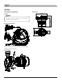
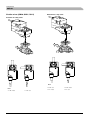
HM270V Circulation pump (GP10) Shuttle valves (QM30, QM31, QN11) Particle filter (HQ1) Safety valve (FL2) Summary Service
Operation control function by the indoor unit
controller FDCW100VNX Compressor 4-way valve Expansion valve Low pressure sensor 81
Operation control function by the outdoor unit
controller 94
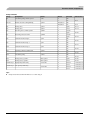
Alarm list Alarm with automatic reset Temperature limiter alarm HM270V alarm FDCW100VNX alarm Hot water alarm Supply alarm 103
103
103
103
104
106
107
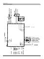
Electrical circuit diagram HM270V FDCW100VNX Temperature sensor Sensor placement Data for sensor in FDCW100VNX Data for sensor in HM270V 108
3 - Thermal cutout 108
4 - OU power failure 109
5 - Low condenser out 110
6 - High condenser out 111
7 - Anti freeze HX 112
8 - High HW temp. 9 High AH temp. 113
10 - High Supply temp. 1, 11 High Supply temp. 2 114
31 - S. fault HP 115
30 - S. fault Outdoor, 32 - S. fault Cond out, 33 - S. fault
Liquid line, 34 - S. fault HW, 35 - S. fault AH, 36 - S. fault
supply 1, 37 - S. fault supply 2 116
E35 - High HX temp 117
E36 - Permanent Hotgas 118
E37 - S. fault Tho-R 119
E38 - S. fault Tho-A 120
E39 - S. fault Tho-D 121
E40 - HP alarm 122
E42 - Current cut 123
E45 - Inverter communication error 124
E48 - Fan alarm 125
E49 - LP alarm 126
E51 - Inverter and fan motor error 128
E53 - S. fault Tho-S 129
E54 - S. fault LPT 130
E57 - Low refrigerant 131
E59 - Inverter error 132
Temperature sensor 133
HM 270V Relay test - forced control DIP switches, FDCW100VNX Circuit board layout Function Component replacement HM270V 148
148
150
152
152
152
153
153
153
153
153
Technical data
Troubleshooting guide Function check, components 138
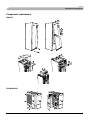
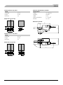
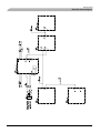
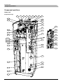
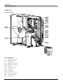
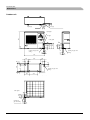
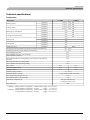
Component positions Indoor unit Outdoor unit Dimensions Indoor unit Outdoor unit Technical specifications Performance Operating temperature range Capacity diagram Accessories Accessories 134
134
136
136
136
137
137
-2-
155
155
160
161
161
161
161
162
162
164
165
165
166
167
167
169
170
171
171
When install the unit, be sure to check whether the selection of installation place, power supply specifications, usage limitation
(piping length, height differences between indoor and outdoor units, power supply voltage and etc.) and installation spaces
SAFETY PRECAUTIONS
z We recommend you to read this “SAFETY PRECAUTIONS” carefully before the installation work in order to gain full
advantage of the functions of the unit and to avoid malfunction due to mishandling.
z
The precautions described below are divided into
and
. The matters with possibilities leading to
serious consequences such as death or serious personal injury due to erroneous handling are listed in the
and
the matters with possibilities leading to personal injury or damage of the unit due to erroneous handling including probability
leading to serious consequences in some cases are listed in
. These are very important precautions for safety.
Be sure to observe all of them without fail.
z
Be sure to confirm no anomaly on the equipment by commissioning after completed installation and explain the operating
methods as well as the maintenance methods of this equipment to the user according to the owner's manual.
z
Keep the installation manual together with owner’s manual at a place where any user can read at any time. Moreover if
necessary, ask to hand them to a new user
WARNING
z Installation must be carried out by the qualified installer.
If you install the system by yourself, it may cause serious trouble such as water leaks, electric shocks, fire and personal injury ,
as a result of a system malfunction.
z Install the system in full accordance with the instruction manual.
Incorrect installation may cause bursts, personal injury, water leaks, electric shocks and fire.
z Use the original accessories and the specified components for installation.
If parts other than those prescribed by us are used, It may cause water leaks, electric shocks, fire and personal injury.
z When installing in small rooms, take prevention measures not to exceed the density limit of refrigerant inthe event of
leakage.
Consult the expert about prevention measures. If the density of refrigerant exceeds the limit in the event of leakage, lack of oxygen can
occur, which can cause serious accidents.
z Ventilate the working area well in the event of refrigerant leakage during installation.
If the refrigerant comes into contact with naked flames, poisonous gas is produced.
z After completed installation, check that no refrigerant leaks from the system.
If refrigerant leaks into the room and comes into contact with an oven or other hot surface, poisonous gas is produced.
z Hang up the unit at the specified points with ropes which can support the weight in lifting for portage. And to avoid jolting
out of alignment, be sure to hang up the unit at 4-point support.
An improper manner of portage such as 3-point support can cause death or serious personal injury due to falling of the unit
z Install the unit in a location with good support.
Unsuitable installation locations can cause the unit to fall and cause material damage and personal injury.
z Ensure the unit is stable when installed, so that it can withstand earthquakes and strong winds.
Unsuitable installation locations can cause the unit to fall and cause material damage and personal injury.
z Ensure that no air enters in the refrigerant circuit when the unit is installed and removed.
If air enters in the refrigerant circuit, the pressure in the refrigerant circuit becomes too high, which can cause burst and personal
injury.
z The electrical installation must be carried out by the qualified electrician in accordance with “the norm for electrical work”
and “national wiring regulation”, and the system must be connected to the dedicated circuit.
Power supply with insufficient capacity and incorrect function done by improper work can cause electric shocks and fire.
z Be sure to shut off the power before starting electrical work.
Failure to shut off the power can cause electric shocks, unit failure or incorrect function of equipment.
z Be sure to use the cables conformed to safety standard and cable ampacity for power distribution work.
Unconformable cables can cause electric leak, anomalous heat production or fire.
z Use the prescribed cables for electrical connection, tighten the cables securely in terminal block and relieve the cables
correctly to prevent overloading the terminal blocks.
Loose connections or cable mountings can cause anomalous heat production or fire.
z Arrange the wiring in the control box so that it cannot be pushed up further into the box. Install the service panel
correctly.
Incorrect installation may result in overheating and fire.
z Do not perform brazing work in the airtight room.
It can cause lack of oxygen.
z Use the prescribed pipes, flare nuts and tools for R410A.
Using existing parts (for R22 or R407C) can cause the unit failure and serious accidents due to burst of the refrigerant circuit.
z Tighten the flare nut by using double spanners and torque wrench according to prescribed method. Be sure not to tighten
the flare nut too much.
Loose flare connection or damage on the flare part by tightening with excess torque can cause burst or refrigerant leaks which
may result in lack of oxygen.
-3-
z Do not open the service valves for liquid line and gas line until completed refrigerant piping work, air tightness test and
evacuation.
If the compressor is operated in state of opening service valves before completed connection of refrigerant piping work, air can
be sucked into refrigerant circuit, which can cause bust or personal injury due to anomalously high pressure in the refrigerant.
z Do not put the drainage pipe directly into drainage channels where poisonous gases such as sulphide gas can occur.
Poisonous gases will flow into the room through drainage pipe and seriously affect the user’s health and safety
z Only use prescribed optional parts. The installation must be carried out by the qualified installer.
If you install the system by yourself, it can cause serious trouble such as water leaks, electric shocks, fire.
z Do not run the unit with removed panels or protections.
Touching rotating equipments, hot surfaces or high voltage parts can cause personal injury due to entrapment, burn or electric
shocks.
z Be sure to fix up the service panels.
Incorrect fixing can cause electric shocks or fire due to intrusion of dust or water.
z Do not perform any repairs or modifications by yourself. Consult the dealer if the unit requires repair.
If you repair or modify the unit, it can cause water leaks, electric shocks or fire.
z Do not perform any change of protective device itself or its setup condition.
The forced operation by short-circuiting protective device of pressure switch and temperature controller or the use of non
specified component can cause fire or burst.
z Be sure to switch off the power supply in the event of installation, inspection or servicing.
If the power supply is not shut off, there is a risk of electric shocks, unit failure or personal injury due to the unexpected start
of fan.
z Consult the dealer or an expert regarding removal of the unit.
Incorrect installation can cause water leaks, electric shocks or fire.
z Stop the compressor before disconnecting refrigerant pipes in case of pump down operation.
If disconnecting refrigerant pipes in state of opening service valves before compressor stopping, air can be sucked, which can
cause burst or personal injury due to anomalously high pressure in the refrigerant circuit.
CAUTION
z Carry out the electrical work for ground lead with care.
Do not connect the ground lead to the gas line, water line, lightning conductor or telephone line’s ground lead. Incorrect
grounding can cause unit faults such as electric shocks due to short-circuiting.
z Use the circuit breaker with sufficient breaking capacity.
If the breaker does not have sufficient breaking capacity, it can cause the unit malfunction and fire.
z Earth leakage breaker must be installed.
If the earth leakage breaker is not installed, it can cause electric shocks.
z Do not use any materials other than a fuse with the correct rating in the location where fuses are to be used.
Connecting the circuit with copper wire or other metal thread can cause unit failure and fire.
z Do not install the unit near the location where leakage of combustible gases can occur.
If leaked gases accumulate around the unit, it can cause fire.
z Do not install the unit where corrosive gas (such as sulfurous acid gas etc.) or combustible gas (such as thinner and
petroleum gases) can accumulate or collect, or where volatile combustible substances are handled.
Corrosive gas can cause corrosion of heat exchanger, breakage of plastic parts and etc. And combustible gas can cause fire.
z Secure a space for installation, inspection and maintenance specified in the manual.
Insufficient space can result in accident such as personal injury due to falling from the installation place.
z When the outdoor unit is installed on a roof or a high place, provide permanent ladders and handrails along the access
route and fences and handrails around the outdoor unit.
If safety facilities are not provided, it can cause personal injury due to falling from the installation place.
z Do not use the indoor unit at the place where water splashes may occur such as in laundries.
Since the indoor unit is not waterproof, it can cause electric shocks and fire.
z Do not install nor use the system close to the equipment that generates electromagnetic fields or high frequency
harmonics.
Equipment such as inverters, standby generators, medical high frequency equipments and telecommunication equipments can
affect the system, and cause malfunctions and breakdowns. The system can also affect medical equipment and
telecommunication equipment, and obstruct its function or cause jamming.
z Do not install the outdoor unit in a location where insects and small animals can inhabit.
Insects and small animals can enter the electric parts and cause damage or fire. Instruct the user to keep the surroundings
z Do not use the base flame for outdoor unit which is corroded or damaged due to long periods of operation.
Using an old and damage base flame can cause the unit falling down and cause personal injury.
z Do not install the unit in the locations listed below.
・Locations where carbon fiber, metal powder or any powder is floating.
・Locations where any substances that can affect the unit such as sulphide gas, chloride gas, acid and alkaline can occur.
・Vehicles and ships.
・Locations where cosmetic or special sprays are often used.
・Locations with direct exposure of oil mist and steam such as kitchen and machine plant.
・Locations where any machines which generate high frequency harmonics are used.
・Locations with salty atmospheres such as coastlines.
-4-
・Locations with heavy snow. (If installed, be sure to provide base flame and snow hood mentioned in the manual)
・Locations where the unit is exposed to chimney smoke.
・Locations at high altitude. (more than 1000m high)
・Locations with ammonic atmospheres.
・Locations where heat radiation from other heat source can affect the unit.
・Locations without good air circulation.
・Locations with any obstacles which can prevent inlet and outlet air of the unit.
・Locations where short circuit of air can occur. (in case of multiple units installation)
・Locations where strong air blows against the air outlet of outdoor unit.
It can cause remarkable decrease in performance, corrosion and damage of components, malfunction and fire.
z Do not install the outdoor unit in the locations listed below.
・Locations where discharged hot air or operating sound of the outdoor unit can bother neighborhood.
・Locations where outlet air of the outdoor unit blows directly to plants.
・Locations where vibration can be amplified and transmitted due to insufficient strength of structure.
・Locations where vibration and operation sound generated by the outdoor unit can affect seriously. (on the wall or at the
place near bed room)
・Locations where an equipment affected by high harmonics is placed. (TV set or radio receiver is placed within 5m)
・Locations where drainage cannot run off safely.
It can affect surrounding environment and cause a claim.
z Do not install the remote controller at the direct sunlight.
It can cause malfunction or deformation of the remote controller.
z Do not use the unit for special purposes such as storing foods, cooling precision instruments and preservation of animals,
plants or art.
It can cause the damage of the items.
z Take care when carrying the unit by hand.
If the unit weights more than 20kg, it must be carried by two or more persons. Do not carry by the plastic straps, always use
the carry handle when carrying the unit by hand. Use gloves to minimize the risk of cuts by the aluminum fins.
z Dispose of any packing materials correctly.
Any remaining packing materials can cause personal injury as it contains nails and wood. And to avoid danger of suffocation, be
sure to keep the plastic wrapper away from children and to dispose after tear it up.
z Pay attention not to damage the drain pan by weld spatter when welding work is done near the indoor unit.
If weld spatter entered into the indoor unit during welding work, it can cause pin-hole in drain pan and result in water leakage.
To prevent such damage, keep the indoor unit in its packing or cover it.
z Be sure to insulate the refrigerant pipes so as not to condense the ambient air moisture on them.
Insufficient insulation can cause condensation, which can lead to moisture damage on the ceiling, floor, furniture and any other
valuables.
z Be sure to perform air tightness test by pressurizing with nitrogen gas after completed refrigerant piping work.
If the density of refrigerant exceeds the limit in the event of refrigerant leakage in the small room, lack of oxygen can occur,
which can cause serious accidents.
z Do not touch any buttons with wet hands.
It can cause electric shocks.
z Do not shut off the power supply immediately after stopping the operation.
Wait at least 5 minutes, otherwise there is a risk of water leakage or breakdown.
z Do not control the system with main power switch.
It can cause fire or water leakage. In addition, the fan can start unexpectedly, which can cause personal injury.
z Do not touch any refrigerant pipes with your hands when the system is in operation.
During operation the refrigerant pipes become extremely hot or extremely cold depending the operating condition, and it can
cause burn injury or frost injury.
Notabilia for units designed for R410A
z Only use R410A refrigerant. R410A is the refrigerant whose pressure is 1.6 times as high as that of conventional refrigerant.
z
The size of charging port of service valve and check joint for R410A are altered from that for conventional refrigerant in order
to prevent the system being charged with the incorrect refrigerant by mistake. And the protruding dimension of pipe for flare
processing and flare nut size for R410A are also altered from that for conventional refrigerant in order to reinforce strength
against the pressure for R410A. Accordingly the dedicated tools for R410A listed in the below mentioned table should be
prepared for installation and servicing.
z
Do not use charging cylinder. Using charging cylinder may alter the composition of refrigerant, which results in making the
performance of the system worse.
z
Refrigerant must be charged always in liquid state from the bottle.
a)
b)
c)
d)
e)
f)
g)
h)
Dedicated tools for R410A
Gauge manifold
Charge hose
Electronic scale for refrigerant charge
Torque wrench
Flare tool
Protrusion control gauge for copper pipe
Vacuum pump adapter
Gas leak detector
-5-
For Home Owners
For Home Owners
-6-
For Home Owners
Information about the installation
Information about the installation
Principle of operation Hydrolution
3
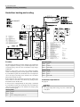
Product information
Hydrolution is a complete modern heat pump system that
offers effective technical energy saving and reduced carbon
dioxide emissions. Heat production is safe and economical
with integrated hot water heater, immersion heater, circulation
pump and climate system in the indoor unit.
1
2
4
Function
The heat is retrieved from the outdoor air through outdoor unit
(FDCW100VNX), where the refrigerant circulated in a closed
piping system transfers the heat from the heat source (outdoor
air) to indoor unit (HM270V).
Hydrolution is a system that can produce heating, hot water
and cooling.
7KHSULQFLSOHGXULQJKHDWLQJFDQEHVLPSOL¿HGDVIROORZV
This eliminates the for holes and coils in the ground.
Features of Hydrolution
7
KHUHIULJHUDQWLQ)'&:91;WDNHVWKHKHDWIURPWKH
outdoor air and is compressed to higher temperature by the
compressor.
Ŷ 2
SWLPDO DQQXDO KHDWLQJ IDFWRU WKDQNV WR WKH LQYHUWHU
controlled compressor.
2. The hot refrigerant (now in gas state) is routed into
HM 270V.
Ŷ 2XWGRRUXQLWZLWKFRPSDFWGLPHQVLRQV
3. The refrigerant releases the heat for further distribution in
the system.
Ŷ 6
SHHGFRQWUROOHGV\VWHPSXPSWKDWVXSSOLHVWKHKHDWSXPS
ZLWKVXLWDEOHV\VWHPÀRZ
Ŷ 2
SWLPL]HGRSHUDWLQJFRVWV7KHVSHHGRIWKHFRPSUHVVRULV
adjusted according to the demand.
Ŷ ,QWHJUDWHGFRLOZDWHUKHDWHULQ+09
Ŷ , QWHJUDWHGFORFNIRUVFKHGXOLQJH[WUDKRWZDWHUDQGWHPSHUDWXUH
lowering/increasing the supply water temperature.
7
KH UHIULJHUDQW QRZ LQ OLTXLG VWDWH LV URXWHG EDFN WR
FDCW100VNX and the process is repeated.
By reversing the entire process, and thereby the refrigerant in
)'&:91;WDNHVWKHKHDWIURPWKHZDWHUDQGUHOHDVHWKH
heat to the outdoor air, the heat pump can cool instead if
necessary.
+09GHWHUPLQHVZKHQ)'&:91;LVWRZRUNDQGQRW
WRZRUNXVLQJWKHFROODWHGGDWDIURPWKHWHPSHUDWXUHVHQVRU,Q
the event of extra heat demands, HM270V can connect
additional heat source in the form of the internal immersion
heater, or any connected external heat source.
Ŷ 3UHSDUHGIRUFRQWURORIWZRKHDWLQJV\VWHPV
Ŷ ,QWHJUDWHGDFWLYHFRROLQJIXQFWLRQ
Ŷ 3RVVLEOHWRFRQQHFWH[WHUQDOKHDWVRXUFHV
-7-
For Home Owners
Front panel, indoor module
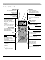
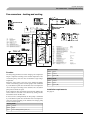
Front panel, indoor unit
Hot water symbol
Addition. heat symbol
If the electrical addition is connected
“I” Electrical step 1
“II” Electrical step 2
“I II” Electrical step 1+2
“III” Electrical step 3
Hot water charging in progress.
“A” Temporary Extra hot water operation in
progress.
“B” Time based Extra hot water operation in
progress, e.g. periodic.
Compressor symbol
Circulation pump symbol
- Compressor is operational
“A” Heating mode
“B” Cooling mode
Operating status
Button pressing (the change does not
need to be confirmed with the enter
button). - Current operating mode
shown in display - Further button press
changes operating mode. Press the
enter button to return to the normal
display mode.
For information about the various operating
modes, see the different sections regarding
comfort settings.
Circulation pump in operation.
With two circulation pumps (requires ESV
22 accessory), the operating pump is also
indicated.
Heating system symbol
A
I II III
AB
I II
Heating in progress.
50.0°C
Hot water temp.
1.0
13.43
Description of current display
parameter
Information symbols
1.0
Extra hot water (XHW)
Extra hot water operation starts with this
button.The operation is cancelled when
the button is pressed again.
The change does not need to be
confirmed with the Enter button.
Menu number
Key lock activated.
Plus button
- Scroll forward in the menu system.
- Increase the value of the selected parameter
Menu 1.0
Pressing the button takes you directly to
menu 1.0.
See the section “Control – General”
Minus button
Offset heating curve
- Turning clockwise (+) offsets the Heating
curve.When the knob is turned
menu 2.0 is shown on the display and
the value for the calculated supply
temperature changes
For details, see Default Heating curve setting.
See the section “Control – General”
Switch
1 Normal mode
All control functions connected.
See the section “Control – General”
- Scroll back in the menu system.
- Reduce the value of the selected parameter
Enter button
- Entering lower layer in the menu system.
- Parameter change activated
- Parameter change confirmed
Status lamp
0 Shutdown
During normal operation, the status lamp
lights green. In the event of an alarm, it
lights red.
Emergency mode
Only the circulation pump and
electric heater (electrical step 2)
are operational.
-8-
For Home Owners
Front panel, indoor module
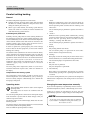
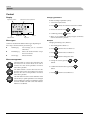
How to use the front panel
All the most common settings are made from the panel such as
FRPIRUWHWFWKDW\RXUHTXLUHWKHKHDWSXPSV\VWHPWRIXO¿O
,QRUGHUWRPDNHIXOOXVHRILWFHUWDLQEDVLFVHWWLQJVPXVWKDYH
been made (see page 11) and the installation in general is
carried out according to the instructions.
Menu 1.0 (the temperature in the water heater) is
normally shown on the display.
The plus and minus buttons and the enter button are
used to scroll through the menu system as well as to
change the set value in some menus.
Menu types (Menu 8.1.1)
Control is classified into different menu types depending on
how “deep” into the controls you need to go.
Ŷ
1RUPDO>1@
KH VHWWLQJV \RX DV D FXVWRPHU
7
often need.
Ŷ
([WHQGHG>8@
KRZV DOO GHWDLOHG PHQXV H[FHSW
6
the service menus.
Ŷ
6HUYLFH>6@
6KRZVDOOPHQXV
Changing of menu type is done from Menu 8.1.1
Quick movement
7RTXLFNO\UHWXUQWRWKHPDLQPHQXIURPDVXEPHQXSUHVV
WKHIROORZLQJEXWWRQ
Key lock
$NH\ORFNFDQEHDFWLYDWHGLQWKHPDLQPHQXVE\VLPXOWDQHRXVO\
pressing the
and the
EXWWRQV7KHNH\V\PEROZLOO
then be shown on the display.
7KHVDPHSURFHGXUHLVXVHGWRGHDFWLYDWHWKHNH\ORFN
Language setting (Menu 8.1.2)
Language used in the display can be chosen in Menu 8.1.2.
-9-
For Home Owners
Comfort setting heating
Comfort setting heating
General
1. “Auto”
The indoor temperature depends on several factors.
HM270V automatically selects the operating mode by
WDNLQJWKHRXWGRRUWHPSHUDWXUHLQWRDFFRXQW7KLVPHDQV
that the operating mode switches between “Heating” and
“Hot water”.
Ŷ 6
XQOLJKW DQG KHDW HPLVVLRQV IURP SHRSOH DQG KRXVHKROG
PDFKLQHVDUHQRUPDOO\VXI¿FLHQWWRNHHSWKHKRXVHZDUP
during the warmer parts of the year.
Ŷ :
KHQLWJHWVFROGHURXWVLGHWKHKHDWLQJV\VWHPPXVWEH
started. The colder it is outside, the warmer radiators and
XQGHUÀRRUKHDWLQJV\VWHPVPXVWEH
The circulation pump is permitted to operate when there is
a need.
2. “AutoC”*
Controlling heat production
HM270V selects operating mode automatically (cooling
can also be selected now) by the outdoor temperature. This
means that the operating mode switches between
“Heating”, “Cooling” and “Hot water”.
Normally, the heat pump heats the water (heating medium) to
the temperature required at a certain outdoor temperature. This
occurs automatically on the basis of the collected temperature
values from the outdoor sensor and sensors on the lines to the
UDGLDWRUV 6XSSO\ ZDWHU VHQVRUV ([WUD DFFHVVRULHV VXFK DV
URRPVHQVRUVFDQLQÀXHQFHWKHWHPSHUDWXUH
,Q RUGHU WR RSHUDWH WKH V\VWHP SURSHUO\ WKH FRUUHFW VHWWLQJV
PXVWEHPDGHRQWKHKHDWSXPS¿UVWVHHWKHVHFWLRQ³'HIDXOW
Heating curve setting”.
The outdoor sensor (mounted on an exterior wall of the house)
senses variations in the outdoor temperature early on, sends the
information to the heat pump control computer and heating
RSHUDWLRQLVVWDUWHG,WGRHVQRWKDYHWREHFROGLQVLGHWKHKRXVH
before the control system is activated. As soon as the
temperature drops outside, the temperature of the water to the
radiators (supply temp.) inside the house is increased
automatically.
The heat pumps flow temperature (Menu 2.0) will hover
DURXQGWKHWKHRUHWLFDOUHTXLUHGYDOXHZKLFKLVLQEUDFNHWVRQ
the display.
The circulation pump is permitted to operate when there is
a need.
3. Heating
Only heating and hot water mode.
The circulation pump is in operation the entire time.
(OHFWLUFKHDWHULVHQHUJL]HGLIQHFHVVDU\
4. Cooling*
Heat pump is used for cooling only if electric heater use is
allowed. Otherwise, it is used for both cooling and hot water.
The circulation pump is in operation the entire time.
5. Hot water
Only hot water is produced.
Only the compressor is operational.
6. Add. Heat only
Heat pump is not operational. The function is activated/
deactivated by pressing in the “operating mode button” for
7 seconds.
Temperature of the heating system
The temperature of the heating system in relation to the
outdoor temperature can be determined by you by selecting a
KHDWFXUYHDQGE\XVLQJWKH³2IIVHWKHDWLQJFXUYH´NQRERQWKH
heat pump’s front panel.
* To use the cooling functions, the system must be designed to
withstand low temperatures and cooling must be activated in
Menu 9.3.3.
Operating status
Changing the room temperature manually
The “Operating mode” button is used to set the required
operating mode.
,I\RXZDQWWRWHPSRUDULO\RUSHUPDQHQWO\LQFUHDVHRUORZHU
The change does not need to be confirmed with the
enter button.
FORFNZLVH WR LQFUHDVH RU DQWLFORFNZLVH WR ORZHU 2QH OLQH
approximately represents 1 degree change in room temperature.
WKHLQGRRUWHPSHUDWXUHWXUQWKH³2IIVHWKHDWLQJFXUYH´NQRE
The current operating mode is shown on the front panel display
when the button is pressed and the mode changes when you
continue to press the button.
The display returns to the normal display mode once the enter
button is pressed.
7KHHOHFWULFKHDWHULVRQO\XVHGIRUDQWLIUHH]HLILWLVGHDFWLYDWHG
in the menu system for all operating modes.
7KHUHDUHGLIIHUHQWRSHUDWLQJPRGHVWRFKRRVH
- 10 -
NOTE
An increase in the room temperature may be inhibited
E\WKHUDGLDWRURUXQGHUÀRRUKHDWLQJWKHUPRVWDWVLIVR
these must be set at 0.
For Home Owners
Comfort setting heating
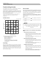
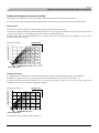
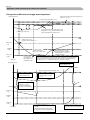
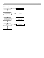
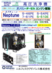
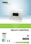
Default Heating curve setting
Setting with diagrams
The basic heating is set using Menu 2.1.2 and with the
³+HDWLQJFXUYHRIIVHW´NQRE
The diagram shows the relation between the outdoor air
temperature in the area and the target supply water temperature
of the heating system. This is set under Menu 2.1.2, “Heating
curve”. Limitations, which are not in the diagrams, can be set
in the control system’s permitted min and max temperatures.
6HH0HQXDQGDVZHOODVDQG
,IWKHURRPWHPSHUDWXUHGRHVQRWUHDFKWKHWDUJHWUHDGMXVWPHQW
may be necessary.
,I\RXGRQRWNQRZWKHFRUUHFWVHWWLQJVXVHWKHEDVLFGDWDIURP
the automatic heating control system diagram on the right.
Heating curve offset -2
HEATING
CURVE
VÄRMEKURVA
FRAMLEDNINGSTEMPERATUR
9
Menu 2.1.2 Heating curve
Supply water temperature
Heating curve
2.1.2
Offset heating curve
* Heating curve offset for system 2 can be made in Menu 3.1
NOTE
oC
70
15 14 13 12
11
10
9
8
60
7
6
50
5
40
4
3
30
2
+5
:DLWRQHGD\EHWZHHQVHWWLQJVVRDVWRVWDELOLVHWKH
temperatures.
1
10
0
- 10
- 20
- 40 oC
- 30
Outdoor air temperature UTETEMPERATUR
-5
FÖRSKJUTNING
VÄRMEKURVA (-2)
OFFSET HEAT CURVE
Heating curve offset 0
Supply water temperature
FRAMLEDNINGSTEMPERATUR
HEATING
CURVE
VÄRMEKURVA
oC
70
15 14 13 12
11
10
9
8
60
7
6
50
5
4
40
3
2
30
1
+5
10
0
- 10
- 20
- 40 oC
- 30
FÖRSKJUTNING
Outdoor air temperature UTETEMPERATUR
VÄRMEKURVA (0)
OFFSET HEAT CURVE
-5
Heating curve offset +2
Supply water temperature
FRAMLEDNINGSTEMPERATUR
HEATING
CURVE
VÄRMEKURVA
oC
70
15 14 13 12 11
10
9
8
7
60
6
5
50
4
3
40
2
30
1
+5
10
0
- 10
- 20
- 30
- 40 oC
FÖRSKJUTNING
Outdoor air temperature UTETEMPERATUR
VÄRMEKURVA (+2)
OFFSET HEAT CURVE
-5
- 11 -
For Home Owners
Comfort setting heating
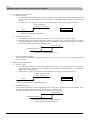
Readjusting the default settings
Comfort setting with room sensor
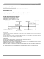
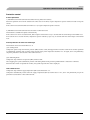
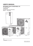
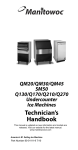
,IWKHUHTXLUHGURRPWHPSHUDWXUHLVQRWREWDLQHGUHDGMXVWPHQW
may be necessary.
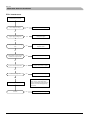
,I0+5*LVLQVWDOOHGRSHUDWLRQPRGHLVFKRVHQQRWRQO\E\
outdoor air temperature but also by room air temperature.
Cold weather conditions
8SSHUOLPLWRIWKHRXWGRRUDLUWHPSHUDWXUHWRRSHUDWHLQ+HDWLQJ
PRGHFDQEHVHWLQ0HQX6WRSWHPS+HDWLQJ
Ŷ :
KHQ WKH URRP WHPSHUDWXUH LV WRR KLJK WKH ³+HDWLQJ
curve” value is decreased in Menu 2.1.2 by one increment.
Warm weather conditions
Ŷ , IWKHURRPWHPSHUDWXUHLVORZLQFUHDVHWKH³+HDWLQJFXUYH
RIIVHW´VHWWLQJE\RQHVWHSFORFNZLVH
Lower limit of the outdoor air temperature to operate in Cooling
PRGHFDQEHVHWLQ0HQX6WDUWWHPS&RROLQJ
Target room air temperature can be adjusted by turning the
NQRERQ0+5*DQGLWLVGLVSOD\HGLQ0HQX
)RUGHWDLOVVHHLQVWUXFWLRQPDQXDOIRU0+5*7KHEHORZ
¿JXUHVKRZVDQH[DPSOHRIPRGHWUDQVLWLRQ
Ŷ , IWKHURRPWHPSHUDWXUHLVKLJKUHGXFHWKH³+HDWLQJFXUYH
RIIVHW´VHWWLQJE\RQHVWHSDQWLFORFNZLVH
Heating system 2
,I WKH KHDWLQJ V\VWHP KDV WZR GLIIHUHQW W\SH RI HPLWWHU OLNH
radiator and under floor heating, it is possible to set two
GLIIHUHQWFDOFXODWHGVXSSO\WHPSHUDWXUH6\VWHPIRUKLJKHU
supply temperature can be set in Menu 2.1.0, and system 2 for
lower supply temperature can be set in Menu 3.0.
Room air temperature
Ŷ :
KHQWKHURRPWHPSHUDWXUHLVWRRORZWKH³+HDWLQJFXUYH´
value is increased in Menu 2.1.2 by one increment.
Cooling
Hot water production
Target
room temp.
(Menu 6.3)
Heating
Stop temp.
Heating (Menu 8.2.3)
Start temp.
Cooling (Menu 8.2.4)
Outdoor air temperature
Vacation set back
Mode transition (in case AutoC is chosen)
LEK
When you are away from home for a long time, it is possible to
set the target supply water temperature for heating lower than
usual to save energy consumption. Also, it is possible to cancel
hot water operation during the period.
)RUGHWDLOVVHH0HQX9DFDWLRQVHWEDFN
Knob
MH-RG10
- 12 -
For Home Owners
Comfort setting cooling
Comfort setting cooling
General
,QWKHGHIDXOWVHWWLQJFRROLQJRSHUDWLRQLVQRWDOORZHG,QRUGHU
to activate, change the setting on the Menu 9.3.3 Cooling
system to “On”.
NOTE
7KHFOLPDWHV\VWHPPXVWPDQDJHFRROLQJRSHUDWLRQ
6HWWLQJVPXVWEHPDGHE\WKHLQVWDOOHUZKHQFRPPLVVLRQLQJ
the system.
,IDURRPVHQVRULVFRQQHFWHGLWVWDUWVDQGVWRSVFRROLQJEDVHG
on both the room and the outdoor temperature. The lowest
calculated supply water temperature is set in Menu 2.2.4.
Cooling operated from the outdoor sensor in
operating mode AutoC
,I WKH FRROLQJ V\VWHP LV VHW WR ³2Q´ LQ 0HQX DQG WKH
outdoor air temperature is greater or equivalent to the set start
temperature for cooling in Menu 8.2.4, cooling starts.
Cooling stops when the outdoor air temperature drops below
the set value minus the set value in Menu 8.2.5.
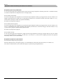
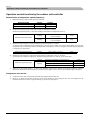
Calculated supply water temperature
The calculated supply water temperature is determined from
the selected cooling curve in Menu 2.2.2 and the offset for
cooling curve, Menu 2.2.1. Limitations, which are not in the
diagram, are included in the control system’s permitted min
temperature.
framledningstemp.
oC
20
15
k=1
10
k=2
5
k=3
0
0
20
30
Outdoor air temperature
40
eUtetem
oC
- 13 -
For Home Owners
Comfort setting hot water
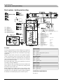
Comfort setting hot water
The integrated water heater is a coil model and is heated by
circulating water, which is heated by the heat pump.
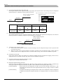
Extra Hot Water
During “normal” consumption it is enough to run the heat
pump to supply the different tapping points of the house with
hot water. The temperature of the hot water in the water heater
then varies between the set values.
,QDOO³([WUDKRWZDWHU´IXQFWLRQVWKHWHPSHUDWXUHRIWKHKRW
ZDWHULQFUHDVHVWHPSRUDULO\7KHWHPSHUDWXUHLV¿UVWLQFUHDVHG
to an adjustable level by the compressor (Menu 1.5) and then
WKH HOHFWULF KHDWHU LV HQHUJL]HG XQWLO WKH ZDWHU WHPSHUDWXUH
reaches the stop temperature (Menu 1.4).
8QGHUVHFWLRQ>1@+RWZDWHUWHPSRQSDJHWKHUHLVD
complete description of menu settings for hot water
temperatures.
7HPSRUDU\³([WUDKRWZDWHU´LVDFWLYDWHGPDQXDOO\ZKLOVWWLPH
based extra hot water is activated using the settings made in the
control computer.
:KHQ
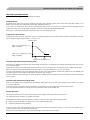
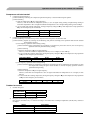
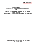
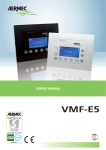
Available volume
Hot water volume
600
8ℓ/min
Ŷ ³ $´DSSHDUVDERYHWKH
is active.
icon, temporary extra hot water
Ŷ ³ %´DSSHDUVDERYHWKH
is active.
icon, time based extra hot water
Supply water volume (ℓ)
500
NOTE
400
³ ([WUDKRWZDWHU´XVXDOO\PHDQVWKDWWKHHOHFWULFKHDWHU
LVDFWLYDWHGUHJDUGOHVVRI$OORZDGGKHDWVHWWLQJPHQX
DQGWKHUHIRUHLQFUHDVHVWKHHOHFWULFDO
consumption.
12ℓ/min
16ℓ/min
300
24ℓ/min
200
“Extra hot water” can be activated in three different
ways:
100
1. Periodic time based extra hot water
0
50
53
56
59
62
Stop temp. HW (°C )
,QWHUYDOEHWZHHQH[WUDKRWZDWHURSHUDWLRQLVVHOHFWHG
in Menu 1.7. Menu 1.8 shows when the next extra hot
water operation is due.
65
*This graph is based on the following conditions :
Inlet water temperature : 15°C
Outlet water temperature : 40°C
Outdoor air temperature : 7°C
Start temp. HW setting :
55°C (Stop temp. HW setting is 58°C or higher)
Stop temp. HW -3°C (Stop temp. HW setting is
lower than 58°C )
The increased temperature is maintained by the
electric heater for one hour.
2. Schedule time based extra hot water
7KHVWDUWDQGVWRSWLPHVIRUWKHGD\RIWKHZHHNZKHQ
the extra hot water operation is required are set in the
sub menus to Menu 7.4.0.
The increased temperature is maintained by the
electric heater for the selected period.
Prioritizing
:KHQ WKH ZDWHU WHPSHUDWXUH LQ WKH WDQN GURSV KHDW SXPS
RSHUDWLRQ VKLIWV WR KRW ZDWHU SURGXFWLRQ ,Q FDVH WKHUH LV
demand for both hot water and heating/cooling for long time,
operation mode is periodically switched between hot water and
heating/cooling. For details, see Menu 1.0 Hot water temp and
0HQX3HULRGVHWWLQJV
3. Temporary extra hot water
- 14 -
([WUDKRWZDWHURSHUDWLRQVWDUWVZKHQ([WUDKRWZDWHU
EXWWRQ LV SUHVVHG DQG LW LV NHSW IRU KRXUV 7KH
operation is cancelled when the button is pressed
again during the period.
The increased temperature is maintained by the
electric heater until the period of time has expired.
For Home Owners
Maintenance
Maintenance
HM270V and FDCW100VNX require minimal maintenance
after commissioning.
Emptying the vessel
Contact your installer if the vessel in HM270V needs emptying.
Hydrolution contains many components and is why monitoring
functions are integrated to help you.
Maintenance of FDCW100VNX
,IVRPHWKLQJDEQRUPDORFFXUVDPHVVDJHDSSHDUVDERXW
malfunctions in the form of different “alarm” texts in display.
FDCW100VNX is equipped with control and monitoring
equipment, however some exterior maintenance is still
necessary.
Checking the safety valves in HM270V
HM270V has been equipped with a safety valve for the water
heater as well as a safety valve for the climate system by the
installer.
The climate system’s safety valve
BP5
FL2
0DNHUHJXODUFKHFNVWKURXJKRXWWKH\HDUWKDWWKHLQOHWJULOOHLV
not clogged by leaves, snow or anything else. During the cold
PRQWKVRIWKH\HDUFKHFNWRPDNHVXUHWKDWWKHUHLVQ¶WDEXLOGXS
RILFHRUIURVWXQGHU)'&:91;6WURQJZLQGFRPELQHG
ZLWKKHDY\VQRZIDOOFDQEORFNWKHLQWDNHDQGH[KDXVWDLUJULOOHV
0DNHVXUHWKDWWKHUHLVQRVQRZRQWKHJULOOHV
$OVRFKHFNWKDWWKHFRQGHQVDWLRQZDWHUGUDLQXQGHU)'&:91;
LVQRWEORFNHG
,I QHFHVVDU\ WKH RXWHU FDVLQJ FDQ EH FOHDQHG XVLQJ D GDPS
cloth. Care must be exercised so that the heat pump is not
scratched when cleaning. Avoid spraying water into the grilles
or the sides so that water penetrates into FDCW100VNX.
3UHYHQW )'&:91; FRPLQJ LQWR FRQWDFW ZLWK DONDOLQH
cleaning agents.
The climate system’s safety valve (FL2) must be completely
VHDOHG&KHFNVPXVWEHFDUULHGRXWUHJXODUO\DVIROORZV
!
Ŷ 2SHQWKHYDOYH
WARNING!
5RWDWLQJIDQ
Ŷ &
KHFNWKDWZDWHUÀRZVWKURXJKWKHYDOYH,IWKLVGRHVQRW
happen, replace the safety valve.
Ŷ &ORVHWKHYDOYHDJDLQ
Ŷ 7
KHKHDWLQJV\VWHPPD\QHHGWREHUHILOOHGDIWHUFKHFNLQJ
the safety valve, see the section “Filling the heating system”.
Hot water heater safety valve
The water heater’s safety valve sometimes releases a little
water after hot water usage. This is because the cold water,
which enters the heater to replace the hot water, expands when
heated causing the pressure to rise and the safety valve to open.
$OVRFKHFNWKHZDWHUKHDWHUVDIHW\YDOYHUHJXODUO\7KH
appearance and location of the safety valve differs between
different installations. Contact your installer for information.
Saving tips
Your Hydrolution produces heat and hot water according to
\RXUQHHGV,WDOVRDWWHPSWVWRFDUU\RXWDOOUHTXLUHPHQWVZLWK
all available “aids” from the control settings made.
The indoor temperature is naturally affected by the energy
FRQVXPSWLRQ7KHUHIRUH WDNH FDUH QRW WR VHW D WHPSHUDWXUH
higher than necessary.
2WKHUNQRZQIDFWRUVWKDWDIIHFWWKHHQHUJ\FRQVXPSWLRQDUH
for example, hot water consumption and the insulation level of
the house, as well as the level of comfort you require.
Also remember:
Ŷ 2
SHQ WKH WKHUPRVWDW YDOYHV FRPSOHWHO\ H[FHSW LQ WKH
URRPVWKDWDUHWREHNHSWFRROHUIRUYDULRXVUHDVRQVHJ
bedrooms).
Pressure gauge in HM270V
7KHZRUNLQJUDQJHRIWKHKHDWLQJV\VWHPLVQRUPDOO\±
EDUZKHQWKHV\VWHPLVFORVHG&KHFNWKLVRQWKHSUHVVXUHJDXJH
%3
Thermostat valves in the radiators and floor loops can
QHJDWLYHO\DIIHFWWKHHQHUJ\FRQVXPSWLRQ7KH\VORZWKHÀRZ
in the heating system, which the heat pump wants to
FRPSHQVDWHZLWKLQFUHDVHGWHPSHUDWXUHV,WWKHQZRUNVKDUGHU
and consumes more electrical energy.
Emptying the hot water heater
The water heater is of the coil type and is drained using the
siphon principle. This can be done either via the drain valve on
the incoming cold water pipe or by inserting a hose into the
cold water connection.
- 15 -
For Home Owners
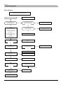
Dealing with comfort disruption
Dealing with comfort disruption
8VHWKHIROORZLQJOLVWWRILQGDQGUHPHG\DQ\KHDWLQJRUKRW
water problems.
Symptom
Low hot water temperature or a lack of hot
water
Low room temperature.
Cause
Circuit or main MCB tripped.
Action
Check and replace blown fuses.
Heat pump and immersion heater do not heat. Check and replace any blown circuit and
main fuses.
Possible earth circuit-breaker tripped.
Reset the earth circuit-breaker, if the earth
circuit-breaker trips repeatedly, call an
electrician.
Switch (SF1) set to mode 0.
Set the switch to 1.
Large hot water demand.
Wait a few hours and check if the hot water
temperature rises.
Too low start temperature setting on the
control system.
Adjust the start temperature setting in menu
1.2.
Possible earth circuit-breaker tripped.
Reset the earth circuit-breaker, if the earth
circuit-breaker trips repeatedly, call an
electrician.
Heat pump and immersion heater do not heat. Check and replace any blown circuit and
main fuses.
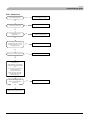
High room temperature.
The compressor does not start.
Incorrect setting of “Heating curve, offset”
and/or “Cooling curve, offset”.
Adjust the settings.
Check Menu2.1.1, 2.1.2 for heating system 1
3.1, 3.2
for heating system 2
2.1.1, 2.2.2 for cooling system
Stop temp heating setting is too low.
Adjust the setting. Check Menu 8.2.3
Circuit or main MCB tripped.
Check and replace blown fuses.
Heat pump in incorrect operating mode “Hot
water” or “Cooling”.
Change operating mode to “Auto” or “ AutoC” .
The current limiter has restricted the current
because many power consumers are being
used in the property.
Switch off one/several of the power consumers.
Incorrect setting of “Heating curve, offset”
and/or “Cooling curve, offset”.
Adjust the settings.
Check Menu2.1.1, 2.1.2 for heating system 1
3.1, 3.2
for heating system 2
2.1.1, 2.2.2 for cooling system
Heat pump in incorrect operating mode.
Change operating mode to “AutoC”.
Start temp cooling setting is too high.
Adjust the setting. Check Menu 8.2.4.
Heat load is too high.
Remove the excess heat load.
Minimum time between compressor starts
alternatively time after power switch on not
being achieved.
Wait 30 minutes and check if the compressor
starts.
Alarm tripped.
See section “Alarms”.
Alarm cannot be reset.
Activate operating mode “Add. heat only”.
Panel gone out.
Check and replace any blown circuit andmain
fuses.
Set switch (SF1) to standby “
- 16 -
”.
For Home Owners
Dealing with comfort disruption
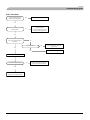
The phenomena mentioned below are not malfunction.
The air conditioning system
sounds as if water is
draining from it.
6RXQGVRIUXVWOLQJRU
gurgling may be heard from
a stopped indoor unit.
The air conditioning system
cannot start operating again
immediately after stopping.
The outdoor unit discharges
water or steam during
heating operation.
The outdoor unit fan is not
running even when the
system is in operation.
6RXQGVRIUXVWOLQJRUJXUJOLQJPD\EHKHDUGZKHQWKHRSHUDWLRQLVVWDUWHGZKHQWKHFRPSUHVVRULV
activated/deactivated during operation, or when the operation is stopped. These are the sounds of the
UHIULJHUDQWÀRZLQJWKURXJKWKHV\VWHP
These sounds can be heard when the air conditioning system is performing automatic control.
2XWGRRUXQLWGRHVQ¶WUHVWDUWGXULQJWKH¿UVWPLQXWHVDIWHUVWRSSLQJRSHUDWLRQ7KLVLVEHFDXVHDFLUFXLW
for protecting the compressor is activated (the fan is operating during this period).
Water or steam is discharge during defrosting operation which removes frost built up on the surface of
the heat exchanger in the outdoor unit in heating mode.
7KHIDQVSHHGLVDXWRPDWLFDOO\FRQWUROOHGDFFRUGLQJWRWKHRXWGRRUDLUWHPSHUDWXUH,WPD\EHVWRSSHGLQ
high outdoor air temperature in case of heating, and in low outdoor air temperature in case of cooling.
Also, the fan is stopped during defrosting operation.
REQUESTS
Hissing sounds are heard
when the operation is
stopped or during defrost
operation.
The fan will suddenly begin to operate even if it is stopped. Do not insert finger and/or stick.
These sounds are generated when the refrigerant valve inside the air conditioning system is activated.
Operating mode “Add. heat only”
,QWKHHYHQWRIPDOIXQFWLRQVWKDWFDXVHDORZLQGRRUWHPSHUDWXUH
you can normally activate “Add. heat only” in HM270V, which
means that heating only occurs with the immersion heater.
Activate the mode by holding in the operating mode button
for 7 seconds.
Note that this is only a temporary solution, as heating with the
LPPHUVLRQKHDWHUGRHVQRWPDNHDQ\VDYLQJV
Emergency mode
(PHUJHQF\PRGHLVDFWLYDWHGE\VHWWLQJWKHVZLWFKWR³
”.
,WLVXVHGZKHQWKHFRQWUROV\VWHPDQGWKHUHE\RSHUDWLQJPRGH
³$GGKHDWRQO\´GRQRWIXQFWLRQDVWKH\VKRXOG(PHUJHQF\
”.
PRGHLVDFWLYDWHGE\VHWWLQJVZLWFK6)WR³
7KHIROORZLQJDSSOLHVLQHPHUJHQF\PRGH
Ŷ 7
KH IURQW SDQHO LV QRW OLW DQG WKH FRQWURO FRPSXWHU LQ
HM270V is not connected.
Ŷ )
'&:91;LVRIIDQGRQO\WKHFLUFXODWLRQSXPSDQG
immersion heater in HM270V are active.
Ŷ $
QHOHFWULFDOVWHSRIN:LVFRQQHFWHG7KHLPPHUVLRQ
heater is controlled by a separate thermostat (BT30).
Ŷ 7
KHDXWRPDWLFKHDWLQJFRQWUROV\VWHPLVQRWRSHUDWLRQDOVR
manual shunt operation is required. Call installer.
- 17 -
For Home Owners
Alarm indications
Alarm indications
There are many monitoring functions integrated in Hydrolution
To alert you to any malfunctions, the control computer transmits
alarm signals that can be read from the front panel display.
Different types of alarms
Ŷ $
ODUPVZLWKDXWRPDWLFUHVHWGRQRWQHHGWREH
DFNQRZOHGJHGZKHQWKHFDXVHKDVGLVDSSHDUHG
Ŷ (
[LVWLQJDODUPVWKDWUHTXLUHFRUUHFWLYHDFWLRQE\\RXRUWKH
installer.
What happens in the event of an alarm?
Ŷ 7
KHEDFNJURXQGOLJKWLQJLQWKHGLVSOD\VWDUWVÀDVKLQJDQG
the status lamp lights red.
Ŷ $FRPSOHWHOLVWRIDODUPVLVRQSDJH
Ŷ 6
RPHDODUPVFKDQJHRSHUDWLQJPRGHWR³$GGKHDWRQO\´
and reduce the supply temperature to the minimum permitted
temperature to notify you that something is wrong.
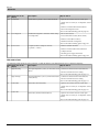
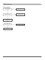
Recommended actions
5
HDGRIIZKLFKDODUPKDVRFFXUUHGIURPWKHKHDWSXPS¶V
display.
$
VDFXVWRPHU\RXFDQUHFWLI\FHUWDLQDODUPV6HHWKHWDEOH
EHORZIRUUHOHYDQWDFWLRQV,IWKHDODUPLVQRWUHFWL¿HGRULV
not included in the table, contact your installer.
Alarm text on the display
Alarm description
Check/remedy before installers/service
technicians are called
LP-ALARM
Tripped low pressure sensor.
Check that the thermostats for the radiators/
under-floor systems are not closed.
HP-ALARM
Tripped high pressure sensor.
Check that the thermostats for the radiators/
under-floor systems are not closed.
OU power failure / OU Com. error
Outdoor unit not powered / Communication
cut
Check that any circuit breakers to the outdoor
unit are not off.
Display not lit
Check and replace any blown circuit and
main fuses.
Check that the circuit breakers to the indoor
unit are off.
Check that the switch (SF1) is in normal position (1).
Resetting alarms
1R KDUP LQ 5HVHWWLQJ DQ DODUP ,I WKH FDXVH RI WKH DODUP
remains, the alarm recurs.
Ŷ :
KHQDQDODUPKDVEHHQWULJJHUHGLWFDQEHUHVHWE\VZLWFKLQJ
+09RIIDQGRQXVLQJWKHVZLWFK6)
Ŷ :
KHQWKHDODUPFDQQRWEHUHVHWXVLQJWKHVZLWFK6)WKH
operating mode, “Add. heat only”, can be activated to
resume a normal temperature level in the house. This is
most easily carried out by holding the “Operating mode”
button in for 7 seconds.
NOTE
5HFXUULQJDODUPVPHDQWKDWWKHUHLVDIDXOWLQWKH
LQVWDOODWLRQ
&RQWDFW\RXULQVWDOOHU
- 18 -
Installation
Installation
- 19 -
Installation
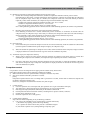
Outdoor unit installation
Outdoor unit installation
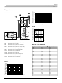
PSB012D955C
◎This installation manual deals with outdoor units and general installation specifications only. For indoor units, refer to the respective
installation manuals supplied with the units.
◎Read this manual carefully before you set to installation work and carry it out according to the instructions contained in this manual.
Check before installation work
[ Accessory ]
Edging
●
●
●
●
1 piece
knock-out hole protection
Model name and power source
Refrigerant piping length
Piping, wiring and miscellaneous small parts
Indoor unit installation manual
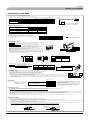
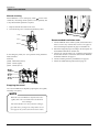
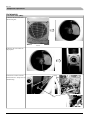
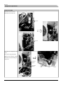
1. HAULAGE AND INSTALLATION
CAUTION
(Take particular care in carrying in or moving the unit, and always perform such an operation with two or more persons.)
When a unit is hoisted with slings for haulage, take into consideration the offset of its gravity center position.
If not properly balanced, the unit can be thrown off-balance and fall.
Pad
1) Delivery
the unit as close as possible to the installation site before removing it
from the packaging.
● When some compelling reason necessitates the unpacking of the unit before it
is carried in, use nylon slings or protective wood pieces so as not to damage
the unit by ropes lifting it.
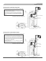
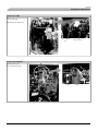
4) Caution about selection of installation location
● Deliver
(1) If the unit is installed in the area where the snow will accumulate, following measures are required.
The bottom plate of unit and intake, outlet may be blocked by snow.
2.Provide a snow hood to
1.Install the unit on the base so that
3.Install the unit under
the bottom is higher than snow cover
eaves or provide the roof
the outdoor unit on site.
surface.
on site.
Regarding outline of a snow
hood, refer to our technical
manual.
Wooden pallet
2) Portage
Heavy
● The
right hand side of the unit as viewed from the front (diffuser side) is heavier.
A person carrying the right hand side must take heed of this fact. A person carrying
the left hand side must hold with his right hand the handle provided on the front
panel of the unit and with his left hand the corner column section.
3) Selection of installation location for the outdoor unit
Be sure to select a suitable installation place in consideration of following conditions.
〇
〇
〇
〇
〇
〇
〇
〇
A place where it is horizontal, stable and can endure the unit weight and will not allow vibration transmittance of the unit.
A place where it can be free from possibility of bothering neighbors due to noise or exhaust air from the unit
A place where the unit is not exposed to oil splashes.
A place where it can be free from danger of flammable gas leakage.
A place where drain water can be disposed without any trouble.
A place where the unit will not be affected by heat radiation from other heat source.
A place where snow will not accumulate.
A place where the unit can be kept away 5m or more from TV set and/or radio receiver in order to avoid any radio
or TV interference.
〇 A place where good air circulation can be secured, and enough service space can be secured for maintenance and
service of the unit safely.
〇 A place where the unit will not be affected by electromagnetic waves and/or high-harmonic waves generated by other
equipment.
〇 A place where chemical substances like sulfuric gas, chloric gas, acid and alkali (including ammonia), which can harm
the unit, will not be generated and not remain.
〇 A place where strong wind will not blow against the outlet air blow of the unit.
Since drain water generated by defrost control may freeze, following measures are required.
execute drain piping work. by using a drain elbow and drain grommets (optional parts). [Refer to
Drain piping work.]
● Recommend setting Defrost Control (SW3-1) and Snow Guard Fan Control (SW3-2). [Refer to Setting SW3-1,
SW3-2.]
● Don't
(2) If the unit can be affected by strong wind, following measures are required.
Strong wind can cause damage of fan (fan motor), or can cause performance degradation, or can trigger
anomalous stop of the unit due to rising of high pressure.
2.Install the outlet air blow side
3.The unit should be installed on
1.Install the outlet air blow side
of the unit in a position
the stable and level foundation.
of the unit to face a wall of
perpendicular to the direction
If the foundation is not level,
building, or provide a fence or
of wind.
tie down the unit with wires.
a windbreak screen.
Wind direction
Wind direction
Over 500 mm
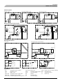
5) Installation space
(mm)
surrounding the unit in the four sides are not acceptable.
● There must be a 1-meter or larger space in the above.
● Where a danger of short-circuiting exists, install guide louvers.
● When more than one unit are installed, provide sufficient intake space consciously so that short-circuiting may not occur.
● Where piling snow can bury the outdoor unit, provide proper snow guards.
● A barrier wall placed in front of the exhaust diffuser must not be higher than the unit.
100V∼140V
● Walls
Example installation
Size
L1
L2
L3
L4
Ⅰ
Open
300
150
5
① Anchor bolt fixed position
● In
installing the unit, fix the unit’s legs with bolts specified on the left.
● The protrusion of an anchor bolt on the front side must be kept within 15 mm.
● Securely install the unit so that it does not fall over during earthquakes or strong winds, etc.
● Refer to the left illustrations for information regarding concrete foundations.
● Install the unit in a level area. (With a gradient of 5 mm or less.)
Improper installation can result in a compressor failure, broken piping within the unit and abnormal noise generation.
Intake
L3
Outlet
service
space
L4
Intake
(
)
L1
Fasten with bolts
(M10-12)
410
Outlet
190
- 20 -
L2
② Notabilia for installation
20
Intake
Ⅲ
500
Open
150
5
580
200
20
6) Installation
Ⅱ
Open
5
300
5
Use a long block to extend the width.
Use a thicker block to anchor deeper.
Installation
Outdoor unit installation
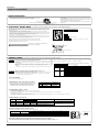
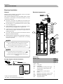
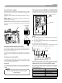
2. REFRIGERANT PIPING WORK
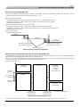
1) Restrictions on unit installation and use
● Check the following points in light of the indoor unit specifications and the installation site.
● Observe the following restrictions on unit installation and use. Improper installation can result in a compressor failure or performance degradation.
Elevation difference between
indoor and outdoor units
When the outdoor unit is positioned higher,
When the outdoor unit is positioned lower,
< Single type >
Marks appearing in the drawing on the right
Single type
Dimensional
restrictions
Restrictions
One-way pipe length of refrigerant piping
12m or less
L
7m or less
H
7m or less
H
Indoor unit
H
L
Outdoor unit
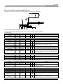
2) Determination of pipe size
● Determine refrigerant pipe size pursuant to the following guidelines based on the indoor unit specifications.
FDCW100VNX
Gas pipe
Outdoor unit connected
φ15.88
Flare
Refrigerant piping
Ǿ15.88
Indoor unit connected
Connected indoor unit model
Ǿ15.88
Liquid pipe
Ǿ9.52
Flare
Ǿ9.52
Ǿ9.52
HM270VS
3) Refrigerant pipe wall thickness and material
●
9.52
Pipe diameter [mm]
Select refrigerant pipes of the table shown on the right wall thickness and material as
specified for each pipe size.
Minimum pipe wall thickness [mm]
Pipe material*
15.88
NOTE
0.8
1.0
O-type pipe
O-type pipe
●
Select pipes having a wall thickness larger
than the specified minimum pipe thickness.
*Phosphorus deoxidized seamless copper pipe C1220T, JIS H3300
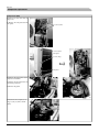
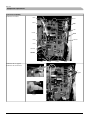
4) On-site piping work
IMPORTANT
● Take
care so that installed pipes may not touch components within a unit. If touching with
an internal component, it will generate abnormal sounds and/or vibrations.
How to remove the service panel
First remove the five screws ( mark) of the service panel and push it down into the
direction of the arrow mark and then remove it by pulling it toward you.
Catch
● The
pipe can be laid in any of the following directions: side right, front, rear and downward.
● Remove a knock-out plate provided on the pipe penetration to open a minimum necessary area and attach an
edging material supplied as an accessory by cutting it to an appropriate length before laying a pipe.
● Carry out the on site piping work with the operation valve fully closed.
● Give sufficient protection to a pipe end (compressed and blazed, or with an adhesive tape) so that water or foreign
matters may not enter the piping.
● Bend a pipe to a radius as large as practical.(R100∼R150) Do not bend a pipe repeatedly to correct its form.
● Flare connection is used between the unit and refrigerant pipe. Flare a pipe after engaging a flare nut onto it.
Flare dimensions for R410A are different from those for conventional R407C. Although we recommend the use
of flaring tools designed specifically for R410A, conventional flaring tools can also be used by adjusting the
measurement of protrusion B with a protrusion control gauge.
●Tighten
Flared pipe end: A (mm)
Copper
0
pipe outer A
ー0.
4
diameter
9.
1
Ǿ6.35
For downward connection
Copper pipe protrusion for flaring: B (mm)
Copper
In the case of a rigid (clutch) type
pipe outer
With an R410A tool
With a conventional tool
diameter
Ǿ6.35
B
A
For rear connection
For side right connection
For front connection
Ǿ9.52
13.
2
Ǿ12.7
16.6
Ǿ12.7
Ǿ15.88
19.7
Ǿ15.88
Ǿ9.52
0∼0.5
0.7∼1.3
a flare joint securely with a double spanner.
CAUTION
Do not apply force beyond proper fastening
torque in tightening the flare nut.
Fix both liquid and gas service valves at the valve
main bodies as illustrated on the right, and then
fasten them, applying appropriate fastening torque.
Operation valve size Tightening torque Tightening angle
(°)
(N-m)
(mm)
Recommended length
of a tool handle (mm)
Ǿ6.35 (1/4")
14∼18
45∼60
150
Ǿ9.52 (3/8")
34∼42
30∼45
200
Ǿ12.7 (1/2")
49∼61
30∼45
250
Ǿ15.88 (5/8")
68∼82
15∼20
300
Do not hold the valve cap area with a spanner.
Use a torque wrench. If a torque wrench is not available,
fasten the flare nut manually first and then tighten it
further, using the left table as a guide.
5) Air tightness test
6) Evacuation
<Work flow>
Gas side
operation valve
Check joint
Outdoor unit
Indoor unit
rize
Close
① Although outdoor and indoor units themselves have been tested for air tightness at the factory, check the connecting pipes after the installation work for air tightness from the operation
valve’s check joint equipped on the outdoor unit side. While conducting a test, keep the operation valve shut all the time.
a) Raise the pressure to 0.5 MPa, and then stop. Leave it for five minutes to see if the pressure drops.
b) Then raise the pressure to 1.5 MPa, and stop. Leave it for five more minutes to see if the pressure drops.
c) Then raise the pressure to the specified level (4.15 MPa), and record the ambient temperature and the pressure.
d) If no pressure drop is observed with an installation pressurized to the specified level and left for about one day, it is acceptable. When the ambient Temperature fall 1℃, the pressure also
fall approximately 0.01 MPa. The pressure, if changed, should be compensated for.
e) If a pressure drop is observed in checking e) and a) – d), a leak exists somewhere. Find a leak by applying bubble test liquid to welded parts and flare joints and repair it. After repair,
conduct an air-tightness test again.
② In conducting an air-tightness test, use nitrogen gas and pressurize the system with nitrogen gas from the gas side. Do not use a medium other than nitrogen gas under any circumstances.
su
res
P
Airtighteness test completed
When the system has remaining moisture
inside or a leaky point, the vacuum gauge
indicator will rise.
Check the system for a leaky point and then
draw air to create a vacuum again.
Vacuuming begins
Pay attention to the following points in addition to the above for the
R410A and compatible machines.
Vacuuming completed
○To prevent a different oil from entering, assign dedicated tools, etc. to each
refrigerant type. Under no circumstances must a gauge manifold and a charge
hose in particular be shared with other refrigerant types (R22, R407C, etc.).
○Use a counterflow prevention adapter to prevent vacuum pump oil from
entering the refrigerant system.
Run the vacuum pump for at least one hour after the vacuum
gauge shows -101kPa or lower. (-755mmHg or lower)
Confirm that the vacuum gauge indicator does not rise even if
the system is left for one hour or more.
Vacuum gauge check
Fill refrigerant
7) Refrigerant charge
(1) Since this unit contains 2.9kg refrigerant including the amount for piping of 12m, it is not necessary to charge addifional refrigerant for piping on site.
● To
charge refrigerant again to the system, recover refrigerant from the system first and then charge the same volume as initial charge.
(2) Charging refrigerant
● Since
R410A refrigerant must be charged in the liquid phase, you should charge it, keeping the container cylinder upside down or using a refrigerant cylinder equipped with a siphon tube.
refrigerant always from the liquid side service port with the operation valve shut. When you find it difficult to charge a required amount, fully open the outdoor unit valves on both liquid and gas sides and charge refrigerant from the
gas (suction) side service port, while running the unit in the cooling mode. In doing so, care must be taken so that refrigerant may be discharged from the cylinder in the liquid phase all the time. When the cylinder valve is throttled down
or a dedicated conversion tool to change liquid-phase refrigerant into mist is used to protect the compressor, however, adjust charge conditions so that refrigerant will gasify upon entering the unit.
● In charging refrigerant, always charge a calculated volume by using a scale to measure the charge volume.
● When refrigerant is charged with the unit being run, complete a charge operation within 30 minutes. Running the unit with an insufficient quantity of refrigerant for a long time can cause a compressor failure.
● Charge
8) Insulation on piping
(1) Dress refrigerant pipes (both gas and liquid pipes) for heat insulation and prevention of dew condensation.
(2) Use a heat insulating material that can withstand 120℃ or a higher temperature. Poor heat insulating capacity can cause heat insulation problems or cable deterioration.
- Improper heat insulation/anti-dew dressing can result in a water leak or dripping causing damage to household effects, etc.
- All gas pipes must be securely heat insulated in order to prevent damage from dripping water that comes from the condensation formed on them during a cooling operation or personal injury from burns because their surface can reach quite a
high temperature due to discharged gas flowing inside during a heating operation.
- Wrap indoor units’ flare joints with heat insulating parts (pipe cover) for heat insulation (both gas and liquid pipes).
- Give heat insulation to both gas and liquid side pipes. Bundle a heat insulating material and a pipe tightly together so that no gaps may be left between them and wrap them together with a connecting cable by a dressing tape.
- Both gas and liquid pipes need to be dressed with 20 mm or thicker heat insulation materials above the ceiling where relative humidity exceeds 70%.
Band
Pipe cover
Wires for connecting indoor
and outdoor units
Liquid piping
Exterior tape
Gas piping
insulation
- 21 -
Installation
Outdoor unit installation
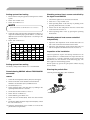
3. DRAIN PIPING WORK
●
Execute drain piping by using a drain elbow and drain grommets supplied separately as
optional parts, where water drained from the outdoor unit is a problem.
○
There are 3 drain holes provided on the bottom plate of an outdoor unit to discharge
condensed water.
When condensed water needs to be led to a drain, etc., install the unit on a flat base
(supplied separately as an optional part) or concrete blocks.
○ Connect a drain elbow as shown in the illustration and close the other two drain holes
with grommets.
○
Drain elbow ( 1 pc.)
Drain grommet
( 2 pcs.)
Hard vinyl chloride pipe for general purpose (VP-16)
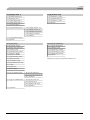
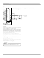
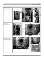
4. ELECTRICAL WIRING WORK For details of electrical cabling, refer to the indoor unit installation manual.
Electrical installation work must be performed by an electrical installation service provider qualified by a power provider of the country.
Electrical installation work must be executed according to the technical standards and other regulations applicable to electrical
installations in the country.
● Ground the unit. Do not connect the grounding wire to a gas pipe, water pipe, lightning rod or telephone grounding wire.
If impropery grounded, an electric shock or malfunction may result.
● A grounding wire must be connected before connecting the power cable. Provide a grounding wire longer than the power cable.
● Do not lay electronic control cables (remote control and signaling wires) and other cables together outside the unit. Laying them
together can result in the malfunctioning or a failure of the unit due to electric noises.
● Fasten cables so that may not touch the piping, etc.
● When cables are connected, make sure that all electrical components within the electrical component box are free of loose
connector coupling or terminal connection and then attach the cover securely. (Improper cover attachment can result in
malfunctioning or a failure of the unit, if water penetrates into the box.)
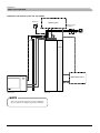
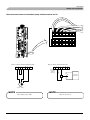
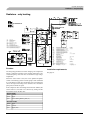
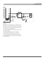
Power source, signal line and ground terminal block
Wiring guide
Wiring diagram
○It is attached on the back side of the service panel.
Outgoing cable direction
● Connect
● In
a pair bearing a common terminal number with an indoor-outdoor connecting wire.
cabling, fasten cables securely so that no external force may work on terminal connections.
terminals are provided in the control box.
○As like the refrigerant pipe, it can be let out in any of the following directions: side right, front,
rear and downward.
● Grounding
Power cable, indoor-outdoor connecting wires
● Always
perform grounding system installation work
with the power cord unplugged.
L
L
N
N
2
1
2
3
3
PE
Outdoor Unit
Indoor Unit
(X2 terminal)
5. COMMISSIONING For details of commissioning, refer to the Indoor unit installation manual
WARNING
●
Before conduct a test run, make sure that the operation valves are open.
Turn on power 6 hours prior to a test run to energize the crank case heater.
Do not turn on the power when the ambient temperature is below −20℃ to avoid breakdown of electronic
component.
● In case of the first operation after turning on power, even if the unit does not operate for 30 minutes, it is
not a breakdown.
● Always give a 3-minute or longer interval before you start the unit again whenever it is stopped.
● Removing the service panel will expose high-voltage live parts and high-temperature parts, which are quite
dangerous.
Take utmost care not to incur an electric shock or burns. Do not leave the unit with the service panel open.
●
A failure to observe these instructions can result in a compressor breakdown.
Items to checkbefore a test run
Item No.used in the
installation manual
● When
you leave the outdoor unit with power supplied to it,
be sure to close the panel.
Item
Check item
Check
Were air-tightness test and vacuum extraction surely performed?
Refrigerant
plumbing
2
Are heat insulation materials installed on both liquid and gas pipes?
Are operation valves surely opened for both liquid and gas systems?
Is the unit free from cabling errors such as uncompleted connection, or reversed phase?
CAUTION
●
●
●
●
When you operate switches (SW3) for on-site setting, be careful not to touch a live part.
You cannot check discharge pressure from the liquid operation valve charge port.
The 4-way valve (20S) is energized during a heating operation.
When power supply is cut off to reset the unit, give 3 minutes or more before you turn on power again
after power is cut off. If this procedure is not observed in turning on power again, “Communication
error between outdoor and indoor unit” may occur.
Doesn’t cabling cross-connect between units, where more than one unit are installed?
Electric
wiring
4
Do indoor-outdoor connecting cables connect between the same terminal numbers?
Is the unit grounded with a dedicated grounding wire not connected to another unit’s grounding wire?
Are cables free from loose screws at their connection points?
Are cables held down with cable clamps so that no external force works onto terminal connections?
1) Test run method
Refer fo the indoor unit installation manual.
2) Checking the state of the unit in operation
Use check joints provided on the piping before and after the four-way valve installed
inside the outdoor unit for checking discharge pressure and suction pressure.
As indicated in the table shown on the right, pressure detected at each point will
vary depending on whether a cooling or heating operation has been selected.
Check joint of the pipe
Charge port of the
gas operation valve
Cooling
operation
Discharge pressure
(High pressure)
Suction pressure
(Low pressure)
Heating
operation
Suction pressure
(Low pressure)
Discharge pressure
(High pressure)
3) Setting SW3-1, SW3-2, on-site
(1) Defrost control switching (SW3-1)
・When this switch is turned ON, the unit will run in the defrost mode more frequently.
・Set this switch to ON, when installed in a region where outdoor temperature falls below zero during the season the unit is run for a heating operation.
(2) Snow guard fan control (SW3-2)
・When this switch is turned on, the outdoor unit fan will run for 10 seconds in every 10 minutes, when outdoor temperature falls to 3℃ or lower and the compressor is not running.
・When the unit is used in a very snowy country, set this switch to ON.
4) Failure diagnosis in a test run
Printed circuit board LED(The cycles of 5 seconds)
Failure event
Action
Indoor Unit Display
Error Code in Error Log
Red LED
Green LED
OU phase error
E34
Blinking once
Blinking continuously
Open phase
HP alarm
E40
Blinking once
Blinking continuously
63H1 actuation or operation with operation valves shut
(occurs mainly during a heating operation)
LP alarm
E49
Blinking once
Blinking continuously
Low pressure error or operation with operation valves shut
(occurs mainly during a cooling operation)
●
Check power cables for loose contact or disconnection
1. Check whether the operation valves are open.
2. If an error has been canceled when 3 minutes have elapsed since a
compressor stop, you can restart the unit by effecting Check Reset
from the remote control unit.
If an error code other than those listed above is indicated, refer to the wiring diagram of the outdoor unit and the indoor unit.
5) The state of the electronic expansion valve.
The following table illustrates the steady states of the electronic expansion valve.
When the unit comes to a normal stop
When the unit comes to an abnormal stop
When power is turned on
Valve for a cooling operation
Valve for a heating operation
Complete shut position
Full open position
During a cooling operation
During a heating operation
During a cooling operation
During a heating operation
Complete shut position
Full open position
Full open position
Full open position
Full open position
Complete shut position
Full open position
Full open position
SWITCHES FOR ON-SITE SETTING
SW3
ON
1
2
3
4
All set to OFF for shipment
6) Heed the following on the first operation after turning on the power supply.
This outdoor unit may start in the standby mode (waiting for a compressor startup), which can continue up to 30 minutes, to prevent the oil level
in the compressor from lowering on the first operation after turning on the circuit breaker. If that is the case, do not suspect a unit failure.
- 22 -
Installation
Indoor unit installation
Indoor unit installation
General information
Assembly
Transport and storage
Ŷ , WLVUHFRPPHQGHGWKDW+09LVLQVWDOOHGLQDURRPZLWK
existing floor drainage, most suitably in a utility room or
boiler room.
HM270V can be transported vertically and must be stored
vertically and in dry conditions.
Ŷ 7
KHVXUIDFHPXVWEHILUPSUHIHUDEO\DFRQFUHWHIORRURU
foundation.
Supplied components
Ŷ , QVWDOO+09ZLWKLWVEDFNWRDQRXWVLGHZDOOLGHDOO\LQ
DURRPZKHUHQRLVHGRHVQRWPDWWHU,IWKLVLVQRWSRVVLEOH
DYRLGSODFLQJLWDJDLQVWDZDOOEHKLQGDEHGURRPRURWKHU
URRPZKHUHQRLVHPD\EHDSUREOHP
LEK
re
or
E ABgiva
er
NIB tur ture sens
perapera
ur fühl
tem
Ute r tememperat018764
doo
Out AussentArtikel
LEK
LEK
Ŷ 7KHXQLWFDQEHDOLJQHGXVLQJWKHDGMXVWDEOHIHHW
Outdoor sensor
Straps for 1 phase connection
Ŷ 5
RXWHSLSHVVRWKH\DUHQRWIL[HGWRDQLQWHUQDOZDOOWKDW
backs on to a bedroom or living room.
LE
K
LE
Ŷ (
QVXUHWKDWWKHUHLVDSSUR[PPIUHHVSDFHLQIURQWRI
and 220 mm above the product for any future service.
K
LE
K
Current sensor, 3 phase
Safety valve with manometer
Dimensioning expansion vessel
The enclosed kit is located behind the front service cover in
HM270V.
Internal volume in HM270V for calculating expansion vessel
LVO7KHH[SDQVLRQYHVVHO¶VYROXPHPXVWEHDWOHDVWRI
the total volume.
Initial pressure and max height difference
The initial pressure of the pressure expansion vessel must be
GLPHQVLRQHGDFFRUGLQJWRWKHPD[LPXPKHLJKW+EHWZHHQ
the vessel and the highest positioned radiator, see figure. An
LQLWLDOSUHVVXUHRIEDUPYSPHDQVDPD[LPXPSHUPLWWHG
KHLJKWGLIIHUHQFHRIP
If the standard initial pressure in the pressure vessel is not high
enough it can be increased by filling via the valve in the
expansion vessel. The expansion vessel’s standard initial
pressure must be entered in the check list on User’s manual.
H
Any change in the initial pressure affects the ability of the
H[SDQVLRQYHVVHOWRKDQGOHWKHH[SDQVLRQRIWKHZDWHU
- 23 -
Installation
Indoor unit installation
Manual shunting
When HM270V is set to emergency mode
on the main
VZLWFK6)WKHKHDWLQJFRQWUROV\VWHPLVQRWLQRSHUDWLRQDQG
LVZK\PDQXDOVKXQWRSHUDWLRQLVUHTXLUHG
1. Depress and lock the button on the valve.
2. Turn the mixing valve to the desired position by hand.
QM1
Knob
Valve
Recommended installation order
&
RQQHFW+09WRWKHFOLPDWHV\VWHPFROGDQGKRWZDWHU
OLQHV DV ZHOO DV DQ\ H[WHUQDO KHDW VRXUFHV 6HH SDJH Also see docking descriptions on page 27 and further on.
Button
2. Install the refrigerant pipes according to the description on
the Installation manual for outdoor unit.
In the emergency mode, the valve position setting should be
PDGHDVIROORZV
3. Connect the current limiter, any centralised load control
DQGH[WHUQDOFRQWDFWVDVZHOODVWKHFDEOHEHWZHHQ+09
DQG)'&:91;6HHSDJH
)URPOHIW
&RQQHFWLQFRPLQJHOHFWULFLW\WR+096HHSDJH
QM30 : Horizontal (Closed)
)ROORZWKHFRPPLVVLRQLQJLQVWUXFWLRQVRQSDJH
QM31 : Vertical (Open)
409HUWLFDO%ĺ$
QM30
QM31
QN11
Emptying the vessel
The vessel in HM270V is emptied by opening the valve (QM1)
DQGVDIHW\YDOYH)/
NOTE
When the vessel in HM270V is emptied via the valve
(QM1), some water will remain in the coil and in the
heat exchanger.
This means that there is a risk of the heat exchanger,
pipes and valves f reezing at low temperatures as well
as a hygienic risk f or the coil in the hot water section.
- 24 -
Installation
Indoor unit installation
Pipe installation
Pump capacity diagram
General
3LSHLQVWDOODWLRQPXVWEHFDUULHGRXWLQDFFRUGDQFHZLWKFXUUHQW
QRUPV DQG GLUHFWLYHV +09 FDQ RSHUDWH ZLWK D UHWXUQ
WHPSHUDWXUHRIXSWR&DQGDQRXWJRLQJWHPSHUDWXUHIURP
WKHXQLWRI&
dp [kPa]
kPa
Available pressure
60
+09LVQRWHTXLSSHGZLWKVKXWRIIYDOYHVWKHVHPXVWEH
installed outside the heat pump to facilitate any future
servicing.
+09FDQEHFRQQHFWHGWRWKHUDGLDWRUV\VWHPÀRRUKHDWLQJ
system and/or fan convectors.
50
40
30
20
10
0
Install the supplied safety valve and manometer.
0
0,05
0,11
0,16
0,22
0,28
0,33
0,39
0,44
0,5
0,55
Flow ℓ/s
Overflow valve
NOTE
Connection of extra circulation pump
:KHQ FRQQHFWLQJ H[WUD FLUFXODWLRQ SXPSV UHTXLUHPHQWV IRU
SUHVVXUH PD[LPXP IORZ HWF PXVW EH PHW 6HH SDJH IRU
location.
A f ree f low is required f or all docking options, which
means that an over f low valve must be installed.
2YHUIORZ YDOYH PXVW EH LQVWDOOHG LQ FDVH H[WUD FLUFXODWLRQ
pump is used.
System requirements
7KLVLVUHTXLUHGIRUPLQLPXPFRQ¿JXUDWLRQ
7KHYROXPHLQWKHFOLPDWHV\VWHPPXVWEHDWOHDVWℓ)RU
V\VWHPVZLWKXQGHUÀRRUKHDWLQJDWOHDVWℓLVUHTXLUHG,I
WKLVLVQRWIXO¿OOHGYROXPHYHVVHOPXVWEHLQVWDOOHG
Connecting the climate system
Pipe connections for the climate system are made at the top.
)RUPRUHRSWLRQVVHHWKHGRFNLQJGHVFULSWLRQRQSDJH
Ŷ $
OOUHTXLUHGVDIHW\GHYLFHVDQGVKXWRIIYDOYHVLQVWDOOHGDV
FORVHWRWKH+09DVSRVVLEOHPXVWEH¿WWHG
Dimensions and pipe connections
Ŷ , QVWDOOWKHEOHHGYDOYHVZKHUHQHFHVVDU\KLJKHVWSRLQWRI
WKHZDWHUV\VWHPLQXVXDOFDVH
40
32 32
55 95 65 52
30
185
(42)
Ŷ 7
KH VDIHW\ YDOYH )/ PXVW EH LQVWDOOHG RQ ;/ DV
LOOXVWUDWHG7KH HQWLUH OHQJWK RI WKH RYHUIORZ ZDWHU SLSH
IURPWKHVDIHW\YDOYHVPXVWEHLQFOLQHGWRSUHYHQWZDWHU
pockets and must also be frost proof.
660
60
BP5
XL2
XL4
XL3
XL1
FL2
XL13
XL15
XL14
Ŷ :
KHQ FRQQHFWLQJ WR D V\VWHP ZLWK WKHUPRVWDWV RQ DOO
UDGLDWRUVDQRYHUÀRZYDOYHPXVWEH¿WWHGRUVRPHRIWKH
WKHUPRVWDWVPXVWEHUHPRYHGWRHQVXUHVXI¿FLHQWÀRZ
Ŷ 6HHVHFWLRQ'RFNLQJVRQSDJHIRURXWOLQHGLDJUDP
XL1 Climate system supply
(22 mm)
XL2 Climate system return
(22 mm)
XL3 Cold water
(22 mm)
XL4 Hot water
(22 mm)
XL13 /LTXLGOLQHUHIULJHUDQW
Ý
XL14 *DVOLQHUHIULJHUDQW
Ý
XL15 Connection safety valve, manometer
--
Installation
Indoor unit installation
Connecting the hot water heater
Connection of external heat source
7KH ZDWHU KHDWHU LQ WKH +09 PXVW EH VXSSOLHG ZLWK
necessary set of valves.
Connect an external heat source such as gas or oil boiler to
;/LQDQG;/RXWRQ+09GLPHQVLRQ*LQWHUQDO
To use these connections, the corresponding “Punchout” parts in
the outer panel must be removed. Also cut off the insulation
above the connections.
Ŷ 7KHUHPXVWEHDPL[LQJYDOYHLIWKHWHPSHUDWXUHH[FHHGV&
Ŷ 7
KHVDIHW\YDOYHPXVWKDYHDPD[LPXPEDURSHQLQJ
SUHVVXUHDQGEHLQVWDOOHGRQWKHLQFRPLQJGRPHVWLFZDWHU
line according to outline diagram. The entire length of the
RYHUÀRZZDWHUSLSHIURPWKHVDIHW\YDOYHVPXVWEHLQFOLQHG
WRSUHYHQWZDWHUSRFNHWVDQGPXVWDOVREHIURVWSURRI
XL8
(Tapered screw, G1)
Ŷ 6HHVHFWLRQ'RFNLQJVRQSDJHIRURXWOLQHGLDJUDP
Extra electric hot water heater
XL9
7KHKHDWSXPSVKRXOGEHVXSSOHPHQWHGZLWKDQHOHFWULFZDWHU
KHDWHULIDKRWWXERURWKHUVLJQL¿FDQWFRQVXPHURIKRWZDWHULV
installed.
VALVE
Ventilkoppel-del
CONNECTION-SPLIT
Waste exchanger part
VvFROMHEATPUMP
från värmepump
HW
Proppas
PLUGGING
CW
Kv
NON-RETURN
Backventil
VALVE
(Tapered screw, G1)
+09KDVDZDVWHDWWKHH[FKDQJHVHFWLRQ$KRVHURXWHV
DQ\ZDVWHZDWHUSDVWWKHSURGXFW¶VHOHFWURQLFVWRPLQLPLVHWKH
risk of damage. If necessary, a hose extension can be connected.
HW
Vv
Blandningsventil-del
MIXINGVALVE-SPLIT
VALVE
CONNECTION-SPLIT
MIXINGVALVE-SPLIT
K
LE
ARMATU
R
Hose to waste
Connecting refrigerant pipes
6HH,QVWDOODWLRQPDQXDOIRURXWGRRUXQLW
--
Installation
Indoor unit installation
Dockings
+\GUROXWLRQFDQEHFRQQHFWHGLQVHYHUDOGLIIHUHQWZD\VVRPH
RIZKLFKDUHVKRZQRQWKHIROORZLQJSDJHV
General
Installation requirements
Max pressure, climate system
0.25 MPa (2.5 Bar)
Max temperature, climate system
+65 °C
Max temperature in HM270V
+65 °C
Max temperature from external heat source
+65 °C
Max supply temperature with compressor at outdoor temp -15°C
+58 °C
Min supply temperature cooling
+7 °C
Max supply temp. cooling
+25 °C
Min volume, climate system during heating, cooling*
Max flow, climate system
50ℓ
100ℓ
0.57ℓ/s
Min flow, climate system
0.15ℓ/s
Nominal**system flow radiators (ЧT=10K)
0.215ℓ/s
Nominal**system flow under floor heating (ЧT=5K)
0.43ℓ/s
Nominal***system flow fan convectors (ЧT=10K)
0.19ℓ/s
Nominal***system flow cooling (ЧT=5K)
0.38ℓ/s
Min volume, climate system during under floor cooling*
5HJDUGVFLUFXODWLQJYROXPH
&N:
&N:
([WHUQDOFLUFXODWLRQSXPSPXVWEHXVHGZKHQWKHSUHVVXUHGURSLQWKHV\VWHPLVJUHDWHUWKDQWKHDYDLODEOHH[WHUQDOSUHVVXUH,QVXFK
FDVHVDE\SDVVOLQHZLWKQRQUHWXUQYDOYHPXVWEHLQVWDOOHG
8VHDQRYHUÀRZYDOYHLIV\VWHPÀRZFDQQRWEHJXDUDQWHHG
Symbol key
Symbol Meaning
Venting valve
Shut-off valve
Non-return valve
Control valve
Safety valve
Temperature sensor
Expansion vessel
P
Pressure gauge
Circulation pump
Shunt / shuttle valve
Fan
- 27 -
Installation
Indoor unit installation
Hydrolution with climate system and any addition
MH-RG10
Climate system
Distributionssystem
Required
safety
Erf. säkerequipment
hetsutr.
FQ1
FL1
BT 1
External
heat source
Tillsats
Outdoor unit
Indoor unit
NOTE
These are the outline diagrams. Actual installations
must be planned according to applicable standards.
- 28 -
Installation
Indoor unit installation
Climate system
Radiator system
Under floor heating systems
GP10
CP1
CP1
CP1
ÖOverflow
verströmn
ings ventil
valve
CM1
volym
CM1
ÖOverflow
verströmvalve
nings ventil
Radiator and under floor heating for heating
as well as fan convector system for cooling
Öve
rströmnivalve
ngs ventil
Overflow
Double under floor heating system for heating
and fan convector for cooling
EP21-GP10
QN12
A
Extrasystem
Extra
system
volume
Extra
Extra system
system
volume
volym
volym
Cooling
Kyla
GP10
GP10
Extrasystem
Extra
system
volume
CM1
Fan convector system
AB
EP21-QN11
EP21-GP10
QN12
EP21
-BT2
A
Cooling
Kyla
B
AB
EP21
-BT2
EP21-QN11
B
EP21-BT3
EP21-BT3
CM1
CP1
CM1
CP1
GP10
Överströmnings
ventil
Overflow
valve
GP10
Överströmnings
ventil
Overflow
valve
External heat source
Solar panels
Wood-fired boiler with accumulator
Solfångare
Solar
panels
V1
Ackumulator
Accumulator
V1
Wood-fired
Vedboiler
panna
Accumulator
Ackumulator
T1
T1
P1
P1
RM
RM
Gas boiler
Oil/pellet boiler
Exhaust air heat pump
ALT.2 2
ALT
On/off
On/Off
On/off
On/Off
ALT.
ALT 11
GP12
Gas V.
GAS
Oil /
Olja/
pellets
pellets
boiler.
RM
F120
F120
GP12
RM
HQ
Explanation
BT1
CM1
CP1
(3í%7
(3í%7
(3í*3
Temperature sensor, outdoor
Expansion vessel
Buffer vessel
Temperature sensor, supply line 2
Temperature sensor, return 2
Circulation pump for heating system 2
(3í41
*3
*3
+4
KF
P1
Shunt valve
External Circulation pump
Circulation pump
Strainer
External control
Circulation pump
- 29 -
41
RM
T1
V1
Shuttle valve for Cooling / Heating
1RQUHWXUQYDOYH
Temperature sensor
Shunt valve
Installation
Indoor unit installation
Electrical installation
General
Electrical components
+09PXVWEHLQVWDOOHGYLDDQLVRODWRUVZLWFKLQDFFRUGDQFH
ZLWKWKHORFDOFRGHVDQGUHJXODWLRQV
5.5 mm
1 mm
2WKHUHOHFWULFDOHTXLSPHQWH[FHSWWKHRXWGRRUVHQVRUVFXUUHQW
WUDQVIRUPHUV DQG RXWGRRU XQLW )'&:91; DUH UHDG\
connected at the factory.
LEK
Ŷ '
LVFRQQHFW WKH LQGRRU XQLW +09 DQG RXWGRRU XQLW
)'&:91;EHIRUHLQVXODWLRQWHVWLQJWKHKRXVHZLULQJ
Ŷ )
RUIXVHUDWLQJVLWLVUHFRPPHQGHGWRXVH$IRUSKDVH
RU$IRUVLQJOHSKDVH
UB1
UB2
(rear)
(front)
Ŷ , I WKH EXLOGLQJ LV HTXLSSHG ZLWK DQ HDUWKIDXOW EUHDNHU
+09VKRXOGEHHTXLSSHGZLWKDVHSDUDWHRQH
SF1
X1
FA2
Ŷ &
RQQHFWLRQPXVWQRWEHFDUULHGRXWZLWKRXWWKHSHUPLVVLRQ
of the electricity supplier and under the supervision of a
TXDOL¿HGHOHFWULFLDQ
2
Ŷ [PP FDEOHPXVWEHXVHGIRUWKHFRQQHFWLRQEHWZHHQ
+09DQG)'&:91;
FA1
BT30
AA22
FD1
X1
Ŷ )
'&:91;LVHTXLSSHGZLWKDVLQJOHSKDVHFRPSUHVVRU
7KLV PHDQV WKDW SKDVH / LV ORDGHG ZLWK $ GXULQJ
compressor operation.
Open
X2
NOTE
Electrical installation and service must be carried out
XQGHUWKHVXSHUYLVLRQRIDTXDOL¿HGHOHFWULFLDQ
Electrical installation and wiring must be carried out
in accordance with the stipulations in force.
NOTE
X3
The switch (SF1) must not be moved from“ 1” or“
”
XQWLOWKHERLOHUKDVEHHQ¿OOHGZLWKZDWHU7KH
circulation pump and immersion heater may become
damaged.
Explanation
Principle diagram, electrical installation
Symbol Type
PEN L1L2L3 distribution
unit
Incoming supply
Isolator switch
Power and
communication cable
AA22
UB1
UB2
X1
X2
Current sensor*
X3
SF1
FA1
FA2
BT30
FD1
* Only in a 3-phase installation.
)RUGHWDLOVVHH&RQQHFWLQJWKHFXUUHQWOLPLWHU
- 30 -
PCB
Cable gland
Cable gland
Terminal block, incoming mains supply
Terminal block, outgoing supply and
communication
Terminal block, external addition
Switch
Miniature circuit breaker, control system
Miniature circuit breaker, outdoor unit
Thermostat, standby mode
Temperature limiter
Scale
length of
conductor
(mm)
ņ
ņ
ņ
14
9
9
ņ
ņ
ņ
ņ
ņ
Installation
Indoor unit installation
Connecting the supply
Connection between HM270V and FDCW100VNX
,QFRPLQJVXSSO\LVFRQQHFWHGRQWHUPLQDOEORFN;YLDFDEOH
gland (UB1). The cable must be dimensioned according to the
applicable norms.
7KH FDEOH EHWZHHQ WKH XQLWV PXVW EH FRQQHFWHG EHWZHHQ
WHUPLQDOEORFNIRULQFRPLQJVXSSO\7%LQ)'&:91;
DQGWHUPLQDOEORFN;LQ+09YLDFDEOHJODQG8%
+09FDQEHFRQQHFWHGZLWKHLWKHU91$&RU9
1AC.
TB
400 V 3NAC: Connect incoming supply according to the
PDUNLQJVRQWHUPLQDO;
230 V 1AC,QVWDOOWKHVXSSOLHGVWUDSVEHWZHHQWHUPLQDOV/
DQG/DVZHOODVEHWZHHQ/DQG/RQLQFRPLQJWHUPLQDO
EORFN;&RQQHFWLQFRPLQJVXSSO\DFFRUGLQJWRWKHWHUPLQDO
markings.
Cable holder
N
L1
L2
L3
PE
400 V 3NAC
N 0 L L1L2L3
Note!
PE
L
N
230 V 1AC
Ŷ )
'&:91;PXVWEHHDUWKHGEHIRUHWKHZLULQJEHWZHHQ
the units is connected.
Ŷ 7
KHZLULQJPXVWEHDWWDFKHGVRWKDWWKHWHUPLQDOEORFNLV
not put under stress.
N 0 L L1L2L3
Ŷ 6FDOHOHQJWKRIFRQGXFWRULVPP
&RQQHFWSKDVHEURZQQHXWUDOEOXHFRPPXQLFDWLRQEODFN
DQGJUH\DVZHOODVHDUWK\HOORZJUHHQDVLOOXVWUDWHG
Miniature circuit-breaker (FA1, FA2)
FDCW100VNX
The automatic heating control system, circulation pumps and
WKHLUZLULQJLQ+09DUHLQWHUQDOO\IXVHSURWHFWHGZLWKD
PLQLDWXUHFLUFXLWEUHDNHU)$
L
N
1
2
3
(AMS
TB 10-12:-X1
2XWGRRU XQLW )'&:91; DQG HTXLSPHQW DUH LQWHUQDOO\
IXVH SURWHFWHG LQ +09 ZLWK D PLQLDWXUH FLUFXLW EUHDNHU
)$
5x2.5 mm2
black
blue
brown
grey
yellow/green
Temperature limiter (FD1)
L
N
2
3
PE
X2
(ACVM
1
7KHWHPSHUDWXUHOLPLWHU)'FXWVWKHFXUUHQWVXSSO\WRWKH
HOHFWULFDODGGLWLRQLIWKHWHPSHUDWXUHULVHVXSEHWZHHQDQG
&DQGFDQEHPDQXDOO\UHVHW
Main circuit breaker size setting (R24 on AA22)
Resetting
(Applicable only in case of 3 phase power supply)
7KHWHPSHUDWXUHOLPLWHU)'LVDFFHVVLEOHEHKLQGWKHIURQW
FRYHU7KHWHPSHUDWXUHOLPLWHULVUHVHWE\¿UPO\SUHVVLQJLQLWV
button.
The size of the property’s main circuit breaker is set using the
NQRE5RQWKHFLUFXLWOLPLWHU3&%$$7KHVHWWLQJFDQ
be read in Menu 8.3.4.
HM270V
Main fuse rating
20
NOTE
Reset the temperature limiter, it may have tripped
during transport.
- 31 -
Knob position
20
IDFWRU\VHWWLQJ
Installation
Indoor unit installation
,IWKHRXWGRRUDLUWHPSHUDWXUHVHQVRUFDEOHUXQVFORVHWRSRZHU
cables, shielded cable must be used.
Setting max power, electric heater (R25 on AA22)
6HWWLQJRIWKHGLIIHUHQWPD[LPXPLPPHUVLRQKHDWHURXWSXWVLV
PDGHXVLQJWKHNQRE5RQWKH3&%$$6HWYDOXH
GLVSOD\HGLQ0HQX7KHIROORZLQJWDEOHRQO\DSSOLHV
ZKHQ0HQX$GGKHDWW\SHLVVHWWR³,QWHUQDOSRZHU´
(factory setting).
If a conduit is used it must be sealed to prevent condensation in
the sensor capsule.
Connecting the current limiter
When the outdoor unit is in operation, maximum heater output
LVOLPLWHGWRN:
Immersion
Knob
Max. electric
Max
loadoutput
When
the outdoor
unitposition
is in operation,
maximum
heater
heater, outpower
phase (A)*
LVOLPLWHGWRN:
put (kW)
(Menu 8.3.2)
4.0
A
2
15
6.0
B
3
15
9.0
C (factory setting) 4
15
When many electrical appliances are connected in the property
at the same time as the electric heater is operating, there is a
ULVNRIWKHSURSHUW\¶VPDLQIXVHWULSSLQJ+09LVHTXLSSHG
ZLWKDQLQWHJUDWHGFXUUHQWOLPLWHUWKDWFRQWUROVWKHHOHFWULFDO
steps and the compressor. If necessary, the electrical steps are
GLVHQJDJHGDQGRUWKHFRPSUHVVRUIUHTXHQF\LVUHGXFHG
A current sensor should be installed on each incoming phase
conductor in to the distribution box to measure the current. The
distribution box is an appropriate installation point.
* Only applies to 3 phase connection.
Connect the current sensor to a multi-core cable in an enclosure
next to the distribution box. Use unscreened multicore cable of
DWOHDVWPP2, from the enclosure to HM270V.
Setting max boiler temperature (R26 on AA22)
The setting of the different maximum boiler temperatures is
PDGHRQWKHNQRE5RQWKH3&%$$6HWYDOXHGLVSOD\HG
in Menu 9.3.1.
In HM270V connect the cable to the PCB (AA22) on terminal
;±
Boiler temperature
Knob position
/FRQQHFWVRQ;DQG;
55
A
60
B
65
C (factory setting)
65
D
65
E
65
F
/FRQQHFWVRQ;DQG;
/FRQQHFWVRQ;DQG;
; LV WKH FRPPRQ WHUPLQDO EORFN IRU WKH WKUHH FXUUHQW
sensors.
L3
L2
L1
PCB, terminal and wiring diagram
7KHIROORZLQJFRQQHFWLRQVDUHPDGHRQWKH3&%$$
AA22-X1
6HHZLULQJGLDJUDPIRUFRPSOHWHZLULQJGLDJUDPRIWKH3&%
1
2
3
4
5
6
7
8
9 10 11 12 13 14 15
16 17
AA22-X1
Connection of centralised demand control/tariff
AA22-X2
AA22-R24
In case centralised demand control or tariff control is used this
FDQ EH FRQQHFWHG WR WKH WHUPLQDO EORFN ; RQ WKH 3&%
(AA22).
AA22-R25
AA22-R26
7DULII$SURKLELWVHQHUJL]LQJLPPHUVLRQKHDWHU,WLVYDOLGZKHQ
;DQG;LVFORVHG
AA22-X4
7DULII%SURKLELWVKHDWSXPSRSHUDWLRQ,WLVYDOLGZKHQ;
DQG;LVFORVHG
Tariff A and B can be used in combination.
Connecting the outdoor air sensor
,QVWDOOWKHRXWGRRUDLUWHPSHUDWXUHVHQVRULQWKHVKDGHRQDZDOO
IDFLQJQRUWKRUQRUWKZHVWVRLWLVXQDIIHFWHGE\WKHPRUQLQJ
VXQ&RQQHFWWKHVHQVRUWRWHUPLQDOEORFN;DQG;RQ
the PCB (AA22) via cable gland UB2. Use a 2 core cable of at least
PP2.
- 32 -
Installation
Indoor unit installation
Connecting external contacts
Docking specific connection
MH-RG 10, sensor for changing the room temperature
HM270V is prepared to control an external circulation pump
*3DQG(3í*3H[WHUQDOPL[LQJYDOYH(3í41
VKXWWOH YDOYH IRU FRROLQJ 41 DV ZHOO DV H[WHUQDO KHDW
source e.g. oil, gas or pellets.
$QH[WHUQDOVHQVRU0+5*FDQEHFRQQHFWHGWR+09
WRFKDQJHWKHÀRZWHPSHUDWXUHDQGWKHWDUJHWURRPWHPSHUDWXUH
&RQQHFWWKHVHQVRUWRWKHWHUPLQDOEORFNIURP;WR;RQ
WKH3&%$$DFFRUGLQJWRZLULQJGLDJUDP
$FWLYDWHGLQ0HQX
7KHWDUJHWVXSSO\ZDWHUWHPSHUDWXUHLVDGMXVWHGDFFRUGLQJWRWKH
JDSEHWZHHQDFWXDOURRPWHPSHUDWXUHDQGVHWURRPWHPSHUDWXUH
7KHVHWURRPWHPSHUDWXUHLVVHWXVLQJWKHNQRERQ0+5*
DQGLVVKRZQLQ0HQX
External circulation pump (GP10, accessory)
&RQQHFWH[WHUQDOFLUFXODWLRQSXPS*3WRWHUPLQDOEORFN
;9;1DQG;3(0D[RXWSXWLV:
7KHFLUFXODWLRQSXPS*3DQG(3í*3LVDFWLYHZKHQ
WKHFLUFXODWLRQSXPS*3LQ+09LVDFWLYH
NOTE
,QDGGLWLRQWKHKHDWLQJV\VWHPWRZKLFKWKHFRQWUROLVYDOLGFDQ
EHFKRVHQLQ0HQX
%HVXUHWRLQVWDOOÀRZUHOLHIYDOYHZKHQDQH[WHUQDO
circulation pump is installed.
Contact for changing the room temperature
An external contact such as a room thermostat or a timer can
EHFRQQHFWHGWR+09WRFKDQJHWKHÀRZWHPSHUDWXUHDQG
FRQVHTXHQWO\ WKH URRP WHPSHUDWXUH 7KH FRQWDFW PXVW EH
potential free and non-locking.
When the contact is closed, the heating curve offset is changed
E\WKHQXPEHURIVWHSVVKRZQKHUH7KHYDOXHLVDGMXVWDEOH
EHWZHHQDQG,WLVSRVVLEOHWRVHWWKHRIIVHWYDOXHRQ
system 1 and 2 independently.
External mixing valve (EP21-QN11, accessory)
Connection and function are described in the Installation
LQVWUXFWLRQVIRUDFFHVVRU\(69
Shuttle valve, cooling (QN12, accessory)
Connection and function are described in the Installation
instructions for accessory VCC 22.
External heat source control
Terminals to be connected
HM270V can control an external heat source.
+HDWLQJV\VWHP;DQG;RQWKH3&%$$
212))FRQWURORIWKHH[WHUQDOKHDWVRXUFHFDQEHGRQHE\
IROORZLQJVHWWLQJV
+HDWLQJV\VWHP;DQG;RQWKH3&%$$
Menu to change the offset value
5HPRYHWKHVWUDSRQWHUPLQDOEORFN;DQG;
+HDWLQJV\VWHP0HQX³([WHUQDODGMXVWPHQW´
&
RQQHFWWKHVLJQDOLQSXWOLQHWRWHUPLQDOEORFN;9
DQG;1PD[$
+HDWLQJV\VWHP0HQX³([WHUQDODGMXVW´
6HW³([WVWHS´LQ0HQX
Contact for activation of “Extra hot water”
An external contact can be connected to HM270V for activation
RIWKH³7HPSRUDU\H[WUDKRWZDWHU´IXQFWLRQ7KHFRQWDFWPXVW
be potential free and non-locking and connected to terminal
EORFN;DQG;RQ3&%$$
When the contact makes for at least one second, the
³7HPSRUDU\ ([WUD KRW ZDWHU´ IXQFWLRQ LV DFWLYDWHG 7KH
function is cancelled automatically after 3 hours.
Alarm outputs
([WHUQDOLQGLFDWLRQRIFRPPRQDODUPVLVSRVVLEOHWKURXJKWKH
UHOD\IXQFWLRQRQWKH3&%$$WHUPLQDOEORFN;±
:KHQVZLWFK6)LVLQWKH³´RU³
in the alarm position.
” position the relay is
- 33 -
Installation
Indoor unit installation
Summary of the function of
External
thermostat
on timer
for
system 1 Tariff A Tariff B L1
the terminals on PCB AA22
Current
sensor
(3phase
only)
L2
External
thermostat
on timer
for
system 2
L3
Outdoor
air
sensor
*
Optional other than
outdoor air sensor (BT1) and
current sensor (L1, L2 and L3)
BT1
X1 : AA22
1 2 3 4 5 6 7 8 9 10 11 12 13 14 15 16 17
X1
X2 : AA22
1
2
3
XR2
XR3
X2
XR2 : Alarm output
XR3 : Operation output
R24 - 26
X6 : AA22
External extra
hot water input
1
2
3
4
X6
X4 : AA22
X4
1 2 3 4 5 6 7 8 9 10 11 12 13 14 15 16
EP21 - BT2
Temp. sensor
supply line
heating system 2
1 6 2
MH-RG10
Room temp.
sensor
- 34 -
EP21 - BT3
Temp. sensor
return line
heating system 2
Installation
Indoor unit installation
How to connect external circulation pump and heat source on X3
1
2
3 4a 4b 5a 5b
X3
How to connect external circulation pump
How to connect external heat source
1 2 3 4a 4b 5a 5b
1 2 3 4a 4b 5a 5b
Jumper wire
on 2 and 3
must be
removed.
XR
L
N
E
GP10
(EP21 - GP10)
NOTE
NOTE
Max output is up to 50W.
Max current is 0.2A
--
External
heat source
Installation
Start-up and inspection
Start-up and inspection
Preparations
Commissioning
&RQQHFW )'&:91; WR +09 UHIULJHUDQW SLSH DQG
ZLULQJDQGFRQQHFW+09WRWKHFOLPDWHV\VWHP
FDCW100VNX
Filling the climate system
&
KHFNWKDWWKHPLQLDWXUHFLUFXLWEUHDNHU)$LQ+09
is on.
(QVXUHWKDWWKHSUHVVXUHJDXJH%3LVYLVLEOH
HM270V
2. Connect a hose to the filling valve (QM1) and open the
YDOYHWR¿OOWKHERLOHUDQGWKHUDGLDWRUV\VWHP
&KHFNWKDWWKHWHPSHUDWXUHOLPLWHU)'KDVQRWWULSSHG
$
IWHUDZKLOHWKHSUHVVXUHJDXJH%3ZLOOVKRZULVLQJ
pressure.
:
KHQWKHSUHVVXUHKDVUHDFKHGDERXWEDUDPL[RIDLU
DQG ZDWHU VWDUWV WR HPHUJH IURP WKH VDIHW\ YDOYH )/
&ORVHWKH¿OOLQJYDOYH40
BP5
6
ZLWFK RQ WKH PDLQ FLUFXLW EUHDNHU DQG FKHFN WKDW WKH
PLQLDWXUHFLUFXLWEUHDNHU)$LQ+09LVRQ
6
HWVZLWFK6)WR³´WKHVZLWFKVKRXGEHVZLWFKHGRQ
IRUKRXUVEHIRUHWKHFRPSUHVVRUFDQEHVWDUWHG
:KHQVZLWFK6)LVVHWWR³´ZDLWDWOHDVWPLQXWH
before setting it back to “1”.
6
HOHFWRSHUDWLQJPRGH³$GGKHDWRQO\´E\KROGLQJLQWKH
operating mode button for 7 seconds.
FL2
6HWWKHGDWHDQGWLPHLQ0HQXDQG
6HWWKHODQJXDJHLQ0HQX
6HOHFW³6HUYLFH´LQ0HQX
6HOHFWDGGLWLRQDOKHDWVRXUFHW\SHLQ0HQX
6
HWWKHIXVHVL]HRQNQRE5&KHFNWKHYDOXHLQ0HQX
8.3.1.
6HWWKHPD[LPPHUVLRQKHDWHURXWSXWRQNQRE5
Check the value in Menu 8.3.2.
QM20
6HOHFWWKHGHVLUHGKHDWLQJFXUYHLQ0HQXDQGVHWWKH
parallel offset using the knob.
&KHFNWKDWWKHKRWZDWHUWHPSHUDWXUHLQ0HQXH[FHHGV
&
QM1
13. When point 12 has been carried out, select operating mode
“Auto”.
The heat pump starts 30 minutes after the outdoor unit is
SRZHUHGLIWKHUHLVDKHDWGHPDQG
Venting the climate system
9HQW+09WKURXJKWKHVDIHW\YDOYH)/YHQWLQJVFUHZV
(QM20), and the rest of the heating system through the relevant
venting valves.
Keep topping up and venting until all air has been removed and
the correct pressure has been obtained.
Filling the hot water coil
7KHKRWZDWHUFRLOLV¿OOHGE\RSHQLQJDKRWZDWHUWDS
--
Installation
Start-up and inspection
Setting system flow heating
Checking external heat source controlled by
(
QVXUHWKDWWKHKHDWSXPSSURGXFHVKHDWLQJIRUWKHFOLPDWH
system.
the signal from HM270V
6HOHFW³2Q´LQ0HQX
6HOHFW³([WVWHS´LQ0HQX
6HOHFW³´LQ0HQX
6
HOHFWRSHUDWLQJPRGH³$GGKHDWRQO\´E\KROGLQJLQWKH
operating mode button for 7 seconds.
NOTE
(
QVXUH WKDW WKH PD[ WHPSHUDWXUH IURP WKH H[WHUQDO KHDW
VRXUFHGRHVQRWH[FHHG&
If it is not shown, set the Menu 8.1.1 to“ Service”.
&
KHFNWKHVXSSO\DQGUHWXUQOLQHWHPSHUDWXUHVLQ0HQX
$GMXVWWKHFLUFXODWLRQSXPSVSHHGLQ0HQXVRWKDWWKH
GLIIHUHQFHEHWZHHQWKHVHWHPSHUDWXUHVLVDFFRUGLQJWRWKH
GLDJUDPEHORZ
6HOHFW³2II ´LQ0HQX
Difference between
supply and return watertemperatur
&KHFNLIWKHVLJQDOZLUHLVFRQQHFWHGDVLQVWUXFWHG
6
HOHFW RSHUDWLQJ PRGH ³$XWR´ E\ SUHVVLQJ WKH RSHUDWLQJ
mode button.
Checking external heat source controlled
independently
$T (°C)
¨
12
$
GMXVWWKHVWDUWWHPSHUDWXUHRIWKHH[WHUQDOKHDWVRXUFHVR
that it starts earlier than the internal electric heater.
10
$
GMXVWWKHVWRSWHPSHUDWXUHRIWKHH[WHUQDOKHDWVRXUFHVR
WKDWWKHWHPSHUDWXUHLQ+09GRHVQRWH[FHHG&
8
6
Inspection of the installation
4
2
0
-15
-10
-5
0
5
10
15
Outdoor air temperature
20
25
(°C)
&XUUHQW UHJXODWLRQV UHTXLUH WKH KHDWLQJ LQVWDOODWLRQ WR EH
inspected before it is commissioned. The inspection must be
FDUULHG RXW E\ D VXLWDEO\ TXDOLILHG SHUVRQ DQG VKRXOG EH
GRFXPHQWHG 8VH WKH FKHFN OLVW RQ WKH IROORZLQJ SDJH7KH
above applies to closed heating systems.
'RQRWUHSODFHDQ\SDUWRIWKHVSOLWV\VWHPZLWKRXWFDUU\LQJ
RXWQHZFKHFNV
Setting system flow cooling
7KHIDFWRU\VHWWLQJLQ0HQXLVUHFRPPHQGHG
Cleaning the particle filter
Commissioning HM270V without FDCW100VNX
connected
&OHDQWKHSDUWLFOH¿OWHU+4DIWHULQVWDOODWLRQ
HM270V
&KHFNWKDWWKHWHPSHUDWXUHOLPLWHU)'KDVQRWWULSSHG
6
ZLWFKRQWKHPDLQFLUFXLWEUHDNHUDQGFKHFNWKDWWKH
PLQLDWXUHFLUFXLWEUHDNHU)$LQ+09LVRQ
6HWVZLWFK6)WR³´
6
HOHFWRSHUDWLQJPRGH³$GGKHDWRQO\´E\KROGLQJLQWKH
operating mode button for 7 seconds.
6HWWKHGDWHDQGWLPHLQ0HQXDQG
6HOHFW³6HUYLFH´LQ0HQX
6HOHFWDGGLWLRQW\SHLQ0HQX
6
HWWKHIXVHVL]HRQNQRE5&KHFNWKHYDOXHLQ0HQX
8.3.1.
6
HWWKHPD[LPPHUVLRQKHDWHURXWSXWRQNQRE5 Check
the value in Menu 8.3.2.
6HOHFWWKHGHVLUHGKHDWLQJFXUYHLQ0HQXDQGVHWWKH
parallel offset using the knob.
- 37 -
Installation
Start-up and inspection
Secondary adjustment
$LULVLQLWLDOO\UHOHDVHGIURPWKHKRWZDWHUDQGYHQWLQJPD\EH
necessary. If gurgling sounds can be heard from HM270V or
IURP WKH FOLPDWH V\VWHP WKH HQWLUH V\VWHP ZLOO UHTXLUH
additional venting.
1RWH8VHEOHHGYDOYH40DQ\H[WHUQDOEOHHGYDOYHVDV
ZHOO DV VDIHW\ YDOYH )/ 7KH ODWWHU PXVW EH RSHUDWHG
FDUHIXOO\DVLWRSHQVTXLFNO\:KHQWKHV\VWHPLVVWDEOHFRUUHFW
pressure and all air eliminated) the automatic heating control
V\VWHPFDQEHVHWDVUHTXLUHG
- 38 -
Installation
Start-up and inspection
Basic menu settings to be checked (Example)
7KLVFKHFNVKHHWVKRZVDQH[DPSOHIRUDUDGLDWRUV\VWHPZLWKDURRPVHQVRU0+5*
CP1
Extra system
volume
Overflow valve
CM1
MH-RG10
FQ1
FL1
BT 1
)LOOLQWKHDOWHUHGVHWYDOXHRQWKHEODQNFHOORI³6HWYDOXH´
$VIRUWKHVHWYDOXHZKLFKLVDOUHDG\ZULWWHQLQWKHFHOOFKHFNLIWKHVHWWLQJLVSURSHUO\FKDQJHG
1. Initial settings
)XQFWLRQ
/DQJXDJH
Date
Time
0HQX1R
8.1.2
7.1
7.2
Default value
(QJOLVK
-
6HWYDOXH
___
___
___
Check
5HPDUNV
/DQJXDJHVHWWLQJXVHGIRUGLVSOD\
Default value
9
6HWYDOXH
___
Check
5HPDUNV
0
___
Min supply heating
Max supply heating
0HQX1R
2.1.2
Knob
(2.1.1)
2.1.4
2.3
&
&
BBB&
BBB&
$GMXVWWKHPLQPD[VXSSO\WHPSHUDWXUHDFFRUGLQJWRWKHUHTXLUHG
feeding temperature of the emitter in the system.
Circ-pump speed heat
BBB
$OORZDGGKHDW
Period time
8.2.1
Heat
PLQ
___
___min
Max time for HW
40min
___min
$GMXVWWKHFLUFXODWLRQSXPSVSHHGVHWWLQJDFFRUGLQJWR³6HWWLQJ
V\VWHPÀRZKHDWLQJ´
6HWWLQJZKHWKHUWKHHOHFWULFKHDWHULVXVHGIRUKHDWLQJ
7KHVHVHWWLQJVGHFLGHWKHRSHUDWLRQSHULRGRIKRWZDWHUDQGKHDWLQJ
ZKHQERWKGHPDQGFRPHVXSDWWKHVDPHWLPH
3HULRGWLPHGH¿QHVDF\FOHWLPHRIKRWZDWHUDQGKHDWLQJRSHUDWLRQ
DQG0D[WLPHIRU+:GH¿QHVWKHPD[LPXPKRWZDWHURSHUDWLRQ
time of the period time.
)XQFWLRQ
5RRPXQLW
5RRPVHQVRUW\SH
0HQX1R
Default value
Off
Off
6HWYDOXH
On
5*
Heating system
Off
6\VWHP
0HQX1R
1.2
1.3
Default value
&
&
2. Heating settings
)XQFWLRQ
Heating curve
Offset heating
Offset value can be set by the knob in the control panel. Value can be
checked in Menu 2.1.1
5RRPVHQVRUVHWWLQJV
Check
5HPDUNV
,QFDVHWKHVHPHQXLVQRWVKRZQRQWKHGLVSOD\VHWWKH0HQXWR
³6´
7KLVVHWWLQJGH¿QHVZKLFKV\VWHPWKHDGMXVWPHQWE\WKHURRPVHQVRU
should be valid.
6HWYDOXH
BBB&
BBB&
Check
5HPDUNV
7KHVHVHWWLQJVVKRXOGEHDGMXVWHGEDVHGRQWKHKRWZDWHUORDGLQWKH
property.
6HWWLQJLVQHFHVVDU\ZKHQXVHUXVHWKLVIXQFWLRQIRUODUJHUKRWZDWHU
demand or for disinfection.
Check
5HPDUNV
+RWZDWHUVHWWLQJV
)XQFWLRQ
6WDUWWHPSHUDWXUH+:
6WRSWHPSHUDWXUH+:
([WUDKRWZDWHUIXQFWLRQ
VHH,WHP
([WUDKRWZDWHUVHWWLQJVLQFDVHLWLVUHTXLUHG
)XQFWLRQ
6WRSWHPSHUDWXUH;+:
+HDWSXPSVWRS;+:
0D[KHDWSWLPH;+:
;+:0RQGD\6XQGD\
(Weekly timer based extra
KRWZDWHUVHWWLQJ
,QWHUYDO;+:
3HULRGLFH[WUDKRWZDWHU
setting)
0HQX1R
1.4
Default value
&
&
30min
6HWYDOXH
BBB&
BBB&
___min
7.4.1 7.4.7
00:00-00:00
___
1.7
0days
___days
Operable temperature range of the outdoor unit can be set.
7RWDORSHUDEOHWLPHRIKHDWSXPSGXULQJ;+:RSHUDWLRQFDQEHVHW
7KHVHWWLQJLVLQYDOLGZKHQVWDUWWLPHDQGVWRSWLPHLVVHWDWWKHVDPH
time (e.g. 22:00 - 22:00)
WKHLQWHUYDORIWKHH[WUDKRWZDWHURSHUDWLRQLVVHW
- 39 -
Control
Start-up and inspection
Checklist: Checks before commissioning
Hot water
Notes
Non-return valve
Is it installed in right direction ?
Safety valve
Is it installed in cold water line ?
Mixer valve
Is it installed in right direction ?
Heating
Notes
System volume
Tank 270ℓ+ System ______ℓ= Total ______ℓ
Safety valve
Is FL2 installed ?
Expansion vessel
Total system volume5% or more ______ℓ
Internal heater
Permitted/prohibited (Menu 8.2.1)
External heat Source
<HVĺ7\SHBBBBBB6HWWLQJ0HQXBBBBBB
No
Yes
No
Heating system 2
Cooling
Checked
Checked
Notes
Checked
Pipe system, condensation insulation
Reversing valve (QN12)
Is it installed in right direction ?
Refrigerant system
Notes
Pipe length (within 12m)
______ m
Height difference (within 7m)
______ m
Test pressurization
41.5 bar
Checked
Leak tracing
End pressure Evacuation
-1 bar or lower for one hour
Electrical installation
Notes
Property’s main fuse
3/1 phase ______ A
Group fuse
3/1 phase ______ A
Current limiter/current sensor
Is it installed properly if the power supply is 3 phase ?
Accessories
Notes
External circulation pump
Yes/No
Buffer vessel
Yes/No Volume ______ℓ
Relief valve
Yes/No
Room sensor
Yes/No Type ______
6HWWLQJ0HQX
Checked
Checked
- 40 -
Control
Control
- 41 -
Control
Control
Control
Display
Changing parameters
Operating symbols
A
I II III
Value of the current parameter
AB
I II
50.0°C
1.0
13.43
Menu name
Menu number
Clock
,QRUGHUWRFKDQJHDSDUDPHWHUYDOXH
$FFHVVWKHUHTXLUHGPHQX
3UHVV
,QFUHDVHRUGHFUHDVHXVLQJ
&RQ¿UPE\SUHVVLQJ
0HQXLVDXWRPDWLFDOO\GLVSOD\HGDJDLQPLQXWHV
DIWHUWKHODVWEXWWRQLVSUHVVHG
Key lock
EXWWRQWKHQXPHULFDOYDOXHVWDUWVWRÀDVK
EXWWRQV
or
EXWWRQ
Menu types
Example
&RQWUROLVFODVVL¿HGLQWRGLIIHUHQWPHQXW\SHVGHSHQGLQJRQ
&KDQJLQJWKHKHDWLQJFXUYH0HQX
KRZ³GHHS´LQWRWKHFRQWUROV\RXQHHGWRJR
7KHVWDUWLQJSRLQWLV0HQX
Ŷ
1RUPDO>1@
7
KH VHWWLQJV \RX DV D FXVWRPHU
RIWHQQHHG
3UHVV
EXWWRQWRPRYHWR0HQX
Ŷ
([WHQGHG>8@
6 KRZV DOO GHWDLOHG PHQXV H[FHSW
WKHVHUYLFHPHQXV
3UHVV
EXWWRQWRPRYHWR0HQX
Ŷ
6HUYLFH>6@
6KRZVDOOPHQXV
3UHVV
EXWWRQWRFKDQJHWKHYDOXH
&KDQJHWKHYDOXHE\SUHVVLQJ
Menu management
7KH3OXVEXWWRQLVXVHGWRPRYHIRUZDUGWRWKH
QH[W PHQX RQ WKH FXUUHQW PHQX OHYHO DQG WR
LQFUHDVH WKH YDOXH RI WKH SDUDPHWHU LQ PHQXV
ZKHUHWKLVLVSRVVLEOH
7KH 0LQXV EXWWRQ LV XVHG WR PRYH EDFN WR WKH
SUHYLRXVPHQXRQWKHFXUUHQWPHQXOHYHODQGWR
GHFUHDVH WKH YDOXH RI WKH SDUDPHWHU LQ PHQXV
ZKHUHWKLVLVSRVVLEOH
or
EXWWRQV
&RQ¿UPWKHVHOHFWHGYDOXHE\SUHVVLQJ
EXWWRQ
7KH(QWHUEXWWRQLVXVHGWRVHOHFWVXEPHQXVRIWKH
FXUUHQWPHQXWRSHUPLWSDUDPHWHUVWREHFKDQJHG
DQGWRFRQ¿UPDQ\FKDQJHVWRSDUDPHWHUV:KHQ
WKHPHQXQXPEHUHQGVZLWKD]HURWKLVLQGLFDWHV
WKDWWKHUHLVDVXEPHQX
- 42 -
3UHVV
EXWWRQWRDFFHVV0HQX
Control
Control
Menu tree
1.0 [N] Hot water temp.
1.1 [N] Max HW/Peroid time
1.2 [N] Start temperature HW
1.3 [N] Stop temperature HW
1.4 [U] Stop temperature XHW
1.5 [U] Heat pump stop XHW
1.6 [U] Max heat p. time XHW
1.7 [U] Interval XHW
1.8 [U] Next XHW action
1.9 [U] HW run time
1.10.0 [S] HW charge act/set
1.10.1 [S] HW charge set temp
1.10.2 [S] Circ-pump speed HW
1.10.3 [S] Circ-pump manual
1.10.4 [S] HW reg min
1.10.5 [S] HW reg P
1.10.6 [S] HW reg Q
1.10.7 [S] HW reg sample time
1.10.8 [S] HW reg xp
1.10.9 [S] HW reg value for xP
1.10.10 [S] Return
1.11.0 [S] CompFreq HW settings
1.11.1 [S] CompFreq HW set
1.11.2 [S] CompFreq manual
1.11.3 [S] CompFreq at +20
1.11.4 [S] CompFreq at -5
1.11.5 [S] Return
1.12 [N] Return
- 43 -
Control
Control
2.0 [N] Supply temp.
2.1.0 [N] Heating settings
2.1.1 [N] Offset heating/Total
2.1.2 [N] Heating curve
2.1.3.0 [U] Own heating curve
2.1.3.1 [U] Supply temp.at +20
2.1.3.2 [U] Supply temp.at -20
2.1.3.3 [U] Buckling temperature
2.1.3.4 [U] Supply t. at buckl.
2.1.3.5 [U] Return
2.1.4 [U] Min supply heating
2.1.5 [U] Circ-pump speed heat
2.1.6 [N] Return
2.2.0 [N] Cooling settings
2.2.1 [N] Offset cooling/Total
2.2.2 [N] Cooling curve
2.2.3.0 [U] Own cooling curve
2.2.3.1 [U] Supply temp.at +20
2.2.3.2 [U] Supply temp.at +40
2.2.3.3 [U] Return
2.2.4 [U] Min supply cooling
2.2.5 [U] Circ-pump speed cool
2.2.6 [N] Return
2.3 [U] Max supply temp.
2.4 [U] External adjustment
2.5 [U] Supply/Return temp.
2.6 [U] Degree minutes
2.7 [N] Return
- 44 -
Control
Control
3.0 [N] Supply temp. 2
4.0 [N] Outdoor temp.
3.1 [N] Offset heating/Tot 2
4.1 [N] Outdoor avg. temp.
3.2 [N] Heating curve 2
4.2 [U] Outdoor filter time
3.3 [U] Min supply temp. 2
4.3 [U] Outdoor avg. 1min.
3.4 [U] Max supply temp. 2
4.4 [N] Return
3.5 [U] External adjust. 2
3.6.0 [U] Own heating curve 2
3.6.1 [U] Supply temp.at +20
3.6.2 [U] Supply temp.at -20
3.6.3 [U] Buckling temperature
3.6.4 [U] Supply t. at buckl
3.6.5 [U] Return
3.7 [U] Supply/Return temp 2
3.8 [N] Return
5.0 [N] Heat pump
6.0 [N] Room temperature*
5.1 [N] Number of starts
6.1 [U] Room compensation
5.2 [N] Run time compressor
6.2 [U] Heating system
5.3 [U] Time to start
6.3 [N] Room temp. setpoint
5.4 [U] Outdoor temp. Tho-A
6.4 [U] Room temp avg. 1min
5.5 [U] Heat Ex Tho-R1
6.5 [U] Room integrator time
5.6 [U] Heat Ex Tho-R2
6.6 [N] Return
5.7 [U] Suction temp. Tho-S
*Requires accessory and activation in Menu 9.3.6.
5.8 [U] Hot gas Tho-D
5.9 [U] Liquid line temp.
5.10 [U] Condensor out / max
5.11 [U] HP
5.12 [U] LP LPT
5.13 [U] Fan speed
5.14.0 [U] CompFreq act/set
5.14.1 [U] OU current CT
5.14.2 [U] Inverter temp Tho-IP
5.14.3 [U] Return
5.15.0 [S] OU communication
5.15.1 [S] Com. error rate
5.15.2 [S] Com. errors
5.15.3 [S] Reset com. errors
5.15.4 [S] Return
5.16 [N] Return
- 45 -
Control
Control
7.0 [N] Clock
8.0 [N] Other adjustments
7.1 [N] Date
8.1.0 [N] Display settings
7.2 [N] Time
8.1.1 [N] Menu type
8.1.2 [N] Language
7.3.0 [U] Temp set back
7.3.1 [U] Set back time
8.1.3 [N] Display contrast
7.3.2 [U] Set back temp +/-
8.1.4 [N] Light intensity
7.3.3 [U] Heating system
8.1.5 [N] Return
7.3.4 [U] Return
8.2.0 [N] Op. mode settings
7.4.0 [U] Extra hot water
8.2.1 [N] Allow add. heat
7.4.1 [U] XHW Monday
8.2.2 [N] Add. heat only
7.4.2 [U] XHW Tuesday
8.2.3 [U] Stop temp. heating
7.4.3 [U] XHW Wednesday
8.2.4 [U] Start temp. cooling
7.4.4 [U] XHW Thursday
8.2.5 [U] Hysteresis
7.4.5 [U] XHW Friday
8.2.6 [N] Return
7.4.6 [U] XHW Saturday
8.3.0 [U] Current limiter
7.4.7 [U] XHW Sunday
8.3.1 [U] Fuse size
8.3.2 [U] Max. electric power
7.4.8 [U] Return
8.3.3 [U] Current phase 1
7.5.0 [U] Vacation set back
7.5.1 [U] Vacation begins
8.3.4 [U] Current phase 2
7.5.2 [U] Vacation ends
8.3.5 [U] Current phase 3
7.5.3 [U] Heating system
8.3.6 [U] Transform. ratio EBV
7.5.4 [U] Offset heating curve
8.3.7 [U] Return
7.5.5 [U] HW off
8.5.0 [U] Period settings
7.5.6 [U] Return
8.5.1 [U] Period time
8.5.2 [U] Max time for HW
7.6 [N] Return
8.5.3 [U] Return
8.6 [N] Return
- 46 -
Control
Control
9.0 [S] Service menus
9.1.0 [S] Heat pump settings
9.1.1 [S] DM start heating
9.1.2 [S] DM start cooling
9.1.3 [S] Stop Temp. heat low
9.1.4 [S] Stop Temp. heat high
9.1.5 [S] Stop Temp. cool low
9.1.6 [S] Stop Temp. cool high
9.1.7 [S] Time bet. starts
9.1.8 [S] Min CompFreq act/set
9.1.9 [S] Max CompFreq act/set
9.1.10 [S] OU current act/max
9.1.11 [S] Tank defrost Temp.
9.1.12 [S] Return
9.2.0 [S] Add. heat settings
9.2.1 [S] DM start add. heat
9.2.2 [S] Time factor
9.2.3 [S] Docking type
9.2.4 [S] Reg. amplification
9.2.5 [S] Reg. integrator time
9.2.6 [S] Shunt amplification
9.2.7 [S] Shunt amplification2
9.2.8 [S] Add. heat type
9.2.9 [S] Return
9.3.0 [S] Operating settings
9.3.1 [S] Max. boiler temp.
9.3.2 [S] Logger
9.3.3 [S] Cooling system
9.3.4 [S] Heating system 2
9.3.5 [S] Room unit
9.3.6 [S] Room sensor type
9.3.7.0 [S] Forced control
9.3.7.1 [S] Forced control
9.3.7.2 [S] K1
9.3.7.3 [S] K2
9.3.7.4 [S] K3
9.3.7.5 [S] K4
9.3.7.6 [S] K5
9.3.7.7 [S] K6
9.3.7.8 [S] K7
9.3.7.9 [S] K8
9.3.7.10 [S] K9
9.3.7.11 [S] K10
9.3.7.12 [S] K11
9.3.7.13 [S] K12
9.3.7.14 [S] K13
9.3.7.15 [S] K14
9.3.7.16 [S] Alarm 1
9.3.7.17 [S] Alarm 2
9.3.7.18 [S] Return
9.3.8 [S] Factory setting
9.3.9 [S] Operating state
- 47 -
Control
Control
9.0 [S] Service menus
9.3.10.0 [S] Floor drying setting
9.3.10.1 [S] Floor drying
9.3.10.2 [S] Period time 1
9.3.10.3 [S] Temp. period 1
9.3.10.4 [S] Period time 2
9.3.10.5 [S] Temp. period 2
9.3.10.6 [S] Return
9.3.11 [S] Supply pump exer.
9.3.12 [S] Supply diff HP
9.3.13 [S] Diff HP add. heat
9.3.14 [S] Block HW/Heating
9.3.15 [S] Heat drop at alarm
9.3.16 [S] Type of HW sensor
9.3.17 [S] Freeze protection HX
9.3.18 [S] Return
9.4 [S] Quick start
9.5.0 [S] System info
9.5.1 [S] Heat pump type
9.5.2 [S] Cpu usage percent
9.5.3 [S] Com rate/1000
9.5.4 [S] Unit w. com. problem
9.5.5 [S] Run time add. heat
9.5.6 [S] Run time hot water
9.5.7 [S] Program version
9.5.8 [S] 106-card version
9.5.9 [S] Display version
9.5.10 [S] Relay card version
9.5.11 [S] Lowest supply temp.
9.5.12 [S] Percent runtime
9.5.13 [S] Period
9.5.14 [S] Run status
9.5.15 [S] Run status last
9.5.16 [S] Run status time
9.5.17 [S] Return
9.6.0 [S] Heat reg. settings
9.6.1 [S] CompFreq
9.6.2 [S] Manual CompFreq
9.6.3 [S] Max deltaF
9.6.4 [S] CompFreq regP
9.6.5 [S] Time min freq start
9.6.6 [S] Time min freq heat
9.6.7 [S] Max diff flow-cFlow
9.6.8 [S] CompFreq GMz
9.6.9 [S] Return
9.7 [S] Reset alarm
9.8.0 [S] Alarm log
9.8.1.0 [S] Log 1
9.8.x.1 [S] Time
9.8.x.2 [S] Alarm type
9.8.x.3 [S] Run status
9.8.x.4 [S] Run status last
9.8.x.5 [S] Run status time
- 48 -
Control
Control
9.0 [S] Service menus
9.8.x.6 [S] Run time compressor
9.8.x.7 [S] Outdoor avg. 1min.
9.8.x.8 [S] Outdoor temp Tho-A
9.8.x.9 [S] Supply/Return temp
9.8.x.10 [S] Condensor out
9.8.x.11 [S] Hot water temp.
9.8.x.12 [S] CompFreq act/set
9.8.x.13 [S] Heat Ex Tho-R1
9.8.x.14 [S] Heat Ex Tho-R2
9.8.x.15 [S] Suction temp. Tho-S
9.8.x.16 [S] Hot gas Tho-D
9.8.x.17 [S] Liquid line temp.
9.8.x.18 [S] HP
9.8.x.19 [S] LP LPT
9.8.x.20 [S] OU current CT
9.8.x.21 [S] Inverter temp Tho-IP
9.8.x.22 [S] Circ-pump speed
9.8.x.23 [S] Relay status 1-8
9.8.x.24 [S] Relay status 9-14
9.8.x.25 [S] Program status 1-8
9.8.x.26 [S] Program status 9-16
9.8.x.27 [S] Return
9.8.2.0 [S] Log 2
9.8.3.0 [S] Log 3
9.8.4.0 [S] Log 4
9.8.5 [S] Clear alarm log
9.8.6 [S] Return
9.9 [S] Return
- 49 -
Control
Control
Main menus
Menu 1.0 [N] Hot water temp.
Menu 9.0 [S] Service menus
7KHFXUUHQWKRWZDWHUWHPSHUDWXUHLQWKHYHVVHOLVVKRZQKHUH
7KLVPHQXDQGLWVVXEPHQXVDUHRQO\VKRZQRQWKHGLVSOD\
VFUHHQZKHQDFFHVVKDVEHHQVHOHFWHGLQ0HQX
)LJXUHRQOHIWVKRZVWKHRQHLQWKHPLGGOHDQGULJKWRQHLQ
EUDFNHWVVKRZVWKHRQHRQWKHERWWRP
Menu 2.0 [N] Supply temp.
7KHFXUUHQWVXSSO\WHPSHUDWXUHIRUWKHKHDWLQJV\VWHPLVVKRZQ
KHUHZLWKWKHFDOFXODWHGVXSSO\WHPSHUDWXUHLQEUDFNHWV
9DOXHVFDQEHUHDGDQGYDULRXVVHWWLQJVFDQEHPDGHIURPWKHVH
VXEPHQXV
NOTE! These settings should only be made by persons
with the necessary expertise.
[N] 1RUPDOFRYHUVWKHQRUPDOXVHU¶VQHHGV
Menu 3.0 [N] Supply temp. 2
7KHFXUUHQWVXSSO\WHPSHUDWXUHIRUKHDWLQJV\VWHPLVVKRZQ
KHUHZLWKWKHFDOFXODWHGVXSSO\WHPSHUDWXUHLQEUDFNHWV
[U] ([WHQGHGVKRZVDOOPHQXVH[FHSWWKHVHUYLFHPHQXV
[S] 6HUYLFHVKRZVDOOPHQXVUHWXUQVWRQRUPDOPLQXWHV
DIWHUWKHODVWEXWWRQZDVSUHVVHG
Menu 4.0 [N] Outdoor temp.
7KHFXUUHQWRXWGRRUDLUWHPSHUDWXUHLVGLVSOD\HGKHUH
Menu 5.0 [N] Heat pump
7KHRXWGRRURSHUDWLRQGDWDDUHVKRZQLQWKHVXEPHQXVWRWKLV
PHQX
7KHIROORZLQJWH[WDSSHDUVLQWKHGLVSOD\
Text
Means
Off
Shown when there is no compressor demand
and none of the following apply.
On
Shown during normal operation with the
compressor.
Initiates
Shown while the compressor is running.
Com. problem Shown in the event of temporary
communication problems.
Defrosting
Shown during defrost.
Oil return
Shown when the compressor is rotated to be
lubricated.
Protection
Shown when the compressor is in some form
of protection or during a start delay of
30 minutes.
Shutdown
Shown in the event of an alarm, tariff B or
Operating mode Addition only.
Stopped
Shown when the outdoor temperature is
outside the compressor’s working range
(too high or too low temperature).
Menu 6.0 [N] Room temperature
7KHURRPWHPSHUDWXUHLVVKRZQKHUHDQGWKHVHWURRPWHPSHUDWXUH
LQEUDFNHWV7KHIDFWRUIRUWKHURRPVHQVRUDQGKHDWLQJV\VWHPWR
FRQWURODUHVHWLQWKHVXEPHQXVWRWKLVPHQX
Menu 7.0 [N] Clock
7KHGDWHDQGWLPHDUHVHWLQWKHVXEPHQXVRIWKLVPHQX'LIIHU
HQWWHPSHUDWXUHUHGXFWLRQVDQGLQFUHDVHVDWVHOHFWHGWLPHVDUH
DOVRVHWIURPWKLVPHQX
Menu 8.0 [N] Other adjustments
7KHPHQXW\SHODQJXDJHRSHUDWLQJPRGHVHWWLQJVDQGORDG
PRQLWRUUHDGLQJDUHVHWLQWKHVXEPHQXVWRWKLVPHQX
--
Control
Control
1.0 [N] Hot water temp.
Menu 1.1 [N] Max HW/Period time
Menu 1.10.0 [S] HW charge act/set
7KHWLPHRIWKHKRWZDWHUSHULRGDQGWKHWLPHIRUWKHZKROH
SHULRG DUH VKRZQ KHUH:KROH SHULRG LV VKRZQ LQ EUDFNHWV
6KRZQIRUERWKKRWZDWHUFKDUJLQJDQGKHDWLQJZKHQQHFHVV
DU\
6KRZVWKHDFWXDODQGWDUJHWYDOXHVIRUWKHKRWZDWHUFKDUJLQJ
WHPSHUDWXUH
7LPHIRU+HDWLQJ0D[ZKHQKHDWLQJLVLQSURJUHVV
+RWZDWHUFKDUJLQJVHWWLQJVDUHPDGHLQWKHVXEPHQXVIRUWKLV
PHQX
Menu 1.10.1 [S] HW charge set temp
7LPHIRU+RWZDWHU0D[LIKRWZDWHUFKDUJLQJLVLQSURJUHVV
Menu 1.2 [N] Start temperature HW
$FWXDOWDUJHWVXSSO\WHPSHUDWXUHGXULQJKRWZDWHURSHUDWLRQ
FDQEHVHW
7KHWHPSHUDWXUHZKHQWKHKHDWSXPSVWDUWVKRWZDWHUFKDUJLQJ
LVVHWKHUH
7DUJHWVXSSO\WHPSHUDWXUHLVVHWDW6WRSWHPSHUDWXUH+:
SOXVWKHVHWYDOXHLQWKLVPHQX
6HWWLQJUDQJH±&
6HWWLQJUDQJH±&
'HIDXOWYDOXH&
'HIDXOWYDOXH&
Menu 1.3 [N] Stop temperature HW
Menu 1.10.2 [S] Circ-pump speed HW
7KHWHPSHUDWXUHZKHQWKHKHDWSXPSVWRSVKRWZDWHUFKDUJLQJ
LVVHWKHUH
7KH VSHHG RI WKH KHDWLQJ PHGLXP SXPS GXULQJ KRW ZDWHU
FKDUJLQJLVVKRZQKHUH
6HWWLQJUDQJH&±&
Menu 1.10.3 [S] Circ-pump manual
'HIDXOWYDOXH&
6HOHFW³2Q´WRPDQXDOO\FRQWUROWKH+:SXPS
Menu 1.4 [U] Stop temperature XHW
6HWWLQJUDQJH2II2Q
7KHGHVLUHGWHPSHUDWXUHGXULQJH[WUDKRWZDWHULVVHWKHUH
'HIDXOWYDOXH2II
6HWWLQJUDQJH&±&
Menu 1.10.4 [S] HW reg min
'HIDXOWYDOXH&
+HUH \RX VHOHFW WKH FRQWURO VLJQDO WKDW WKH KHDWLQJ PHGLXP
SXPSLVWRVWDUWDW
Menu 1.5 [U] Heat pump stop XHW
7KH GHVLUHGVWRSWHPSHUDWXUH GXULQJH[WUD KRWZDWHU IRU WKH
KHDWSXPSLVVHWKHUH
6HWWLQJUDQJH±
6HWWLQJUDQJH±&
Menu 1.10.5 [S] HW reg P
'HIDXOWYDOXH&
'HIDXOWYDOXH
3SDUWIRUWKH+:SXPSUHJXODWRULVVHOHFWHGKHUH
Menu 1.6 [U] Max heat p. time XHW
6HWWLQJUDQJH±
+HUH\RXVHOHFWWKHPD[LPXPDPRXQWRIWLPHWKHKHDWSXPS
FDQFKDUJHKRWZDWHUIRUGXULQJH[WUDKRWZDWHU
'HIDXOWYDOXH
6HWWLQJUDQJH±PLQ
Menu 1.10.6 [S] HW reg Q
4SDUWIRUWKH+:SXPSUHJXODWRULVVHOHFWHGKHUH
'HIDXOWYDOXHPLQ
6HWWLQJUDQJH±
Menu 1.7 [U] Interval XHW
'HIDXOWYDOXH
3HULRGLFWLPHEDVHGH[WUDKRWZDWHULVVHOHFWHGKHUH
([WUDKRWZDWHULVVKXWRIIDWWKHYDOXH³2II ´([WUDKRWZDWHU
LVVWDUWHGZKHQWKHYDOXHLVFRQ¿UPHG
Menu 1.10.7 [S] HW reg sample time
7KHVDPSOHWLPHIRUKRWZDWHUFKDUJLQJLVVHWKHUH
6HWWLQJUDQJH±GD\V
6HWWLQJUDQJH±
'HIDXOWYDOXH2II
'HIDXOWYDOXH
Menu 1.8 [U] Next XHW action
Menu 1.10.8 [S] HW reg xP
7LPHWRWKHQH[WSHULRGLF([WUDKRWZDWHURSHUDWLRQLVOHYHO
VKRZQKHUH
+HUH \RX VHOHFW WKH H[WUD DPSOLILFDWLRQ WKDW WKH +: SXPS
UHJXODWRULVWRXVHEHORZWKHEUHDNLQJSRLQW
6HWWLQJUDQJH±
Menu 1.9 [U] HW run time
6KRZVKRZORQJKRWZDWHUFKDUJLQJZLWKWKHFRPSUHVVRUKDV
EHHQLQSURJUHVVDFFXPXODWHG
'HIDXOWYDOXH
- 51 -
Control
Control
2.0 [N] Supply temp.
Menu 1.10.9 [S] HW reg value for xP
Menu 2.1.0 [N] Heating settings
+HUH\RXVHOHFWWKHEUHDNLQJSRLQWZKHQWKHÀRZLVQRORQJHU
OLQHDUWRWKHFRQWUROVLJQDOLQWKHKHDWLQJPHGLXPSXPS
+HDWLQJVHWWLQJVDUHPDGHLQWKHVXEPHQXVIRUWKLVPHQX
6HWWLQJUDQJH±
Menu 2.1.1 [N] Offset heating/Total
7KHVHOHFWHGKHDWLQJFXUYHRIIVHWLVVKRZQKHUH
'HIDXOWYDOXH
Menu 1.10.10 [S] Return
7KH WRWDO RIIVHW RI WKH KHDW FXUYH LV DOVR VKRZQ KHUH ,W
LQFOXGHVFKHGXOHRXWHUFRPSHQVDWLRQDQGDQ\URRPFRQWURO
5HWXUQWR0HQX
1RWH7KHYDOXHLVFKDQJHGXVLQJWKH³+HDWLQJFXUYHRIIVHW´NQRE
Menu 1.11.0 [S] CompFreq HW settings
6HWWLQJUDQJH±
7KHFRPSUHVVRUIUHTXHQF\GXULQJKRWZDWHUFKDUJLQJLVVKRZQ
KHUH
Menu 2.1.2 [N] Heating curve
6HWWLQJV FDQ EH PDGH UHJDUGLQJ WKH FRPSUHVVRU IUHTXHQF\
GXULQJKRWZDWHUFKDUJLQJLQWKHVXEPHQXVWRWKLVPHQX
7KH VHOHFWHG KHDWLQJ FXUYH LV VKRZQ KHUH$W YDOXH WKH
IXQFWLRQ³2ZQKHDWFXUYH´LVDFWLYDWHGVHH0HQX
6HWWLQJUDQJH±
Menu 1.11.1 [S] CompFreq HW set
'HIDXOWYDOXH
+HUH\RXVHOHFWWKHFRPSUHVVRUIUHTXHQF\IRUKRWZDWHUFKDUJ
LQJGXULQJPDQXDOFRQWURO
Menu 2.1.3.0 [U] Own heating curve
7KLVVHWWLQJLVYDOLGRQO\ZKHQ³2Q´LVVHOHFWHGLQ0HQX
6HWWLQJUDQJH±+]
+HUH \RX FDQ VHOHFW \RXU RZQ FXUYH GHILQLWLRQ7KLV LV DQ
LQGLYLGXDOOLQHDUFXUYHZLWKRQHEUHDNSRLQW<RXVHOHFWDEUHDN
SRLQWDQGWKHDVVRFLDWHGWHPSHUDWXUHV
1RWH7KH³+HDWLQJFXUYH´LQ0HQXPXVWEHVHWWRWR
DFWLYDWHWKLVIXQFWLRQ
'HIDXOWYDOXH+]
Menu 1.11.2 [S] CompFreq manual
6HOHFW³2Q´WRFRQWUROWKHFRPSUHVVRUIUHTXHQF\IRUKRWZDWHU
FKDUJLQJPDQXDOO\
Menu 2.1.3.1 [U] Supply temp.at +20
6HWWLQJUDQJH2II2Q
7KH VXSSO\ WHPSHUDWXUH DW DQ RXWGRRU DLU WHPSHUDWXUH RI
&LVVHOHFWHGKHUH
'HIDXOWYDOXH2II
6HWWLQJUDQJH&±&
'HIDXOWYDOXH&
Menu 1.11.3 [S] CompFreq at +20
7KHFRPSUHVVRUIUHTXHQF\IRUKRWZDWHUFKDUJLQJDWDQRXWGRRU
DLUWHPSHUDWXUHRI&LVVHOHFWHGKHUH
6HWWLQJUDQJH±+]
/LPLWHGE\0HQX0D[VXSSO\WHPS
Menu 2.1.3.2 [U] Supply temp.at -20
7KHVXSSO\WHPSHUDWXUHDWDQRXWGRRUDLUWHPSHUDWXUHRI&
LVVHOHFWHGKHUH
'HIDXOWYDOXH+]
6HWWLQJUDQJH&±&
Menu 1.11.4 [S] CompFreq at -5
7KHFRPSUHVVRUIUHTXHQF\IRUKRWZDWHUFKDUJLQJDWDQRXWGRRU
DLUWHPSHUDWXUHRI&LVVHOHFWHGKHUH
'HIDXOWYDOXH&
/LPLWHGE\0HQX0D[VXSSO\WHPS
6HWWLQJUDQJH±+]
Menu 2.1.3.3 [U] Buckling temperature
'HIDXOWYDOXH+]
+HUH\RXVHOHFWDWZKDWRXWVLGHDLUWHPSHUDWXUHWKHEUHDNSRLQW
VKDOORFFXU
Menu 1.11.5 [S] Return
5HWXUQWR0HQX
Menu 1.12 [N] Return
5HWXUQWR0HQX
6HWWLQJUDQJH±&
'HIDXOWYDOXH&
Menu 2.1.3.4 [U] Supply t. at buckl.
<RXVHWWKHFDOFXODWHGVXSSO\WHPSHUDWXUHIRUWKHEUHDNSRLQWKHUH
6HWWLQJUDQJH&±&
'HIDXOWYDOXH&
/LPLWHGE\0HQX0D[VXSSO\WHPS
Menu 2.1.3.5 [U] Return
5HWXUQWR0HQX
- 52 -
Control
Control
Menu 2.1.4 [U] Min supply heating
Menu 2.2.3.3 [U] Return
7KH VHW PLQLPXP OHYHO IRU WKH VXSSO\ WHPSHUDWXUH WR WKH
KHDWLQJV\VWHPLVVKRZQKHUH
5HWXUQWR0HQX
7KH FDOFXODWHG IORZ WHPSHUDWXUH QHYHU GURSV EHORZ WKH VHW
OHYHOLUUHVSHFWLYHRIWKHRXWGRRUWHPSHUDWXUHKHDWLQJFXUYHRU
LWVRIIVHWKHDWLQJFXUYH
Menu 2.2.4 [N] Min supply cooling
7KH VHW PLQLPXP OHYHO IRU WKH VXSSO\ WHPSHUDWXUH WR WKH
FRROLQJV\VWHPLVVKRZQKHUH
'HIDXOWYDOXH&
7KH FDOFXODWHG IORZ WHPSHUDWXUH QHYHU GURSV EHORZ WKH VHW
OHYHOLUUHVSHFWLYHRIWKHRXWGRRUWHPSHUDWXUHFRROLQJFXUYHRU
LWVRIIVHW
Menu 2.1.5 [U] Circ-pump speed heat
6HWWLQJUDQJH±&
7KH VSHHG RI WKH FLUFXODWLRQ SXPS GXULQJ VSDFH KHDWLQJ LV
VHOHFWHGKHUH
'HIDXOWYDOXH&
6HWWLQJUDQJH±&
6HWWLQJUDQJH±
Menu 2.2.5 [N] Circ-pump speed cool
'HIDXOWYDOXH
7KHVSHHGRIWKHFLUFXODWLRQSXPSGXULQJFRROLQJLVVHOHFWHG
KHUH
Menu 2.1.6 [N] Return
6HWWLQJUDQJH±
5HWXUQWR0HQX
'HIDXOWYDOXH
Menu 2.2.0 [N] Cooling settings
Menu 2.2.6 [N] Return
&RROLQJVHWWLQJVDUHPDGHLQWKHVXEPHQXVIRUWKLVPHQX
5HWXUQWR0HQX
Menu 2.2.1 [N] Offset cooling/Total
Menu 2.3 [U] Max supply temp.
7KHVHOHFWHGFRROLQJFXUYHRIIVHWLVFKDQJHGKHUH
7KH VHW PD[LPXP OHYHO IRU WKH VXSSO\ WHPSHUDWXUH WR WKH
KHDWLQJV\VWHPLVVKRZQKHUH
7KH WRWDO RIIVHW RI WKH FRROLQJ FXUYH LV DOVR VKRZQ KHUH ,W
LQFOXGHVVFKHGXOHRXWHUFRPSHQVDWLRQDQGDQ\URRPFRQWURO
6HWWLQJUDQJH±
'HIDXOWYDOXH
7KHFDOFXODWHGIORZWHPSHUDWXUHQHYHUH[FHHGVWKHVHWOHYHO
LUUHVSHFWLYHRIWKHRXWGRRUWHPSHUDWXUHKHDWLQJFXUYHRURIIVHW
KHDWLQJFXUYH
6HWWLQJUDQJH&±&
Menu 2.2.2 [N] Cooling curve
'HIDXOWYDOXH&
7KH VHOHFWHG FRROLQJ FXUYH LV VKRZQ KHUH$W YDOXH WKH
IXQFWLRQ³2ZQFRROLQJFXUYH´LVDFWLYDWHGVHH0HQX
Menu 2.4 [U] External adjustment
6HWWLQJUDQJH±
'HIDXOWYDOXH
Menu 2.2.3.0 [U] Own cooling curve
+HUH\RXFDQVHOHFW\RXURZQFXUYHGH¿QLWLRQ
1RWH7KH FRROLQJ FXUYH LQ 0HQX PXVW EH VHW WR WR
DFWLYDWHWKLVIXQFWLRQ
&RQQHFWLQJDQH[WHUQDOFRQWDFWIRUH[DPSOHDURRPWKHUPRVWDW
DFFHVVRU\RUDWLPHUDOORZV\RXWRWHPSRUDULO\RUSHULRGLFDOO\
UDLVHRUORZHUWKHURRPWHPSHUDWXUH:KHQWKHH[WHUQDOFRQWDFW
LVFORVHGWKHKHDWLQJFXUYHRIIVHWRUFRROLQJFXUYHRIIVHWLV
FKDQJHGE\WKHQXPEHURIVWHSVVKRZQKHUH
,IURRPFRQWUROLVDFWLYHWKHUHLVDGHJUHHFKDQJHWRWKHVHW
URRPWHPSHUDWXUH
6HWWLQJUDQJH±
Menu 2.2.3.1 [U] Supply temp.at +20
'HIDXOWYDOXH
7KHVXSSO\WHPSHUDWXUHDWDQRXWGRRUDLUWHPSHUDWXUHRI&
LVVHOHFWHGKHUH
Menu 2.5 [U] Supply/Return temp.
6HWWLQJUDQJH&±&
7KH FXUUHQW VXSSO\ DQG UHWXUQ OLQH WHPSHUDWXUHV DUH VKRZQ
KHUH5HWXUQWHPSHUDWXUHLVVKRZQLQEUDFNHWV
'HIDXOWYDOXH&
Menu 2.6 [U] Degree minutes
/LPLWHGE\0HQX0LQVXSSO\FRROLQJ
Menu 2.2.3.2 [U] Supply temp.at +40
7KHVXSSO\WHPSHUDWXUHDWDQRXWGRRUDLUWHPSHUDWXUHRI&
LVVHOHFWHGKHUH
6HWWLQJUDQJH&±&
'HIDXOWYDOXH&
/LPLWHGE\0HQX0LQVXSSO\FRROLQJ
&XUUHQWYDOXHIRUQXPEHURIGHJUHHPLQXWHV,QDGGLWLRQWKLV
YDOXHFDQEHFKDQJHGWRDFFHOHUDWHWKHVWDUWRIKHDWLQJSURGXFWLRQ
RUFRROLQJ
6HWWLQJUDQJH±
'HIDXOWYDOXH
Menu 2.7 [N] Return
5HWXUQWR0HQX
- 53 -
Control
Control
3.0 [N] Supply temp. 2
Menu 3.1 [N] Offset heating/Tot 2
Menu 3.6.1 [U] Supply temp.at +20
7KHKHDWLQJFXUYHRIIVHWLVVHOHFWHGKHUH
7KH VXSSO\ WHPSHUDWXUH DW DQ RXWGRRU DLU WHPSHUDWXUH RI
&LVVHOHFWHGKHUH
7KHWRWDORIIVHWRIKHDWFXUYHLVDOVRVKRZQKHUH,WLQFOXGHV
VFKHGXOHRXWHUFRPSHQVDWLRQDQGDQ\URRPFRQWURO
6HWWLQJUDQJH&±&
6HWWLQJUDQJH±
'HIDXOWYDOXH&
'HIDXOWYDOXH
/LPLWHGE\0HQX0D[VXSSO\WHPS
Menu 3.2 [N] Heating curve 2
Menu 3.6.2 [U] Supply temp.at -20
7KH VHOHFWHG KHDWLQJ FXUYH LV VKRZQ KHUH$W YDOXH WKH
IXQFWLRQ³2ZQKHDWFXUYH´LVDFWLYDWHGVHH0HQX
7KHVXSSO\WHPSHUDWXUHDWDQRXWGRRUDLUWHPSHUDWXUHRI&
LVVHOHFWHGKHUH
6HWWLQJUDQJH±
6HWWLQJUDQJH&±&
'HIDXOWYDOXH
'HIDXOWYDOXH&
Menu 3.3 [U] Min supply temp. 2
/LPLWHGE\0HQX0D[VXSSO\WHPS
7KHVHWPLQLPXPOHYHOIRUWKHVXSSO\WHPSHUDWXUHIRUKHDWLQJ
V\VWHPLVVKRZQKHUH
Menu 3.6.3 [U] Buckling temperature
7KH FDOFXODWHG IORZ WHPSHUDWXUH QHYHU GURSV EHORZ WKH VHW
OHYHOLUUHVSHFWLYHRIWKHRXWGRRUWHPSHUDWXUHKHDWLQJFXUYHRU
LWVRIIVHW
6HWWLQJUDQJH±&
+HUH\RXVHOHFWDWZKDWRXWVLGHDLUWHPSHUDWXUHWKHEUHDNSRLQW
VKDOORFFXU
6HWWLQJUDQJH±&
'HIDXOWYDOXH
Menu 3.6.4 [U] Supply t. at buckl
'HIDXOWYDOXH&
Menu 3.4 [U] Max supply temp. 2
<RXVHWWKHFDOFXODWHGVXSSO\WHPSHUDWXUHIRUWKHEUHDNSRLQW
KHUH
7KHVHWPD[LPXPOHYHOIRUWKHVXSSO\WHPSHUDWXUHIRUKHDWLQJ
V\VWHPLVVKRZQKHUH
6HWWLQJUDQJH&±&
7KHFDOFXODWHGIORZWHPSHUDWXUHQHYHUH[FHHGVWKHVHWOHYHO
LUUHVSHFWLYHRIWKHRXWGRRUWHPSHUDWXUHKHDWLQJFXUYHRULWV
RIIVHW
'HIDXOWYDOXH&
/LPLWHGE\0HQX0D[VXSSO\WHPS
Menu 3.6.5 [U] Return
6HWWLQJUDQJH&±&
5HWXUQWR0HQX
'HIDXOWYDOXH&
Menu 3.7 [U] Supply/Return temp 2
Menu 3.5 [U] External adjust. 2
&RQQHFWLQJDQH[WHUQDOFRQWDFWIRUH[DPSOHDURRPWKHUPRVWDW
DFFHVVRU\RUDWLPHUDOORZV\RXWRWHPSRUDULO\RUSHULRGLFDOO\
UDLVHRUORZHUWKHURRPWHPSHUDWXUH:KHQWKHH[WHUQDOFRQWDFW
LVFORVHGWKHKHDWLQJFXUYHRIIVHWRUWKHFRROLQJFXUYHRIIVHWLV
FKDQJHGE\WKHQXPEHURIVWHSVVKRZQKHUH
7KHSUHVHQWVXSSO\DQGUHWXUQWHPSHUDWXUHVIRUKHDWLQJV\VWHP
DUHVKRZQKHUH5HWXUQWHPSHUDWXUHLVVKRZQLQEUDFNHWV
Menu 3.8 [N] Return
5HWXUQWR0HQX
,IURRPFRQWUROLVDFWLYHWKHUHLVDGHJUHHFKDQJHWRWKHVHW
URRPWHPSHUDWXUH
6HWWLQJUDQJH±
'HIDXOWYDOXH
Menu 3.6.0 [U] Own heating curve 2
+HUH \RX FDQ VHOHFW \RXU RZQ FXUYH GHILQLWLRQ7KLV LV DQ
LQGLYLGXDOOLQHDUFXUYHZLWKRQHEUHDNSRLQW<RXVHOHFWDEUHDN
SRLQWDQGWKHDVVRFLDWHGWHPSHUDWXUHV
1RWH7KH³+HDWLQJFXUYH´LQ0HQXPXVWEHVHWWRWR
DFWLYDWHWKLVIXQFWLRQ
- 54 -
Control
Control
4.0 [N] Outdoor temp.
5.0 [N] Heat pump
Menu 4.1 [N] Outdoor avg. temp.
Menu 5.1 [N] Number of starts
7KLVPHQXVKRZVWKHDYHUDJHRXWGRRUWHPSHUDWXUHDFFRUGLQJ
WRWKHVHWYDOXHLQ0HQXIDFWRU\VHWWLQJK
7KH DFFXPXODWHG QXPEHU RI VWDUWV ZLWK WKH FRPSUHVVRU LQ
)'&:91;LVVKRZQKHUH
Menu 4.2 [U] Outdoor filter time
Menu 5.2 [N] Run time compressor
+HUH\RXVHOHFWGXULQJKRZORQJWKHDYHUDJHWHPSHUDWXUHLQ
0HQXLVFDOFXODWHG
7KHDFFXPXODWHGWLPHWKDWWKHFRPSUHVVRUKDVEHHQXVHGLQ
)'&:91;LVVKRZQKHUH
6HWWLQJUDQJHPLQPLQKKKKKK
Menu 5.3 [U] Time to start
'HIDXOWYDOXHK
7LPHXQWLOWKHFRPSUHVVRUVWDUWLQ)'&:91;LVVKRZQLQ
WKLVPHQX
Menu 4.3 [U] Outdoor avg. 1min.
6KRZVWKHDYHUDJHRXWGRRUWHPSHUDWXUHRYHUWKHODVWPLQXWH
Menu 5.4 [U] Outdoor temp. Tho-A
Menu 4.4 [N] Return
7KLV PHQX VKRZV WKH RXWGRRU DLU WHPSHUDWXUH WKDW WKH KHDW
SXPSPHDVXUHV
5HWXUQWR0HQX
Menu 5.5 [U] Heat Ex Tho-R1
7KLVPHQXVKRZVWKHHYDSRUDWRUWHPSHUDWXUHLQWKHKHDWSXPS
DWVHQVRU7KR5
Menu 5.6 [U] Heat Ex Tho-R2
7KLVPHQXVKRZVWKHHYDSRUDWRUWHPSHUDWXUHLQWKHKHDWSXPS
DWVHQVRU7KR5
Menu 5.7 [U] Suction temp. Tho-S
7KLVPHQXVKRZVWKHVXFWLRQJDVWHPSHUDWXUHLQWKHKHDWSXPS
Menu 5.8 [U] Hot gas Tho-D
7KLVPHQXVKRZVWKHKRWJDVWHPSHUDWXUHLQWKHKHDWSXPS
Menu 5.9 [U] Liquid line temp.
7KLVPHQXVKRZVWKHOLTXLGOLQHWHPSHUDWXUHLQWKHKHDWSXPS
Menu 5.10 [U] Condensor out / max
6KRZV WKH FXUUHQW DQG PD[ DOORZHG WHPSHUDWXUH DIWHU WKH
FRQGHQVHU
Menu 5.11 [U] HP
7KH FXUUHQW KLJK SUHVVXUH DQG FRUUHVSRQGLQJ WHPSHUDWXUH
GXULQJKHDWLQJDUHVKRZQKHUH'XULQJFRROLQJWKHDFWXDOORZ
SUHVVXUHDQGFRUUHVSRQGLQJWHPSHUDWXUHDUHVKRZQ
Menu 5.12 [U] LP LPT
7KHFXUUHQWORZSUHVVXUHLVVKRZQKHUH
Menu 5.13 [U] Fan speed
7KHIDQVSHHGLVVKRZQKHUH
Menu 5.14.0 [U] CompFreq act/set
7KHDFWXDODQGVHWSRLQWYDOXHIRUWKHFRPSUHVVRUIUHTXHQF\
DUHVKRZQKHUH
Menu 5.14.1 [U] OU current CT
7KHSUHVHQWSKDVHFXUUHQWWR)'&:91;LVVKRZQKHUH
Menu 5.14.2 [U] Inverter temp Tho-IP
7KHFXUUHQWLQYHUWHUWHPSHUDWXUHLVVKRZQKHUH
Menu 5.14.3 [U] Return
5HWXUQWR0HQX
- 55 -
Control
Control
6.0 [N] Room temperature*
Menu 5.15.0 [S] OU communication
*5HTXLUHVDFFHVVRU\DQGDFWLYDWLRQLQ0HQX
5HDGLQJVUHJDUGLQJDQ\FRPPXQLFDWLRQHUURUVFDQEHPDGHLQ
WKHVXEPHQXVWRWKLVPHQX
Menu 6.1 [U] Room compensation
Menu 5.15.1 [S] Com. error rate
6KRZV WKH SHUFHQWDJH RI LQFRUUHFW FRPPXQLFDWLRQV ZLWK
)'&:91;VLQFHVWDUWXS
$ IDFWRU LV VHOHFWHG KHUH WKDW GHWHUPLQHV KRZ PXFK WKH
FDOFXODWHG VXSSO\ WHPSHUDWXUH LV DIIHFWHG E\ WKH GLIIHUHQFH
EHWZHHQWKHURRPWHPSHUDWXUHDQGWKHVHWURRPWHPSHUDWXUH$
KLJKHUYDOXHJLYHVDJUHDWHUFKDQJH
6HWWLQJUDQJH±
Menu 5.15.2 [S] Com. errors
6KRZV WKH WRWDO QXPEHU RI LQFRUUHFW FRPPXQLFDWLRQV ZLWK
)'&:91;VLQFHVWDUWXS
Menu 5.15.3 [S] Reset com. errors
6HOHFW ³<HV´ KHUH WR UHVHW WKH FRXQWHUV LQ PHQX DQG
7KHVHWWLQJVUHWXUQVWR³1R´RQFHWKHDFWLRQKDVEHHQ
FDUULHGRXW
'HIDXOWYDOXH
Menu 6.2 [U] Heating system
<RXVHOHFWKHUHZKHWKHUWKHURRPVHQVRULV9DOLGIRUKHDWLQJ
V\VWHPPHQXDQGRUKHDWLQJV\VWHPPHQX
6HWWLQJUDQJH2II6\VWHP6\VWHP6\VWHP
'HIDXOWYDOXH2II
6HWWLQJUDQJH<HV1R
Menu 6.3 [N] Room temp. setpoint
Menu 5.15.4 [S] Return
7KHGHVLUHGURRPWHPSHUDWXUHLVVKRZQKHUH
5HWXUQWR0HQX
6HWWLQJUDQJH±&
Menu 5.16 [N] Return
Menu 6.4 [U] Room temp avg. 1min
5HWXUQWR0HQX
6KRZVWKHDYHUDJHURRPWHPSHUDWXUHRYHUWKHODVWPLQXWH
Menu 6.5 [U] Room integrator time
6HOHFWWKHLQWHJUDWLRQWLPHIRUURRPFRQWUROKHUH
6HWWLQJUDQJH±
'HIDXOWYDOXH2II
Menu 6.6 [N] Return
5HWXUQWR0HQX
- 56 -
Control
Control
7.0 [N] Clock
Menu 7.5.0 [U] Vacation set back
+ROLGD\VHWWLQJVDUHPDGHLQWKHVXEPHQXVWRWKLVPHQX
Menu 7.1 [N] Date
7KHFXUUHQWGDWHLVVHWKHUH
:KHQWKHKROLGD\IXQFWLRQLVDFWLYHWKHFDOFXODWHGVXSSO\OLQH
WHPSHUDWXUHLVUHGXFHGDFFRUGLQJWRWKHVHWWLQJDQGKRWZDWHU
FKDUJLQJFDQEHVZLWFKHGRII
Menu 7.2 [N] Time
+HUHWKHFXUUHQWWLPHLVVHW
6HWWLQJV HJ IRU QLJKW UHGXFWLRQ FDQ EH VHOHFWHG LQ WKH
VXEPHQXVWRWKLVPHQX
:KHQ WKH KROLGD\ IXQFWLRQ LV GHDFWLYDWHG WKH KHDW SXPS
RSHUDWHVKRWZDWHUIRUDQKRXUEHIRUHSHULRGLFH[WUDKRWZDWHU
LVDFWLYDWHGHYHQLISHULRGLFH[WUDKRWZDWHULVDFWLYHGLQ0HQX
Menu 7.3.1 [U] Set back time
Note!7KHKROLGD\VHWWLQJGRHVQRWGHDFWLYHFRROLQJ
7KH WLPH IRU WKH VHW EDFN RSHUDWLRQ HJ QLJKW UHGXFWLRQ LV
FKRVHQKHUH
Menu 7.5.1 [U] Vacation begins
Menu 7.3.0 [U] Temp set back
Menu 7.3.2 [U] Set back temp +/&KDQJHVRIWKHKHDWFXUYHGXULQJVHWEDFNRSHUDWLRQSHULRGHJ
WKHQLJKWUHGXFWLRQLVVHWKHUH
6HWWLQJUDQJH±
7KH VWDUW GDWH IRU KROLGD\ FKDQJLQJ LV VHW KHUH7KH GDWH LV
FKDQJHGE\SUHVVLQJWKHHQWHUEXWWRQ7KHKROLGD\FKDQJHVWDUWV
DSSO\LQJDWRQWKHVHOHFWHGGDWH
6DPH GDWH LQ 0HQX DQG GHDFWLYDWHV WKH KROLGD\
IXQFWLRQ
Menu 7.5.2 [U] Vacation ends
'HIDXOWYDOXH
Menu 7.3.3 [U] Heating system
7KHKHDWLQJV\VWHPWRDSSO\WKHVHWEDFNRSHUDWLRQLVVHOHFWHG
KHUH ,I KHDWLQJ V\VWHP LV SUHVHQW WKH PHQX FDQ EH VHW WR
³2II ´ ³6\VWHP ´ ³6\VWHP ´ RU ³6\VWHP ´ ,Q RWKHU
FDVHVRQO\³2II ´DQG³6\VWHP´FDQEHVHOHFWHG
6HWWLQJUDQJH2II6\VWHP6\VWHP6\VWHP
7KH HQG GDWH IRU KROLGD\ FKDQJLQJ LV VHW KHUH7KH GDWH LV
FKDQJHGE\SUHVVLQJWKHHQWHUEXWWRQ7KHKROLGD\FKDQJHVWRSV
DSSO\LQJDWRQWKHVHOHFWHGGDWH
6DPH GDWH LQ 0HQX DQG GHDFWLYDWHV WKH KROLGD\
IXQFWLRQ
Menu 7.5.3 [U] Heating system
7KHKHDWLQJV\VWHPWRDSSO\WKH9DFDWLRQVHWEDFNLVVHOHFWHG
KHUH ,I KHDWLQJ V\VWHP LV SUHVHQW WKH PHQX FDQ EH VHW WR
³2II ´ ³6\VWHP ´ ³6\VWHP ´ RU ³6\VWHP ´ ,Q RWKHU
FDVHVRQO\³2II´DQG³6\VWHP´FDQEHVHOHFWHG
'HIDXOWYDOXH2II
Menu 7.3.4 [U] Return
5HWXUQWR0HQX
6HWWLQJUDQJH2II6\VWHP6\VWHP6\VWHP
Menu 7.4.0 [U] Extra hot water
6HWWLQJVDUHPDGHLQWKHVXEPHQXVRIWKLVPHQXZKHQH[WUD
KRWZDWHULVUHTXLUHGRQDVSHFL¿FGD\
Menu 7.4.1 – 7.4.7 [U] XHW Monday – XHW Sunday
'HIDXOWYDOXH2II
Menu 7.5.4 [U] Offset heating curve
+RZPXFKWKHKHDWLQJFXUYHLVWREHRIIVHWGXULQJWKHKROLGD\
SHULRGLVVHWKHUH
+HUH\RXVHOHFWWKHSHULRGIRUUHVSHFWLYHGD\VZKHQH[WUDKRW
ZDWHUVKRXOGEHDFWLYDWHG+RXUVDQGPLQXWHVIRUERWKVWDUWDQG
VWRSDUHVKRZQ(TXDOYDOXHVPHDQWKDWH[WUDKRWZDWHULVQRW
DFWLYDWHG7LPHFDQEHVHWSDVWPLGQLJKW
,IWKHUHOHYDQWKHDWLQJV\VWHPKDVDURRPVHQVRUWKHFKDQJHLV
JLYHQLQGHJUHHV
6HWWLQJUDQJH±
'HIDXOWYDOXH
'HIDXOWYDOXH±
Menu 7.5.5 [U] HW off
Menu 7.4.8 [U] Return
<RXFDQFKRRVHLIKRWZDWHURSHUDWLRQLVFDQFHOOHGGXULQJWKH
KROLGD\SHULRG
5HWXUQWR0HQX
6HWWLQJUDQJH±
6HWWLQJUDQJH1R<HV
'HIDXOWYDOXH<HV
Menu 7.5.6 [U] Return
5HWXUQWR0HQX
Menu 7.6 [N] Return
5HWXUQWR0HQX
- 57 -
Control
Control
8.0 [N] Other adjustments
Menu 8.1.0 [N] Display settings
6HWWLQJVFRQFHUQLQJODQJXDJHDQGPHQXW\SHDUHVHWLQWKHVXE
PHQXVWRWKLVPHQX
Menu 8.2.3 [U] Stop temp. heating
7KHDYHUDJHRXWGRRUDLUWHPSHUDWXUHDWZKLFKWKHKHDWSXPSLQ
DXWRPRGHLVWRVWRSKHDWSURGXFWLRQ
Menu 8.1.1 [N] Menu type
:KHQ WKH DYHUDJH RXWGRRU DLU WHPSHUDWXUH IDOOV EHORZ 6WRS
WHPSKHDWLQJ±+\VWHUHVLV0HQXKHDWLQJVWDUWVDJDLQ
7KHPHQXW\SHLVFKRVHQKHUH
6HWWLQJUDQJH±&
[N] 1RUPDOFRYHUVWKHQRUPDOXVHU¶VQHHGV
'HIDXOWYDOXH&
[U] ([WHQGHGVKRZVDOOPHQXVH[FHSWWKHVHUYLFHPHQXV
[S] 6HUYLFHVKRZVDOOPHQXVUHWXUQVWRQRUPDOPHQXOHYHO
PLQXWHVDIWHUWKHODVWEXWWRQZDVSUHVVHG
Menu 8.2.4 [U] Start temp. cooling
7KHDYHUDJHRXWGRRUDLUWHPSHUDWXUHDWZKLFKWKHKHDWSXPSLQ
DXWR&PRGHLVWRVWDUWFRROLQJ
:KHQWKHDYHUDJHRXWGRRUWHPSHUDWXUHH[FHHGLWFRROLQJVWDUWV
NOTE
:KHQ WKH DYHUDJH RXWGRRU DLU WHPSHUDWXUH IDOOV EHORZ 6WDUW
WHPSFRROLQJ±+\VWHUHVLV0HQXFRROLQJVWRSV
Incorrect settings in the service menus can damage the
property and/or heat pump.
6HWWLQJUDQJH±&
'HIDXOWYDOXH&
2SHUDEOHWHPSHUDWXUHUDQJHLV±&
6HWWLQJUDQJH186
Menu 8.2.5 [U] Hysteresis
'HIDXOWYDOXH1
Menu 8.1.2 [N] Language
6HH 0HQX DQG 0HQX $OVR DIIHFWV FRQWURO ZLWK
URRPVHQVRU
/DQJXDJHVHWWLQJVDUHPDGHKHUH
6HWWLQJUDQJH±
Menu 8.1.3 [U] Display contrast
'HIDXOWYDOXH
7KHGLVSOD\¶VFRQWUDVWLVVHWKHUH
Menu 8.2.6 [N] Return
6HWWLQJUDQJH±
5HWXUQWR0HQX
'HIDXOWYDOXH
Menu 8.3.0 [U] Current limiter
Menu 8.1.4 [U] Light intensity
6HWWLQJVDQGUHDGLQJVUHJDUGLQJWKHORDGPRQLWRUDUHVHWLQWKH
VXEPHQXVWRWKLVPHQX
7KHOLJKWLQWHQVLW\LQLGOHPRGHLVVHWKHUH,GOHPRGHVWDUWV
PLQXWHVDIWHUWKHODVWEXWWRQZDVSXVKHG
6HWWLQJUDQJH RII ORZ DYHUDJH
Menu 8.3.1 [U] Fuse size
'HIDXOWYDOXH
7KHVHWWLQJVHOHFWHGRQWKH3&%$$VZLWFK5LVVKRZQ
KHUH
Menu 8.1.5 [N] Return
Menu 8.3.2 [U] Max. electric power
5HWXUQWR0HQX
7KHVHWWLQJVHOHFWHGRQWKH3&%$$VZLWFK5LVVKRZQ
KHUH
Menu 8.2.0 [N] Op. mode settings
6HWWLQJVUHJDUGLQJDXWRPRGHFDQEHPDGHLQWKHVXEPHQXVWR
WKLVPHQX
Menu 8.2.1 [N] Allow add. heat
$WZKLFKRSHUDWLQJPRGHWKHHOHFWULFKHDWHULVWREHSHUPLWWHG
WRSURGXFHKRWZDWHUDQGKHDWZKHQQHHGHGLVVHOHFWHGKHUH
Menu 8.3.3 [U] Current phase 1
0HDVXUHGFXUUHQWIURPSKDVHVKRZQKHUH,IWKHYDOXHIDOOV
EHORZ$³ORZ´LVGLVSOD\HG
Menu 8.3.4 [U] Current phase 2
6HWWLQJUDQJH2II+HDWLQJ+HDWLQJ&RROLQJ&RROLQJ
0HDVXUHGFXUUHQWIURPSKDVHVKRZQKHUH,IWKHYDOXHIDOOV
EHORZ$³ORZ´LVGLVSOD\HG
'HIDXOWYDOXHV+HDWLQJ
Menu 8.3.5 [U] Current phase 3
Menu 8.2.2 [N] Add. heat mode
0HDVXUHGFXUUHQWIURPSKDVHVKRZQKHUH,IWKHYDOXHIDOOV
EHORZ$³ORZ´LVGLVSOD\HG
6HOHFWHG LI HOHFWULF KHDWHU RQO\ LV WR EH XVHG WR SURGXFHKRW
ZDWHUDQGKHDW
6HWWLQJUDQJH2II2Q
'HIDXOWYDOXH2II
Menu 8.3.6 [U] Transform. ratio EBV
7KHWUDQVIHUYDOXHPXVWEHGHILQHGGHSHQGLQJRQWKHFXUUHQW
WUDQVIRUPHUVXVHGIRUWKH3&%
6HWWLQJUDQJH±
'HIDXOWYDOXH
- 58 -
Control
Control
Menu 8.3.7 [U] Return
9.0 [S] Service menus
5HWXUQWR0HQX
Menu 9.1.0 [S] Heat pump settings
Menu 8.5.0 [U] Period settings
7LPHSHULRGVIRUKHDWLQJDQGKRWZDWHUSURGXFWLRQDUHVHWLQ
WKHVXEPHQXVIRUWKLVPHQX
Menu 8.5.1 [U] Period time
6HWWLQJVIRU)'&:91;DUHPDGHLQWKHVXEPHQXVWRWKLV
PHQX
Menu 9.1.1 [S] DM start heating
'HJUHHPLQXWHVHWWLQJIRUVWDUWRIKHDWSXPSKHDWLQJ
<RXFDQVHWWKHOHQJWKRIF\FOHWLPHIRUZDWHUSURGXFWLRQDQG
KHDWLQJLQFDVHWKHUHLVGHPDQGIRUERWK
6HWWLQJUDQJH±PLQ
6HWWLQJUDQJH±
'HIDXOWYDOXH
Menu 9.1.2 [S] DM start cooling
'HIDXOWYDOXHPLQ
'HJUHHPLQXWHVHWWLQJIRUVWDUWRIKHDWSXPSFRROLQJ
Menu 8.5.2 [U] Max time for HW
+HUH\RXVHOHFWRSHUDWLRQSHULRGIRUKRWZDWHURIWKHSHULRG
WLPH
6HWWLQJUDQJH±
'HIDXOWYDOXH
6HWWLQJUDQJH±PLQ
Menu 9.1.3 [S] Stop Temp. heat low
'HIDXOWYDOXHPLQ
/RZHVWOLPLWRIWKHKHDWSXPS¶VZRUNLQJUDQJHGXULQJKHDWLQJ
,WVWRSVEHORZWKLVRXWGRRUDLUWHPSHUDWXUH
Menu 8.5.3 [U] Return
5HWXUQWR0HQX
7KHKHDWSXPSLVSHUPLWWHGWRVWDUWDJDLQZKHQWKHRXWGRRUDLU
WHPSHUDWXUHLQFUHDVHVE\WZRGHJUHHVDERYHWKHVHWYDOXH
Menu 8.6 [N] Return
6HWWLQJUDQJH±&
5HWXUQWR0HQX
'HIDXOWYDOXH&
Menu 9.1.4 [S] Stop Temp. heat high
+LJKHVWOLPLWRIWKHKHDWSXPS¶VZRUNLQJUDQJHGXULQJKHDWLQJ
,WVWRSVDERYHWKLVRXWGRRUDLUWHPSHUDWXUH
7KHKHDWSXPSLVSHUPLWWHGWRVWDUWDJDLQZKHQWKHRXWGRRUDLU
WHPSHUDWXUHGHFUHDVHVE\WZRGHJUHHVEHORZWKHVHWYDOXH
6HWWLQJUDQJH±&
'HIDXOWYDOXH&
Menu 9.1.5 [S] Stop temp. cool low
/RZHVWOLPLWRIWKHKHDWSXPS¶VZRUNLQJUDQJHGXULQJFRROLQJ
,WVWRSVEHORZWKLVRXWGRRUDLUWHPSHUDWXUH
7KHKHDWSXPSLVSHUPLWWHGWRVWDUWDJDLQZKHQWKHRXWGRRUDLU
WHPSHUDWXUHLQFUHDVHVE\WZRGHJUHHVDERYHWKHVHWYDOXH
6HWWLQJUDQJH±&
'HIDXOWYDOXH&
Menu 9.1.6 [S] Stop temp. cool high
+LJKHVWOLPLWRIWKHKHDWSXPS¶VZRUNLQJUDQJHGXULQJFRROLQJ
,WVWRSVDERYHWKLVRXWGRRUDLUWHPSHUDWXUH
7KHKHDWSXPSLVSHUPLWWHGWRVWDUWDJDLQZKHQWKHRXWGRRUDLU
WHPSHUDWXUHGHFUHDVHVE\WZRGHJUHHVEHORZWKHVHWYDOXH
6HWWLQJUDQJH±&
'HIDXOWYDOXH&
Menu 9.1.7 [S] Time bet. starts
0LQLPXPWLPHLQWHUYDOLQPLQXWHVEHWZHHQFRPSUHVVRUVWDUWV
LQWKHKHDWSXPS
6HWWLQJUDQJH±PLQ
'HIDXOWYDOXHPLQ
- 59 -
Control
Control
Menu 9.1.8 [S] Min CompFreq act/set
Menu 9.2.6 [S] Shunt amplification
6HOHFWWKHPLQFRPSUHVVRUIUHTXHQF\KHUH%RWKDFWXDODQGVHW
9DOXHLVVKRZQ
$SSOLHVWRVKXQW41(JGHJUHHVGLIIHUHQFHDQGLQ
DPSOL¿FDWLRQJLYHVVHFPLQFRQWUROOLQJWKHVKXQW
6HWWLQJUDQJH±+]
6HWWLQJUDQJH±
'HIDXOWYDOXH+]
'HIDXOWYDOXH
Menu 9.1.9 [S] Max CompFreq act/set
Menu 9.2.7 [S] Shunt amplification2
6HOHFWKHUHWKHPD[OLPLWIRUWKHFRPSUHVVRUDFWXDODQGVHW
YDOXHLVVKRZQ%RWK
$SSOLHVWRDQ\KHDWLQJV\VWHPDFFHVVRU\UHTXLUHG(J
GHJUHHV GLIIHUHQFH DQG LQ DPSOLILFDWLRQ JLYHV VHFPLQ
FRQWUROOLQJWKHVKXQW7KLVIXQFWLRQFRPSHQVDWHVIRUWKHVSHHG
YDULDWLRQIRXQGRQGLIIHUHQWVKXQWPRWRUVWKDWPD\EHLQVWDOOHG
6HWWLQJUDQJH±+]
'HIDXOWYDOXH+]
6HWWLQJUDQJH±
Menu 9.1.10 [S] OU current act/max
'HIDXOWYDOXH
7KHSKDVHFXUUHQWWR)'&:91;LVVKRZQDQGWKHKLJKHVW
SHUPLWWHGFXUUHQWFDQEHVHWKHUH
Menu 9.2.8 [S] Add. heat type
6HWWLQJUDQJH±
6HOHFWWKHW\SHRIDGGLWLRQDOKHDWVRXUFHWREHXVHG
6HWWLQJUDQJH,QWHUQDOSRZHU([WVWHS([W/LQ([W%LQ
'HIDXOWYDOXH
'HIDXOWYDOXH,QWHUQDOSRZHU
Menu 9.1.11 [S] Tank defrost Temp.
,I WKH V\VWHP LV FROGHU WKDQ WKH VHW YDOXH GXULQJ GHIURVWLQJ
FRQQHFWLQJWR+:,I+:LVFROGHUWKHHOHFWULFKHDWHUVWDUWV
6HWWLQJUDQJH±&
Menu 9.2.9 [S] Return
5HWXUQWR0HQX
Menu 9.3.0 [S] Operating settings
'HIDXOWYDOXH&
6HWWLQJVUHJDUGLQJDFFHVVRULHVDGGLWLRQDOKHDWRSHUDWLRQÀRRU
GU\LQJDQGDUHWXUQWRWKHIDFWRU\VHWWLQJVFDQEHPDGHLQWKH
VXEPHQXVWRWKLVPHQX
Menu 9.1.12 [S] Return
5HWXUQWR0HQX
Menu 9.3.1 [S] Max. boiler temp.
Menu 9.2.0 [S] Add. heat settings
6HWWLQJVUHJDUGLQJDGGLWLRQDOKHDWVKXQWLQ+09DQGDQ\
H[WUDVKXQWFDQEHPDGHLQWKHVXEPHQXVWRWKLVPHQX
7KHVHWWLQJVHOHFWHGRQWKH3&%$$NQRE5LVVKRZQ
KHUH
Menu 9.3.2 [S] Logger
Menu 9.2.1 [S] DM start add. heat
7KHGHJUHHPLQXWHGH¿FLWWRDFWLYDWHDGGLWLRQDOKHDWVXSSO\LV
VHWKHUH
6HOHFW³2Q´KHUHLIORJJHULVLQVWDOOHG
6HWWLQJUDQJH2II2Q
6HWWLQJUDQJH±
'HIDXOWYDOXH2II
'HIDXOWYDOXH
Menu 9.3.3 [S] Cooling system
Menu 9.2.2 [S] Time factor
6HOHFW³2Q´LIFRROLQJV\VWHPLVLQVWDOOHGDFFHVVRU\UHTXLUHG
7KHWLPHIDFWRURIWKHLPPHUVLRQKHDWHUVLQFH¿UVWVWDUWXSLV
VKRZQKHUH7KHYDOXHLVVDYHGDQGLVQRWUHVHWHYHQZKHQWKH
ERLOHULVVZLWFKHGRIIXVLQJWKHPDLQSRZHUVZLWFK
6HWWLQJUDQJH2II2Q
Menu 9.2.3 [S] Docking type
1RIXQFWLRQ
Menu 9.2.4 [S] Reg. amplification
3VHFWLRQIRUDGGLWLRQDOKHDWFRQWURO
6HWWLQJUDQJH±
'HIDXOWYDOXH
'HIDXOWYDOXH2II
Menu 9.3.4 [S] Heating system 2
8VDJHRIKHDWLQJV\VWHPLVGH¿QHGLQWKLVPHQX,I³2II´LV
VHOHFWHGLQ0HQXRQO\³2II´RU³+HDW´FDQEHVHOHFWHG
DFFHVVRU\UHTXLUHG
6HWWLQJUDQJH2II+HDWLQJ+HDWLQJ&RROLQJ&RROLQJ
'HIDXOWYDOXH2II
Menu 9.3.5 [S] Room unit
Menu 9.2.5 [S] Reg. integrator time
+HUH\RXVHOHFWZKHWKHUWKH5RRPXQLWLVWREHDFWLYDWHGRUQRW
DFFHVVRU\UHTXLUHG
,VHFWLRQIRUDGGLWLRQDOKHDWFRQWURO
6HWWLQJUDQJH2II2Q
6HWWLQJUDQJH±
'HIDXOWYDOXH2II
'HIDXOWYDOXH
--
Control
Control
Menu 9.3.6 [S] Room sensor type
Menu 9.3.9 [S] Operating state
5RRPVHQVRUW\SHLVVHOHFWHGKHUH0HQXFDQEHDFFHVVHGLI
RWKHUWKDQ³2II´LVFKRVHQ
'HVFULEHV WKH RSHUDWLQJ VWDWXV RI +09 DQG )'&:
91;
6HWWLQJUDQJH2II5*
Shutdown$GGLWLRQDOKHDWHUDQGKHDWSXPSDUHVKXWGRZQGXH
WRDQDODUP
'HIDXOWYDOXH2II
Alternating7KHKHDWSXPSSURGXFHVKHDWDQGVZLWFKHVZKHQ
QHFHVVDU\EHWZHHQKRWZDWHUDQGKHDWLQJ
Menu 9.3.7.0 [S] Forced control
6HWWLQJVUHJDUGLQJIRUFHGFRQWURORIWKHUHOD\VLQWKHKHDWSXPS
DUHPDGHIURPWKHVXEPHQXVLQWKLVPHQX
Menu 9.3.7.1 [S] Forced control
Combined Mode'XHWRDJUHDWKHDWLQJGHPDQGWKHHOHFWULF
KHDWHULVXVHGIRUKRWZDWHUDQGWKHKHDWSXPSSURGXFHVKHDW
7KHHOHFWULFKHDWHUDVVLVWVZKHQQHFHVVDU\ZLWKKHDWSURGXFWLRQ
:KHQ³2Q´LVVHOHFWHGLQWKLVPHQXWKHXVHUWHPSRUDULO\WDNHV
FRQWURORIWKHUHOD\VLQWKHKHDWSXPS7KHVHWWLQJDXWRPDWLFDOO\
UHWXUQVWR³2II´PLQXWHVDIWHUWKHODVWEXWWRQZDVSXVKHGRU
DIWHUDUHVWDUW
Cooling7KHKHDWSXPSSURGXFHVFRROLQJDQGVZLWFKHVEHWZHHQ
KRWZDWHUDQGFRROLQJV\VWHPZKHQQHFHVVDU\
6HWWLQJUDQJH2II2Q
Hot water2QO\KRWZDWHULVSURGXFHG7KLVLVFDUULHGRXWE\
WKHKHDWSXPS
'HIDXOWYDOXH2II
Super cooling2QO\FRROLQJ7KLVLVFDUULHGRXWE\WKHKHDW
SXPS+RWZDWHUSURGXFHGE\HOHFWULFKHDWHU
Menu 9.3.7.2 – 9.3.7.15 [S] K1 – K14
Add heat only7KHKHDWSXPSLVRIIDQGERWKKRWZDWHUDQG
KHDWLVSURGXFHGE\WKHHOHFWULFKHDWHU
+HUH\RXFDQVHOHFWPDQXDOFRQWURORIWKHUHOD\V
Menu 9.3.10.0 [S] Floor drying setting
6HWWLQJUDQJH2II2Q$XWR
'HIDXOWYDOXH$XWR
6HWWLQJVIRUWKHÀRRUGU\LQJSURJUDPDUHPDGHLQWKHVXEPHQXV
WRWKLVPHQX
Menu 9.3.7.16 [S] Alarm 1
Menu 9.3.10.1 [S] Floor drying
+HUH\RXFDQVHOHFWPDQXDOWHVWRIDODUPUHOD\
'HIDXOWYDOXH$XWR
³2Q´RU³2II´LVVHOHFWHGIRUWKHÀRRUGU\LQJSURJUDPIURPWKLV
VXEPHQX$IWHUWLPHSHULRGDVZLWFKLVPDGHWRWLPHSHULRG
IROORZHGE\DUHWXUQWRWKHQRUPDOVHWWLQJV
Menu 9.3.7.17 [S] Alarm 2
6HWWLQJUDQJH2II2Q
6HWWLQJUDQJH2II2Q$XWR
'HIDXOWYDOXH2II
+HUH\RXFDQVHOHFWPDQXDOWHVWRIDODUPUHOD\
6HWWLQJUDQJH2II2Q$XWR
Menu 9.3.10.2 [S] Period time 1
'HIDXOWYDOXH$XWR
6HOHFWLRQRIWKHQXPEHURIGD\VLQSHULRG
Menu 9.3.7.18 [S] Return
6HWWLQJUDQJH±GD\V
'HIDXOWYDOXHGD\V
5HWXUQWR0HQX
Menu 9.3.10.3 [S] Temp. period 1
Menu 9.3.8 [S] Factory setting
6HOHFWLRQRIWKHÀRZWHPSHUDWXUHLQSHULRG
+HUH\RXFDQVHOHFWWRUHVWRUHIDFWRU\VHWWLQJVLQ+09
:KHQUHWXUQLQJWRWKHIDFWRU\VHWWLQJVWKHODQJXDJHVZLWFKHVWR
(QJOLVK
6HWWLQJUDQJH±&
'HIDXOWYDOXH&
6HWWLQJUDQJH<HV1R
Menu 9.3.10.4 [S] Period time 2
'HIDXOWYDOXH1R
6HOHFWLRQRIWKHQXPEHURIGD\VLQSHULRG
6HWWLQJUDQJH±GD\V
'HIDXOWYDOXHGD\V
Menu 9.3.10.5 [S] Temp. period 2
6HOHFWLRQRIWKHÀRZWHPSHUDWXUHLQSHULRG
6HWWLQJUDQJH±&
'HIDXOWYDOXH&
Menu 9.3.10.6 [S] Return
5HWXUQWR0HQX
- 61 -
Control
Control
Menu 9.3.11 [S] Supply pump exer.
Menu 9.3.16 [S] Type of HW sensor
3XPSRSHUDWLRQFDQEHGHDFWLYDWHGKHUH3XPSLVLQRSHUDWLRQ
IRUPLQXWHVKRXUVDIWHUODVWRSHUDWLRQ
+HUH \RX FDQ VHOHFW ZKHWKHU WR XVH KRW ZDWHU VHQVRUV WKDW
PDQDJHKLJKHUWHPSHUDWXUHVDERYH&RUQRW
6HWWLQJUDQJH2II2Q
Standard6WDQGDUGVHWWLQJ
'HIDXOWYDOXH2Q
High temp&DOFXODWLRQIRU+:MDFNHWVHQVRU%7$GGLWLRQ
VHQVRU%7DVZHOODVVXSSO\VHQVRU%7DUHUHSODFHGWR
VXLWDVHQVRUWKDWPDQDJHVKLJKHUWHPSHUDWXUHVXSWR&
8VHGLIQHZVHQVRULVLQVWDOOHGLQFRQQHFWLRQZLWKLQVWDOODWLRQ
RIVRODUKHDWLQJ
Menu 9.3.12 [S] Supply diff HP
:KHQWKHFXUUHQWVXSSO\ZDWHUWHPSHUDWXUHGHYLDWHVIURPWKH
VHWYDOXHFRPSDUHGWRWKDWFDOFXODWHGWKHKHDWSXPSLVIRUFHG
WRVWRSVWDUWLUUHVSHFWLYHRIWKHGHJUHHPLQXWHYDOXH
Heating mode,IWKHFXUUHQWVXSSO\ZDWHUWHPSHUDWXUHH[FHHGV
WKH FDOFXODWHGVXSSO\ ZDWHU E\ VHW YDOXH WKH GHJUHH PLQXWH
QXPEHULVVHWWR7KHFRPSUHVVRUVWRSVZKHQWKHUHLVRQO\D
KHDWLQJUHTXLUHPHQW
,I WKH FXUUHQW VXSSO\ ZDWHU WHPSHUDWXUH GURSV EHORZ WKH
FDOFXODWHGWHPSHUDWXUHE\VHWYDOXHWKHGHJUHHPLQXWHQXPEHU
LVRYHUZULWWHQWRVPDOOHUYDOXHVHWLQ0HQXE\7KLV
PHDQVWKDWWKHFRPSUHVVRUZLOOVWDUW
6HWWLQJUDQJH6WDQGDUG+LJKWHPS
'HIDXOWYDOXH6WDQGDUG
Menu 9.3.17 [S] Freeze protection HX
6HOHFWKHUHZKHWKHUZDWHUKHDWH[FKDQJHUDQWLIUHH]HLVWREH
DFWLYHRUQRW
6HWWLQJUDQJH2Q2II
'HIDXOWYDOXH2Q
Cooling mode,IWKHFXUUHQWVXSSO\ZDWHUWHPSHUDWXUHGURSV
EHORZWKHFDOFXODWHGVXSSO\E\VHWYDOXHWKHGHJUHHPLQXWH
QXPEHULVVHWWR7KHFRPSUHVVRUVWRSVZKHQWKHUHLVRQO\D
FRROLQJUHTXLUHPHQW
Menu 9.3.18 [S] Return
6HWWLQJUDQJH±&
,I ³<HV´LV VHOHFWHG WKH FRPSUHVVRU VWDUWV LQ WKHKHDWSXPS
ZLWKLQPLQXWHVLIWKHUHLVDGHPDQG+RZHYHUWKHUHLVDOZD\V
D PLQXWH FRPSUHVVRU VWDUW GHOD\ LI WKH SRZHU VXSSO\ KDV
EHHQVZLWFKHGRII
'HIDXOWYDOXH&
Menu 9.3.13 [S] Diff HP add. heat
5HWXUQWR0HQX
Menu 9.4 [S] Quick start
,I HOHFWULF KHDWHU LV SHUPLWWHG WR XVH 0HQX DQG WKH
FXUUHQW VXSSO\ ZDWHU WHPSHUDWXUH IDOOV EHORZ WKH FDOFXODWHG
WHPSHUDWXUHE\WKHVHWYDOXHSOXVWKHYDOXHIURP0HQX
WKHGHJUHHPLQXWHYDOXHLVRYHUZULWWHQWRELJJHUYDOXHVHWLQ
0HQXE\:KHQWKHFRPSUHVVRUKDVUHDFKHGIXOOVSHHG
WKHGHJUHHPLQXWHYDOXHLVVHWWRWKHYDOXHLQ0HQXDQG
HOHFWULFKHDWHULVSHUPLWWHG7KLVPHDQVWKDWWKHHOHFWULFKHDWHU
FDQFXWLQLPPHGLDWHO\
6HWWLQJUDQJH1R<HV
6HWWLQJUDQJH±&
Menu 9.5.1 [S] Heat pump type
'HIDXOWYDOXH&
7KHW\SHRIFRQQHFWHGKHDWSXPSLVVKRZQKHUH
Menu 9.3.14 [S] Block HW/Heating
Menu 9.5.2 [S] Cpu usage percent
,IKHDWLQJRUKRWZDWHUDUHQRWUHTXLUHGWKH\FDQEHGHVHOHFWHG
KHUH
7KH&38ORDGLVVKRZQKHUH
'HIDXOWYDOXH1R
Menu 9.5.0 [S] System info
7KHVXEPHQXVWRWKLVPHQXFRQWDLQLQIRUPDWLRQWKDWLVXVHG
ZKHQWURXEOHVKRRWLQJ
2QO\IRUVHUYLFHSHUVRQQHO
Menu 9.5.3 [S] Com rate/1000
2SHUDWLQJPRGH+RWZDWHURU$GGKHDWRQO\ZLOOEHVHOHFWDEOH
LIKHDWLQJLVGHVHOHFWHG
7KHQXPEHURIFRPPXQLFDWLRQUHWUDQVPLVVLRQVLVVKRZQKHUH
6HWWLQJUDQJH1R+:1RKHDWLQJ+:+HDWLQJ
Menu 9.5.4 [S] Unit w. com. problem
'HIDXOWYDOXH+:+HDWLQJ
$Q\FRPPXQLFDWLRQSUREOHPVWKDWDXQLWPD\KDYHDUHVKRZQ
KHUHDVZHOODVWKHUHOHYDQWXQLW
Menu 9.3.15 [S] Heat drop at alarm
+HUH\RXVHOHFWZKHWKHUKHDWSURGXFWLRQLVWREHUHGXFHGLQWKH
HYHQWRIDQDODUP
Menu 9.5.5 [S] Run time add. heat
6HWWLQJUDQJH<HV1R
7KHDFFXPXODWHGUXQQLQJWLPHIRUWKHHOHFWULFKHDWHUVLQFHWKH
¿UVWVWDUWLVVKRZQ
'HIDXOWYDOXH<HV
Menu 9.5.6 [S] Run time hot water
7KHDFFXPXODWHGRSHUDWLQJWLPHLQKRXUVIRUKRWZDWHUSUR
GXFWLRQZLWKFRPSUHVVRUVLQFHWKH¿UVWVWDUWXSLVVKRZQKHUH
- 62 -
Control
Control
Menu 9.5.7 [S] Program version
Menu 9.6.3 [S] Max deltaF
7KHFXUUHQWSURJUDPVRIWZDUHYHUVLRQLQ+09LVVKRZQ
KHUH
7KHSDUDPHWHUIRUWKHKHDWUHJXODWRU¶VPD[FKDQJHRIWKHWDUJHW
FRPSUHVVRUIUHTXHQF\LVVHOHFWHGKHUH
Menu 9.5.8 [S] 106-card version
6HWWLQJUDQJH±+]
'HIDXOWYDOXH+]
7KHFRPPXQLFDWLRQ3&%YHUVLRQQXPEHULVVKRZQKHUH$$
Menu 9.6.4 [S] CompFreq regP
Menu 9.5.9 [S] Display version
6HOHFW3SDUWIRUKHDWUHJXODWRU
7KHGLVSOD\YHUVLRQQXPEHULVVKRZQKHUH
6HWWLQJUDQJH±+]
Menu 9.5.10 [S] Relay card version
'HIDXOWYDOXH
7KHUHOD\3&%YHUVLRQQXPEHULVVKRZQKHUH
Menu 9.6.5 [S] Time min freq start
Menu 9.5.11 [S] Lowest supply temp.
7KH PLQLPXP VXSSO\ ZDWHU WHPSHUDWXUH VLQFH VWDUWXS LV
VKRZQKHUH
6HOHFWKHUHWKHWLPHWKDWWKHFRPSUHVVRULVWRUXQDWPLQVSHHG
DIWHUVWDUWFRQQHFWLQJWRWKHFOLPDWHV\VWHP
6HWWLQJUDQJH±PLQ
Menu 9.5.12 [S] Percent runtime
'HIDXOWYDOXHPLQ
7KHFRPSUHVVRU¶VUXQQLQJWLPHSHUFHQWDJH
Menu 9.6.6 [S] Time min freq heat
Menu 9.5.13 [S] Period
6HOHFW KHUH WKH WLPH WKDW WKH FRPSUHVVRU LV WR UXQ DW IL[HG
IUHTXHQF\DIWHUVKLIWLQJWRKHDWLQJ7KHFRPSUHVVRUWKHQUXQV
DWPLQIUHTXHQF\RUDWWKHIUHTXHQF\LWKDGEHIRUHKRWZDWHU
FKDUJLQJ
3HULRGFRXQWHUIRUVZLWFKLQJEHWZHHQKRWZDWHUDQGKHDWLQJ
FRROLQJ
Menu 9.5.14 [S] Run status
6HWWLQJUDQJH±PLQ
6KRZVWKHFXUUHQWRSHUDWLQJVWDWXVRI)'&:91;
'HIDXOWYDOXHPLQ
7KH GLVSOD\ FDQ VKRZ 2II +RW ZDWHU +HDWLQJ &RROLQJ
'HIURVW2LOUHWXUQRU;+:
Menu 9.6.7 [S] Max diff flow-cFlow
Menu 9.5.15 [S] Run status last
<RXFDQVHWWKHPD[LPXPRYHUVKRRWRIWKHVXSSO\WHPSHUDWXUH
IURP WKH WDUJHW 0D[ GHYLDWLRQ RI VXSSO\ WHPSHUDWXUH LV
FRQWUROOHGE\WKLVVHWWLQJUHJDUGOHVVRIGHJUHHPLQXWHVYDOXH
6KRZVWKHSUHYLRXVRSHUDWLQJVWDWXVIRU)'&:91;
7KH GLVSOD\ FDQ VKRZ 2II +RW ZDWHU +HDWLQJ &RROLQJ
'HIURVW2LOUHWXUQRU;+:
6HWWLQJUDQJH±&
Menu 9.5.16 [S] Run status time
Menu 9.6.8 [S] CompFreq GMz
7KHWLPHVLQFHWKHODVWRSHUDWLQJVWDWXVFKDQJH
+HUH\RXVHOHFWDYDOXHIRUWKHG\QDPLFLQWKHGHJUHHPLQXWH
UHJXODWRU
Menu 9.5.17 [S] Return
'HIDXOWYDOXH&
6HWWLQJUDQJH±
5HWXUQWR0HQX
'HIDXOWYDOXH
Menu 9.6.0 [S] Heat reg. settings
Menu 9.6.9 [S] Return
6HWWLQJVUHJDUGLQJWKHKHDWLQJUHJXODWRUFDQEHPDGHLQWKHVXE
PHQXVWRWKLVPHQX
5HWXUQWR0HQX
Menu 9.6.1 [S] CompFreq
Menu 9.7 [S] Reset alarm
7KHFXUUHQWWDUJHWIUHTXHQF\RIWKHFRPSUHVVRULVVKRZQKHUH
6HOHFW³<HV´KHUHWRUHVHWDFNQRZOHGJHDODUPVLQ+09
7KHVHWWLQJVUHWXUQVWR³1R´RQFHWKHDFWLRQKDVEHHQFDUULHG
RXW
6HWWLQJ WKH WDUJHW IUHTXHQF\ GXULQJ PDQXDO FRQWURO RI WKH
FRPSUHVVRULVDFWLYDWHGLQ0HQX
6HWWLQJUDQJH±+]
6HWWLQJUDQJH<HV1R
Menu 9.8.0 [S] Alarm log
Menu 9.6.2 [S] Manual CompFreq
6HOHFW³2Q´WRFRQWUROWKHFRPSUHVVRUIUHTXHQF\PDQXDOO\LQ
0HQX
7KHDODUPORJVZLWKWKHODVWDODUPVDUHVKRZQLQWKHVXE
PHQXVRIWKLVPHQX
6HWWLQJUDQJH2II2Q
Menu 9.8.1.0 – 9.8.4.0 [S] Log 1 – Log 4
'HIDXOWYDOXH2II
7KHDODUPORJVDUHVKRZQLQWKHVXEPHQXVRIWKLVPHQX/RJ
LVWKHODVWDODUPORJWKHQH[WWRODVWHWF
- 63 -
Control
Control
Menu 9.8.x.1 [S] Time
Menu 9.8.x.3 [S] Run status
Menu 9.8.x.2 [S] Alarm type
Menu 9.8.x.4 [S] Run status last
(UURUFRGHLVGLVSOD\HGIRUGHWDLOVVHHSDJH
Menu 9.8.x.5 [S] Run status time
Alarm
number
Cause
Menu 9.8.x.6 [S] Run time compressor
3
TB alarm
4
OU power failure
5
Low condenser out
Menu 9.8.x.8 [S] Outdoor temp Tho-A
6
High condensor out
Menu 9.8.x.9 [S] Supply/Return temp
7
Anti freeze HX
8
High HW temp.
Menu 9.8.x.10 [S] Condensor out
9
High AH temp.
Menu 9.8.x.11 [S] Hot water temp.
10
High supply temp. system 1
11
High supply temp. system 2
Menu 9.8.x.12 [S] CompFreq act/set
12
High return temp. system 1
Menu 9.8.x.13 [S] Heat Ex Tho-R1
13
High return temp. system 2
30
Sensor fault UG
Menu 9.8.x.14 [S] Heat Ex Tho-R2
31
S. fault HP
Menu 9.8.x.15 [S] Suction temp. Tho-S
32
Sensor fault condensor out
33
S. fault Liquid line
Menu 9.8.x.16 [S] Hot gas Tho-D
34
S. fault HW
Menu 9.8.x.17 [S] Liquid line temp.
35
S. fault Add. Heat
36
Sensor fault supply temp. system 1
Menu 9.8.x.18 [S] HP
37
Sensor fault supply temp. system 2
Menu 9.8.x.19 [S] LP LPT
38
Sensor fault return temp. system 1
39
Sensor fault return temp. system 2
Menu 9.8.x.20 [S] OU current CT
E5
OU Com. error
Menu 9.8.x.21 [S] Inverter temp Tho-IP
E35
High HX temp
E36
High hotgas
Menu 9.8.x.22 [S] Circ-pump speed
E37
Sensor fault OU
Menu 9.8.x.23 [S] Relay status 1-8
E38
Sensor fault OU
E39
Sensor fault OU
Menu 9.8.x.24 [S] Relay status 9-14
E40
HP alarm
Menu 9.8.x.25 [S] Program status 1-8
E41
Inverter error
E42
Inverter error
Menu 9.8.x.26 [S] Program status 9-16
E45
Inverter error
Menu 9.8.x.27 [S] Return
E48
Fan alarm
E49
LP alarm
5HWXUQWR0HQX[
E51
Inverter error
Menu 9.8.5 [S] Clear alarm log
E53
Sensor fault OU
E54
LP alarm
6HOHFW³<HV´WRHUDVHWKHHQWLUHDODUPORJ7KHVHWWLQJVUHWXUQV
WR³1R´RQFHWKHDFWLRQKDVEHHQFDUULHGRXW
E57
Low refrigerant
6HWWLQJUDQJH<HV1R
E59
Inverter error
Menu 9.8.x.7 [S] Outdoor avg. 1min.
Menu 9.8.6 [S] Return
5HWXUQWR0HQX
Menu 9.9 [S] Return
5HWXUQWR0HQX
- 64 -
System description
System description
- 65 -
System description
Principle of operation
Principle of operation Hydrolution
3
1
2
4
Function
Hydrolution is a system that can produce heating, hot water
and cooling.
7KHSULQFLSOHGXULQJKHDWLQJFDQEHVLPSOL¿HGDVIROORZV
7
KHUHIULJHUDQWLQ)'&:91;UHWULHYHVKHDWIURPWKH
outdoor air then compresses it, which increases the temperature
IXUWKHU
7KHKRWUHIULJHUDQWQRZLQJDVVWDWHLVURXWHGLQWR+09
7
KHUHIULJHUDQWUHOHDVHVWKHKHDWIRUIXUWKHUGLVWULEXWLRQLQ
the system.
7
KH UHIULJHUDQW QRZ LQ OLTXLG VWDWH LV URXWHG EDFN WR
)'&:91;DQGWKHSURFHVVLVUHSHDWHG
%\UHYHUVLQJWKHSURFHVVWKHUHE\DOORZLQJWKHUHIULJHUDQWLQ
)'&:91;WRUHWULHYHWKHKHDWIURPWKHZDWHUDQGUHOHDVH
LW LQWR WKH RXWGRRU DLU WKH KHDW SXPS FDQ FRRO LQVWHDG LI
necessary.
+09GHWHUPLQHVZKHQ)'&:91;LVWRZRUNDQGQRW
WRZRUNXVLQJWKHFROODWHGGDWDIURPWKHWHPSHUDWXUHVHQVRU,Q
WKHHYHQWRIH[WUDKHDWGHPDQGV+09FDQFRQQHFWDGGLWLRQDO
KHDWLQWKHIRUPRIWKHLQWHUQDOLPPHUVLRQKHDWHURUDQ\FRQQHFWHG
H[WHUQDODGGLWLRQ
- 66 -
System description
Principle of operation
Heating operation mode [Alternating mode]
:KHQWKHKHDWORDGFDQEHFRYHUHGE\WKHFDSDFLW\RIRXWGRRUXQLW
RIKRWZDWHUIURPZDWHUKHDWH[FKDQJHUJRHVWRUDGLDWRU
+RWZDWHULQWKHWDQNLVQRWXVHG
:DWHUSXPSUXQVDWFRQVWDQWVSHHGVHWDWFRPPLVVLRQLQJ
:KHQWKHZDWHUWHPSHUDWXUHLQWDQNGURSVGXHWRVDQLWDU\
water use, the operation is switched to Hot water operation
mode.
QM31:open
QN11:BĺBA100%
&RXQWHUÀRZLQZDWHUKHDWH[FKDQJHU(3
QM30:closed
Electric
heater is
not energized
Heating operation mode [Combined mode]
:KHQWKHKHDWORDGFDQQRWEHFRYHUHGE\WKHFDSDFLW\RIRXWGRRUXQLW
,IWKHKHDWORDGLVELJDQGRXWOHWZDWHUWHPSHUDWXUHRIZDWHU
KHDWH[FKDQJHUGRHVQRWUHDFKWDUJHWZDWHUWHPSHUDWXUHKRW
ZDWHUIURPZDWHUKHDWH[FKDQJHUJRHVWRWDQNSDUWLDOO\DQG
KRWZDWHULQWKHWDQNZDUPHGZLWKHOHFWULFKHDWHUFRPHVLQWR
the radiator circuit in order to adjust the hot water temperature
to reach target water temperature.
2SHQLQJ GHJUHH RI ZD\ YDOYH LV DGMXVWHG E\ ZDWFKLQJ
temperature with BT2.
:DWHUSXPSUXQVDWFRQVWDQWVSHHGVHWDWFRPPLVVLRQLQJ
&RXQWHUÀRZLQZDWHUKHDWH[FKDQJHU(3
QM31: open
QN11:BĺA
BĺBA
QM30:closed
Electrical
heater is
energized
--
System description
Principle of operation
Hot water operation mode
:KHQWKHZDWHUWHPSHUDWXUHLQWDQNLVGHFUHDVHGEHORZVHWWLQJWHPSHUDWXUH
RIKRWZDWHUIURPZDWHUKHDWH[FKDQJHUJRHVWRWDQN
7DNHQRWHWKDWZDWHUÀRZJRLQJLQRXWWDQNLVGLIIHUHQWIURP
FRPELQHGPRGH
:DWHUSXPSFRQWUROVLWVVSHHGE\ZDWFKLQJWHPSHUDWXUHZLWK
%7LQRUGHUWRDGMXVWKRWZDWHUYROXPHWREHUHWXUQHG'&
PRWRUSXPSFDQFRQWUROYDULDEOHVSHHG
QM31:closed
&RXQWHUÀRZLQZDWHUKHDWH[FKDQJHU(3
QM30:open
Electric
heater is
not energized
Cooling operation mode
RIFROGZDWHUIURPZDWHUKHDWH[FKDQJHUJRHVWR
UDGLDWRUIDQFRLOHWF
:DWHUSXPSUXQVDWFRQVWDQWVSHHGVHWDWFRPPLVVLRQLQJ
:KHQWKHKRWZDWHUGHPDQGRFFXUV
(OHFWULFKHDWHULVSHUPLWWHG(OHFWULFKHDWHULVHQHUJL]HG
(OHFWULFKHDWHULVSURKLELWHG2XWGRRUXQLWLVVZLWFKHG
to Hot water mode.
3DUDOOHOÀRZLQZDWHUKHDWH[FKDQJHU(3
Electric heater:
Depends on
the setting
- 68 -
System description
General
General
Installation requirements
Max pressure, climate system
0.25 MPa (2.5 Bar)
Max temperature, climate system
+65 °C
Max temperature in HM270V
+65 °C
Max temperature from external heat source
+65 °C
Max supply temperature with compressor at outdoor temp - 15 °C
+58 °C
Min supply temperature cooling
+7 °C
Max supply temp. cooling
+25 °C
Min volume, climate system during heating, cooling*
50ℓ
Min volume, climate system during under floor cooling*
100ℓ
Max flow, climate system
0.57ℓ/s
Min flow, climate system
0.15ℓ/s
1RPLQDOV\VWHPIORZUDGLDWRUV¨7 .
0.215ℓ/s
1RPLQDOV\VWHPIORZXQGHUIORRUKHDWLQJ¨7 .
0.43ℓ/s
1RPLQDOV\VWHPIORZIDQFRQYHFWRUV¨7 .
0.19ℓ/s
1RPLQDOV\VWHPIORZFRROLQJ¨7 .
0.38ℓ/s
5HJDUGVFLUFXODWLQJYROXPH
&N:
&N:
([WHUQDOFLUFXODWLRQSXPSPXVWEHXVHGZKHQWKHSUHVVXUHGURSLQWKHV\VWHPLVJUHDWHUWKDQWKHDYDLODEOHH[WHUQDOSUHVVXUH,QVXFK
FDVHDE\SDVVOLQHZLWKQRQUHWXUQYDOYHPXVWEHLQVWDOOHG
8VHDQRYHUÀRZYDOYHLIV\VWHPÀRZFDQQRWEHJXDUDQWHHG
- 69 -
System description
General
Explanation
External
QN11
FDCW100VNX
Tho-A Temperature sensor, outdoor air
Mixing valve
Tho-D
QN12
Shuttle valve for heating/cooling
Tho-R1 Temperature sensor, heat exchanger out
RM
Non-return valve
Tho-R2 Temperature sensor, heat exchanger, in
CM1
Expansion vessel
Tho-S
Temperature sensor, suction gas
EP21
Heating system 2
LPT
Low pressure sensor
GP10
Circulation pump, external 1
63H1
High pressure switch
KF
External control
CT
Current sensor
Flow indicator
EEV-C
Expansion valve, cooling
MH-RG10
Room sensor MH-RG 10 (accessory)
EEV-H
Expansion valve, heating
CP1
Buffer vessel (accessory)
FMo1
Fan motor
FL1
Safety valve
20S
4-way valve
FQ1
Mixer valve, HW
CM
Compressor motor
HM270V
BT1
Temperature sensor, outdoor air (external)
BT2
Temperature sensor, supply
BT3
Temperature sensor, heat exch. in (Twin)
BT6
Temperature sensor, tank water
BT12
Temperature sensor, heat exch. out (Twout)
BT15
Temperature sensor, liguid pipe (Thi-L)
BT19
Temperature sensor, immersion heater
BT24
Temperature sensor, external heat source
BT30
Thermostat, standby mode
FD1
Temperature limiter
BP4
High pressure sensor
QN11
Mixing valve
QM30
Reversing valve, hot water
QM31
Reversing valve, climate system
HS1
Filter dryer (refrigerant)
EB1
Immersion heater
EP2
Heat exchanger
GP1
Circulation pump, climate system
HQ1
Particle (water)
FL2
Safety valve, tank
BP5
Pressure gauge
CW
Sanitary cold water inlet
HW
Sanitary hot water outlet
PG1
--
Temperature sensor, hot gas
System description
Radiators - only heating
Radiators - only heating
20S
63H1
CM
CT
EEV-C
EEV-H
FMo1
LPT
Tho-A
Tho-D
Tho-R1
Tho-R2
Tho-S
4-way valve
High pressure switch
Compressor motor
Current sensor
Expansion valve, cooling
Expansion valve, heating
Fan motor
Low pressure sensor
Temperature sensor, outdoor air
Temperature sensor, hot gas
Temperature sensor, heat exchanger out
Temperature sensor, heat exchanger in
Temperature sensor, suction gas
BP4
BP5
BT1
BT2
BT3
BT6
BT12
BT15
BT19
BT24
BT30
CM1
CP1
CW
EB1
EP2
FD1
FL1
FL2
FQ1
GP1
GP10
HQ1
HS1
HW
MH-RG10
QM30
QM31
QN11
Function
Installation requirements
The heat pump prioritises hot water charging. The compressor
output is adjusted according to the outdoor temperature. The
FLUFXODWLRQ SXPS YDULHV WKH IORZ WR PDLQWDLQ D KLJK FKDUJH
temperature.
See page 69.
:KHQ WKH ZDWHU KHDWHU LV IXOO WKH YDOYHV 40 DQG 40
switch to the heating system. The heat pump is then controlled
E\DFDOFXODWHGVHWSRLQWYDOXHRQWKHÀRZOLQH7KHFRPSUHVVRU
YDULHV WKH RXWSXW DFFRUGLQJ WR WKH GHPDQG7KH FLUFXODWLRQ
SXPSUXQVDWD¿[HGVHWVSHHG
,IWKHFRPSUHVVRUGRHVQRWPDQDJHWKHHQWLUHKHDWGHPDQGWKH
HOHFWULFKHDWHULVDFWLYDWHGLILWLVDOORZHGE\VHWWLQJDQGWKH
KHDWVKXQWHGRXWRQWKHÀRZOLQH
Heating mode
QM30
Closed
QM31
Open
QN11
Active during balance point (A)
Hot water mode
QM30
Open
QM31
Closed
QN11
Open (AB)
High pressure sensor
Pressure gauge
Temperature sensor, outdoor air (external)
Temperature sensor, supply
Temperature sensor, heat exch. in (Twin)
Temperature sensor, tank water
Temperature sensor, heat exch. out (Twout)
Temperature sensor, liquid pipe (Thi-L)
Temperature sensor, immersion heater
Temperature sensor, external heat source
Thermostat, standby mode
Expansion vessel
Buffer vessel
Sanitary cold water inlet
Immersion heater
Heat exchanger
Temperature limiter
Safety valve, HW
Safety valve, tank
Mixing valve, HW
Circulation pump, climate system
Circulation pump, external 1
Strainer (water)
Filter dryer (refrigerant)
Sanitary hot water outlet
Room sensor MH-RG10 (accessory)
Reversing valve, hot water
Reversing valve, climate system
Mixing valve
--
0-4.6MPa
0-4 Bar
(enclosed)
φ11
35-45℃ adjustable
9kW (3-phase)
98℃
2.5 Bar
variable flow
0.8mm2
bi-flow 083
2-way 35sec
2-way 35sec
3-way ball type 35sec
System description
Underfloor heating and cooling
Underfloor heating and cooling
20S
63H1
CM
CT
EEV-C
EEV-H
FMo1
LPT
Tho-A
Tho-D
Tho-R1
Tho-R2
Tho-S
4-way valve
High pressure switch
Compressor motor
Current sensor
Expansion valve, cooling
Expansion valve, heating
Fan motor
Low pressure sensor
Temperature sensor, outdoor air
Temperature sensor, hot gas
Temperature sensor, heat exchanger out
Temperature sensor, heat exchanger in
Temperature sensor, suction gas
BP4
BP5
BT1
BT2
BT3
BT6
BT12
BT15
BT19
BT24
BT30
CM1
CP1
CW
EB1
EP2
FD1
FL1
FL2
FQ1
GP1
GP10
HQ1
HS1
HW
MH-RG10
QM30
QM31
QN11
High pressure sensor
Pressure gauge
Temperature sensor, outdoor air (external)
Temperature sensor, supply
Temperature sensor, heat exch. in (Twin)
Temperature sensor, tank water
Temperature sensor, heat exch. out (Twout)
Temperature sensor, liquid pipe (Thi-L)
Temperature sensor, immersion heater
Temperature sensor, external heat source
Thermostat, standby mode
Expansion vessel
Buffer vessel
Sanitary cold water inlet
Immersion heater
Heat exchanger
Temperature limiter
Safety valve, HW
Safety valve, tank
Mixing valve, HW
Circulation pump, climate system
Circulation pump, external 1
Strainer (water)
Filter dryer (refrigerant)
Sanitary hot water outlet
Room sensor MH-RG10 (accessory)
Reversing valve, hot water
Reversing valve, climate system
Mixing valve
Function
Hot water mode
The heat pump prioritises hot water charging. The compressor
output is adjusted according to the outdoor temperature. The
FLUFXODWLRQ SXPS YDULHV WKH IORZ WR PDLQWDLQ D KLJK FKDUJH
temperature.
QM30
Open
QM31
Closed
QN11
Open (AB)
:KHQ WKH ZDWHU KHDWHU LV IXOO WKH YDOYHV 40 DQG 40
switch to the heating system. The heat pump is then controlled
E\DFDOFXODWHGVHWSRLQWYDOXHRQWKHÀRZOLQH7KHFRPSUHVVRU
YDULHV WKH RXWSXW DFFRUGLQJ WR WKH GHPDQG7KH FLUFXODWLRQ
SXPSUXQVDWD¿[HGVHWVSHHG
Cooling mode
,IWKHFRPSUHVVRUGRHVQRWPDQDJHWKHHQWLUHKHDWGHPDQGWKH
HOHFWULFKHDWHULVDFWLYDWHGLILWLVDOORZHGE\VHWWLQJDQGWKH
KHDWVKXQWHGRXWRQWKHÀRZOLQH
Closed
Open
QN11
Active during balance point (A)
Open
QN11
Open (AB)
9kW (3-phase)
98℃
2.5 Bar
variable flow
0.8mm2
bi-flow 083
2-way 35sec
2-way 35sec
3-way ball type 35sec
See page 69.
Heating mode
QM31
Closed
QM31
φ11
35-45℃ adjustable
Installation requirements
,QWKHHYHQWRIDFRROLQJGHPDQGWKHKHDWSXPSLVFRQWUROOHG
E\DFDOFXODWHGVHWSRLQWYDOXHRQWKHÀRZOLQH7KHFRPSUHVVRU
YDULHVWKHRXWSXWDFFRUGLQJWRWKHGHPDQG7KHFKDUJHSXPS
UXQVDWD¿[HGVHWVSHHG
QM30
QM30
0-4.6MPa
0-4 Bar
(enclosed)
--
NOTE
Low supply temperature setting may cause condensation
RQWKHÀRRU
System description
Fan convectors - heating and cooling
Fan convectors - heating and cooling
20S
63H1
CM
CT
EEV-C
EEV-H
FMo1
LPT
Tho-A
Tho-D
Tho-R1
Tho-R2
Tho-S
4-way valve
High pressure switch
Compressor motor
Current sensor
Expansion valve, cooling
Expansion valve, heating
Fan motor
Low pressure sensor
Temperature sensor, outdoor air
Temperature sensor, hot gas
Temperature sensor, heat exchanger out
Temperature sensor, heat exchanger in
Temperature sensor, suction gas
BP4
BP5
BT1
BT2
BT3
BT6
BT12
BT15
BT19
BT24
BT30
CM1
CP1
CW
EB1
EP2
FD1
FL1
FL2
FQ1
GP1
GP10
HQ1
HS1
HW
MH-RG10
QM30
QM31
QN11
High pressure sensor
Pressure gauge
Temperature sensor, outdoor air (external)
Temperature sensor, supply
Temperature sensor, heat exch. in (Twin)
Temperature sensor, tank water
Temperature sensor, heat exch. out (Twout)
Temperature sensor, liquid pipe (Thi-L)
Temperature sensor, immersion heater
Temperature sensor, external heat source
Thermostat, standby mode
Expansion vessel
Buffer vessel
Sanitary cold water inlet
Immersion heater
Heat exchanger
Temperature limiter
Safety valve, HW
Safety valve, tank
Mixing valve, HW
Circulation pump, climate system
Circulation pump, external 1
Strainer (water)
Filter dryer (refrigerant)
Sanitary hot water outlet
Room sensor MH-RG10 (accessory)
Reversing valve, hot water
Reversing valve, climate system
Mixing valve
Hot water mode
Function
The heat pump prioritises hot water charging. The compressor
output is adjusted according to the outdoor temperature. The
FLUFXODWLRQ SXPS YDULHV WKH IORZ WR PDLQWDLQ D KLJK FKDUJH
temperature.
:KHQ WKH ZDWHU KHDWHU LV IXOO WKH YDOYHV 40 DQG 40
switch to the heating system. The heat pump is then controlled
E\DFDOFXODWHGVHWSRLQWYDOXHRQWKHÀRZOLQH7KHFRPSUHVVRU
YDULHV WKH RXWSXW DFFRUGLQJ WR WKH GHPDQG7KH FLUFXODWLRQ
SXPSUXQVDWD¿[HGVHWVSHHG
,IWKHFRPSUHVVRUGRHVQRWPDQDJHWKHHQWLUHKHDWGHPDQGWKH
HOHFWULFKHDWHULVDFWLYDWHGLILWLVDOORZHGE\VHWWLQJDQGWKH
KHDWVKXQWHGRXWRQWKHÀRZOLQH
Closed
Open
QN11
Active during balance point (A)
QM31
Closed
QN11
Open (AB)
QM30
Closed
QM31
Open
QN11
Open (AB)
Installation requirements
See page 69.
Heating mode
QM31
Open
Cooling mode
,QWKHHYHQWRIDFRROLQJGHPDQGWKHKHDWSXPSLVFRQWUROOHG
E\DFDOFXODWHGVHWSRLQWYDOXHRQWKHÀRZOLQH7KHFRPSUHVVRU
YDULHVWKHRXWSXWDFFRUGLQJWRWKHGHPDQG7KHFKDUJHSXPS
UXQVDWD¿[HGVHWVSHHG
QM30
QM30
--
0-4.6MPa
0-4 Bar
(enclosed)
φ11
35-45℃ adjustable
9kW (3-phase)
98℃
2.5 Bar
variable flow
0.8mm2
bi-flow 083
2-way 35sec
2-way 35sec
3-way ball type 35sec
System description
Dual system - heating and cooling
Dual system - heating and cooling
20S
63H1
CM
CT
EEV-C
EEV-H
FMo1
LPT
Tho-A
Tho-D
Tho-R1
Tho-R2
Tho-S
4-way valve
High pressure switch
Compressor motor
Current sensor
Expansion valve, cooling
Expansion valve, heating
Fan motor
Low pressure sensor
Temperature sensor, outdoor air
Temperature sensor, hot gas
Temperature sensor, heat exchanger out
Temperature sensor, heat exchanger in
Temperature sensor, suction gas
EP21-BT2
EP21-BT3
EP21-GP10
EP21-QN11
QN12
BP4
BP5
BT1
BT2
BT3
BT6
BT12
BT15
BT19
BT24
BT30
CM1
CP1
CW
EB1
EP2
FD1
FL1
FL2
FQ1
GP1
GP10
HQ1
HS1
HW
MH-RG10
QM30
QM31
QN11
Function
Temperature sensor, supply 2
Temperature sensor, return 2
Circulation pump, system 2
Mixing valve, system 2
3-way ball type 35sec
Shuttle valve for heating /cooling
High pressure sensor
Pressure gauge
Temperature sensor, outdoor air (external)
Temperature sensor, supply
Temperature sensor, heat exch. in (Twin)
Temperature sensor, tank water
Temperature sensor, heat exch. out (Twout)
Temperature sensor, liquid pipe (Thi-L)
Temperature sensor, immersion heater
Temperature sensor, external heat source
Thermostat, standby mode
Expansion vessel
Buffer vessel
Sanitary cold water inlet
Immersion heater
Heat exchanger
Temperature limiter
Safety valve, HW
Safety valve, tank
Mixing valve, HW
Circulation pump, climate system
Circulation pump, external 1
Strainer (water)
Filter dryer (refrigerant)
Sanitary hot water outlet
Room sensor MH-RG10 (accessory)
Reversing valve, hot water
Reversing valve, climate system
Mixing valve
Heating mode
The heat pump prioritises hot water charging. The compressor
output is adjusted according to the outdoor temperature. The
FLUFXODWLRQ SXPS YDULHV WKH IORZ WR PDLQWDLQ D KLJK FKDUJH
temperature.
:KHQ WKH ZDWHU KHDWHU LV IXOO WKH YDOYHV 40 DQG 40
switch to the heating system. The heat pump is then controlled
E\DFDOFXODWHGVHWSRLQWYDOXHRQWKHÀRZOLQH7KHFRPSUHVVRU
YDULHV WKH RXWSXW DFFRUGLQJ WR WKH GHPDQG7KH FLUFXODWLRQ
SXPSUXQVDWD¿[HGVHWVSHHG
QM30
Closed
QM31
Open
QN11
Active during balance point (A)
QN12
Open (A)
Hot water mode
([WUDVKXQW(341ORZHUVWKHWHPSHUDWXUHRQV\VWHP
DFFRUGLQJWRVHWWLQJVLQ+09
QM30
Open
QM31
Closed
QN11
Open (AB)
Cooling mode
,IWKHFRPSUHVVRUGRHVQRWPDQDJHWKHHQWLUHKHDWGHPDQGWKH
HOHFWULFKHDWHULVDFWLYDWHGLILWLVDOORZHGE\VHWWLQJDQGWKH
KHDWVKXQWHGRXWRQWKHÀRZOLQH
QM30
Closed
QM31
Open
QN11
Open (AB)
'XULQJFRROLQJWKHYDOYH41VZLWFKHVWRWKHFRROLQJV\VWHP
7KHKHDWSXPSLVWKHQFRQWUROOHGE\DFDOFXODWHGVHWSRLQWYDOXH
RQWKHÀRZOLQH7KHFRPSUHVVRUYDULHVWKHRXWSXWDFFRUGLQJWR
WKHGHPDQG7KHFLUFXODWLRQSXPSUXQVDWD¿[HGVHWVSHHG
QN12
Open (B)
Installation requirements
See page 69.
--
0-4.6MPa
0-4 Bar
(enclosed)
φ11
35-45℃ adjustable
9kW (3-phase)
98℃
2.5 Bar
variable flow
0.8mm2
bi-flow 083
2-way 35sec
2-way 35sec
3-way ball type 35sec
System description
Underfloor heating and fan convectors- heating and cooling
Underfloor heating and fan convectors- heating and cooling
20S
63H1
CM
CT
EEV-C
EEV-H
FMo1
LPT
Tho-A
Tho-D
Tho-R1
Tho-R2
Tho-S
4-way valve
High pressure switch
Compressor motor
Current sensor
Expansion valve, cooling
Expansion valve, heating
Fan motor
Low pressure sensor
Temperature sensor, outdoor air
Temperature sensor, hot gas
Temperature sensor, heat exchanger out
Temperature sensor, heat exchanger in
Temperature sensor, suction gas
EP21-BT2
EP21-BT3
EP21-GP10
EP21-QN11
QN12
BP4
BP5
BT1
BT2
BT3
BT6
BT12
BT15
BT19
BT24
BT30
CM1
CP1
CW
EB1
EP2
FD1
FL1
FL2
FQ1
GP1
GP10
HQ1
HS1
HW
MH-RG10
QM30
QM31
QN11
Function
Temperature sensor, supply 2
Temperature sensor, return 2
Circulation pump, system 2
Mixing valve, system 2
3-way ball type 35sec
Shuttle valve for heating /cooling
High pressure sensor
Pressure gauge
Temperature sensor, outdoor air (external)
Temperature sensor, supply
Temperature sensor, heat exch. in (Twin)
Temperature sensor, tank water
Temperature sensor, heat exch. out (Twout)
Temperature sensor, liquid pipe (Thi-L)
Temperature sensor, immersion heater
Temperature sensor, external heat source
Thermostat, standby mode
Expansion vessel
Buffer vessel
Sanitary cold water inlet
Immersion heater
Heat exchanger
Temperature limiter
Safety valve, HW
Safety valve, tank
Mixing valve, HW
Circulation pump, climate system
Circulation pump, external 1
Strainer (water)
Filter dryer (refrigerant)
Sanitary hot water outlet
Room sensor MH-RG10 (accessory)
Reversing valve, hot water
Reversing valve, climate system
Mixing valve
Heating mode
The heat pump prioritises hot water charging. The compressor
output is adjusted according to the outdoor temperature. The
FLUFXODWLRQ SXPS YDULHV WKH IORZ WR PDLQWDLQ D KLJK FKDUJH
temperature.
:KHQ WKH ZDWHU KHDWHU LV IXOO WKH YDOYHV 40 DQG 40
switch to the heating system. The heat pump is then controlled
E\DFDOFXODWHGVHWSRLQWYDOXHRQWKHÀRZOLQH7KHFRPSUHVVRU
YDULHV WKH RXWSXW DFFRUGLQJ WR WKH GHPDQG7KH FLUFXODWLRQ
SXPSUXQVDWD¿[HGVHWVSHHG
Closed
QM31
Open
QN11
Active during balance point (A)
QN12
Open (A)
Hot water mode
([WUDVKXQW(341ORZHUVWKHWHPSHUDWXUHRQV\VWHP
DFFRUGLQJWRVHWWLQJVLQ+09
QM30
Open
QM31
Closed
QN11
Open (AB)
Cooling mode
,IWKHFRPSUHVVRUGRHVQRWPDQDJHWKHHQWLUHKHDWGHPDQGWKH
HOHFWULFKHDWHULVDFWLYDWHGLILWLVDOORZHGE\VHWWLQJDQGWKH
KHDWVKXQWHGRXWRQWKHÀRZOLQH
'XULQJFRROLQJWKHYDOYH41VZLWFKHVWRWKHFRROLQJV\VWHP
7KHKHDWSXPSLVWKHQFRQWUROOHGE\DFDOFXODWHGVHWSRLQWYDOXH
RQWKHÀRZOLQH7KHFRPSUHVVRUYDULHVWKHRXWSXWDFFRUGLQJWR
WKHGHPDQG7KHFLUFXODWLRQSXPSUXQVDWD¿[HGVHWVSHHG
QM30
QM30
Closed
QM31
Open
QN11
Open (AB)
QN12
Open (B)
Installation requirements
See page 69.
--
0-4.6MPa
0-4 Bar
(enclosed)
φ11
35-45℃ adjustable
9kW (3-phase)
98℃
2.5 Bar
variable flow
0.8mm2
bi-flow 083
2-way 35sec
2-way 35sec
3-way ball type 35sec
System description
External heat source
External heat source
Sun
Function
%\ FRQQHFWLQJ D VRODU KHDW FROOHFWRU YLD LQWHUPHGLDWH KHDW
H[FKDQJHUWR+09WKHVRODUKHDWFDQSURGXFHKRWZDWHU
DQGKHDWLQJIRUWKHKRXVH
,IWKHVRODUSDQHOGRHVQRWSURGXFHWKHQHFHVVDU\KHDW+09
with the compressor or with internal immersion heater heats.
7KHVRODUSDQHOPXVWKDYHDQH[WHUQDODXWRPDWLFFRQWUROGHYLFH
.)DVIROORZV
3VKRXOGVWRSZKHQ%7VHQVHV&DWPD[LPXP
3VKRXOGQ¶WVWDUWXQWLO7UHDFKHV&DWPLQLPXP
9PXVWFRQWUROWKHVXSSO\WHPSHUDWXUHDW&RUORZHU
Accumulators and primary system design are dimensioned by
WKHERLOHUVXSSOLHU(QVXUHWKDWWKHUHLVVXIILFLHQWYROXPHWR
SUHYHQWRYHUKHDWLQJ
--
System description
External heat source
Gas
Ĺ &RQQHFWHGWR;DQG;ZLWKWKHMXPSHUZLUHRQ;UHPRYHG
)RUGHWDLOVVHHSDJH
Function
+09HQJDJHVDGGLWLRQDOKHDWVRXUFHZKHQWKHFRPSUHVVRU
RXWSXWLVQRWVXI¿FLHQWIRUWKHKRXVHGHPDQG
:KHQWKHDGGLWLRQDOKHDWVRXUFHLVFRQQHFWHGYDOYHV40
DQG40VKLIWWRWKHKHDWLQJV\VWHP9DOYH41VKXQWVLQ
WKHHYHQWRIDKHDWGHPDQGRQWKHÀRZOLQH+RWZDWHUFDQEH
SURGXFHGZLWKWKHDGGL¿RQDOKHDWVRXUFH
0D[WHPSVKRXOGEH&RXWIURPWKHJDV¿UHGERLOHU
&RQWUROVLJQDOIRUDGGLWLRQDOKHDWVRXUFHWDNHQIURPWHUPLQDO
EORFN;
-XPSHUZLUHEHWZHHQ;PXVWEHUHPRYHG
7KHFRQWUROVLJQDOLQSXWLVFRQQHFWHGWRWHUPLQDOEORFN;
9;1
0HQXVHWWR([WHUQDO/LQH
$OW7KHJDVERLOHUUXQVFRQWLQXRXVO\+09FRQWUROVWKH
circulation pump.
$OW&RQGHQVLQJJDVERLOHUZLWKLQWHUQDOFLUFXODWLRQSXPS
+09SURYLGHVWKHJDVERLOHUZLWKVWDUWDQGVWRSVLJQDOV
NOTE
0D[LPXPFXUUHQWRQWKHWHUPLQDOEORFN;LV$
--
System description
External heat source
Oil
Ĺ &RQQHFWHGWR;DQG;ZLWKWKHMXPSHUZLUHRQ;UHPRYHG
)RUGHWDLOVVHHSDJH
Function
+09HQJDJHVDGGLWLRQDOKHDWVRXUFHZKHQWKHFRPSUHVVRU
RXWSXWLVQRWVXI¿FLHQWIRUWKHKRXVHGHPDQG
:KHQWKHDGGLWLRQDOKHDWVRXUFHLVFRQQHFWHGYDOYHV40
DQG40VKLIWWRWKHKHDWLQJV\VWHP9DOYH41VKXQWVLQ
WKHHYHQWRIDKHDWGHPDQGRQWKHÀRZOLQH+RWZDWHUFDQEH
produced with the additional heat source.
0D[WHPSVKRXOGEH&RXWIURPWKHRLOSHOOHWERLOHU
&RQWUROVLJQDOIRUDGGLWLRQDOKHDWVRXUFHWDNHQIURPWHUPLQDO
EORFN;
-XPSHUZLUHEHWZHHQ;PXVWEHUHPRYHG
7KHFRQWUROVLJQDOLQSXWLVFRQQHFWHGWRWHUPLQDOEORFN;
9;1
0HQXVHWWR([WHUQDO/LQH
7KHRLO¿UHGERLOHULVVWDUWHGDQGVWRSSHGE\H[WHUQDOFRQWURO
+09FRQWUROVWKHFLUFXODWLRQSXPS
NOTE
0D[LPXPFXUUHQWRQWKHWHUPLQDOEORFN;LV$
--
System description
External heat source
Wood
Function
%\ FRQQHFWLQJ D ZRRGILUHG ERLOHU YLD DFFXPXODWRU WDQN WR
+09KRWZDWHUDQGKHDWWRWKHKRXVHFDQEHSURGXFHGE\LW
,IWKHUHLVQRKHDWLQWKHDFFXPXODWRUWDQNKHDWDQGKRWZDWHU
are produced by the heat pump or by internal electric heater
according to the selected operating mode.
7KHZRRGLQVWDOODWLRQPXVWKDYHDQH[WHUQDODXWRPDWLFFRQWURO
GHYLFH.)DVIROORZV
3VKRXOGVWRSZKHQ%7VHQVHV&DWPD[LPXP
3VKRXOGQ¶WVWDUWXQWLO7UHDFKHV&DWPLQLPXP
9PXVWFRQWUROWKHVXSSO\WHPSHUDWXUHDW&RUORZHU
Accumulators and primary system design are dimensioned by
WKHERLOHUVXSSOLHU(QVXUHWKDWWKHUHLVVXIILFLHQWYROXPHWR
SUHYHQWRYHUKHDWLQJ
--
Service
Service
- 80 -
Service
Operation control function by the indoor unit controller
Operation control function by the indoor unit controller
Operation mode
General
7KHPRGHVPHQWLRQHGEHORZFDQEHFKRVHQIURPWKHFRQWUROSDQHO+RWZDWHURSHUDWLRQDOZD\VKDVWKH¿UVWSULRULW\RYHUKHDWLQJFRROLQJ
Function
Mode
(Auto
Ɣ7hemodeisautomaticallyswitcheGRYHUbetweeQ(3Heatingmodeand(5)Hotwateroperationmode.
Automaticswitchingruleismentionedbelow.
(2)AutoC
Ɣ7hemodeisautomaticallychangedamonJ(3)Heatingmode,(4)CoolinJPRGHand(5Hotwatermode.
Automaticswitchingruleismentionedbelow.
(3)Heating
ƔHotwaterissuppliedforheating.
ƔCirculationpumpisalwaysrunningforheatingregardlessoftheoutdooruniWoperation.
ƔHotwateroperationwillbemadewhenthetankwatertemperaturelowers.
(Alternatingmode,seepage64fordetails)
ƔWhentheoutdoorunitcannotcovertheheatload,electricheaterXVHisallowedanGwaterinWKHWDQNLV
VXSSOLHGIRUheatingtofulfilltherequiredheatload.
(Combinedmode,seepage64fordetails
(4)Cooling
SuperCooling)
ƔColdwaterissuppliedforcooling.
ƔCirculationpumpisalwaysrunningforFRROLQJregardlessoftheoutdoorunitoperation.
ƔHotwateroperationwillbemadewhenthetankwatertemperaturelowers;
bytheoutdoorunitiftheelectricheaterisnotallowed(Cooling)
bytheelectricheaterifitisallowed(SuperCooling)
(5)Hotwater
ƔAlwayshotwateroperation.
Ɣ:DWHULVQRWVXSSOLHGWRWKHFOLPDWHV\VWHP
ƔCirculationpumpstopswhentheoutdoorunitstops.
Ɣ(OHFWULFKHDWHUXVHLVQRWDOORZHG
Ɣ+RWZDWHURSHUDWLRQIRUKLJKHUWHPSHUDWXUHRUIRUELJGHPDQG
Ɣ(OHFWULFKHDWHULVXVHGLIWKHWDUJHWWHPSHUDWXUHLVKLJKHUWKDQWKHRSHUDEOHUDQJHRIWKHKHDWSXPS
Ɣ2XWGRRUXQLWLVQRWDOORZHGWRRSHUDWH
ƔOnlyelectricheaterLVH[FOXVLYHO\XVHGIRU+HDWLQJDQG+RWZDWHURSHUDWLRQ
Ɣ&LUFXODWLRQSXPSLVDOZD\VUXQQLQJ
(6)([WUDKRWZDWHU
(7)$GG+HDWRQO\
1RWH7KHPHDVXUHGYDOXHRIRXWGRRUDLUWHPSHUDWXUH%7ZKLFKLVXVHGIRUFRQWUROLVDYHUDJHGLQDFFRUGDQFHZLWKWKHSUHVFULEHGIRUPXOD
6HH0HQXIRUVHWWLQJ
1RWH+HDWLQJ&RROLQJGHPDQGLVFDOFXODWHGDVQXPHULF'0'HJUHH0LQXWHVIURPWKHVXSSO\ZDWHUWHPSHUDWXUH%7DQGLWVWDUJHW
WHPSHUDWXUHLQDFFRUGDQFHZLWKWKHSUHVFULEHGIRUPXOD6HH0HQXDQGIRUVHWWLQJ
1RWH(OHFWULFKHDWHUFDQEHUHSODFHGZLWKH[WHUQDOKHDWVRXUFHRIWKHGRFNLQJIHDWXUH6HH0HQXDQGIRUVHWWLQJ
1RWH7ZRVHWVRIFOLPDWHV\VWHPFDQEHFRQWUROOHGZLWKGLIIHUHQWKHDWLQJFXUYH6HH0HQXIRUVHWWLQJ
- 81 -
6ZLWFKLQJ
EHWZHHQFRROLQJ
and hot water
+HDWLQJ
Combined mode
&RROLQJ
- 82 -
Only in the event
of serious alarms
Shutdown
OFF
ON
OFF
OFF
ON
í
212))
212))
ON
212))
212))
OFF
212))
ON
ON
í
OFF
ON
OFF
ON
ON
OFF
ON
OFF
ON
OFF
ON
í
OFF
ON
OFF
Electric
heater
EB1
Note:
Defrost 2: When BT19 or return water temp. < Tank defrost temp.
Stop
Defrost 2
OFF
ON
'HIURVWLQJ
outdoor unit heat
H[FKDQJHU
Defrost
Defrost
OFF
3URGXFLQJKHDWLQJ +HDWLQJ
and hot water with
Hot water
electric heater
ON
Hot water
Add. Heat only
í
212))
212))
ON
212))
OFF
3URGXFLQJ
hot water
Outdoor unit side
Compressor Outdoor fan 4-way valve
CM
FMo1
20S
Hot water
&RROLQJ
Hot water
&RROLQJ
+HDWLQJ
Hot water
+HDWLQJ
Run
status
6WRSSLQJ
Hot water
6XSHU&RROLQJ
Outdoor unit
SURGXFHVKHDWLQJ
and electric
heater supports
lack of capacity
Outdoor unit
SURGXFHVFRROLQJ
and electric heater
produces hot
water
6ZLWFKLQJ
EHWZHHQKHDWLQJ
and hot water
Function
+HDWLQJ
$OWHUQDWLQJ
mode
State
Actuator operation according to the operation mode
ON
ON
ON
OFF
ON
ON
ON
ON
ON
Circulation
pump
GP1
Closed
(B⇒AB)
Closed
(B⇒AB)
Active
(B⇒A)
Closed
(B⇒AB)
Closed
(B⇒AB)
Closed
(B⇒AB)
Active
(B⇒A)
Closed
(B⇒AB)
Shunt valve
QN11
Closed
Open
Closed
Closed
Open
Closed
Open
Closed
Closed
Open
Closed
Ball valve
QM30
Indoor unit side
Open
Closed
Open
Open
Closed
Open
Closed
Open
Open
Closed
Open
Ball valve
QM31
Closed
(⇒A)
Closed
(⇒A)
Closed
(⇒A)
Closed
(⇒A)
Open
(⇒B)
Open
(⇒B)
Closed
(⇒A)
Closed
(⇒A)
&RROLQJ
shift valve
QN12
Service
Operation control function by the indoor unit controller
Service
Operation control function by the indoor unit controller
Mode transition in Auto/AutoC mode
&KDQJHRYHURI+HDWLQJ&RROLQJ+RWZDWHURSHUDWLRQLVFRQWUROOHGE\GHWHFWLRQZLWKRXWGRRUDLUWHPSHUDWXUHVHQVRU%7RIWKH
LQGRRUXQLW7KUHVKROGYDOXHGHSHQGVRQVHWWLQJRQ0HQX±
0HQX6WRSWHPSKHDWLQJ
,IRXWGRRUDLUWHPSHUDWXUHLVEHORZVHWWLQJYDOXHRQ0HQXKHDWLQJPRGHLVFKRVHQ
,IRXWGRRUDLUWHPSHUDWXUHLVDERYHVHWWLQJYDOXHRQ0HQXLWVZLWFKHVWRKRWZDWHUPRGH
'HIDXOWRIVHWWLQJYDOXHLV°C.
0HQX6WDUWWHPSFRROLQJLQFDVHRI$XWR&PRGH
,IRXWGRRUDLUWHPSHUDWXUHLVDERYHVHWWLQJYDOXHRQ0HQXFRROLQJPRGHLVFKRVHQ
,IRXWGRRUDLUWHPSHUDWXUHLVEHORZVHWWLQJYDOXHRQ0HQXLWVZLWFKHVWRKRWZDWHUPRGH
'HIDXOWRIVHWWLQJYDOXHLV°C.
0HQX+\VWHUHVLV
'HIDXOWRIVHWWLQJYDOXHLVN
Heating
Hot Water
Cooling
(AutoC mode only)
Threshold value of outdoor
air temperature (Menu 8.2.3)
Threshold value of outdoor
air temperature (Menu 8.2.4)
Hysteresis (Menu 8.2.5)
Mode transition by outdoor air temperature
Mode transition in Auto/AutoC mode with room sensor (MH-RG10) used
:KHQ0+5*LVLQVWDOOHGLQWKHV\VWHPPRGHLVGHFLGHGQRWRQO\E\RXWGRRUDLUWHPSHUDWXUHEXWDOVRE\LQFRPELQDWLRQZLWKWKH
JDSEHWZHHQDFWXDOURRPWHPSHUDWXUH%7DQGVHWURRPWHPSHUDWXUH
7KHVHWYDOXHRIVWDUWWHPSFRROLQJFDQEHVPDOOHUWKDQWKDWRIVWRSWHPSKHDWLQJ,QWKLVFDVHKHDWLQJDQGFRROLQJRSHUDWLRQZLOOEH
FKDQJHRYHUGLUHFWO\DWWKHWKUHVKROGYDOXHIRUFRROLQJRQ0HQX
Indoor air temperature (°C)
Hot water
(stop heating)
Hot water
Hot water
(Auto mode)
Cooling/Super
cooling
(AutoC mode only)
Menu 8.2.5
Hysteresis
Heating
Set temperature
of MH-RG10
Menu 8.2.5
Hysteresis
Hot water
(stop cooling)
Menu 8.2.3
Stop temp heating
(with Hysteresis)
Menu 8.2.4
Start temp cooling
(with Hysteresis)
Outdoor air temperature (°C)
Mode transition when MH-RG10 is used
7KHUHTXLUHGLQGRRUWHPSHUDWXUHFDQEHVHWXVLQJWKHNQRERQ0+5*7KHVHWWHPSHUDWXUHFDQEHVHHQLQ0HQX
- 83 -
Service
Operation control function by the indoor unit controller
Exceptional case of mode transition
,Q RUGHUWRSUHYHQWZDWHU SLSHV RQ WKH V\VWHP IURP IUHH]LQJWKHUHLVVRPHH[FHSWLRQRIPRGHWUDQVLWLRQZKHQWKHRXWGRRU DLU
temperature (BT1) drops below 0°C.
,Q&RROLQJRU+RWZDWHUPRGH
2SHUDWLRQFKDQJHGWR$OWHUQDWLQJPRGHRI+HDWLQJZLWKWKHORZHVWDOORZDEOHWHPSHUDWXUHRIVXSSO\ZDWHUDVWKHWDUJHW
,IWKHVXSSO\ZDWHUWHPSHUDWXUHGRHVQRWUHDFKWKHWDUJHWHOHFWULFKHDWHULVIRUFLEO\DFWLYDWHGUHJDUGOHVVRIWKHVHWWLQJVRWKDWWKH
supply water temperature is kept at the lowest allowable temperature.
,Q$XWRRU$XWR&PRGHDQGWKHFRQGLWLRQWRFKRRVH+RWZDWHUPRGHLVIXO¿OOHG+HDWLQJPRGHLVFKRVHQLQVWHDGDQG
the circulation pump operates at all time.
:KHQWKHRXWGRRUDLUWHPSHUDWXUH%7H[FHHGV&WKHH[FHSWLRQDORSHUDWLRQLVGHDFWLYDWHG
'XULQJFRPELQHGPRGHRIKHDWLQJLWLVDOVRGHDFWLYDWHGUHJDUGOHVVRIWKHRXWGRRUDLUWHPSHUDWXUH%7LIWKHWDUJHWWHPSHUDWXUHRI
supply water exceeds its lowest allowable temperature plus 1°C.
- 84 -
Service
Operation control function by the indoor unit controller
Supply water temperature control in heating
7DUJHWVXSSO\ZDWHUWHPSHUDWXUHFDQEHVHHQLQ0HQXIRUKHDWLQJV\VWHPDQGIRUKHDWLQJV\VWHP
)RUGXDOV\VWHPWKHWDUJHWWHPSHUDWXUHIRUGRZQVWUHDPKHDWLQJV\VWHPPXVWEHORZHUWKDQWKDWIRUXSVWUHDPKHDWLQJV\VWHP
Heating curve
+HDWLQJFXUYHLVWKHEDVLFSULQFLSOHWRGHFLGHWKHWDUJHWVXSSO\ZDWHUWHPSHUDWXUHIRUKHDWLQJ
7KHORZHUWKHRXWGRRUDLUWHPSHUDWXUH%7EHFRPHVWKHKLJKHUWKHWDUJHWVXSSO\ZDWHUWHPSHUDWXUHEHFRPHVDQGWKHFKDUDFWHULVWLFV
FDQEHDGMXVWHGLQ0HQXIRUKHDWLQJV\VWHPRULQ0HQXIRUKHDWLQJV\VWHP
7KH¿JXUHEHORZVKRZVWKHFDVHWKDWKHDWLQJFXUYHLVFKRVHQ,QWKLVFDVHWKHWDUJHWVXSSO\ZDWHUWHPSHUDWXUHLV&DW&
outdoor air temperature condition.
Supply water temperature
FRAMLEDNINGSTEMPERATUR
+HDWLQJFXUYHRIIVHW
oC
70
HEATING
CURVE
VÄRMEKURVA
15 14 13 12
11
10
9
8
60
7
6
50
5
4
40
3
2
30
1
+5
10
0
- 10
- 20
- 40 oC
- 30
FÖRSKJUTNING
Outdoor air temperature UTETEMPERATUR
VÄRMEKURVA (0)
OFFSET HEAT CURVE
-5
Heating curve offset
,WLVSRVVLEOHWRRIIVHWWKHKHDWLQJFXUYHFKRVHQLQWKHPHQXDERYHLQRUGHUWRREWDLQKLJKHUWDUJHWVXSSO\ZDWHUWHPSHUDWXUH
7KHRIIVHWIRUKHDWLQJV\VWHPFDQEHVHWXVLQJWKHNQRERQWKHFRQWUROOHU7KHVHWYDOXHFDQEHVHHQLQ0HQX
7KH¿JXUHEHORZVKRZVWKHFDVHWKDWKHDWLQJFXUYHLVFKRVHQZLWKKHDWLQJFXUYHRIIVHW,QWKLVFDVHWKHWDUJHWVXSSO\ZDWHU
WHPSHUDWXUHLV&DW&RXWGRRUDLUWHPSHUDWXUHFRQGLWLRQ
Supply water temperature
FRAMLEDNINGSTEMPERATUR
+HDWLQJFXUYHRIIVHW
oC
70
HEATING
CURVE
VÄRMEKURVA
15 14 13 12 11
10
9
8
7
60
6
5
50
4
3
40
2
30
1
+5
10
0
- 10
- 20
- 30
- 40 oC
FÖRSKJUTNING
Outdoor air temperature UTETEMPERATUR
VÄRMEKURVA (+2)
OFFSET HEAT CURVE
-5
7KHRIIVHWIRUKHDWLQJV\VWHPFDQEHVHWLQ0HQX
--
Service
Operation control function by the indoor unit controller
Upper / Lower limit of the supply water temperature
5HJDUGOHVVRIWKHKHDWLQJFXUYHVHWWLQJDQGWKHRXWGRRUDLUWHPSHUDWXUHWDUJHWZDWHUWHPSHUDWXUHFDQQRWH[FHHGWKHPLQPD[VXSSO\
ZDWHUWHPSHUDWXUHVHWLQ0HQXDQGIRUKHDWLQJV\VWHPRULQ0HQXDQGIRUKHDWLQJV\VWHP
Upper and lower limit is set after various offset correction.
)RUH[DPSOHZKHQWKHXSSHUDQGORZHUOLPLWLVVHWDVEHORZPHQWLRQHG¿JXUHDQGLIKHDWLQJFXUYH$DQG%LVVHOHFWHGWDUJHWVXSSO\
water temperature is shown in full line and dotted line respectively.
Calculated supply temp (°C)
Heating curve A
Max supply temp in Menu 2.3
(Menu 3.4 for system2)
Min supply heating in Menu 2.1.4
(Menu 3.3for system2)
Heating curve B
Outdoor air temperature (°C)
Water temperature control when deviated from the target
:KHQWKH'0YDOXHLVVLJQL¿FDQWO\VPDOOVXSSO\ZDWHUWHPSHUDWXUHPXVWEHFRQWUROOHGKLJKHUWKDQWDUJHWWHPSHUDWXUHWRUHGXFHWKH
GH¿FLWRI'0YDOXH+RZHYHUWRRELJRYHUVKRRWRIWKHVXSSO\WHPSHUDWXUHZLOODIIHFWFRPIRUW
,QRUGHUWRFRQWUROWKHVXSSO\ZDWHUWHPSHUDWXUHWRDYRLGÀXFWXDWLRQRIURRPWHPSHUDWXUHRYHUVKRRWOLPLWLVVHWLQ0HQX0D[
GLII IORZF)ORZ 2QFH WKH VXSSO\ ZDWHU WHPSHUDWXUH UHDFKHV WKH WKUHVKROG RI 0HQX WKHUHDIWHU WKH FRPSUHVVRU VSHHG LV
controlled so that the supply water temperature is kept below the overshoot limit.
)RUGHWDLOVVHHWKHWLPLQJFKDUWRQSDJH
--
Service
Operation control function by the indoor unit controller
Heating thermo-ON / OFF control
7KHFRQWUROE\'0YDOXHLVWKHEDVLFSULQFLSOHWRRSHUDWHVWRSWKHRXWGRRUXQLWRSHUDWLRQ
DM (Degree-Minutes) value
'0YDOXHLVLQWHJUDWHGYDOXHRIWKHJDSEHWZHHQWKHWDUJHWDQGDFWXDOVXSSO\ZDWHUWHPSHUDWXUH
&RPSUHVVRUUHTXLUHGVSHHGDQGHOHFWULFKHDWHU212))DUHFRQWUROOHGE\WKH'0YDOXH
'0YDOXHLVOLPLWHGIURPWR'0VWDUWDGGKHDW0HQXDQGGRHVQRWH[FHHGWKHOLPLW
Operation state transition according to DM value
$FFRUGLQJWRWKH'0YDOXHRSHUDWLQJVWDWHLVFKDQJHG
'HIDXOWRI'0VWDUWKHDWLQJYDOXH0HQXLV
Default of DM start add. heat value (Menu 9.2.1) is -400.
Electric heater ON
Electric heater OFF
Compressor ON
Compressor OFF
Alternating mode
Compressor is stopped.
Alternating mode
Compressor is operating
Combined mode
DM start add. heat (Menu 9.2.1)
Midpoint of
Menu 9.1.1 and 9.2.1
DM start heating (Menu 9.1.1)
0
$OWHUQDWLQJPRGH
,WLPSOHPHQWVKHDWLQJRSHUDWLRQRQO\ZLWKWKHRXWGRRUXQLW7KHRXWGRRUXQLWVWDUWVZKHQWKH'0YDOXHEHFRPHV'0VWDUWKHDWLQJVHW
at Menu 9.1.1 or lower.
,IKRWZDWHUGHPDQGLQFUHDVHVDQGWDQNZDWHUWHPSHUDWXUH%7ORZHUVEHORZWKHVHWYDOXHLQ0HQXRSHUDWLRQVWDWHZLOOVZLWFK
WRKRWZDWHURSHUDWLRQ)RUGHWDLOVVHH+RWZDWHURSHUDWLRQFRQWURO
Combined mode
7KHV\VWHPJRHVLQWR&RPELQHGPRGHRQO\ZKHQWKHHOHFWULFKHDWHULVDOORZHGWRXVHLQ0HQX
+RWZDWHULQWDQNLVXVHGIRUKHDWLQJWRFRYHUWKHH[FHVVKHDWORDG
(OHFWULFKHDWHULQWKHWDQNLVHQHUJL]HGDQGWKHWDUJHWWDQNZDWHUWHPSHUDWXUHLVVHWDW&RIKHDWLQJFXUYHRUWDUJHWWDQNZDWHU
WHPSHUDWXUHIRUKRWZDWHUVHWRQ0HQXZKLFKHYHULVKLJKHU
2SHQLQJGHJUHHRIPL[LQJYDOYH41LVDGMXVWHGVRWKDWWKHVXSSO\ZDWHUWHPSHUDWXUHWRWKHFOLPDWHV\VWHPZLOOEH&RIKHDWLQJFXUYH
1RWH(OHFWULFKHDWHUFDQEHUHSODFHGZLWKH[WHUQDOKHDWVRXUFHRIWKHGRFNLQJIHDWXUH6HH0HQXDQGIRUVHWWLQJ
--
Service
Operation control function by the indoor unit controller
Exceptional processing of DM value
,QFDVHWKHDFWXDOVXSSO\ZDWHUWHPSHUDWXUH%7GHYLDWHVIURPWKHWDUJHWWHPSHUDWXUHGUDVWLFDOO\'0YDOXHLVVRPHWLPHVIRUFLEO\
RYHUZULWWHQWRPDNHWKHZDWHUWHPSHUDWXUHFORVHWRWKHWDUJHWTXLFNO\
Forced outdoor unit operation
,QFDVHWKHDFWXDOVXSSO\ZDWHUWHPSHUDWXUHLVORZHUWKDQWKHWDUJHWWHPSHUDWXUHDQGWKHJDSLVELJJHUWKDQWKHYDOXHVHWLQ0HQX
6XSSO\WHPSGLIIZKHQWKHRXWGRRUXQLWLVQRWRSHUDWLQJWKH'0YDOXHLVRYHUZULWWHQWRVPDOOHUYDOXHWKDQLQ0HQXE\
ZKLFKUHVXOWVLQVWDUWLQJWKHRXWGRRUXQLWRSHUDWLRQLPPHGLDWHO\
)RUGHWDLOVVHHWLPLQJFKDUWRQSDJH
Forced combined mode operation
,QFDVHWKHDFWXDOVXSSO\ZDWHUWHPSHUDWXUHLVORZHUWKDQWKHWDUJHWWHPSHUDWXUHDQGWKHJDSLVELJJHUWKDQWKHYDOXHVHWLQ0HQX
SOXV'LII+3DGGKHDWGXULQJ$OWHUQDWLQJPRGHRSHUDWLRQWKH'0YDOXHLVRYHUZULWWHQWRELJJHUYDOXHWKDQLQ0HQXE\
ZKLFKUHVXOWLQJRLQJLQWRFRPELQHGPRGHRSHUDWLRQHDUOLHU
)RUGHWDLOVVHHWLPLQJFKDUWRQSDJH.
Forced outdoor unit stop
,QFDVHWKHDFWXDOVXSSO\ZDWHUWHPSHUDWXUHLVKLJKHUWKDQWKHWDUJHWWHPSHUDWXUHDQGWKHJDSLVELJJHUWKDQWKHYDOXHVHWLQ0HQX
ZKHQWKHRXWGRRUXQLWLVRSHUDWLQJWKH'0YDOXHLVRYHUZULWWHQWRZKLFKUHVXOWVLQVWRSSLQJWKHRXWGRRUXQLWRSHUDWLRQ
immediately if there is no hot water demand.
Exceptional compressor speed control
Forced minimum compressor speed operation
:KHQWKHFRPSUHVVRUVWDUWVWKHUHTXHVWIUHTXHQF\LVVHWDWPLQLPXPIRUFHUWDLQSHULRG7KHSHULRGFDQEHVHWLQ0HQX
7KLVFRQWUROLVFDQFHOOHGZKHQWKHVHWWLPHKDVHODSVHGRU'0YDOXHJHWVVLJQL¿FDQWO\ORZ
- 88 -
Service
Operation control function by the indoor unit controller
Supply water temperature control in coonling
3ULQFLSOHVXFKDVFRROLQJFXUYHFRROLQJFXUYHRIIVHWDQGXSSHUORZHUOLPLWLVWKHVDPHDVKHDWLQJRSHUDWLRQ
7DUJHWVXSSO\ZDWHUWHPSHUDXUHFDQEHFKHFNHGLQ0HQX
&RROLQJFXUYHFDQEHFKRVHQLQ0HQX
Cooling curve
&RROLQJFXUYHLVWKHEDVLFSULQFLSOHWRGHFLGHWKHWDUJHWVXSSO\ZDWHUWHPSHUDWXUHIRUFRROLQJ
7KHKLJKHUWKHRXWGRRUDLUWHPSHUDWXUH%7EHFRPHVWKHORZHUWKHWDUJHWVXSSO\ZDWHUWHPSHUWXUHEHFRPHVDQGWKHFKDUDFWHULVWLFV
can be adjusted in Menu 2.2.2.
Calculated supply water temperature
7KH¿JXUHEHORZVKRZVWKHFKDUDFWHULVWLFVRIFRROLQJFXUYH:KHQFRROLQJFXUYHLVFKRVHQWDUJHWVXSSO\ZDWHUWHPSHUDWXUHLV
DURXQG&DW&RXWGRRUDLUWHPSHUDWXUHFRQGLWLRQ
°C
20
15
k=1
10
k=2
5
k=3
0
0
20
30
Outdoor air temperature
40
°C
Upper/Lower limit of the supply water temperature
5HJDUGOHVVRIWKHFRROLQJFXUYHVHWWLQJDQGWKHRXWGRRUDLUWHPSHUDWXUHWDUJHWVXSSO\ZDWHUWHPSHUDWXUHFDQQRWH[FHHGWKHPLQPD[
supply water temperature set in Menu 2.2.4 and 2.3.
Upper and lower limit is set after various offset correction.
Water temperature control when deviated from the target
:KHQWKH'0YDOXHLVVLJQLI LFDQWO\ELJVXSSO\ZDWHUWHPSHUDWXUHPXVWEHFRQWUROOHGORZHUWKDQWDUJHWWHPSHUDWXUHWRUHGXFHWKH
VXUSOXVRI'0YDOXH+RZHYHUWRRELJRYHUVKRRWRIWKHVXSSO\WHPSHUDWXUHZLOODIIHFWFRPIRUW
,QRUGHUWRFRQWUROWKHVXSSO\ZDWHUWHPSHUDWXUHWRDYRLGI OXFWXDWLRQRIURRPWHPSHUDWUHRYHUVKRRWOLPLWLVVHWLQ0HQX0D[
GLII I ORZF)ORZ 2QFH WKH VXSSO\ ZDWHU WHPSHUDWXUH UHDFKHV WKH WKUHVKROG RI 0HQX WKHUHDIWHU WKH FRPSUHVVRU VSHHG LV
controlled so that the supply water temperature is kept above the overshoot limit.
- 89 -
Service
Operation control function by the indoor unit controller
Cooling thermo-ON / OFF control
3ULQFLSOHRIWKHFRQWUROVXFKDV'0YDOXHLVWKHVDPHDVKHDWLQJRSHUDWLRQ
DM (Degree-Minutes) value
'0YDOXHLVOLPLWHGIURPWRDQGGRHVQRWH[FHHGWKHOLPLW
Operation state transition according to DM value
$FFRUGLQJWRWKH'0YDOXHRSHUDWLQJVWDWHLVFKDQJHG
'HIDXOWRI'0VWDUWFRROLQJYDOXH0HQXLV
Compressor OFF
DM value
0
Compressor ON
DM start cooling (Menu 9.1.2)
Exceptional processing of DM value
Forced outdoor unit operation
,QFRROLQJPRGHWKHUHLVQRH[FHSWLRQDO'0YDOXHSURFHVVLQJWRRSHUDWHWKHRXWGRRUXQLWDFFRUGLQJWRWKHJDSEHWZHHQWDUJHWDQG
actual supply water temperature.
Forced outdoor unit stop
,QFDVHWKHDFWXDOVXSSO\ZDWHUWHPSHUDWXUHLVORZHUWKDQWKHWDUJHWWHPSHUDWXUHDQGWKHJDSLVELJJHUWKDQWKHYDOXHVHWLQ0HQX
ZKHQ WKH RXWGRRU XQLW LV RSHUDWLQJ WKH '0 YDOXH LV RYHUZULWWHQ WR ZKLFK UHVXOWV LQ VWRSSLQJ WKH RXWGRRU XQLW RSHUDWLRQ
immediately.
Exceptional compressor speed control
Forced minimum compressor speed operation
:KHQWKHFRPSUHVVRUVWDUWVWKHUHTXHVWIUHTXHQF\LVVHWDWPLQLPXPIRUFHUWDLQSHULRG7KHSHULRGFDQEHVHWLQ0HQX
7KHFRQWUROLVFDQFHOOHGZKHQWKHVHWWLPHKDVHODSVHGRU'0YDOXHJHWVVLJQL¿FDQWO\KLJK
- 90 -
Service
Operation control function by the indoor unit controller
Hot water operation control
+RWZDWHURSHUDWLRQLVSULRULWL]HGRYHUKHDWLQJDQGFRROLQJ
ON/OFF control
5HJDUGOHVVRIWKH'0YDOXHKRWZDWHURSHUDWLRQZKHQWDQNZDWHUWHPSHUDWXUH%7ORZHUVEHORZ6WDUWWHPS+:LQ0HQX,W
¿QLVKHVZKHQWKHWDQNZDWHUWHPSHUDWXUHUHDFKHV6WRSWHPS+:LQ0HQX
,Q FDVHWKHUHDUHGHPDQGV IRU ERWK KRW ZDWHU DQG KHDWLQJFRROLQJ WKHUH LV D FDVH WKDW WKH RSHUDWLRQ ILQLVKHV DOWKRXJK WKH WDQN
WHPSHUDWXUHGRHVQ¶WUHDFKWKHWKUHVKROG)RUGHWDLOVVHH+RWZDWHURSHUDWLRQGXULQJDOWHUQDWLQJPRGH
3XPSVSHHGLVFRQWUROOHGVRWKDWKLJKHUWHPSHUDWXUHZDWHUFDQEHUHWXUQHGWRWKHWDQN
Compressor speed control
'XULQJWKHKRWZDWHURSHUDWLRQFRPSUHVVRUVSHHGLVFRQWUROOHGDFFRUGLQJWRWKHPDSOLQNHGZLWKWKHRXWGRRUDLUWHPSHUDWXUH7KHPDS
FDQEHFKDQJHGZLWKWKHVHWWLQJLQ0HQXDQG
CompFreq HW
Menu 1.11.4 CompFreq at -5°C
(80rps as default)
Menu 1.11.3 CompFreq at +20°C
(40rps as default)
-5°C
20°C
Outdoor air temperature (°C)
Hot water operation during alternating mode
:KHQWKHUHDUHGHPDQGVIRUERWKKRWZDWHUDQGKHDWLQJWKHRSHUDWLRQLVVZLWFKHGEHWZHHQKHDWLQJVWDWHDQGKRWZDWHUVWDWHLQRUGHU
to cover both demands.
2SHUDWLRQWLPHUDWLREHWZHHQKHDWLQJVWDWHDQGKRWZDWHUVWDWHFDQEHVHWLQ0HQX3HULRGWLPHDQG0D[WLPHIRU+:
0HQXVKRZVWKHRSHUDWLRQGXUDWLRQIRUKRWZDWHUDQGWKHUHVWRIWKHWLPH0HQXLVIRUKHDWLQJ
$VORQJDVERWKKHDWLQJDQGKRWZDWHUGHPDQGVUHPDLQLQRWKHUZRUGVWKHFRQGLWLRQVWR¿QLVKERWKRSHUDWLRQVDUHQRWIXO¿OOHGERWK
RSHUDWLRQVDSSHDULQWXUQDFFRUGLQJWRWKHGXUDWLRQRIZKLFKLVVHWLQWKHPHQX
,IHLWKHUFRQGLWLRQWR¿QLVKKHDWLQJRUKRWZDWHURSHUDWLRQLVIXO¿OOHGDQRWKHURSHUDWLRQZLOOEHGRQHWKHUHDIWHUXQOHVVERWKGHPDQGV
FRPHXSDJDLQ
Hot water operation during cooling mode
7KHUHDUHWZRGLIIHUHQWZD\VWRSURGXFHKRWZDWHUGXULQJFRROLQJDQGLWFDQEHFKRVHQE\WKHVHWWLQJRIHOHFWULFKHDWHUXVHLQ0HQX
8.2.1 (Allow add. heat).
,IWKHHOHFWULFKHDWHULVDOORZHGWRXVH&RRORU+HDW&RROLQVHWWLQJKRWZDWHUSURGXFWLRQLVGRQHE\HOHFWULFKHDWHU
,ILWLVQRWDOORZHG2IIRU+HDWLQVHWWLQJKRWZDWHUSURGXFWLRQLVGRQHE\WKHRXWGRRUXQLW
Defrost operation
:KHQIURVWDFFXPXODWHVRQWKHVXUIDFHRIWKHRXWGRRUKHDWH[FKDQJHUGHIURVWRSHUDWLRQVWDUWVWRUHPRYHLW
)RUGHWDLOHGRSHUDWLRQFRQGLWLRQVHHRXWGRRUXQLWFRQWURO
'XULQJGHIURVWRSHUDWLRQLQGRRUXQLWRSHUDWHVDVIROORZVLQRUGHUWRH[WUDFWKHDWIURPWKHKHDWLQJV\VWHP
Ɣ6KXQWYDOYH41DQGEDOOYDOYH40DQGDUHWRZDUGVKHDWLQJV\VWHP
Ɣ&LUFXODWLRQSXPS*3NHHSVRSHUDWLQJ
,QFDVHWKHUHWXUQZDWHUWHPSHUDWXUH%7GRHVQRWUHDFKWKHWKUHVKROGYDOXHGH¿QHGLQ0HQXWKHEDOOYDOYHV40DQG
switch towards hot water to extract heat from the tank.
6WLOOWKHUHWXUQZDWHUWHPSHUDWXUHLVORZHUWKDQWKHWKUHVKROGHOHFWULFKHDWHUVWDUWVHQHUJL]HG
- 91 -
Service
Operation control function by the indoor unit controller
Timing chart of DM value and supply water temperature
During this period, target water temperature is
(Menu 9.6.7)-1.5°C
Water temperature
Overshoot upper limit (Menu 9.6.7)
Target water temperature by heating curve
During Combined mode, target supply water
temperature is set at 1K lower than the actual
target temperature from heating curve.
Actual supply water temp.
Time
Outdoor unit is start
operation at DM䰈Menu䎃9.1.1
Menu 9.1.1
(-60)
Midpoint
(-230)
Menu 9.2.1
(-400)
DM value
DM value can not
decrease lower than
Menu 9.2.1 (setting value).
Electric heater
is energized at
DM = Menu 9.2.1
(Combined mode)
Electrical heater is stopped
energizing at DM 䰊䎃midpoint
between Menu 9.1.1 and 9.2.1
(Alternating mode)
During Combined mode, compressor and electric heater are controlled according
to the target tank water temperature that is either [Target water temperature by
heating curve] + 2°C or HW end temperature, whichever is higher.
Water temperature
Temperature gap > 10K
(Set on Menu 9.3.12)
Target water temperature by heating curve
Temperature gap > 10K
(Set on Menu 9.3.12)
Temperature gap > 10+3K
(Set on Menu 9.3.12 and
9.3.13)
Change DM value to
Menu 9.1.1 minus 1
forcibly to operate the
outdoor unit immediately
Time
Menu 9.1.1
(-60)
Midpoint
(-230)
Menu 9.2.1
(-400)
DM value
Change DM value to Menu 9.2.1 plus
1 forcibly.
(After confirming max request speed
of compressor, shift to combined mode)
- 92 -
Change DM value to 1 forcibly to
stop the outdoor unit immediately.
Service
Operation control function by the indoor unit controller
Protection control
Current protection
1) Maximum current limit control for the outdoor unit (by indoor unit control)
:KHQWKHRSHUDWLRQFXUUHQWRIWKHRXWGRRUXQLWFRPHVFORVHWRWKHOLPLWUHTXHVWFRPSUHVVRUVSHHGLVUHWDLQHGLQRUGHUWRNHHSWKH
current.
,IWKHFXUUHQWH[FHHGVWKHWKUHVKROGVHWLQ0HQXUHTXHVWFRPSUHVVRUVSHHGLVUHGXFHG
2) Maximum current limit control for electric heater or other heat source
This function is available for 3phase connection only.
,IWKHFXUUHQWRQ/RU/H[FHHGVWKHOLPLWKHDWHURXWSXWLVUHGXFHGRQFHHYHU\VHFRQGVXQWLOWKHFXUUHQWGURSVWRWKHQRUPDOOHYHO
,IWKHFXUUHQWRQ/H[FHHGVWKHOLPLWFRPSUHVVRUVSHHGLVUHGXFHGE\USVHYHU\VHFRQGVXQWLOWKHFXUUHQWGURSVWRWKHQRUPDO
level.
Freeze protection of water heat exchanger
7KLVIXQFWLRQFDQEHDFWLYDWHGRQ0HQX
,QFRROLQJPRGH
&RPSUHVVRUVSHHGLVNHSWZKHQWKHORZSUHVVXUH%3UHDFKHVEDUDQGVWRSSHGZKHQLWUHDFKHVEDUIRUVHFRQGV2SHUDWLRQ
LVDXWRPDWLFDOO\UHVWDUWHGZKHQLWUHDFKHVEDUDQGWKHVXSSO\ZDWHUWHPSHUDWXUHEHFRPHV&RUKLJKHUEXWLWZLOOSHUPDQHQWO\
stop if the protection is activated for 3 times within an hour.
,QGHIURVWLQJPRGH
&RPSUHVVRUVWRSVZKHQWKHORZSUHVVXUH%3UHDFKHVEDU
$IWHUVWRSSLQJWKHV\VWHPDXWRPDWLFDOO\UHVWDUWVZLWKKHDWLQJPRGHEXWWKHSHULRGWRSURKLELWGHIURVWLVUHGXFHGWRPLQXWHV
:KHQWKHDERYHDFWLRQLVUHSHDWHGIRUWLPHVWKHV\VWHPVWRSVDQGHUURUFRGHLVGLVSOD\HG
Low condenser out
&RPSUHVVRUVWRSVZKHQWKHVXSSO\WHPSHUDWXUH%7EHFRPHVEHORZ&
&RPSUHVVRUDXWRPDWLFDOO\UHVWDUWVZKHQWKHVXSSO\WHPSHUDWXUH%7EHFRPHVDERYH&EXWLWZLOOSHUPDQHQWO\VWRSLIWKH
protection is activated for 3 times within an hour.
- 93 -
Service
Operation control function by the outdoor unit controller
Operation control function by the outdoor unit controller
Determination of compressor speed (frequency)
5HTXLUHGIUHTXHQF\XQGHUQRUPDORSHUDWLQJFRQGLWLRQV
Operation mode
Maximum required frequency
Minimum required frequency
Cooling
USV
20rps
Heating
USV
USV
0D[LPXPUHTXLUHGIUHTXHQF\XQGHUKLJKRXWGRRUDLUWHPSHUDWXUHFRQGLWLRQ
0D[LPXPUHTXLUHGIUHTXHQF\LVVHOHFWHGDFFRUGLQJWRWKHRXWGRRUDLUWHPSHUDWXUH7KR$
Outdoor air temperature
&RROLQJ
LV&RUKLJKHU
Outdoor air temperature
Maximum required frequency
+HDWLQJ
+HDWLQJ
&67RU7KL/LV&RU
USV
Minimum required frequency adjustment under outdoor air temperature (Tho-A) condition
FFRUGLQJWRWKHRXWGRRUDLUWHPSHUDWXUHPLQLPXPUHTXLUHGIUHTXHQF\LVRIIVHWE\DVSHUEHORZWDEOH
$
&RROLQJ
Minimum required frequency
USV
0LQLPXPUHTXLUHGIUHTXHQF\XQGHUFRQGHQVLQJVDWXUDWHGWHPSHUDWXUHFRQGLWLRQ
$FFRUGLQJWRWKHFRQGHQVLQJVDWXUDWHGWHPSHUDWXUH&67GHWHFWHGE\LQGRRUXQLWSUHVVXUHVHQVRU%3RU/LTXLGSLSH
WHPSHUDWXUH7KL/GHWHFWHGE\LQGRRUXQLWWHPSHUDWXUHVHQVRU%7ZKLFKHYHULVKLJKHUPLQLPXPUHTXLUHGIUHTXHQF\
LVFKDQJHGDVSHUEHORZWDEOH
Minimum required frequency
4)
LV&RUKLJKHU
USV
+HDWLQJ
2XWGRRUDLUWHPSHUDWXUHLVORZHUWKDQ&
Outdoor air temperature is lower than 0°C
Outdoor air temperature is lower than -10°C
Outdoor air temperature is lower than -20°C
USV
USV
USV
USV
:KHQDQ\RIWKHFRQWUROVIURPDERYHPD\GXSOLFDWHZKLFKHYHUWKHVPDOOHVWYDOXHDPRQJGXSOLFDWHGFRQWUROVLV
WDNHQDVWKHPD[LPXPUHTXLUHGIUHTXHQF\DQGZKLFKHYHUWKHELJJHVWYDOXHLVWDNHQDVWKHPLQLPXPUHTXLUHGIUHTXHQF\
Compressor start control
&RPSUHVVRUVWDUWVXSRQUHFHLSWRIWKHWKHUPRVWDW21VLJQDOIURPWKHLQGRRUXQLW
+RZHYHU DW LQLWLDO VWDUWXS DIWHU WXUQLQJ WKH SRZHU FLUFXLW EUHDNHU RQ WKH FRPSUHVVRU PD\ HQWHU WKH VWDQGE\ VWDWH IRU
maximum 30 minutes in order to prevent from dry-up of oil in the compressor.
- 94 -
Service
Operation control function by the outdoor unit controller
Compressor soft start control
1)
Compressor protection start I
>&RQWUROFRQGLWLRQ@1RUPDOO\WKHFRPSUHVVRURSHUDWLRQIUHTXHQF\LVUDLVHGLQIROORZLQJVWDUWSDWWHUQ
[Control contents]
a) Start the compressor at AUSVDVWDUJHWIUHTXHQF\
+RZHYHUZKHQWKHRXWGRRUDLUWHPSHUDWXUH7KR$LV&RUKLJKHUGXULQJFRROLQJRUKLJKHUGXULQJFRROLQJRU
LQOHWZDWHUWHPSHUDWXUHLV&RUKLJKHUDQGRXWGRRUDLUWHPSHUDWXUHLV&RUKLJKHUGXULQJKHDWLQJLWVWDUWVDWC rps.
E $WVHFRQGVDIWHUVWDUWLQJFRPSUHVVRUWKHWDUJHWIUHTXHQF\FKDQJHVWRB rps and compressor is kept operation at
BUSVDV¿[HGIUHTXHQF\IRUPLQXWHV
Operation Mode
&RROLQJ
+HDWLQJ
2)
A rps
B rps
C rps
30
30
Compressor protection start III
[Control condition] The initial start-up of the compressor after the power circuit breaker ON
>&RQWUROFRQWHQWV@2SHUDWHE\VHOHFWLQJRQHRIIROORZLQJVWDUWSDWWHUQVDFFRUGLQJWRWKHRSHUDWLRQPRGHDQGWKHRXWGRRU
air temperature (Tho-A)
D /RZIUHTXHQF\RSHUDWLRQFRQWUROGXULQJFRROLQJ
>&RQWUROFRQGLWLRQ@8 SRQ HVWDEOLVKLQJ WKH FRQGLWLRQV RI FRPSUHVVRU SURWHFWLRQ VWDUW ,,, WKH ORZ IUHTXHQF\
RSHUDWLRQFRQWUROLVSHUIRUPHGGXULQJFRROLQJ
[Control contents]
① Start the compressor at AUSVDVWDUJHWIUHTXHQF\
+RZHYHUZKHQWKHRXWGRRUDLUWHPSHUDWXUH7KR$LV&RUKLJKHULWVWDUWVDWC rps.
① $WVHFRQGVDIWHUVWDUWLQJFRPSUHVVRUWKHWDUJHWIUHTXHQF\FKDQJHVWRB rps and compressor is kept operation
at BUSVDV¿[HGIUHTXHQF\IRUPLQXWHV
Operation Mode
&RROLQJ
A rps
B rps
C rps
30
E /RZIUHTXHQF\RSHUDWLRQFRQWUROGXULQJKHDWLQJ
>&RQWUROFRQGLWLRQ@:KHQWKHFRQGLWLRQVRIFRPSUHVVRUSURWHFWLRQVWDUW,,,LVHVWDEOLVKHGDQGPLQXWHVRUPRUH
KDVHODSVHGDIWHUWXUQLQJWKHSRZHUFLUFXLWEUHDNHURQWKHORZIUHTXHQF\RSHUDWLRQFRQWUROLV
SHUIRUPHGGXULQJKHDWLQJ
[Control contents]
① Start the compressor at AUSVDVWDUJHWIUHTXHQF\
+RZHYHUZKHQLQOHWZDWHUWHPSHUDWXUHLV&RUKLJKHUDQGRXWGRRUDLUWHPSHUDWXUHLV&RUKLJKHULWVWDUWV
at C rps.
① $WVHFRQGVDIWHUVWDUWLQJFRPSUHVVRUWKHWDUJHWIUHTXHQF\FKDQJHVWRB rps and compressor is kept operation
at BUSVDV¿[HGIUHTXHQF\IRUPLQXWHV
Operation Mode
+HDWLQJ
A rps
B rps
C rps
30
Outdoor fan control
1)
Outdoor fan speed
Operation Mode
&RROLQJ
+HDWLQJ
Fan speed (unit: rpm)
Minimum
Maximum
390
390
)DQVSHHGFRQWUROGXULQJFRROLQJRSHUDWLRQ
)DQVSHHGLVFRQWUROOHGHYHU\VHFRQGVDFFRUGLQJWRWKHRXWGRRUKHDWH[FKDQJHUWHPSHUDWXUH7KR55ZKLFKHYHU
WKHKLJKHU
Tho-R
Less than 30°C
&RUKLJKHUEXW&RUORZHU
+LJKHUWKDQ&
Fan speed
Reduced by 10 rpm
Retained
Increased by 10 rpm
--
Service
Operation control function by the outdoor unit controller
)DQVSHHGFRQWUROGXULQJKHDWLQJRSHUDWLRQ
$FFRUGLQJWRWKHRXWGRRUDLUWHPSHUDWXUH7KR$IDQVSHHGFRQWUROLVVZLWFKHGEHWZHHQ$DQG%
Control B
Control A
25
23
Outdoor air temperature (°C).
[Control A]
)DQVSHHGLVFRQWUROOHGHYHU\VHFRQGVDFFRUGLQJWRWKHGLIIHUHQFHEHWZHHQWKHRXWGRRUDLUWHPSHUDWXUH7KR$DQGWKH
RXWGRRUKHDWH[FKDQJHUWHPSHUDWXUH7KR55ZKLFKHYHUWKHKLJKHU
(Tho-A)-(Tho-R)
/HVVWKDQGHJ&
GHJ&RUPRUHEXWGHJ&RUOHVV
0RUHWKDQGHJ&
[Control B]
)DQVSHHGLVFRQWUROOHGHYHU\VHFRQGVDFFRUGLQJWRWKHORZSUHVVXUH/37
LPT
More than 1.1MPa
1.0MPa or more but 1.1MPa or less
Less than 1.0MPa
4)
Fan speed
Reduced by 10 rpm
Retained
Increased by 10 rpm
Fan speed
Reduced by 10 rpm
Retained
Increased by 10 rpm
Snow protection fan control
,IWKHGLSVZLWFK6:RQWKHRXWGRRUFRQWURO3&%LVWXUQHG21WKHRXWGRRUIDQLVRSHUDWHGIRUVHFRQGVDWUSP
RQFH LQ HYHU\ PLQXWHV DFFRUGLQJ WR RXWGRRU DLU WHPSHUDWXUH 7KR$ VKRZQ LQ EHORZ ILJXUH LQ WKH VWRS PRGH RU
anomalous stop mode.
Snow protection fan
control OFF
Snow protection fan
control ON
'HIURVWLQJVWDUWFRQGLWLRQV
,IDOORIWKHIROORZLQJGHIURVWLQJFRQGLWLRQ$RUFRQGLWLRQ%DUHPHWWKH
GHIURVWLQJRSHUDWLRQVWDUWV
D 'HIURVWLQJFRQGLWLRQV$
L &XPXODWLYHFRPSUHVVRURSHUDWLRQWLPHDIWHUWKHHQGRIGHIURVWLQJ
KDVHODSVHGPLQXWHVPLQXWHVLQFDVHWKHSUHYLRXVGHIURVW
RSHUDWLRQLVIRUFLEO\¿QLVKHGE\LQGRRUXQLWSURWHFWLRQFRQWURO
and the cumulative compressor operation time after the start of
KHDWLQJRSHUDWLRQKDVHODSVHGPLQXWHV
LL $IWHUPLQXWHVIURPWKHFRPSUHVVRU21
LLL $IWHUPLQXWHVIURPWKHVWDUWRIRXWGRRUIDQ
LY $IWHUVDWLVI\LQJDOODERYHFRQGLWLRQVLIWKHRXWGRRUKHDWH[FKDQJHU
WHPSHUDWXUH7KR57KR5ZKLFKHYHUWKHORZHUDQGWKH
RXWGRRUDLUWHPSHUDWXUH7KR$EHFRPHORZHUWKDQWKHGHIURVWLQJ
VWDUWWHPSHUDWXUHDVVKRZQLQ)LJIRUVHFRQGVFRQWLQXRXVO\
2UVXFWLRQJDVVDWXUDWHGWHPSHUDWXUH667ZKLFKLVGHWHFWHGE\
WKHORZSUHVVXUHVHQVRU/37DQGWKHRXWGRRUDLUWHPSHUDWXUH
7KR$VWD\IRUPLQXWHVZLWKLQWKHWHPSHUDWXUHUDQJHORZHU
WKDQWKHGHIURVWLQJRSHUDWLRQVWDUWWHPSHUDWXUHDVVKRZQ)LJ
+RZHYHULWLVQRWHIIHFWLYHGXULQJPLQXWHVDIWHUWKHVWDUWRI
FRPSUHVVRUDQGLIWKHRXWGRRUDLUWHPSHUDWXUHLVZLWKLQWKHUDQJH
RI/37LQYDOLGDVVKRZQLQEHORZ¿JXUH
LPT invalid
LPT detecting
-5
-6
)
-10
ion
rat
-15
st
fro
r
ope
)
rd
da
tan
tem
rt
sta
S
e(
ur
rat
pe
De
em
tt
tar
ns
tio
ra
pe
-20
st
fro
o
Defrost operation start
temperature zone
De
-23
-25
-27
Defrost operation start temperature (for water system)
-25
-20 -18
-15
-10
-5
0
5 6
10
Outdoor air temperature (°C) [Tho-A]
Fig 4-1
-5
-10
)
3-1
-15
-20
st
fro
De
t
tar
ns
atio
r
ope
p
tem
tur
tur
era
mp
t
ns
tio
era
fr
De
-25
rd)
da
tan
S
e(
te
art
Defrost operation start
temperature zone
p
to
os
-24
-25
ON
SW
e(
era
-30
--
SW
e(
atu
per
-28.6
4
2
Outdoor air temperature (°C)
ON
3-1
-30
Suction suturated temperature (°C) [SST]
Defrosting
Outdoor heat exchanger temperature (°C) [Tho-R]
5
3
Outdoor air temperature (°C)
Defrost operation start temperature (for water system)
-20 -18
-15
-10
-5
0
Outdoor air temperature (°C) [Tho-A]
Fig 4-2
5 6
10
Service
Operation control function by the outdoor unit controller
E
'HIURVWLQJFRQGLWLRQV%
L ,I WKH SUHYLRXV GHIURVWLQJ ZDV HQGHG FRPSXOVRULO\ GXH WR WKH WLPH RXW RI GHIURVWLQJ RSHUDWLRQ SHULRG DQG
FXPXODWLYHFRPSUHVVRURSHUDWLRQWLPHDIWHUWKHHQGRIGHIURVWLQJKDVHODSVHGPLQXWHVDQGRSHUDWLRQPRGHLV
NHSWKHDWLQJ
LL $IWHUPLQXWHVIURPWKHFRPSUHVVRU21
LLL $IWHUPLQXWHVIURPWKHVWDUWRIRXWGRRUIDQ
'HIURVWLQJHQGFRQGLWLRQV
:KHQDQ\RIIROORZLQJFRQGLWLRQVLVVDWLV¿HGWKHGHIURVWLQJRSHUDWLRQLVHQGHG
D :KHQLWKDVHODSVHGPLQXWHVDQGVHFRQGVDIWHUWKHVWDUWRIGHIURVWLQJ
E :KHQ WKH RXWGRRU KHDW H[FKDQJHU WHPSHUDWXUHV 7KR57KR5 ZKLFKHYHU WKH ORZHU EHFRPHV & RU KLJKHU
continuously for 10 seconds.
6ZLWFKLQJRIGHIURVWLQJFRQWUROZLWK6:
D ,IWKHGLSVZLWFK6:RQWKHRXWGRRUFRQWURO3&%LVWXUQHG21LWPDNHVHDUOLHUWRHQWHUWKHGHIURVWLQJRSHUDWLRQ
8VHWKLVIXQFWLRQLILQVWDOOLQJWKHXQLWLQVQRZLQJUHJLRQ
b) Control contents
L ,WDOORZVHQWHULQJGHIURVWLQJRSHUDWLRQZKHQWKHFXPXODWLYHKHDWLQJRSHUDWLRQWLPHKDVHODSVHGPLQXWHVXQGHU
WKHGHIURVWFRQGLWLRQ$,WLVPLQXWHVDW6:2))IDFWRU\GHIDXOW
LL ,WDOORZVHQWHULQJGHIURVWLQJRSHUDWLRQZKHQWKHFXPXODWLYHKHDWLQJRSHUDWLRQWLPHKDVHODSVHGPLQXWHVXQGHU
the defrost condition B. It is 30 minutes at SW3-1 OFF (factory default)
LLL ,W DOORZV HQWHULQJ GHIURVWLQJ RSHUDWLRQ ZKHQ WKH RXWGRRU KHDW H[FKDQJHU WHPSHUDWXUH 7KR5 DQG WKH VXFWLRQ
SUHVVXUHVDWXUDWHGWHPSHUDWXUH667DUHKLJKHUWKDQQRUPDO
Protective control/ anomalous stop control by compressor speed (frequency)
&RPSUHVVRUGLVFKDUJHSLSHWHPSHUDWXUHSURWHFWLRQ
a) Protective control
,IWKHGLVFKDUJHSLSHWHPSHUDWXUHGHWHFWHGZLWK7KR'H[FHHGWKHVHWWLQJYDOXHWKHFRPSUHVVRUVSHHGIUHTXHQF\LV
FRQWUROOHGLQRUGHUWRVXSSUHVVWKHULVHRIGLVFKDUJHSLSHWHPSHUDWXUH
Reduce compressor speed
at every 1minute
Retention
Release
105
100
Discharge pipe temperature (°C)
b)
Anomalous stop control
L ,IWKHGLVFKDUJHSLSHWHPSHUDWXUHGHWHFWHGZLWK7KR'H[FHHGWKHVHWWLQJYDOXHWKHFRPSUHVVRUVWRSV
LL :KHQWKHGLVFKDUJHSLSHWHPSHUDWXUHDQRPDO\LVGHWHFWHGWLPHVZLWKLQPLQXWHVRUPLQXWHVFRQWLQXRXVO\
LQFOXGLQJWKHWLPHRIFRPSUHVVRUVWRSSLQJGLVFKDUJHSLSHWHPSHUDWXUHHUURULVGLVSOD\HGDQG(LVUHFRUGHGLQ
(UURU/RJDQGLWHQWHUVWKHDQRPDORXVVWRSPRGH
Compressor stop
Compressor operation
115
85
Discharge pipe temperature (°C)
c)
Reset of anomalous stop mode
:KHQ WKH GLVFKDUJH SLSH WHPSHUDWXUH GURSV WR WKH UHVHW YDOXH RI & RU ORZHU IRU PLQXWHV FRQWLQXRXVO\ LW
becomes possible to restart from controller
--
Service
Operation control function by the outdoor unit controller
&RROLQJKLJKSUHVVXUHSURWHFWLRQ
a) Protective control
L :KHQWKHRXWGRRUDLUWHPSHUDWXUH7KR$LV&RUKLJKHUDQGWKHRXWGRRUKHDWH[FKDQJHUWHPSHUDWXUH7KR5
H[FHHGV VHWWLQJ YDOXH WKH FRPSUHVVRU VSHHG IUHTXHQF\ LV FRQWUROOHG LQ RUGHU WR VXSSUHVV WKH ULVH RI KLJK
pressure.
LL 7KHFRQWUROYDOXH$LVXSGDWHGWRDQRSWLPXPYDOXHDXWRPDWLFDOO\DFFRUGLQJWRWKHRSHUDWLQJFRQGLWLRQV
Reduce compressor
speed at every 1minute
Control value A
54-60°C
Reset
A
Outdoor heat exchanger temperature (°C)
b)
Anomalous stop control
L ,IWKHRXWGRRUKHDWH[FKDQJHUWHPSHUDWXUH7KR5H[FHHGVWKHVHWWLQJYDOXHWKHFRPSUHVVRUVWRSV
LL :KHQ WKH RXWGRRU KHDW H[FKDQJHU WHPSHUDWXUH DQRPDO\ LV GHWHFWHG WLPHV ZLWKLQ PLQXWHV RU PLQXWHV
FRQWLQXRXVO\LQFOXGLQJWKHWLPHRIFRPSUHVVRUVWRSSLQJFRROLQJRYHUORDGHUURULVGLVSOD\HGDQG(LVUHFRUGHG
LQWKH(UURU/RJDQGLWHQWHUVWKHDQRPDORXVVWRSPRGH
Compressor stop
Compressor operation
65
51
Outdoor heat exchanger temperature (°C)
c)
Reset of anomalous stop mode
:KHQWKHRXWGRRUKHDWH[FKDQJHUWHPSHUDWXUHGURSVWRWKHUHVHWYDOXHRI&RUORZHULWEHFRPHVSRVVLEOHWRUHVWDUW
from the controller
+HDWLQJKLJKSUHVVXUHSURWHFWLRQ
a) Protective control
L ,I WKH OLTXLG OLQH WHPSHUDWXUH RI ZDWHU KHDW H[FKDQJHU %7 7KL/ RU WKH FRQGHQVLQJ VDWXUDWHG WHPSHUDWXUH
&67 ZKLFKHYHU WKH KLJKHU H[FHHGV WKH VHWWLQJ YDOXH WKH FRPSUHVVRU VSHHG IUHTXHQF\ LV FRQWUROOHG WR
VXSSUHVVWKHULVHRIKLJKSUHVVXUH
LL &RQWUROYDOXH$LVXSGDWHGWRDQRSWLPXPYDOXHDXWRPDWLFDOO\DFFRUGLQJWRWKHRSHUDWLQJFRQGLWLRQV
Reduce compressor speed
at every 30 seconds
Control value A
60°C
Reset
A
Liquid line temperature of water heat exchanger (°C)
b)
Anomalous stop control
,IWKHOLTXLGOLQHWHPSHUDWXUHRIZDWHUKHDWH[FKDQJHU%7 7KL/RUWKHFRQGHQVLQJVDWXUDWHGWHPSHUDWXUH&67
ZKLFKHYHUWKHKLJKHUH[FHHGVWKHVHWWLQJYDOXHIRUVHFRQGVFRPSUHVVRUVWRSV
7KHFRPSUHVVRUDXWRPDWLFDOO\UHVWDUWVZKHQWKHWHPSHUDWXUHJHWV&RUORZHU
Compressor stop
Compressor operation
65
47
Liquid line temperature of water heat exchanger or
condensing satureted temperature (°C)
- 98 -
Service
Operation control function by the outdoor unit controller
$QRPDO\GHWHFWLRQFRQWUROE\WKHKLJKSUHVVXUHVZLWFK+
L ,I WKH KLJK SUHVVXUH ULVHV DQG DFWLYDWHV WKH KLJK SUHVVXUH VZLWFK RSHQV DW 03DFORVH DW 03D WKH
compressor stops.
LL 8QGHUDQ\RIIROORZLQJFRQGLWLRQV+3DODUPLVGLVSOD\HGDQG(LVUHFRUGHGLQWKH(UURU/RJDQGLWHQWHUVWKH
anomalous stop mode.
① :KHQ KLJK SUHVVXUH H[FHHGV WKH VHWWLQJ YDOXH DQG WKH FRPSUHVVRU LV VWRSSHG E\ + WLPHV ZLWKLQ minutes.
② :KHQ+KDVEHHQLQWKHRSHQVWDWHIRUPLQXWHVFRQWLQXRXVO\LQFOXGLQJWKHWLPHRI FRPSUHVVRUVWRSSLQJ
/RZSUHVVXUHFRQWURO
a) Protective control
,IWKHYDOXHGHWHFWHGE\WKHORZSUHVVXUHVHQVRU/73H[FHHGVWKHVHWWLQJYDOXHWKHFRPSUHVVRUVSHHGIUHTXHQF\LV
controlled to restrain the drop of pressure.
Reduce compressor speed at every 30 seconds
Retention
Reset
0.150
0.189
Low pressure (MPa)
b)
&RPSUHVVRUSUHVVXUHUDWLRSURWHFWLRQFRQWURO
D 'XULQJ KHDWLQJ RSHUDWLRQ LI WKH OLTXLG OLQH WHPSHUDWXUH RI ZDWHU KHDW H[FKDQJHU %7 7KL/ RU FRQGHQVLQJ
VDWXODWHG WHPSHUDWXUH &67 ZKLFKHYHU KLJKHU DQG WKH RXWGRRU KHDW H[FKDQJHU WHPSHUDWXUH 7KR5 H[FHHG WKH
VHWWLQJYDOXHDIWHUPLQXWHVIURPFRPSUHVVRU21WKHFRPSUHVVRUVSHHGIUHTXHQF\LVFRQWUROOHGLQRUGHUWRSURWHFW
compressor.
E 7KLVFRQWUROLVQRWSHUIRUPHGXQGHUWKHIROORZLQJFRQGLWLRQV
2XWGRRUIDQLVVWRSSHGRUPLQXWHVKDVQRWHODSVHGVLQFHWKHRXWGRRUIDQVWDUWV
PLQXWHVKDVQRWHODSVHGVLQFHGHIURVWLQJRSHUDWLRQ¿QLVKHV
Liquid line temperature of
water heat exchanger (Thi-L)
or
Condensing saturated
temperature (CST) (°C)
Anomalous stop control
L :KHQ D YDOXH GHWHFWHG E\ WKH ORZ SUHVVXUH VHQVRU /37 VDWLV¿HV DQ\ RI WKH IROORZLQJ FRQGLWLRQV FRPSUHVVRU
stops.
① :KHQWKHORZSUHVVXUHGURSVWR03DRUORZHUIRUVHFRQGVFRQWLQXRXVO\
② $IWHUPLQXWHVIURPFRPSUHVVRU21WKHVXFWLRQVXSHUKHDWEHFRPHV&DQGWKHORZSUHVVXUHEHFRPHV
03DRUORZHUIRUVHFRQGVFRQWLQXRXVO\
LL 8QGHUDQ\RIWKHIROORZLQJFRQGLWLRQV/3DODUPLVGLVSOD\HGDQG(LVUHFRUGHGLQ(UURU/RJDQGLWHQWHUVWKH
anomalous stop mode.
① :KHQ WKH ORZ SUHVVXUH GURSV DQG WKH FRPSUHVVRU VWRSV XQGHU DQ\ RI DERYH FRQGLWLRQV WLPHV ZLWKLQ minutes.
② :KHQWKHORZSUHVVXUHVHQVRUGHWHFWV03DIRUPLQXWHVFRQWLQXRXVO\LQFOXGLQJWKHWLPHRIFRPSUHVVRU
VWRSSLQJ
③ +RZHYHUZKHQWKHFRQWUROFRQGLWLRQ①LVHVWDEOLVKHGGXULQJWKHFRQWURORIWKHFRPSUHVVRUSURWHFWLRQVWDUW
Ⅲ/3DODUPLVGLVSOD\HGDQG(LVUHFRUGHGLQ(UURU/RJDWWKH¿UVWVWRSRIFRPSUHVVRUDQGLWHQWHUVWKH
anomalous stop mode.
Reduce compressor speed
at every 1 minutes
68°C
Reset
50°C
0.150
0.280
Low pressure (MPa)
- 99 -
Service
Operation control function by the outdoor unit controller
2YHUFXUUHQWSURWHFWLRQFXUUHQWVDIHFRQWUROI, Ⅱ
'HWHFWLQJWKHRXWGRRULQYHUWHURXWSXWVHFRQGDU\VLGHFXUUHQWLIWKHFXUUHQWYDOXHVH[FHHGVHWWLQJYDOXHVWKHFRPSUHVVRU
speed (frequency) is controlled in order to protect the inverter.
(Fig. C) The control value “A” and the reset value vary depending
on the compressor speed.
Control or reset valve (A)
Reduce compressor speed
at every 1minute
Retention
Reset
A
B
Current (A)
current side
8)
22
Control valve A
20
18
16
Reset valve B
14
12
40
50
60
70
80
90 100 110 120 130
Compressor speed (frequency) (rps)
Cooling
Control Value
Reset value
Secondary
24
Heating
Control Value
Reset value
A
B
A
B
)LJ&
)LJ&
)LJ&
)LJ&
Power transistor temperature control
7KLV FRQWURO PRQLWRUV WKH SRZHU WUDQVLVWRU WHPSHUDWXUH 7,3 IURP WKH VWDUW RSHUDWLRQ RI FRPSUHVVRU DQG ZKHQ WKH
IROORZLQJFRQGLWLRQLVHVWDEOLVKHGFRPSUHVVRUVSHHGIUHTXHQF\LVFRQWUROOHG
Reduce compressor speed
at every 1minute
Retention
Reset
80
77
Power transistor temperature (°C)
9)
Anomalous power transistor current
D ,I WKH FXUUHQW YDOXH RI SRZHU WUDQVLVWRU H[FHHGV WKH VHWWLQJ YDOXH WKH FRPSUHVVRU VWRSV LQ RUGHU WR SUHYHQW IURP
overcurrent of inverter.
b) When the current value of power transistor exceeds the specified value and compressor stops 4 times within 30
PLQXWHV,QYHUWHUHUURULVGLVSOD\HGDQG(LVUHFRUGHGLQWKH(UURU/RJ$QGLWHQWHUVWKHDQRPDORXVVWRSPRGH
10) Anomalous inverter PCB
,I WKH SRZHU WUDQVLVWRU GHWHFWV DQ\ DQRPDO\ IRU PLQXWHV LQFOXGLQJ WKH WLPH RI FRPSUHVVRU VWRSSLQJ ,QYHUWHU HUURU LV
GLVSOD\HGDQG(LVUHFRUGHGLQWKH(UUR/RJDQGLWHQWHUVWKHDQRPDORXVVWRSPRGH
11) Anti-freeze control by the compressor frequency control
It depends on the command from indoor unit
5HIULJHUDQWDPRXQWVKRUWDJHSURWHFWLRQ
Under the control of compressor protection start Ⅲ GXULQJ FRROLQJ RSHUDWLRQ WKH IROORZLQJ FRQWURO LV SHUIRUPHG E\
GHWHFWLQJWKHOLTXLGOLQHWHPSHUDWXUHRILQGRRUXQLW%7 7KL/DQGLQOHWZDWHUWHPSHUDWXUH%7 7ZLQ
>&RQWUROFRQGLWLRQ@
:KHQWKHVWDWHWKDWWKHWHPSHUDWXUHRILQGRRUXQLWZDWHUKHDWH[FKDQJHU7KL5 7KL/GRHV
QRWEHFRPHORZHUWKDQWKHLQOHWZDWHUWHPSHUDWXUH%7 7ZLQE\GHJ&RUPRUHIRUPLQXWH
continuously.
>&RQWUROFRQWHQWV@
,WMXGJHVWKDWWKHÀRZLQJRIUHIULJHUDQWLQWRWKHLQGRRUXQLWLVLQVXI¿FLHQWVRWKDWWKHFRPSUHVVRU
LVVWRSSHGDQGLQVXI¿FLHQWUHIULJHUDQWDPRXQWHUURULVGLVSOD\HGDQG(LVUHFRUGHGLQWKH(UURU
/RJ
- 100 -
Service
Operation control function by the outdoor unit controller
13) Broken wire detection on temperature thermistor and low pressure sensor
D 2XWGRRUKHDWH[FKDQJHUWHPSHUDWXUHWKHUPLVWRURXWGRRUDLUWHPSHUDWXUHWKHUPLVWRUDQGORZSUHVVXUHVHQVRU
,IWKHIROORZLQJLVGHWHFWHGIRUVHFRQGVFRQWLQXRXVO\ZLWKLQPLQXWHVWRPLQXWHVVHFRQGVDIWHUWKHFRPSUHVVRU
21WKHFRPSUHVVRUVWRSV$IWHUDGHOD\RIPLQXWHVWKHFRPSUHVVRUUHVWDUWVEXWLIWKHVDPHDQRPDO\LVGHWHFWHG
UHSHDWHGO\WLPHVZLWKLQPLQXWHVWKHFRPSUHVVRUVWRSVZLWKWKHDQRPDORXVVWRSPRGH
・2XWGRRUKHDWH[FKDQJHUWHPSHUDWXUHWKHUPLVWRU7KR55&RUORZHU
・Outdoor air temperature thermistor (Tho-A): -30°C or lower
・/RZSUHVVXUHVHQVRU/379ROWRUORZHURU9ROWRUKLJKHU
1RWH'XULQJGHIURVWLQJRSHUDWLRQDQGIRUPLQXWHVDIWHUWKHHQGRIGHIURVWLQJRSHUDWLRQWKLVFRQWUROLVQRWSHUIRUPHG
E
'LVFKDUJHSLSHWHPSHUDWXUHWKHUPLVWRUVXFWLRQSLSHWHPSHUDWXUHWKHUPLVWRU
,I WKH IROORZLQJ LV GHWHFWHG IRU VHFRQGV FRQWLQXRXVO\ ZLWKLQ PLQXWHV WR PLQXWHV VHFRQGV DIWHU WKH
FRPSUHVVRU21WKHFRPSUHVVRUVWRSV$IWHUDGHOD\RIPLQXWHVWKHFRPSUHVVRUUHVWDUWVEXWLIWKHVDPHDQRPDO\LV
GHWHFWHGUHSHDWHGO\WLPHVZLWKLQPLQXWHVWKHFRPSUHVVRUVWRSVZLWKWKHDQRPDORXVVWRSPRGH
・'LVFKDUJHSLSHWHPSHUDWXUHWKHUPLVWRU7KR'&RUORZHU
・6XFWLRQSLSHWHPSHUDWXUHWKHUPLVWRU7KR6&RUORZHU
1RWH'XULQJGHIURVWLQJRSHUDWLRQDQGIRUPLQXWHVDIWHUWKHHQGRIGHIURVWLQJRSHUDWLRQWKLVFRQWUROLVQRWSHUIRUPHG
14) Fan motor error
a) If the outdoor fan speed is detected 100rpm or lower for 30 seconds continuously under the outdoor fan control mode
ZLWKWKHRSHUDWLRQFRPPDQGRIIDQVSHHGUSPRUKLJKHUWKHFRPSUHVVRUVWRSV
E
:KHQWKHRXWGRRUIDQVSHHGGURSVWRUSPRUORZHUWLPHVZLWKLQPLQXWHVDQGWKHFRPSUHVVRUVWRSV)DQDODUP
LVGLVSOD\HGDQG(LVUHFRUGHGLQWKH(UURU/RJDQGLWHQWHUVWKHDQRPDORXVVWRSPRGH
$QRPDORXVVWRSE\WKHFRPSUHVVRUVWDUWVWRS
D :KHQ LW IDLOV WR VKLIW WR WKH URWRU SRVLWLRQ GHWHFWLRQ RSHUDWLRQ RI FRPSUHVVRU '& PRWRU GXULQJ VHFRQGV DIWHU
HVWDEOLVKLQJWKHFRPSUHVVRUVWDUWFRQGLWLRQWKHFRPSUHVVRUVWRSVWHPSRUDULO\DQGUHVWDUWVPLQXWHVODWHU
E
,ILWIDLOVWRVKLIWWRWKHURWRUSRVLWLRQGHWHFWLRQRSHUDWLRQDJDLQDWVHFRQGWLPHLWMXGJHGWKHDQRPDORXVFRPSUHVVRU
VWDUWDQGWKHFRPSUHVVRUVWRSV&RPSUHVVRUVWDUWXSIDLOXUHLVGLVSOD\HGDQG(LVUHFRUGHGLQWKH(UURU/RJDQGLW
enters the anomalous stop mode.
Pump-down control
, WLVSRVVLEOHWRUHFRYHUWKHUHIULJHUDQWRQWKHSLSLQJLQWRWKHRXWGRRUXQLWE\WKLVIXQFWLRQ
3XPSGRZQRSHUDWLRQVWDUWVZKHQWKHIROORZLQJFRQGLWLRQVDUHIXO¿OOHG
D :LWKLQWHQPLQXWHVVLQFHWKHRSHUDWLRQPRGHLVFKDQJHGWR$GGKHDWRQO\PRGH
b) SW1 on the outdoor unit PCB is pressed for 2 seconds.
[Note]
3XPSGRZQRSHUDWLRQGRHVQ
WVWDUWHYHQWKRXJK6:LVSUHVVHGIRUVHFRQGVLIPRUHWKDQPLQXWHVKDVHODSVHGVLQFH
WKHPRGHLVFKDQJHGWR$GGKHDWRQO\
,QWKDWFDVHFKDQJHWKHPRGHRWKHUWKDQ$GGKHDWRQO\DQGVHWDJDLQ
1)
Control contents
D &ORVHWKHRSHUDWLRQYDOYHDWWKHOLTXLGVLGHWKHRSHUDWLRQYDOYHDWJDVVLGHVKRXOGEHOHIWRSHQ
E 7KHFRPSUHVVRULVVWDUWHGZLWKWKHWDUJHWVSHHGIUHTXHQF\DWUSVLQFRROLQJPRGH
F 5HGDQGJUHHQODPSV/('ÀDVKFRQWLQXRXVO\RQWKHRXWGRRUFRQWURO3&%
G (DFKRISURWHFWLRQDQGHUURUGHWHFWLRQFRQWUROVH[FOXGLQJWKHORZSUHVVXUHFRQWUROLVHIIHFWLYH
e) Outdoor fan is controlled as usual.
f) Electronic expansion valve is fully opened.
&RQWUROHQGLQJFRQGLWLRQV
6WRSFRQWUROLVLQLWLDWHGGHSHQGLQJRQDQ\RIIROORZLQJFRQGLWLRQV
D /RZSUHVVXUHRI03DRUORZHULVGHWHFWHGIRUVHFRQGVFRQWLQXRXVO\
L 5HG/('VWD\VOLJKWLQJ*UHHQ/('NHHSVÀDVKLQJ
LL ,WLVSRVVLEOHWRUHVWDUWZKHQWKHORZSUHVVXUHLV03DRUKLJKHU
LLL (OHFWURQLFH[SDQVLRQYDOYHFRROLQJKHDWLQJLVNHSWIXOO\RSHQ
- 101 -
Service
Operation control function by the outdoor unit controller
b)
Stop by the error detection control
L 5HG/('NHHSVÀDVKLQJ*UHHQ/('NHHSVÀDVKLQJ
LL 5HVWDUWLQJLVSURKLELWHG7RUHWXUQWRQRUPDORSHUDWLRQUHVHWWKHSRZHUVXSSO\
LLL (OHFWURQLFH[SDQVLRQYDOYHFRROLQJKHDWLQJLVNHSWIXOO\RSHQ
F
:KHQFXPXODWLYHRSHUDWLRQWLPHRIFRPSUHVVRUXQGHUWKHSXPSGRZQFRQWUROLVHODSVHGPLQXWHV
L 5HG/('VWD\V2))*UHHQ/('NHHSVÀDVKLQJ
LL ,WLVSRVVLEOHWRSXPSGRZQDJDLQ
LLL (OHFWURQLFH[SDQVLRQYDOYHFRROLQJKHDWLQJLVNHSWIXOO\RSHQ
1RWH$IWHUWKHVWRSRIFRPSUHVVRUFORVHWKHRSHUDWLRQYDOYHDWWKHJDVVLGH
- 102 -
Service
Alarm list
Alarm list
Alarm with automatic reset
Alarm Alarm text on the
no. display
Triggers alarm
Resets alarm
When condenser supply (BT12) is less than 5°C.
When condenser supply is greater than 14°C.
70
71
Low condenser out
High KF
72
Anti freeze HX
When the low pressure is less than 6.5 bar in coo- When the low pressure is greater than 8.3 bar or
condenser out is greater than 14 degrees.
ling mode, or lower than 5.0 bar during defrost.
73
Freeze prot
When the outdoor temperature drops below 0°C and When the outdoor temperature rises above 1°C.
the operating mode does not permit heating.
75
Current limit
Too high current output from the house.
When condenser supply is greater than 60°C and When condenser supply is lower than 51°C.
there are more than 120 seconds since shifting to
the heating system.
When the current output decreases.
Temperature limiter alarm
7KHIROORZLQJDODUPEORFNVERWK)'&:91;DQGHOHFWULFKHDWHU
Alarm Alarm text on the
no. display
3
TB alarm
Description
May be due to
Temperature limiter in HM270V has tripped.
- The temperature limiter has tripped during
transportation
- High temperature in HM270V
- Blown circuit fuse
- Tripped miniature circuit breaker
Also see the troubleshooting guide on page 108.
HM270V alarm
7KHIROORZLQJDODUPVVWRSWKHRSHUDWLRQRI+09(OHFWULFKHDWHULVDFWLYDWHGDWPLQSHUPLWWHGVXSSO\WHPSHUDWXUH
Alarm Alarm text on the
no. display
Description
May be due to
4
No voltage to the outdoor unit from HM270V.
- Blown circuit fuse
OU power failure
- Tripped miniature circuit breaker
Also see the troubleshooting guide on page 109.
5
Low condenser out
Too low temperature out from the condenser.
- Low temperature during cooling
Occurs if alarm 70 occurs 3 times within an hour.
- Low flow during cooling
Also see the troubleshooting guide on page 110.
6
High KF
Too high temperature out from the condenser.
- Low flow in heating operation
Occurs if alarm 71 occurs 3 times with in an hour.
- Too high set temperatures
Also see the troubleshooting guide on page 111.
7
Anti freeze HX
Anti-freeze of heat exchanger.
Occurs if alarm 72 occurs 3 times with in an hour.
Also see the troubleshooting guide on page 112.
31
S. fault HP
Sensor fault, high pressure (BP4).
- Open-circuit or short-circuit on sensor input
- Low flow during defrost
- Sensor does not work
Also see the troubleshooting guide on page 115.
32
Sensor fault KF
Sensor fault, condensor out (BT12).
- Open-circuit or short-circuit on sensor input
- Sensor does not work (see “Temperaturesensor”
section)
Also see the troubleshooting guide on page 116.
- 103 -
Service
Alarm list
Alarm Alarm text on the
no. display
33
S. fault Liquid line
Description
May be due to
Sensor fault, liquid line (BT15).
- Open-circuit or short-circuit on sensor input
- Sensor does not work (see “Temperature sensor”
section)
Also see the troubleshooting guide on page 116.
FDCW100VNX alarm
Alarm Alarm text on the
no. display
Description
May be due to
- Isolator switch for FDCW100VNX off
- Electrical noise from the other equipment.
E5
OU Com. error
Communication between the outdoor unit and
HM270V is not made.
E35
High HX temp
Temperature deviation on the hot gas sensor (Tho- - Sensor does not work (see “Temperature sensor”
R1/R2) five times within 60 minutes or under 60 section)
minutes.
- Insufficient air circulation or blocked heat exchanger
- Defective control PCB in FDCW100VNX
- Too much refrigerant
Also see the troubleshooting guide on page 117.
E36
Permanent Hotgas
Temperature deviation on the hot gas sensor (Tho-D) - Sensor does not work (see “Temperature sensor”
two times within 60 minutes or under 60 minutes. section)
- Blocked filter
- Insufficient air circulation or blocked heat exchanger
- If the fault persists during cooling, there may be an
insufficient amount of refrigerant.
-Defective control PCB in FDCW100VNX
Also see the troubleshooting guide on page 118.
E37
S. fault Tho-R
Sensor fault, heat exchanger in FDCW100VNX
(Tho-R).
- Open-circuit or short-circuit on sensor input
- Sensor does not work (see “Temperature sensor”
section)
- Defective control PCB in FDCW100VNX
Also see the troubleshooting guide on page 119.
E38
S. fault Tho-A
Sensor fault, outdoor air sensor in FDCW100VNX - Open-circuit or short-circuit on sensor input
(Tho-A).
- Sensor does not work (see “Temperature sensor”
section)
- Defective control PCB in FDCW100VNX
Also see the troubleshooting guide on page 120.
E39
S. fault Tho-D
Sensor fault, hot gas in FDCW100VNX (Tho-D).
- Open-circuit or short-circuit on sensor input
- Sensor does not work (see “Temperature sensor”
section)
- Defective control PCB in FDCW100VNX
Also see the troubleshooting guide on page 121.
- 104 -
Service
Alarm list
Alarm Alarm text on the
no. display
E40
HP alarm
Description
May be due to
The high pressure sensor (63H1) deployed 5 times
within 60 minutes or under 60 minutes continuously.
- Insufficient air circulation or blocked heat exchanger
- Open circuit or short circuit on input for high
pressure sensor (63H1)
- Defective high pressure sensor
- Expansion valve not correctly connected
- Service valve closed
- Defective control PCB in FDCW100VNX
- Low or no flow during heating operation
- Defective circulation pump
Also see the troubleshooting guide on page 122.
E42
Inverter error
Voltage from the inverter outside the parameters - Incoming power supply interference
four times within 30 minutes.
- Service valve closed
- Insufficient amount of refrigerant
- Compressor fault
- Defective inverter PCB in FDCW100VNX
Also see the troubleshooting guide on page 123.
E45
Inverter error
Communication between PCB for inverter and control - Open-circuit in connection between PCBs
PCB broken.
- Defective inverter PCB in FDCW100VNX
- Defective control PCB in FDCW100VNX
Also see the troubleshooting guide on page 124.
E48
Fan alarm
Deviations in the fan speed in FDCW100VNX.
- The fan must not rotate freely
- Defective control PCB in FDCW100VNX
- Defective fan motor
- Control PCB in FDCW100VNX dirty
- Fuse (F2) blown
Also see the troubleshooting guide on page 125.
E49
LP alarm
Too low value on the low pressure sensor 3times - Open circuit or short circuit on input for low
pressure sensor
within 60 minutes.
- Defective low pressure sensor
- Defective control PCB in FDCW100VNX
- Open circuit or short circuit on input for suction gas
sensor (Tho-S)
- Defective suction gas sensor (Tho-S)
Also see the troubleshooting guide on page 126.
E51
Inverter error
Continuous deviation on power transistor for 15
minutes.
- Defective fan motor
- Defective inverter PCB in FDCW100VNX
Also see the troubleshooting guide on page 128.
E53
S. fault Tho-S
Sensor fault, suction gas in FDCW100VNX (Tho-S). - Open-circuit or short-circuit on sensor input
- Sensor does not work (see “Temperature sensor”
section)
- Defective control PCB in FDCW100VNX
Also see the troubleshooting guide on page 129.
--
Service
Alarm list
Alarm Alarm text on the
no. display
Description
May be due to
E54
Sensor fault, low pressure sensor in FDCW100VNX.
- Open-circuit or short-circuit on sensor input
S. fault LPT
- Sensor does not work (see “Temperature sensor”
section)
- Defective control PCB in FDCW100VNX
- Fault in the refrigerant circuit
Also see the troubleshooting guide on page 130.
E57
Low refrigerant
Insufficient refrigerant is detected at initial startup
in cooling mode.
- Service valve closed
- Loose connection of sensor (BT15 or BT3)
- Defective sensor (BT15 or BT3)
- Insufficient amount of refrigerant
Also see the trouble shooting guide on page 131
E59
Inverter error
Compressor fails to startup for 14 times
(7 patterns × 2 times)
- Defective outdoor fan motor
- Defective inverter PCB in FDCW100VNX
- Compressor fault
- Incoming power supply interference
Also see the trouble shooting guide on page 132
Hot water alarm
7KHIROORZLQJDODUPVEORFNKRWZDWHUSURGXFWLRQYLD)'&:91;7KHDGGLWLRQDOKHDWVRXUFHLVEORFNHGFRPSOHWHO\
Alarm Alarm text on the
no. display
8
High HW temp.
Description
May be due to
Too high temperature (>90°C) on hot water sensor - Contactor to internal electric heater defective
(BT6).
- Incorrect external heat source setting
Also see the troubleshooting guide on page 113.
9
High AH temp.
Too high temperature (>90°C) on immersion heater - Contactor to internal electric heater defective
sensor (BT19).
- Incorrect external heat source setting
34
S. fault HW
Sensor fault, hot water (BT6).
Also see the troubleshooting guide on page 113.
- Open-circuit or short-circuit on sensor input
- Sensor does not work (see “Temperature sensor”
section)
Also see the troubleshooting guide on page 116.
35
S. fault AH
Sensor fault, immersion heater (BT19).
- Open-circuit or short-circuit on sensor input
- Sensor does not work (see “Temperature sensor”
section)
Also see the troubleshooting guide on page 116.
--
Service
Alarm list
Supply alarm
7KHIROORZLQJDODUPVVZLWFKRIIKHDWLQJFRROLQJ2QO\KRWZDWHUSURGXFWLRQLVSHUPLWWHG
Alarm Alarm text on the
no. display
Description
May be due to
10
High VBF1
Too high temperature (>90°C) on flow line sensor, - Sensor does not work (see “Temperature sensor”
section)
system 1 (BT2).
11
High VBF2
Too high temperature (>90°C) on flow line sensor, - Sensor does not work (see “Temperature sensor”
section)
system 2.
Also see the troubleshooting guide on page 114.
Also see the troubleshooting guide on page 114.
30
Sensor fault UG
Sensor fault, outdoor temperature (BT1).
- Open-circuit or short-circuit on sensor input
- Sensor does not work (see “Temperature sensor”
section)
Also see the troubleshooting guide on page 116.
36
Sensor fault VBF1
Sensor fault, supply, system1 (BT2).
- Open-circuit or short-circuit on sensor input
- Sensor does not work (see “Temperature sensor”
section)
Also see the troubleshooting guide on page 116.
37
Sensor fault VBF2
Sensor fault, supply, system 2.
- Open-circuit or short-circuit on sensor input
- Sensor does not work (see “Temperature sensor”
section)
Also see the troubleshooting guide on page 116.
--
Service
Troubleshooting guide
Troubleshooting guide
3 - Thermal cutout
Measure the voltage through the
temperature limiter (FD1).
Has the temperature limiter been
mechanically tripped?
Can it be reset mechanically when
the temperature is < 80°C?
YES
NO
Replace temperature
limiter.
NO
Check the characteristics
of the immersion heater
sensor and that it is
correctly positioned.
YES
NO
Is the voltage supply OK?
NO
Check supply power voltage.
Was the hot water temperature
greater than 90°C when the alarm
was tripped, according to the alarm
log?
YES
Is there 230 V between J8:45-46 on
the relay board (AA6)?
YES
YES
Replace relay card AA6.
Check the function of contactors
QA1, QA2 and QA3.
NO
Check wiring.
- 108 -
Service
Troubleshooting guide
4 - OU power failure
Is the voltage supply OK?
NO
Check supply power voltage.
YES
Has miniature circuit breaker FA2
tripped?
YES
Turn on the breaker.
NO
Check contactor QA10 and wiring to
the outdoor unit.
- 109 -
Service
Troubleshooting guide
5 - Low condenser out
Are the characteristics of the condenser
out sensor (BT12) OK?
Replace the sensor.
NO
YES
Is the service valve on the
water line open?
NO
Open it.
YES
Is the valve(s) (QM31 or QN11)
functioning properly?
NO
Is the operation signal of the
valves outputted correctly?
NO
YES
YES
Replace the valve(s).
Is there clogging on the strainer
on the water line?
YES
Clean - up the strainer.
NO
Bleed the air in the water line.
NO
Set the appropriate value
to obtain enough water flow.
NO
Is air - bleed done properly?
YES
Is the circulation pump setting
(2.2.5) done properly?
YES
If the phenomenon persists,
Is the min supply cooling setting
(2.2.4) too low?
YES
Set the value higher so as not
toaffect the room comfort.
NO
If the phenomenon persists,
Is the operation signal
of the pump outputted correctly?
YES
Replace the pump.
NO
Replace the indoor unit relay board AA6.
- 110 -
Replace the indoor relay board AA6.
Service
Troubleshooting guide
6 - High condenser out
Are the characteristics of the condenser out
sensor (BT12) OK?
NO
Replace the sensor.
YES
Check the flow over heat exchanger
EP2 and settings for heating and
hot water.
- 111 -
Service
Troubleshooting guide
7 - Anti freeze HX
Does the low pressure saturated temperature
correspond to the liquid line temperature (BT15)?
Is the low pressure sensor
on the outdoor unit corrected
properly?
NO
YES
Is the valve of the refrigeration
circuit on the outdoor unit open?
YES
NO
NO
Plug in the connector surely.
If the phenomena persists,
Replace the LP sensor.
Open it.
YES
Is the charged refrigerant
amount correct?
NO
Recharge the refrigerant.
YES
Is the service valve on the
water line open?
NO
Open it.
YES
Is the valve(s) (QM31 or QN11)
functioning properly?
NO
Is the operation signal of the
valves outputted correctly?
NO
YES
YES
Replace the valve(s).
Is there clogging on the strainer
on the water line?
YES
Clean - up the strainer.
NO
Bleed the air in the water line.
NO
Set the appropriate value
to obtain enough water flow.
NO
Is air - bleed done properly?
YES
Is the circulation pump setting
(2.2.5) done properly?
YES
If the phenomenon persists,
Is the min supply cooling setting
(2.2.4) too low?
YES
Set the value higher so as not
to affect the room comfort.
NO
If the phenomenon persists,
Is the operation signal
of the pump outputted correctly?
YES
Replace the pump.
NO
Replace the indoor unit relay board AA6.
- 112 -
Replace the indoor unit relay board AA6.
Service
Troubleshooting guide
8 - High HW temp. 9 High AH temp.
Is the characteristics of the sensor
(BT6, BT19) correct?
NO
Peplace the sensor(s)
YES
Is there an external heat source?
NO
YES
Is the heat source correctly set?
NO
Check the heart source.
YES
Check the contactors QA1, QA2,
QA3 and replace if necessary.
- 113 -
Service
Troubleshooting guide
10 - High Supply temp. 1, 11 High Supply temp. 2
Is the supply water temperature sensor
for the relevant system correctly
connected?
NO
Connect it correctly.
YES
Are the characteristics for the
sensor OK? (See “Temperature
sensor” section)
NO
Defective sensor - replace.
YES
Replace the EBV board (AA22).
- 114 -
Service
Troubleshooting guide
31 - S. fault HP
Is the pressure sensor (BP4)
correctly connected?
NO
Connect it correctly
YES
Does the pressure (external meter)
correspond with the value
displayed in the indoor unit?
YES
Is the saturated temperature of
balanced pressure same or similar
to the outdoor air temperature
when the outdoor unit is stopping.
NO
YES
Replace the pressure sensor.
Is the service valve on the refrigerant
line open?
NO
Replace the refrigerant.
NO
Open it.
NO
Open it.
NO
Is the operation signal of the
valves outputted correctly?
YES
Is the service valve on the water
line open?
YES
Is the valve(s) (QM31 or QN11)
functioning properly?
NO
Replace the indoor unit relay board AA6.
YES
YES
Replace the valve(s).
Is there clogging on the strainer
on the water line?
YES
Clean-up the strainer.
NO
Bleed the air in the water line.
NO
Set the appropriate value
to obtain enough water flow.
NO
Is air-bleed done properly?
YES
Is the circulation pump setting (2.2.5)
done properly?
YES
If the phenomenon persists,
Is the operation signal of the pump
outputted correctly?
YES
NO
Replace the indoor unit relay board AA6.
--
Replace the pump.
Service
Troubleshooting guide
30 - S. fault Outdoor, 32 - S. fault Cond out, 33 - S. fault Liquid line, 34 - S. fault HW, 35 - S. fault AH,
36 - S. fault supply 1, 37 - S. fault supply 2
Is the actual sensor correctly
connected?
NO
Connect it correctly.
YES
Are the characteristics for the
sensor OK? (See “Temperature
sensor” section)
NO
Defective sensor - replace.
YES
Replace the EBV board (AA22).
--
Service
Troubleshooting guide
E35 - High HX temp
Are the characteristics of the heat
exchanger sensor (Tho-R1, R2)
OK?
NO
Replace defective sensor.
YES
Is the air circulation around the
outdoor unit done properly?
NO
- Is the air circulation at the outdoor
unit obstructed?
- Is the installation space sufficient?
- Is the heat exchanger clogged?
NO
Check the operation data with
logging tool.
NO
Defective control PCB - replace.
YES
Is the high pressure protection control
activated properly?
YES
Does the temperature (external
gauge) correspond with the
displayed temperature in the event
of an alarm?
YES
Too much refrigerant.
Recharge correct amount of refrigerant.
--
Service
Troubleshooting guide
E36 - Permanent Hotgas
Are the characteristics of the
hot gas sensor (Tho-D) OK?
NO
Replace defective sensor.
YES
Does the fault also occur during
cooling?
YES
Insufficient amount of refrigerant.
Recharge it.
NO
Check the operation data with
logging tool.
NO
Defective control PCB - replace.
NO
Does the discharge pipe temperature
protection control work properly?
YES
Does the temperature (external
gauge) correspond with the
displayed temperature in the event
of an alarm?
YES
- Is the filter blocked?
- Is the air circulation obstructed?
- Is the installation space sufficient?
- Is the heat exchanger dirty?
If the phenomenon persists,
Is the service valve on the water
line open?
NO
Open it.
NO
Is the operation signal of the
valves outputted correctly?
YES
Is the valve(s) (QM31or QN11)
functioning properly?
NO
YES
YES
Replace the valve(s).
Is there clogging on the strainer on
the water line?
YES
Clean - up the strainer.
NO
Bleed the air in the water line.
NO
Set the appropriate value to
obtain enough water flow.
NO
Is air - bleed done properly?
YES
Is the circulation pump setting
(2.2.5) done properly?
YES
If the phenomenon persists,
Is the operation signal of the pump
outputted correctly?
YES
Replace the pump.
NO
Replace the indoor unit relay board AA6.
- 118 -
Replace the indoor unit relay board AA6.
Service
Troubleshooting guide
E37 - S. fault Tho-R
Is the heat exchanger’s temperature
sensor (Tho-R1, R2) correctly
connected?
NO
Connect it correctly.
YES
Are the characteristics of the heat
exchanger’s temperature sensor
(Tho-R1, R2) OK?
NO
Defective sensor - replace.
YES
Replace the control PCB.
- 119 -
Service
Troubleshooting guide
E38 - S. fault Tho-A
Is the outdoor sensor (Tho-A)
correctly connected?
NO
Connect it correctly.
YES
Are the characteristics of the
outdoor sensor (Tho-A) OK?
NO
Defective sensor - replace.
YES
Replace the control PCB.
- 120 -
Service
Troubleshooting guide
E39 - S. fault Tho-D
Is the hot gas sensor (Tho-D)
correctly connected?
NO
Connect it correctly.
YES
Are the characteristics of the hot
gas sensor (Tho-D) OK?
NO
Defective sensor - replace.
YES
Replace the control PCB.
- 121 -
Service
Troubleshooting guide
E40 - HP alarm
If the voltage supply to the outdoor unit is switched off and on too
quickly, E40 may be displayed. This is normal.
Are the service valves fully open?
NO
Open the service valves.
YES
Has the high pressure switch
(63H1) been activated?
NO
Is the high pressure switch
(63H1) correctly connected?
YES
YES
1. During cooling:
- Does the fan motor run?
- Is the air flow obstructed?
- Is the installation space sufficient?
Is the electronic expansion valve
correctly connected?
NO
Connect the switch correctly.
NO
Connect the EEV correctly.
NO
Replace the indoor unit relay board AA6.
YES
2. During heating:
- Is the indoor module’s sensor for
the heat exchanger correctly
connected?
- Is the filter blocked?
Defective control PCB - replace.
Still the phenomenon persists,
Is the service valve on the water
line open?
NO
Open it.
NO
Is the operation signal of the
valves outputted correctly?
YES
Is the valve(s) (QM31or QN11)
functioning properly?
YES
YES
Replace the valve(s).
Is there clogging on the strainer on
the water line?
YES
Clean - up the strainer.
NO
Bleed the air in the water line.
NO
Set the appropriate value to
obtain enough water flow.
NO
Is air - bleed done properly?
YES
Is the circulation pump setting
(Menu 2.2.5) done properly?
YES
If the phenomenon persists,
Is the operation signal of the pump
outputted correctly?
YES
Replace the pump.
NO
Replace the indoor unit relay board AA6.
- 122 -
Service
Troubleshooting guide
E42 - Current cut
Is the voltage supply OK?
NO
Check supply power voltage.
YES
Are the service valves open?
NO
Open the service valves.
YES
Is the high pressure during
operation OK?
NO
Check the amount of refrigerant.
Check the refrigerant circuit.
NO
Replace the compressor.
YES
Are the checks of the insulation
resistance and the coil’s resistance
(0.4 ohm or greater at 25 °C) for
the compressor OK?
YES
Is the power transistor check OK?
NO
Replace the inverter PCB.
YES
- Is the air circulation at the outdoor
unit obstructed?
- Is the installation space sufficient?
- During cooling, does the fan motor
run?
- Are the service valves fully open?
- Is the filter blocked?
- Are the low pressure sensor
and the suction gas sensor OK?
- Does the compressor sound
different than usual?
Does the fault disappear if the
current is switched off and on
several times?
NO
Replace the inverter PCB.
YES
Temporary surge on incoming
supply may have caused the alarm.
- 123 -
Service
Troubleshooting guide
E45 - Inverter communication error
Is the connection between the
control PCB and the inverter
PCB ok?
NO
Correct the connection.
YES
Are JSW10, 11 on the inverter
PCB all set to open?
NO
Set JSW10, 11 to open.
YES
Does the LED on the inverter PCB
flash?
NO
Check why the inverter PCB has
no power.
- Defective fan motor?
NO
Replace the inverter PCB.
YES
Replace the control PCB.
Has the fault been corrected?
YES
OK
- 124 -
Service
Troubleshooting guide
E48 - Fan alarm
Is there any foreign material
obstructing the fan propeller?
YES
Remove foreign material.
NO
Replace the fan motor. If the
resistance between
9PUHG*1'EOXHLVNRU
lower, the motor is defective.
NO
Does the fan rotate freely when it is
turned by hand?
YES
Is there DC280V between (CNFAN
(red) - (blue) on the fan motor’s
connection?
NO
Is fuse F2 intact?
Replace defective fan motor and
control PCB.
NO
YES
Check the power supply.
YES
Cut and reset the voltage supply.
Has the fault been corrected?
NO
Replace the fan motor. (If the fault
persists, replace the control PCB.)
YES
Temporary surge on incoming
supply may have caused the alarm.
--
Service
Troubleshooting guide
E49 - LP alarm
Is the low pressure sensor
correctly connected?
NO
Correct it.
YES
Check the value on the low
pressure sensor, via indoor
unit, in: (1) stationary
compressor, (2) compressor
operation.
NO
Is the value around 0 MPa, without
significant change, both in states
(1) and (2)?
YES
Check the insulation resistance on
the low pressure sensor.
Is the resistance greater than 100
ohm at DC 500 V?
NO
Replace the low pressure
sensor.
YES
Connect a pressure gauge to the
low pressure pipe and measure in
state (1). Compare with the value
shown on the indoor unit.
Is the difference less than 0.2 MPa?
YES
Advance to checking the refrigerant
circuit on the next page.
NO
Connect a new low pressure
sensor to the control PCB and
position it open in the atmosphere.
Is the pressure 0 MPa in the indoor
unit?
NO
YES
Replace the low pressure
sensor.
--
Replace the control PCB.
Service
Troubleshooting guide
Cont’d from
previous page
Are the service valves fully open?
NO
Open the service valves.
YES
Are the connections to the low
pressure sensor and sensor for
suction gas temperature OK?
NO
Connect it.
YES
Are the characteristics of the low
pressure sensor and sensor for
suction gas temperature OK?
NO
Defective low pressure sensor
or sensor for suction gas
temperature - replace.
NO
Top up refrigerant.
YES
Is the low pressure normal during
operation?
YES
Defective control PCB - replace.
--
Service
Troubleshooting guide
E51 - Inverter and fan motor error
Is the voltage DC 15 V between the
contacts CNI4:2-3 on the inverter
PCB?
YES
Replace the inverter PCB.
NO
Is the voltage DC 15 V on the
control PCB side after the contact
(CNI3 or 1) has been removed?
YES
Defective cable between control
PCB and inverter PCB.
YES
Replace the fan motor.
NO
Is the voltage DC 15 V at the fan
motor’s contact?
NO
Replace the control PCB.
- 128 -
Service
Troubleshooting guide
E53 - S. fault Tho-S
Is the sensor for the suction gas
temperature (Tho-S) correctly
connected?
NO
Connect it.
YES
Are the characteristics for the
suction gas sensor OK?
NO
Replace the sensor.
YES
Replace the control PCB.
- 129 -
Service
Troubleshooting guide
E54 - S. fault LPT
Is the low pressure sensor
correctly connected?
NO
Connect it.
YES
Does the pressure (external meter)
correspond with the value
displayed in the indoor unit?
YES
Check the amount of refrigerant.
Check the refrigerant circuit.
NO
Replace the control PCB.
NO
Replace the low pressure
sensor.
Has the fault been corrected?
YES
OK.
- 130 -
Service
Information about the installation
E57 - Low refrigerant
Are the service valves fully open?
NO
Open the service valves.
YES
Is the connecton of the sensor
for indoor heat exchanger
temperature (BT15) or for inlet
water temperature (BT3) OK?
NO
Correct it.
YES
Are the characteristics of the
sensor for indoor heat exchanger
temperature (BT15) or for inlet
water temperature (BT3) OK?
NO
Defective the sensors for
indoor heat exchanger
temperature or inlet water
WHPSHUDWXUHĺUHSODFH
NO
Top up refrigerant.
YES
Is the low pressure normal during
operation?
YES
'HIHFWLYHFRQWURO3&%ĺUHSODFH
- 131 -
Service
Information about the installation
E59 - Inverter error
Disconnect the outdoor fan motor
connector and try to startup
Does compressor startup?
YES
'HIHFWLYHIDQPRWRUĺUHSODFH
NO
Is power supply voltage OK?
NO
Check power supply.
YES
Is the pressure balance at starting
OK?
NO
Check refrigerant amount and
refrigerant circuit.
NO
'HIHFWLYHFRPSUHVVRUĺUHSODFH
NO
'HIHFWLYHLQYHUWHU3&%ĺUHSODFH
NO
'HIHFWLYHLQYHUWHU3&%ĺUHSODFH
YES
Is the insulation resistance and coil
resistance of compressor OK?
YES
Is power transistor module OK?
YES
Is the inverter output OK?
YES
Note: Several times restarting trial may
make a recovery from startup failure,
because liquid refrigerant migrated in the
compressor could be discharged during
several trial.
Try to startup several times.
Can start?
NO
'HIHFWLYHFRPSUHVVRUĺUHSODFH
- 132 -
Service
Troubleshooting guide
Temperature thermistor resistance
Tho-S, Tho-R1, Tho-R2
Temperature sensor
Sensor placement
BT 1
BT2
BT12
BT3
N
15
10
5
0
20
40
60
80
100 (ºC)
Temperature
BT15
Tho-A
Temperature thermistor resistance
N
Tho-A
Tho-S
Tho-D
BT6
ThoR1
BT19
Tho-R2
FDCW100VNX
HM270V
35
30
25
20
15
10
5
0
0
10
20
30
40
50 (ºC)
BT1
Temperature sensor, outdoor air (external)
BT2
Temperature sensor, supply
BT3
Temperature sensor, heat exch. in (Twin)
Data for sensor in HM270V
BT6
Temperature sensor, tank water
Temperature (°C) Resistance (k )
BT12
Temperature sensor, heat exch. out (Twout)
BT15
Temperature sensor, liquid pipe (Thi-L)
BT19
Temperature sensor, immersion heater
Tho-A
Temperature sensor, outdoor air
Tho-D
Temperature sensor, hot gas
Tho-R1 Temperature sensor, heat exchanger out
Tho-R2 Temperature sensor, heat exchanger in
Tho-S
Temperature sensor, suction gas
Data for sensor in FDCW100VNX
Temperature thermistor resistance
Tho-D
N
200
180
160
140
120
100
80
60
40
20
0
0
20
40
60
80 100
Temperature
120
140
160 (ºC)
Temperature
Voltage (V)
-40
102.35
4.78
-35
73.51
4.70
-30
53.44
4.60
-25
39.29
4.47
-20
29.20
4.31
-15
21.93
4.12
-10
16.62
3.90
-5
12.71
3.65
0
9.81
3.38
5
7.62
3.09
10
5.97
2.80
15
4.71
2.50
20
3.75
2.22
25
3.00
1.95
30
2.42
1.70
35
1.96
1.47
40
1.60
1.27
45
1.31
1.09
50
1.08
0.94
60
0.746
0.70
70
0.525
0.51
- 133 -
Service
Function check, components
Function check, components
HM270V Relay test - forced control
Control conditions
)RUFHGFRQWURORIWKHUHOD\VFDQEHFDUULHGRXWLQ0HQX
0HQXPXVWEHVHOHFWHGWR³2Q´LQRUGHUIRUWKHIXQFWLRQ
WREHDFWLYDWHG5HVSHFWLYHUHOD\FRQWUROOHGE\VHOHFWLQJRU
GDVKIRUHDFKUHOD\LQ0HQXWR
0 LV QRW SRZHUHG LQDFWLYH 1 LV YROWDJH RXW DFWLYH DQG PHDQV ³$XWR´ LH WKH FRQWURO V\VWHP VHOHFWV ZKHWKHU WKH
output is active or inactive.
!
WARNING!
Forced control must only be used by users familiar with
the system. When forced control is activated, the alarm
functions are disabled.
Testing shunts
Relay 2 and 3 are connected in series and used to control
7KUHHZD\YDOYH&RROLQJKHDWLQJ
5HOD\V.DQG.DUHXVHGWRRSHQDQGFORVHPL[LQJYDOYH
417KHUHIRUHUHOD\V.DQG.PXVWQRWEHVHWWRPRGH
at the same time.
7RRSHQWKHPL[LQJYDOYHVHOHFWUHOD\.WRSRVLWLRQDQG
UHOD\.WRSRVLWLRQ
7RFORVHWKHPL[LQJYDOYHVHOHFWUHOD\.WRSRVLWLRQDQG
relay K4 to position 0.
7KHPL[LQJYDOYHLVORFNHGZKHQ.DQG.DUHLQSRVLWLRQ
5HOD\V.DQG.DUHXVHGWRRSHQDQGFORVHPL[LQJYDOYH
7KHUHIRUHUHOD\V.DQG.PXVWQRWEHVHWWRPRGHDW
the same time.
7RRSHQWKHPL[LQJYDOYHVHOHFWUHOD\.WRSRVLWLRQDQG
relay K14 to position 0.
7RFORVHWKHPL[LQJYDOYHVHOHFWUHOD\.WRSRVLWLRQDQG
relay K13 to position 0.
7KHPL[LQJYDOYHLVORFNHGZKHQ.DQG.DUHLQSRVLWLRQ
0.
- 134 -
Service
Function check, components
Relay functions
Relay
K1
K2, K3
Component
Circulation pump, climate system
Shuttle valve for Cooling/heating
Name
Status
Function
-GP1
0
Off
1
On
K2-0, K3-0
Off
K2-0, K3-1
X1:4
X1:14
-QN12
K4
Mixing valve
-QN11
K5
-QN11
K6
Mixing valve
Reversing valve, climate system
K7
Reversing valve, hot water
-QM30
-QM31
Connection
X1:2
1
On
Open
1
Close
0
Closed
1
Open
X1:20
0
1
Closed
Open
X1:23
0
Off
1
On
0
Off
1
On
0
Off
1
On
0
Off
X1:13
K8
Contactor electrical step 2
-QA2
K9
Contactor electrical step 1
-QA1
K10
Contactor electrical step 3
-QA3
K11
Operating contactor Outdoor unit
-QA10
1
On
K12
Circulation pump
-GP10
0
Off
1
K13
Mixing Valve, system 2
EP21-QN11
1
On
Open
K14
Mixing Valve, system 2
Alarm relay 1 High priority alarm relay
EP21-QN11
1
Close
X1:42
-AA22-K1
0
inactive
-AA22 X2:1-2
1
active
-AA22 X2:1-3
Alarm relay 2 Low priority alarm relay
-AA22-K2
0
inactive
-AA22 X3:1-2
1
active
-AA22 X3:1-3
Tips
Ŷ $OZD\VFORVHIRUFHGFRQWUROLQ0HQXDIWHUXVLQJLW
--
X1:26
X1:27
X1:28
X1:30
X1:38
X1:40
Service
DIP switches, FDCW100VNX
DIP switches, FDCW100VNX
Circuit board layout
SW5
Expansion valve
(SM1, 2)
CNEEV1
CNEEV2
SW3
CNJ
SW4
Model setting switch
JSW1
CNW
F1 250V 2A
J1
J2
J3
J4
CNW2
JSW1
CNH
(Tho-R2)
SW4
CNG CNU CNB
Thermistor
SW5
LED5
LED6
SW3
(Tho-H)
CNE
LED4
Outdoor unit
power supply
CNI1
CNI3 CNI5
Thermistor
High pressure switch
CNV
CNL
CNTH
CNFAN2
CNFAN1
CNA1
Lower pressure
sensor
Pump down switch
SW1
Function
DIP switch (SW3)
Function
Factory
setting
SW3-1
Defrosting
OFF
SW3-2
Snow guard for fan
OFF
CNR
CNN2
52X2
52X3
KN4
KN3
--
CNN1
CNS
CNF
4way valve
Fan motor
Crank case heater
Switch
52X4
KN5
52X1
KN2
SW1
LED1
LED2
Thermistor
(IPM)
)
52X5
KN6
LED3
(
52X6
CNIP CNPS
Thermistor
Tho-R1, Tho-D
Tho-S, Tho-A
Solenoid valve
Magnetic contactor
CNM
Service
Component replacement
Component replacement
HM270V
2
L EK
LEK
1
5
3
6
4
LEK
LEK
LEK
7
LEK
LEK
FDCW100VNX
--
Service
Component replacement
FDCW100VNX
Fan and fan motor (FM01)
1 Remove the four screws and
then the fan grille.
4 screws
2 Remove the nut and then the
fan propeller.
1 nut
3 Disconnect contact CNFAN1.
5 clamps
4 Detach the five clamps and cut
off both straps.
2 straps
- 138 -
Service
Component replacement
Fan and fan motor (FM01)
5 Remove the four screws.
6 Remove the fan motor.
4 screws
Compressor (CM)
1 Remove the service hatch, top
panel and front hatch.
4 screws (short)
2 Remove the four short and four
long screws.
3 Remove the panel with the service valves.
4 screws (long)
- 139 -
Service
Component replacement
Compressor (CM)
4 Remove the nine short and one
long screw.
5 Remove the side panel and the
rear panel.
2 screws (short)
7 screws (short)
Rear panel
1 screw (long)
Side panel
6 Remove the top section of the
compressor insulation.
7 Remove the nut and remove the
connection protection.
9 Remove the gasket.
Connection protection
8 Disconnect the compressor wiring, U (red), V (white) and W
(blue).
- 140 -
Gasket
Service
Component replacement
Compressor (CM)
10 Cut off the two straps and pull
out the sensor (Tho-D).
Tho-D
CNH
11 Cut off the two straps and disconnect the contactors as illustrated.
CNS
CNR
CNFAN1
2 straps
2 straps
12 Disconnect the contacts asillustrated.
13 Unscrew the ground cable.
CNEEV2
CNEEV1
Screw
- 141 -
Strap
CNB
CNTH
CNPS
Service
Component replacement
Compressor (CM)
14 Remove the four screws.
15 Remove the control unit.
2 screws
2 screws
16 Remove the compressor’s insulation.
17 Unscrew the ground cable.
18 Remove the compress or heater.
19 Remove the bolts holding the
compressor.
Insulation
(upper)
Insulation
(lower)
- 142 -
Bolt
3 bolts
Heater
Service
Component replacement
Compressor (CM)
20 Disconnect the pipes for suction gas and hotgas.
21 Remove the compressor.
Pipe S (suction
gas)
Pipe S (hot gas)
Control board (PWB1)
1 Remove the screw.
2 Cut off the two straps.
1 screw
- 143 -
2 straps
Service
Component replacement
Control board (PWB1)
3 Remove all contacts.
CNW
CNW
CNH
CNH
CNA2
CNS
CNS
CNR
CNR
CNW2
CNA1
CNA1
CNI3
CNFAN1
CNFAN1
CNI1
CNI1
CNEEV2
CNEEV1
CNB
CNTH
CNIP
CNPS
CNPS
4 Remove the six supports.
5 Remove the control PCB.
6
supports
Support
- 144 -
Service
Component replacement
Inverter board (PWB2)
1 Remove the seven screws.
2 Remove the control panel for
inverter PCB.
1 screw
6 screws
3 Disconnect the contacts (CNI2,
CNI4, CNACT1).
Control panel PWB2
4 Remove the nine screws.
P2
P1
N1
N2
CNI2,
CNI4
P3
N3
U
V
W
CNACT1
To the compressor
5 Remove the nine supports.
6 Remove the two screws.
7 Remove the inverter PCB.
Silicone
9 supports
2 screws
Power transistor
--
Components
Component replacement
Filter board (PWB3)
1 Remove the six screws.
2 Disconnect the contact.
L1o
No
6 screws
E2
E1
L1i
3 Remove the five supports.
4 Remove the noise filter PCB.
5 supports
--
Ni
Contact
Components
Components
- 147 -
Components
HM270V
HM270V
Circulation pump (GP10)
Dimensions
130
General
NOTE
96
*Ý
Electrical connections
When the electrical connection is correct, the indicator lamp
illuminates green continuously.
Disassembly
- 148 -
141
*Ý
113
The pump must not be operated dry, as this damages
the bearings extremely quickly.
Components
HM270V
Troubleshooting
Indicator lamp
Cause
Action
The pump is not connected or is incorrectly - Check the connection.
connected.
- Power failure. Check power supply and fuses.
Off
1 × short + 1 × long
Low voltage.
- Check supply voltage.
3 × short + 1 × long
Temperature too high.
- The pump restarts automatically.*
- Check max. system temperature.
5 × short + 1 × long
Pump blocked.
- Open and clean the pump.
* The pump reduces the voltage automatically (the speed) at 105 °C, to stop completely at 125 °C. When the pump has cooled to 115 °C
again, it restarts automatically.
Other faults:
Problem
Cause
Action
Noise from pump.
Air in the system.
- Vent the system.
Dirt in the pump.
- Open and clean the pump.
Worn bearings.
- Replace the pump.
Technical specifications
Circulation pump
Max pressure height
6m
Max volume flow
Min/max temperature
3000ℓ/h
-10 °C* to +95 °C
Max system pressure
6 bar
Connection
G1” Accessories
Length
130 mm
Voltage
200-240 V
Frequency
50/60 Hz
Output
9–63 W
* Not frozen or condensed
Available pressure
kPa
60
50
40
30
20
10
0
0
0.05 0.11 0.16 0.22 0.28 0.33
0.39 0.44
0.5 0.55
Flow ℓ/s
- 149 -
Components
HM270V
Shuttle valves (QM30, QM31, QN11)
Actuator on 3 way valve
Actuator on 2 way valve
A
A
B
AB
AB
Flow
B - AB = 0 %
B - A = 100 %
Flow
A-AB = 100 %
A-AB = 0 %
- 150 -
B - AB = 100 %
B-A= 0%
Components
HM270V
Technical data 2 way valve
V415B
Connection
Technical specifications actuator
*ÝH[W
LR230A-002 LI
Voltage
AC 100-240 V
Length
74 mm
Frequency
50/60 Hz
KVS value
8.6
Output
1.5 W
Electrical connections
3 × 0.75 mm2
Run time
35 s / 90 °
Dimension 2 way valve
Dimension actuator
25
103
84
1”
44
42
74
Technical data 3 way valve
G1Ý ext
Length
74 mm
KVS value
4.5
71
V515B
Connection
Dimension 3 way valve
R65
134
1”
44
42
74
39
- 151 -
Components
HM270V
Particle filter (HQ1)
Safety valve (FL2)
Mesh size
0.8 mm2
Connection inlet
*ÝLQW
Connection
*ÝH[W
Connection outlet
*ÝLQW
Length
118 mm
Opening pressure
2.5 bar
KVS value
8.6
Summary
Component
Circulation pump
Shuttle valve, 2 way
Shuttle valve, 3 way
Actuator to shuttle valve
Pressure sensor
Symbol
GP1
Part no.
MCD291A124
QM30, QM31 MCD291A135
QN11
MCD291A140
for QN11
MCD291A128
BP4
MCD291A122
for BP4
MCD291A139
Heat exchanger
EP2
MCD291A125
Drying filter
HS1
BT2-30
MCD291A145
MCD291A153
Outdoor sensor
BT1
MCD291A123
Particle filter
HQ2
MCD291A138
Safety valve
FL2
MCD291A142
Wiring to pressure sensor
Temperature sensor
- 152 -
Components
FDCW100VNX
FDCW100VNX
Compressor
Expansion valve
Discharge gas
Coil (stator)
Suction gas
Terminal block
Permanent magnet
(rotor)
Rotor (motor)
Needle valve
Stator (motor)
Refrigerant
Crankshaft
Cylinder
Accumulator
Rotor
Refrigerant
Low pressure sensor
4-way valve
From discharge
Electric signal
Valve
Pressure sensitive
element
Guide
Oil
Membrane
To condenser
From evaporator
Flue
To suction gas
From discharge
Pressure from refrigrant
Valve
Piston
From evaporator
To condenser
To suction gas
- 153 -
Technical data
Technical data
- 154 -
Technical data
Electrical circuit diagram
Electrical circuit diagram
HM270V
- 155 -
Technical data
Electrical circuit diagram
- 156 -
Technical data
Electrical circuit diagram
- 157 -
Technical data
Electrical circuit diagram
- 158 -
Technical data
Electrical circuit diagram
- 159 -
Technical data
Electrical circuit diagram
FDCW 100VNX
POWER SOURCE 1 ~ 230V
TO INDOOR UNIT
X2
TB
F (30A)
L1
N
N WH
1
2
3
PE
RD
WH
1
F (8A)
RD
L
E
GN
NOISE FILTER PWB3
2
L1o
E
No
GN
2
3
RD
WH
F (4A)
TB
SM1
SM2
FM01
M
M
M
CNI2
(WH)
BL
CNI1
(WH)
CNI4
(WH)
BL
CNI3
(WH)
4 3 2 1
6
CNEEV1
(WH)
WH
OR
BR
BL
RD
RD
6
CNW2
(OR)
BL
OR
Y
WH
BL
CNW
(BK)
WH
RD
N1
P1
WH
BL
RD
CT
BL
OR
Y
WH
–
RD
DM
+
4 3 2 1
7 6 5 4 1
CNEEV2
(RD)
CNFAN1
(WH)
PWB1
PWB2 INVERTER
N2
BL
BL
W
SW1
SW3
CNA1
(WH)
t°
L
DH
CH
t°
t°
BK
CNB
(RD)
BK
BK
Y
RD
t°
Y
RD
BK
t°
CNPS
(RD)
BK
WH
RD
CNIP
(Y)
CNTH
(WH)
BK
CNH
(BR)
CNS
(RD)
CNR
(WH)
BK
CNF
(BK)
BK
BL
L2
BK
L1
BK
+
N2
WH
CM
LED2
RD
BK
P
A/F MODULE
1 2 3 4
LED1
BL
–
52X3
CNA2
(WH)
BL
MS
3~
+
52X1
RD
BR
RD
BK
BL
P
BR
CNACT1
(WH)
N2
WH
U
P2
RD
RD
V
W
BL
V
WH
IPM
U
t°
20S
LPT
Optional
63H1
Tho-R1
Tho-D
Tho-S
Tho-A Tho-IPM
Designation
Description
Designation
20S
Solenoid for 4-way valve
Tho-D
Temperature sensor, hot gas
52X1
Auxiliary relay (for CH)
Tho-IPM
Temperature sensor, IPM
52X3
Auxiliary relay (for DH)
Tho-R1
Temperature sensor, heat exchanger out
63H1
High pressure switch
Tho-R2
Temperature sensor, heat exchanger in
CH
Crankcase heater
Tho-S
Temperature sensor, suction gas
CM
Compressor motor
CT
Current sensor
DH
Drain pan heater (accessory)
DM
Diode module
F
Fuse
FMo1
Fan motor
IPM
Intelligent power module
L
Reactor
LED1
Indication lamp (green)
LED2
Indication lamp (red)
LPT
Low pressure sensor
SM1
Expansion valve for cooling
SM2
Expansion valve for heating
SW1
Pump down switch
SW3
Local setting switch
TB
Terminal block
Tho-A
Temperature sensor, outdoor air
- 160 -
Description
Tho-R2
Technical data
Temperature sensor
Temperature sensor
Sensor placement
Temperature thermistor resistance
Tho-S, Tho-R1, Tho-R2
BT 1
BT2
BT12
BT3
BT15
N
15
10
5
0
20
40
60
80
100 (ºC)
Temperature
Tho-A
Temperature thermistor resistance
N
Tho-A
Tho-S
Tho-D
BT6
ThoR1
BT19
Tho-R2
AMS 10
ACVM 270
35
30
25
20
15
10
5
BT1
Temperature sensor, outdoor air (external)
BT2
Temperature sensor, supply
BT3
Temperature sensor, heat exch. in (Twin)
BT6
Temperature sensor, tank water
BT12
Temperature sensor, heat exch. out (Twout)
BT15
Temperature sensor, liquid pipe (Thi-L)
-40
102.35
4.78
BT19
Temperature sensor, immersion heater
-35
73.51
4.70
Tho-A
Temperature sensor, outdoor air
-30
53.44
4.60
Tho-D
Temperature sensor, hot gas
-25
39.29
4.47
Tho-R1 Temperature sensor, heat exchanger out
-20
29.20
4.31
Tho-R2 Temperature sensor, heat exchanger in
-15
21.93
4.12
Tho-S
Temperature sensor, suction gas
Temperature thermistor resistance
Tho-D
N
200
180
160
140
120
100
80
60
40
20
0
20
40
60
80 100 120
Temperature
0
10
20
30
40
50 (ºC)
Temperature
Data for sensor in FDCW100VNX
0
0
140
160 (ºC)
Data for sensor in HM270V
Temperature (°C) Resistance (k )
Voltage (V)
-10
16.62
3.90
-5
12.71
3.65
0
9.81
3.38
5
7.62
3.09
10
5.97
2.80
15
4.71
2.50
20
3.75
2.22
25
3.00
1.95
30
2.42
1.70
35
1.96
1.47
40
1.60
1.27
45
1.31
1.09
50
1.08
0.94
60
0.746
0.70
70
0.525
0.51
- 161 -
Technical data
Component positions
Component positions
Indoor unit
Component image
XL4
XL3
XL2
XL1
XL15
XL13
XL14
PF4
PF1
QM20
UB1
HQ1
UB2
EP2
X1
X1
GP1
QM30
SF1
X2
AA4
QM31
FA2
QN11
AA6
QA10
AA22-R26
FA1
AA22-R25
QA1
AA22-R24
QA2
AA22
BT30
QA3
AA21
FD1
X3
AA23
XL8
BT6
BT24
XL9
EB1
BT19
PF3
QM1
- 162 -
Technical data
Component positions
List of components
Miscellaneous
Pipe connections
UB1
Cable gland
UB2
Cable gland
PF1
Rating plate
PF3
Serial number plate
PF4
Sign, pipe connections
XL1
Climate system supply
XL2
Climate system return
XL3
Cold water
XL4
Hot water
XL8
Docking in
XL9
Docking out
XL13
XL14
Liquid line refrigerant
Gas line refrigerant
XL15
Connection safety valve, manometer
Valves etc.
EP2
Heat exchanger
GP1
Circulation pump, climate system
variable flow
HQ1
Strainer (water)
0.8mm2
QM1
Valve, draining/filling climate system
QM20 Venting valve
QM30 Reversing valve, hot water
2-way 35sec
QM31 Reversing valve, climate system
2-way 35sec
QN11 Mixing valve
3-way ball type 35sec
Electrical components
X1
Terminal block, incoming electric power
X2
Terminal block, outgoing electricity and communication
X3
Terminal block, external addition
SF1
Switch
FA1
Miniature circuit breaker, control system
FA2
Miniature circuit breaker, outdoor unit
EB1
Immersion heater
AA4
Display unit
AA6
Relay card
AA21 CPU card
AA22 EBV card
R24 Setting, fuse size
R25 Setting, max power, electrical addition
R26 Setting, max boiler temperature
AA23 Communication board
QA1
Contactor
QA2
Contactor
QA3
Contactor
QA10 Contactor
Sensor, thermostats
BT6
Temperature sensor, tank water
BT19
Temperature sensor, immersion heater
BT24
Temperature sensor, external heat source
BT30
Thermostat, standby mode
FD1
Temperature limiter
- 163 -
Technical data
Component positions
Outdoor unit
Component image
PWB3
PWB1
PWB2
TB
63H1
20S
FMo1
QM35
QM36
EEV-H
EEV-C
CM
LEK
LPT
List of components
20S
63H1
Solenoid for 4-way valve
High pressure switch
CM
Compressor motor
EEV-C Expansion valve, cooling
EEV-H Expansion valve, heating
FMo1 Fan motor
LPT
Low pressure sensor
PWB1 Control PCB
PWB2 Inverter PCB
PWB3 Noise filter PCB
QM35 Service valve, liquid side
QM36 Service valve, gas side
TB
Terminal block
- 164 -
Technical data
Dimensions
Dimensions
127
337
350
1760
Indoor unit
500
185
(42)
645
30
60
40
32 32
55 95 65 52
550
- 165 -
Technical data
Dimensions
40
Liquidpipe
piping
Liquid
51
36
Outdoor unit
Gas
Gaspipe
piping
100
Liquid
piping
Liquid
pipe
845
Gaspipe
piping
Gas
Opening
and
Openingfor
forpipe
piping
and electric wiring
wiring
55
50
190
580
15
27
200
60
15
410
55
103 15
20
40
60
20
40
38
Opening
and
Opening for
for pipe
piping
and electric wiring
wiring
262
388
Drain
Holeshole
for drain
(Ø20 x 3)
Opening for
70
50
150
Cable electric
gland wiring
Opening for
Opening
for
piping and
pipe
and wiring
wiring
electric
40
15
50
- 166 -
Opening for
Opening
for pipe and
piping and
electric wiring
wiring
52
970
60
110
195
50
279
242
195
50
10
110
Cable gland
50
Technical data
Technical specifications
Technical specifications
Performance
HM system
Heating capacity
Cooling capacity
Condition 1
1 x 230 V
3 x 400 V
9.0 [3.5 – 12.0] kW
Condition 2
9.2 [3.5 – 10.5] kW
Condition 1
8.0 [3.0 – 9.0]
Condition 2
kW
11.0 [3.3 – 12.0] kW
Condition 1
2.50
Condition 2
2.07
kW
Condition 1
2.85
kW
Condition 2
Condition 1
3.04
kW
Condition 2
4.44
Condition 1
2.81
Condition 2
3.62
Condition 1
Working range during heating with compressor (outdoor air temperature)
64.5
dB(A)
-20 – +43 °C
Working range during cooling (outdoor air temperature)
+15 – +43 °C
Heating power consumption
Cooling power consumption
Heating COP
Cooling EER
Sound power level
kW
3.60
Max temperature flow line
Max temperature flow line, only compressor
65 °C
58 °C
Max temperature return line
65 °C
Min temperature flow line during heating with compressor and continuous
operation
25 °C
Min temperature flow line during cooling
7 °C
Max temperature flow line during cooling
25 °C
Max. current
44 A
16 A
Recommended fuse rating
50 A
16 A
Starting current
5A
5A
Incoming supply, deviation
-15 – +10 %
Refrigerant quantity (R410A)
2.9 kg (included in FDCW100VNX)
Max. length, refrigerant pipe, one way
12 m
Max height difference, refrigerant pipe
7m
Dimensions, refrigerant pipe
Gas pipe: OD15.88 (5/8”)
Liquid pipe: OD9.52 (3/8”)
Pipe connections
Flare
&RQGLWLRQ+HDWLQJRXWGRRUDLUWHPSHUDWXUH&'%&:%6XSSO\&ǻ7
Cooling outdoor air temperature 35°CDB
Supply &ǻ7
&RQGLWLRQ+HDWLQJRXWGRRUDLUWHPSHUDWXUH&'%&:%6XSSO\&ǻ7
&RROLQJRXWGRRUDLUWHPSHUDWXUH&'%6XSSO\&ǻ7
- 167 -
&
&
&
&
Technical data
Technical specifications
HM270V
Max 9 kW
Immersion heater
Possible electrical step
4 (2, 4, 6, 9 kW)
Circulation pump, output
9–80 W (variable speed)
Circulation pump, max available pressure
57 kPa (external)
Circulation pump, max flow
0.54ℓ/s
Circulation pump, flow at 20 kPa external pressure drop
0.45ℓ/s
Min/max system flow
0.15 /0.57ℓ/s
35–45°C (factory setting 35°C)
Emergency mode thermostat
98 (-8) °C
Temperature limiter
Safety valve, climate system
0.25 MPa
Enclosure class
IP 21
Volume, total
270 l ± 5 %
Volume, hot water coil
14 l
Material, hot water coil
Stainless steel (AISI316L/AISI316DIN 1.4404/1.4401)
Max pressure, vessel
0.25 MPa (2.5 Bar)
Max pressure, hot water coil
1.0 MPa (10 Bar)
Max pressure, cooling system
4.5 MPa
EU directive no. 98/83/EF
The water quality, domestic hot water and climate system
Max operating temperature, vessel
65 °C
5–35 °C, max relative humidity 95%
Ambient temperature, indoor module
Connection, cold water
Compression ring 22 mm
Connection, domestic hot water
Compression ring 22 mm
Connection, docking
ISO 228/1 G1 internal
1760 mm (+20–55 mm, adjustable feet)
Height
Required ceiling height
2050 mm
Width
600 mm
Depth
650 mm
Weight
140 kg
Weight, packaging
10 kg
Volume with packaging
1.1 m3
230 V 1AC 50 Hz or
400 V 3NAC 50 Hz
Electrical connections
FDCW100VNX
Compressor
Twin Rotary
Speed, heating
25–85 Hz (rps)
Speed, cooling
20-80 Hz (rps)
Fan flow (heating, nominal)
4380 m3/h
Fan rating
86 W
Defrosting
Reversing
Breaking value high pressure
4.15 MPa
Cut-out value low pressure (15s)
0.079 MPa
Height
845 mm
Width
970 mm
Depth
370 mm (+ 80 mm with foot rail)
Weight
74 kg
Colour
Stucco white
5 core 2.5 mm2
Power line and signal line connection from indoor unit
Pipe connection option
Bottom / right-hand side / rearside
- 168 -
Technical data
Operating temperature range
Operating temperature range
Heating
Water temperature (°C)
58
43
25
-20
25
43
Outdoor air temperature (°C)
Water temperature (°C)
Cooling
25
7
15
43
Outdoor air temperature (°C)
- 169 -
Technical data
Capacity diagram
Capacity diagram
Heating
14
Maximum
12
Capacity (kW)
10
(Nominal capacity)
8
m
imu
Min
6
4
2
0
-30
-20
-10
Condition
Supply water temperature : 45ºC
Return water temperature : 40ºC
0
10
20
30
40
40
45
Outdoor air temperature (°C)
Cooling
14
12
Maximum
Capacity (kW)
10
8
(Nominal capacity)
6
4
Minimum
2
0
10
15
20
Condition
Supply water temperature : 7ºC
Return water temperature : 12ºC
25
30
35
Outdoor air temperature (°C)
- 170 -
50
Technical data
Accessories
Accessories
LEK
Accessories
LEK
Drain Pan heater
MH-RG 10
VCC22
Drain pan heater to outdoor module
for operation in colder climates.
Room sensor.
Reversing valve, cooling
Part no. MCD291A001
Part no. MCD291A002
IP 4 4
TF 110
Class H
Ma x. 1 0 b a r
HE J S AN
DK
25 - 60
K
LE
P,(W)
1m(A)
45
0.20
65
0.30
90
0.40
Typ e UPS
230V50Hz
2.5uF
LEK
130
GRUNDFOS
P /N:5 9 5 2 6 4 4 7
P C ;0 0 1 7 NIB
Part no. PCZ006A033
K
LE
LEK
LEK
ESV 22
ACK22
Extra mixing valve group.
Cable kit for ESV 22 or VCC 22.
Part no. MCD291A003
Part no. MCD291A004
- 171 -
AIR TO WATER HEAT PUMP
Air-Conditioning & Refrigeration Systems Headquarters
16-5, 2-chome, Kounan, Minato-ku, Tokyo, 108-8215, Japan
Fax : (03) 6716-5926
Because of our policy of continuous improvement, we reserve the right to make changes in all specifications without notice.