1
!
"
#
$ % & '%( ''
)* #
$ % & '%(
+++
,
-%' '$%./0
.
'
''1
TOP-X100NR USER MANUAL
Innomed Medical Inc.
Table of contents
1.
Introduction ........................................................................................................................ 5
1.1
General ....................................................................................................................... 5
1.2
Control panel .............................................................................................................. 6
2. Turning the generator on and off........................................................................................ 7
3. Load limits, writing a log file............................................................................................. 8
4. Errors ................................................................................................................................ 10
4.1
Error display ............................................................................................................. 10
4.2
Error acknowledgement ........................................................................................... 10
4.3
Types of errors.......................................................................................................... 10
4.3.1
Limit control..................................................................................................... 10
4.3.2
Warnings .......................................................................................................... 10
4.3.3
X-Ray interruption, inhibition.......................................................................... 11
4.3.4
Safe mode......................................................................................................... 11
4.3.5
Turn off ............................................................................................................ 12
4.4
Log file ..................................................................................................................... 12
4.5
Service contact ......................................................................................................... 12
4.6
Basic errors............................................................................................................... 12
5. Anatomical program mode............................................................................................... 14
6. Automatic exposure control (AEC).................................................................................. 16
6.1
The AEC operating mode......................................................................................... 16
6.2
AEC operating mode setting possibilities ................................................................ 16
6.2.1
DENSITY – density correction ........................................................................ 17
6.2.2
SCREEN – screen selection ............................................................................. 17
6.3
Verifying the exact operation of the AEC ................................................................ 18
7. Parameter setting in manual operating mode ................................................................... 19
7.1
Radiation parameter setting...................................................................................... 20
7.1.1
Setting exposure X-ray tube voltage (kV)........................................................ 20
7.1.2
Three-point mode, mA / ms setting.................................................................. 20
7.1.3
mAs mode (or two-point mode) ....................................................................... 21
7.1.4
PATIENT – Patient size ................................................................................... 21
7.2
Examination device, X-ray tube and focal spot selection ........................................ 22
7.2.1
TECHNIQUE – examination device................................................................ 22
7.2.2
BUCKY – grid symbol..................................................................................... 22
7.2.3
HS – high-speed ............................................................................................... 22
7.2.4
FOCUS – X-ray tube focal spot ....................................................................... 23
7.2.5
Automatic selection of large focal spot and high-speed rotation ..................... 23
7.2.6
TUBE – X-ray tube .......................................................................................... 24
7.3
RADIATION - Preparation, exposure...................................................................... 24
8. Fluoroscopic mode ........................................................................................................... 25
8.1
Controls on the fluoroscopic controller.................................................................... 25
8.2
Power on................................................................................................................... 25
8.3
Exposure parameters ................................................................................................ 27
8.3.1
Exposure x-ray tube voltage (kV) setting......................................................... 27
8.3.2
mAs mode (or two-point mode) ....................................................................... 27
8.3.3
AEC dominant field selection .......................................................................... 27
2
TOP-X100NR USER MANUAL
Innomed Medical Inc.
8.3.4
Selecting anatomical program .......................................................................... 28
8.4
Fluoroscopic parameter setting ................................................................................ 29
8.4.1
Fluoroscopic x-ray tube voltage (kV) setting ................................................... 29
8.4.2
Fluoroscopic x-ray anode current (mA) setting................................................ 29
8.4.3
Fluoroscopic time............................................................................................. 29
8.4.4
Zoom ................................................................................................................ 30
8.4.5
Video modes..................................................................................................... 30
8.4.6
Impulse fluoroscopic operating mode .............................................................. 31
8.4.7
Automatic brightness setting (ABS)................................................................. 32
8.4.8
Digital image storage from fluoroscopic operating mode ................................ 33
8.5
Fluoroscopic parameter setting on the control panel................................................ 34
8.5.1
Displaying fluoroscopic parameters on the control panel ................................ 34
8.5.2
Setting fluoroscopy x-ray voltage (kV) ............................................................ 35
8.5.3
Setting fluoroscopy x-ray current (mA) ........................................................... 35
8.5.4
Fluoroscopy time.............................................................................................. 35
8.5.5
Zoom ................................................................................................................ 35
8.5.6
Video modes..................................................................................................... 36
8.5.7
Impulse fluoroscopy operating mode ............................................................... 36
8.5.8
Automatic brightness setting (ABS)................................................................. 37
8.5.9
Digital image storage from fluoroscopy operating mode ................................. 37
9. Cleaning and maintenance................................................................................................ 39
10.
Technical data............................................................................................................... 40
11.
Disposal of Old Electrical & Electronic Equipment (Applicable in the European Union
and other European countries with separate collection systems) ............................................. 45
3
TOP-X100NR USER MANUAL
Innomed Medical Inc.
WARNING!
Innomed Medical Inc. states the following information according to operative European
norms and related international standards.
Extensive preparedness in the field of X-ray diagnostics is required for the operation of the
generator. There is dangerous voltage inside the generator and in the high-voltage cables
connected to the X-ray tubes, even after it has been turned off. During the operation of the
generator the X-ray source generates X-rays, so the device may only be used in a work area
prepared according to X-ray safety regulations. During operation take all necessary
precautions to protect the patient, yourself and the environment from the harmful effects of
the generated X-ray radiation.
During the operation of the generator when selecting the applied examination, treatment or
intervention, for the patient’s protection and the accuracy of the diagnostic results, take into
consideration the generated X-ray radiation’s physical, chemical and physiological effects,
their treatments, interventions and efficiency, and the effects and possible risks on the
equipment.
The generator must be installed, checked and maintained according to the following
document and references:
R-2622
TOP-X 100NR
HIGH FREQUENCY X-RAY GENERATORS
TECHNICAL MANUAL AND INSTALLATION GUIDE
Only personnel properly trained in X-ray technology may perform any servicing on the
generator.
During normal operation the generator does not emit any environmentally dangerous
substances. The oil in the generator’s high-voltage transformer is dangerous to the
environment so its disposal must be according to the environmental regulations in effect.
When rolling out the generator or its parts the operative environmental regulations must be
followed.
Not complying with the user manual and the installation related regulations might result in
the generator not fulfilling manufacturer specified specifications and endanger the operator,
the patient or the environment. The manufacturer is not responsible for results of not
complying with the regulations.
Portable and mobile RF communication equipment may interfere with generator operation.
The generator requires special precautions regarding EMC. Installation must be performed
according to the EMC information in the technical data and installation manual.
For the safety of your patient and the reliable operation of the device please read the entire
manual to become acquainted with it.
4
TOP-X100NR USER MANUAL
Innomed Medical Inc.
1. Introduction
We would like to welcome your decision to purchase the TOP-X 100NR highfrequency X-ray generator. We wish you success with its application!
This document contains all the information necessary for the operation of the TOP-X
100NR high-frequency X-ray generator.
1.1 General
The main feature of the TOP-X 100NR X-ray generator is the easy operation. The
configuration containing the anatomical programs can contain up to 1700 preprogrammed automatic recording settings. The settings are grouped by body parts;
selection of a body part menu allows the selection of sub body parts. If required the
settings can be modified manually (3-point: kV, mA, time; and 2-point: kV, mAs).
The TOP-X 100NR X-ray generator has the following main parts:
• control panel
• power unit, which contains the high-voltage transformer, the power electronics, the
generator controller and the device interface
X-ray diagnostic equipments are connected to the generator: X-ray tube, collimator,
examination devices, etc. These are already connected during installation according
to the installation manual; other devices do not have to be connected during
operation.
In this manual we will detail the control panel’s operation; the power unit does not
contain any controls.
The appearance of the control panel (NRSRC) can be the following:
• Plastic frame, table-top version
• Glass frame with stainless-steel stand and exposure switch holder
The front panels of the above versions are identical, their operation are the same.
Make sure the generator and its parts (control panel) are always
clean. For the proper cooling of the power unit the vent openings
must be open at all times. Do not cover it with a tablecloth or place
other items on it even temporarily. Make sure no liquid or foreign
objects – especially metal – get inside the generator. Cleaning the
generator is detailed in the Cleaning and maintenance section.
5
TOP-X100NR USER MANUAL
Innomed Medical Inc.
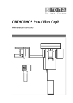
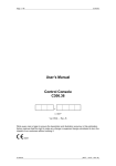
1.2 Control panel
..
10
/
.
/0
0
!"#
$ % "& '! #' ( # "# "% '(
#' !")
*
+(' !
* #'
"% '(
#"& " #! #'"
'$
, %-
In the rest of the manual the above image is referenced by the button and display
identifying number or letter. For example (8), (B).
LCD display layout
Manual parameter setting
Heat being
stored in X-Ray tube
Cooling time
Ready for use
Error / information
display
Other settings
Other fluoro settings
Fluoroscopic X-Ray
tube voltage
Fluorocsopic X-Ray tube
current
Actual fluoro settings
6
TOP-X100NR USER MANUAL
Innomed Medical Inc.
2. Turning the generator on and off
Turn the generator on with the ON button (1) and off with the OFF button (2). The
LED above the ON button indicates when the generator is on, and the LED above
the OFF button indicates when it is off, but the input mains presented.
When turning the generator on a process starts during which the control panel, the
X-ray controller, and the generator controlled parts are placed under voltage. As a
first step the generator performs a self-test procedure.
Parameters may be set after the default settings (80kV, 100mA, 100ms) appear on
the LED displays (B, C, D).
Exposure can be started when the main contactor is on and READY appears on the
panel LCD (A).
7
TOP-X100NR USER MANUAL
Innomed Medical Inc.
3. Load limits, writing a log file
The generator takes the load-limit of the parts into consideration in all operating
modes and does not allow the use of settings that can damage the generator or the
X-ray tube.
The generator considers the following limits:
• The maximum allowed anode voltage (kV) value of the generator.
• The maximum allowed anode current (mA) value of the generator.
• The maximum allowed power (kW) value of the generator.
• The maximum allowed current – time product (mAs) value of the generator.
• The maximum allowed anode current (mA) value of the X-ray tube for both focal
spots, considering anode rotation speed.
• The maximum allowed anode voltage (kV) of the X-ray tube.
• The maximum allowed power (kW) of the X-ray tube for both focal spots,
considering the anode rotation speed and the set exposure time.
• The input heat from rotation and from exposures, and the cooling period,
considering the thermal energy in the anode and in the housing. This is calculated
exactly even if the generator is turned off and turned back on much later. This is
called the “heat unit (HU) calculation”.
• The cooling period of the “track” – the anode’s most loaded part during exposure.
This is called ”wait time”.
To prevent overload, the HU value is always displayed on the top right corner of the
control panel’s LCD (A). It indicates the calculated amount of heat that would be
stored in the tube, as a percentage of the total load-limit, if the exposure with the
currently set parameters was made. As the tube cools, this value decreases.
Do not perform exposure as long as the HU value is over 100%,
because it will overload the tube!
A slowly decreasing line will appear after every exposure next to the HU value with
the word WAIT. This indicates the cooling period of the anode track.
Do not perform exposure until the word WAIT disappears, because
it will overload the tube!
For both of the above cases exposure is not disabled.
It is the operator’s responsibility to decide whether to make
exposure contrary to the warning. The generator records
exposures made with overloading in a separate log-file!
8
TOP-X100NR USER MANUAL
Innomed Medical Inc.
The generator logs all exposures. All exposure data (date, time, set / measured
values) are stored. Three logs are created:
Normal exposures:
This contains all perfect exposures. Its capacity is approximately 600 exposures.
Faulty exposures:
This contains the data of exposures that end with fault-message. Its capacity is
approximately 300 exposures.
Overloaded exposures:
This contains the exposures that had HU value over 100% at the moment of
exposure, or the WAIT time did not reach zero. Its capacity is approximately 300
exposures.
A PC based service program can be used to view the logs. If any of the logs are full,
the oldest exposure’s data is deleted, overwritten with the newest ones.
9
TOP-X100NR USER MANUAL
Innomed Medical Inc.
4. Errors
4.1 Error display
In case of an error a text is shown on the top right part of the console display to
inform about the type of the error and a code which identifies the error more precise
for a qualified person.
If the operational state of the generator changes the top left script of "READY" shows
the new state.
4.2 Error acknowledgement
In case of any error it can be cleared by pushing any button on the console or on the
fluoro remote controller. In case of an error causing “safe mode”, the error display
can be cleared, but the exposure remains disabled. Another exposition can only be
made after turning the generator off and on again.
4.3 Types of errors
The errors are grouped by their fatality.
The "READY" script on the console display means that no error happened disabling
the generator operation, so the generator is ready for use.
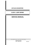
4.3.1 Limit control
The warnings displayed when reaching the load limits of the X-Ray tube or the
generator are only for information. E.g.: Reaching the current-time product (mAs)
limit of the generator:
The generator remains ready for use, the "READY" script does not change.
4.3.2 Warnings
Warnings are errors detected by the generator that do not influence the operation
from the standpoint of the user, but are logged. E.g.: Pushing an exposure button
that is unusable according to the current configuration.
10
TOP-X100NR USER MANUAL
Innomed Medical Inc.
The "READY" script changes to "WARNING".
4.3.3 X-Ray interruption, inhibition
These error disable the exposure and preparation. In case of such an error the
exposure in progress is interrupted. Mostly caused by a system state that is
dangerous to the generator or the connected equipment or makes the further use
impossible. E.g.: No current on the selected filament.
The "READY" script changes to "ERROR".
4.3.4 Safe mode
Gross errors, the high power parts of the generator must be deenergised in order to
avoid damage. E.g.: Communication with the fluoro remote controller is interrupted
11
TOP-X100NR USER MANUAL
Innomed Medical Inc.
The "READY" script changes to "SAFE MODE".
4.3.5 Turn off
Gross errors, the high power parts and the control of the generator must be
deenergised in order to avoid damage. In case of such an error the generator turns
off, the error can not be displayed.
The error can only be read from the log file by a PC-based installation software.
4.4 Log file
All the errors are stored in a log file. The time of the error and its code is stored. The
log file can be read by a PC based installation software.
4.5 Service contact
Please contact the nearest service in case of errors which make the use of the
generator impossible, or are not caused by improper use.
Please inform the service person about the code of the error which is located after
the name of the error in round brackets.
E.g.: Remote comm. error (98;0)
4.6 Basic errors
A list of errors that can appear during normal operation
Error code
(1;1), (1;2)
(2;1)
(3;1)
(4;1)
(18;1)
Description
The tube is overheated by load. Wait until it cools.
Preparation button pressed during tube change. Wait a few seconds
with preparation after device change.
Check the tube positioning (Device interlock missing)
The examination room door is open.
The maximum fluoro time is reached. Reset the time counter.
12
TOP-X100NR USER MANUAL
(20;1)
(25;1..512)
(37;0)
(47;0)
(51;0)
(55;0)
(56;0)
(70;0)
(71;0)
(76;0)
(106;0)
(119;0)
(122;0)
(137;0)
Innomed Medical Inc.
The tube is overheated by load. Wait until it cools.
Error of the power unit during exposure. If regularly happens contact
the service.
The set time for tomo exposure was too short.
The set mAs value for the AEC-controlled exposure was too little
Prep button released during preparation.
The generator is overheated by load. Wait until it cools.
Exp button released during exposure
The ionization chamber has not received sufficient amount of X-Ray.
Check the X-Ray parameters set, and that the sensitive areas of the
ionization chamber receive X-Ray properly.
The other exposure button must be used in the current configuration
Preparation longer than 10 seconds
Attempt to start a tomographic exposure, but the tomo mode was not
selected on the device (there is no tomo-ready signal from the device)
Exp button not released 10 seconds after exposure
Too little mAs set for an AEC controlled exposure. Check the set XRay parameters.
The external device (image processor, PC) is not turned on or is not
ready receiving X-Ray. (Waiting for ready signal on the serial line)
13
TOP-X100NR USER MANUAL
Innomed Medical Inc.
5. Anatomical program mode
After turning on, the generator starts with the APR operating mode – a low-power
program.
In the APR operating mode of the TOP-X 100NR 12 buttons (9-20) are reserved in
the APR field (A) for the anatomical programs. Each button is an arbitrary level,
independent anatomical program. During installation it is possible to set each field’s
unique name.
When a body part button (9-20) is pushed, the selected body part’s sub-menu is
displayed. Here 12 body parts or sub-body parts selections are available.
When the anatomical program is displayed (sub body part selection including
settings), all program-related settings appear on the control panel displays.
Selecting an anatomical program (APR) always means the automatic setting of the
next parameters (in this example at the “SKULL AP”).
kV:
mAs:
Device (TECHNIQUE):
Grid use (GRID):
High-speed starter (HS):
Tube (TUBE):
Focal spot (FOCUS):
AEC ON/OFF:
Dominant field (FIELD):
Film type (SCREEN):
Density correction (DENSITY):
Patient thickness (PATIENT):
Load (LOAD 100%):
70kV
40mAs
Vertical Bucky stand
Grid is used
Not used
Tube 1
Large focal spot
On
2. (middle) is selected
M medium film sensitivity
"0" (middle setting)
Normal (average) size
Allows max. 80% load
The parameter values retrieved in APR mode are preset to a patient with average
height and weight, but the parameters can be changed anytime.
14
TOP-X100NR USER MANUAL
Innomed Medical Inc.
All changes (fatter/thinner patient, film sensitivity selection, etc.) that modify the
default data are supervised by the generator’s software. It is important to note that
these modifications will set only correct values for the anatomical programs until one
of the following buttons will be used:
kV up/down (34,35), mA up/down (36,37), mAs up/down (36,37), sec up/down
(38,39)
Using these buttons will switch the generator into manual mode, in other words an
operating mode with free parameter setting (see section 2.2). In this case all
parameters can be changed freely within the limits of the tube and generator.
Use the APR/SET
button (8) to return to the main APR menu.
After exposure the console returns to the last used sub-body part menu. If you would
like to return to the upper body part selection, push the APR/SET
again.
15
button
TOP-X100NR USER MANUAL
Innomed Medical Inc.
6. Automatic exposure control (AEC)
6.1 The AEC operating mode
When using the AEC operating mode, the so-called ionization chamber placed
between the patient and the film performs the in time exposure stoppage. The
ionization chamber measures the dosage passing through it and stops exposure
when the dosage required for the optimal darkening of the used film is reached.
AEC can be used in both APR and manual mode, but only if AEC mode is configured
for the given examination device. In both cases the AEC function can be turned on or
off according to user preference. In APR mode, depending on body part related
programming the program starts either with or without AEC. The LEDs above the
AEC field buttons (25-27) indicate which fields are used. If any of the three LEDs are
on, the device is operating in AEC mode.
The AEC dominant field buttons (25-27) determine which part of the image is
considered important; while the DENSITY (density correction) buttons (12, 18) let
you set whether to make the image darker or lighter than usual.
In AEC mode the time (sec) or current-time product (mAs) parameters on the RAD
parameter displays (C, D) only indicate the maximum value the generator will allow
during exposure. If this exposure time value or the mAs value is reached during
exposure, the generator will turn off exposure. These are the so-called backup
values. These are protections in case the AEC function is not operational. This can
happen, for example, if X-ray radiation does not reach the ionization chamber,
because the collimator setting is not appropriate.
If the AEC function did not stop the exposure but reaching either the set time or the
set mAs value, the generator displays an error message at the end of the exposure,
warning that the film will most likely be too light. In this case the error message
remains and exposure is disabled until the user pushes any of the buttons on the
console to acknowledge it.
The two backup values have to be set according to the expected mAs value within
the current conditions (FFD, patient size, etc.) and at the given tube voltage (kV).
6.2 AEC operating mode setting possibilities
You can access AEC operating mode by selecting one or more of the AEC dominant
fields (25-27).
The LED over the selected field’s button turns on
and the DENSITY field appears on the LCD display (A). The mentioned field is not
accessible in other operating modes. Setting the dominant fields does not affect the
recording parameters.
16
TOP-X100NR USER MANUAL
Innomed Medical Inc.
When using AEC, prior to the exposure mAs or sec backup values must be set on
the LED displays (B, C, D) according to the examination. The measured values after
exposure appear floating on the LCD display.
6.2.1 DENSITY – density correction
Density can be set in seven steps in the field (12, 18), which effects the darkening of
the image on the film. The higher the density correction value, the darker the image
will be. The seven values change the dosage value of terminating the exposure
compared to the default value (0) reaching the film:
-3
-2
-1
0
+1
+2
+3
50%
63%
80%
100%
125%
160%
200%
6.2.2 SCREEN – screen selection
Three screen types are available (13, 19). These are usually the following:
• High speed
• Medium speed
• Detailed
high-sensitivity, but more coarse resolution
medium-sensitivity, medium resolution
low-sensitivity, but high resolution, rich in detail
The high-sensitivity screen / film combination requires less dosage, but the resulting
film resolution is lower. The lower sensitivity requires a higher dosage, but the film
quality and resolution is very good.
The user decides what type of screen and film to use considering the examination
characteristics and other conditions. H, M or D type is set accordingly on the console.
The generator automatically corrects the mAs value according to the selection of the
film / screen combination sensitivity. Since there are numerous film and screen types
available in the market, and their sensitivity is variable, the sensitivity values for H, M
and D must be set during generator installation.
This is performed by the installing professional based on the cassettes used at the
workstation. Based on the cassettes, i.e. the used screen / film systems the installing
professional assigns sensitivity values to each of the H, M, D signs (based on the
nominal sensitivity set at 80kV). This way it is easy to reconcile the H/M/D marking
on the control panel with the type indicated on the cassettes.
17
TOP-X100NR USER MANUAL
Innomed Medical Inc.
Selecting the correct screen type on the control panel in AEC mode
is extremely important, because when determining the required
dosage, the generator takes into account the selected film / screen
sensitivity as well.
6.3 Verifying the exact operation of the AEC
Make an exposure using AEC. Make sure the film has the same sensitivity as the
film used for calibration during installation. Set 80kV and beam current that result in
radiation period longer than 50ms and shorter than 1s. Place a 15cm water phantom
in the radiation’s path.
After development compare this film to the film made during calibration. The optical
density can only deviate by 0.15 between the two films.
18
TOP-X100NR USER MANUAL
Innomed Medical Inc.
7. Parameter setting in manual operating mode
Free parameter setting means that any of the four parameters effecting X-ray quality,
strength and duration can be set freely – within the operating limits of the tube and
the generator, and the device’s allowed accuracy.
The four parameters are the following:
- Ua (the voltage between the X-ray tube anode-cathode, kV)
- Ia
(the current flowing through the X-ray tube, mA)
- Te (the time until the tube current exists, ms or s)
-Q
(Ia x Te : the product of tube current and time, mAs)
Pushing the APR/SET button
(8) or the buttons that directly set the
parameter values (kV, mA, mAs, sec) in anatomical program mode accesses free
parameter setting, also known as manual mode. In manual mode the settings are
only limited by the generator power and the tube specifications.
Use the MODE
button (33) to switch between two- and three-point modes.
Three-point mode is the operating mode when the voltage (kV), current (mA) and
time are set. The generator calculates the current – time product (mAs), but does not
display it on the exposure parameter display. To make it visible, push the MODE
button (33) once.
To make the related current (mA) and time values visible in two-point mode (or mAs
mode), push the MODE button
again.
The basic principle of exposure parameter setting is that exposure quality is
generally affected by two factors: X-ray tube voltage (kV) and the current – time
product (mAs). With a given mAs value the X-ray tube current (mA) and exposure
time values are secondary. The only special exceptions to this are a few special
cases, for example tomography or very short exposures. For this reason the
generator, in case of some user selection, can change the current (mA) and time
parameters while leaving the mAs value unchanged.
Following is an example of this feature.
Let us assume that the X-ray tube limit is 48kW at large focal spot and 20kW at
small focal spot at 0.1s exposure time. Enable maximum load (LOAD 100% field).
Set 120kV voltage, 400mA current (this will be 48kW) and 0.1s exposure time.
Switch to two-point mode, 40mAs is displayed. Switch to small focal spot. The small
focal spot cannot handle the 48kW load, so the generator recalculates the current
and time parameters, leaving the X-ray tube voltage (kV) and the mAs values, thus
decreasing the load below the allowed limit. Switch back to three-point mode. The
new indicated values are: 120kV, 125mA (15kW), 0.32s (40mAs). At this example we
19
TOP-X100NR USER MANUAL
Innomed Medical Inc.
have to mention that the X-ray tube load (kW) depends on the exposure time. The
previous values are correct because with 0.32s exposure time the X-ray tube can still
be loaded with 15kW.
The similar cases will be apparent in the following.
7.1 Radiation parameter setting
7.1.1 Setting exposure X-ray tube voltage (kV)
Use the kV up (35) and kV down (34) buttons to set this value. Pushing and holding
these buttons continuously changes the value between the allowed limits in 1kV
steps.
The X-ray tube voltage value appears on the kV display (B). Changing this value
does not effect the mAs value, only the tube load changes. With increasing kV
values, this results in decreasing maximum mA setting.
7.1.2 Three-point mode, mA / ms setting
Using the mA up (37) and mA down (36) buttons changes the mA value. Changing
the mA value happens in preset steps.
Warning: When changing mAs, mA does not change according to the preset steps
because in those cases the time step is determining and mA is determined by the
generator by dividing mAs by time. For this reason it is normal when the mA value is
for example 273mA. Using the mA up / mA down buttons the generator again selects
the mA value by the mA step.
mA steps [mA]:
10, 12, 16, 20, 25, 32, 40, 50, 63, 80, 100, 125, 160, 200, 250, 320, 400, 500,
630, 800
The maximum value for the TOP-X 100NR family is 800mA.
Using the SEC up (39) / SEC down (38) buttons changes the exposure time (ms/s)
value. In cases of longer exposure times the generator and tube mA / kV load is less.
The generator limits the adjustable exposure time accordingly.
20
TOP-X100NR USER MANUAL
Innomed Medical Inc.
Time steps [ms or s]:
1, 2, 3, 4, 5, 6, 8, 10, 12, 16, 20, 25, 32, 40, 50, 63, 80, 100,
120, 160, 200, 250, 320, 400, 500, 630, 800 ms,
1, 1.2, 1.6, 2, 2.5, 3.2, 4, 5, 6.3, 8, 10 s
7.1.3 mAs mode (or two-point mode)
Using the mAs up (37) / mAs down (36) buttons changes the mAs value. The kV
value will not change, but the mA and time parameters will. According to exposure
parameters the generator will try to keep the exposure time around the value set at
installation (typically 100ms), if load and current limits make it possible. When
pushed and held down, the mAs value increases according to the following steps:
mAs steps [mAs]:
0.5, 0.6, 0.8, 1, 1.2, 1.6, 2, 2.5, 3.2, 4, 5, 6.3, 8, 10, 12, 16, 20, 25, 32,
40, 50, 63, 80, 100, 125, 160, 200, 250, 320, 400, 500, 630, 800, 1000
7.1.4 PATIENT – Patient size
Patient size is mainly used to correct parameters set in APR mode.
If the patient is fatter or thinner than average, or the patient is a child, use one of the
patient buttons (21-24). In this case you can see that the exposure voltage (kV)
changes; when the child button is used, mAs also changes (increases in case of
fatter patient, decreases in case of child or thinner patient). The other parameters
remain unchanged. The buttons have the same functions in free parameter setting
operating mode as well.
If the required change cannot be set due to load limits, the LED indicating patient
size does not turn on, and the previous selection remain.
21
TOP-X100NR USER MANUAL
Innomed Medical Inc.
7.2 Examination device, X-ray tube and focal spot selection
7.2.1 TECHNIQUE – examination device
You can select five examination devices in the device selection field (3-7) if they are
configured during installation. In APR mode each program is assigned to a device.
The LEDs above the buttons indicate which examination device is selected. Pushing
any of the device selection buttons exits the generator from APR mode and turns to
manual operating mode.
Symbols on the buttons in the device selection field indicate the devices. One of
these is AUX, reserved for special devices (for example digital spotfilm device).
7.2.2 BUCKY – grid symbol
Use this button (31) to select whether you would like to use the device with or without
grid. Exposures without a grid require lower kV and decreased mAs due to the
decrease of filtering; the generator automatically changes these values in APR
mode.
7.2.3 HS – high-speed
If the generator has a high-speed starter and the HS mode is configured for the
selected device, the button with the HS symbol (30) is used to select one of two
anode rotating speeds: normal rotation and high-speed rotation. If the LED is on,
high-speed is selected.
The use of the high-speed starter results in the following:
- more power from the tube,
- higher tube current is allowed, so the exposure takes less time.
If special high power is not needed for a given examination, it is recommended to
use normal rotation, saving the tube and increasing its lifetime.
22
TOP-X100NR USER MANUAL
Innomed Medical Inc.
High-speed rotation can be turned on with any exposure parameter settings. It can
only be turned off if the current settings do not overload the tube at normal speed.
7.2.4 FOCUS – X-ray tube focal spot
Use this button (32) to select one of the usually two possible X-ray tube focal spots
you would like to use:
• Small focal spot
Results in a sharper image, but cannot be loaded as much as large focal
spot and takes higher thermal stress for the anode plate.
• Large focal spot
Results in a less sharp image, but can be loaded more than small focal
spot.
Selection depends on the parameters required for the examination and X-ray tube
load ability. Of course the generator takes into account the applied X-ray tube’s load
ability, so it does not allow to set any parameter combinations that exceed the limit
values.
During exposure parameter setting the generator automatically sets the appropriate
focal spot. Manual switching is only possible if the set parameters are allowed at
both focal spot settings.
In mAs mode when using the FOCUS button if the selected parameter combination
is not allowed with the selected focal spot, the generator will try to recalculate the
current (mA) and time (s) values without changing the mAs value. In this case the
mAs and the kV values are not changed.
In three-point mode manual focal spot selection is only possible in a very small
parameter range.
A LED over the button indicates the focal spot selected for the exposure.
7.2.5 Automatic selection of large focal spot and high-speed rotation
The X-ray image quality is better if the exposure is made on small focal spot. The Xray tube can sustain larger loads at large focal spot or high-speed. During increasing
the load the generator automatically switches to large focus or high speed for larger
load ability.
In the configuration you can set whether the generator should first try to switch to
large focal spot or high-speed. If you select keeping small focal spot, the advantage
is a better resolution image. If you select keeping normal speed, the advantage is
less load on the anode and less heat transmitted into the tube.
23
TOP-X100NR USER MANUAL
Innomed Medical Inc.
7.2.6 TUBE – X-ray tube
The X-ray tube cannot be selected directly, only indirectly through device selection.
During generator or system installation the X-ray tubes for each examination device
has to be set. The currently selected X-ray tube is indicated by the number 1 or 2 at
the top of the LCD display.
7.3 RADIATION - Preparation, exposure
If the settings are acceptable an exposure can be made with the buttons in the
RADIATION field (29, 29) or optionally with the two-state external hand-held
exposure switch. Pushing the PREP button prepares the generator. When
preparation is done, the PREP symbol (E) turns on and the exposure can be made
with the button marked EXP in 9 seconds. The preparation period is usually between
1 and 2 seconds, set during the installation of the generator according to the applied
X-ray tube and examination device.
You can also make an exposure by pushing and holding the EXP button. In this case
the generator makes the exposure immediately after preparation finished.
Warning: The exposure button must be held down during the full time of the
exposure process. If you let the button up before the exposure is finished, the
exposure immediately aborts and the control panel displays an error message.
24
TOP-X100NR USER MANUAL
Innomed Medical Inc.
8. Fluoroscopic mode
8.1 Controls on the fluoroscopic controller
8.2 Power on
When turning the generator on (see chapter 2) the Innomed logo appears on the
display (A) and the controller loads the character sets needed for display; a status
line at the bottom of the screen indicates the current status. The main screen only
appears after the generator has turned on completely.
25
TOP-X100NR USER MANUAL
Innomed Medical Inc.
If, for whatever reason, there is no connection between the generator and the
controller, the following window appears on the screen. Here you can also set screen
contrast (2, 7), backlight brightness (1, 6) and beeper volume (3, 8). Use the “save
changes” button to save any modifications.
The demo operating mode is only for demonstration purposes and cannot be
accessed on controllers connected to operating generators. If the controller does not
operate correctly when reconnected to the generator, please contact our nearest
service office.
You can also access the above window during normal operation to set the display
parameters. Press and hold the time reset button (10) (see section 1.4.3) for at least
5 seconds to display this window. Press the button next to “normal mode” (10) to
return to normal mode.
26
TOP-X100NR USER MANUAL
Innomed Medical Inc.
The following appears on the LCD screen (A) after successful power on.
Certain exposure parameters and all fluoroscopic parameters may be set on the
controller.
8.3 Exposure parameters
The set of exposure parameters are similar to those described at the control panel.
Further possibilities are described at chapter 7.1.
8.3.1 Exposure x-ray tube voltage (kV) setting
Use the kV up / kV down buttons (11,12) to set this value. Continuously holding one
of these buttons increases / decreases the value in steps of 1kV within the allowed
limits. The kV value on the control panel’s kV display will be also refreshed.
8.3.2 mAs mode (or two-point mode)
Using the mAs up / mAs down buttons (13,14) changes the mAs value. Continuously
holding one of the mAs buttons changes the value according to predefined steps.
Pushing the mAs up / mAs down button the console is automatically turned into twopoint mode and the new mAs value appears on the mAs display.
8.3.3 AEC dominant field selection
Pushing the button (3) next to the AEC symbol opens a new window on the screen.
27
TOP-X100NR USER MANUAL
Innomed Medical Inc.
Here you can select the desired dominant fields (2, 4, 7) and return to the main
window with the back button (5).
8.3.4 Selecting anatomical program
Pushing the MENU (8), then the APR (7) buttons displays the window containing the
main body parts, the same as on the main operator console.
Similar to the control panel, selecting the appropriate exposure program from the
main and sub body parts returns you to the main window, where you can see the
28
TOP-X100NR USER MANUAL
Innomed Medical Inc.
parameters according to the selected examination. As long as you do not change
these parameters, the APR name is also displayed.
8.4 Fluoroscopic parameter setting
8.4.1 Fluoroscopic x-ray tube voltage (kV) setting
Use the fluoro kV up (11) / fluro kV down (12) buttons to change this value.
Continuously holding one of these buttons increases / decreases the value in steps
of 1kV within the allowed limits. The change of fluoroscopic kV will automatically
change the fluoroscopic mA value as well. The mA value changes are proportional to
the kV. The kV/mA ratio can be modified by changing the mA.
8.4.2 Fluoroscopic x-ray anode current (mA) setting
Use the fluoro mA up (13) / fluro mA down (14) buttons to change this value.
Continuously holding one of these buttons increases / decreases the value in steps
of 0.1mA within the allowed limits. Changing the mA value does not affect the kV
value.
8.4.3 Fluoroscopic time
The timer on the display indicates the accumulated fluoroscopic time and only
operates if radiation emits from the tube. The clock can only be cleared with the
reset (10) button. When exceeding the “beep time” – set during installation – the
program warns the user with a continuous sound that the fluoroscopic time is
exceeding the levels safe for the patient. When reaching the maximum allowed
fluoroscopic time (also set in the installation program) the generator automatically
29
TOP-X100NR USER MANUAL
Innomed Medical Inc.
disables radiation. The examination can continue only after resetting fluoroscopic
timer.
8.4.4 Zoom
This button (4) allows access to the image amplifier’s zoom functions if it is not
controlled from the examination table. You can select from normal up to max. four
magnified image displays (depending on configuration). When magnifying, the
fluoroscopic current automatically increases. The number written into the II symbol
on the LCD is proportional to the selected zoom factor.
8.4.5 Video modes
Further image settings are available in the Video options (8) submenu of the MENU
(8):
30
TOP-X100NR USER MANUAL
Innomed Medical Inc.
It is possible to horizontally (7) and vertically (8) mirror the image or invert the colors
(9). By pressing the buttons next to the symbol, the function changes its state. If it
was turned on than it turns off, and vice versa.
8.4.6 Impulse fluoroscopic operating mode
The reason of this operating mode: it is unnecessary to continuously load the patient
with radiation while the camera providing the video signal on max. 25 images per
second. If radiation is emitted only for a short time at the moment of image storage,
and there is a longer pause until the next storage, the result is a live image similar in
quality to continuous fluoroscopy, but the patient’s radiation dosage is decreased to
a fragment.
You can select impulse operating mode with the impulse button (9). In this case the
current impulse per second value appears over the impulse icon.
31
TOP-X100NR USER MANUAL
Innomed Medical Inc.
In impulse operating mode the generator enables the radiation in synch with the
square signal released by the camera. Even lower dosage is possible by emitting
less than 25 radiation impulse per second, but this will decrease the continuity of
motion. To modify the impulse frequency press and hold the impulse button (9) in
active impulse mode. The frequency will increase or decrease, release the button
when the desired frequency is reached. If you press and hold the impulse button (9)
again, the frequency will change in the other direction. The adjustable impulse
frequency steps are set at installation.
8.4.7 Automatic brightness setting (ABS)
Based on the brightness signal received from the TV chain and independently from
the radiation absorption of the examined organ, the system can display stable image
brightness on the monitor. After you have calibrated the controller with the required
brightness level, push the ABS button (5) to activate this function.
32
TOP-X100NR USER MANUAL
Innomed Medical Inc.
In this case the generator compensates the varying brightness with varying voltage,
the result of which, as mentioned above is the change of fluoroscopic current. In
case of starting with default parameters, the controller can adjust to the required
brightness typically in 1 second.
8.4.8 Digital image storage from fluoroscopic operating mode
In fluoroscopic mode pushing the REC button (15) creates digital images storage.
Image storage settings may be changed in the Spot Parameters submenu (9) of the
MENU (8).
33
TOP-X100NR USER MANUAL
Innomed Medical Inc.
Three different image storage operating modes can be set: single, “burst” and series.
In burst operating mode the generator makes 10 images with the set frequency, than
returns to fluoroscopy mode. In series operating mode the images are made with the
set frequency as long as the REC button is pressed. Obviously one image is made in
single operating mode. The image creation frequency is increased and decreased
with buttons 8 and 9. The adjustable image frequencies are set at the installation
time.
8.5 Fluoroscopic parameter setting on the control panel
All the fluoroscopic parameter setting, which are possible on the remote controller
are also available on the console. Further possibilities are described in chapter 8.4.
8.5.1 Displaying fluoroscopic parameters on the control panel
With the exception of the APR screen, the fluoroscopic parameters are always visible
on the control panel.
On the left side of the display is the x-ray tube fluoro voltage; on the right, the
fluoroscopic x-ray current; and in the center, the other fluoro parameters are visible.
The following parameters appear in the middle box:
Image content inverting
Image horizontal mirroring
Image vertical mirroring
If these symbols appear on the display, they indicate active functions; if they do not
appear, the appropriate functions are disabled.
To the right of these indications is the digital image storage fluoroscopic operating
mode:
Single Spot – Digital storage of a single image
34
TOP-X100NR USER MANUAL
Innomed Medical Inc.
Burst – Digital storage of 10 images.
Rapid – Continuous digital image storage. In this and in the previous mode,
the image creation frequency appears next to the symbol.
The following line contains the accumulated fluoroscopy time.
To the left in the bottom row is the magnification factor. To the right is the symbol
indicating ABS active state. In the center are the different fluoroscopic mode states:
Continuous fluoroscopy
Impulse fluoroscopy. In this operating mode the impulse frequency appears
under the symbol.
8.5.2 Setting fluoroscopy x-ray voltage (kV)
You can set this value on the control panel with the soft buttons next to the fluoro kV.
Use + (13) button next to the symbol to increase the value, and – (14) to decrease it.
Continuously holding the buttons changes the value within the allowed limits in 1kV
steps.
8.5.3 Setting fluoroscopy x-ray current (mA)
You can set this value on the control panel with the soft buttons next to the fluoro
mA. Use + (19) button next to the symbol to increase the value, and – (20) to
decrease it. Continuously holding the buttons changes the value within the allowed
limits in 0.1mA steps
8.5.4 Fluoroscopy time
The clock on the display indicates fluoroscopy time, and only operates when x-ray
emits from the tube. The timer can be reset with the soft button (8) next to the timer
reset symbol. When exceeding the “beep time” value set in the install program during
installation, the control panel warns with a continuous sound that fluoroscopy
duration is nearing what is dangerous to patient health. When reaching the allowed
maximum fluoroscopy time (also set in the install program), the generator
automatically disables the x-ray. The examination can continue only when
fluoroscopy timer is reset.
8.5.5 Zoom
You can access the image intensifier’s zoom functions with this parameter. You can
select among normal and max. four magnified image displays. During magnification
fluoroscopy current is automatically multiplied. To do this, enter fluoroscopy
parameter setting with the “More options” soft button (12).
The following screen appears:
35
TOP-X100NR USER MANUAL
Innomed Medical Inc.
Use the Magnify soft button (15) to set magnification level.
8.5.6 Video modes
Use the Video options menu to invert image content, and to turn image horizontal
and vertical mirroring on and off. Enter this menu with the soft button next to the
Video options (9) label. The following screen appears:
Next to the pictograms on the right side of the screen is the state of the appropriate
functions. If you push any of the soft buttons next to them (15) (16) (17), the function
state changes. So if it was on, it changes to off, and vice versa.
8.5.7 Impulse fluoroscopy operating mode
To set impulse operating mode you have to enter the menu with the soft button next
to the Pulse fluoro options (10). The following screen appears:
36
TOP-X100NR USER MANUAL
Innomed Medical Inc.
Use the soft button (9) next to the Fluoro mode label to turn impulse operating mode
on and off. By selecting less than 25 x-ray impulses per second lower dosage is
available, but only at the expense of image continuity. To modify impulse frequency,
push the soft buttons (10), (16) next to the Pulse frequency label in active impulse
operating mode. Frequency begins to increase if you push the button on the right
(16), and decrease with the button on the left (10). Release the button when the
desired frequency is reached. The available impulse frequencies are set at
installation time.
Push the back button (12) to exit from this menu.
8.5.8 Automatic brightness setting (ABS)
This function can be activated by pushing the soft button next to the ABS script (16).
8.5.9 Digital image storage from fluoroscopy operating mode
Push the button next to the Spot options (11) label to enter image storage settings
menu.
37
TOP-X100NR USER MANUAL
Innomed Medical Inc.
Three different image storage operating modes can be set: single, “burst” and rapid.
In burst operating mode the generator records ten images at the set frequency, then
returns to fluoroscopy. In rapid mode the recordings are also made at the set
frequency, but during the full time the REC button is held down. In single mode one
record is made. Recording mode is set with the soft button next to the Spot mode
label (9). Image recording frequency is increased or decreased with the soft buttons
(10), (16) to the right and left of the Spot frequency label. The available image
frequency values are set at installation time.
38
TOP-X100NR USER MANUAL
Innomed Medical Inc.
9. Cleaning and maintenance
If necessary, the generator (including the control panel) cover may be cleaned
according to the following.
Before cleaning completely power down the generator, including
mains power and all other devices electrically connected to the
generator. After power down wait at least 10 minutes.
Clean the four side and the top cover’s external parts with a soft cloth slightly wet
(but in no way dripping wet) with weak, diluted cleaning substance (for example
dishwasher). Do not use alcohol, ether, thinner or any other solvents or chemicals.
Make sure none of the cleaning substance or water flows or splashes into the device
and that none of the cleaning substance remains on the surfaces. Take care that
none of the signs and labels on the surfaces are damaged and they remain visible
and legible. Allow the surfaces to dry completely, but wait at least 15 minutes before
turning the device back on.
The generator requires regular maintenance performed by the professional service
as detailed in the installation manual.
39
TOP-X100NR USER MANUAL
Innomed Medical Inc.
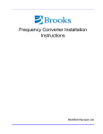
10. Technical data
#
.2 ' ' % 3 .2 ' ' % %4&
Modell
Maximum anode current
in radiological mode
350HF
450HF
550HF
650HF
850HF
@ 80kV
300 mA
400 mA
500 mA
600 mA
800 mA
@ 100kV
300 mA
320 mA
400 mA
500 mA
630 mA
@ 150kV
200 mA
200 mA
250 mA
250 mA
320 mA
Maximum anode current in fluoroscopic
mode (40-125kV)
Maximum anode current in radiological
mode
(X-Ray tube voltage)
X-Ray parameters resulting the maximum
output power in radiological mode
X-Ray parameters resulting the maximum
output power in fluoroscopic mode
Maximum output power
(parameter combinations)
/
6.2
10mA
300 mA
(100kV)
400 mA
(80kV)
500 mA
(80kV)
600 mA
(83kV)
800 mA
(81kV)
100kV,
300mA
80kV,
400mA
80kV,
500mA
100kV,
500mA
103kV,
630mA
50 kW
(100kV,
500mA,
100ms)
65 kW
(103 kV,
630mA,
100ms)
125kV, 10mA
30 kW
(100kV,
300mA,
100ms)
,
32 kW
(80kV,
400mA,
100ms)
40 kW
(80kV,
500mA,
100ms)
'5 6
5
40
TOP-X100NR USER MANUAL
"78%9
",
:
Innomed Medical Inc.
:
,
"78%9
;)
2 8;
<
,
"78%9
*
;)
2 8;
2
6
;)
!
",
3
: !
+ #
= !
!
&
,
/
3
,
!
;)
!
>
"78%9
,
:
.2 '''%$%
?
=
.2 '''%$%$
+
,
/
41
,
!
+
!
,
,
+ =,
+%
TOP-X100NR USER MANUAL
"78%9
",
:
Innomed Medical Inc.
:
,
"78%9
± =?
,
#
. -& ± 1 =?
.2 '''% %
±
±
=?
!
=?
±
±
0
.2
'''% %
.2
'''% %5
?
,
3
±
±
=?
!
=?
=?
±
=?
=?
±
=?
A 5@ B"
#
C(5@
'5 !
+
0
)
A 5@ B"
B"& #
C(5@
'5 !
:
:
+
!
.2
'''% %
8+
#
5'0 '
>
&
B"&
'@ B"
# '@
5 !
B"&
4'@ B"
#
$'@
5 !
B"&
4'@ B"
#
$'@
5 !
B"&
A 5@ B"
B"& #
C(5@
5
$ 60
,
,
+
B"&
8+
>
!
,
:
!
!
,
.2
'''% %1
,
:
/
B"
, 62
:
,
42
3
:
+ ,
! ,
3
,
: ,
! ,
$'@
+
+ >
! ,
,
!
,
0
:
+ >
! ,
,
!
,
:
+ >
! ,
B"&
,
!
,
:
'@ B"
# '@
5 !
A 5@ B"
#
C(5@
5
! $ 60
+
,
± =?
± 1 =?
.
.
,
:
TOP-X100NR USER MANUAL
"78%9
",
:
Innomed Medical Inc.
:
,
"78%9
,
+
,
,
8
;)
>
,
"78%9
3
;)
'''% %
;)
'''% %$
$ ?;
5' = D 1'
$ ?0
1'
D 5<
,
,
,
>
>
2
.2
;
.2
!
3
,
!
$?
E 1.2 ⋅
$ ?0
E 1.2 ⋅
,
P
P 1'
E 2.3 ⋅ P 1''
F,
+
+
,
D 1''
D
5<
*
,
#
F&
,
,
# &
)
,
3
*
,
,
:
>
!
!
:
!
+ ,,
/7".
/7".
6 1'
",
)
7:
1''
,
,
*
3, , ,
>
!
!
3 G
3
,
3
,
!+ ,
3
+, , "78%9
,
:
!
36
! "
:! ,
*
: !
!3
,
>
1'
!
5' =
;)
!
: !3
,
,
>
+
,
=
!
!
.
!
#
)
,
0
&
"?
:
,
;)
,
:
"78%9
3
,
43
,
,
,
$ ?0
* ;)
,
,
: 3"78%9
: 3
TOP-X100NR USER MANUAL
Innomed Medical Inc.
!
"
#
$%&'
"78%9
:
+,
"78%9
2
,
:
;)
>
#
&
+
3,
) *
>
+
,
+
"78%9
"78%9
*
!
+
+ !
(
#
!
+ ,-. / )-. / )-. /
F
E 1.2 ⋅
'
' $1
''
'
'
''
,
$1
+
!
!
/7".
/7".
6 1'
",
E 1.2 ⋅
'
' $1
P
P
,
3
,
3, , ,
>
!
!
3 G
:
!3+,
+
#
F&
)-. 01
+ -.
E
2.3 ⋅ P
' $
' 4$
$
4$
$
# &
$1
>
1''
)-. /
*
+
!
.
44
!
TOP-X100NR USER MANUAL
Innomed Medical Inc.
11. Disposal of Old Electrical & Electronic Equipment
(Applicable in the European Union and other European
countries with separate collection systems)
",
,
!
,
,
,
>
45
,
,
,
!
=
,
:
,
,
+