1
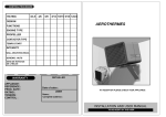
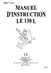
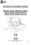
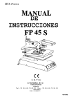
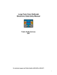
SEFA
®
France
S.E.F.A
Z.I PASTABRAC - B.P 44
11260 ESPERAZA
FRANCE
Tel :33 (0)4.68.74.05.89 - Fax :33.(0)4.68.74.24.08
E Mail : contact@sefa.fr
Page N° 0
SEFA
®
France
I.
CONDITIONS OF GUARANTEE
•
The guarantee period starts the day of putting the equipment into service at the user’s place, for a duration
of one year and for a common use of 8 hours per day.
•
The guarantee is strictly limited to our equipments, against the defects of matter and execution, with the
buyer’s responsibility to prove the known defects.
•
Our responsibility is limited to the obligation to rectify or replace free of charge the parts acknowledged as
faulty by ourselves, and there will no claim for any indemnity whatever the reason given.
Parts replaced under the guarantee:
•
•
remain our property
are the subject of an invoicing of deposit
A credit of cancellation is activated as soon as the faulty parts are returned. The return will have to occur ONE
MONTH MAXIMUM after the intervention.
THE GUARANTEE DOES NOT COVER:
•
The retail consumables such as:
fuses, bulbs, transformers, joint, flexible devices…
•
The supplies, which are not our own manufacturing, undergo the guarantee of their manufacturer.
THE GUARANTEE DOES NOT APPLY:
•
To replacements, nor repairs which would result from normal wear and tear of apparatus and machines, of
deteriorations and accidents coming from negligence, defect of monitoring and maintenance, defective use or
modifications without our written agreement.
•
In case of vice coming from the material supplied by the buyer, or a design imposed by the latter.
•
To repairs which would result from deteriorations or accidents occurred during transport.
•
To operations of maintenance and adjustments inherent in the use of the machine, and indicated in the
maintenance manual, such as:
adjustments of intermediaries, screwing of piping, etc...
does not enter the clauses of guarantee.
For any technical information or spare part order:
Direct Tel N°: 04.68.74.79.54
Page N° 1
SEFA
®
France
II.
INDEX
I.
CONDITIONS OF GUARANTEE................................................................................................................................1
II.
INDEX.............................................................................................................................................................................2
III.
SPECIFICATIONS........................................................................................................................................................3
IV.
INSTALLATION OF THE MACHINE.......................................................................................................................4
1.
2.
HANDLING.....................................................................................................................................................................4
INSTALLATION.............................................................................................................................................................4
V.
PARTS SUBJECTED TO WEAR AND TEAR ..........................................................................................................4
VI.
GENERALITIES ...........................................................................................................................................................5
VII.
SECURITY .....................................................................................................................................................................5
VIII. TIME/TEMPERATURE SETTING ............................................................................................................................6
1.
2.
IX.
TEMPERATURE SETTING (See instruction manual REG 2000) .............................................................................6
TIME SETTING (See instruction manual REG 2000) ................................................................................................6
PRESSURE ADJUSTMENT : ......................................................................................................................................6
a.
b.
X.
Mechanic adjustment....................................................................................................................................................6
Pneumatic adjustment ..............................................................................................................................................6
MAINTENANCE ...........................................................................................................................................................6
1.
2.
3.
4.
5.
Code R1 :......................................................................................................................................................................6
Code R2 : .....................................................................................................................................................................6
Code R3 : .....................................................................................................................................................................6
Code R4 : .....................................................................................................................................................................6
Code R5 : .....................................................................................................................................................................6
XI.
DESCRIPTION OF THE CYCLE ...............................................................................................................................7
XII.
ACCESSORIES FITTING............................................................................................................................................7
LOWER PLATES OF VARIOUS FORMATS .......................................................................................................................7
CARRIAGE FOR WORK IN MASKED TIME......................................................................................................................7
XIII. POSSIBLE BREAKDOWNS........................................................................................................................................8
1.
ELECTRIC BREAKDOWNS ........................................................................................................................................8
XIV. ELECTRIC DIAGRAM ................................................................................................................................................9
XV.
PNEUMATIC DIAGRAM ..........................................................................................................................................11
XVI. MAINTENANCE LOG ...............................................................................................................................................13
XVII. NOTES .........................................................................................................................................................................14
Page N° 2
SEFA
®
France
III. SPECIFICATIONS
Poids en ordre de marche / Weight in running order
70 Kgs
Hauteur / Height
425 mm
Profondeur / Depth
805 mm
Largeur / Width
406 mm
Dimension du plateau / Dimension of the heating plate
400 x 500 mm
Alimentation électrique / Electric power supply
220 V Monophased + earth 50/60
Hz
Puissance / Power
2 250 W
Ampérage / Ampérage
10 A
Régulateur électronique de température à affichage digital / Thermoregulator
Précis à / Accurate to
+/- 1%
Réglable de / / Range of control
0 to 255 °C
Minuterie électronique multigamme / Timer
Précis à / Accurate to
+/- 2%
Réglable de / Range of control
0 to 255 sec
Non contractual document : according to the technical progress, we reserve the right to modify the characteristics of our products.
R
Page N° 3
SEFA
®
France
IV. INSTALLATION OF THE MACHINE
1. HANDLING
Unpack the machine from its box.
Place it on a stable table.
2. INSTALLATION
After having positioned the machine on its working place,
•
Electrically plug the press ( 220 Volt + Neutral + Earth / 50 or 60 Hertz )
V.
PARTS SUBJECTED TO WEAR AND TEAR
On any order : precise the description, the reference and the quantity
Description
Reference
Ref Plan
Quantity
ELECTRIC & PNEUMATIC EQUIPMENT
CAR-357
ELECTRONIC CARD
1
ECR-360
SCREEN
1
CLA-371°
KEYBOARD
1
RES-181
HEAT ELEMENT 100X100
9
VER-128
JACK D=80 C=240mm
1
DIS-125
DISTRIBUTOR P/R 1/8
1
SON-188
T° SENSOR
1
PRESS COVER
MOU-540
RUBBER 9 MM
Page N° 4
400 X 500 MM
SEFA
®
France
VI. GENERALITIES
Option
Sleeve-board
Pressure adjustment
button
Heating plate
Option
Logo board
Pressure
indicator
Option
Lateral carriage
T° regulator
Timer
Silicone
rubber
On - Off
Emergency
stop
Fuse
Lowering plate
buttons
This heat seal press was designed to carry out a production while respecting article L 233-5 of the labour laws, to
ensure the user’s security.
Thsi press was designed for an operator working opposite the machine.
VII. SECURITY
Any maintenance intervention has to be done
when the machine is off and locked
(electric energies unplugged)
Page N° 5
SEFA
®
France
VIII.
TIME/TEMPERATURE SETTING
1.
TEMPERATURE SETTING (See instruction manual REG 2000)
2.
TIME SETTING (See instruction manual REG 2000)
IX. PRESSURE ADJUSTMENT :
-
The pressure adjustment can be modified according to the need of the user:
a. Mechanic adjustment
In that case the operator can modify the pressure adjusting the heating plate height.
He has to use the wheel which is on the arm holding the plate.
Clockwise, he will obtain more pressure.
Anticlockwise, he will obtain less pressure.
b. Pneumatic adjustment
The operator will have to operate on the pressure regulator which is on the left side of the machine,
In screwing the regulator button, he will increase the pressure (the manometer hand will
indicate a value higher than the one displayed previously)
In unscrewing the regulator button, he will decrease the pressure (the manometer hand will
indicate a value lower than the one displayed previously)
X.
MAINTENANCE
1. Code R1 :
•
Appear when the machine has been heating for 9 300 h that is to say about 5 years
♦ It will be necessary to carry out a general service. See your retailer.
2. Code R2 :
•
Appears when the machine has realized 60 000 knocks
♦ It will be necessary to grease the axles, oil and lubricate all the moving parts.
3. Code R3 :
•
Appears when the machine has realized 240 000 knocks
♦ It will then be necessary to change the pads(silicone rubber)
4. Code R4 :
•
Appears when the machine has realized 30 000 knocks
♦ It will be necessary to grease the axles.
5. Code R5 :
•
Appears when the machine has realized 600 000 knocks
♦ I twill be necessary to change the jack’s joints which ensure the plate movement and pressure.
TO DELETE THE MESSAGE REGARDING THE SERVICE:
REFER TO THE USER MANUAL REG 2000
Page N° 6
SEFA
®
France
XI. DESCRIPTION OF THE CYCLE
1.
The operator will have to action the main switch to power up the machine
2.
Set the temperature to 180° (or to define according to the type of transfer) See SETTING § 1
3.
Set the application time to 15 seconds (or to define according to the type of transfer ) See SETTING
§2
4.
Adjust the pressure (or to define according to the type of transfer)
5.
Position the T-shirt on the lower plate
6.
Adjust the transfer sheet
7.
Lower the heating plate actioning the 2 lowering plate buttons
8. When the plate is in contact with the T-shirt, the timer will take over and the electro-magnet will
maintain the plate in low position
9.
At the end of the countdown, the plate will go back up automatically
XII. ACCESSORIES FITTING
This machine offers the advantage to be able to receive various accessories:
LOWER PLATES OF VARIOUS FORMATS
Remove the lower plate unscrewing the screws which fix the sleeve-board to the frame and fit the
appropriate plate instead of the one which has been taken off.
CARRIAGE FOR WORK IN MASKED TIME
If you choose to acquire this accessory subsequently, there will be 4 set squares to fix on the frame as
the plan attached will represent it.
1. Slide the carriage so that the casters are trapped in the carriage.
2. Fix the thrusts once the carriage is in place.
3. Put the 2 sleeve-boards in place.
4. Adjust the thrusts so that the heating plate is centered with regard to the sleeve-boards.
Page N° 7
SEFA
®
France
XIII. POSSIBLE BREAKDOWNS
1. ELECTRIC BREAKDOWNS
SYMPTOMS
POSSIBLE
BREAKDOWNS
The fuses are out of order
The plate will not heat
The plate overheats
REPAIRS
If no light on the press goes on, check the fuse,
change it if necessary –
GENERAL FUSE situated in a casing next to the power
cable plug ( 10 A ). To access it, remove the power
cable, with the tip of a pen or a screwdriver, lift the fuse
casing. In the square tube you will find a replacement
fuse to put instead of the one in the clip.
CARD FUSE situated in the electronic card ( 0,8A )
See the messages
displayed on the LCD
screen
Get in touch with your retailer
See the messages displayed
on the LCD screen
Get in touch with your retailer
The timer will not count
down
The micro switch is not
activated or is faulty
Check if the pneumo-electric is not faulty. Replace
it if necessary
The plate will not go
down
The gas spring is stuck
Check it, change it if necessary
The plate stays in low
position
The jack is faulty
There is a leak on the jack or on the distributor,
there is not enough pressure for the plate to go up.
Change the joints and the jack.
.
Page N° 8
SEFA
®
France
XIV. ELECTRIC DIAGRAM
Page N° 9
SEFA
®
France
Page N° 10
SEFA
®
France
XV. PNEUMATIC DIAGRAM
Page N° 11
SEFA
®
France
Page N° 12
SEFA
®
France
XVI. MAINTENANCE LOG
The operations of control and maintenance indicated in this table must be done regularly so as to check the state
of running and the reliability of the press.
Date
Number
of hours
Pressure
control
Air filter
control
Jacks
control
Rubber
state
Axis
control
Parts
changed
In order to make the filling in of the table easy, it can be useful to use the following code:
C :Control
Cl : Cleaning R : Replacement
Page N° 13
Observations
SEFA
®
France
XVII. NOTES
Page N° 14
SEFA
®
France
Page N° 15