1
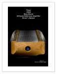
0
Tenor
Line 1/Power1
Ultimate Reference
Dual Chassis/Dual Mono
Preamplifier
Owner’s Manual
Tenor Inc.
Version: July 11,2012
ii
Important Safety Instructions
1. Please read this Owner’s Manual for your own safety and the protection of your Tenor
equipment.
2. Once you have installed your Tenor equipment, store this Owner’s Manual in the travel
case or another safe place for future reference.
3. Please heed all warnings and cautions.
4. Please follow all instructions.
5. Do not use this equipment near water or where there might be a chance it could come in
contact with water.
6. Clean only with a clean dry cloth. See notes under “Care and Maintenance”.
7. Do not install near a heat source such as radiators, heat registers, stoves or any other
source of heat.
8. Do not defeat the safety purpose of the polarized and/or grounding type plug. A polarized plug has two blades with one slightly wider than the other. A grounding plug includes the third ground prong. In the event the plug provided does not fit your power
outlet, consult an electrician for assistance. Failure to do this may result in damage to
the equipment and/or possible injury or death.
9. Please protect the power cord from being walked on or pinched, particularly at the wall
and at the plug on the rear panel of the equipment.
10. The use of extension cords and/or convenience plugs is not advised due to the power requirements of the equipment.
11. Please mount equipment as specified in User Manual.
12. Please unplug equipment during lightning storms. When not in use for long periods of
time unplug the equipment and have a technician remove the rechargeable battery located inside the Line 1 chassis. The battery must be installed and sufficient time with
Power 1 plugged in to AC to charge the battery before system can be used again.
13. Refer all service of equipment to qualified Tenor personnel. In the event the equipment
has been damaged, dropped, exposed to water or foreign objects have entered the
cabinet, disconnect immediately from power source and consult a qualified service technician.
WARNING:
TO REDUCE THE RISK OF FIRE OR ELECTRIC SHOCK, DO NOT EXPOSE THIS
APPLIANCE TO RAIN OR MOISTURE
CAUTION:
TO REDUCE THE RISK OF ELECTRICAL SHOCK, DO NOT REMOVE COVER. NO
USER-SERVICEABLE PARTS INSIDE. REFER ALL SERVICING TO QUALIFIED
PERSONNEL
iii
Table of Contents
Introduction......................................................................................................... 1
Congratulations ........................................................................................................................................1
Safe Set-up Instructions ....................................................................................................................1
Design Principles .....................................................................................................................................1
Precision Crafted, Assembly and Delivery ..............................................................................1
Unpacking ............................................................................................................ 2
Lifting Caution – Line 1 (86lbs/39Kg) & Power 1 (116lbs/53Kg)!............................... 2
Travel Case Opening ............................................................................................................................ 2
List of Items Included with Tenor line 1/Power 1........................................................... 2
Moving Preamplifiers............................................................................................................................ 2
Installation........................................................................................................... 3
Considerations ..........................................................................................................................................3
3rd Party Isolation Stands ...................................................................................................................3
Placement....................................................................................................................................................3
Ventilation...................................................................................................................................................3
Input Source Components...............................................................................................................4
Amplifiers & Speakers..........................................................................................................................4
Remote Turn On Jack ........................................................................................................................4
Power Requirements .......................................................................................... 5
AC Mains Voltage.....................................................................................................................................5
Stabilizing .....................................................................................................................................................5
Mute Operation.......................................................................................................................................5
Break-in Period ....................................................................................................................................... 6
Tube Life ..................................................................................................................................................... 6
Line 1/Power 1 Design Features ....................................................................... 7
Line 1 Design Features ........................................................................................................................7
Power 1 Design Features ...................................................................................................................8
iv
Line 1 Front & Rear Panel................................................................................................................ 9
Power 1 Front & Rear Panel........................................................................................................... 9
Power-up Line 1/Power 1 .............................................................................................................. 10
Initial Power-up Screens..................................................................................................................11
Line 1 Control Knobs/Buttons .................................................................................................... 12
Input Selector ........................................................................................................................................13
Line 1/Power 1 Programming Operation ........................................................ 14
“SETUP” Programming.......................................................................................................................14
STEREO/MONO .......................................................................................................................................15
INPUTS..........................................................................................................................................................15
INPUT Labels ............................................................................................................................................15
OUTPUTS ...................................................................................................................................................16
TAPE 2 ......................................................................................................................................................... 17
GAIN FACTOR .......................................................................................................................................... 17
LINE BAL L ................................................................................................................................................. 18
LINE BAL R................................................................................................................................................. 18
AUDIO GND L ........................................................................................................................................... 18
AUDIO GND R........................................................................................................................................... 19
REMOTE ......................................................................................................................................................19
VFD SAVER.................................................................................................................................................19
VFD POWER...............................................................................................................................................20
VFD TIMER .................................................................................................................................................20
On VOLUME .............................................................................................................................................20
MAX VOLUME .......................................................................................................................................... 21
AUTO OFF .................................................................................................................................................21
CLOCK..........................................................................................................................................................21
FACTORY SET ..........................................................................................................................................22
Line 1/Power 1 Rear Panel .............................................................................. 23
Line 1 Warnings/Cautions...............................................................................................................23
Power 1 Warnings/Cautions/Fuses/Triggers......................................................................23
REMOTE 1 Remote Control.............................................................................. 24
Line 1/Power 1 Remote Control............................................................................................... 24
Troubleshooting Overview ............................................................................... 25
Power 1 – No Power...........................................................................................................................25
v
Line 1 – No Power................................................................................................................................25
Ground Hum............................................................................................................................................25
Care and Maintenance ..................................................................................... 26
Wood Faceplate and Top Rails....................................................................................................26
Metal Chassis and Top Plate.........................................................................................................26
Electrical Connections on Rear Plate....................................................................................26
Audio Board (Vacuum Tubes).......................................................................................................26
Tenor Line 1/Power 1 Specifications.............................................................. 27
Warranty ............................................................................................................ 28
Product Registration ........................................................................................ 29
Tenor Contact Information ............................................................................... 30
Owner’s Notes ................................................................................................... 31
1
Introduction
Congratulations
Congratulations on the purchase of your new Tenor Line 1/Power 1 dual mono dualchassis Ultimate Reference Preamplifier. We are very proud of the extensive engineering, design and craftsmanship in our equipment and are confident that our Line
1/Power 1 preamplifier will deliver the musical experience of your lifetime.
Safe Set-up Instructions
This Owner’s Manual is provided to assist in the unpacking, installation and ongoing
care of your Line 1/Power 1 preamplifier. It is recommended that you take a few
minutes to acquaint yourself with the contents of this manual before unpacking.
Design Principles
The passion and desire to attain the most realistic and live musical reproduction of
recorded material is a lifetime goal of Tenor. Building on our classics, the internationally acclaimed Tenor OTL (Output Transformer-Less), the Tenor 150/300 Hybrid amplifiers, as well as our Ultimate Reference Amplifiers the175S and 350M, the Line
1/Power 1 preamplifier delivers musicality and transparency beyond all other preamplifiers.
Tenor’s proprietary research in the field of Harmonic Structural Integrity (HSI) is the
essence behind each of Tenor’s product line. The Line 1/Power 1 is finest dual chassis/dual mono preamplifier in the world and is designed to be the perfect match for
any of Tenor’s Ultimate Reference Amplifiers.
Precision Crafted, Assembly and Delivery
Each Tenor preamplifier is precision crafted in our facility in Montreal, Canada, by
master technicians dedicated to exacting standards and using the finest of materials.
Rigorous testing, matching and selection of electronic components precedes each
custom build, following which, hundreds of hours of “burn in” ensures complete equilibrium prior to calibration and delivery. Each Line 1/Power 1 is outfitted with a custom travel case which is specially designed to protect the units during transit. Great
care goes into every step to ensure that the Tenor experience for the new owner is
magnificent!
2
Unpacking
Each Line 1/Power 1 is outfitted with a custom travel case which is specially designed
to protect the units during transit. Given the weight and size of the preamplifiers, it
is suggested that careful attention be given to the following:
Lifting Caution – Line 1 (86lbs/39Kg) & Power 1 (116lbs/53Kg)!
The preamplifiers and carrying case have a combined weight of 202lbs (92kg). The
Line 1 with carrying case is 86lbs/39kg. The Power 1 with carrying case is
116lbs/53Kg.
Travel Case Opening
The travel cases have been custom designed to provide the ultimate protection during transit and storage of the preamplifiers. An empty case weighs approximately
50lbs/23Kg. When not in use they should be stored away in a safe and dry location.
The weight of the Tenor Line 1 and Power 1 is not evenly distributed about the centre
axis from front to back which creates a very awkward load, therefore careful attention is required!
Caution should be used in lifting the preamplifier out of the lower portion of the travel
case to make sure that nothing scratches the beautiful Tenor finish. Position the
travel case close to the final location by rolling on the travel case wheels. Clear the
space of the final location in advance and have two reasonably strong people lift the
preamplifier upwards out of the travel case until the preamplifier is clear of the travel
case sides. Special care is needed when installing in a shelving unit due to restrictive
access. When sliding the Tenor Line 1 and Power 1 on a shelf, do not drag on rubber
feet but lift enough weight so that rubber feet do not bind when sliding.
List of Items Included with Tenor line 1/Power 1
•
•
•
•
•
1 Owners Manual
2 Line 1 Umbilical Power Cords to link Line 1 with Power 1
1 Premium Kubala-Sosna Emotion Power Cord for Power 1 AC Mains (N.A. only)
1 Solid Cherry Wood Tenor Remote Control for Line 1
Package of User Accessible Fuses
Moving Preamplifiers
Turn power on on back of Power 1 and let sit for 10 minutes to dissipate high voltages. Disconnect all cables and power cords then disconnect both ends of the special
umbilical power cords between Tenor Line 1/Power 1 then set underneath preamplifier in travel case with ends wrapped in a protective material.
Consult Owner’s Manual for reconnecting cables and power cords following a move.
To protect the beautiful metal and woodwork, it is always recommended to use the
travel case when moving the Tenor Line 1/Power1. The weight of the Tenor Line
1/Power1 is not distributed evenly about the centre axis making for a dangerous
load. It is recommended to always use two people to move.
3
Installation
Considerations
The Tenor Line 1/Power1 needs to be located in a clean, safe and dry environment
within close proximity for the power cord to connect to the AC power mains and close
enough for the interconnects to connect to your amplifier(s) and the custom umbilical
cords to connect the Tenor Line 1/Power 1. Placement on a ventilated open shelf
built for audio equipment is ideal. Only the Tenor Power 1 requires AC.
3rd Party Isolation Stands
Mechanical isolation of the main Tenor Line 1 audio board is achieved with a custom
made suspension. Both the Tenor Line 1 and Power 1 use custom rubber feet to isolate the chassis from acoustic vibrations transmitted through shelves. Although not
necessary, 3 rd party isolation stands can be used but ensure that the units support a
36lbs/16kg and 66lbs/30kg weight for the Tenor Line 1 and Power 1 respectively.
Please note that the weight is not evenly distributed about the centre axis from front
to back of the Tenor Line 1/Power 1.
Placement
AC power mains should be within reasonable access of the Tenor Power 1. The Tenor
Line 1 has two special umbilical power cords that attach to the Tenor Power 1 - which
supplies all of the Line 1 power requirements. The Tenor Power 1 can be ideally installed on an isolated 15 amp circuit @ 1xx Volts (8 Amps @ 2xx Volts) with other
source equipment. Sharing common AC power mains for source equipment is recommended as that generally simplifies any potential for ground loops that cause undesirable 50/60hz ground loop hum. Special grounding options exist in the Tenor Line 1 to
mitigate ground loop hum in the event that this poses a problem.
Ventilation
Ventilation of the Tenor preamplifiers occurs by natural convection without the need
for electric cooling fans. Ventilation slots in the bottom of the chassis and top cover
plate allow sufficient cooling under normal operating conditions. It is imperative that
these vents be kept clean and unobstructed. Please note, the Tenor Line 1 and
Tenor Po wer 1 should never be stacked on top of each other as each preamplifier should have their own shelf with ample ventilation to operate properly.
It is normal for the top cover panel to get warm especially over the tube audio board
located towards the front of the chassis in the Line 1. It is necessary to keep this
top cover installed at all times for safety from high voltages. Keep top cover clear at
all times to ensure maximum ventilation to allow the proper cooling of internal components including the vacuum tubes. The preamplifier sides act as a natural heat sink
which provides cooling for the output devices. The heat sinks run reasonably cool as
long as they are kept clean and unobstructed. Do not operate the Line 1 or Power 1
in bottom half of their travel cases as this will overheat the unit and void the warranty!
4
Input Source Components
The reference quality of the Tenor Line 1/Power1 preamplifier requires your source
components to be of similar reference quality to achieve maximum fidelity. Any imperfections in the audio signal at the input source will most definitely be noticeable.
Alternatively, the best source equipment will allow the Tenor Line 1/Power 1 to reproduce sound so real that you will believe that you are really at the concert!
In practice, Tenor preamplifiers allow most source components to sound their very
best, however, the ultimate in sound reproduction is only achieved with the use of
the finest digital and/or analogue audio source equipment and cables. Either unbalanced or balanced inputs can be used. The use of sufficiently long interconnect cables
allow convenient location of the source equipment away from the amplifiers/speakers
and in close proximity to the user for easy access. To achieve maximum fidelity, it is
our recommendation that reference quality balanced cables be used however unbalanced cables up to 50ft/15m can be used as well. If the installation has excessive RF
and EM pollution you should always consider balanced cables regardless of length.
Over 50ft/15m, balanced cables are mandatory.
Generally all source equipment can be powered using a single AC mains circuit thereby
minimizing the possibility of ground loop hum. It is recommended that this be a separate circuit from the amplifier(s) but have similar overall grounding topology. In cases
where the grounding is not identical and ground loop hum exists, various grounding
options in the Line 1/Power 1 Programming Setup can mitigate this problem. For severe cases, a balanced interconnect between the amplifier(s) and source equipment
will separate the metallic grounds of the two different circuits and minimize any
ground loop hum issues not resolvable by the Tenor programmable grounding options.
Amplifiers & Speakers
The Tenor Line 1/Power 1 is capable of driving virtually any amplifier with 50 feet
(15m) unbalanced or balanced interconnects at lengths up to 200 feet (61 m) with unchanged distortion and noise characteristics. The reproduction of the recorded musical event requires substantial current so we recommend the use of either a Tenor
175S stereo or 350M mono block amplifiers with reference quality speakers. Other
manufacturers’ reference quality amplifiers will also integrate with the Tenor Line
1/Power 1 and benefit from the Tenor Ultimate Reference Preamplifier!
Remote Turn On Jack
The Tenor Line 1/Power 1 provides continuous 12 volts DC via any one of six “Remote
Turn On Jacks” on the back panel when the Line 1 is powered “on”. 3.5 mm stereo
mini phone plugs and communication cable between the Line 1 and Tenor 175S/350M
amplifier(s) (or similarly equipped amplifiers) allows the Tenor Line 1/Power 1 to turn
on each amplifier automatically (in sequence 6,5,4,3,2,1) when the Tenor Line 1 is
powered on. Similarly, turning off the Line 1 will turn off all the amplifiers automatically. Please be mindful of the volume level of the preamplifier when it comes “on line”
after the standard warm-up time of 1 minute 45 seconds. Failure to do so could cause
amplifier and/or speaker failure which would not be covered by the Tenor Warranty.
5
Power Requirements
AC Mains Voltage
Tenor preamplifiers can be powered using conventional Power Company voltages ranging from 100 Volts to 250 Volts at either 50 or 60 Hz. The voltage for your installation
must be specified at the time of ordering so the transformer can be configured to the
correct AC mains cable for your Line 1/Power 1 installation.
The use of power conditioners on the AC power mains feeding the Tenor Line 1/Power
1 combination is not normally necessary since the Power 1 is a complex power supply
optimized to meet the needs of the Line 1 in regard to voltage, current and noise. If
a power conditioner is being used it is recommended that it not be shared with the
power amplifier(s) as the current requirements of most amplifiers will negatively affect the current available to the Line 1/Power 1 and thereby diminish the available
power being supplied and, as a result, diminish the overall signal.
Appropriate regional electrical codes and professionals should be consulted regarding
any custom electrical configuration beyond the regular domestic wiring of your installation. Damage caused to the Tenor Line 1/Power 1 as a result of incorrect wiring is
not covered by Warranty.
Stabilizing
The master AC Mains Power switch of your Tenor Line 1/Power 1 is located at the
centre rear back plate of the Power 1 chassis. This switch powers the Tenor Line
1/Power 1 so the right push button control knob on the Line 1 front panel can be used
to turn the preamplifier on as well as off. With the AC Mains Power in the “on” position, a push of the right control knob “in” for 3 seconds will begin a controlled start of
the Tenor Line 1/Power 1. The Vacuum Florescent Display (VFD) on the front panel
will show “STABILIZING” for 1 minute 45 seconds during which no other control knob
or button should be pushed. Once 1 minute 45 seconds has expired the VFD will then
show the preset volume level signifying the Line 1/Power 1 is now on line and ready
for use. The Tenor 175s/350M amplifiers will come on line at just over 2 minutes.
Please Note: It is advisable for the protection of your amplifiers/speakers that the
Tenor Line 1/Power 1’s “ON VOLUME” be set to 0 (zero) until amplifiers are on line.
Mute Operation
Mute operation is achieved by pushing the right control knob “in” when the Tenor
Line 1/Power 1 is powered up (or pushing the remote control’s mute button).
Mute is not a “standby” in the traditional instrument or PA preamplifier sense as the
Tenor Line 1/Power 1 is still fully powered but simply muted. It is not advisable to
leave the amplifier in “mute” when not in use as the tube life will be diminished considerably. The preamplifier is designed to provide near full potential immediately following the 1 minute 45 seconds warm-up and stabilization period. Maximum dynamic
headroom and transparency is achieved following about 60 minutes of continued
operation when thermal equilibrium is achieved.
6
Break-in Period
Various components of the Tenor Line 1/Power 1 are “burned-in” for a period up to
200 hours prior to assembly. Following assembly, each preamplifier is further
“burned-in” at the Tenor factory for a period of no less than 100 hours thereby allowing each electronic component to stabilize and achieve its optimum electrical and musical equilibirum as a system. Each preamplifier is then calibrated to the factory
specification and is designed to remain within tolerance for a period up to 10 years or
more depending on use and care.
Tube Life
The Tenor Line 1/Power 1 is designed to operate within design specifications for a
period close to 10,000 hours. As a typical example, a Tenor Line1/Power 1 used each
and every day for 3 hours under normal use will last almost 10 years before it will need
a tube refit and calibration. Each time one turns the Line 1 on an “elapsed hours
clock” is located on the Vacuum Florescent Display (VFD), as shown below, which exhibits the owner’s hours of enjoyment to date. Most owners will experience a lifetime
of listening pleasure without ever reaching the 10,000-hour maximum. When the
10,000 hours of use has been achieved, the preamplifier should be returned to the
factory for re-tubing and calibration.
ELAPSED TIME
7
Line 1/Power 1 Design Features
Line 1 Design Features
1. Combination custom extruded/machined aluminum chassis providing a stable,
rigid base for electronics plus solid cherry wood face plate and rails accents
2. Microprocessor controlled Vacuum Florescent Display (VFD)
3. Hand held solid cherry wood remote control
4. Internal USB software upgrade port (requires technical support)
5. High quality polytetrafluroethylene (PTFE) insulation and rhodium plated unbalanced connectors for maximum reliability and low Elector-magnetic Interference (EMI)
6. High quality pro-audio grade gold plated balanced connectors for maximum reliability and low Electro Magnetic Interference (EMI)
7. 5 unbalanced line level inputs
8. 2 balanced line level inputs
9. 2 unbalanced in/out tape or processor loops
10. 2 unbalanced selectable outputs
11. 2 balanced selectable outputs
12. 1 headphone output
13. Transformer balanced inputs/outputs for high Common Mode Rejection
Ratio (CMRR) for low noise operation with pin 1 ground lift to suppress interchassis ground loops
14. Individual ground path for left/right channels to increase immunity to ground
loops and inter-channel crosstalk
15. 3 position ground selector per channel to equalize ground potentials and minimize system residual noise
16. Input/output audio signal switched concurrently to avoid audio ground mixing/noise summing thereby maximizing signal to noise performance
17. Audio amplification circuit employs 4 New Old Stock (NOS) 10,000 hour 6463
high grade select vacuum tubes per channel in pure class A, zero negative
feedback delivering ultra-low distortion thereby maintaining the natural structure of the audio signal
8
18. Custom precision control assemblies with optical encoder interfaces provide
custom “eVolume” and “eControl” of Line 1/Power 1 as well as logic controlled
Tenor remote control.
19. High current pure class A ultra-low distortion unity gain solid state buffer
stages provide isolation from vacuum tube circuit using discrete transistors
rather than ICs for maximum sonic performance
20. Low output impedance can drive hundreds of feet of interconnect with unchanged distortion and noise characteristics
21. High bandwidth double shielded balancing custom made transformers with ultra-low distortion for balanced inputs/outputs
Power 1 Design Features
1. Combination custom extruded/machined aluminum chassis providing a stable,
rigid base for electronics plus solid cherry wood face plate and rails accents
2. Medical grade low leakage AC inlet module with integrated EMI filter
3. Dual mono power supply with independent transformers and ground path for
left/right channels
4. Oversized custom made ultra-low noise, low-stray magnetic field, dual electrostatic shield power transformers potted in special epoxy resin for noise reduction
5. In-rush current limiters used in conjunction with slow start circuitry to optimize long term reliability of vacuum tubes and electronic components
6. Silver plated copper wires with 600V PTFE insulation used extensively with high
quality crimped connectors for long term stability
7. DC supplies individually choke filtered and independently regulated for each
channel with oversize low noise DC supplies for amplification stages
8. 6 output 12 volt DC triggers provided to remotely power up to 6 power amplifiers in sequential start up mode starting at 6,5,4,3,2,1
9. Front panel LEDs indicate Tenor Power 1 operating status
10. High quality DC interconnects with military grade aluminum connectors provides safe secure power and long term stability
11. Relatively low operating temperature and premium quality printed circuit
boards ensure long term reliability and fidelity
12. Power supplies are custom made, hand assembled and intensively tested
9
Line 1 Front & Rear Panel
Power 1 Front & Rear Panel
The front panel of the Tenor Line 1/Power 1 preamplifier is made from the finest selected cherry wood and has been hand finished with 16 coats of clear piano lacquer by
local Canadian Artisans.
Over time the cherry wood will age by showing a somewhat mellow patina making the
preamplifier even more beautiful. The same is also true of the decorative cherry rails
on the top of each chassis and the custom solid cherry wood remote control. Please
Note: Direct sunlight will cause an overall darkening of the cherry wood. This is normal so if this effect is not desired then protection from direct sunlight is required.
Natural aging of the cherry wood is normal and expected so any patina due to this is
not covered under warranty.
The metalwork of the Tenor Line 1/Power1 preamplifier is anodized aluminum that has
been precision manufactured and finished by local Canadian artisans.
Please review section “Care and Maintenance” of this manual for further details.
10
Power-up Line 1/Power 1
There are two power switches on the Tenor Line 1/Power1 preamplifier – the main
“LINE POWER ON/OFF” on the back of the Power 1 and the right control knob on the
Line 1.
First, connect the two power umbilical cords that provide power to the Line 1 chassis
from the Power 1. These are custom cables to provide various voltages from the
Power 1 power supply to the Line 1.
Please note that the left side connector of the Power 1 should only connect to the left
side connector of the Line 1 and vice versa for the right side. This is critical as they
are not identical to each other and failing to do so could cause damage to the Line 1
or Power 1 that would not be covered by warranty.
Once the two umbilical cords are securely attached, it is now time to connect the
source inputs and the preamplifier outputs to the amplifier(s). Following this, you can
then attach the power cord to connect the Power 1 to the AC mains. This would be
an appropriate time to double-check all of your connections before the AC mains
power is applied.
Once your connections have been verified, you can now turn on the Power 1 using
the “ON/OFF” master power switch. The following picture is provided for identification on the back of the Tenor Power 1:
Turning the LINE POWER ON/OFF switch to “ON” provides power to the Power 1 that
in turn provides power to the Line 1 through the dual umbilical cords. The final step to
power-up the Line 1 is by pushing the right control knob “in” which will initiate the
power-up sequence.
Please Note: Hazardous voltages inside the Tenor Line 1/Power 1 are dangerous!
Please allow 10 minutes for high voltage to dissipate before allowing anyone to open
either Tenor Line 1 or Power 1 chassis.
11
Initial Power-up Screens
Turn the Power 1 “LINE POWER” button on back of chassis to “ON”. Pressing any
knob or button on the Line 1 will then immediately wake and show screen A below providing simple instructions for power-up. Holding right control knob in for 3 seconds
will begin a sequence of events displayed on the Vacuum Florescent Display (VFD)
starting with the screen B as follows:
A
E
B
F
C
G
D*
*
(Volume Control Calibration will be performed after a power failure or on the
first power up after a battery replacement in the Tenor Line 1)
The factory setup is now loaded whereby the default setup is:
•
•
•
•
INPUT:
OUTPUT:
BAL:
STEREO:
LINE 1
OUT 1
0db
STEREO
To power-down the Line 1, simply hold the right control knob for 3 seconds until shutdown sequence begins. Leave the Power 1 “Line Power” button “ON” unless storing,
moving or leaving unattended for long periods of time.
12
Line 1 Control Knobs/Buttons
The control of the Line 1 is simple and straightforward:
1. Touch any knob or button gives power on/off instructions
2. Push the right control knob in for 3 seconds to turn the Line 1 “on” or “off”
3. Avoid touching any control knobs/buttons during the “on” stabilizing & initialization period or during the “off” shutdown sequence
4. VOLUME level is right control knob (rotate +or- for level)
5. INPUT is left control knob (confirm selection by pushing “in”)
6. MUTE the volume output by briefly pushing “in” the right control knob
7. UN-MUTE the volume output by pushing the right control knob “in” again
8. BALANCE left/right channels by selecting “BALANCE” button then turning
left control knob – selection is automatically saved
9. Selecting the “SETUP” button then rotating the left control knob clockwise
for programming selection (see Line 1/Power 1 Programming Operation)
10. Selecting the “INFO” button then rotating the left control knob clo ck wise
allows the factory settings to be reviewed
11. Pushing “DISPLAY” button cycles between “MAIN”, “LOGO” and “BLANK
screensavers (allow a few seconds to change after selecting) which will revert
to no screen saver if not already turned on in “SETUP”. If screen saver is already turned on in “SETUP” then the last screensaver will be saved in “SETUP”
13
Input Selector
Rotating the left control knob moves between the following screens which represent
the various input selection:
Pushing the left control knob “in” will enter your selection and save it in memory.
The following picture shows the unbalanced and balanced inputs:
14
Line 1/Power 1 Programming Operation
“SETUP” Programming
Entering the programming mode of the Line 1 is achieved by pushing the “SETUP” button. The Vacuum Florescent Display (VFD) then displays the following screen:
Rotating the left control knob clockwise provides these setup options:
STEREO/MONO
REMOTE (Cont rol)
INPUTS
VFD SAVER (Display Save r)
OUTPUTS
VFD POWER (Display Powe r)
TAPE 2
VFD TIMER (Display Time r)
GAIN FACTOR
LINE BAL L (L PIN 1 GND o r Lift)
LINE BAL R (R PIN 1 GND o r Lift)
AUDIO GND L (Audio G round Left)
AUDIO GND R (Audio G round Right)
ON VOLUME
MAX VOLUME
AUTO OFF
CLOCK
FACTORY SET
15
STEREO/MONO
The STEREO/MONO setup has 2 choices available by rotating the left control knob and
pushing in to select:
INPUTS
The INPUT setup has 10 choices available by rotating the left control knob clockwise
and pushing in to select:
INPUT Labels
Inputs can be labeled by selecting the “INPUT” from selection above then choosing a
label from the following table:
DEFAULT
D/A 1
IPOD
PHONO 2
SAT 1
TUNER 1
OFF
D/A 2
ITUNES
RADIO
SAT 2
TUNER 2
CD
DVD
LASER
R2R
SERVER
TV
CD 1
DVD 1
MP3
R2R 1
SERVER 1
TV 1
CD 2
DVD 2
PHONO
R2R 2
SERVER 2
TV 2
D/A
IPHONE
PHONO 1
SAT
TUNER
VCR
Note: Selecting “DEFAULT” labels INPUT as factory setting and “OFF” removes INPUT
from use. (If all INPUTS are turned “OFF” then “NO INPUT” shows on main screen)
16
OUTPUTS
By further rotating the left control knob clockwise (after selecting “SETUP”) takes
you to the OUTPUT selection:
Out 1 = Output 1 Unbalanced
Out 2 = Output 2 Unbalanced
Out 1&2 = Output 1&2 Unbalanced
Out 2(BAL) = Output 2 Balanced
Out 1&2(BAL) = Output 1&2 Balanced
Only Phones = Headphones Output Only
(Picture of Outputs from Line1 back)
Out 1(BAL) = Output 1 Balanced
17
TAPE 2
Rotating the left control clockwise and selecting “TAPE 2” gives either “VARIABLE”
(normal Tenor volume control) or “DIRECT” (bypasess the volume control at a customer preset volume level). This can also be used in a configuration with an A/V preamplifier where the Tenor system is used for audio but the volume control of the A/V
preamplifier is required for controlling the volume when watching video content.
Please Note: The Tenor Line 1 will power up in “MUTE” if left on “TAPE 2” when last
powered down. This protects the system from dangerous volume levels from the A/V
preamplifier. Always minimize volume on A/V preamplifier while turning on Tenor to
protect against high input level which could cause serious damage to all equipment!
VARIABLE
DIRECT Selection (1-38)
GAIN FACTOR
Rotating the left control clockwise and selecting “GAIN FACTOR” gives either “NORMAL” gain or “HIGH” gain (additional 6db) depending on your preference and equipment:
NORMAL
HIGH
18
LINE BAL L
Rotating the left control knob clockwise and selecting “LINE BAL L” gives ability to lift
PIN 1 or leave grounded on the left balanced input (Note: It is not necessary that
LINE BAL L and LINE BAL R be set the same when resolving hum from ground loops):
GROUNDED
PIN 1 LIFTED
LINE BAL R
Rotating the left control knob clockwise and selecting “LINE BAL R” gives ability to lift
PIN 1 or leave grounded on the right balanced input (Note: It is not necessary that
LINE BAL L and LINE BAL R be set the same when resolving hum from ground loops):
GROUNDED
PIN 1 LIFTED
AUDIO GND L
Rotating the left control knob clockwise and selecting “AUDIO GND L” gives the
choice of NORMAL (resistor) grounding, GROUNDED (no resistor) and LIFTED (no
ground) for the left channel (Note: It is not necessary that AUDIO GND L and AUDIO
GND R to be set the same when resolving hum from ground loops):
NORMAL
GROUNDED
LIFTED
19
AUDIO GND R
Rotating the left control knob clockwise and selecting “AUDIO GND R” gives the
choice of NORMAL (resistor) grounding, GROUNDED (no resistor) and LIFTED (no
ground) for the right channel (Note: It is not necessary that AUDIO GND L and AUDIO
GND R to be set the same when resolving hum from ground loops):
NORMAL
GROUNDED
LIFTED
REMOTE
Rotating the left control knob clockwise and selecting “REMOTE” gives the choice of
Infra Red (IR) codes available for the remote control. Generally, the only time the
factory default would not be used is when there is a conflict with another IR code.
Please consult with the factory to discuss further before making any changes.
REMOTE
VFD SAVER
Rotating the left control knob clockwise and selecting “VFD SAVER” gives the choice
of “LOGO” (Tenor), “MAIN” (input, output, volume level, balance, stereo) and simply
“BLANK”. Purists may choose “BLANK” as digital VFD is turned off after no interaction of Tenor Line 1.
VFD SAVER (Display Saver)
Selections
20
VFD POWER
Rotating the left control knob clockwise and selecting “VFD POWER” gives the choice
of “HIGH”, “MEDIUM” or “LOW” brightness settings for the Vacuum Florescent Display (VFD). Each selection has a higher initial brightness and a lesser runtime brightness for the screen saver).
VFD POWER (Display Power)
Selections
VFD TIMER
Rotating the left control knob clockwise and selecting “VFD TIMER” gives the timers
that must expire before the screen saver set under “VFD SAVER” begins on the Vacuum Florescent Display (VFD).
VFD TIMER (Display Timer)
Selections
On VOLUME
Rotating the left control knob clockwise and selecting “ON VOLUME” selects the volume level that will be selected automatically when the Line 1 is powered on. The minimum setting of “00” on power up is ideal as you can easily select a comfortable listening level without worry of damaging your other equipment.
ON VOLUME
Selections (0 – 16)
21
MAX VOLUME
Rotating the left control knob clockwise and selecting “MAX VOLUME” selects the
maximum volume level that can be used. A maximum level of “80” or full volume is selectable but anything over “30” is not recommended as damage to other equipment
could occur if volume is turned up to high.
MAX VOLUME
Selections (0-85)
AUTO OFF
Rotating the left control knob clockwise and selecting “AUTO OFF” allows the time to
be set for the system to turn itself off as well as any amplifiers using triggers attached to Line 1. This feature safeguards against forgetting to turn the system off.
The timer begins each time you interface with the Line 1 so the timer begins counting
only after the last time you used the Line 1. For example, volume up was the last
change you made which starts timer based on your “AUTO OFF” selection.
AUTO OFF
Selections
CLOCK
Rotating the left control knob clockwise and selecting “CLOCK” allows you to set the
proper time in order of YEAR, MONTH, DAY, HOUR, MINUTE, SECOND (Note: Once you
start this sequence you must finish):
CLOCK
22
FACTORY SET
Rotating the left control knob clockwise and selecting “FACTORY SET” allows you to
load the original factory settings (NOTE: This will reset any custom programming you
have made requiring you to reprogram your custom settings again).
FACTORY SET
You can review the factory setup by simply pushing the “INFO” button under the
Vacuum Florescent Display (VFD) then scrolling through with the left control knob to
display each setting as follows:
Date of Manufacture
Main Operation Voltage
Elapsed Time
Serial Number
AC Main Fuse Rating
Current Time & Date
Firmware Version
HV Main Fuse Rating
Unit Owner
Last Firmware Update
Last Time Used
23
Line 1/Power 1 Rear Panel
Line 1 Warnings/Cautions
Power 1 Warnings/Cautions/Fuses/Triggers
24
REMOTE 1 Remote Control
Line 1/Power 1 Remote Control
The REMOTE 1 is a truly unique preamplifier remote control made out a single piece of
solid cherry wood finished by local artisans with 16 coats of piano lacquer to look exactly like the front plates of the beautiful Line 1/Power 1 it controls.
Functionality includes:
1. Stepped Volume - up or down
2. Mute/UnMute Volume at the push of a button
3. Step through Input Sources - in either direction
4. Direct Select of 7 Input Sources
5. Cycle through VFD Display Screensavers
6. On/Off of Line 1 with the push of single button
25
Troubleshooting Overview
Power 1 – No Power
Generally when the Power 1 is plugged into AC Mains and the power switch is “on” you
will see status lights in the front lens as follows:
When operating normally you should see “POWER ON”, “HV Left”, “HV Right” and
“TRIGGER ON” lit up. Three fuses accessible from the back of the Power 1 should be inspected and replaced only with fuse specified for voltage of unit. The “Standby” fuse of
200ma Slow Blow inside the Power 1 is accessible only to a technician.
Line 1 – No Power
First ensure that the power umbilical cords are connected to the Power 1. Take note
that the Line 1 left side must be connected to the left side Power 1 and vice versa.
Verify that the Power 1 main ‘on/off” switch is on and that the “POWER ON” light is
on. Then push the right control knob of the Line 1 in to initiate start up sequence.
Two dc fuses of 100ma Fast Blow are located inside the Line 1 and are accessible only to
a technician should the Power 1 be powered and the Line 1 is not.
Ground Hum
Ground hum is a common problem when multiple AC mains sources are used. Ideally, all of
the source equipment should be plugged into the same circuit so they all share the same
grounding characteristics thereby negating your possibility for ground loops and the
associated annoying 50hz/60hz hum. If the source equipment does not share all of the
same ground, you could end up with ground loop noise. If you do, please rearrange your
AC mains, if possible, to be on a single circuit.
Amplifiers typically have their own grounding which is often different than that of the
source equipment. With mono blocks using separate AC mains supplies in addition to
your source equipment AC mains, it is probable that you will need to use the ground lifts
of the Line 1/Power1 as well as the ground lifts of your amplifiers.
The Tenor Line 1/Power1 has grounding options to remedy a ground loop problem on either balanced or unbalanced connections and are selectable for left, right or both
channels. Tenor amplifiers also have sophisticated grounding options available, which
can be used to help solve a ground hum problem. Please consult the Line 1/Power 1 Programming Operation of this user manual as well as your amplifier manual to resolve any
ground hum problems. Do not be concerned about having lifts the same.
26
Care and Maintenance
Wood Faceplate and Top Rails
The hand lacquered Wood Faceplate and Top Rails of the Tenor Line 1/Power1 require
very little maintenance. Should they become marked with fingerprints, a polish used for
fine furniture can be used but only if applied to a soft cloth and then rubbed on the
wood. Spraying polish directly on the wood may contaminate the electrical components
inside and could void the Warranty. Keep out of direct sunlight if at all possible as the
cherry wood will darken substantially.
Metal Chassis and Top Plate
The Metal Chassis and Top Plate need very little care other than dusting from time to
time. Do not use spray wax or dusting liquid as it may contaminate the electrical components inside and could void your Warranty. Dusting with a soft brush is recommended.
Electrical Connections on Rear Plate
From time to time it is good to disconnect and reconnect your cables at the rear to improve any degradation due to normal electrical oxidization. Make sure your amplifier is
turned off when you do this and that you disconnect then reconnect each connecter
one at a time to avoid any mix up.
Audio Board (Vacuum Tubes)
The Audio Board is home to all of the Vacuum Tubes in the Tenor Line 1/Power 1. Every
tube is matched and calibrated in the circuit so unless you are specifically directed by
Tenor to alter these tubes they should never be touched except by trained Tenor service technicians. Each tube has been selected for its optimum electrical characteristics
and the entire circuit has been calibrated for these specific tubes. Any alteration of
the tubes may cause the Tenor Line 1/Power 1 to be out of specification and any failure
as a result would not be covered by Warranty.
27
Tenor Line 1/Power 1 Specifications
Preamplifier Type……………………………………………………….……...….Dual Chassis/Dual Mono
Volume Steps……………………………………………………………….……………......…………………………80
Voltage Gain………………........................……………….………..14db or 20db (selectable)
Rated Input*………….……………….…………….…….………...12V rms Single Ended or Balanced
Rated Output*…………………………………….………….…..….30V rms Single Ended or Balanced
S/N Ratio Reference @ Normal Listening……….....…………..………………………….<-120 dBA
S/N Ratio Reference @ 2V rms Output……..…………..…….………………………………<- 108dBA
S/N Ratio Reference @ Maximum Output*…………….…..………………….……………….<- 94dBA
Channel Separation*…....……………….…..………….…………......….….…….…...………..<-90dBA
Frequency Response 2-100,000 Hz*………….…….….…………....…..….…..... +0dbA -0.5dBA
Frequency Response 2-500,000 Hz*…………....…………..……..………….…...... +0dbA -3dBA
THD + Noise* ….……………………….……………………………….………………………….......…..< 0.06%
IMD*….………………………………………….…………………………………………………….......….….< 0.06%
Input Impedance 20hz-20,000hz.………………...20,000Ω Single Ended / 4500Ω Balanced
Output Impedance*…………………….……………...…….……10Ω Single Ended / 100Ω Balanced
Rise Time*…………………….…………………..……………........…………………………………….…….0.8 µs
Global Negative Feedback…………………….…………......…………………………………….……….Zero
Power 1 HV & LV Ultra-Low Noise/Radiation Transformers (per Channel)......100 VA
Standby Transformer ……………………………………….…………………………………..……...…..10 VA
Balanced Input Pin Configuration…………………..……1: Ground, 2: Positive, 3: Negative
Input Tubes (per Channel)………………………….………….…….……………………..4xNOS GE 6463
Soft Start……………………………………………….………………..……………………1 Minute 45 Seconds
Sequential Remote Turn On………………..………...….6 outputs@12 VDC, Mini-Phone Plug
Cooling…………………………………………….……………...………..………………….Natural Convection
Microphonic Isolation……………….......Suspended Audio Board/Tube Vibration Control
Fuses Line 1 (dc)……………………………………………………………………………...……………...........2
Fuses Power 1…………………………………………………….………...……………...……………………………4
Maximum Power Consumption during Operation……….……..…...………………….185Watts
Maximum Power Consumption during Standby………....…….……………….….…….0.7 Watts
Supply Voltage Factory Set…………………………….....………..…..100 to 250VAC, 50/60 Hz
AC Mains Input (Power 1 Only)……………………......………15A IEC Detachable Power Cord
AC Mains Input (Line 1)……………….…….…………......….Custom Tenor Dual Umbilical Cord
Weight Line 1 …………………………………………….………….……….....…………………….36lbs / 16kg
Weight Power 1…………………………………………………………..….....……………………..66lbs / 30kg
Shipping Weight Line 1……………………..………………………….....……………………….86lbs / 39kg
Shipping Weight Power 1…………………………………………………....…….…………….116lbs / 53kg
Dimensions Line 1....19.5in W x 19.5in D x 9.5in H / 495 mm W x 495mm D x 241mm H
Dimensions Power 1..19.5in W x 19.5in D x 9.5in H / 495 mm W x 495mm D x 241mm H
* : @ 120V AC @ 1kHz & 2V rms input
Tenor Inc. reserves the right to make improvements without notice that may result in specification changes. (July 11, 2012)
28
Warranty
Tenor Inc. Canada warrants the Tenor Line 1/Power 1 to be free from defects in materials or workmanship for a period of 5 years from the date of the original purchase provided the preamplifier is registered with Tenor Inc. Canada within 90 days of the purchase date and there is valid proof of purchase from an authorized Tenor Inc. Canada
dealer or distributor. If the Tenor preamplifier is not registered within 90 days of the
purchase date then the warranty will be limited to only 1 year with a valid proof of purchase from an authorized Tenor Inc. Canada dealer or distributor.
Following the receipt of your registration and upon successful validation that your amplifier has been purchased from an authorized Tenor Inc. Canada dealer or distributor,
you will receive a custom plate for mounting on the back of each amplifier which shows
the amplifier has been purchased from an authorized dealer or distributor and has been
custom made for you. This plate must be affixed to the back of the amplifier for the
warranty to be valid. Any Line 1/Power 1preamplifier returned to Tenor Inc. Canada
without this custom plate affixed will have its Warranty revoked.
Vacuum tubes are guaranteed for 10,000 hours or 5 years from the original purchase
date - whichever comes first. If the warranty has not been registered within 90 days
then the tubes will only be warranted for 1 year regardless of hours of use.
Should the Tenor Line 1/Power 1 be defective during the Warranty period, Tenor Inc.
Canada will elect at its sole discretion to either repair or replace the unit free of
charge.
Prior Authorization and a Return Authorization Number (RAN) are mandatory for Tenor
Inc. Canada to undertake any service under the aforementioned Warranty.
Transportation costs and insurance costs for shipment to/from Tenor Inc.’s Canadian
Service Facility for Warranty repair are the responsibility of the owner.
The use of Vacuum tubes not supplied by Tenor Inc. Canada will void the Warranty.
Attempting to repair or modify Tenor Line 1/Power 1 preamplifier will void the Warranty.
Missing or altered serial numbers automatically void the Warranty.
29
Product Registration
To ensure your amplifier is covered by the Tenor Inc. Canada 5 year warranty, it is
mandatory that you register with Tenor Inc. Canada by mail or email within 90 days of
purchase and provide us with all of the following information:
Model Number: ___________________________________________
Serial Number of each Line 1/Power 1: ________________________________
Date of Purchase: _________________________________________
Dealer and/or Distributor’s Trade Name & Contact Name:
________________________________________________________
Dealer and/or Distributor’s Phone Number: ___________________
Dealer and/or Distributor’s Email Address: ___________________
Dealer and/or Distributor’s Address:
_________________________________________________________
_________________________________________________________
_________________________________________________________
_________________________________________________________
Your Name (will be engraved on custom plate):
_________________________________________________________
Your Phone Number: _______________________________________
Your Email Address: _______________________________________
Your Address:
_________________________________________________________
_________________________________________________________
_________________________________________________________
_________________________________________________________
Failure to provide any of the above information will void your warranty registration.
30
Tenor Contact Information
Before returning your amplifier to Tenor Inc. Canada, it is necessary to receive a Return Authorization Number (RAN) as stated in Warranty Conditions.
A RAN will be issued by contacting Tenor Inc. Canada and describing the nature of your
service request using either email or phone as follows:
Tenor Inc. Canada Service Email: service@tenoraudio.com
Tenor Inc. Canada Service Phone Number: 705 717 1705
Once you have received a RAN, you can ship your preamplifiers to the following address
with the RAN marked clearly on the outside of the shipping cases (Please note that
shipping costs and insurance door to door including customs are the responsibility of
the shipper):
Tenor Inc.
1001 Lenoir, Suite A-209
Montreal, PQ,
Canada, H4C 2Z6
Phone Number is 514 933-6035
Other contact information is as follows:
Web Site is: www.tenoraudio.com
Sales Email: sales@tenoraudio.com
31
Owner’s Notes