1
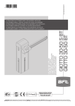
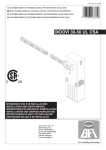
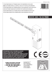
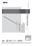
D811480 ver. 07 13-07-12
I AUTOMATISMO ELETTROMECCANICO PER BARRIERA VEICOLARE
GB ELECTROMECHANICAL CONTROL DEVICE FOR VEHICULAR BARRIERS
F AUTOMATISME ELECTROMECANIQUE POUR BARRIERE POUR VÉHICULES
D ELEKTROMECHANISCHER ANTRIEB FÜR FAHRZEUGSCHRANKEN
8
027908
283818
E AUTOMATISMOS ELECTROMECANICOS PARA BARRÉRAS VEHICULAR
P AUTOMATIZAÇÃO ELECTROMECÂNICA PARA BARREIRA VEICULAR
MOOVI 30S / 30-50 RMM
ISTRUZIONI D’USO E DI INSTALLAZIONE
INSTALLATION AND USER’S MANUAL
INSTRUCTIONS D’UTILISATION ET D’INSTALLATION
INSTALLATIONS-UND GEBRAUCHSANLEITUNG
INSTRUCCIONES DE USO Y DE INSTALACION
INSTRUÇÕES DE USO E DE INSTALAÇÃO
Via Lago di Vico, 44
36015 Schio (VI)
Tel.naz. 0445 696511
Tel.int. +39 0445 696533
Fax 0445 696522
Internet: www.bft.it
E-mail: sales@bft.it
D811480_07
2 - MOOVI 30S-30RMM-50RMM
Ver. 06
USER’S MANUAL
Thank you for buying this product. Our company is sure that you will be
more than satisfied with the performance of the product. This product is
supplied with a “WARNINGS” leaflet and an “INSTRUCTION MANUAL”.
These should both be read carefully as they provide important information
about safety, installation, operation and maintenance. This product complies
with recognised technical standards and safety regulations. We declare that
this product is in conformity with the following European Directives: 89/336/
CEE, 73/23/EEC, 98/37/EEC and subsequent amendments.
1) GENERAL OUTLINE
Compact electromechanical barrier suitable for limiting private areas, parkings, access areas for vehicles only. Available for passageways from 3 to 5
metres. Adjustable electromechanical limit devices ensuring a correct stop
position for the boom. In case of intensive use, a thermal sensor activates
the cooling fan.
The emergency release device for manual manoeuvre is controlled by a
personalised key lock.
The actuator is always supplied for left-hand side fitting. However, when necessary, the opening direction can be reversed by means of simple operations.
The CBO mod. foundation base (on request) makes barrier installation easier.
Appropriate fittings make it easy to install accessories without needing to
drill any holes.
is essential to frequently check that all safety devices are perfectly efficient.
WARNING! In case of any malfunction in the safety devices, take immediate
action and require the assistance of a specialised technician.
It is recommended to keep children at a safe distance from the automation
field of action.
4) SCRAPPING
Materials must be disposed of in conformity with the current regulations. In
case of scrapping, the automation devices do not entail any particular risks
or danger. In case of recovered materials, these should be sorted out by
type (electrical components, copper, aluminium, plastic etc.).
The descriptions and illustrations contained in the present manual are
not binding. The Company reserves the right to make any alterations
deemed appropriate for the technical, manufacturing and commercial
improvement of the product, while leaving the essential product features unchanged, at any time and without undertaking to update the
present publication.
WARNING! The barrier must be exclusively used for vehicles to
drive through. Pedestrians must not walk within the operator
manoeuvring area. An appropriate pedestrian passageway must be
provided for.
2) EMERGENCY RELEASE (Fig.1)
The emergency release allows the bar to be manoeuvred manually. It is
activated from the outside of the box by inserting the personalised key into
the lock placed under the bar and rotating it anticlockwise by 180°.
WARNING! When an actuator without bar needs to be released, ensure
that the balancing spring is not compressed (bar in the opening position).
3) USE OF AUTOMATION
As automation can be remotely controlled and therefore not within sight, it
Fig. 1
4 - MOOVI 30S-30RMM-50RMM
Ver. 06
D811480_07
ENGLISH
D811480_07
ENGLISH
INSTALLATION MANUAL
Thank you for buying this product. Our Company is sure that you will be
more than satisfied with the performance of the product. This product is
supplied with a “WARNINGS” leaflet and an “INSTRUCTION MANUAL”.
These should both be read carefully as they provide important information about safety, installation, operation and maintenance. This product
complies with recognised technical standards and safety regulations. We
declare that this product is in conformity with the following European Directives: 89/336/CEE, 73/23/EEC, 98/37/EEC and subsequent amendments.
1) GENERAL OUTLINE
Compact electromechanical barrier suitable for limiting private areas,
parkings, access areas for vehicles only. Available for passageways
from 3 to 5 metres. Adjustable electromechanical limit devices ensuring
a correct stop position for the boom. In case of intensive use, a thermal
sensor activates the cooling fan.
The emergency release device for manual manoeuvre is controlled by a
personalised key lock.
The actuator is always supplied for left-hand side fitting. However, when
necessary, the opening direction can be reversed by means of simple
operations.
The CBO mod. foundation base (on request) makes barrier installation
easier.
Appropriate fittings make it easy to install accessories without needing
to drill any holes.
The LEO-MV-D control panel is supplied by the manufacturer with standard
setting. Any alteration must be set by means of the incorporated display
programmer or by means of Universal palmtop programmer. The Control
unit completely supports the EELINK protocol, including the programmer
self-supply from the control unit.
Its main characteristics are:
- Closing / opening limit-switch inputs
- Separate inputs for safety devices
- Clock input
- Serial protocol connection input
- Incorporated radio receiver
The board is provided with a terminal board which can be pulled out for
easier maintenance or replacement. The board is supplied with a series
of pre-wired jumpers to facilitate the installer’s work.
The jumpers relate to the following terminals: 21-23, 21-24 and 21-30. If the
above-mentioned terminals are in use, remove their respective jumpers.
2) GENERAL SAFETY
WARNING! An incorrect installation or improper use of the product
can cause damage to persons, animals or things.
• The “Warnings” leaflet and “Instruction booklet” supplied with this
product should be read carefully as they provide important information
about safety, installation, use and maintenance.
• Scrap packing materials (plastic, cardboard, polystyrene etc) according
to the provisions set out by current standards. Keep nylon or polystyrene
bags out of children’s reach.
• Keep the instructions together with the technical brochure for future
reference.
• This product was exclusively designed and manufactured for the use
specified in the present documentation. Any other use not specified
in this documentation could damage the product and be dangerous.
• The Company declines all responsibility for any consequences resulting
from improper use of the product, or use which is different from that
expected and specified in the present documentation.
• Do not install the product in explosive atmosphere.
• The construction components of this product must comply with the
following European Directives: 89/336/CEE, 73/23/EEC, 98/37/EEC
and subsequent amendments. As for all non-EEC countries, the abovementioned standards as well as the current national standards should
be respected in order to achieve a good safety level.
• The Company declines all responsibility for any consequences resulting from failure to observe Good Technical Practice when constructing
closing structures (door, gates etc.), as well as from any deformation
which might occur during use.
• The installation must comply with the provisions set out by the following European Directives: 89/336/CEE, 73/23/EEC, 98/37/EEC and
subsequent amendments.
• Disconnect the electrical power supply before carrying out any work
on the installation. Also disconnect any buffer batteries, if fitted.
• Fit an omnipolar or magnetothermal switch on the mains power supply,
having a contact opening distance equal to or greater than 3,5 mm.
• Check that a differential switch with a 0.03A threshold is fitted just
before the power supply mains.
• Check that earthing is carried out correctly: connect all metal parts for
•
•
•
•
•
•
•
•
•
•
•
closure (doors, gates etc.) and all system components provided with
an earth terminal.
Fit all the safety devices (photocells, electric edges etc.) which are
needed to protect the area from any danger caused by squashing,
conveying and shearing, according to and in compliance with the applicable directives and technical standards.
Position at least one luminous signal indication device (blinker) where
it can be easily seen, and fix a Warning sign to the structure.
The Company declines all responsibility with respect to the automation
safety and correct operation when other manufacturers’ components
are used.
Only use original parts for any maintenance or repair operation.
Do not modify the automation components, unless explicitly authorised
by the company.
Instruct the product user about the control systems provided and the
manual opening operation in case of emergency.
Do not allow persons or children to remain in the automation operation
area.
Keep radio control or other control devices out of children’s reach, in
order to avoid unintentional automation activation.
The user must avoid any attempt to carry out work or repair on the
automation system, and always request the assistance of qualified
personnel.
Anything which is not expressly provided for in the present instructions,
is not allowed.
Installation must be carried out using the safety devices and controls
prescribed by the EN 12978 Standard.
3) TECHNICAL SPECIFICATIONS
MOOVI 30S
Power supply:...........................................................220-230V 50/60Hz(*)
Absorbed power:.............................................................................300W
Motor:.......................................................................... 2800 min-1 2 poles
Capacitor:........................... 25µF 450V (220-230V): 100µF 250V (110V)
Absorption:........................................................................... 0.8 A - 1.6 A
Insulation class:...................................................................................... F
Ventilation intervention temperature:..............................110 °C (winding)
Circuit-breaking intervention temperature:............ 130 °C (self-resetting)
Reduction gear lubrication:..........................................Permanent grease
Max torque:.....................................................................................72Nm
Minimum opening time:................................................................... 1.5 s
Boom (aluminium) length:.......................................................... 3m max.
Impact reaction:.............................. Obstacle detection device (Encoder)
Limit devices:.................................. Electric, incorporated and adjustable
Manual manoeuvre:......................................................Quick key release
Maximum no. manoeuvres in 24h (peak):........................................ 3000
Working temperature:......................................................-10°C to +55 C°
Degree of protection:.........................................................................IP24
Operator weight (without boom):.................................... 356N (~35.6 kg)
Dimensions:............................................................................... See fig. 1
(*) Special supply voltages available on request.
MOOVI 30 RMM - MOOVI 50 RMM
Power supply:.............................................................. 220-230V 50/60Hz
Absorbed power:.............................................................................300W
Motor:......................................................................... 1400 min-1, 4 poles
Capacitor:................................ 8µF 450V (220-230V):32µF 250V (110V)
Absorption:............................................................................. 0.8 A:1.6 A
Insulation class:...................................................................................... F
Ventilation intervention temperature:...............................110°C (winding)
Circuit-breaker intervention temperature:............... 130°C (self-resetting)
Reduction gear lubrication:..........................................Permanent grease
Max torque:...................................MOOVI-30 85Nm: MOOVI-50 250Nm
Opening time:............................................ MOOVI-30 4s : MOOVI-50 8s
(Aluminium) bar length: MOOVI-30 3m max: MOOVI-50 5m max: MOOVI-50 +
ATG6 6m max
Max Impact reaction:....................... Obstacle detection device (Encoder)
Limiting devices:............................. Electric, incorporated and adjustable
Manual manoeuvre:......................................................Quick key release
No. manoeuvres in 24 hour:............ 1200 (MOOVI-30) :600 (MOOVI-50)
Working temperature:........................................................-10°C ÷ +55°C
Degree of protection:.........................................................................IP24
Actuator weight (without bar):......................................... 356N (~35.6 kg)
Dimensions:................................................................................ See fig.1
(*) Special power voltages available on request.
4) OPTIONAL ACCESSORIES (Fig.15)
- CBO. Foundation base
- MOOVI PRM. Antishearing Kit
- MOOVI 130. Kit for Cellula 130 fixing post
MOOVI 30S-30RMM-50RMM Ver. 06 -
17
INSTALLATION MANUAL
- FAF. Fixed fork for boom rest
- MOOVI GA. Movable rod for boom rest (Only for MOOVI 50 RMM)
- MOOVI GAMA. Movable cushioned rod for boom rest (Only for MOOVI
30/50 RMM).
- SB. Skirt already assembled to the boom (Only for MOOVI 30/50
RMM).
- Safety edge BIR
- MOOVI LIGHT. Light kit for booms from 3m to 4.5m
- MOOVI LIGHT 1. Light kit for booms from 5m to 6m
- MOOVI PCA. Lower or upper boom covering contour
- ELL 3/5
- AQG3 - AQG5
- GTO AQG -GTO ATG
- ATG3 - ATG5 - ATG6
For further information about installation and use of the accessories, make
reference to their respective instruction manuals.
5) FOUNDATION PLATE (Fig.2)
- Prepare a foundation hole suitable for the particular kind of ground.
- Layout several raceways for the electric cables to pass through.
- Position the screws supplied with the CBO mod. base into the 4 fixing
holes with the thread facing upwards. Weld the 4 screw heads to the
base and protect the welds with rust preventer. Position the base so
that it protrudes about 20mm from the floor (fig.2).
- Fill the hole with concrete, checking the position of the base in both
directions by means of a level, and let the cement harden.
6) FITTING OF THE ACTUATOR
WARNING! The barrier must be exclusively used for vehicles to
drive through. Pedestrians must not walk within the operator
manoeuvring area. An appropriate pedestrian passageway must be
provided for.
The passageway must be suitably indicated by means of the warning
signs illustrated in Fig.10.
WARNING: before opening the door, make sure that the spring has
been unloaded (rod at 43°). The door of the box must face the inside of
the property. When standing in the middle of the passageway, if the box
is on the left the barrier opens to the left, and if the box is on the right the
barrier opens to the right.
The actuator is always supplied for left-hand side fitting.
6.1) Left-hand fitting
- Fix the operator to the foundation base and secure it by means of nuts
M12 (fig.4 ref.1). The door of the box must face towards the inside of the
property.
- The upper surface of the operator is slightly tilted so as to prevent any
rain water from being trapped there. Therefore use a side surface to
check correct positioning by means of a level (fig.2).
- The installation of the MOOVI PRM antishearing Kit (optional) is easier
when carried out before fitting the boom to the operator.
Make reference to Fig.18 and paragraph 6.4 for correct fitting of the
MOOVI PRM Kit, then proceed to fit the boom.
- Fit the boom in its opening position (vertical) as indicated in fig.3, ref.7.
The operator balancing is pre-calibrated for the nominal boom in the
opening position (balancing spring stretched).
- Position the cover closing element (fig.3 ref.10) on the boom, as indicated in fig. 3. After positioning, drill part 10 and boom using a 2 mm
bit. Insert the screw supplied.
- Fix the boom using the bracket (fig.3 ref.4) and the screws and washers supplied as standard, then fix the protection cover (fig.3 ref.8)
and finally the screw cover (fig.3 ref.9). Close the protection cover by
making the closing element slide over the boom (fig.3 ref.10).
WARNING! The boom must be positioned so as to have the double
contour facing down (fig.3 ref.11).
- Balance the boom as described in relevant paragraph 7.
6.2) Right-hand fitting
Some internal members need to be moved, with reference to fig. 4 and
the following procedure:
A) Fix the box to the foundation base and lock it in position using M12
nuts.
B) Ensure that the balancing spring is in the opening position (stretched
spring - fig.5).
C) Completely slacken the spring stretcher (fig.4/ref. 2) until the screw
(fig. 4/ref.3) anchoring it to the bottom of the box can be removed.
D) Remove the bar locking bracket (fig.4/ref.4) and slacken the screw
(fig. 4/ref.5) by means of a CH19 socket spanner until the lever can
be rota-ted (fig.4/ref.6).
E) Rotate the lever (fig.4/ref.6) by 180° and fasten it into the correct posi-
18 - MOOVI 30S-30RMM-50RMM
Ver. 06
tion.
F) Tighten the tie rod (fig. 4/ref.5) blocking the lever (fig.4/ref.6) by means
of a torque wrench set at about 80 N/m.
G) Bring the release key (fig.6) to the manual operation position and
manually rotate the lever (fig.4/ref.6) downwards by 90° (fig.7) so as
to bring the barrier to the right-hand opening position.
H) Lock the spring stretcher (fig.4/ref.2) into position (fig.4/ref.Dx) with
the screw and self-locking nut.
I) Adjust the spring stretcher (fig.4/ref.2) until the spring comes under
tension.
L) Refit and partially fix the U bolt (fig.4/ref.4) holding the bar to the actuator in the opening position.
M)The installation of the MOOVI PRM antishearing Kit (optional) is easier
when carried out before fitting the boom to the operator.
Make reference to Fig.18 and paragraph 6.4 for correct fitting of the
MOOVI PRM Kit, then proceed to fit the boom. Fit the boom in its
opening position (vertical) as indicated in fig.3, ref.7. The operator
balancing is pre-calibrated for the nominal boom in the opening position (balancing spring stretched).
Position the cover closing element (fig.3 ref.10) on the boom, as indicated in fig. 3. After positioning, drill part 10 and boom using a 2 mm
bit. Insert the screw supplied.
Fix the boom using the bracket (fig.3 ref.4) and the screws and washers supplied as standard, then fix the protection cover (fig.3 ref.8)
and finally the screw cover (fig.3 ref.9). Close the protection cover by
making the closing element slide over the boom (fig.3 ref.10).
WARNING! The boom must be positioned so as to have the double
contour facing down (fig.3 ref.11).
N) Carry out bar balancing as described in paragraph 7.
O) Invert the limit switch connections and the motor drive connections
insi-de the control unit (Fig.19), with reference to the instructions regarding the existing control unit. Fig.8 shows a diagram highlighting the
connections to be inverted.
6.3) Fitting of the metal mass detector device
A DIN bar, which allows the DIN module to be connected, is fitted to the
versions suitable for the use of a mass detector. For connection, refer
to the relevant instruction manual. In the case where the bar balancing
device hinders the adjustment of this device (left-hand barrier), remove it
from its socket, carry out the adjustment and then reposition it.
6.4) Fitting of MOOVI PRM antishearing Kit (Fig.16)
1) Remove the rubber plugs.
2) Join two pivots “P” to antishearing plate “L” so as to obtain a single
body.
3) Fix the plate to the box by putting screw M6x20 through the central
threaded hole in the box.
4) Fix rotation lock screw M6x10 through the side threaded hole in the
box.
5) The antishearing plate is to be positioned on the boom opening, the
lock screw through the remaining hole.
6) During subsequent fitting of the cover, the plate must be inserted
between two guide pivots “D” fixed by means of screws C.
Having completed the fitting procedure, check that the antishearing plate
operates correctly. When the barrier is lifted, it must be in the position
indicated in Fig.16, ref.7; when the barrier is being closed, the plate must
follow the boom movement until it reaches the position indicated in Fig.16,
ref.8.
6.5) Assembling the flashing light RADIUS B LTA230 R1/
RADIUS B LTA 230 R2.(FIG.23)
- Complete assembly and wiring as directed in instructions provided for
RADIUS B LTA230 R1/ RADIUS B LTA230 R2.
6.6) Photocell fitting (Fig. 24)
The photocell can be installed on the MOOVI barrier as follows:
1- By directly fixing the CELLULA 130 photocell to the side of the barrier
(Fig. 24 “A”)
2- By fastening the MOOVI 130 photocell post to one of the front fittings
(Fig. 24 ”B”)
A) Cellula 130 fitting
1) Remove the protection cover positioned on the barrier.
2) Lay the wiring needed for photocell connection.
3) Fit the photocell as shown in Fig. 24 A by means of the appropriate
screws.
Refer to the instruction sheet for Cellula 130 for further information.
B) MOOVI 130 post fitting
1) Remove the protection cover positioned on the barrier.
2) Lay the wiring needed for photocell connection.
D811480_07
ENGLISH
D811480_07
INSTALLATION MANUAL
3) Fit post “F” and protection frame “G” as shown in Fig. 24B. The post
is fastened from inside the barrier by means of 3 screws (supplied).
4) Fit the photocell to the post, as shown in the instruction sheet for Cellula 130.
Refer to the instruction sheet for Cellula 130 for further information.
6.7) Moovi accessories: boom length limits and balancing (Fig.25)
6.7.1) Moovi 30RMM and Moovi 50RMM
All barriers belonging to the MOOVI series are equipped with a hooking
bracket with 3 securing points located on the device for boom balancing
(Fig. 25 - ref. A points A-B-C).
The ideal securing point for correct balancing of the boom must be
chosen according to the barrier type and to the length of the boom and
accessories installed.
Tab.1 of Fig.25 shows the weight expressed in kgs by linear meter (kg/m)
for each accessory.
When the supporting leg Moovi GA/GAMA is used, it is necessary to
calculate the arbitrary weight in Kg/m, using the following formula:
Kg/m = 1,2/L
where L stands for the length of the boom.
Then proceed as follows:
1)Sum up the total linear weight of the accessories installed (including
boom weight).
2)Find the crossing point between the length of the boom and the total
weight of the accessories on the diagram, making reference to the
MOOVI model.
3)The point found in this way will indicate the correct hooking point (AB-C).
Example
MOOVI 50 with:
(boom measuring 4,0m + BIR + GAMA +1PCA).
(1,028+0,510+(1,2/4,0)+0,160)= 1,97
The crossing point between value 1,97 and boom length equal to 4,0 is
within the “A” area of MOOVI 50 graph. “A” hooking point will therefore
be suitable for correct boom balancing.
Calibrate the spring as described in paragraph 7.
WARNING!:
The securing points marked with A and B can be used with MOOVI
50RMM only.
The securing point marked with C can be used with MOOVI 30S/30RMM
only.
If the point found is within the crossed area that means that installation
is not possible and it is necessary to shorten the boom or reduce the
number of accessories.
If no accessory is used, only use the weight of the “PA” boom to find the
securing point.
6.7.2) Moovi 30S
For Moovi 30S model, observe the following:
Max. boom length: 3m
Hooking point: C
Accessories that can be used without shortening the boom: BIR - PCA
- Moovi Light
Accessories that cannot be used: GA/GAMA – SB
7) BAR BALANCING (Fig.9)
- Activate the emergency release (fig.14).
- Position the bar at about 45° (fig.9). The bar must remain still.
- If the bar tends to open, unload the spring by operating on the “T” tie
rod.
- If the bar tends to close, load the spring by operating on the “T” tie rod.
- In both cases, load or unload the spring until the bar remains still at
about 45°.
- Reset the motorised operation by rotating the release key to the opposite direction (fig.14).
WARNING! During the closing operation, the balancing spring must never
be reduced to a pack (be totally compressed). Fig.9 indicates the position
where the minimum value of the compressed spring is measured with the
rod in the opening (vertical bar) position.
8) ELECTRICAL INSTALLATION SET-UP
WARNING: before opening the door, make sure that the spring has
been unloaded (rod at 43°). Set up the electrical installation (fig. 10) with
reference to the current regu-lations for electrical installations CEI64-8,
IEC364, in conformity with HD384 and other national standards. Keep
the mains power supply con-nections definitely separate from the service
connections (photocells, elec-tric edges, control devices etc.).
Warning! For connection to the mains, use a multipolar cable having
minimum 3x1.5mm2 cross section and complying with the previously
mentioned regulations (for example, if the cable is not protected, it
ENGLISH
must be at least equal to H07 RN-F, whereas if it is protected it must
be at least equal to H07 VV-F with a 3x1.5 sq mm2 cross section).
Connect the control and safety devices in conformity with the previously
mentioned installation standards. Fig.10 shows the number of connections
and section for a 100m length of power supply cables; for greater lengths,
calculate the section for the true automation load. When the auxiliary
connections exceed 50-metre lengths or go through critical disturbance
areas, it is recommended to decouple the control and safety devices by
means of suitable relays.
The main automation components are (fig.10):
Type-approved adequately rated omnipolar circuit-breaker with
I) at least 3,5 mm contact opening, provided with protection against
overloads and short circuits, suitable for cutting out automation
from the mains. Place, if not al ready installed, a type-approved
differential switch with a 0.03A threshold just before the automation system.
QR) Control panel and incorporated receiver.
S) Key selector.
AL) Blinker with tuned antenna.
M) Actuators.
A) Bar.
F) Rest fork.
CS) Electric edge.
CC) Edge control.
Ft,Fr) Pair of photocells.
CF) Photocell post.
T) 1-2-4 channel transmitter.
RMM) Inductive metal mass detector.
LOOP) Mass detector loops.
9) LEO-MV-D CONTROL PANEL
Power supply: ............................................................. 220-230V 50/60Hz
Mains/low voltage insulation: ..................................... > 2MOhm 500V
Dielectric strength: ..................... mains/low voltage 3750V~ for 1 minute
Motor output current: ................................................................. 1.5Amax
Maximum motor power:.................................................................. 750W
Supply to accessories: .................................. 24V~ (1A max absorption)
Gate-open warning light: ......................................... 220-230V~ 3W max
Blinker: .................................................................. 220-230V~ 40W max
Dimensions: ........................................................................ see figure 17
Fuses:..................................................................................see figure 18
10) TERMINAL BOARD CONNECTIONS (Fig.19)
WARNING – During the wiring and installation operations, refer to the
current standards as well as principles of good technical practice.
The cables must be tied by additional fastening next to the terminals, by
means of clips for example.
All the operator wiring operations must be carried out by qualified personnel.
JP1
1
GND terminal
2-3 Single-phase mains supply 220-230V 50/60Hz (2=N) (3=L)
JP2
4-5
Blinker connection (mains voltage) 40W Max.
6-7-8-9
Motor connection:
6 operation 1 + capacitor
7 common (blue)
8 operation 2 9 capacitor
JP3
10-11
Output 24V~ 1A max – power supply for photocells or other
devices.
12-13
Gate-open warning light output (24V 3W max)
JP4 Barrier status output
20-18 Closed Contact with barrier raised
20-19 Closed Contact with barrier lowered
Contact switching for barrier status control.
To be used in Parky systems.
Encoder connection
JP5
WARNING! The maximum length of the connection cable of
the encoder should not exceed 3.00 mt.
JP8
21-22
Open-Close button (N.O. Start), key selector.
21-23
Block button (N.C. Stop). If not used, leave jumped.
21-24
Photocell input (N.C.). If not used, leave jumped.
21-25
Opening limit switch connection (N.C. SWO). If not used,
leave jumped.
21-26
Closing limit switch connection (N.C. SWC). If not used, leave
jumped.
MOOVI 30S-30RMM-50RMM Ver. 06 -
19
INSTALLATION MANUAL
21-27Not used
21-28
Open-Button connection (N.O. Open)
21-29
Close-Button connection (N.O. Close)
21-30
Rubber edge connection (N.C.). If not used, leave jumped.
21-31
Connection of clock input (N.O.). If the contact connected is
open, the barrier closes and gets ready for normal operation.
If the contact is closed (N.C.), the barrier opens and remains
open until contact opening.
JP9
32
Photocell check input (PHOT FAULT) (see Fig. 19)
33
Electric edge check input (EDGE FAULT) (see Fig. 19)
38-39
Antenna input for radio-receiver (38 signal - 39 braid). Cable
RG58.
11) PROGRAMMING
The control panel provided with a microprocessor is supplied with function parameters preset by the manufacturer, suitable for standard installations. The predefined parameters can be altered by means of either
the incorporated display programmer or Universal palmtop programmer.
In the case where programming is carried out by means of Universal palmtop
programmer, carefully read the instructions relating to Universal palmtop
programmer, and proceed in the following way.
Connect the Universal palmtop programmer to the control unit through the
UNIFLAT accessory (See fig. 20). Enter the “CONTROL UNITS” menu,
and the “PARAMETERS” submenu, then scroll the display screenfuls using the up/down arrows, and set the numerical values of the parameters
listed below.
For the function logics, refer to the “LOGIC” submenu.
In the case where programming is carried out by means of the incorporated
programmer, refer to Fig. A and B and to the “configuration” paragraph.
12) CONFIGURATION
The display programmer is used to set all the LEO MV D control panel
functions.
The programmer is provided with three pushbuttons for menu scrolling
and function parameter configurations:
+ menu scrolling/value increment key
- menu scrolling/value reduction key
OK Enter (confirm) key
The simultaneous pressure of the + and – keys is used to exit the active
menu and move to the preceding menu.
If the + and – keys are pressed simultaneously at the main menu level
(parameters, logics, radio, language, autosetting), programming is exited
and the display is switched off (the OK message is displayed).
The modifications made are only set if the OK key is subsequently pressed.
When the OK key is pressed for the first time, the programming mode
is entered.
The following pieces of information appear on the display at first:
- Control unit Software version
- Number of total manoeuvres carried out (the value is expressed in
thousands, therefore the display constantly shows 0000 during the
first thousand manoeuvres)
- Number of manoeuvres carried out since the latest maintenance
operation (the value is expressed in thousands, therefore the display
constantly shows 0000 during the first thousand manoeuvres)
- Number of memorised radio control devices.
When the OK key is pressed during the initial presentation phase, the
first menu (parameters) can be accessed directly.
Here follows a list of the main menus and the respective submenus available.
The predefined parameter is shown between square brackets [ 0 ].
The writing appearing on the display is indicated between round brackets.
Refer to Figures A and B for the control unit configuration procedure.
12.1) Parameter Menu (PARAM)
1 - Automatic Closing Time (TCA) [ 10s ]
Set the numerical value of the automatic closing time from 1 to 180
seconds.
2 - Slow-down Distance (Cm. rall) [ 5 ]
Set the required slow-down distance for opening and closing between
1 and 90.
NOTE: power failure, reset, or manual gate release, the control panel
carries out a complete manoeuvre at reduced speed, in order to learn
the length of stroke.
3- Alarm time (alarm. time) [ 30s ]
In the case of obstacle detection or photocell engagement, at the end
of the time set (ranging from 10s to 240s) the SCA contact is closed.
The contact is subsequently opened by the STOP command or by
triggering of the closing limit switch. Only active when the SCA Alarm
logic is set to OFF.
4- Zone (zone) [ 0 ]
20 - MOOVI 30S-30RMM-50RMM
Ver. 06
Set the zone number between a minimum value of 0 and a maximum
value of 128. See paragraph 8 on “Serial connection”.
5- Slow-down torque (slud torque ) [ 99% ]
Set the motor torque value during the slow-down phase between 0%
and 99%.
6- Opening torque (open torque) [ 70% ]
Set the motor opening torque value between 1% and 99%.
7- Closing torque (cls. torque) [ 70% ]
Set the motor closing torque value between 1% and 99%.
8 - Brake (Brake) [ 52% ] Set the required brake value between 0 and 99%, compatibly with the
weight of the rod and the existing stresses.
9 - Encoder (Encoder) [ 1 ]
0:encoder disabled: timed slow-down, obstacle detection function
not active. (The encoder can be disconnected).
1:encoder enabled: slow-down and obstacle detection by means of
encoder (default).
WARNING: Check that the impact force value measured at
the points established by the EN 12445 standard is lower than
that specified in the EN 12453 standard.
Incorrect sensitivity setting can cause injuries to persons or
animals, or damage to things.
10- Type of barrier (barrier) [1]
0: MOOVI 30RMM/50RMM mod. barrier
1: MOOVI 30S mod. barrier
2:BGV mod. barrier
Factory-preset value, in case of maintenance or malfunctions, check
the correspondence between the setting and the barrier model.
With the MOOVI 30RMM/50RMM barrier (0) , the following functions are not active:
-slow down
-torque setting (the barrier always works at maximum torque).
With the BGV barrier (2) , the following functions are not active:
-slow down
-torque setting (the barrier always works at maximum torque).
obstacle detection.
12.2) Logic Menu (logic.)
- TCA ( tca ) [ ON ]
ON Activates automatic closing
OFF Excludes automatic closing
- 3 Steps (3 step) [ ON ]
ON Enables 3-step logic. A start impulse has the following effects:
barrier closed:....................................................................... opens
on opening: ......................... stops and enters TCA (if configured)
barrier open:......................................................................... closes
on closing:...................................... stops and reverses movement
after stopping:....................................................................... opens
OFF Disables 3-step logic
- Opening Impulse lock (Ibl open) [ ON ]
ON The Start impulse has no effect during the opening phase.
OFF The Start impulse becomes effective during the opening phase.
- Impulse lock TCA (ibl TCA ) [ OFF ]
ON The Start impulse has no effect during the TCA dwell period.
OFF The Start impulse becomes effective during the TCA dwell period.
- Pre alarm (pre-alarM) [ OFF ]
ON The blinker comes on about 3 seconds before the motor starts.
OFF The blinker comes on at the same time as the motor starts.
- Photocells on opening (photc. open) [ ON ]
ON: In case of obscuring, this excludes photocell operation on opening.
During the closing phase, it immediately reverses the motion.
OFF: In case of obscuring, the photocells are active both on opening and
on closing. When a photocell is obscured on closing, it reverses
the motion only after the photocell is disengaged.
- Rapid closing (fast cls ) [ OFF ]
ON: Closes barrier after photocell disengagement, before waiting for
the end of the TCA (automatic closing time) set.
OFF: Command not entered.
- SCA Alarm (SCA alarm) [ ON ]
ON: The SCA contact (terminals 12-13) behaves as follows:
with barrier open and on opening:...contact closed (warning light on)
with barrier closed:contact open.........................(warning light off)
on closing:........................................ intermittent contact (blinking)
OFF: The SCA contact closes according to the modes set by the Alarm
Time parameter.
- Master/Slave (Master) [ OFF ]
ON: The control panel is set as Master in a centralised connection (see
Paragraph 7).
OFF: The control panel is set as Slave in a centralised connection (see
Paragraph 7).
D811480_07
ENGLISH
D811480_07
INSTALLATION MANUAL
- Photocell test (test phot) [ OFF ]
ON: Activates photocell check (see Fig. 3)
OFF: Deactivates photocell check
- Electric edge test (test bar) [ OFF ]
ON: Activates electric edge check (see Fig. 3)
OFF: Deactivates electric edge check
- Fixed code (fixed code) [ OFF ]
ON: The receiver is configured for operation in fixed-code mode, see
paragraph on “Radio Transmitter Cloning”.
OFF: The receiver is configured for operation in rolling-code mode, see
paragraph on “Radio Transmitter Cloning”.
- Radio transmitter programming (radio prog) [ ON ]
ON: This enables transmitter storage via radio:
1 – First press the hidden key (P1) and then the normal key (T1,
T2, T3 or T4) of a transmitter already memorised in standard mode
by means of the radio menu.
2 – Within 10s press the hidden key (P1) and the normal key (T1,
T2, T3 or T4) of a transmitter to be memorised.
The receiver exits the programming mode after 10s, other new
transmitters can be entered before the end of this time.
This mode does not require access to the control panel.
OFF: This disables transmitter storage via radio.
The transmitters can only be memorised using the appropriate
Radio menu.
12.3) Radio Menu (radio)
- Add start (add start)
Associates the required key to Start command
- Read (read)
Checks one key of a receiver; if stored it displays a message showing
the receiver number in the memory location (from 01 to 64), and the
key number (T1, T2, T3 or T4).
- Eliminate list (erease 64)
WARNING! Completely removes all memorised radio control devices
from the receiver memory.
- Receiver code reading (RX code)
This displays the code entered in the receiver.
12.4) Language Menu (Language)
Allows you to set the language on the display programmer.
5 languages are available:
- ITALIAN (TA)
- FRENCH (FRA)
- GERMAN (DEU)
- ENGLISH (ENG)
- SPANISH (ESP)
12.5) MENU DEFAULT (DEFAULT)
Restores the preset default values on the control unit. After restoring, a
new autoset operation must be carried out.
12.6) DIAGNOSTICS AND MONITORING
The display on the LEO MV D panel shows some useful information, both
during normal operation and in the case of malfunctions.
Diagnostics:
In the case of malfunctions, the display shows a message indicating which
device needs to be checked:
STRT = START input activation
STOP= STOP input activation
PHOT = PHOT input activation
FLT = FAULT input activation for checked photocells
SWO = input activation OPENING LIMIT SWITCH
SWC = input activation CLOSING LIMIT SWITCH
OPEN = OPEN input activation
CLS
= CLOSE input activation
BAR
= input activation SAFETY EDGE
TIME = TIMER input activation
In the case where an obstacle is found, the LEO MV D panel stops the
door and activates a reverse manoeuvre; at the same time the display
shows the “BAR” message.
12.7) Statistics
Having connected the Universal palmtop programmer to the control unit,
enter the CONTROL UNIT / STATISTICS menu and scroll the screenful
showing the statistical parameters:
- Board microprocessor software version.
- Number of cycles carried out. If motors are replaced, count the number
of manoeuvres carried out up to that time.
- Number of cycles carried out from the latest maintenance operation.
It is automatically set to zero after each self-diagnosis or parameter writing.
ENGLISH
- Date of latest maintenance operation. To be updated manually from
the appropriate menu “Update maintenance date”.
- Installation description. 16 characters can be entered for installation
identification.
13) CONNECTION TO PARKY CAR-PARK MANAGEMENT SYSTEM
The board is provided with an output (terminal JP4) for controlling the
barrier status, configured as follows (Fig.22):
contact closed between terminals 19 and 20 with barrier lowered
contact closed between terminals 18 and 20 with barrier raised.
14) SERIAL CONNECTION USING SCS1 BOARD (Fig.21)
The LEO-MV-D control panel allows several automation units (SCS1) to
be connected in a centralised way by means of appropriate serial inputs
and outputs. This makes it possible to use one single command to open
and close all the automation units connected.
Following the diagram in Fig.21, proceed to connecting all the LEO-MV-D
control panels, exclusively using a telephone-type line.
Should a telephone cable with more than one pair be needed, it is indispensable to use wires from the same pair.
The length of the telephone cable between one appliance and the next
must not exceed 250 m.
At this point, each of the LEO-MV-D control panels must be appropriately
configured, by setting a MASTER unit first of all, which will have control
over all the others, to be necessarily set as SLAVE (see logic menu).
Also set the Zone number (see parameter menu) between 0 and 127.
The zone number allows you to create groups of automation units, each
one answering to the Zone Master unit. Each zone can only be assigned
one Master unit, the Master unit in zone 0 also controls the Slave
units in the other zones.
14.1) Opposite Barriers (Fig.21A)
Only with 3.7 or later microprocessor version.
By means of a serial connection, it is also possible to obtain centralised
control of two opposite barriers/gates.
In this case, the Master M1 control panel will simultaneously manage
closing and opening for the Slave M2 control panel.
SETTING REQUIRED FOR OPERATION:
-MASTER board: zone=128, master=ON
-SLAVE board: zone=128, master=OFF
WIRING REQUIRED FOR OPERATION:
-The MASTER and SLAVE control units are interconnected through the
4 wires (RX/TX) for the SCS1 interface boards;
-All the activation controls, as well as the remote controls must refer to
the MASTER board;
-All the photocells (checked or unchecked) must be connected to the
MASTER control panel;
- The safety edges (checked or unchecked) of the MASTER leaf must be
connected to the MASTER control unit;
-The safety edges (checked or unchecked) of the SLAVE leaf must be
connected to the SLAVE control unit.
15) LIMIT SWITCH SETTING
WARNING: before opening the door, make sure that the spring has
been unloaded (rod at 43°). The barrier is provided with electrical limit
switches and end-of-stroke mechanical stop devices. There must be a
rotation margin (about 1°) on closing and opening between the electrical
limit switches and mechanical stop devices (fig.11). The adjustment is
carried out as follows:
- Activate the manual release, bring the bar to its completely open position (perfectly vertical).
- Manually advance the bar by about 2° with respect to the vertical
position.
- Set the opening microswitch (fig.12 ref. SWO) by loosening the dowel
(fig. 13 ref. G) and moving the cam (fig.13 ref. C) until the microswitch
trip is heard (or checking that the respective control unit LED switches
off).
- Manually bring the bar to its completely closed position resting onto
the fork (fig.11 ref. F). Check that the bar is perfectly horizontal using
a level (fig.11 ref. L).
- Set the closing microswitch (fig.12 ref. SWC) by loosening the dowel
(fig.13 ref. G) and moving the cam (fig.13 ref. C) until the microswitch
trip is heard (or check that the respective control unit LED switches
off).
- Set the closing microswitch (fig.12 ref. SWC) so that the bar stops a
few millimeters before hitting the fork (fig.11 ref. F).
- Activate the motorised operation and run a few cycles.
- Check that the electrical limit switch stops the bar before it reaches its
vertical open position.
- Check that the electrical limit switch stops the bar before it reaches its
MOOVI 30S-30RMM-50RMM Ver. 06 -
21
INSTALLATION MANUAL
horizontal closed position on the “F” fork.
- If necessary, adjust the position of the “C” cams (fig.13) which control
the end-of-stroke devices.
16) EMERGENCY RELEASE (Fig.14)
The emergency release allows the bar to be manoeuvred manually. It is
activated from the outside of the box by inserting the personalised key
into the lock placed under the bar and rotating it anticlockwise by 180°.
WARNING! When an actuator without bar needs to be released, ensure
that the balancing spring is not compressed (bar in the opening position).
17) USE OF AUTOMATION
As automation can be remotely controlled and therefore not within sight, it
is essential to frequently check that all safety devices are perfectly efficient.
WARNING! In case of any malfunction in the safety devices, take immediate action and require the assistance of a specialised technician.
It is recommended to keep children at a safe distance from the automation field of action.
18) CONTROL
The automation system is used to obtain motorised access control.
There are different types of control (manual, remote, magnetic badge,
mass detector etc.) depending on the installation requirements and
characteri-stics. For the various control systems, see the relevant
instructions.
19) MAINTENANCE
WARNING: before opening the door, make sure that the spring
has been unloaded (rod at 43°). WARNING: Before carrying out any
maintenance to the installation, disconnect the mains power supply. The
following points need checking and maintenance:
- Photocell optics. Clean occasionally.
- Electric edge. Carry out a periodical manual check to ensure that the
edge stops the bar in case of obstacles.
- Dismantle the gearmotor and replace the lubricating grease every two
years.
- When any operational malfunction is found, and not resolved, disconnect
the mains power supply and require the assistance of a specialised
tech-nician (installer). When automation is out of order, activate the
emergency release (see paragraph “11”) so as torelease the manual
bar opening and closing operations.
20) SCRAPPING
Materials must be disposed of in conformity with the current regulations.
In case of scrapping, the automation devices do not entail any particular
risks or danger. In case of recovered materials, these should be sorted
out by type (electrical components, copper, aluminium, plastic etc.).
21) DISMANTLING
WARNING: before opening the door, make sure that the spring has
been unloaded (rod at 43°). When the automation system is disassembled
to be reassembled on another site, proceed as follows:
- Disconnect the power supply and the entire electrical installation.
- Remove the actuator from its fixing base.
- Disassemble all the installation components.
- In the case where some of the components cannot be removed or are
damaged, they must be replaced.
22) MALFUNCTION: CAUSES and REMEDIES
22.1) The bar does not open. The motor does not turn.
WARNING: before opening the door, make sure that the spring has
been unloaded (rod at 43°).
1) Check that the photocells are not dirty, or engaged, or not aligned.
Proceed accordingly. Check the electric edge.
2) If the engine is overheated, the thermal protection might have been
acti-vated. Wait for it to be reset.
3) Check the correct connection of the drive motor and capacitor.
4) Check that the electronic appliance is correctly supplied. Check the
integrity of the fuses.
5) Use the control unit self-diagnosis (see par. 11.6), to check whether
the functions are correct. Identify any possible cause for the fault. If
self-diagnosis indicates that a start command persists, check that
there are no radio transmitters, start buttons or other control devices
keeping the start contact activated (closed).
6) If the control unit does not work, it must be replaced.
7) Check the movement of the cam-holder bars (fig. 13), if it is not smooth,
the bars must be lubricated.
22 - MOOVI 30S-30RMM-50RMM
Ver. 06
22.2) The bar does not open. The motor turns but there is no movement.
1) The manual release was left engaged. Reset the motorised operation.
2) If the release is in the motorised operation position, check the gearmotor for integrity.
WARNINGS
Correct controller operation is only ensured when the data contained
in the present manual are observed. The company is not to be held
responsible for any damage resulting from failure to observe the
installation standards and the instructions contained in the present manual.
The descriptions and illustrations contained in the present manual
are not binding. The Company reserves the right to make any alterations deemed appropriate for the technical, manufacturing and
commercial improvement of the product, while leaving the essential
product features unchanged, at any time and without undertaking
to update the present publication.
D811480_07
ENGLISH
D811480_07
MOOVI 30S-30RMM-50RMM Ver. 06 -
23
D811480_07
24 - MOOVI 30S-30RMM-50RMM
Ver. 06
D811480_07
Fig. 1
Fig. 2
35
0-
00
6
0-
50
38
40
0
100 cm
20
80 cm
cm
70mm
22
400 - 500
mm
M
/RM
S
G6
0
i-3 RMM + AT
v
o
Mo i-50 MM
3m oov -50 R
M i
5m Moov
6m
32
cm
Fig. 3
11
7
6
10
5
9
4
8
MOOVI 30S-30RMM-50RMM Ver. 06 -
57
Fig. 5
6
5
4
2
3
SX DX
80Nm
1
Fig. 6
58 - MOOVI 30S-30RMM-50RMM
Ver. 06
Fig. 7
D811480_07
Fig. 4
D811480_07
MOOVI 30S-30RMM-50RMM Ver. 06 -
59
Fig. 13
Fig. 14
C
G
2
60 - MOOVI 30S-30RMM-50RMM
Ver. 06
D811480_07
SWC
SWO
SWO
Fig. 12
SWC
Fig. 11
D811480_07
Fig. 15
ATG 3 - ATG 5
ATG 6
GTO ATG
GTO AQG
MOOVI LIGHT
CBO
AQG 3 - AQG 5
PRM
ELL 3/5
MOOVI PCA
MOOVI130
MOOVI GA
MOOVI GAMA
Fig. 16
L
P
2
*1 Right / Droite
Rechts / Derecha
Direita
C
3
P
4
5
*2 Left / Gauche
SX*2
DX*1
Links / Izquierda
Esquerda.
D
7
8
6
C
D
MOOVI 30S-30RMM-50RMM Ver. 06 -
61
D811480_07
62 - MOOVI 30S-30RMM-50RMM
Ver. 06
D811480_07
MOOVI 30S-30RMM-50RMM Ver. 06 -
63
D811480_07
64 - MOOVI 30S-30RMM-50RMM
Ver. 06
D811480_07
Fig. 22
JP4
JP4
18 19 20
18 19 20
NO
NO
NC COM
NC COM
Fig. 23
Montaggio lampeggiante, Assembling the flashing light, Montage du clignotant, Montage Blinkleuchte, Montaje luz
intermitente, Montagem da lâmpada cintilante
V1
3,9
V1
4
13,5
V1
V2
5
V2
2
2
3
4,8
V3
1
3
32
4
V3
1
3,9
V2
25
Fig. 24
"A"
CELLULA130
F
G
"A"
CELLULA130
"B"
MOOVI130
"B"
MOOVI130
MOOVI 30S-30RMM-50RMM Ver. 06 -
65
66 - MOOVI 30S-30RMM-50RMM
Ver. 06
C
MOOVI
50 RMM A
+ ATG 6
MOOVI
30 RMM
+ ATG 3/
AQG 3
B
MOOVI
50 RMM
+ ATG 5/
AQG 5 B
A
BIR
GAM
3m
3m
6m
6m
MAX L
MIN L
MAX L
23 cm
1,7 m
MIN L 2,9 m
3,5 m
3,2 m
3m
MAX L
2,5 m
3,3 m
MAX L
MIN L
2,4 m
MIN L 4,4 m
3,2 m
3,5 m
5m
+ PCA
+ SB
+ SB
+ LIGHT
+ PCA
+ PCA
+ PCA
+ PCA
+ LIGHT
+ PCA
+ PCA
+ PCA
3,7 m
3,3 m
L
3,6 m
3,2 m
3m
1,7 m
3m
2,6 m
3,3 m
3,7 m
3,3 m
3m
1,8 m
3m
2,6 m
3,5 m
2,5 m 2,6 m
3,6 m
3,2 m
4,2 m
3,7 m
3m
2,1 m
3m
2,9 m
3,9 m
2,9 m
4,2 m
3,7 m
+ BIR
4,5 m
4m
3m
2,2 m
3m
2,8 m
4,2 m
3,1 m
4,5 m
4m
+ BIR
4,7 m
4,2 m
3m
2,3 m
3m
2,9 m
4,3 m
3,2 m
4,7 m
4,2 m
4,8 m
4,3 m
3m
2,4 m
4,4 m
3,3 m
4,8 m
4,3 m
L: Comprimento útil da haste.
L: Lunghezza utile asta.
L: Working boom length.
L: Longueur utile de la barre.
L: Nutzlänge der Schranke.
L: Longitud útil mástil.
4,3 m
3,8 m
3m
2,1 m
3m
2,7 m
4m
2,9 m
4,3 m
3,8 m
+ BIR
5m
4,5 m
3m
2,5 m
4,7 m
3,5 m
5m
4,5 m
+ SB
4m
3m
2,1 m
3m
3,8 m
4m
3,4 m 3,6 m
3m
2m
3m
2,8 m 2,9 m
3,6 m 3,7 m
2,7 m 2,8 m
3,8 m
3,4 m 3,6 m
+ PCA
+ SB
(Apenas por cima da haste)
3,8 m
3,4 m
3m
1,9 m
3m
2,7 m
3,5 m
2,7 m
3,8 m
3,4 m
+ LIGHT
+ PCA
+ SB
*1
(above boom only)
(uniquement sur la barre)
(nur über der Schranke)
(sólo sobre el mástil)
(alleen boven de slagboom)
5m
4,8 m
3m
2,7 m
5m
3,7 m
5m
4,8 m
+ GAM + GAM + GAM + GAM + GAM + GAM + GAM + GAM + GAM + GAM
+ LIGHT
+ PCA
+ SB
MAX L
MIN L
KIT MOOVI LIGHT
MOOVI PCA
(solo sopra l’asta)*1
MOOVI PCA
(solo sotto l’asta)*2
SB
4,5 m
4,1 m
3m
2,4 m
3m
2,9 m
4,2 m
3,2 m
4,5 m
4,1 m
+ BIR
+ LIGHT
+ PCA
3m
5m
4,6 m
3m
2,7 m
4,7 m
3,6 m
5m
4,6 m
+ LIGHT
+ PCA
+ PCA
5m
5m
5m
5m
4,7 m
3m
D811480_07
5m
5m
3m
2,8 m 2,9 m
4,9 m
3,7 m 3,9 m
5m
4,7 m
+ PCA
+ PCA + PCA
*2
(below boom only)
(uniquement sous la barre)
(nur unter der Schranke)
(sólo debajo el mástil)
(alleen onder de slagboom)
(Apenas por cima da haste)
4,6 m 4,9 m
4,2 m 4,4 m
3m
2,4 m 2,6 m
4,3 m 4,5 m
3,3 m 3,4 m
4,6 m 4,9 m
4,2 m 4,4 m
+ BIR + BIR
+ PCA
Accessori MOOVI: lunghezza utile asta e bilanciamento. / MOOVI Accessories: working length of boom and balancing. / Accessoires MOOVI: longueur utile de la barre et équilibrage.
/ MOOVI Zubehör: Nutzlänge Schranke und Auswuchtung. / Accesorios MOOVI: longitud útil mástil y balance. / Comprimento útil e equilíbrio da haste.
D811480_07
MOOVI 30S-30RMM-50RMM Ver. 06 -
67