1
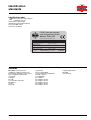
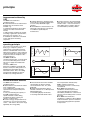
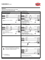
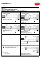
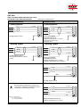
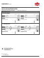
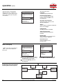
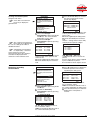
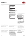
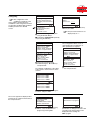
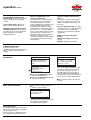
SineWaveª
20 - 480 A
OSF
active harmonics
conditioner
installation and
user manual
To the user
We would like to thank you for choosing the OSF active harmonics conditioner and welcome you to the ever increasing
world-wide family of satisfied FRAKO product users.
This manual has been written to provide you with all the information necessary to install and operate your OSF active
harmonics conditioner.
We remain at your entire disposal should you require any further details.
FRAKO Kondensatoren- und Apparatebau GmbH
Tscheulinstr. 21a l D-79331 Teningen l Germany
Phone +49 7641/453-0 l Fax +49 7641/453-545
http://www.frako.de l E-Mail: info@frako.de
advice for safety
Danger: dangerous voltages are
present inside the conditioner. Any
intervention requiring the door or
protection panels to be opened must be
carried out by qualified personnel;
n the conditioner must be earthed;
n do not place the conditioner near
liquid or in an excessively damp
environment;
0
n do not obstruct the air vents;
n do not place the conditioner in direct
sunlight or near a source of heat;
n if the conditioner in stored before
use, it must be kept in a dry place.
Storage temperature: between -20°C
and +45 °C;
installation and operation manual of OSF
n do not store horizontally;
n dispose of packing waste in
compliance with legal provisions in
force.
FRAKO GmbH
contents
identification ..................................................................................................
3
standards .........................................................................................................
3
principle
improvements offered by OSF ........................................................................... 4
operating principle .................................................................................................. 4
device functional features ...................................................................................... 4
installation
standard arrangements ........................................................................................
installing device(s) ................................................................................................
mechanical characteristics ......................................................................................
installation requirements .........................................................................................
connecting power ....................................................................................................
connecting dry contacts and communication port (optional) ...................................
connecting ribbon cables for 120 A and parallel installation ...................................
moving the graphic terminal ....................................................................................
installing current sensors ....................................................................................
sensor mechanical and electrical characteristics ....................................................
mounting direction of sensors .................................................................................
installing sensors ....................................................................................................
connecting sensors .................................................................................................
5
7
7
8
9
19
20
21
21
21
23
23
26
energization and de-energization
energizing ..............................................................................................................
general ...................................................................................................................
starting the OSF conditioner ...............................................................................
stopping the OSF conditioner .............................................................................
de-energizing .........................................................................................................
27
27
27
27
27
operation
signification of indicator lights ............................................................................
control and monitoring interface .........................................................................
presentation ............................................................................................................
operation .................................................................................................................
general menu ..........................................................................................................
choice of language ..................................................................................................
displaying main measurements ..............................................................................
displaying secondary measurements ......................................................................
displaying alarms ....................................................................................................
configuring ..............................................................................................................
J-BUS communication ............................................................................................
identification ............................................................................................................
RUN-STOP controls ................................................................................................
reserved access ......................................................................................................
28
29
29
29
29
30
30
31
32
33
34
34
34
34
maintenance .................................................................................................... 35
what to do in case of an alarm ............................................................. 35
characteristics and performances .................................................... 36
FRAKO GmbH
installation and operation manual of OSF
1
Installation of the OSF active harmonics conditioner, monitoring of correct operation and certain
repairs must be carried out by qualified personnel trained to deal with electrical hazards. Other operations
may be carried out by any other persons with the help of this manual.
All OSF range products are protected by patents; they implement original technology which cannot
be used by any competitor of FRAKO GmbH.
Copies of this document may be made with the approval of FRAKO GmbH and must bear the
compulsory title FRAKO OSF installation and operation manual
2
installation and operation manual of OSF
FRAKO GmbH
identification
standards
identification label
F
Check that your utility supply is
compatible with the
characteristics given on the
identification label placed inside the
door of the OSF active
harmonics conditioner.
FRAKO Kondensatorenund Anlagenbau GmbH
Aktives Filter OSF
active harmonics filter OSF
OSF 45
Kompensationsstrom:
compensation power: 3 x 45 A
Nennfrequenz:
nominal frequency:
Umgebungstemp.:
ambient temperature: 0 - 40 °C
KT-Nr.:
21451712004
kt number
Nennspannung:
nominal voltage:
320-460 V
46 - 54, 56 - 64 Hz
Artikel-Nr.:
article number:
Fertigungs-Nr.:
serial number:
39-22002
G 9802018
standards
n the OSF active harmonics
conditioner complies with the main
international standards in force for this
type of equipment and notably
concerning:
o design
IEC 146,
o construction and safety:
EN 50091-1,
o noise:
ISO 3746,
o
FRAKO GmbH
installation and operation manual of OSF
protection:
IEC 529, NFC 20010,
o electromagnetic compatibility:
EN 55011 class A,
o susceptibility:
IEC 1000-4-1
IEC 1000-4-2 level 3
IEC 1000-4-3 level 3
IEC 1000-4-4 level 4
IEC 1000-4-5 level 4
IEC 1000-4-6 level 3,
o
quality organisation:
ISO 9001,
o EC marking.
3
principle
improvements offered by
OSF
The OSF active harmonics
conditioner allows:
n current distortion to be reduced and
problems due to harmonics to be
avoided, e.g.:
o unintentional tripping of protections
owing to the value of current in the
neutral,
o cable heating, notably in the neutral,
o heating of generators (transformers,
generator sets, inverters, etc.),
o standards on harmonics consumed
on the utility power not being
respected;
n voltage distortion to be improved as
well as device operating problems due
to over heavily disturbed supply
voltages;
n an installation's characteristics to be
improved so that devices can operate
in conditions specified by the
manufacturer;
n reactive energy to be compensated,
when this type of operation is possible,
and the cosine j to be converted to a
value higher than or equal to 0.94 as
recommended by electricity utilities.
operating principle
The current consumed by a non-linear
load (e.g. a computer system) is
composed of a sinusoidal current IF,
which is a fundamental current at the
utility power frequency, and a harmonic
current IH made up of currents having
frequencies that are multiples of the
network frequency.
The OSF conditioner
continuously generates a current equal
to IH so that the utility power current
only has to supply the fundamental
current.
The load + OSF active
harmonics conditioner assembly will
then be seen by the utility power as a
globally linear load which absorbs
sinusoidal current. Thus, the cabling
and generator impedances will not
introduce any voltage distortion.
0,8
2
1
0
-1
-2
0
-0,8
IF
IF + IH
load
G
IH
OSF
1
0
-1
device functional features
The OSF active harmonics
conditioner allows:
n determination of the harmonic orders
to be compensated:
o by configuring the breadth of the
spectrum to be compensated (H2 to
H25 max.),
o or by concentrating the capacity of
the OSF compensation on
specific harmonic orders during
installation and thus carrying out
selective compensation;
n reactive energy compensation to be
carried out so as to increase the load
cosine j and return to the cosine range
applied by the energy utility;
4
n measurements and other variables
calculated by the device (voltage,
current, distortion rates, etc.) to be
displayed;
n optional communication with an
external controller via a J-BUS protocol
RS422/485 link for:
o transmitting display information,
o receiving RUN and STOP orders.
installation and operation manual of OSF
The compensation introduced by
OSF in relation to harmonic
and reactive currents is continuously
recalculated;
n the OSF active harmonics
conditioner continuously measures
current absorbed by the load and
immediately modifies the current that it
reinjects onto the utility power to match
this value;
n the OSF active harmonics
conditioner is suitable for all installation
load and harmonic spectrum variations
thus guaranteeing optimum operation
at any instant.
installation
standard arrangements
Depending on the type of problem to be
solved, the position of the sensors and
that of the The OSF harmonics
conditioner connection point may be
different from one installation to
another.
The audit carried out before installation
enables the optimum respective
positions to be determined.
n The OSF conditioner is
connected in parallel with the load.
Case of a 20 A, 30 A, 45 A or 60 A unit OSF conditioner
low voltage distribution
switchboard
utility
network
harmonic current
to be compensated
F
The OSF harmonics
conditioner will be fed from a
specific outgoing feeder. This line must
be protected by a circuit-breaker. The
OSF conditioner uses this line
to send harmonics destined to
compensate the load harmonics back
onto the utility power.
current
sensor
load
to be
compensated
harmonic
compensating OSF
current
active
harmonics
conditioner
Case of a 90 A or 120 A unit OSF conditioner
low voltage distribution
switchboard
utility
network
harmonic current
to be compensated
current
sensor
load
to be
compensated
OSF
active
harmonics
conditioner
FRAKO GmbH
installation and operation manual of OSF
5
installation (cont.)
l each conditioner independently uses
current measurements from three
sensors, whatever the state of the other
conditioner; running, stopped, deenergized;
l two cables between the conditioners
allow each to know the otherÕs state
and thus determine the share of
harmonics that it has to supply: half or
all if the other conditioner is not
running;
l each power circuit remains
independent and has its own
protection;
n it is possible to connect up to
l conditioners with the same rating in
parallel to compensate the same load
or the same group of loads.
Case of 2 parallel 20 A, 30 A, 45 A, 60 A, 90 A or 120 A OSF
conditioners
Example of 2 parallel 20, 30, 45 or 60 A OSF conditioners:
low voltage distribution
switchboard
utility
network
harmonic current
to be compensated
current
sensor
load
to be
compensated
OSF
active
harmonics
conditioner
harmonic
compensating OSF
current
active
harmonics
conditioner
Example of 2 parallel 90 or 120 A OSF conditioners:
low voltage distribution
switchboard
utility
network
harmonic current
to be compensated
current
sensor
load
to be
compensated
OSF
active
harmonics
conditioner
OSF
active
harmonics
conditioner
6
installation and operation manual of OSF
FRAKO GmbH
installing device(s)
Mechanical characteristics
W
C1
H
C2
D
dimensions
(mm)
height
H
fixing centre
distance
(mm)
width
W
depth
D
diameter
of fixing
screws
(mm)
mass
(kg)
width
C1
height
C2
475
660
8
65
525
760
8
110
l 20 A and 30 A conditioners
680
540
280
l 45 A and 60 A conditioners
780
590
325
l 90 A and 120 A conditioners are
made up of two cubicles having the
same dimensions as the 45 and 60 A
conditioners. These cubicles can be
placed side by side or on top of one
another (subject to installation
requirements relating to ventilation).
FRAKO GmbH
installation and operation manual of OSF
7
installation (cont.)
Installation requirements
F
The OSF active
harmonics conditioner must
be mounted vertically and away from
any source of heat (heating system,
transformer, motor, etc.).
n it may be installed in a cubicle or
fixed against a wall.
installing a OSF conditioner
alone
n clearances must be provided to allow
the circulation of an air flow:
o 1000 m3 per hour for 20 to 60 A
ratings
o 2000 m3 per hour for 90 to 120 A
ratings.
The air is sucked in below the
conditioner and expelled via the top;
n the air temperature at the inlet of
each conditioner must not exceed
40 degrees (25 °C recommended);
n the power cables and fine wires
arrive via the bottom of the conditioner;
F
Whatever the installation
method, a 600 mm minimum
clearance must be provided in front of
the OSF conditioner allowing
for the door to be completely opened.
300 mm min.
clearance for ventilation
min.
50 mm
clearance
min.
50 mm
clearance
F
To install a 90 A or 120 A
conditioner, refer to how to
install 2 conditioners on top of each
other or side by side.
300 mm clearance
for wiring and
ventilation
Installing 2 OSF conditioners
on top of each other in a cubicle:
Side view
F
Installing 2 OSF
conditioners on top of each
other must only be done inside a
cubicle.
n openings must be provided at the top
and bottom of the cubicle to help the
conditioners to cool down;
n a ventilation deflector must be used
so that the thermal characteristics of
the 2 conditioners are respected. The
distance between the two cubicles is
determined by the height; the air is
sucked below each conditioner and
then expelled:
o out the top for the top conditioner,
o to the rear for the bottom conditioner;
n the air flow required for cooling the
cubicle is 2000 m3 per hour;
n the air temperature at the inlet to
each conditioner must not exceed
40 degrees (25 °C recommended);
n power cables and signal cables
arrive via the bottom of the conditioner.
min. 300 mm clearance
for ventilation
!
!
n
ilatio
vent ctor
defle
m
50 m
min. ance
r
a
le
c
m
50 m
min. ance
r
clea
A (*)
min. 300 mm clearance
for ventilation
A = min. 80 mm : 20 to 30 A ratings
A = min. 200 mm : 45 to 120 A ratings
8
installation and operation manual of OSF
FRAKO GmbH
installing 2 OSF conditioners
side by side
n clearances must be provided to allow
the circulation of an air flow of 1000 m3
per hour per cubicle.
The air is sucked below each
conditioner and then expelled out the
top;
n the air temperature at the inlet to
each conditioner must not exceed
40 degrees (25 °C recommended);
n power cables and signal cables
arrive via the bottom of each
conditioner.
n
min. ventilatio
mm
300 ance for
r
clea
min. m
50 mrance
clea
!
!
min. m
50 mrance
clea
min. m
50 mrance
clea
for
ance
clearntilation
m
m
e
300 g and v
wirin
Connecting power
Determining wiring (not supplied)
Wiring cross-sectional areas shall be
determined in compliance with the
standards in force using the information
in the table opposite and the protection
tables per rating:
care should be taken with neutral cable
sizing, when the neutral is distributed,
owing to the majority presence of third
harmonic which may lead to the current
tripling in the neutral in relation to the
phases.
F
F
The minimum cable cross-sectional areas can be determined based on the
sizing current (Is) given in the tables below.
It is advisable to connect the neutral when it is distributed.
SineWaveª
rating
(A)
Recommended
cross-sectional
areas (mm2) capacity
phases
neutral
terminal block
connection
(mm)
(mm2)
diameter
maximum
of lugs
length of
power cables
(m)
20
30
45
60
90
2,5
4
10
16
10
per cubicle
16
per cubicle
35
35
70
70
70
6
6
8
8
8
20
20
20
20
20
70
8
20
120
16
25
50
70
50
per cubicle
70
per cubicle
Protections (not supplied)
Protections shall be determined in
compliance with the standards in force
using the information below and in
accordance with selectivity
requirements. These models are for
guidance only and do not involve the
responsibility of FRAKO GmbH.
FRAKO GmbH
installation and operation manual of OSF
9
installation (cont.)
OSF 20 A
Table of recommended protections per rating
Connection to the OSF terminal block
where Pcu = function of Isc
Non-distributed neutral
Distributed neutral
IT earthing system
IT earthing system
Is = 25 A
Is = 25 A
1
2
2
3
3
N
C60 3x32 A curve Z IT earthing
system
1
Is = 65 A
N
Is = 25 A
1
Vigi Compact NS100
STR22SE 100 A 4p 3d
magnetic threshold set at 2 x I nom
neutral protection via Vigi
sensitivity: 10 A
TT earthing system
TT earthing system
Is = 25 A
1
2
2
3
3
N
C60 3x32 A curve Z
with Vigi C60 moduleTT earthing
system
Is = 65 A
N
Is = 25 A
1
Vigi Compact NS100
STR22SE 100 A 4p 3d
magnetic threshold set at 2 x I nom
sensitivity: depending on the installation
TNC earthing system
2
3
N
PEN
Is = 65 A
C60 3x32 A curve Z
TNS earthing system
Important: upstream breaking devices should be set in
such a way as to guarantee good discrimination with the
circuit-breakers recommended on this page.
Is = 25 A
1
2
3
Is = 65 A
N
PE
Key: Is = sizing current
Pcu = breaking capacity
Isc = short-circuit current
10
NS100 STR22SE 100 A 4p 3d
magnetic threshold set at 2 x I nom
installation and operation manual of OSF
FRAKO GmbH
OSF 30 A
Table of recommended protections per rating
Connection to the OSF terminal block where Pcu = function of Isc
Non-distributed neutral
Distributed neutral
IT earthing system
IT earthing system
Is = 35 A
Is = 35 A
1
2
2
3
3
N
C60 3x40 A curve Z IT earthing
system
1
Is = 100 A
N
Is = 35 A
1
Vigi Compact NS100
STR22SE 100 A 4p 3d
magnetic threshold set at 2 x I nom
neutral protection via Vigi
sensitivity: 10 A
TT earthing system
TT earthing system
Is = 35 A
1
2
2
3
3
N
C60 3x40 A curve Z
with Vigi C60 moduleTT earthing
system
Is = 100 A
N
Is = 35 A
1
Vigi Compact NS100
STR22SE 100 A 4p 3d
magnetic threshold set at 2 x I nom
sensitivity: depending on the installation
TNC earthing system
2
3
N
PEN
Is = 100 A
C60 3x40 A curve Z
TNS earthing system
Important: upstream breaking devices should be set in
such a way as to guarantee good discrimination with the
circuit-breakers recommended on this page.
Is = 35 A
1
2
3
Is = 100 A
N
PE
Key: Is = sizing current
Pcu = breaking capacity
Isc = short-circuit current
FRAKO GmbH
NS100 STR22SE 100 A 4p 3d
magnetic threshold set at 2 x I nom
installation and operation manual of OSF
11
installation (cont.)
OSF 45 A
Table of recommended protections per rating
Connection to the OSF terminal block
where Pcu = function of Isc
Non-distributed neutral
Distributed neutral
IT earthing system
IT earthing system
Is = 50 A
Is = 50 A
1
2
2
3
3
N
C60 3x63 A curve B IT earthing
system
1
Is = 150 A
N
Is = 50 A
1
Vigi Compact NS160
STR22SE 160 A 4p 3d
magnetic threshold set at 2 x I nom
neutral protection via Vigi
sensitivity: 10 A
TT earthing system
TT earthing system
Is = 50 A
1
2
2
3
3
N
C60 3x63 A curve B
with Vigi C60 moduleTT earthing
system
Is = 150 A
N
Is = 50 A
1
Vigi Compact NS160
STR22SE 160 A 4p 3d
magnetic threshold set at 2 x I nom
sensitivity: depending on the installation
TNC earthing system
2
3
N
PEN
Is = 150 A
C60 3x63 A curve B
TNS earthing system
Important: upstream breaking devices should be set in
such a way as to guarantee good discrimination with the
circuit-breakers recommended on this page.
Is = 50 A
1
2
3
Is = 150 A
N
PE
Key: Is = sizing current
Pcu = breaking capacity
Isc = short-circuit current
12
NS160 STR22SE 160 A 4p 3d
magnetic threshold set at 2 x I nom
installation and operation manual of OSF
FRAKO GmbH
OSF 60 A
Table of recommended protections per rating
Connection to the OSF terminal block
where Pcu = function of Isc
Non-distributed neutral
Distributed neutral
IT earthing system
IT earthing system
Is = 65 A
Is = 65 A
1
2
2
3
3
N
NC100H 3x80 A curve B
1
Is = 200 A
N
Is = 65 A
1
Vigi Compact NS250
STR22SE 250 A 4p 3d
magnetic threshold set at 2 x I nom
neutral protection via Vigi
sensitivity: 10 A
TT earthing system
TT earthing system
Is = 65 A
1
2
2
3
3
N
NC100H 3x80 A curve B
with Vigi C60 moduleTT earthing
system
Is = 200 A
N
Is = 65 A
1
Vigi Compact NS250
STR22SE 250 A 4p 3d
magnetic threshold set at 2 x I nom
sensitivity: depending on the installation
TNC earthing system
2
3
N
PEN
Is = 200 A
NC100H 3x80 A curve B
TNS earthing system
Important: upstream breaking devices should be set in
such a way as to guarantee good discrimination with the
circuit-breakers recommended on this page.
Is = 65 A
1
2
3
Is = 200 A
N
PE
Key: Is = sizing current
Pcu = breaking capacity
Isc = short-circuit current
FRAKO GmbH
NS250 STR22SE 250 A 4p 3d
magnetic threshold set at 2 x I nom
installation and operation manual of OSF
13
installation (cont.)
OSF 90 A with non-distributed neutral
Table of recommended protections per rating
Connection to the OSF terminal block
where Pcu = function of Isc
Non-distributed neutral
IT earthing system
Is = 50 A
Is = 50 A
1
1
2
2
3
3
N
N
C60 3x63 A curve B
C60 3x63 A curve B
TT earthing system
Is = 50 A
C60 3x63 A curve B
with Vigi C60 module
Is = 50 A
1
1
2
2
3
3
N
N
C60 3x63 A curve B
with Vigi C60 module
Important: upstream breaking
devices should be set in such a way
as to guarantee good discrimination
with the circuit-breakers
recommended on this page.
Key: Is = sizing current
Pcu = breaking capacity
Isc = short-circuit current
14
installation and operation manual of OSF
FRAKO GmbH
OSF 90 A with distributed neutral
Table of recommended protections per rating
Connection to the OSF terminal block
where Pcu = function of Isc
Distributed neutral
IT earthing system
Is = 50 A
Is = 50 A
1
2
2
3
Is = 150 A
3
N
Vigi Compact NS160
STR22E 160 A 4p 3d
magnetic threshold set at 2 x I nom
neutral protection via Vigi
sensitivity: 10 A
1
Is = 150 A
N
Is = 50 A
1
Vigi Compact NS160
STR22E 160 A 4p 3d
magnetic threshold set at 2 x I nom
neutral protection via Vigi
sensitivity: 10 A
TT earthing system
Is = 50 A
1
2
2
3
Is = 150 A
3
N
Is = 150 A
N
Is = 50 A
1
Vigi Compact NS160
STR22E 160 A 4p 3d
magnetic threshold set at 2 x I nom
sensitivity: depending on installation
Vigi Compact NS160
STR22E 160 A 4p 3d
magnetic threshold set at 2 x I nom
sensitivity: depending on installation
TNC earthing system
Is = 50 A
1
2
2
3
3
N
PEN
N
PEN
Is = 150 A
Is = 150 A
C60 3x63 A curve B
C60 3x63 A curve B
TNS earthing system
Is = 50 A
Is = 50 A
1
2
2
3
Is = 150 A
3
Is = 150 A
N
PE
NS160 STR22E 160 A 4p 3d
magnetic threshold set at 2 x I nom
1
N
PE
NS160 STR22E 160 A 4p 3d
magnetic threshold set at 2 x I nom
Important: upstream breaking devices should be set in such a way as to guarantee good discrimination with the circuit-breakers recommended
on this page.
FRAKO GmbH
installation and operation manual of OSF
15
installation (cont.)
OSF 120 A with non-distributed neutral
Table of recommended protections per rating
Connection to the OSF terminal block
where Pcu = function of Isc
Non-distributed neutral
IT earthing system
Is = 65 A
Is = 65 A
1
1
2
2
3
3
N
N
NC100 3x80 A
curve B
NC100 3x80 A
curve B
TT earthing system
Is = 65 A
NC100 3x80 A
curve B
with Vigi C60 module
for NC100
Is = 65 A
1
1
2
2
3
3
N
N
NC100 3x80 A
curve B
with Vigi C60 module
for NC100
Important: upstream breaking
devices should be set in such a way
as to guarantee good discrimination
with the circuit-breakers
recommended on this page.
Key: Is = sizing current
Pcu = breaking capacity
Isc = short-circuit current
16
installation and operation manual of OSF
FRAKO GmbH
OSF 120 A with distributed neutral
Table of recommended protections per rating
Connection to the OSF terminal block
where Pcu = function of Isc
Distributed neutral
IT earthing system
Is = 65 A
Is = 65 A
1
2
2
3
Is = 200 A
1
3
N
Is = 200 A
N
Is = 65 A
1
Vigi Compact NS250
STR22E 250 A 4p 3d
magnetic threshold set at 2 x I nom
neutral protection via Vigi
sensitivity: 10 A
Vigi Compact NS250
STR22E 250 A 4p 3d
magnetic threshold set at 2 x I nom
neutral protection via Vigi
sensitivity: 10 A
TT earthing system
Is = 65 A
1
2
2
3
Is = 200 A
3
N
Is = 200 A
N
Is = 65 A
1
Vigi Compact NS250
STR22E 250 A 4p 3d
magnetic threshold set at 2 x I nom
sensitivity: depending on installation
Vigi Compact NS250
STR22E 250 A 4p 3d
magnetic threshold set at 2 x I nom
sensitivity: depending on installation
TNC earthing system
Is = 65 A
1
2
2
3
3
N
PEN
N
PEN
Is = 200 A
Is = 200 A
NC100H 3x80A curve B
NC100H 3x80A curve B
TNS earthing system
Is = 65 A
Is = 65 A
1
2
2
3
Is = 200 A
3
Is = 200 A
N
PE
NS250 STR22E 250 A 4p 3d
magnetic threshold set at 2 x I nom
1
N
PE
NS250 STR22E 250 A 4p 3d
magnetic threshold set at 2 x I nom
Important: upstream breaking devices should be set in such a way as to guarantee good discrimination with the circuit-breakers recommended
on this page.
FRAKO GmbH
installation and operation manual of OSF
17
installation (cont.)
Connection operations:
Connection operations must be
carried out without the
conditioners being energized.
For the protection of persons,
remember that the PE or PEN
protective conductor must always be
connected first.
Earthing system: OSF is suited
to all types of earthing system.
Procedure:
n check that the lifting sling has been
removed;
n check that the OSF supply
circuit-breaker placed in your low
voltage switch cubicle is in open
position (O);
n wiring is connected via the bottom, in
front of the conditioner;
n to access the connection terminal
block, remove the front and lower
protection plates;
n power connections are made on the
bolted terminal block;
n the lower protection plate of the
power terminal block must be fitted with
bushings for cable feedthrough. If
several holes are made to feed the
cables through, cut a slot common to all
the holes to prevent eddy currents from
being generated;
front protection
plate
lower protection
plate
PE
neutral
phase 1
phase 2
phase 3
n connect the PE or PEN conductor
first;
n connect the other conductors so that
they comply with the rotation direction
of the phases and the indications in the
figures opposite.
F
The connecting cables must be
mechanically fixed near the
terminal block so that any mechanical
stress on the conductors is prevented.
Note:
If there is traction on the cables, the PE
or PEN must be the last conductor
subject to its effects.
18
installation and operation manual of OSF
FRAKO GmbH
Connecting dry contacts and
communication port (optional)
connector
cross-sectional
area
(mm2)
type of
recommended
conductor
remark
dry contact terminal
block
0.5 mini
2.5 max
multi-core wires
(not supplied)
removable screw terminal
block (supplied)
9 point Sub-D
shielded cable
(not supplied)
Determining wiring
male connector with female
contacts on OSF
;
the shielding must be
connected at both ends.
Connection operations
Procedure:
n wiring is connected via the bottom, in
front of the device.
F
Signal cable connections must
be mechanically fixed near the
connectors so that any mechanical
stress on the conductors is prevented
10
10
1
1
10
1
n configuration of dry contact terminal
block:
o 2 x voltage-free changeover
switches: conditioner running/stopped,
o 1 x voltage-free changeover switch:
current-limiting operation;
n connection to the terminal block may
be made whilst OSF is operating;
n these contacts comply with safe extra
low voltage insulating requirements.
dry contact cable
(not supplied)
removable connector
with polarization
(supplied with conditioner)
10
common
9
conditioner stopped
8
conditioner
running
7
common
6
normal operation
5
limiting operation
4
common
3
conditioner stopped
2
conditioner running
1
F
communication link (optional)
(not supplied)
NO
NC
NO
NC
NO
NC
Contact breaking capacity:
P = 2 VA, U = 30 V max.,
I = 1 A max.
n configuration of 9 point Sub-D
connector for RS 422/485
communication link (optional);
n the communication link can be
plugged into the sub-D connector
without shutting down the OSF ;
n this interface complies with safe extra
low voltage insulating requirements.
OSF connector
seen from below
1
2
6
FRAKO GmbH
3
7
5
4
8
9
installation and operation manual of OSF
Key:
pin 1: 0 volts
pin 2: RP_5V
pin 3: RC_A
pin 4: RDÐ(BÕ)
pin 5: TDÐ(B)
pin 6: RP_0V
pin 7: RC_B
pin 8: RD+(AÕ)
pin 9: TD+(A)
19
installation (cont.)
Connecting ribbon cables for the
90 or 120 A and for parallel
installation
Type of connections
connector
type of conductors
remark
OSF 90 or 120 A
inter-cubicle connector
shielded strand supplied (3 m)
connection between the 2 cubicles which make
up the OSF 90 or 120 A
OSF parallel connector
shielded strand supplied (5 m)
loop connection allows parallel operation of the OSF
even if it is interrupted for the number of devices to be modified
Connection operations for parallel or
90 A or 120 A conditioners
20 A or 60 A parallel
conditioner connection
90 A or 120 A parallel conditioner
connection
Connection operations must be
carried out with the
conditioner de-energized.
MERY
board
Procedure:
n wiring is connected via the bottom, in
front of the device;
n remove the protection plate;
n the conductor connectors must be
correctly locked;
n shielding shall be earthed in
compliance with the indications given
below;
PARY
board
MERY
board
1 cable for controlling
the 2nd 90 A or 120 A
cubicle
PARY
board
2 strands for
parallel connection
2 strands for parallel
connection
connector
shielding
90 A or 120 A parallel
conditioner connection
2nd 90 or 120 A conditioner
cubicle connection
shielding
earthing
block
90 A or 120 A
OSF
inter-cubicle
connection
MERY
board
PARY
board
n configure the parallel connection
board using the indications in the table
below.
F
Signal cables connections
must be mechanically fixed
near the connectors so that any stress
on the conductors or conductor
shielding earthing is prevented.
DUMY
board
1 cable for controlling the 2nd
90 A or 120 A cubicle
cable coming from the 1st
90 A or 120 A cubicle
Close-up of connectors
MERY board
inter-cubicle
connector
connection between two
boards
parallel installation connectors
2 equivalent connectors
20
installation and operation manual of OSF
PARY board
configuration straps and
switches for parallel
connection
FRAKO GmbH
Table of strap configurations for each parallel conditioner
OSF number 1
configuration
of parallel
conditioners
OSF number 2
OSF number 3
OSF number 4
1
1
1
1
4
4
4
4
Moving graphic terminal
The OSF harmonics
conditioner graphic terminal can be
moved to the front panel of a switch
cubicle where a OSF is installed.
Cutting and fixing template for the
moved terminal
cut
n To do this, use the optional kit
reference n° 5102726400 which
contains:
o a cover plate replacing the terminal
located on the OSF door,
o a 2.5 metre long extension lead. This
lead cannot be lengthened without this
causing a risk of abnormal operation;
n Moving the graphic terminal:
o disconnect the terminal ribbon cable
on the back of the door,
o remove the terminal by unscrewing
the 4 fixing screws,
o use these 4 screws to fix the cover
plate in place of the terminal,
o connect the ribbon cable onto the
extension lead,
o feed the extension lead through the
rectangular bushing at the bottom of
the OSF conditioner,
o fix the terminal at the required
location,
o connect the extension lead to the
graphic terminal.
116
129
4 x D3.4
66
70
installing current sensors
(supplied)
Once installed, the current sensor
secondaries must be short-circuited via
the pullout terminals, or equivalent
terminals (not supplied). These pullout
terminals will remain in closed position
as long as they are not connected to
the OSF conditioner.
Sensor mechanical and electrical
characteristics
Closed sensors:
Important: the shape of the sensor
may be different depending on the
rating and supplier.
A
H2
B1 H1
P
B2
L
FRAKO GmbH
installation and operation manual of OSF
21
installation (cont.)
rating
external
dimensions
H1 / H2 / L / P
(mm)
primary
secondary
B1 / B2
(mm)
max. cable
diameter
diameter
of lugs
(A)
3 or 5
depending
on supplier
3 or 5
depending
on supplier
3 or 5
depending
on supplier
3 or 5
depending
on supplier
3 or 5
depending
on supplier
3 or 5
depending
on supplier
300/1
500 / 1
76 / 106
76 / 44
31 / 11
23
1000/1
90 / 106
77 / 44
41 / 11
31
1500/1
165 / 194
95 / 40
103 / 22
rod only
2000/1
165 / 194
95 / 40
103 / 22
rod only
3000/1
180 / 209
115 / 45
103 / 32
rod only
4000/1
180 / 209
115 / 45
103 / 32
rod only
Opening sensors:
On wiring kit supplied:
S1 = blue
S2 = brown
The sensors must be closed and
screwed on both sides.
600/1 sensor: it is advisable to fix the
sensor onto the cable. Fixing lugs are
provided for this purpose.
cross-sectional
area of wires
(twisted 2-core
cables)
(mm2)
0.75 min.
0.75 recommended
2.5 max.
0.75 min.
0.75 recommended
2.5 max.
0.75 min.
0.75 recommended
2.5 max.
0.75 min.
0.75 recommended
2.5 max.
0.75 min.
0.75 recommended
2.5 max.
0.75 min.
0.75 recommended
2.5 max.
max. length
of wires
(not supplied)
(m)
20
20
20
20
20
20
2000/1 sensor
600/1 sensor
L
L
D1
D1
D2
D2
P
S1 S2
S1 S2
P
D3
E
rating
600/1
2000/1
22
primary
secondary
dimensions
(mm)
external
fixing centre
distance C
(mm)
diameter of
screws
(mm)
max. cable
diameter
fine wire
connection
D2 = 96.5
L = 128
P = 35
D2 = 137.5
L = 298
P = 34
60
6
D1 = 48
wiring kit supplied 0.75 min.
(5 m)
0.75 recommended
2.5 max.
wiring kit supplied 0.75 min.
(5 m)
0.75 recommended
2.5 max.
D1 = 69
or rod D1 = 69
D3 = 206
installation and operation manual of OSF
cross-sectional
area of wires
(2-core cables)
max. length
of wires
(m)
20
20
FRAKO GmbH
mounting direction of sensors
F
The current sensors must be
mounted on each of the
phases supplying the load.
They must be mounted in the direction
shown in the figure opposite.
P2
load
phase 1
P1
P2
load
phase 2
P1
P2
load
phase 3
P1
load
neutral
load
PE or PEN
installing sensors
For a 20 A, 30 A, 45 A or 60 A unit:
Once installed, the current
sensor secondaries must be
short-circuited via the pullout terminals,
or equivalent terminals. These pullout
terminals will remain in closed position
as long as they are not connected to
the OSF conditioner - see
diagrams opposite.
n an intermediary terminal block (not
supplied) must be installed for the 3
current sensors;
n it enables each of the 3 secondaries
to be short-circuited;
n the OSF conditioner shall be
connected to this terminal block.
phase 1
to
load
phase 2
phase 3
see fig. 1
shorting links
ard
Y bo
MER
TIFY
board
XR1
XR2
XR3
1 terminal block
not supplied
Fig. 1
MERY board
XR1
XR2
XR3
XR2
XR3
TIFY board
XR1
S1
S2
phase 1
FRAKO GmbH
S1
S2
phase 2
installation and operation manual of OSF
S1
S2
phase 3
23
installation (cont.)
n an intermediary terminal block (not
supplied) must be installed for the 3
current sensors:
n it enables each of the 3 secondaries
to be short-circuited;
n the OSF onditioner shall be
connected to this terminal block.
For a 90 A or 120 A unit:
phase 1
phase 2
to
load
phase 3
see fig. 1
ard
Y bo
MER
TIFYd
boar
XR1
1 terminal block
XR2
Y
DUMd
boar
XR3
not supplied
Fig. 1
MERY board
XR1
XR2
XR3
XR2
XR3
TIFY board
XR1
S1
S2
phase 1
24
S1
S2
phase 2
S1
S2
phase 3
installation and operation manual of OSF
FRAKO GmbH
n an intermediary terminal block (not
supplied) must be installed for the 3
current sensors:
n it enables each of the 3 secondaries
to be short-circuited;
n one of the OSF conditioners
shall be connected to this terminal
block;
n the connection leads supplied with
the conditioners will allow the
OSF conditioners to operate in
parallel via loop communication.
For 90 A or 120 A parallel units:
phase 1
phase 2
to
load
phase 3
ard
Y bo
MER
d
boar
PARY
see fig. 1
1 terminal block
not supplied
rd
Y boa
MER
rd
Y boa
MER
board
PARY
board
PARY
XR1
XR2
XR3
Fig. 1
PARY board
XR1
S1
XR2
S2
phase 1
FRAKO GmbH
S1
XR3
S2
phase 2
S1
S2
phase 3
installation and operation manual of OSF
25
installation (cont.)
n an intermediary terminal block (not
supplied) must be installed for the 3
current sensors:
n it enables each of the 3 secondaries
to be short-circuited;
n one of the control OSF
conditioners shall be connected to this
terminal block;
n the connection leads supplied with
the conditioners will allow the
OSF conditioners to operate in
parallel via a loop communication;
n other leads supplied with the
conditioners will ensure connections
between the two cubicles which make
up each 120 A.
For 90 A or 120 A parallel units:
phase 1
phase 2
to
load
phase 3
Y
DUMd
boar
Y
DUMd
boar
ard
Y bo
MER
rd
Y boa
MER
1 terminal block
not supplied
see fig. 1
board
PARY
board
PARY
Fig. 1
PARY board
XR1
S1
XR2
S2
phase 1
S1
XR3
S2
phase 2
S1
S2
phase 3
Connecting sensors
Connection operations
F
The signal cables connecting
the current sensors to the
OSF conditioner must be
moved away from the power cables so
that any disturbance is avoided.
26
Procedure:
n wiring is connected via the bottom, in
front of the conditioner;
n the signal cables connections are
made on 3 screw terminals.
installation and operation manual of OSF
F
The signal cables must be
mechanically fixed near the
terminals so that any mechanical stress
on the conductors is avoided:
n put back the protection panels and
close the door;
n close the OSF conditioner
protection circuit-breaker.
FRAKO GmbH
energization and de-energization
F
The conditioner must be
energized for the first time by
qualified FRAKO
personnel who will carry out the
necessary checks to make sure that
operation of the installation is optimum.
energization
l close the conditioner supply circuitbreaker on your low voltage supply
switchboard:
n the "conditioner stopped" red
indicator lamp lights up;
n the terminal screen lights up;
n after several seconds, the general
menu is displayed on the terminal
screen.
general
l if the load harmonic current is higher
than the OSF's capacity to
eliminate harmonics, the orange
indicator lamp will flash, whether the
conditioner is running or stopped;
l to access the RUN and STOP keys,
remove the protection cover located at
the bottom of the terminal;
l OSF starting and stopping
can be controlled manually using the
terminal keyboard or via the
communication link;
l if OSF conditioners are
connected in parallel, each conditioner
can be started or stopped
independently of the others.
starting the SineWaveª
conditioner
l Press the RUN key on the terminal to
start the OSF conditioner and
then confirm the command displayed
on the terminal by pressing the ENT
key.
l the OSF conditioner starts
and is then operational. The red
indicator lamp goes off and the green
lamp lights up.
stopping the SineWaveª
conditioner
l to stop the OSF conditioner
manually, press the STOP key and
confirm the displayed command be
pressing the ENT key on the terminal;
F1
F2
F3
7
8
9
4
5
6
ESC
1
2
3
ENT
0
RUN STOP
protection
cover
F
The OSF conditioner
will be automatically restarted
when energized following
disappearance of the utility voltage
during operation of the OSF
conditioner. If it is not energized
following the disappearance of the
utility voltage, the OSF
conditioner will remain stopped.
l the OSF conditioner stops
and no longer carries out
compensation. The green indicator
lamp goes off and the red indicator
lamp lights up.
de-energization
The OSF conditioner can be
de-energized whatever its state:
running or stopped.
FRAKO GmbH
installation and operation manual of OSF
27
operation
signification of indicator
lamps
User interface
simple
indications
The conditioner's operating state is
given by common indications
F1
F2
F3
7
8
9
4
5
6
ESC
1
2
3
ENT
0
RUN STOP
Common
indications
user-friendly interface
green indicator: conditioner running
orange indicator: conditioner limiting current
red indicator: conditioner stopped
These clearly indicate:
l normal operation: green indicator
lamp lit.
The OSF conditioner is
eliminating harmonics on the utility
power. This is its normal operating
state;
l conditioner stopped: red indicator
lamp lit.
The conditioner has stopped following a
manual STOP command or an
operating anomaly. Consult the user
interface to know what the fault is due
to and what action to undertake in order
to correct the anomaly;
l current-limiting operation: green
indicator lamp lit and orange indicator
lamp flashing.
28
installation and operation manual of OSF
The harmonic RMS current absorbed
by the load exceeds the OSF
nominal current. The conditioner thus
operates in current-limiting mode:
n the conditioner limits its
compensating current to its nominal
current rating (e.g. 30 A RMS for a 30 A
OSF conditioner),
n the load is not entirely compensated,
n the harmonic current difference (load
harmonic I - compensating I) remains
on the utility power,
n consult the chapter on "what to do in
case of an alarm".
FRAKO GmbH
control and monitoring
interface
Presentation
Front view of terminal
The OSF active harmonics
conditioner has a highly user-friendly
graphic terminal on the front panel
which makes the product easy to use.
This terminal may optionally be moved
to the front panel of a switch board from
the conditioner using a separate supply
cable.
This terminal allows:
n the language of the displayed
messages to be chosen from a
selection of 7 languages;
n the conditioner identification and
operating parameters to be clearly
displayed;
n the OSF configuration to be
modified to better meet specific
applications;
n conditioner operation to be
controlled.
Back view of terminal
1
3
F1
F2
F3
7
8
9
4
5
6
ESC
1
2
3
ENT
0
2
RUN STOP
1 Liquid crystal graphic display with
back lighting (128 x 64 points, i.e.
6 lines of 21 characters) allowing
information to be displayed.
3 9 point SUB-D connector for
connecting the terminal to the
OSF conditioner.
2 20-key keyboard
ENT key (enter)
ESC key (escape)
p and q keys
number keys: 0 to 9 and
decimal point
function keys: F1, F2, F3
command keys: RUN and
STOP protected by a removable
protective cover.
Use
n ENT key:
o move to following menu,
o confirmation of a choice;
n ESC key:
o return to previous menu,
o cancellation of parameter setting in
process and return to original values;
n p and q keys:
o scrolling and selection from menu
o choice of parameter,
o setting of value (use in + or -)
General menu
A menu is a screen offering a list of
options and possible choices.
n to select something from the menu:
o use the p and q keys to choose the
required option,
o press ENT to confirm the chosen
option.
FRAKO GmbH
n number keys from 0 to 9 and
decimal point
o entering of passwords,
o entering of numerical values;
n function keys F1, F2, F3:
o F1 provides access to the help menu,
o the functions of F2 and F3 depend on
the menu displayed;
When a menu offers more than
4 options, the presence of the q
symbol at the bottom of the screen
indicates that the menu continues onto
another screen.
installation and operation manual of OSF
n RUN and STOP keys
RUN: conditioner local RUN
command,
o STOP: conditioner local STOP
command.
o
The p arrow is used to move back up
the menu.
29
operation (cont.)
The main menu is automatically
displayed when the equipment is
energized. It can also be accessed
from a sub-menu by pressing ESC
several times.
The main menu offers:
Language:
available languages displayed.
MAIN MENU
Language / langue
Principle measurements
Secondary measurements
Alarms
Principle measurements:
I r.m.s., load and network THDI,
network voltage and OSF load
rate displayed.
Configuration
JBUS communication
Identification
Reserved access
Secondary measurements:
detailed load and network current
spectrum displayed.
Alarms:
alarms and level 1 diagnosis displayed,
faults acknowledged.
Configuration:
operating parameters modified.
JBUS communication:
communication port parameters
modified.
Identification:
main conditioner characteristics and
software versions displayed.
Reserved access:
access to FRAKO service
personnel only.
Choice of language
F
Press ESC several times if
necessary to display the
main menu.
MAIN MENU
CHOICE OF LANGUAGE
French
Deutsch
English
Espa–ol
Language / langue
Principle measurements
Secondary measurements
Alarms
Configuration
JBUS communication
Identification
Reserved access
Nederlands
Italiano
US English
3 Choose the language using the p
and q keys and confirm via ENT
1 Choose the Language option using
the p and q keys. The choice must
be displayed in reverse video.
2 Confirm the language option by
pressing ENT.
Displaying main measurements
Locating measurement points
U, I, THDI
U, I, THDI
deformed
load to be
compensated
utility
network
load %
OSF
30
installation and operation manual of OSF
FRAKO GmbH
Locating measurement points
Using the main menu
F
Press ESC several times if
necessary to display the
general menu:
MAIN MENU
Language / langue
Principle measurements
Secondary measurements
Alarms
Configuration
JBUS communication
Identification
Reserved access
F
F
The current measurements in
the neutral are not displayed in
the case of a utility power without
distributed neutral.
Insignificant measurements
are replaced by * characters
on the terminal screen and
measurements where the capacity is
exceeded are displayed with #
characters on the terminal screen.
Displaying secondary
measurements
1 Choose the Principle
measurements option using the p
and q keys. The choice must be
displayed in reverse video.
2 Confirm the Principle
measurements option by pressing
the ENT key.
MAINS
LOAD
I1 = xxxA
I2 = xxxA
I3 = xxxA
IN = xxxA
I1 = xxxA
I2 = xxxA
I3 = xxxA
IN = xxxA
I1, I2, I3, IN = actual root mean square
values in amps of the 3 phases and
neutral of the:
n current supplied by the utility power;
n current absorbed by the non-linear
load.
MAIN MENU
Language / langue
Principle measurements
Secondary measurements
Alarms
Configuration
JBUS communication
Identification
Reserved access
1 Choose the Secondary
measurements option using the p
and q keys.
2 Confirm the Secondary
measurements option by pressing
the ENT key.
3 Press the p and q keys to run over
the main measurement screens:
circular loop display.
MAINS
LOAD
THDI1=xx% THDI1=xx%
THDI2=xx% THDI2=xx%
THDI3=xx% THDI3=xx%
Umains=xxxV
THDI1, THDI2, THDI3 = distortion rates
of the 3 phases (THDI = I-harmonic/Ibasic) of the:
n current supplied by the utility power;
n current absorbed by the non-linear
load.
Umains = average value of the 3 utility
network phase-to-phase voltages.
LOAD LEVEL SINEWAVE
I1 / In = xxx%
I2 / In = xxx%
I3 / In = xxx%
I1/In, I2/In, I3/In = OSF active
conditioner load rates on each of the
phases.
I1 = root mean square current supplied
by the conditioner on phase 1,
In = nominal root mean square current.
3 Press p and q arrows to display the
detailed spectrum of the current
supplied by the utility power.
I1 MAINS SPECTRUM
H1
H3
H5
H7
=
=
=
=
xx%
xx%
xx%
xx%
I2
H9 = XX%
H11 = xx%
H13 = xx%
THDI = xx%
I3
H1, H3 - H13 = detailed spectrum of
first 13 harmonic orders.
THDI = total harmonic distortion rate of
the current supplied by the utility power.
4 Press the function keys F2 and F3 to
display phase 2 and phase 3
currents.
I1 LOAD SPECTRUM
H1
H3
H5
H7
=
=
=
=
xx%
xx%
xx%
xx%
I2
H9 = XX%
H11 = xx%
H13 = xx%
THDI = xx%
I3
H1, H3 - H13 = detailed spectrum of
first 13 harmonic orders.
THDI = total harmonic distortion rate of
the current absorbed by the load.
FRAKO GmbH
installation and operation manual of OSF
31
operation (cont.)
Displaying alarms
MAIN MENU
Language / langue
Principle measurements
Secondary measurements
Alarms
Configuration
JBUS communication
Identification
Reserved access
1 Choose the Alarms option using the
p and q keys. The choice must be
displayed on the screen in reverse
video.
2 Confirm the Alarms option by
pressing the ENT key.
The following screen is displayed
during normal operation: conditioner
running and no anomaly present.
In the event of an operating anomaly,
the following screen is displayed with
the active alarms only.
ALARMS
ALARMS
No Alarm
SineWave
Keeps your electrical
AC network clean
Start-up inhibited
MERY PC board fault 1
Internal fault
Voltage out of tol.
?
Diag.
Reset
Frequency out of tol.
MERY PC board fault 2
Phase rotation WRONG
Internal overtemp
Harm current >Inom
Conditioner OFF
The p and q keys allow 2 pages of
faults to be displayed. The F2 "Diag"
key provides access to the level 1
diagnosis and the F3 "Reset" key
allows memorised faults to be
acknowledged.
List of alarms displayed:
MERY PC board fault 1: the main
control and monitoring board is faulty.
The board must be replaced by the
FRAKO after-sales service.
Frequency out of tol.: the utility power
frequency is out of the permitted limits.
Check the utility power frequency. The
frequency tolerances permitted are
defined in the section on
"characteristics and performances".
Internal fault: this message informs
the user of an internal conditioner fault
which requires intervention by the
FRAKO after-sales service.
MERY PC board fault 2: the main
control and monitoring board is faulty.
The board must be replaced by the
FRAKO after-sales service.
Voltage out of tol.: the amplitude of
the utility network voltage is out of the
permitted limits. Check the presence
and amplitude of the utility power
3 phases and neutral. The voltage
tolerances permitted are defined in the
section on "characteristics and
performances".
32
Internal overtemp: the conditioner has
been stopped by the thermal protection
thus avoiding damage to the
equipment. Check that the 3 ventilators
are operating correctly, that the air
vents are clean and check the
temperature of the room. The
temperature tolerances permitted are
defined in the paragraph on
"characteristics and performances".
installation and operation manual of OSF
Harm current > I nom: the harmonic
root mean square current absorbed by
the load exceeds the OSF
conditioner nominal current making it
operate in current-limiting mode.
n the conditioner limits its
compensating current to its nominal
current rating (e.g. 30 A root mean
square for a 30 A OSF
conditioner);
n the load is not entirely compensated;
n the harmonic current difference (load
harmonic I - compensating I) remains
on the utility power;
n problems may occur in your
installation depending on the rate of
harmonics remaining on the utility
power;
n consult the FRAKO
after-sales service.
FRAKO GmbH
Configuring
F
The configuration of the
conditioner carried out in the
factory will be checked when the
conditioner is first energized, and must
not be further modified. Only qualified
FRAKO personnel are allowed
access.
MAIN MENU
Language / langue
Principle measurements
Secondary measurements
Alarms
Configuration
JBUS communication
Identification
Reserved access
1 Choose the Configuration option
using the p and q keys.
2 Confirm the Configuration option by
pressing the ENT key.
CONFIGURATION MENU
Current sensor 1000/1
Neutral connected
ON/OFF JBUS validated
Reactive compensated
?
Mem
Harmonics choice
Application: 0005
Nb of // units: 2
Mains voltage: 400 V
Derating %: 10
Sensor connected
4 Choose the parameter to be
modified using the p and q keys
and press ENT.
For example, modification of the rating
of the sensors used to measure load
currents.
CONFIGURATION
Enter
password:
****
3 Enter the password (4 characters)
then press ENT.
F
The password characters are
displayed by an "*".
The Configuration Menu screen is
again displayed for modification of
other parameters if required
CONFIGURATION MENU
Current sensor 1000/1
Neutral connected
ON/OFF JBUS validated
Reactive compensated
?
Mem
Harmonics choice
Application: 0005
Nb of // units: 2
Mains voltage: 400 V
Derating %: 10
Sensor connected
6 Press F2 "Mem" key to memorise
the new parameters.
SENSOR SIZE CHOICE
Current
Current
Current
Current
sensor
sensor
sensor
sensor
300/1
500/1
600/1
1000/1
Current
Current
Current
Current
sensor
sensor
sensor
sensor
1500/1
2000/1
3000/1
4000/1
5 Choose the sensor rating using the
arrows and press ENT.
The screen opposite is displayed after
pressing F2 to confirm memorisation of
the new parameters
MEMORIZATION
MEMORIZATION
Confirmation: ENT
Escape: ESC
WARNING: Memorization
= STOP of SineWave
Memorization in progress
7 Confirm memorization by pressing
ENT or cancel modifications in
progress by pressing ESC.
FRAKO GmbH
installation and operation manual of OSF
This screen is displayed while the
parameters are being saved, wait a few
seconds for the general menu to be
displayed before starting the
OSF up again.
33
operation (cont.)
Configuration parameter lists
Sensor rating: choose the rating of the
sensors used to measure the load
currents.
Type of utility power: utility power
with or without distributed neutral.
RUN/STOP authorisation via JBUS
communication port: authorisation or
non authorisation of remote RUN and
STOP commands via the JBUS
communication port.
Reactive compensation or no
reactive compensation:
compensation or no compensation of
the reactive energy. If this option is
confirmed the amount of reactive
energy supplied by the network can be
reduced and penalty payments in
preferential tariff contracts avoided.
Compensation is optimised increasing
the value of cos F to a value higher
than or equal to 0.94. Reactive energy
compensation is carried out to the
detriment of harmonic compensation
and it is therefore necessary to
oversize the conditioner if it is required
to compensate both reactive energy
and harmonics.
Choice of compensated harmonic
orders:
if this option is selected, the harmonic
orders to be compensated, in order to
optimise conditioner performance, can
be chosen.
Choice of application type: the choice
of application type is a parameter which
is set in the factory. It is defined in
relation to the customerÕs installation
configuration.
Number of parallel-connected
devices.
Utility power voltage: load supply
voltage
Derating: depending on altitude.
J-BUS communication
Parameter setting of the
communication port is described Is the
specific J-BUS communication port
manual.
Identification
MAIN MENU
Language / langue
Principle measurements
Secondary measurements
Alarms
Configuration
JBUS communication
Identification
Reserved access
1 Choose the Identification option
using the p and q keys.
2 Confirm the Identification option by
pressing the ENT key.
RUN - STOP commands
IDENTIFICATION
N° = xxxxxxxxxxxx
Is = xxxA
Un = xxxV
Fn = xxHz With neutral
Versions = xx, xx
This screen displays the device serial
number, the nominal current in amps,
the nominal voltage in volts, the
nominal frequency in Hz, the type of
network (with or without distributed
neutral) and the software versions built
into the control and monitoring board.
3 Press ESC to return to the general
menu.
1 Press RUN to start the device or
STOP to stop the device.
START-UP
Confirmation: ENT
Escape: ESC
This screen allows the command to be
confirmed by pressing ENT or
cancelled by pressing ESC.
Reserved access
This command provides access to the
centre of the system and is for FRAKO
personnel only so that
they may carry out a detailed survey of
the conditionerÕs internal operation.
34
installation and operation manual of OSF
FRAKO GmbH
maintenance
what to do in case of an alarm
maintenance
Before any intervention:
n in the OSF conditioner:
switch off the power supply and wait for
the capacitors to discharge (5 min.);
n on the current sensor connection:
short-circuit the sensor secondaries.
The OSF harmonics
conditioner does not require any
preventive maintenance.
It is nevertheless advisable to carry
out the following at regular intervals:
n clean the air vents and check that
ventilation is efficient;
n check the state and tightness of
connections;
n make sure that the temperature of
the air at the OSF conditioner
inlet is below 40 degrees.
what to do Is case of an
alarm
symptoms
corrective actions
terminal and indicator lamps off
check the voltage at the OSF conditioner input.
The voltage tolerances permitted are defined in the section on "characteristics and performances".
terminal OFF
check that the graphic terminal is plugged in.
MERY PC board fault 1
ask the FRAKO after-ales service to intervene.
MERY PC board fault 2
ask the FRAKO after-ales service to intervene.
internal fault
ask the FRAKOafter-ales service to intervene.
voltage out of tol.
check the voltage at the conditioner inlet. The voltage tolerances permitted are defined in the
section on "characteristics and performances".
frequency out of tol.
check the frequency at the conditioner inlet. The voltage tolerances permitted are defined in the
section on "characteristics and performances".
internal overtemp
check ventilator operation, the temperature inside the room and the cleanliness of the air vents.
The temperature tolerances permitted are defined in the section on "characteristics and
performances".
orange indicator lamp flashing
the conditioner is limiting current because the installation's compensation need is higher than the
current that the conditioner can supply. The conditioner automatically protects itself.
Compensation is not total.
FRAKO Kondensatoren- und Apparatebau GmbH
Tscheulinstr. 21a l D-79331 Teningen l Germany
Phone +49 7641/453-0 l Fax +49 7641/453-545
http://www.frako.de l E-Mail: info@frako.de
FRAKO GmbH
installation and operation manual of OSF
35
characteristics and performances
technical reference base:
active conditioner
characteristics (07/03/97
version)
Unless otherwise stipulated, the
performances given Is the table below
are typical values corresponding to use
under a nominal utility power voltage of
400 V three-phase, at 50 Hz, at the
nominal current.
network input
functions
operating mode
technical characteristics
n nominal voltage
n nominal frequency
n number of phases
n harmonic compensation
n power factor compensation
n cosine F compensation
n single
n connected in parallel
n compensation capacity per phase
o 400 V -20% + 15%
o 50 Hz, 60 Hz +/- 4 Hz
o 3 phases with or without distributed neutral,
operation possible on single-phase or unbalanced
loads.
o global or order by order
o possible to set parameters
o up to 4
o 20 A r.m.s
o 30 A r.m.s
o 45 A r.m.s
o 60 A r.m.s
o 90 A r.m.s
n compensation capacity in neutral conductor
n compensated harmonic orders
n dynamic capacity in dI/dt:
n response time
n reduction rate
n overload
n inrush current
n losses
n ventilation
n acoustic noise
according to ISO 3746
environmental conditions
36
n ambient temperature
n rate or relative humidity
n operating altitude
installation and operation manual of OSF
o 120 A r.m.s
note: the compensation capacity decreases with
the frequency of the harmonic orders to be
compensated.
o 60 A r.m.s.
o 90 A r.m.s.
o 135 A r.m.s.
o 180 A r.m.s.
o 270 A r.m.s.
o 360 A r.m.s.
o H2 to H25 (parameter setting possible)
global or selective compensation
o > 100 kA/s for 20 A and 30 A
o > 200 kA/s for 45 A and 60 A
o > 400 kA/s for 90 A and 120 A
o 40 ms
o load THDI /network THDI > = 10 at the
conditioner nominal current if
load THDI > 40%;
o network THDI > 4% at the conditioner nominal
current if load THDI < 40%
Global compensation reduction rate
THDI = I_harmonic/I-basic.
o limiting to nominal current
continuous limiting operation possible.
o < nominal current without matching transformer
o < 1000 W at 20 A < 1200 W at 30 A
o < 1900 W at 45 A < 2400 W at 60 A
o < 3800 W at 90 A < 4800 W at 120 A
forced air (inlet via bottom and outlet via top)
1000 m3/h for 20 to 60 A ratings,
2000 m3/h for 90 to 120 A ratings.
o < 58 dBA at 20 A
o < 59 dBA at 30 A
o < 62 dBA at 45 A
o < 64 dBA at 60 A
o < 65 dBA at 90 A
o < 67 dBA at 120 A
At the nominal current on computer load
according to ISO 3746.
o 0 a 40°C permanently
0 to 95 % relative humidity without condensation.
< 1000 m without derating, above this derating of
10% per additional 1000 m.
FRAKO GmbH
configuration
n language
o French, English, German, Italian, Spanish,
n type of utility power
n sensor ratings
o with or without Neutral
Dutch, American
n reactive compensation
n remote RUN/STOP confirmation
n choice or compensated orders
n communication parameters
n type of application
n number of parallel conditioners
n derating In relation to altitude
n utility power voltages
display
n front panel
n display
commands
n front panel keypad
remote transfers
n 3 voltage-free changeover dry contacts
dimensions and weight
n height (overall)
n unit height
n width
n depth
n weight
colour
reference standards
electromagnetic compatibility
n standard
n safety construction
n design
n protection
n conducted and radiated emissions
n testing and measuring techniques
n testing immunity to electrostatic discharges
n testing immunity to radiated fields
n testing immunity to fast transients voltage
bursts
n testing immunity to surge voltage
n testing immunity to conducted disturbances
o closed sensors: 300/1, 500/1, 1000/1,
1500/1, 2000/1, 3000/1, 4000/1
o opening sensor: 600/1, 2000/1
o YES or NO
o YES or NO
o Hn = YES or NO
o speed, format, parity, nb stop bits, address
o 0 to 5
o 1 to 4
o 0 to 100%
o 208 V, 220 V, 240 V, 400 V, 460 V, 500 V,
575 V, 700 V
o green led = normal operation
o red led = conditioner OFF
o orange led = inverter in limitation
o display of measurements and alarms
o implementation guide, diagnosis
o entry of customer parameters
o conditioner RUN push-button
o conditioner STOP push-button
o 2 x conditioner running/stopped
o 1 x limiting operation
o 680 mm - 20 A, 30 A
o 780 mm - 45 A, 60 A
o 2 x 780 mm + 250 mm - 90 A, 120 A
o 620 mm - 20 A, 30 A
o 720 mm - 45 A, 60 A
o 2 x 720 mm + 250 mm - 90 A, 120 A
o 540 mm - 20 A, 30 A
o 590 mm - 45 A, 60 A
o 590 mm - 90 A, 120 A
o 280 mm - 20 A, 30 A
o 325 mm - 45 A, 60 A
o 325 mm - 90 A, 120 A
o 65 kg - 20 A, 30 A
o 110 kg - 45 A, 60 A
o 220 kg - 90 A, 120 A
RAL 9002 (light grey)
EN 50091-1
IEC 146
IEC 529, NFC 20010
EN 55011 level A
IEC 1000-4-1
IEC 1000-4-2 (IEC 801-2) level 3
IEC 1000-4-3 level 3 (12 V/m)
IEC 1000-4-4 (801-4) level 4
IEC 1000-4-5 level 4 in differential mode
level 4 in common mode
IEC 1000-4-6 level 3 (12 V)
induced by electrical radio fields
FRAKO GmbH
installation and operation manual of OSF
37
FRAKO Kondensatoren- und Apparatebau GmbH
Tscheulinstr. 21a l D-79331 Teningen l Germany
Phone +49 7641/453-0 l Fax +49 7641/453-545
http://www.frako.de l E-Mail: info@frako.de
Quality is our Motto
Quality has a Name
We are certified for
ISO 9001 and ISO 14001
installation and operation manual of OSF 93-002333 10.2004