1
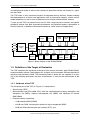
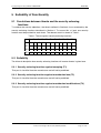
Security Target
SLE66CX320P
Infineon Technologies AG
Security and Chip Card IC
Version:
1.0.4_PUBLIC
Date:
08-08-2002
File:
Security Target_104_public.doc
Infineon Technologies AG, Security and Chip Card IC
Page 1 of 23
Security Target V1.0.4_PUBLIC: SLE66CX320P
08-08-2002
List of Contents
1 Product Description
1.1 Product overview
1.2 Definition of the Target of Evaluation
1.2.1 Hardware of the TOE
1.2.2 Firmware and software of the TOE
1.2.3 Interfaces of the TOE
1.3 Type of product use
4
4
5
5
6
7
7
2 TOE Environments
2.1 Development environment
2.2 Production environment
2.3 Operational environment
9
10
10
10
3 TOE Security Environment
3.1 Assets
3.2 Subjects
3.3 Security objectives
3.4 Threats
3.5 Additional requirements deriving from SigG/SigV
11
11
12
12
12
14
4 Security Enforcing Functions
4.1 SF1: Operating state checking
4.2 SF2: Data encryption with an on-chip key management and random number generation
4.3 SF3: Phase management and test mode lock-out
4.4 SF4: Protection against snooping
15
15
15
15
16
5 Suitability of Functionality
5.1 Correlations between threats and the security enforcing functions
5.2 Suitability
5.2.1 Security enforcing functions against snooping (T1)
5.2.2 Security enforcing functions against unauthorized use (T2)
5.2.3 Security enforcing functions against unauthorized modifications (T3)
17
17
17
17
17
17
6 Description of security mechanisms
6.1 M1: Operating state monitoring mechanisms
6.2 M2: Encryption mechanisms
6.3 M3: Phase management and test mode lockout mechanisms
6.4 M4: Anti-snooping mechanisms
6.5 Correlation between security functions / mechanisms
18
18
18
18
18
18
7 Evaluation Objective
7.1 Target evaluation level
7.2 Minimum strength of mechanisms
19
19
19
8 Annexes
8.1 List of abbreviations
8.2 List of documents supplied to customers as a manual
8.3 Sources
8.4 Glossary
20
20
21
21
21
List of Figures
Figure 1: Block diagram of the SLE66CX320P ...................................................................... 5
Infineon Technologies AG, Security and Chip Card IC
Page 2 of 23
Security Target V1.0.4_PUBLIC: SLE66CX320P
08-08-2002
List of Tables
Table 1: Threats against security enforcing functions .......................................................... 17
Infineon Technologies AG, Security and Chip Card IC
Page 3 of 23
Security Target V1.0.4_PUBLIC: SLE66CX320P
08-08-2002
1 Product Description
This Security Target relates to the delta evaluation of the SLE66CX320P / m1421b25.
1.1 Product overview
The Target of Evaluation (TOE), the SLE66CX320P chip, is a smart card IC (Security Controller) meeting the highest requirements in terms of performance and security. It is manufactured by Infineon Technologies AG in a 0.25 µm CMOS technology. The IC is intended to
be used in smart cards for particularly security-relevant applications. That is based on its
previous use as developing platform for smart card operating systems according to the lifecycle model [PP/9806].
The SLE66CX320P chip is a port of the SLE66CX160S architecture to a smaller production
technology and is implemented with the 0.25 µm technology. The changes in the application
software are therefore relative small and one can port existing applications very comfortable.
As a side effect of this porting the most components are unchanged. The documents related
to the ITSEC evaluation of the SLE66CX160S and SLECX160M can be used unchanged.
The IC, whose block diagram is shown in Figure 1, consists of a dedicated microprocessor
(CPU) with a MMU (Memory Management Unit), several different memories, security logic, a
timer and an interrupt-controlled I/O interface. A RNG (Random Number Generator) and a
checksum module (CRC module) are integrated on the chip.
The CPU is compatible with the SAB 8051 instruction set and is 6 times faster than the standard processor. It provides additional powerful instructions for smart card applications. The
memory comprises 256 bytes of internal RAM (IRAM), 2 KB of extended RAM (XRAM),
64 KB of user ROM, 8 KB of test ROM and 32 KB of EEPROM. It thus meets the requirements of the new generation of operating systems. The CPU accesses the memory via the
integrated Memory Encryption and Decryption unit (MED). The access rights of the application to the memories can be controlled with the memory management unit (MMU). Security,
sleep mode and interrupt logic as well as the RNG are specially designed for smart card applications. The sleep mode logic (clock stop mode per ISO/IEC 7816-3 (1997)) is used to
reduce the overall power consumption. The timer permits easy implementation of modern
communication protocols such as T=1 and all other time-critical operations. The uartcontrolled I/O interface allows the smart card and terminal to be operated in parallel. The
PLL unit allows to operate the SLE66CX320P with a multiplication factor over the external
clock signal. The RNG does not supply a pseudorandom number sequence, but instead produces genuine random numbers under all conditions. The checksum module allows simple
calculation of checksums per ISO 3309 (16 bit CRC).
Two modules for cryptographic operations are implemented on the TOE. The well known
ACE (Advanced Crypto Engine) for calculation of asymmetric algorithms like RSA. This
module is especially designed for chipcard application with respect to the security and power
consumption. The new module is the DDES which computes the complete DES algorithm
within a few clock cycles. That module is especially designed to counter attacks like DPA.
The software (firmware) required for operating the chip consists of routines for programming
the EEPROM from application programs and for online-testing of the RNG. These are stored
in a reserved user ROM area. In addition, the chip initialisation routine with security checks
Infineon Technologies AG, Security and Chip Card IC
Page 4 of 23
Security Target V1.0.4_PUBLIC: SLE66CX320P
08-08-2002
and identification mode as well as test routines for production testing are located in a separate test ROM.
The TOE offers a new, improved standard of integrated security features, thereby meeting
the requirements of all smart card applications such as information integrity, access control,
mobile telephone, as well as uses in electronic funds transfer and healthcare systems.
To sum up, the TOE is a powerful smart card IC with a large amount of memory and special
peripheral devices with both improved performance and optimised power consumption at
minimal chip size. It therefore constitutes the basis for future smart card applications.
Non Volatile Memory 32 KB
RNG
VCC
GND
CLK
RST
I/O
Security
Logic
CPU
with MED,
MMU
and IRAM
256B
Interrupt
Module
ROM
16 B
CRC
PROM
16 B
EEPROM
32736 B
TestROM
8 KB
XRAM
2 KB
Address and Data Bus
Timer
ACE
DDC
UserROM
64 KB
Figure 1: Block diagram of the SLE66CX320P
1.2 Definition of the Target of Evaluation
The TOE comprises the hardware of the smart card security controller, type SLE66CX320P,
manufactured by Infineon Technologies AG, and part of the associated firmware required for
operation and provided in ROM. The documents listed in Annex 8.2 are supplied as a manual. In the following description, the term “manufacturer” is short for the manufacturer of the
TOE.
1.2.1 Hardware of the TOE
The hardware part of the TOE (cf. Figure 1) is comprised of:
• Security logic (SEC)
• Microcontroller type ECO 2000 (CPU) with the subcomponents memory encryption and
decryption unit (MED), memory management unit (MMU) and 256 bytes of internal
RAM (IRAM)
• External memory comprising:
− 2 KB extended RAM (XRAM)
− 64 KB user ROM, including the routines for chip management (RMS)
− 8 KB test ROM containing the test routines (STS), and
Infineon Technologies AG, Security and Chip Card IC
Page 5 of 23
Security Target V1.0.4_PUBLIC: SLE66CX320P
08-08-2002
− a total of 32 KB nonvolatile memory (EEPROM). This is divided in three different protected parts. 16 bytes are functionally ROM for chip identification and security functions, another 16 bytes are PROM (only erasable), the remainder (32736 bytes) is
available as EEPROM program/data memory.
• Genuine random number generator (RNG)
• Checksum module (CRC)
• Interrupt module (INT)
• Timer (TIM)
• Address and data bus (BUS)
• Advanced Crypto Engine (ACE) for long integer modulo calculations, which are used in
asymetric algorithms like RSA
• DES accelerator (DDC), used for fast calculations of the DES algorithm.
1.2.2 Firmware and software of the TOE
The entire firmware of the IC consists of routines for EEPROM programming, RNG tamper
testing (Resource Management System, RMS) and test and initialization routines (Self Test
Software, STS). The RMS routines are stored in a reserved area of the normal user ROM,
whereas the STS routines are in the especially protected test ROM. The STS firmware is
divided into
− routines for the chip initialization after reset (STS Init Mode, STS-Init),
− routines setting up the normal operation mode (STS User Mode, STS-UM),
− routines used for chip identification (STS Chip Identification mode, STS-CI), and
− routines only used for the protected production testing (Test Mode, STS-TM).
The firmware part of the TOE, stored in the test ROM, is subdivided into:
•
STS-Init
•
STS-UM
•
STS-CI
•
STS-TM entry.
The STS-TM routines themselves are not part of the TOE, as the routines itself are not relevant for the security policy of the TOE (the production testing itself is of course evaluated).
The entry to this special test mode (STS-TM) is part of the security policy as it is a goal that
only the manufacturer is allowed to use the test routines. Therefore the entry to the STS-TM
is part of the TOE.
The RMS routines are not part of the TOE, as they are not part of the security policy itself.
But the use of the RMS routines is necessary to program the EEPROM. That is controlled by
hardware, which is part of the TOE.
Infineon Technologies AG, Security and Chip Card IC
Page 6 of 23
Security Target V1.0.4_PUBLIC: SLE66CX320P
08-08-2002
The operating system (OS) as well as application programs and data are not part of the
TOE. The operating system producer is supplied with the Databook [DataBook] as a manual.
This is containing descriptions of the RMS routines.
Attention is drawn to the fact that with the exception of the test ROM and the reserved ROM
areas for RMS and chip identification, the remaining memory areas are only part of the TOE
as hardware, in so far as the confidentiality of the stored information is ensured. The data
contents of these memories themselves are not part of the TOE.
The above demarcations of the TOE result in the interfaces described below.
1.2.3 Interfaces of the TOE
•
The physical interface of the TOE to the external environment is the entire surface of the
IC.
•
The electrical interface of the TOE to the external environment is constituted by the pads
of the chip, particularly the contacted RES, I/O, CLK lines and supply lines VCC and
GND.
•
The data-oriented I/O interface to the TOE is formed by the I/O pad.
•
The interface to the firmware is constituted by special registers used for hardware configuration and control (Special Function Registers, SFR).
•
The interface of the TOE to the operating system is constituted on the one hand by the
RMS routine calls and on the other by the instruction set of the TOE.
•
The interface of the TOE to the test routines is formed by the STS test routine call, i.e.
entry to test mode (STS-TM entry).
1.3 Type of product use
For using the TOE, a distinction must be drawn between two different cases.
The card manufacturer uses the TOE to implement the operating system and his specific
applications on it. He is responsible for integrating the TOE into a comprehensive security
system using the security features provided by the TOE. For this purpose the card manufacturer is supplied with extensive documentation for the TOE including RMS, as well as the
necessary development tools that will allow him to implement his applications and the operating system on the TOE. This includes not only programming tools, but also emulators and
consulting services. The card manufacturer integrates the TOE in the smart card and undertakes the initialisation and personalisation of the card which therefore no longer pertains
to the TOE.
The end user makes use of the TOE issued, personalised and initialised by the card manufacturer depending on the field of application, e.g. for
•
Cashless funds transfer applications
•
Applications in the telecommunications field (GSM, PCN, paging or broadcast services)
•
Pay-TV applications
•
Access control applications
•
Applications in the healthcare field (patient cards, health professional cards)
Infineon Technologies AG, Security and Chip Card IC
Page 7 of 23
Security Target V1.0.4_PUBLIC: SLE66CX320P
•
08-08-2002
or combinations of the above applications in the case of multi-application cards
The way the product is used varies markedly depending on the application, which is determined by the relevant software and therefore lies outside the TOE itself. The common features at TOE level are secure data holding and processing which guarantee confidentiality.
Infineon Technologies AG, Security and Chip Card IC
Page 8 of 23
Security Target V1.0.4_PUBLIC: SLE66CX320P
08-08-2002
2 TOE Environments
The TOE passes through several phases during its lifetime (cf. [PP/9806]). In the scope of
this evaluation are the phases 2 and 3 as defined in [PP/9806]. But the security enforcing
functions have the phase 7 from [PP/9806] in scope, so this phase will be in mind during the
evaluation. The life-cycle model results in the following environments:
•
Development
The development phase must be divided into hardware/firmware development and the
development of OS and application software, as the former are the responsibility of the
TOE manufacturer, but the latter are that of external software producers which are at the
same time users of the TOE. The TOE itself leaves the development phase if the photomasks are generated.
Manufacturer-related development is subdivided into:
−
Design and specification of the IC
−
Hardware design; this includes circuit development, layout development and creation
of the photomask information, all of which are computer-aided processes;
−
Firmware development
−
Supporting measures such as documentation and provision of the necessary information and software tools
•
Production
In this phase, chip fabrication takes place on the basis of the mask data and information
provided from OS development (which goes into user ROM programming) in the relevant
technology. This is followed by testing of the ICs produced as well as programming of
identification of the successfully tested chips. The production environment is left if the
TOE is in the user mode (after successful testing) and if the TOE is then delivered.
•
User environment
This phase consists of smart card production, personalization by the card issuer and actual use by the end user.
The life phases described above result in the subdivision of the TOE environments into development environment, production environment and operational environment which are explained in greater detail below.
In the development and production phase, the TOE cannot protect itself against the threats
present. Instead, organisational measures must be taken to counter these threats. A precise
description of the security measures in the development and production environment is provided in a separate document. As the OS producer does not constitute a threat, no countermeasures are taken against him. Only in the actual operational environment with the smart
card user can the TOE itself counter individual threats. As part of a finished smart card including the associated operating system, the TOE provides suitable technical measures
which must be used or supported by the installed OS to counter the threats. In the context of
this Security Target, only the technical measures provided by the TOE itself will be considered here.
Infineon Technologies AG, Security and Chip Card IC
Page 9 of 23
Security Target V1.0.4_PUBLIC: SLE66CX320P
08-08-2002
2.1 Development environment
Because of the subdivision of the development phase into TOE design development and
operating system development, it is also necessary to subdivide the development environment, namely into the development environment of the manufacturer and that of the OS
supplier. From the security specification point of view, OS development also represents the
first operational environment of the TOE. Here the user manual implicitly provides the OS
developers with initial information about the TOE design and the protection mechanisms
used. Consequently, the term “development environment” as used below is restricted to the
manufacturer's development environment. Existing threats are, for example, unauthorised
disclosure or unauthorised modification of specifications, design or protection functionality of
the TOE. These must be countered by appropriate safeguards which are documented separately.
2.2 Production environment
The production environment must faithfully create the actual hardware from the TOE design
documents and the OS development process. The threats within the production environment, such as theft of photomasks, wafers or finished chips, must be countered by suitable
measures. The necessary measures are described in a separate document.
2.3 Operational environment
The operational environment of the TOE is taken to be, on the one hand, the development
environment of the OS developer (see Section 2.1), and on the other the “actual” operational
environment with the user of the finished end product, the smart card. A secure development
environment of the OS producer akin to that of the manufacturer must be provided in order
to ensure the overall security of the TOE. Within the “final” operational environment, the
technical capability of the TOE to counter the threats described below in order to achieve the
security objectives takes effect. In the case of the end user, no requirements can of course
be placed on the operational environment.
Infineon Technologies AG, Security and Chip Card IC
Page 10 of 23
Security Target V1.0.4_PUBLIC: SLE66CX320P
08-08-2002
3 TOE Security Environment
3.1 Assets
This section lists the objects which must be protected against the threats mentioned in this
document. Unless otherwise specified, “hardware” refers to the TOE hardware. The objects
concerned are:
A1 Hardware design
This refers to the totality of the organizational and technical aspects beginning with the
IC specification and culminating in completed mask information. This includes in particular the basic concepts, implementation of the functionality through the building blocks
used (architecture), their electronic circuitry as well as implementation in layout
(IC design) under the constraints of the IC technology used. The hardware security
functionality implemented requires particular protection.
A2 Firmware (IC dedicated software)
The firmware comprising RMS and STS (see Section 1.2.2 for a more precise description) constitutes a sensitive object in its own right. But the RMS is embedded in the application software and is therefore protected the same way as the application software. It
is put together with the following asset A3. As only the hardware manufacturer has influence on the STS, this object is listed separately from object A3 “Operating system/application software and data” (the OS producer primarily having influence there).
A3 Operating system/application software and data (smartcard embedded software)
The operating system is influenced exclusively by its producer and is stored in the user
ROM. Appropriate implementation must prevent a potential attacker from gaining access
to information about protection mechanisms present by using the operating system.
User-specific data refers to all application-relevant information stored in the EEPROM
(programs and data).
Particularly sensitive items include the access rights, authentication information, data
protection mechanisms and crypto algorithms which are implemented in the OS and application software for protecting the user data, as well as the user data itself. With regard to using the TOE for applications subject to German signature law [SigG, SigV],
protecting the private signature key is of particular importance.
The RMS routines are part of asset A3 as they are logically embedded in the application
and as they are protected like the application.
A4 Test routines
These include the routines stored in the test ROM which are reserved for production
testing - these are at the same time part of the firmware and therefore a subset of A2 –
but as they are protected additionally with the entry to this mode (STS-TM entry), they
are listed separately.
A5 Manufacturer-specific data for chip identification
This is data stored in the reserved ROM area of the EEPROM and allocated by the
hardware manufacturer to chip ID (cf. Section 1.2.1).
A6 Manufacture-specific data for memory encryption
Infineon Technologies AG, Security and Chip Card IC
Page 11 of 23
Security Target V1.0.4_PUBLIC: SLE66CX320P
08-08-2002
This is data stored in the functional ROM area of the EEPROM and used for storing the
basic key for the MED (cf. Section 1.2.1).
3.2 Subjects
The following subjects are involved:
•
External users
These are people who could attack the finished TOE (hardware or firmware). For example,
the end user of the card must be seen as a potential attacker. Persons who pose a threat to
the TOE during development using the conditions of the development environment or of the
production line are therefore excluded.
•
Operating system producer
The operating system producer who produces the OS in a secure development environment
is not regarded as an attacker and does not constitute a threat.
3.3 Security objectives
The following security objectives may be identified for the TOE. Modifications must in turn be
understood in the sense of threat T3.
SO1 The hardware must be protected from snooping to obtain information about the security functionality.
SO2 The hardware must be protected from unauthorized modification of the security functionality.
SO3 The information stored in all the memories must be protected against unauthorized
access.
SO4 The information stored in all the memories must be protected against unauthorized
modification.
SO5
It must not be possible to execute the STS-TM test routines without authorization.
to SO3 and SO4) Protection against access/modification of the information in the EEPROM
must be supported by the OS (cf. Sections 5.2.1 and 6.2).
3.4 Threats
The threats listed below, against which the TOE must protect itself (class I from [PP/9806])
by suitable measures, may be assumed to be present. Actions initiated by the operating
system implemented in a secure development environment are not regarded as threats.
T1: Snooping
This type of threat concerns the risk of an attacker being able to read out information from
sensitive objects in an unauthorized manner.
T1.1: Disclosure of hardware design (A1)
An attacker might attempt to obtain information about the security functionality
of the hardware. This includes aspects of IC specification, IC design and
IC technology.
Infineon Technologies AG, Security and Chip Card IC
Page 12 of 23
Security Target V1.0.4_PUBLIC: SLE66CX320P
08-08-2002
T1.2: Unauthorized readout of the firmware (A2)
An attacker might attempt to read out the firmware and thus obtain information
about implemented protection mechanisms.
T1.3: Unauthorized readout of operating system/application software and data (A3)
An attacker might attempt to read out the OS, application software or data.
T1.4: Unauthorized readout of manufacturer-specific data for memory encryption (A6)
An attacker might attempt to read out the memory area containing the basic
key for MED encryption.
T2:
Unauthorized use
This type of threats concerns the risk of an attacker using the TOE in an unauthorized manner.
T2.1: Unauthorized execution of test routines (A4).
An attacker might attempt to illicitly execute the STS-TM routines reserved for
the manufacturer, i.e. initiating STS-TM entry
T3:
Unauthorized modifications
This type of threat concerns the risk of an attacker modifying the TOE in such a way that
security functionalities of the TOE are bypassed or changed. The modifications listed should
be understood as representing deliberate actions designed to enable unauthorized use of
the TOE or of the software or data stored in the TOE. Modifications which would destroy the
TOE or render it unusable are not included.
T3.1: Unauthorized modification of the hardware (A1)
An attacker might attempt to modify the hardware or the implemented hardware
protection mechanisms.
T3.2: Unauthorized modification of the firmware (A2)
An attacker might attempt to modify the firmware (program code and execution)
including the protection mechanisms contained therein.
T3.3: Unauthorized modification of operating system/application software and data (A3)
An attacker might attempt to modify the OS (program code and execution), application programs or data.
T3.4: Unauthorized modification of the test routines (A4)
An attacker might attempt to modify the routines of the STS-TM (program code
and execution) or entry to this mode (STS-TM entry).
T3.5: Unauthorized modification of manufacture-specific data for chip identification (A5)
An attacker might attempt to modify the manufacturer-specific data of the individual chip ID.
T3.6: Unauthorized modification of the manufacture-specific data for memory encryption
(A6)
An attacker might attempt to modify the data constituting the basic key for MED
encryption.
Infineon Technologies AG, Security and Chip Card IC
Page 13 of 23
Security Target V1.0.4_PUBLIC: SLE66CX320P
08-08-2002
3.5 Additional requirements deriving from SigG/SigV
In accordance with SigG, the technical components used for generating and storing signature keys and for generating signatures must provide protection against unauthorized use of
private signature keys (requirement e.g. also placed on signature smart cards).
In accordance with SigV, the technical component required for generating signature keys
must be designed in such a way that a key has a probability bordering on certainty of being
unique, the secret key is kept secret and cannot be duplicated. Security modifications to the
technical components must be recognizable to the user.
In accordance with SigV, the secret signature key must not be divulged during use and must
not be able to be used until identification of the user through possession and knowledge,
whereby biometric features can additionally be used. Identification data (e.g. PIN) should
only be stored on the component with the secret signature key and should be kept secret.
Following from these requirements specifically for the TOE considered here in terms of the
above security objectives:
•
Readout of the secret keys and identification data is always illegal and must be prevented (also relates to the use of secondary effects such as power consumption, radiated emission and timing of the smart card)
•
If the smart card is also used in future for key generation, suitable random number generation methods (physically based) must be used as in §17 (2) SigV.
•
The smart card must be capable of meeting the requirements in terms of algorithms and
parameters (incl. key length) (e.g. execution of computing operations with the required
key lengths).
Infineon Technologies AG, Security and Chip Card IC
Page 14 of 23
Security Target V1.0.4_PUBLIC: SLE66CX320P
08-08-2002
4 Security Enforcing Functions
In order to be able to counter the threats, the SLE66CX320P is equipped with the following
security enforcing functions:
SF1: Operating state checking
SF2: Data encryption with an on-chip key management and random number generation
SF3: Phase management with test mode lock-out
SF4: Protection against snooping
4.1 SF1: Operating state checking
Correct function of the SLE66CX320P is only given in the specified range. To prevent an
attack exploiting that circumstances it is necessary to detect if the specified range is left.
All operating signals are filtered to prevent malfunction
In addition the operating state is monitored with sensors for the operating voltage, clock signal frequency. The TOE falls into the defined secure state in case of a specified range violation1.
4.2 SF2: Data encryption with an on-chip key management and
random number generation
The readout of data can be controlled with the use of encryption. Only the key owner has the
possibility to read out data. An attacker can not use the data he has espionaged, because he
must break the encryption.
The memory contents of the SLE66CX320P are encrypted on chip to protect against data
analysis on stored data as well as on internally transmitted data. To prevent interpretation of
leaked information randomness is inserted in the information.
An interpretation of the leaked data is not possible as all the data is encrypted.
Random data is essential for cryptography as well as for physical security mechanisms. The
SLE66CX320P is equipped with a true random generator based on physical probabilistic
controlled effects. The random data can be used from the user software as well as from the
security enforcing functions.
4.3 SF3: Phase management and test mode lock-out
The life cycle of the TOE is split-up in several phases. Chip development and production
(phase 2, 3, 4) and final use (phase 4-7) is a rough split-up from TOE point of view. These
phases are implemented in the SLE66CX320P as test mode (phase 2, 3, 4) and user mode
(phase 1, 4-7). In addition a chip identification mode exists which is active in all phases.
1
The operating state checking SEF1 can only work when the TOE is running and can not prevent reverse engineering.
Infineon Technologies AG, Security and Chip Card IC
Page 15 of 23
Security Target V1.0.4_PUBLIC: SLE66CX320P
08-08-2002
During start-up of the SLE66CX320P the decision for the user mode or the test mode is
taken dependent on several phase identifiers (phase management). If test mode is the active
phase the SLE66CX320P requests authentication before any action (test mode lock-out).
If the chip identification mode is requested the chip identification data (A5) is reported.
The phase management is used to provide the separation between the security enforcing
functions and the user software.
4.4 SF4: Protection against snooping
Several mechanisms protect the SLE66CX320P against snooping the design or the user
data during operation and even if it is out of operation (power down).
There are topological design measures for disguise, such as the use of the top metal layer
with active signals for protecting critical data. The entire design is kept in a non standard way
to prevent attacks using standard analysis methods. A Smartcard dedicated CPU with a non
public bus protocol is used which makes analysis complicated.
Infineon Technologies AG, Security and Chip Card IC
Page 16 of 23
Security Target V1.0.4_PUBLIC: SLE66CX320P
08-08-2002
5 Suitability of Functionality
5.1 Correlations between threats and the security enforcing
functions
To achieve the security objectives, the threats defined in Section 3.4 are countered by the
security enforcing functions described in Section 4. To ensure this, at least one security
function must be provided for each threat. The relevant matrix is shown in Table 1.
Table 1: Threats against security enforcing functions
T1.1 T1.2 T1.3 T1.4 T2.1 T3.1 T3.2 T3.3 T3.4 T3.5 T3.6
SF1
X
X
X
SF2
X
X
X
SF3
X
X
X
X
X
X
SF4
X
X
X
X
X
X
X
X
X
X
X
X
X
X
X
X
X
X
X
X
5.2 Suitability
The informal description how security enforcing functions will counter threats is given here.
5.2.1 Security enforcing functions against snooping (T1)
That part is classified from the manufacturer and will not be published.
5.2.2 Security enforcing functions against unauthorized use (T2)
That part is classified from the manufacturer and will not be published.
5.2.3 Security enforcing functions against unauthorized modifications (T3)
That part is classified from the manufacturer and will not be published.
Infineon Technologies AG, Security and Chip Card IC
Page 17 of 23
Security Target V1.0.4_PUBLIC: SLE66CX320P
08-08-2002
6 Description of security mechanisms
The security mechanisms can be divided into four different classes and are assigned to the
security enforcing functions as explained in Section 4.
The security mechanisms are described more in a implementation manner than the more
abstract security functions.
6.1 M1:
Operating state monitoring mechanisms
That part is classified from the manufacturer and will not be published.
6.2 M2:
Encryption mechanisms
That part is classified from the manufacturer and will not be published.
6.3 M3:
Phase management and test mode lockout mechanisms
That part is classified from the manufacturer and will not be published.
6.4 M4:
Anti-snooping mechanisms
That part is classified from the manufacturer and will not be published.
6.5 Correlation between security functions / mechanisms
That part is classified from the manufacturer and will not be published.
Infineon Technologies AG, Security and Chip Card IC
Page 18 of 23
Security Target V1.0.4_PUBLIC: SLE66CX320P
08-08-2002
7 Evaluation Objective
7.1 Target evaluation level
ITSEC evaluation level E4 is specified for the TOE in respect of correctness of implementation.
7.2 Minimum strength of mechanisms
The minimum strength required of all mechanisms used is high.
Infineon Technologies AG, Security and Chip Card IC
Page 19 of 23
Security Target V1.0.4_PUBLIC: SLE66CX320P
08-08-2002
8 Annexes
8.1 List of abbreviations
CI
Chip Identification mode (STS-CI)
CIM
Chip Identification Mode (STS-CI), same as CI
CPU
Central Processing Unit
CRC
Cyclic Redundancy Check
DPA
Differential Power Analysis
EEPROM
Electrically Erasable and Programmable Read Only Memory
HW
Hardware
IC
Integrated Circuit
ID
Identification
I/O
Input/Output
IRAM
Internal Random Access Memory
ITSEC
Information Technology Security Evaluation Criteria
M
Mechanism
MED
Memory Encryption and Decryption
MMU
Memory Management Unit
MOVC
MOVe Code
O
Object
OS
Operating system
PLL
Phase Locked Loop
PROM
Programmable Read Only Memory
RAM
Random Access Memory
RMS
Resource Management System
RNG
Random Number Generator
ROM
Read Only Memory
S
Subject
SF
Security function
SFR
Special Function Register
SigG
Signature law, see [SigG]
SigV
Signature regulation, see [SigV]
STS
Self Test Software
SW
Software
SO
Security objective
T
Threat
TM
Test Mode (STS)
TOE
Target of Evaluation
Infineon Technologies AG, Security and Chip Card IC
Page 20 of 23
Security Target V1.0.4_PUBLIC: SLE66CX320P
UM
User Mode (STS)
XRAM
eXtended Random Access Memory
08-08-2002
8.2 List of documents supplied to customers as a manual
[MaskTransfer]
SLE 66CX320P Transfer of a ROM Mask from SLE 66CxxS to SLE ; Version 11.99
CX320P
[AppRNG]
Application Note, SLE66CxxxP, Testing the RNG, 05.00
[AppDES]
Application Note, SLE66CxxxP, DES / EC2 Accelerator, 05.00
[AppMED]
Application Note, SLE66CxxxP, Memory Encryption Decryption, 05.00
[AppShield]
Application Note, SLE66CxxxP, Using the active shield security feature, 05.00
[Status]
Status report, 06.00
[DataBook]
Data Book, SLE66CxxxP
12.00
8.3 Sources
[ITSEC91]
IT Security Evaluation Criteria (ITSEC), current form of harmonized criteria
; Version
1.2
06.91
[PP/9806]
09.98
Protection Profile Smart Card Integrated Circuit
; Version
2.0
[SigG] German Digital Signature Law (Signaturgesetz – SigG) of 22.07.1997 (BGB1. I S.
1870, 1872), promulgated as Article 3 of the 'Law governing the regulatory framework for
information and communication services (In-formation and Communication Services Law –
IuKDG)‘.
[SigV]
German Digital Signature Regulation (Signaturverordnung – SigV) of
22.10.1997 (BGB1. I S. 2498).
8.4 Glossary
Application Program/Data
Software which implements the actual TOE functionality
provided for the user or the data required for that purpose
Threat
Action or event that might prejudice security
Operating System
Software which implements the basic TOE actions necessary for operation
Central Processing Unit
Logic circuitry for digital information processing
Chip → Integrated Circuit
Infineon Technologies AG, Security and Chip Card IC
Page 21 of 23
Security Target V1.0.4_PUBLIC: SLE66CX320P
08-08-2002
Chip Identification Mode
Operational status phase of the TOE, in which actions for
identifying the individual chip take place
Smart Card
Plastic card in credit card format with built-in chip
Controller
IC with integrated memory, CPU and peripheral devices
Cyclic Redundancy Check
Process for calculating checksums for error detection
Electrically Erasable and Programmable Read Only Memory (EEPROM)
Nonvolatile memory permitting electrical read and write
operations
End User
Person in contact with a TOE who makes use of its operational capability
Firmware
Part of the software implemented as hardware
Hardware
Physically present part of a functional system (item)
Integrated Circuit
Component comprising several electronic circuits implemented in a highly miniaturized device using semiconductor technology
Internal Random Access Memory
RAM integrated in the CPU
Mechanism
Logic or algorithm which implements a specific security
function in hardware or software
Memory Encryption and Decryption
Method of encoding/decoding data transfer between CPU
and memory
Microcontroller → Controller
Microprocessor → CPU
Move Code
Instruction in the CPU’s instruction set for transferring program memory contents to an internal register
Object
Physical or non-physical part of a system which contains
information and is acted upon by subjects
Programmable Read Only Memory
Nonvolatile memory which can be written once and then
only permits read operations
Infineon Technologies AG, Security and Chip Card IC
Page 22 of 23
Security Target V1.0.4_PUBLIC: SLE66CX320P
08-08-2002
Random Access Memory
Volatile memory which permits write and read operations
Random Number Generator
Hardware part for generating random numbers
Read Only Memory
Nonvolatile memory which permits read operations only
Resource Management System
Part of the firmware containing EEPROM programming
routines
Self Test Software
Part of the firmware with routines for controlling the operating state and testing the TOE hardware
Security Function
Part(s) of the TOE used to implement part(s) of the security objectives
Security Target
Description of the intended state for countering threats
Software
Information (non-physical part of the system) which is required to implement functionality in conjunction with the
hardware (program)
Memory
Hardware part containing digital information (binary data)
Subject
Entity, generally in the form of a person, who performs actions
Target of Evaluation
Product or system which is being subjected to an evaluation
Test Mode
Operational status phase of the TOE in which actions to
test the TOE hardware take place
User Mode
Operational status phase of the TOE in which actions intended for the user take place
Infineon Technologies AG, Security and Chip Card IC
Page 23 of 23