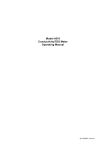
1
$',167580(176
$'Multifunction Tester
User Manual
Multifunction Tester User Manual
Multifunction Tester User Manual
Contents
Page
1-Safety Considerations ......................................................................... 4
1. 1.1-International Symbols .................................................................... 4
1. 1.2-Terminology................................................................................. 4
1. 1.3-Warnings ..................................................................................... 4
1. 1.4-Caution ........................................................................................ 5
1. 1.5-Declaration of Conformity............................................................... 5
1. 1.6-Error Codes .................................................................................. 5
2-Specification ...................................................................................... 5
3-General Specification .......................................................................... 8
4-Instrument Overview........................................................................... 8
4. 4.1-Front View.................................................................................... 8
4. 4.2-Connector Panel ............................................................................9
4. 4.3-Battery & Fuse .............................................................................. 9
4. 4.4-Understanding the Display...............................................................10
5-How to Use the Tester......................................................................... 13
4. 5.1-Impor tant Symbols and Messages during the measurement .................13
4. 5.2-Using the LOOP/PFC Function ........................................................ 15
6-Using the Insulation Function ................................................................ 27
4. 6.1-Insulation Function/Menu Operation ................................................. 27
4. 6.2-Insulation Resistance Display/Switch and Terminal Settings ................ 28
4. 6.3-Using the RE Function .................................................................... 28
4. 6.4-Ear th Resistance Display/Switch and Terminal Settings ...................... 29
4. 6.5-To Measure Ear th Resistance .......................................................... 29
4. 6.6-RE Function Menu Operation ........................................................... 29
4. 6.7-Using the LOW OHM Function .......................................................... 29
4. 6.8-LOW OHM Function Menu Operation ................................................. 30
7-Menu ................................................................................................ 31
8-System Settings ................................................................................. 31
4. 8.1-Languages ................................................................................... 31
4. 8.2-Date/Time .................................................................................... 32
4. 8.3-TV............................................................................................... 32
4. 8.4-Memory....................................................................................... 32
4. 8.5-Auto Screen-off.............................................................................33
4. 8.6-Auto Power-off.............................................................................. 33
4. 8.7-System Default Settings ..................................................................33
4. 8.8-System Upgrade ............................................................................34
9-Run Settings ...................................................................................... 34
4. 9.1-Bluetooth ..................................................................................... 34
4. 9.2-Data Record ................................................................................. 35
4. 9.3-Datalog ....................................................................................... 35
10-Data Record ..................................................................................... 35
10- 10.1-Delete Files .............................................................................. 36
10- 10.2-Data Record Preview.................................................................. 36
10- 10.3-Menu ....................................................................................... 37
10- 10.4- Drawing ................................................................................. 38
10- 10.5-Datalog Color........................................................................... 39
3
Multifunction Tester User Manual
Warning!
You must read and completely understand the Safety Considerations part of this manual before using the
instrument.
1-Safety Considerations
This manual contains instructions regarding the safe use and the proper functioning of the instrument. If not
complied with, the user could be exposed to danger and the instrument to possible damage.
1.1-International Symbols
WARNING!
CAUTION! Voltage present
Earth
Double Insulation (Class II insulation)
Fuse
>550V
Prohibited to use for the Electrical System which uses the voltage above 550V
Conformity to European Standards
1.2-Terminology
The term WARNING as used in this manual defines a condition or a procedure which could lead to a serious
injury or accident. The term CAUTION defines a condition or action which could lead to the instrument being
rendered defective during the testing process.
1.3-Warnings
• Make sure to read and fully understand the instruction contained within this manual prior to use.
• This instrument is not intrinsically safe therefore do not use the instrument in hazardous environments.
• In order to prevent fire and/or electrical shock, do not use the instrument in wet, damp or highly humid
• environments.
• Prior to use, check if the instrument functions correctly. If any symptoms/symbols of malfunction or abnormalities
• are indicated, do not use and inform MTi Instruments.
• Users who could be exposed to voltages in excess of the extra low band (50V ac or 120V dc) should be
• competent and be aware of the requirements of GS 38 regarding the use of the instrument and the associated
• leads and probes etc.
• Make sure your fingers holding the test probes are positioned behind the safety lines of the test probes.
• DO NOT OPEN THE INSTRUMENT.
• If the internal fuse (protective device) operates, replace with a device of the same type and rating. If it operates
• again seek professional advice. DO NOT REPLACE FUSE AND TRY AGAIN.
• When carrying out the “dead tests” ensure prior to connection of the instrument leads the circuit under test
• has been confirmed “dead” and secured in the OFF position using appropriate methods.
• Battery condition is indicated by a beep. Check and replace if necessary.
• Do not test an electrical circuit or systems where the voltage is in excess of 550V.
• Ensure at all times the leads are in compliance with GS 38 (as supplied) and not damaged.
4
Multifunction Tester User Manual
1.4-Caution
Do not change functions on the test instrument with the test leads in place, i.e. changing from a “dead test”
to a test where the supply is required could damage the instrument.
1.5-Declaration of Conformity
This instrument has been tested according to the below regulations:
EN 61326: Electrical equipment for measurement, control and laboratory use.
EN 61010-1: Safety requirements for electrical equipment for measurement, control and laboratory use
–Part 1: General requirements.
BS EN61557: Electrical safety in low voltage distribution systems up to 1000V a.c. and 1500V d.c.
Equipment for testing, measuring or monitoring of protective measures.
• Part 1 General requirements
• Part 2 Insulation resistance
• Part 3 Loop resistance
• Part 4 Resistance of earth connection and equipotential bonding
• Part 6 Residual current devices (RCDs) in TT and TN systems
• Part 7 Phase sequence
• Part 10 Combined measuring equipment
1.6-Error Codes
Various error conditions are detected by the tester and are indicated with the icon, “Err”, and an error
number on the primary display. See Table 1. These error conditions disable testing and, if necessary, stop
a running test.
Table 1. Error Codes
Error Condition Code Code
Solution
1
Fault Voltage
Over Temp
2
Excessive Noise
3
Excessive Probe
Resistance
4
Self Test Fails
5
Solution
Check the installation, in particular, the voltage
between N and PE.
Wait while the tester cools down.
Switch off all appliances (Loop, RCD measurements)
and move the earth stakes (earth measurement).
Put the stakes deeper into the soil. Tamp down the
soil directly around the stakes. Pour water around
the stakes but not at the earth ground under test.
Return the tester to a Service Center.
2-Specification
LOOP Resistance
L- PE (Hi-Amp)
Range(Ω)
0.23~9.99
10.0~99.9
100~999
Resolution(Ω)
0.01
0.1
1
Accuracy
±(4% of reading+6digits)
Measuring Current: 8.0 A~25.0 A
Range of the Voltage Used: 195V a.c. – 260V a.c. (50,60Hz)
5
Multifunction Tester User Manual
Notes
[1] Valid for resistance of neutral circuit <20Ω and up to a system phase angle of 30°. Test leads must be
[1] zeroed before testing.
[2] Valid for mains voltage >200V.
L- PE (No Trip)
Range(Ω)
0.23~9.99
10.0~99.9
100~999
Resolution(Ω)
0.01
0.1
1
Accuracy
±(5% of reading+6 digits)
Measuring Current: < 15mA
Range of the Voltage Used: 195V a.c – 260V a.c (50,60Hz)(50,60Hz)
Notes
[1] Valid for resistance of neutral circuit <20Ω and up to a system phase angle of 30°. Test leads must be
[1] zeroed before testing.
[2] Valid for mains voltage >200V.
LINE Resistance
L- N
Range(Ω)
0.23 – 9.99
10.0 – 99.9
100 – 999
Resolution(Ω)
0.01
0.1
1
Accuracy
±(4% of reading+4digits)
Measuring Current: 4.0 A
Range of the Voltage Used: 195V a.c. – 260V a.c. (50,60Hz)
Notes
[1] Valid for resistance of neutral circuit <20Ω and up to a system phase angle of 30°. Test leads must be
[1] zeroed before testing.
[2] Valid for mains voltage >200V.
RCD (BSEN 61557-6)
Rcd Rating (I_n): 10mA, 30mA, 100mA, 300mA, 500mA, 650mA and 1A.
Test current: x1/2, x1, x2 and x5
Accuracy at applied test current
Current Multiplier Trip Time Accuracy
±(1% of reading+1ms)
x1/2
±(1% of reading+1ms)
x1
±(1% of reading+1ms)
x2
±(1% of reading+1ms)
X5
Form of the Test Current: Sine wave form (ac), Pulse wave form (dc)
RCD Form: General (G - non-delayed), Selective (S - time-delayed)
Initial Polarity of the Test Current: 0°, 180°.
Voltage Range: 195V a.c. - 260V a.c. (50Hz,60Hz)
6
Multifunction Tester User Manual
Accuracy of the Current of the RCD: ± (5% of reading + 1digits)
Resolution of the RCD Timing: 0.1ms
Voltage and Frequency
Measurement Range Resolution(V)
(V)/AC-DC
80~500
1
Accuracy
Measurement Range Resolution(Hz)
(Hz)
45~65
1
Accuracy
Insulation
Terminal Voltage
Range
Resolution
0.001Ω
0.01Ω
0.1Ω
1Ω
Earth Resistance
Range
Resolution
0.00~99.99Ω 0.01Ω
100.0~999.9Ω 0.1Ω
1000~2000Ω 1Ω
±2Hz
Resolution Accuracy
125V(0%~+10%) 0.125~4.000 MΩ
4.001~40.00 MΩ
40.01~400.0 MΩ
400.1~1000 MΩ
250V(0%~+10%) 0.250~4.000 MΩ
4.001~40.00 MΩ
40.01~400.0 MΩ
400.1~1000 MΩ
500V(0%~+10%) 0.500~4.000 MΩ
4.001~40.00 MΩ
40.01~400.0 MΩ
400.1~1000 MΩ
1000V(0%~+10%) 1.000~4.000 MΩ
4.001~40.00 MΩ
40.01~400.0 MΩ
400.1~1000 MΩ
Low Ohm
Range
0.000~2.000Ω
2.00~20.00Ω
20.0~200.0Ω
200~2000Ω
±(2% of reading +2digits)
0.001MΩ
0.01MΩ
0.1MΩ
1MΩ
0.001MΩ
0.01MΩ
0.1MΩ
1MΩ
0.001MΩ
0.01MΩ
0.1MΩ
1MΩ
0.001MΩ
0.01MΩ
0.1MΩ
1MΩ
Test Current
Short circuit
current
±(3%+10) 1mA @load125kΩ ≤1mA
±(2%+10)
±(4%+5)
±(5%+5)
±(3%+10) 1mA @load250kΩ ≤1mA
±(2%+10)
±(3%+2)
±(3%+2)
±(3%+10) 1mA @load500kΩ ≤1mA
±(2%+10)
±(3%+2)
±(4%+5)
±(3%+10) 1mA @load1MΩ ≤1mA
±(2%+10)
±(3%+2)
±(4%+5)
Accuracy
Max. Open Circuit Voltage Overload Protection
±(1.5%+30) 5.0V±1VDC
250Vrms
±(1.5%+3)
±(1.5%+5)
Accuracy
±(2%+30d)
±(2%+6d)
7
Multifunction Tester User Manual
3-General Specification
Power Source
Battery Life
CAT Rating
Protection Classification
Protection Rating
LCD Screen Type
Pixels
Operating Temp
Relative Humidity
Storing Temp
Operating Altitude
Protective device
Dimensions
Weight
8 x 1.5V AA Size Alkaline batteries
or 8 x 1.2V AA Size rechargeable Ni-MH batteries
Average of 15hours
CAT III 600V
Double Insulation
I
3.5”TFT
320x240
0°C~ 45°C
95% 10°C~ 30°C: Non-condensing
75% 30°C~ 40°C
-10°C~ 60°C
2000m
500mA Fast response BS 88 Fuse
24.2cm(L) x 10.5cm(W) x 14.5cm(H)
1.56kg
4-Instrument Overview
4.1-Front View
1-Starts the selected test. The T key is surrounded by a “touch pad”. The touch pad measures the potential
1- between the operator and the tester’s PE terminal. If you exceed a 100 V threshold, the D symbol above
1- the touch pad is illuminated.
2-Warning lamp
3-320X(RGB)X240 color active matrix
4-Press and hold Turns the tester on and off. Short Press return the latest status.
5-Function selector switch.
6-Navigation keys:
6-Enter, Up, Down, Left/Save, Right
7-Selects the sub-menus from the Test Mode selected by the rotary switch:
7-F1, F2, F3, F4
8-Accesses help menus and delete files .
1
5
6
2
8
7
3
8
Multifunction Tester User Manual
4.2-Connector Panel
1-Input Terminal to operate the switched probe
2-L - Line Input
3-PE - Protective Earth Input
4-N - Neutral Input
5-Input Terminal to operate the switched probe
6-TV OUT
7-System Reset
8-USB Connector
9-Power Supply Socket
2
1
3
4
PE
L
5
N
L1
L2
L3
VΩ MΩ
CAT III 600V
RESET
TV OUT
15V DC
1.0A
9
6 7 8
4.3-Battery & Fuse
1-Fuse 5A 600V
2-Fuse 5A 600V
3-Fuse 500mA 600V
4-Battery cells (size AA).
1
2
3
0V
mA 60
F500
0≥
A H 60
≥50KA
50KA
F5
F5A H
600V
≥50KA
4
9
Multifunction Tester User Manual
4.4-Understanding the Display
5
28
12
13
11 10 9 8 6
1
27
2
26
7
14
15
16
3
17
18
19
20
4
25 24 23 22 21
No. Annunctator
Function
RCD
1
Value
TA
RCD TIME
T
RCD TIME
N
RCD TRIP
Loop/PFC
V/Phase
Continuity
10
L-PE
L-L
L-N
L-PE
0.5Ω
1.0Ω
2.0Ω
5.0Ω
AUTO
X1/2
X1
X2
X5
RAMP
Multifunction Tester User Manual
No. Annunctator
Function
1
Continuity
Terminal Voltage
2
Trip Current
Current
Beeper
3
10.0Ω
20.0Ω
50.0Ω
50.0Ω
125V
250V
500V
1000V
30mA
100mA
300mA
500mA
650mA
1000mA
10mA
NO Trip
Hi Amp
OFF
ON
Type of RCD
G
S
G
S
Lock
4
0°/180°
ZERO
Reference
5
OFF
ON
0°
180°
0
0.125MΩ
0.25MΩ
0.5MΩ
1MΩ
2MΩ
5MΩ
10MΩ
20MΩ
50MΩ
100MΩ
200MΩ
Date Time
11
Multifunction Tester User Manual
Meaning
Low battery icon. See
No. Annunctator
6
:Indicates the battery status.
:100%
:80%
:50%
:20%
:Low Battery
7
8
9
10
11
12
13
14
15
16
17
18
19
20
21
for additional information on batteries and power management.
Beeper
Lock
Hold
Datalog
Bluetooth
Appears when the instrument is overheated.
Display 30 seconds (time-delayed)
Being tested
Primary display and measurement units.
30S
888.8
Ω
Primary display and measurement units.
888.8
U F:
U L:
L
PE
L
PE
N
L
PE
N
L1
L2
L3
L
230
PE
N
1
Fault voltage. Measures neutral to earth.
Indicates the preset falut voltage limit.
Arrows above or below the terminal indicator symbol indicate
reversed polarity. Check the connection or check the wiring to
correct.
N
231
L
230
PE
1
N
231
26
N-PE Value
L-N Value
L-PE Value
Prospective Earth Fault Current.
Calculated from voltage and loop impedance which is measured
line to protective earth.
Prospective Short Circuit. Calculated from measured voltage
and impedance when reading line to neutral.
Being tested
27
28
High Voltage Warning
Warning
22
23
24
25
N-PE
L-N
L-PE
PFC
PSC
12
Multifunction Tester User Manual
5-How to Use the Tester
5.1-Important Symbols and Messages during the measurement
1
5
2
3
4 2
Figure 1 Screen
5.1Description
5.11-Battery status
5.12-Displayed measured value
5.13-The measurement unit of the measured value
5.14-The indication of the correct input terminal connection
5.15-Displayed menu
5.1.1-Displayed icons (symbols) and messages in VOLTAGE function
:Indicates the correct input terminal connectivity . The user should connect the test leads
to the appropriate terminals.
:Indicates L connection is connected on the N input terminal and vice-versa
:Indicates no connection on the PE input terminal
If the wiring condition is other than normal, the Tester is limited on its measurements that can be performed.
Notes:
• Will not detect two hot wires in a circuit.
• Will not detect a combination of defects.
• Will not detect reversal of grounded and grounding conductors.
:Indicates the battery status.
:100%
:80%
:50%
:20%
:Low Battery
13
Multifunction Tester User Manual
5.1.2-Displayed icons (symbols) and messages in LOOP/PFC function
:Indicates the correct input terminal connectivity . The user should connect the test leads
to the appropriate terminals.
:Indicates L connection is connected on the N input terminal and vice-versa
:Indicates no connection on the PE input terminal
If the wiring condition is other than normal, the Tester is limited on its measurements that can be performed.
Notes:
• Will not detect two hot wires in a circuit.
• Will not detect a combination of defects.
• Will not detect reversal of grounded and grounding conductors.
:Indicates the battery status.
:100%
:80%
:50%
:20%
:Low Battery
:Indicates high temperature and therefore cannot make any measurements
Message:
Measuring : Function in use - measurement being carried out
RCD Trip: During the measurement, the RCD has tripped therefore no test result obtained
-Noise-: Appears during the No Trip Loop Measurement, and indicates that the displayed value may not be
-Noise-: accurate due to “mains” interference - test to be repeated
5.1.3-Displayed icons (symbols) and messages in RCD function
: Indicates the correct input terminal connectivity . The user should connect the test leads
to the appropriate terminals.
: Indicates L connection is connected on the N input terminal and vice-versa
: Indicates no connection on the PE input terminal
If the wiring condition is other than normal, the Tester is limited on its measurements that can be performed.
Notes:
• Will not detect two hot wires in a circuit.
• Will not detect a combination of defects.
• Will not detect reversal of grounded and grounding conductors.
: Indicates the battery status.
: 100%
: 80%
: 50%
: 20%
14
Multifunction Tester User Manual
: Low Battery
: Indicates high temperature and therefore cannot make any measurements
Message:
Half: Appears during the auto test when rcd has operated on the x ½ test
Half Trip: Appears during the manual test when rcd has operated on the x ½ test
UL OVER: Appears when UF voltage exceeds the previously set UL voltage. (UL voltage can be set to 25V
UL OVER: or 50V) The user must check the impedance between L-PE
5.1.4-Displayed icons (symbols) and messages when using the LOW OHM and CONTINUITY functions
Symbol:
: Indicates correct input terminal connectivity. The user should connectthe test leads to
: the appropriate terminals indicated by color coding.
: Low Battery (The icon will be flashing along with the beep sound).
: The resistance of the test leads are included in the test measurement
: The resistance of the test leads are not included in the test measurement
5.1.5-Displayed icons (symbols) and messages when using the RE functions
: Indicates correct input terminal connectivity. The user should connect the test leads to
: the appropriate terminals indicated by color coding.
: Low Battery (The icon will be flashing along with the beep sound).
: The resistance of the test leads are included in the test measurement
: The resistance of the test leads are not included in the test measurement
5.1.6-Displayed icons(symbols) and messages in INSULATION function
: Indicates correct input terminal connectivity. The user should connect the test leads to
: the appropriate terminals indicated by color coding.
: Low Battery (The icon will be flashing along with the beep sound).
: Indicates high voltage (125V, 250V,500V or 1000V) at probe terminals, Use caution
5.2-Using the LOOP/PFC Function
1-Before you do a loop impedance test, use the zero adapter to zero the test leads or the mains cord. Press
annunciator appears. The tester measures
1-and hold F4 button for more than two seconds until the
1-the lead resistance, stores the reading in memory, and subtracts it from readings. The resistance value is
1-saved even when the power is turned off so it is unnecessary to repeat the operation each time you use the
1-tester with the same test leads or mains cord.
Note: Be sure the batteries are in good charge condition before you zero the test leads.
2-You can select UL Voltage by Pressing and hold F3 button for more than two seconds (25V or 50V).
15
Multifunction Tester User Manual
5.2.1-Using the No Trip LOOP Measurement to be selected where the circuit is protected by an RCD whose
rating is 30mA or above
1-Turn the rotary switch to the LOOP/PFC position
2-Connect the test leads as Figure Figure 4
3-If voltage of the L- PE on the lower left appears, the
1-unit is ready to TEST
4-Press the TEST button when ready
5-If NOISE appears during the No Trip Loop
3-Measurement, the displayed value may not be
3-accurate due to “mains” interference and the
3-test should be repeated
Ω
A
Figure 3-No Trip LOOP
When carrying out the test from a 13A socket
the points of contact are automatically selected by
the plug top connection
16
Multifunction Tester User Manual
5.2.2-LOOP / PFC Function Menu Operation
Main Display
Menu Display
F1 Button: Pop-up and shutdown Loop/PFC menu , Shutdown mode is activated when the user selects.
F2 Button: Pop-up and shutdown Current menu , Shutdown mode is activated when the user selects
F3 Button: None
F4 Button: Press the F4 button 3S, triggering zero function.
Up Button: Up menu to select the current active sub-options.
Down Button: Down menu to select the current active sub-options.
Enter Button: Confirm the user select mode.
17
Multifunction Tester User Manual
1-When measuring is completed, impedance of
1-L- PE and PFC (lf) value appears on the screen
2-Press TEST button if re-test is necessary.
,
,
1-When symbol from
1- appears lower left corner, and if the voltage
1-exceeds 260V, the measurement will not take place
5.2.3-Using the Hi Amp LOOP Measurement to be
selected where the circuit is NOT protected by the
inclusion of an RCD
1-Turn the rotary switch to the LOOP / PFC position
2-Press F2 button to change from No Trip to Hi Amp
3-Connect the test leads as shown in the Figure 8
4-If voltage of the L- PE on the lower left appears, the
1-unit is ready to TEST
5-Press the TEST button when ready
18
Multifunction Tester User Manual
6-When the measuring is complete the impedance
5-of L-PE and PFC (lf) value appears on the screen
7-Press TEST button if re-test is necessary
,
,
6-When symbol from
6- appears lower left corner, and if the voltage
6-exceeds 260V, the measurement will not take
6-place
0.41
Current
Hi Amp
A
PE
L
230
N
1
UL :25V
231
5.2.4-Using the L- N Line Impedance Measurement
1-Turn the rotary switch to the LOOP / Psc position
2-Press F1 button to change from L - PE to L - N
3-Connect the test leads as shown in Figure 12
4-If voltage of the L- PE on the lower left appears, the
1-unit is ready to TEST
5-Press the TEST button when ready
L
PE
19
Multifunction Tester User Manual
6-When measuring is completed, impedance of
6-L - N and PSC value appears on the screen
7-Press TEST button if re-test is necessary
When symbol from
,
,
appears lower left corner, and if the
66-voltage exceeds 260V, the measurement will
6-not take place
PSC
5.2.5-Using The RCD Function
You can select UL Voltage by Pressing and hold
F3 button for more than two seconds (25V or 50V).
Uf value appears is the contact voltage on the
screen.
20
Multifunction Tester User Manual
Function Button Description
BUTTON 1
2
AUTO RCD tΔ
F1
30mA 100mA
F2
AC G AC S
F3
0
F4
180
3
4
5
RCD IΔN
300mA 500mA 650mA
DC G
DC S
6
7
1A
10mA
G: General (non-delayed) RCDs
S: Selective (time-delayed) RCDs
Possible setup ratios depending on the RCD Trip Current
X
X1/2
X1
X2
X5
AUTO
RAMP
10mA
O
O
O
O
O
O
30mA
O
O
O
O
O
O
100mA
O
O
O
O
O
O
300mA
O
O
O
X
X
O
500mA
O
O
O
X
X
O
650mA
O
O
X
X
X
O
1A
O
O
X
X
X
X
Maximum measurement Trip Time of the RCD (Complying to BS 61008 and 61009)
½XIΔN
V
2xIΔN
5xIΔN
IΔN
tΔ=
General
tΔ=
tΔ= Max.40mS
tΔ=
(non-delayed) Max.1999mS Max.500mS Max.150mS
RCD
tΔ=
Selective
tΔ=
tΔ= Max.40mS
tΔ=
(time-delayed) Max.1999mS Max.500mS Max.150mS
RCDs
IΔN: Trip-Out Current
tΔ: Trip-Out Time
: Indicates that the thermal protection device has operated and therefore cannot make any measurements.
Instrument must be allowed to cool for a period before tests can continue.
21
Multifunction Tester User Manual
Using the Functions activated by F1 button
Using the AUTO Mode
1-Turn the rotary switch to the RCD position
2-Initial screen is setup to the AUTO
3-Using the F2 and F3 button, select the rating and
1-the type of the RCD
4-Connect test leads as shown in the Figure 15
5-If --- from the lower right corner disappears and
1-voltage of the L- PE on the lower left appears, the
1-unit is ready to TEST (If N and PE test leads are
1-reversed, the instrument will still carry out the test)
6-Press the TEST button when ready
7-Test will proceed it should not trip from x ½ mode
1-but will trip from the x 1 0° mode, and indicate
1-the trip time
8-Reset RCD the unit will measure the Trip Time
1-from the x 1 180° mode
9-Repeat for both x 5 0° and x 5 180° resetting
1-RCD after each test
10-Tests now complete - see display for results
22
Multifunction Tester User Manual
01.01.2013
00:32
Using the x1/2, x1 and x5 manual selection
RCD
1-Turn the rotary switch to the RCD position
X1
2-Press F1 and aspect button from the AUTO to
Trip
2-select x1/2, x1 and x5
3-Using the F2 and F3 button, select the RCD’s trip
30mA
2-current and type of the RCD. (General/Selective)
Type—
4-Connect the test leads as shown in Figure 15
5-If --- from the lower right corner disappears and
G
2-voltage of the L- PE on the lower left appears, the
0°/180°
2-unit is ready to TEST
L
PE
N
U F : 1.2V
0°
2-(If N and PE test leads are reversed, the instrument
U L: 25V
2-will still carry out the test)
Figure 17 x1 Mode-Measuring screen
6-Using the Selective RCDs with F3 button
S : Selective (time-delayed) RCDs
S (Selective (time-delayed)) RCDs will measure by delaying 30 seconds and then stream the current.
2-(will display 30 seconds during the time of the delay)
AC RCD streams current in r.m.s. value which has the sine wave form.
DC RCD streams current in r.m.s. value which has the pulse wave form.
7-Using the Selective 0°and 180° with F4 button
8-Press the TEST button when ready
9-Record slowest time
19.5
Using the RAMP Function
1-Turn the rotary switch to the RCD position
2-By pushing the F1 button select RAMP from AUTO
3-Using the F2 and F3 button, select the RCD’s trip
2-current and type of the RCD
4-Using the Selective 0°and 180° with F4 button
5-Press test button-the test current “ramps up from
2-3mA to 33mA in 3mA stages
6-The RCD should operate approximately 21mA for
2-it to be in Compliance
RCD
01.01.2013
00:35
RAMP
21
Trip
30mA
Type--G
0°/180°
0°
L
PE
N
U F : 1.2V
U L: 25V
Figure 18 RCD Ramp-Measuring screen
23
Multifunction Tester User Manual
5.2.6-RCD Function Menu Operation
Main Display
RCD AUTO
Other
00:45
Menu Display
F1 Button: Pop-up and shutdown RCD menu , Shutdown mode is activated when the user selects.
F2 Button: Pop-up and shutdown Trip Current menu , Shutdown mode is activated when the user selects
F3 Button: Pop-up and shutdown Type of RCD menu , Shutdown mode is activated when the user selects
F4 Button: Pop-up and shutdown Type of 0°/180° menu , Shutdown mode is activated when the user selects
Up Button: Up menu to select the current active sub-options.
Down Button: Down menu to select the current active sub-options.
Enter Button: Confirm the user select mode.
24
Multifunction Tester User Manual
5.2.7-Using the VOLTAGE Function
WARNING!
Do not use on a circuit whose voltage either L-L
or L-N exceeds 550V Measuring the Voltage and
Frequency
Figuire 19 Standby screen for the Voltage
and Frequency
1-Connect the test lead input terminal
2-Turn the rotary switch to the VOLTAGE position
Do not attempt to measure when the input voltage
is above 500V a.c.
Value at the top right hand corner represents the
Voltage, and the value in the right hand center
represents the frequency.
The display will appear without the TEST button
operated.
Figure 20 Screen while measuring Voltage
and Frequency
5.2.8-Using the Phase Sequence Function
Determining the Phase Sequence
1-Turn the rotary switch to the VOLTAGE position
2-Press F1 to make symbol is displayed
3-Connect the test leads L1, L2, L3 as shown on
2-the Figure 22
4-When the instrument is energized the sequence
2-will be displayed automatically
Figure 21 Initial screen of the Phase
Sequence Measurement
25
Multifunction Tester User Manual
L
N
PE
TEST
F1
F2
ESC
F3
F4
LOO
Pfc
P
V
RCD
LOW
OHM
RE
HELP
INSU
LATIO
N
Bluetooth
Figure 22 Phase Sequence-Test lead connection
When the line conductors are connected in the
correct sequence 1.2.3 and the symbol will appear as
the Figure 23
However, connected in the wrong sequence, 2.1.3
and the circle symbol will change to the symbol
displayed below
Figure 23 Phase Sequence screen-when
connected in clockwise direction.
Figure 24 Phase Sequence-When connected
in counter-clockwise manner
26
Multifunction Tester User Manual
5.2.9-Voltage/Phase Function Menu Operation
Main Display
Menu Display
F1 Button: Pop-up and shutdown Voltage/Phase menu , Shutdown mode is activated when the user selects.
F2 Button: None
F3 Button: None
F4 Button: None
Up Button: Up menu to select the current active sub-options.
Down Button: Down menu to select the current active sub-options.
Enter Button: Confirm the user select mode.
6-Using the Insulation Function
Termi...
125V
Beeper
OFF
Lock
ON
Reference
0.125M
6.1-Insulation Function/Menu Operation
Main Display
Termi...
125V
Beeper
OFF
Lock
OFF
Reference
0.125M
27
Multifunction Tester User Manual
Menu Display
Termi...
125V
Termi...
125V
Termi...
125V
Beeper
OFF
Beeper
OFF
Beeper
OFF
Lock
OFF
Lock
OFF
Lock
OFF
Reference
Reference
Reference
0.125M
0.125M
0.125M
F1 Button: Pop-up and shutdown Insulation menu , Shutdown mode is activated when the user selects.
F2 Button: Pop-up and shutdown Insulation menu , Shutdown mode is activated when the user selects.
F3 Button: Pop-up and shutdown Insulation menu , Shutdown mode is activated when the user selects.
F4 Button: Pop-up and shutdown Insulation menu , Shutdown mode is activated when the user selects.
Up Button: Up menu to select the current active sub-options.
Down Button: Down menu to select the current active sub-options.
Enter Button: Confirm the user select mode.
6.2-Insulation Resistance Display/Switch and Terminal Settings
WARNING!
6.2-Measurements should only be performed on de-energized circuits.
6.2-To measure insulation resistance
1-Turn the rotary switch to the INSULATION position.
2-Use the L and N (red and black) terminals for this test.
3-Press F4 and set limit value (optional).
4-Use the F1 to select the test voltage. Most insulation testing is performed at 500 V, but observe local test
3-requirements.
5-Press and hold TEST button until the reading settles and the tester beeps.
Note
Testing is inhibited if voltage is detected in the line.
The primary (upper) display shows the insulation resistance.
The secondary (lower) display shows the actual test voltage.
Note
For normal insulation with high resistance, the actual test voltage (UN) should always be equal to or higher
than the programmed voltage. If insulation resistance is bad, the test voltage is automatically reduced to limit
the test current to safe ranges.
6.3-Using the RE Function
28
Multifunction Tester User Manual
6.4-Earth Resistance Display/Switch and Terminal Settings
The earth resistance test is a 3-wire test consisting of two test stakes and the earth electrode under test.
This test requires an accessory stake kit. Connect as shown in right figure .
Best accuracy is achieved with the middle stake at 62 % of the distance to the far stake. The stakes should
be in a straight line and wires separated to avoid mutual coupling.
The earth electrode under test should be disconnected from the electrical system when conducting the
test. Earth resistance testing should not be performed on a live system.
6.5-To Measure Earth Resistance
1-Turn the rotary switch to the RE position.
2-Press and release TEST button. Wait for the test to complete.
The primary (upper) display shows the eart resistance reading.
The Test Current will be displayed in the secondary display.
If Voltage detected between the test rods greater than 10V, the test is inhibited.
6.6-RE Function Menu Operation
Main Display
F1 Button: None
F2 Button: None
F3 Button: None
F4 Button: Short the F4 button 3S, triggering zero function.
Up Button: None
Down Button: None
Enter Button: None
6.7-Using the LOW OHM Function
29
Multifunction Tester User Manual
A continuity test is used to verify the integrity of connections by making a high resolution resistance
measurement. This is especially important for checking Protective Earth connections.
6.8-LOW OHM Function Menu Operation
Main Display
Menu Display
F1 Button: Pop-up and shutdown LOW OHM menu , Shutdown mode is activated when the user selects.
F2 Button: Pop-up and shutdown LOW OHM menu , Shutdown mode is activated when the user selects.
F3 Button: None
F4 Button: Short the F4 button 3S, triggering zero function.
Up Button: Up menu to select the current active sub-options.
Down Button: Down menu to select the current active sub-options.
Enter Button: Confirm the user select mode.
30
Multifunction Tester User Manual
7-Menu
Items
Menu
System Settings
Data Record
Run Settings
Press the
and
button to enter.
button to select the System Settings, Data Record or Run Settings. Then press the
8-System Settings
Items
Menu
Languages
Date/Time
TV
Memory
Auto screen-off
Auto power-off
System default settings
System upgrade
Press the
and
button to select the Items, Then press the
button to enter
8.1-Languages
Press the and button to select the language,
press ESC button to esc and save the select the
language.
31
Multifunction Tester User Manual
8.2-Date/Time
Press the and button to select the date or
time, Then press the
button to enter, Press the
and button to adjust the value, Press the
and button to select the Items ,press the ESC
button to esc and save.
8.3-TV
Press the and button to select the output
time, Then press the button to enter.
8.4-Memory
Press the and button to select the Working
Space or Format , Then press the button to enter,
press the ESC button to esc and save.
32
Multifunction Tester User Manual
8.5-Auto Screen-off
Default 3 Minutes, Press the and button to
select the Auto screen-off time, press ESC button
to esc and save the select the time.
8.6-Auto Power-off
Default 10 Minutes, Press the and button
to select the Auto power-off time, press ESC button
to esc and save the select the time.
8.7-System Default Settings
Then press the
button to enter, Then press
the and button to select whether Reset.
33
Multifunction Tester User Manual
8.8-System Upgrade
Then press the button to enter.
9-Run Settings
Items
Menu
On or off the Bluetooth
Data Record
Datalog
Press the
and
button to select the Items,
then press the
button to enter.
9.1-Bluetooth
Off the Bluetooth
On the Bluetooth
Press the
34
and
button to select the on or off bluetooth , press the ESC button to esc and save.
Multifunction Tester User Manual
9.2-Data Record
Menu
Items
F1 button Backspa
F2 button Enter Data Record
Enter characters
Press the
button to select the
characters , press the
button to Enter characters.
NOTE: Data recording shortcuts, press the left button.
9.3-Datalog
Menu
Items
On or off the Datalog
/
/ Set Datalog time(Unit : second)
Press the and button to select the Items,
Pressthe and button to set.
10-Data Record
Press the and button to select the data record
file, press button to to enter.
35
Multifunction Tester User Manual
10.1-Delete Files
Press Help/Delete button to menu, Press the
and button to select the Yes or No , press
button to execute.
10.2-Data Record Preview
Main Display
~
F1 Button: None
F2 Button: None
F3 Button: None
F4 Button: None
Up Button: Turned up view log data
Down Button: Turned down view log data
Left Button
Right Button
Enter Button: Menu
Press the and button to select the view log data, Press the and button to select the files ,press
button to menu, press the ESC button to esc data record preview.
36
Multifunction Tester User Manual
10.3-Menu
10.3.1-Data record
10.3.2-Datalog
Settings Menu Display
F1 Button: None
F2 Button: None
F3 Button: None
F4 Button: None
Up Button: Select up
Down Button: Select down
Left Button: None
Right Button: None
Enter Button: Confirm the user select mode
Press the
and
button to select the Items, Then press the
button to enter
10.3.3-Bluetooth
37
Multifunction Tester User Manual
10.4-Drawing
4
3
1
2
5
6
13
12
7 8 9 10 11
No. Annunctator
File Name
1
Meaning
File named:
Month/day
File type
LOOP PFC LOG 01-01 00-03-13.txt
Function Hours/minutes/seconds
2
3
4
5
6
7
8
9
10
11
12
13
38
Primary display and measurement units.
Primary display and measurement units.
Coordinate
Function
Function
hours/minutes/seconds
Record time
L-FE Value
L-N Value
FE-N Value
Arrows above or below the terminal
indicator symbol indicate reversed polarity.
Check the connection or check the wiring
to correct.
UF Value
Main display curve
Multifunction Tester User Manual
10.5-Datalog Color
WARNING!
• Measurements should only be performed on de-energized circuits.
• Measurements may be adversely affected by impedances or parallel circuits or transient currents.
To Measure Continuity
1-Turn the rotary switch to the RLO position.
2-Use the L and N (red and black) terminals for this test.
3-Before making a continuity test, short the ends of the probes together and press the ZERO button. After
3-performing test leads compensation compensated test leads indicator is displayed.
4-Press and hold TEST until the reading settles.
5-If the continuity beeper is enabled,press the F1 to set high limit resistance value. the tester beeps continuously
3-for measured values less than high limit resistance and there is no stable reading beep for measured values
3-greater than high limit resistance.
39
Rev. 140123