1
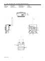
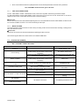
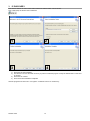
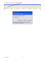
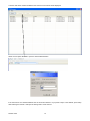
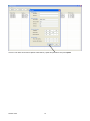
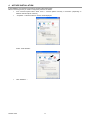
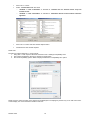
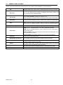
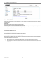
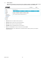
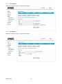
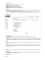
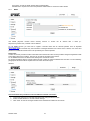
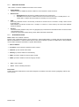
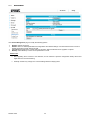
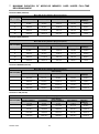
DS1093-104A ENGLISH CONTENTS 1 GENERAL INFORMATION ..................................................................................................................... 4 1.1 SAFETY .................................................................................................................................. 4 1.2 Certifications ........................................................................................................................... 5 1.3 Opening the salesbox ............................................................................................................. 6 2 Installation ............................................................................................................................................... 7 2.1 Ref. 1093/184M11 – Ref. 1093/184M12 installation .............................................................. 7 2.2 Ref. 1093/184M11- Ref. 1093/184M12 PARTS DESCRIPTION ........................................... 8 2.3 Ref. 1093/184M14 parts description ...................................................................................... 9 2.4 Ref.1093/184M15 – Ref.1093/184M16 parts description..................................................... 10 1.3.1 Salesbox content .................................................................................................................................. 6 2.4.1 2.4.2 Lens focus regulation ......................................................................................................................... 11 Micro SD card .................................................................................................................................... 11 2.5 status led charts ................................................................................................................... 11 2.5.1 2.5.2 2.5.3 3 4 5 Ref. 1093/184m11 front LED chart ..................................................................................................... 11 Ref. 1093/184m12 front LED chart ..................................................................................................... 12 RJ45 connector green led chart for Ref. 1093/184m14, 1093/184m15, 1093/184m16 ...................... 12 IP Discovery .......................................................................................................................................... 13 ActiveX installation .............................................................................................................................. 17 IP Camera configuration page ............................................................................................................ 20 5.1 Video settings ....................................................................................................................... 20 5.2 General video settings .......................................................................................................... 21 5.3 Advanced video settings....................................................................................................... 22 5.4 IP Camera configuration ....................................................................................................... 23 5.5 Privacy .................................................................................................................................. 25 5.6 Memory configuration ........................................................................................................... 26 5.6.1 5.6.2 5.6.3 5.6.4 Select memory ................................................................................................................................... 26 micro SD CARD features ................................................................................................................... 26 RECORDING DURATION TIME ........................................................................................................ 26 File list ................................................................................................................................................ 27 5.7 Event settings ....................................................................................................................... 28 5.7.1 5.7.2 Configuration ...................................................................................................................................... 28 Event list............................................................................................................................................. 28 5.7.2.1 5.7.2.2 5.7.2.3 5.7.3 5.7.4 5.7.5 5.7.6 5.7.7 5.7.8 5.7.9 5.7.10 5.7.11 5.8 Events settings ........................................................................................................................................ 29 General settings....................................................................................................................................... 29 Time settings ........................................................................................................................................... 30 Motion Detection ................................................................................................................................ 30 Motion Detection list ........................................................................................................................... 31 Motion Detection settings ................................................................................................................... 31 Event Server ...................................................................................................................................... 32 FTP Server ......................................................................................................................................... 33 SMTP Server ...................................................................................................................................... 33 HTTP Server ...................................................................................................................................... 34 TCP Server ........................................................................................................................................ 34 I/O Server ........................................................................................................................................... 35 Network settings ................................................................................................................... 35 5.8.1 5.8.2 5.8.3 5.8.4 5.8.5 5.9 General .............................................................................................................................................. 35 Advanced ........................................................................................................................................... 36 DDNS ................................................................................................................................................. 37 Wireless Settings................................................................................................................................ 38 Network settings ................................................................................................................................. 38 System configuration ............................................................................................................ 39 5.9.1 5.9.2 5.9.3 5.9.4 5.9.5 DS1093-104A Information ......................................................................................................................................... 39 User.................................................................................................................................................... 40 Date &time ......................................................................................................................................... 41 System time setting ............................................................................................................................ 41 Management ...................................................................................................................................... 42 2 5.9.6 5.9.7 6 7 System Log ........................................................................................................................................ 43 Connections ....................................................................................................................................... 43 Technical specifications ...................................................................................................................... 44 6.1 Ref. 1093/184M11 specifications ......................................................................................... 44 6.2 Ref. 1093/184M12 specifications ......................................................................................... 46 6.3 Ref. 1093/184M14 specifications ......................................................................................... 48 6.4 Ref. 1093/184M15 specifications ......................................................................................... 50 6.5 Ref. 1093/184M16 specifications ......................................................................................... 52 Maximum duration of micro-SD memory card under full-time recording mode ............................ 54 DS1093-104A 3 1 GENERAL INFORMATION Dear Customer, Thank you for choosing this product. This manual will help you to properly use the following URMET S.p.A IP video recording devices: Ref. 1093/184M11 Ref. 1093/184M12 – Ref. 1093/184M14 - Ref. 1093/184M15 - Ref. 1093/184M16. Please read all the information in this manual for a proper and safe usage. We suggest to keep the manual and refer to it whenever necessary. 1.1 SAFETY Electricity Before connecting to electrical outlet, verify the electrical specifications of the device are suitable for the available power source. We suggest to connect the device to electrical outlet via a switch disconnector. In case of misfunctioning, disconnect electrical power from the general switch. Use only the provided power supply. Safety precautions Do not expose the device to rain or humidity and do not insert any solid or liquid object in it to prevent the risk of fire or electrocution. In these events disconnect the device from the electrical outlet and call technical assistance to check it. Do not open the device. Any repair must be made by qualified personnel or by calling the nearest authorized technical assistance center. Keep the device away from children to prevent any, even involuntary, damaging. Do not touch the device with wet hands as it might cause electrical shock or mechanical damages. If the device falls down while working or if the salesbox is damaged, do not continue using it. If usage is continued under such circumstances electrical shocks might take place. Contact the authorized retailer or installer. Installation precautions Do not install the camera in places with possible exposure to rain or humidity without the proper protective case. Do not point the camera directly to sunlight or other intense sources of light, even when turned off. The subject of recording must not be against the light. Do not point the camera against reflective objects. Some light conditions (such as fluorescent color) can affect the recorded colors. Use AUTO-IRIS lens when operating the camera in changing light environments. Do not use this device on any unstable support such as lurching or sloping table to prevent the device from falling and be damaged. If water or any other material should penetrate the camera, stop using it as it might cause fire or electrical shock and contact the authorized retailer or installer. Do not cover the device with any cloth while using to prevent deformation of the external part and inner components heating which might provoke fire, electrical shock or mechanical damages. Do not put magnets or magnetized objects close to the device to prevent functional anomalies. Do not use this device in presence of smoke, steam, humidity, dust or intense vibrations. Do not use the device shortly after moving it from warm to cold environment and vice versa. After moving the device wait three hours before using it: this time is necessary for the device to adapt to the new environment (temperature, humidity, etc.). Usage precautions Check the device is not damaged after removing the packaging. Check the working environment is not too humid and the temperature is within the indicated range. Do not point the camera against sunlight to prevent sensor damages. DS1093-104A 4 Device cleaning Use a dry cloth to remove dust and dirt from the device. If dirt cannot be removed with a dry cloth, use a humid cloth and a neutral cleanser. Do not use spray cleanser for device cleaning. Do not use volatile liquids such as gasoline, alcohol, solvents etc. or chemical treated cloth to clean the device to prevent deformations, damages or scars on the finishing paint. Disconnect the device from the electrical outlet before cleaning. Memory (micro-SD Card) Format the micro-SD card before using it for the first time. Insert the card only in the indicated direction, any forcing could damage it. The micro-SD card can be affected by temperature jump and vibrations. Ignoring these precautions could affect the memory card functioning and might cause the loss of recorded data. In case of repair, we suggest to save the recorded data before taking the card to the repair center. URMET S.p.A. is not in any way responsible for the loss of recorded data. Video recording This device is not designed as a burglar system but mainly to transmit and record video images. URMET S.p.A. is not in any way responsible for loss or damages of the user consequent to theft. Before using the device, record a demo video to verify the correct functionality of this feature. URMET S.p.A. is not in any way responsible for loss of recorded data consequent to wrong setting or usage, device misfunctioning or failure. This device is composed by electronic precision components. Do not hit the device while recording as it might affect the video. Privacy and Copyright The IP camera is designed for surveillance systems. Video recording is subject to the laws applicable to the Country where used.It is forbidden to record images with Copyright. The User is responsible to check and respect all local laws and norms for video signal recording. The manufacturer is NOT in any way liable for any usage of the product which might result not compliant to the relevant norms. For further information please visit http://www.garanteprivacy.it/web/guest/home_en Firmware upgrade Refer to URMET S.p.A. Customer Service Technical Assistance periodically to check availability of firmware upgrades. Network configuration Camera default setting is DHCP mode. If the network does not support dynamic addressing (DHCP), the device will automatically switch to factory IP 192.168.1.200. Use Urmet “IP-Discovery” software to modify the IP address and other network settings to prevent any conflict with other devices on the network. Once the camera is correctly connected and configured on the IP network it will be possible to show video and settings on any PC or smartphone. Network connections When connecting a PC (using Software Client or Browser), any video channel on the PC will be using “unicast” connection (TCP, RTP, UDP). The device can support up to 5 “unicast” connections so it is possible to show the video on maximum 5 remote devices (PC or smartphone) at the same time depending on the available network band. 1.2 CERTIFICATIONS This product is compliant to - R&TTE 1999/5/EC Directive on radio and telecommunication terminal equipment. DS1093-104A 5 1.3 OPENING THE SALESBOX Verify the packaging and the device are not damaged. If any part is missing or damaged, contact the retailer immediately. In this case do not try to use the device. If the device has to be sent back to the retailer or the supplier, use the original packaging. 1.3.1 Salesbox content N°1 IP camera N°1 Antenna (only 1093/184M11, 1093/184M12, 1093/184M15 and 1093/184M16) N°1 Bracket (only 1093/184M11, 1093/184M12, 1093/184M15 and 1093/184M16) N°1 Power supply N°1 Data cable N°1 CD containing full documentation UID and MAC address A5 paper sheet N°1 Quick user guide Please note the included accessories could be modified without notice. DS1093-104A 6 2 INSTALLATION REF. 1093/184M11 – REF. 1093/184M12 INSTALLATION 2.1 Refer to the following steps for easy and quick installation: Take the bracket out of the salesbox Separate the rotating top part from the bracket (just unscrew it until the two parts will detach) Tighten the rotating top part of the bracket first and then the antenna to the camera Tighten the rotating top part to the body of the bracket depending on the chosen position of the camera (see below). WALL INSTALLATION, UP ORIENTED WALL INSTALLATION, DOWNSIDE ORIENTED DS1093-104A WALL INSTALLATION, DOWN ORIENTED FLAT SUPPORT INSTALLATION, UP ORIENTED FLAT SUPPORT INSTALLATION, DOWN ORIENTED 7 WALL INSTALLATION, UPSIDE ORIENTED CIELING INSTALLATION 2.2 REF. 1093/184M11- REF. 1093/184M12 PARTS DESCRIPTION 1 Lens 2 Status LED 3 Focus ring 4 Speaker 5 Microphone 6 Infrared LED 7 Antenna 8 PIR motion sensor 9 Ethernet port 10 Power supply port 11 Bracket hole 12 Micro-SD slot 13 Reset 14 In/Out 15 WPS button 16 Light sensor 14 7 6 3 1 16 13 5 8 10 9 15 11 12 DS1093-104A 8 4 2 2.3 REF. 1093/184M14 PARTS DESCRIPTION 1 Lens 2 Light sensor 3 Infrared LED 4 Transparent cap 5 Cap lock 6 Microphone in (pink) 7 Audio out (green) 8 Video out 9 Power supply port 10 Ethernet port 11 Terminals lock 12 Micro-SD slot 1 2 3 6 7 8 9 4 10 11 5 12 DS1093-104A 9 REF.1093/184M15 – REF.1093/184M16 PARTS DESCRIPTION 2.4 1 Lens 2 Antenna 3 Infrared LED 4 Light sensor 5 Bracket hole 6 Microphone in (pink) 7 Audio out (green) 8 Video out 9 Power supply port 10 Ethernet port 11 Terminals lock 12 Micro-SD slot 2 5 3 1 4 6 12 7 8 9 10 11 Ref. 1093/184M14 Ref. 1093/184M15 and Ref. 1093/184M16 Terminals chart 1 Default = Reset Hardware terminal 2 GND = Ground terminal 3 GND = Ground terminal 4 DIN = Burglar alarm input terminal 5 DOUT = Burglar alarm output terminal 6 COM = Common terminal Connect burglar alarm devices (f.i. sirens) to DOUT and COM terminals Connect burglar alarm sensors to DIN and GND terminals DS1093-104A 10 Short circuit Default and Ground (GND) terminals to reset default parameters and reset factory hardware Ref. 1093/184M11 RJ45 connector green LED chart 2.4.1 LENS FOCUS REGULATION For Ref. 1093/184M11 and Ref. 1093/184M12 model, rotate focus regulation external ring clockwise to adjust. For Ref.1093/184M15 and Ref.1093/184M16 model, remove the top cap and use the two small levers on the lens to adjust focus and zoom. Once finished lock the levers to save the settings. Please note: Connect the camera to the network before adjusting the focus. Ref.1093/184M15 and Ref.1093/184M16 models can also be connected via BNC connector to a monitor with analogic video input. 2.4.2 MICRO SD CARD The camera supports a Micro SD slot for local memory recording. Switch off the camera before inserting or taking out the Micro SD card from the slot. Please note: Disconnect the camera from electrical outlet before replacing the Micro SD card. This camera supports Micro SD / SDHC Class 6 from 4GB to 32GB cards. 2.5 STATUS LED CHARTS 2.5.1 REF. 1093/184M11 FRONT LED CHART Camera Status Description Steady Red 8s – 10s Power on Device starting LED Status Wired network connection or restart after reset to default settings (Access Point mode for WiFi connection) Managed mode for WiFi connection (previously connected to the WiFi network) Slow blinking Red14 times Slow blinking Red 6 times then fast blinking 10-20 times Starting complete Wired network connection or restart after reset to default settings (Access Point mode for WiFi connection) Steady Red Connecting to WiFi router (Managed mode) Camera search router WiFi connection, when found it connects to the network with the password Fast Blinking Red Connecting to WiFi router WiFi connection established or failed Steady Red for 3s then loads Micro SD content Loading Micro SD content Micro-SD loaded or no Micro-SD present All network connections (wired, WiFi access point, WiFi managed) If connected to router (wired or WiFi) or in WiFi Access Point mode Steady Red for 2s, off for 2s, cycling Blinking Red once then steady WiFi connection failed Blinking Red once alternating with fast blinking All network connections Fast Blinking Red before restart FW upgrading Reset default settings DS1093-104A 11 2.5.2 REF. 1093/184M12 FRONT LED CHART Camera Status Description LED Status Steady Orange 8s – 10s Power on Device Starting Starting complete Micro SD card loading Wired connection Red blinking WiFi connection (Access Point or Managed mode) Red blinking for 5s then alternate Green, Red and Orange Wired connection Steady Red WiFi Access Point mode or WiFi connection already established Steady Orange WiFi connection failed Steady Red with Orange blinking Wired connection Red blinking every 2s WiFi Access Point mode or WiFi connection already established Steady Green with Orange blinking for 2s WiFi connection failed Micro SD card loaded or no Micro SD present Wired connection WiFi Access Point mode or WiFi connection already established Green blinking alternating with Red and Orange Steady Red Steady Orange WiFi connection failed Staedy Red with Orange blinking Reset to default settings or FW upgrading Wired connection WiFi Access Point mode or WiFi connection already established Red blinking Reset to default settings WiFi connection failed 2.5.3 Steady Green with Orange blinking Green blinking alternating with Red and Orange RJ45 CONNECTOR GREEN LED CHART FOR REF. 1093/184M14, 1093/184M15, 1093/184M16 Camera Status Description Steady Green 8s – 10s Power on Device starting LED Status Wired network connection or restart after reset to default settings (Access Point mode for WiFi connection) Managed mode for WiFi connection (previously connected to the WiFi network) Slow blinking Green 14 times Slow blinking Green 6 times then fast blinking 10-20 times Starting complete Wired network connection or restart after reset to default settings (Access Point mode for WiFi connection) Steady Green Connecting to WiFi router (Managed mode) Camera search router WiFi connection, when found it connects to the network with the password Fast blinking Green Connecting to WiFi router WiFi connection established or failed Steady Green for 3s then loads Micro SD content Loading Micro SD content Micro-SD loaded or no Micro-SD present All network connections (wired, WiFi access point, WiFi managed) If connected to router (wired or WiFi) or in WiFi Access Point mode Steady Green 2s, off 2s, cycling Green blinking once then steady WiFi connection failed Green blinking once alternate fast blinking All network connections Fast blinking Green before restart FW upgrading Reset default settings DS1093-104A 12 3 IP DISCOVERY This software detects the Urmet Cloud series Camera IP address within a local network. First, install setup.msi file from the included CD. 1 3 1 1) 2) 3) 4) 2 1 4 1 Press Next to start installation. Use Browse to choose the folder in which you prefer to install the program or keep the default folder. Press Next to continue Press Next to continue Press Close after installation completed Start the program from Start menu Programs Network Camera IP Discovery DS1093-104A 13 If the following window pops up press Unlock then Refresh DS1093-104A 14 A window with all the cameras available in the same PC local network will be displayed. Select one and press Connect to open the camera WEB interface. If the camera has an IP address different from the local LAN network or if you prefer to input a new address, press Setup after selecting the camera. It will open the settings menu of that camera. DS1093-104A 15 Choose a User Name and Password (default: admin/admin). Update the parameters then press Update. DS1093-104A 16 4 ACTIVEX INSTALLATION If the installation of an ActiveX component is required, follow these steps. Before connecting the PC you need to configure IE protection as follows: From Internet Explorer Menu select Tools -> Internet Options->Security or Protection (depending on different Internet Explorer versions) “Properties – Internet Protection” window will be displayed. Select “Safe websites”. Click “Websites…”. DS1093-104A 17 The following window will be displayed. Input camera IP address in “Add website to area” Press “Add”. The following confirm window will be displayed Please note Do not thick “Request server check (https:) for all area websites”. DS1093-104A 18 Press “OK” or “Close”. Select “Customized Level” and check: o “Enabled” or “Ask confirmation” is selected for “Initialize and run ActiveX control script not marked as safe” o “Enabled” or “Ask confirmation” is selected for “Download ActiveX control without electronic signature” Press “OK” to confirm and close Internet Options menu. Install Active X from Internet Explorer. Please note Procedure for Internet Explorer 11 on Win 7/8 OS: 1. Using Win 7 or Win 8 open IE Browser and select Tools ->Settings Compatibility View" 2. Add camera IP address in the pop up window as shown below. 3. Check all compatibility options. Select "Display all websites in Compatibility view” option. Please note: the video recording on the camera can be displayed on a webpage by Activex only on PC with one monitor. Correct display can not be assured for double monitor PC. DS1093-104A 19 5 IP CAMERA CONFIGURATION PAGE Use the following URL directly on the browser to enter the IP camera configuration page: http:// <IPcameraaddress>/setup.html On this page the user can modify the IP camera basic and advanced settings. 5.1 Video Main features and advanced settings of video stream Camera Image settings, such as brightness, white balance, etc. Memory Management of data recorded on Micro SD card Events Advanced settings for Events configuration, email sending, instant pictures, etc. Network System Network and Events configuration Firmware version and upgrades, user access management. System information VIDEO SETTINGS DS1093-104A 20 5.2 GENERAL VIDEO SETTINGS The IP camera supports up to 6 different video streams at the same time. Use Live stream window to see the video streams and modify settings. Video streams can be H.264 or Motion JPEG, depending on user configuration. URL Indicates stream name; input a name to indicate the kind of stream you are using. Resolution You can set a different video resolution for different video devices. Please note high resolution requires higher bandwidth. Encode type Select H.264 or MJPEG encoding for the stream in use. H.264 compression is the best compromise between video quality and bandwidth. Frame Rate Set the number of frames per second. For better video quality set an higher frame GOP GOP is short for "Group of Pictures". GOP is a group of consecutive pictures composing an encoded video stream. We suggest to keep the default parameters. JPEG Quality Value ranging from 1 to 88; an higher number indicates a better video quality. [CBR]: short for “Constant Bit Rate”, to be used in limited band condition Video mode [VBR]: short for “Variable Bit Rate”, used to adapt the bit rate to bandwidth to improve video quality [Enhanced CBR]: limits the video stream bit rate within two defined limits. To be used in limited band condition [Enhanced VBR]: sets the higher VBR bit rate. To be used with broadband Bit Rate(k) Bit rate used for video transmission. Bit Rate Max (k) threshold Sets the higher bit rate for both Enhanced CBR and Enhanced VBR. Video delay Only in Enhanced CBR condition, sets the maximum time (milliseconds) during which the maximum bit rate can be used. Quality Sets video stream quality: an higher value indicates higher quality. The minimum threshold is set through Min/Max Quality parameters. MaxQuality Sets video stream maximum quality threshold. 51 indicates the best quality. MinQuality Sets video stream minimum quality threshold. 1 indicates the worst quality. DS1093-104A 21 5.3 ADVANCED VIDEO SETTINGS Digital PT: Use Digital PT function to enable pan and tilt (ration) effect within a selected area. This function is enabled on streams 5 and 6 (these streams will be displayed after selecting Stream page on Video menu). Audio Audio Input source: select a microphone or other audio input device as source (Please note this function may be different depending on the device hardware features). Audio output volume: use this function to adjust audio output volume. Audio Format: select audio compression format “AAC”, “u-LAW” or “Off”. For 3GPP devices (IPhone or other smartphones) with access to the network using NVR surveillance software, “u-LAW” format is suggested. OSD settings: Device name: input a device name typing in the blank field, max 20 digits. Date / Time: Displays date and time on the video stream transmitted from the IP camera. Save: Press “Save” to save settings changes. DS1093-104A 22 5.4 IP CAMERA CONFIGURATION DS1093-104A 23 Enables and disables white balance regulation. WB (White Balance) “Enabled” balances the light in bright and dark conditions to enhance image uniformity. Exposure settings according to brightness, frame rate and bandwidth. Exposure Available parameters are Auto, 50 and 60 kHz. Auto is suggested. Exposure time, gain and diaphragm can also be regulated. Image improvement Image settings can improve image quality. Mirror / Flip Enable/disable these functions if the camera installation requires the image to be turned horizontally or vertically. Gamma correction Regulates gamma correction according to light condition. We suggest not to change this setting. Turns on ICR (IR mechanic filter) according to light sensor activation. This setting is suggested. Coordinates light sensor activation and PIR motion sensor. Auto ICR Turns on ICR when PIR detects motion. Timer: sets an ICR limited working time. ICR / LED GPIN: turns on ICR according to a wired input status. Manual ICR Day: turns off ICR during the day. Night: turns off ICR during the night. IR (Auto): enables b/w mode when infrared light is on. B/W mode B/W: enables black and white image. Color: enables color image. DS1093-104A 24 5.5 PRIVACY Selecting a “privacy” area, it will be obscured from video recording. The device supports up to 3 different privacy areas. To enable privacy area, thick the box after selecting the area with the mouse, then “Save settings” to save changes. DS1093-104A 25 5.6 5.6.1 MEMORY CONFIGURATION SELECT MEMORY Displays the supported Micro SD card parameters. The card contains live recordings and pictures with the following recording settings. Please note: When a Micro SD card is inserted, restart the camera to detect it. Detection time from 20 to 120 seconds depending on Micro SD class. Before inserting the Micro SD card, format it via web user interface “Format” option or via smartphone APP (All files will be deleted permanently. Back up the files before formatting the card). 5.6.2 MICRO SD CARD FEATURES Supports 4GB to 32GB Micro SD card. 5.6.3 RECORDING DURATION TIME Sets the duration time (in seconds) of the recordings on Micro SD card. The recordings can also be saved in a server file (f.i. SAMBA). Before setting the IP address and the server file path on which the file will be saved, check the user has reading/writing rights for files management on the server file. Notes: Video recording is cyclic. Once filled the available memory, new videos will be recorded over old ones. The used space on a new memory support cannot be 0 as the system uses a minimum memory space for its management. DS1093-104A 26 5.6.4 FILE LIST Displays the recorded files present in the Micro SD. To search a file, use the duration time (input starting and finishing time) and click “Search”. A thick box will be displayed to delete the file. DS1093-104A 27 5.7 EVENT SETTINGS This function allows the user to customize the IP camera so that it carries out a specific action in a limited time, when a give situation occurs. For example: take a picture every time a motion is detected and send it via email. The condition is selected on “Kind”. The time when the action must be carried out is selected on “Time setting”. The consequent action is selected on “When detected”. 5.7.1 CONFIGURATION 5.7.2 EVENT LIST Displays the list of events saved. Add: adds a new event. To set a new event, click “Add” on the configuration page to show the available settings. Please note maximum 10 (ten) events are supported. Delete: deletes an event, click on it to select then “Delete”. DS1093-104A 28 5.7.2.1 Events settings 5.7.2.2 General settings Event name: input a name to identify the event which will start an action under a specific condition. Detect from: (Condition) DS1093-104A Continuous Detection: the trigger condition is always enabled. Motion Detection: the action is carried out after a motion detection in some areas selected by the user. Manual Enable: manually determines the trigger condition, enabled on live display page. Click “Manual trigger” to enable. GPIN: the action is carried out when a trigger device connected to terminal 3 or 4 is turned on. Start: the action is carried out when the camera is turned on or restarted. This option is useful to detect unexpected connections. IP change: notifies a change of the camera IP address. 29 5.7.2.3 Time settings Always: IP camera is always ready to detect the selected condition. Event duration time: carries out the action for a selected duration time. Use the mouse to select date and time. Stop: disables any action. Even under the selected condition, the IP camera will not carry out any action. When event occurs (carries out an action) Send Picture: sends the pictures to an FTP server. Send e-mail notification: sends an email to the address set in the network configuration. Send TCP notification: sends a text message to an HTTP port which is ready to receive the message or the command. Send http notification: sends a text message to a TCP port which is ready to receive a message. Rec on storage memory: records pictures on Micro SD card. GPOUT: under the selected condition, enables a device connected to terminal 1 and 2. Picture on storage memory: saves pictures on the selected memory support (see par. 5.2) Please note: To configure FTP server, emails and TCP settings refer to network configuration in the following section EventServer. 5.7.3 MOTION DETECTION Video motion detection generates an alarm signal every time a motion starts or stops within the picture. Up to 3 Inclusion/Exclusion windows can be configured. When configured, the detection window will be displayed in the available trigger conditions list and can be linked to a subsequent action. Please note: Motion detection function might influence other contemporary events. Do not set OSD date and time on the detection window. DS1093-104A 30 5.7.4 MOTION DETECTION LIST Add: up to 3 different areas can be selected. Each one will be identified with a different color: red, green and blue. Pressing Add the minimum Motion detection area will be highlighted. You can enlarge it or move it to cover the area of interest. Delete: from “Motion detection” list, select the name of the area then click “Delete”. OSD On/Off: Select “OSD On” to display on the screen that Motion Detection function is enabled. 5.7.5 MOTION DETECTION SETTINGS Area Name: input a name for the area. Sensitivity: values from 0 to 100; sensitivity grows with higher values. Color: choose a color (red, blue or yellow) for the area where motion detection is enabled. Save: click “Save” to save changes. Delete: click “Reset” to return to default settings. DS1093-104A 31 5.7.6 EVENT SERVER Event Server are designed to receive pictures and/or notification messages. Use Settings > Event > Event Server to configure camera Event Server and input the required information for the selected server. Add FTP: adds an FTP website to send the pictures to. Add HTTP: adds an HTTP server to send text messages to. Add TCP: adds a TCP port to send text messages to. Add SMTP: adds an email address/server to send emails to. Delete: from “Event Server” list, select a server name and click “Delete”. After adding FTP, HTTP, TCP or SMTP server, an information window will pop up where you can input the required information. DS1093-104A 32 5.7.7 FTP SERVER 5.7.8 SMTP SERVER Email sending configuration parameters. DS1093-104A 33 5.7.9 HTTP SERVER Notification messages receiving configuration parameters. 5.7.10 TCP SERVER Notification messages receiving configuration parameters. DS1093-104A 34 5.7.11 5.8 I/O SERVER GPIO: configures Open/Close idle status of the input and output circuit. GPIN: Idle Status: select “Open” or “Closed” for GPIN circuit idle status; GPOUT1: Idle Status: select “Open” or “Closed” for GPOUT circuit idle status. NETWORK SETTINGS Use “Network” configuration page to modify or add advanced settings depending on the network in which the IP camera is installed. Different from “IP Discovery” software which is useful for initial configuration of the network, the “Network” page is a flexible tool to obtain the best performance of the network. General: IP configuration basic settings. Advanced: includes Time Server, Hostname and Service Port. DDNS: access to IP camera with domain name instead of IP address. Wireless (Optional): wireless network settings. 5.8.1 GENERAL DHCP: obtains an IP address via DHCP. Dynamic Host Configuration (DHCP) protocol allows the network administrator to centrally manage and automatically allocate IP addresses on a network. DHCP server is often used to allocate a dynamic IP address but it is also possible to use it for static IP address associated with a specific MAC address. DS1093-104A 35 Static IP Address IP address: input a specific IP address for the IP camera. Netmask: input IP camera subnet mask. Gateway: input the IP address for the Gateway. DNS1: input the IP address for the first group of DNS. DNS2: input the IP address for the second group of DNS. 5.8.2 PPPoE: Use PPPoE function to connect the IP camera directly to ADSL modem for direct access to the internet. To enable, thick PPPoE box and input user name and password. User name and password for direct connection via ADSL modem are provided by the Internet Service Provider (ISP), f.i. National Network Operator. Contact the Network Operator for further information about this service. ADVANCED NTP Configuration Use the following NTP server address. Use this field to input NTP server host name or IP address. Please note: For users who choose PPPoE to access the network: every change of the “Network address” on “NTP Configuration” can freeze the screen for some seconds as the local ISP (Internet Service Provider) has to allocate a new IP address and new values for HTTP, RTSP and FTP port. This happens every time the NTP is changed via PPPoE. HTTP The default number (80) of HTTP port can be changed by the user. This is useful for secure mapping of the port. RTSP RTSP protocol allows a connection client to activate a H.264/MJPEG stream. Thick the box to enable the server and input the RSTP port number. Default number is 554. H.264/MJPEG video streams will not be available if this service is not enabled. FTP Use FTP server to upload firmware upgrade versions and user applications. Thick the box to enable this service. ARP / PING ARP/PING services are a further tool for the user to detect the status of IP camera. For ARP/PING related commands contact the network administrator. RTSP Settings DS1093-104A 36 Anonymous: access the RTSP stream without authentication. Authentication: requires user name and password authentication to access the RSTP stream. 5.8.3 DDNS Use DDNS (Dynamic Domain Name Service) http://www.mycamera.com ) instead of an IP address. function to access the IP camera with a name (f.i. To use DDNS function you need first to register a domain name with an external provider such as DynDNS (www.dyndns.org). Since DDNS function forwards only the information exchanged between Host server and IP camera, user name and password to enable this function have to be provided by the external provider. Please note: Contact the service provider for further information about the domain name. Some providers charge the registration while some others offer it free of charge. The user can choose the provider for this service. To use DDNS function the IP camera must already have an internet access. For further information about IP camera internet access contact the network administrator and refer to “Port forwarding” paragraph of this manual which explains the main issues about this topics. Wireless User must follow this procedure for the first Wireless network connection: 1. 2. 3. Connect the camera to an hub/switch/modem/router using an Ethernet cable. Select “Enable Wireless” to access wireless settings Click “Save” to save the changes and disconnect the Ethernet cable from the camera. DS1093-104A 37 5.8.4 WIRELESS SETTINGS Click “Search” to find the available Access Point on the network. Enable/Disable: Wireless function is disabled by default, enable it to use it instead of a wired connection. Network kind: Master/Slave: thick this option to enable connection to an Access Point. Host-AP: thick this option to enable connection to Wi-Fi devices such as PC or mobile phones. You will be able to configure the camera without connecting to an Access Point. SSID When using Wireless function it is necessary to allocate an Access Point for connection. Usually a router is used as Access Point. SSID identifies the network Access Point. It usually is a number or a name used by the router when Wireless function is enabled. Security: The Access Point (wireless router) uses a cryptography key to authorize and authenticate client connections when using wireless function. Choose the cryptography method among: WPS, WEP, WPA-PSK or WPA-PSK. 5.8.5 NETWORK SETTINGS DHCP: obtains an IP address via DHCP. Dynamic Host Configuration (DHCP) protocol allows the network administrator to centrally manage and automatically allocate IP addresses on a network. DHCP server is often used to allocate a dynamic IP address but it is also possible to use it for static IP address associated to a specific MAC address. Static IP Address IP address: input a specific IP address for the IP camera. Netmask: input IP camera subnet mask. Gateway: input the IP address for the Gateway. DNS1: input the IP address for the first group of DNS. DNS2: input the IP address for the second group of DNS. Save: saves changes. Reset: returns to default parameters. Please Note: Contact the network administrator for the best management of wireless connection and the cryptography method used on the network. DS1093-104A 38 5.9 5.9.1 SYSTEM CONFIGURATION INFORMATION System configuration page shows information about the current status of the IP camera. This is very useful for quick consultation of information without accessing the configuration pages of each function of the camera. DS1093-104A 39 5.9.2 USER Use this page to configure one or more users/profiles to access to IP camera. Enable Anonymous Login: Thick “Enable Anonymous Login” box to enable unrestricted access to IP camera. Add new user then click “Save” to save changes. This option allows access to IP camera without requiring user name and password. Note: User can choose if authorization must be required for access to IP camera. Add new user Click “Add” to add a new user and input the required information then click “Save” to save changes. Administrator: allowed to view and modify IP camera configuration. Operator: allowed to modify only some parameters of IP camera configuration. Viewer: only allowed to view. Note: follow the instructions on user page to select user name and password. Delete user Select one name among user list then click “Delete” to delete it from the list, click “Save” to save changes. DS1093-104A 40 5.9.3 DATE &TIME Shows date and time of IP camera (24hs format). 5.9.4 SYSTEM TIME SETTING Select automatic DST change, if needed. Select day, week, month of change from standard time to daylight saving time (DST start, DST end). Use Sync Mode to select time sync: Sync with local time – sets time according to PC time. Sync with NTP Server – the camera receives time indication every 60 minutes from an NTP server. Manual – user can manually set date and time. Note: if a host name is used for NTP server it is necessary to add a DNS server in “Network settings” menu. Click “Save” to save changes. Click “Reset” to cancel and repeat the selection. DS1093-104A 41 5.9.5 MANAGEMENT Use “Device Management” page to modify the following options: Restart: restarts IP camera. Default: returns to default parameters all configurations but network settings. Use the hardware reset to return to default parameters network settings as well. File upload: upgrades the IP camera with new firmware. Select the file then click “Upgrade” to upload. Backup: select “Backup” to save current parameters on a file. Please note: After upgrading the IP camera to new firmware, do not restore the previous configuration backup file as this might affect the normal functioning. Carefully consider any change on IP camera settings before modifying them. DS1093-104A 42 5.9.6 SYSTEM LOG Use “System Log” to view all information about activities and modification of the device. Actions are displayed in chronological order starting from the old ones. Scroll the list to find the required action. 5.9.7 CONNECTIONS Use “Connections” page to view all active connections. DS1093-104A 43 6 TECHNICAL SPECIFICATIONS 6.1 REF. 1093/184M11 SPECIFICATIONS Main features: Video compression H.264 & MJPEG Resolution HD 720P,25 Frame per second ONVIF Compatible Up to 6 different video streams Infrared LED for night vision Micro-SD for local storage (*) Integrated Speaker & Microphone for bidirectional audio Wi-fi 802.11 bgn Plug & Play Connection to mobile devices (Android, iOS) Please note (*)Suggested models: SanDisk – Kingston Video & Camera Video profiles & Frame Rate S1: 1280 x 720 25 FPS H.264 / MJPEG S2: 640 x 360 25 FPS H.264 / MJPEG S3: 320 x 180 25 FPS H.264 S4: 320 x 180 25 FPS MJPEG S5: 160 x 96 25 FPS H.264 S6: 160 x 96 25 FPS MJPEG Bit Rate 128K ~ 6Mbits/sec (CBR/VBR configurable) Flash 16MB Network Performance Up to 10 connections at the same time (max 5 in Cloud) Total band: 45 Mbps Video 6 different video streams H.264 & Motion JPEG VBR/CBR/GOP for quality/bitrate control Integrated Date/text on OSD RTSP URI Digital PTZ From image area Sensor 1/4” CMOS WDR Digital Minimum brightness 1 ~ 10,000 Lux Lens f=3.6 mm F1.9 Night&Day ICR Auto (managed by program or light sensor) or Manual IR LEDs 8 Image adjustment Brightness, Saturation, Color, Contrast, Exposure, White balance, Rotation, Flip/Mirror, Automatic gain control Trigger Program, Motion detection, at restart Action Send picture via FTP, Save video and picture on Micro-SD card Email and TCP notification Event Local memory Micro SD (min 4GB, max 32GB, class 6 or higher) Audio compression G.711 (u-LAW) Plug & Play Mobile App for Android andiOS DS1093-104A 44 Network Network interface 10BASE-T/100BASE-TX Protocols HTTP, HTTPS, TCP/IP, UDP, SMTP, FTP, PPPoE, DHCP, DDNS, NTP, DNS, ARP, RSTP, RTP, UPnP Security 3-level protection with password (Administrator, Operator, Viewer) Wireless 802.11 bgn System requirement PC CPU: Pentium 4 @ 2.6Ghz RAM: 1G Graphics card: 256MB OS Microsoft Windows XP/Vista /Windows 7 DirectX 9 Browser Microsoft Internet Explorer 9 or higher, Mozilla Firefox, Google Chrome, Safari. Working conditions Power supply Switching AC/DC power supply. AC100 ~ 240V input; DC 5V/ 2A output Power consumption <8 W Working temperature 0°C ~ 50°C Working humidity 20% ~ 80% RH (without condensation) Dimensions 70 (T) x 38 (L) x 88.5 (H) mm Net weight 90g (camera) Certifications CE, FCC, ROHS I/O Connectors Salesbox content DS1093-104A 1 x RJ45 10BASE-T/100BASE-TX 1 x power supply Jack 1 x slot Micro SD 1 x Default button 1 x WPS button 1 x Camera 1 x Antenna 1 x Bracket 1 x CD (user manual and software); 1 x quick user guide; 1 x Ethernet cable 1 x power supply AC/DC 5V/2A 45 6.2 REF. 1093/184M12 SPECIFICATIONS Main features: Video compression H.264 & MJPEG Resolution HD 720P, 25 Frame per second ONVIF Compatible Up to 6 different video streams Infrared LED for night vision Micro-SD for local storage (*) Integrated Speaker & Microphone for bidirectional audio Wi-fi 802.11 bgn Plug & Play Connection to mobile devices (Android, iOS) Removable IR cut mechanic filter Input & Output alarm PIR motion sensor Please note (*)Suggested models: SanDisk – Kingston Video &Camera S1: 1280 x 720 25 FPS H.264 / MJPEG S2: 640 x 360 25 FPS H.264 / MJPEG Video profiles & Frame Rate S3: 320 x 180 25 FPS H.264 S4: 320 x 180 25 FPS MJPEG S5: 160 x 96 25 FPS H.264 S6: 160 x 96 25 FPS MJPEG Bit Rate 128K ~ 6Mbits/sec (CBR/VBR configurable) Flash 16MB Network Performance Video Up to 10 connections at the same time (max 5 in Cloud) Total band: 45 Mbps 6 different video streams H.264 & Motion JPEG VBR/CBR/GOP for quality/bitrate control Integrated Date/text on OSD RTSP URI Digital PTZ From image area Sensor 1/4” CMOS WDR Digital Minimum brightness 1 ~ 10,000 Lux Lens f=3.6 mm F1.9 Night&Day ICR Auto (managed by program, GPIN or light sensor) or Manual IR LEDs 1 x IN/1 x OUT for preconfigured Open/Close alarms Video profiles & Frame Rate 8 Sensor PIR motion sensor Image adjustment Brightness, Saturation, Color, Contrast, Exposure, White balance, Rotation, Flip/Mirror, Automatic gain control Trigger Program, Motion detection, at restart Action Send picture via FTP, Save video and picture on Micro-SD card Email and TCP notification Event Local memory Micro SD (min 4GB, max 32GB, class 6 or higher) Audio compression G.711 (u-LAW) Plug & Play Mobile App for Android and iOS DS1093-104A 46 Network Network interface 10BASE-T/100BASE-TX Protocols HTTP, HTTPS, TCP/IP, UDP, SMTP, FTP, PPPoE, DHCP, DDNS, NTP, DNS, ARP, RSTP, RTP, UPnP Security 3-level protection with password (Administrator, Operator, Viewer) Wireless 802.11 bgn System requirement PC CPU: Pentium 4 @ 2.6Ghz RAM: 1G Graphics card: 256MB OS Microsoft Windows XP/Vista /Windows 7 DirectX 9 Browser Microsoft Internet Explorer 9 or higher, Mozilla Firefox, Google Chrome, Safari. Working conditions Power supply switching AC/DC power supply. AC100 ~ 240V input; DC 5V/ 2A output Power consumption <8 W Working temperature 0°C ~ 50°C Working humidity 20% ~ 80% RH (without condensation) Dimensions 70 (T) x 38 (L) x 88.5 (H) mm Net weight 90g (camera) Certifications CE, FCC, ROHS I/O Connectors 1 x RJ45 10BASE-T/100BASE-TX 1 x power supply Jack 1 x slot Micro SD 1 x Default button 1 x WPS button Salesbox content 1 x Camera 1 x Antenna 1 x Bracket 1 x CD (user manual and software); 1 x quick user guide; 1 x Ethernet cable 1 x power supply AC/DC 5V/2A DS1093-104A 47 6.3 REF. 1093/184M14 SPECIFICATIONS Main features: Video compression H.264 & MJPEG Resolution HD 720P,25 Frame per second ONVIF Compatible Up to 6 different video streams Infrared LED for night vision up to 20m Micro-SD for local storage (*) Integrated Speaker & Microphone for bidirectional audio Wi-fi 802.11 bgn (with dongle) Power-over-Ethernet 802.3af Analogic output Plug & Play Connection to mobile devices (Android, iOS) Removable IR cut mechanical filter Input & Output alarms Please note (*)Suggested models: SanDisk – Kingston Video &Camera Video profiles & Frame Rate S1: 1280 x 720 25 FPS H.264 / MJPEG S2: 640 x 360 25 FPS H.264 / MJPEG S3: 320 x 180 25 FPS H.264 S4: 320 x 180 25 FPS MJPEG S5: 160 x 96 25 FPS H.264 S6: 160 x 96 25 FPS MJPEG Bit Rate 128K ~ 6Mbits/sec (CBR/VBR configurable) Flash Up to 10 connections at the same time (max 5 in Cloud) Total band: 45 Mbps Network Performance 6 different video streams H.264 & Motion JPEG VBR/CBR/GOP for quality/bitrate control Integrated Date/text on OSD RTSP URI Video From image area Digital PTZ CMOS 1/4” Sensor 720P 1 Megapixel Sensor Digital WDR 0 ~ 10,000 Lux Lens f=3.6 mm F1.9 Night&Day ICR Auto (managed by program, GPIN or light sensor) or Manual In / OutAlarm 1 x IN/1 x OUT for preconfigured Open/Close alarms IR LED 24, distance: 20 meters Image adjustment Brightness, Saturation, Color, Contrast, Exposure, White balance, Rotation, Flip/Mirror, Automatic gain control Trigger Program, Motion detection, at restart Action Send picture via FTP, Save video and picture on Micro-SD card Email and TCP notification Event Local memory Micro SD (min 4GB, max 32GB, class 6 or higher) Audio compression G.711 (u-LAW) Plug & Play Mobile App for Android and iOS DS1093-104A 48 Network Network interface 10BASE-T/100BASE-TX Protocols HTTP, HTTPS, TCP/IP, UDP, SMTP, FTP, PPPoE, DHCP, DDNS, NTP, DNS, ARP, RSTP, RTP, UPnP Security 3-level protection with password (Administrator, Operator, Viewer) Wireless 802.11 bgn System requirement PC CPU: Pentium 4 @ 2.6Ghz RAM: 1G Graphics card: 256MB OS Microsoft Windows XP/Vista /Windows 7 DirectX 9 Browser Microsoft Internet Explorer 9 or higher, Mozilla Firefox, Google Chrome, Safari. Working conditions Power Supply Power Over ethernet Switching AC/DC power supply. AC100 ~ 240V input ; DC 12V/ 1 A output PoE 802.3af Power consumption <8 W Working temperature 0°C ~ 50°C Working humidity 20% ~ 80% RH (without condensation) Dimensions 111.4 (T) x 83(H) mm Net weight 315 g (only camera) Certifications CE, FCC, ROHS I/O Connectors 1 x RJ45 10BASE-T/100BASE-TX 1 x Jack power supply 1 x BNC connector video output 1 x Jack Audio In 1 x Jack Audio Out 1 x clamping strip 1 x inner Micro SD Card slot Terminal pin: 1 x input; 1 x output; 2 x ground; 1 x common 1 x Default Salesbox content DS1093-104A 1 x Camera 1 x Antenna 1 x CD (user manual and software); 1 x quick user guide; 1 x mounting template; 1 x Ethernet cable 1 x Power supply AC/DC 12V/1A 49 6.4 REF. 1093/184M15 SPECIFICATIONS Main features: Video compression H.264 & MJPEG Resolution HD 720P,25 Frame per second ONVIF Compatible Up to 6 different video streams Infrared LED for night vision up to 20m Micro-SD for local storage (*) Integrated Speaker & Microphone for bidirectional audio Wi-fi 802.11 bgn (with dongle) Power-over-Ethernet 802.3af Analogic output Plug & Play Connection to mobile devices (Android, iOS) Removable IR cut mechanical filter Input & Output alarms IP66 Waterproof case Please note (*)Suggested models: SanDisk – Kingston Video & Telecamera Video profiles & Frame Rate S1: 1280 x 720 S2: 640 x 360 S3: 320 x 180 S4: 320 x 180 25 FPS 25 FPS 25 FPS 25 FPS H.264 / MJPEG H.264 / MJPEG H.264 MJPEG S5: 160 x 96 25 FPS H.264 S6: 160 x 96 25 FPS MJPEG Bit Rate 128K ~ 6Mbits/sec (CBR/VBR configurable) Network Performance Up to 10 connections at the same time (max 5 in Cloud) Total band: 45 Mbps Video 6 different video streams H.264 & Motion JPEG VBR/CBR/GOP for quality/bitrate control Integrated Date/text on OSD RTSP URI Digital PTZ From image area Sensor CMOS 1/4” Sensor720P 1 Megapixel WDR Digital Minimum brightness 0 ~ 10,000 Lux Lens f=3.6 mm F1.9 Night&Day ICR Auto (managed by program, GPIN or light sensor) or Manual In / OutAlarm 1 x IN/1 x OUT for preconfigured Open/Close alarms IR LED 24, distance: 20 meters Image adjustment Brightness, Saturation, Color, Contrast, Exposure, White balance, Rotation, Flip/Mirror, Automatic gain control Trigger Program, Motion detection, at restart Action Send picture via FTP, Save video and picture on Micro-SD card Email and TCP notification Event Local memory Micro SD (min 4GB, max 32GB, class 6 or higher) Audio compression G.711 (u-LAW) Plug & Play Mobile App for Android and iOS DS1093-104A 50 Network Network interface 10BASE-T/100BASE-TX Protocols HTTP, HTTPS, TCP/IP, UDP, SMTP, FTP, PPPoE, DHCP, DDNS, NTP, DNS, ARP, RSTP, RTP, UPnP Security 3-level protection with password (Administrator, Operator, Viewer) Wireless 802.11 bgn System requirement PC CPU: Pentium 4 @ 2.6Ghz RAM: 1G Graphics card: 256MB OS Microsoft Windows XP/Vista /Windows 7 DirectX 9 Browser Microsoft Internet Explorer 9 or higher, Mozilla Firefox, Google Chrome, Safari. Working Conditions Power supply Power Over Ethernet Power consumption Switching AC/DC power supply. AC100 ~ 240V input; DC 12V/ 1A output PoE 802.3af <8 W Working temperature 0°C ~ 50°C Working humidity 20% ~ 80% RH (without condensation) Dimensions 70 (T) x 111(L) x 70 (H) mm Net weight 610 g (only camera) Certifications CE, FCC, ROHS I/O Connectors 1 x RJ45 10BASE-T/100BASE-TX 1 x power supply jack 1 x BNC connector for video output 1 x Audio In 1 x Audio Out 1 x clamping strip 1 x inner Micro SD Card slot Terminal pin: 1 x input; 1 x output; 2 x ground; 1x common 1 x Default Salesbox content DS1093-104A 1 x Camera 1 x Antenna 1 x Bracket 1 x CD (user manual and software); 1 x quick user guide; 1 x Ethernet cable 1 x power supply AC/DC 12V/1A 51 6.5 REF. 1093/184M16 SPECIFICATIONS Main features: Video compression H.264 & MJPEG Resolution HD 720P,25 Frame per second ONVIF Compatible Up to 6 different video streams Infrared LED for night vision up to 20m Micro-SD for local storage (*) Integrated Speaker & Microphone for bidirectional audio Wi-fi 802.11 bgn (with dongle) Power-over-Ethernet 802.3af Analogic output Plug & Play Connection to mobile devices (Android, iOS) Removable IR cut mechanical filter Input & Output alarms IP66 Waterproof case Please note (*)Suggested models: SanDisk – Kingston Video & Camera S1: 1280 x 720 S2: 640 x 360 Video profiles& Frame S3: 360 x 180 Rate S4: 360 x 180 S5: 180 x 90 S6: 180 x 90 25 FPS 25 FPS 25 FPS 25 FPS H.264 MJPEG H.264 MJPEG 25 FPS 25 FPS H.264 JPEG Bit Rate 128K ~ 6Mbits/sec (CBR/VBR configurable) Network Performance Up to 10 connections at the same time (max 5 in Cloud) Total band: 45 Mbps Video 6 different video streams H.264 & Motion JPEG VBR/CBR/GOP for quality/bitrate control Integrated Date/text on OSD RTSP URI Digital PTZ From image area Sensor CMOS 1/4” Sensor 720P 1 Megapixel WDR Digital Minimum brightness 0 ~ 10,000 Lux Lens Varifocal f=3.3 ~ 12 mm F1.4 Night&Day ICR Auto (managed by program, GPIN or light sensor) or Manual In / OutAlarm 1 x IN/1 x OUT for preconfigured Open/Close alarms IR LED 24, distance: 20 meters Image adjustment Brightness, Saturation, Color, Contrast, Exposure, White balance, Rotation, Flip/Mirror, Automatic gain control Trigger Program, Motion detection, at restart Action Send picture via FTP, Save video and picture on Micro-SD card Email and TCP notification Event Local memory Micro SD (min 4GB, max 32GB, class 6 or higher) Audio compression Plug & Play G.711 (u-LAW) Mobile App for Android and iOS DS1093-104A 52 Network Network interface 10BASE-T/100BASE-TX Protocols HTTP, HTTPS, TCP/IP, UDP, SMTP, FTP, PPPoE, DHCP, DDNS, NTP, DNS, ARP, RSTP, RTP, UPnP Security 3-level protection with password (Administrator, Operator, Viewer) Wireless 802.11 bgn System requirement PC CPU: Pentium 4 @ 2.6Ghz RAM: 1G Graphics card: 256MB OS Microsoft Windows XP/Vista /Windows 7 DirectX 9 Browser Microsoft Internet Explorer 9 or higher, Mozilla Firefox, Google Chrome, Safari. Working conditions Power supply Switching AC/DC power supply. AC100 ~ 240V input; DC 12V/ 1A output Power Over Ethernet PoE 802.3af Power consumption <8W Working temperature 0°C ~ 50°C Working humidity 20% ~ 80% RH (without condensation) Dimensions 70 (T) x 111(L) x 70 (H) mm Net weight 700 g (only camera) Certifications CE, FCC, ROHS I/O Connectors 1 x RJ45 10BASE-T/100BASE-TX 1 x power supply jack 1 x BNC connector for video output 1 x Audio In 1 x Audio Out 1 x terminal block 1 x inner Micro SD Card slot Terminal pin: 1 x input; 1 x output; 2 x ground; 1x common 1 x Default Salesbox content DS1093-104A 1 x Camera 1 x Antenna 1 x Bracket 1 x CD (user manual and software); 1 x quick user guide; 1 x Ethernet cable 1 x power supply AC/DC 12V/1A 53 7 MAXIMUM DURATION OF MICRO-SD MEMORY CARD UNDER FULL-TIME RECORDING MODE Resolution MAX (1280x720) Micro-SD memory duration (days) and (hours) Video Quality SD Card [GB] Minimum (128Kbps) Low (192Kbps) Medium (256Kbps) High (384Kbps) 4 8 16 32 2,54 d 60,88 h 5,39 d 129,32 h 11,09 d 266,22 h 22,50 d 540,02 h 1,69 d 40,58 h 3,59 d 86,22 h 7,40 d 177,48 h 15 d 360,01 h 1,27 d 30,44 h 2,69 d 64,66 h 5,55 d 133,11 h 11,25 d 270,01 h 0,85 d 20,29 h 1,80 d 43,11 h 3,70 d 88,74 h 7,50 d 180,01 h Maximum (512Kbps) 0,63 d 15,22 h 1,35 d 32,33 h 2,77 d 66,56 h 5,63 d 135 h Resolution HIGH (640x360) Micro-SD memory duration (days) and (hours) SD Card [GB] Minimum (128Kbps) 4 8 16 32 2,54 d 60,88 h 5,39 d 129,32 h 11,09 d 266,22 h 22,50 d 540,02 h Low (192Kbps) 1,69 d 40,58 h 3,59 d 86,22 h 7,40 d 177,48 h 15 d 360,01 h Video Quality Medium (256Kbps) 1,27 d 30,44 h 2,69 d 64,66 h 5,55 d 133,11 h 11,25 d 270,01 h High (384Kbps) 0,85 d 20,29 h 1,80 d 43,11 h 3,70 d 88,74 h 7,50 d 180,01 h Maximum (512Kbps) 0,63 d 15,22 h 1,35 d 32,33 h 2,77 d 66,56 h 5,63 d 135 h Resolution MEDIUM (320x180) Micro-SD memory duration (days) and (hours) SD Card [GB] 4 8 16 32 Minimum (64Kbps) 5,07 d 121,75 h 10,78 d 258,65 h 22,19 d 532,44 h 45 d 1080,03 h Video Quality Medium (128Kbps) Low (96Kbps) 3,38 d 81,17 h 7,18 d 172,43 h 14,79 d 354,96 h 30 d 720,02 h 2,54 d 60,88 h 5,39 d 129,32 h 11,09 d 266,22 h 22,50 d 540,02 h High (192Kbps) 1,69 d 40,58 h 3,59 d 86,22 h 7,40 d 177,48 h 15 d 360,01 h Maximum (256Kbps) 1,27 d 30,44 h 2,69 d 64,66 h 5,55 d 133,11 h 11,25 d 270,01 h Resolution LOW (160x96) Micro-SD memory duration (days) and (hours) SD Card [GB] 4 8 16 32 DS1093-104A Minimum (32Kbps) 10,15 d 243,50 h 21,55 d 517,30 h 44,37 d 1064,89 h 90 d 2160,07 h Video Quality Medium (64Kbps) Low(48Kbps) 6,76 d 162,34 h 14,37 d 344,86 h 29,58 d 709,92 h 60 d 1440,04 h 5,07 d 121,75 h 10,78 d 258,65 h 22,19 d 532,44 h 45 d 1080,03 h 54 High (96Kbps) 3,38 d 81,17 h 7,18 d 172,43 h 14,79 d 354,96 h 30 d 720,02 h Maximum (128Kbps) 2,54 d 60,88 h 5,39 d 129,32 h 11,09 d 266,22 h 22,50 d 540,02 h DS1093-104A 55


![Subject: [MB] 1987 W126 intermittent climate control](http://vs1.manualzilla.com/store/data/006030956_1-f014f75cb14526db0f9eb72ec9889b7e-150x150.png)