1
DUEMMEGI Contatto Contatto MCP XT Programmable Control Module User's Manual Release 2.1 – September 2011 HOME AND BUILDING AUTOMATION Via Longhena 4 - 20139 MILANO Tel. 02/57300377 - FAX 02/55213686 www.duemmegi.it Contatto MCP XT – User's manual DUEMMEGI INDEX A1- CHANGES MADE TO THIS MANUAL IN RESPECT TO THE PREVIOUS RELEASE..............................4 A2- RECOMMENDATIONS.............................................................................................................................4 1- MAIN FEATURES.........................................................................................................................................5 1.1- Required Hardware and Software tools................................................................................................5 1.2- Main features of MCP XT.....................................................................................................................5 1.3- Terminology and syntax........................................................................................................................5 2- EQUATIONS: TYPES AND SYNTAX...........................................................................................................6 2.1- Equations for the system configuration.................................................................................................6 2.1.1- Configuration of the modules...................................................................................................6 2.1.2- Power ON status.....................................................................................................................6 2.1.3- Status of fault input modules...................................................................................................6 2.1.4- Communication Protocol..........................................................................................................7 2.1.5- Address of MCP XT.................................................................................................................7 2.1.6- Identifier of MCP XT................................................................................................................7 2.1.7- Directive for the calculation of sunrise, sunset and sun position..............................................7 2.1.8- Publishing on the bus the status of virtual points and value of registers..................................8 2.1.9- Management of fault modules.................................................................................................9 2.1.10- Alignment of the outputs........................................................................................................9 2.1.11- Data exchange between MCP XT controllers........................................................................9 2.1.12- Number of nodes in a MCP XT network..............................................................................12 2.2- Event triggered Equations...................................................................................................................12 2.2.1- Logic equations......................................................................................................................12 2.2.2- SET – RESET equations.......................................................................................................12 2.2.3- TOGGLE equations...............................................................................................................13 2.2.4- COUNTER Equations............................................................................................................14 2.2.5- THRESHOLD Equations........................................................................................................15 2.2.6- TIMER Equations...................................................................................................................16 2.2.7- Equations for mathematical and logic calculation..................................................................17 2.2.8- Equations for binary code generation....................................................................................17 2.2.9- Equations for recording status changes (EVENT).................................................................18 2.2.10- Equations for recording value changes (LOG).....................................................................19 2.2.11- Management of the external counter modules (ModCNT)...................................................20 2.3- Time triggered Equations....................................................................................................................20 2.3.1- Scheduler Equations..............................................................................................................20 2.4- Macro..................................................................................................................................................22 3- SCRIPT......................................................................................................................................................24 3.1- Summary............................................................................................................................................24 3.2- Keywords and syntax..........................................................................................................................25 3.2.1- Using the TRIGGER..............................................................................................................25 3.2.2- VAR, GLOBAL VAR and EXTERN VAR................................................................................26 3.2.3- Logic and Mathematical operations.......................................................................................26 3.2.4- IF…THEN…ELSE…ENDIF...................................................................................................27 3.2.5- CARRY and ZERO................................................................................................................28 3.2.6- DEFINE.................................................................................................................................28 3.2.7- GOTO....................................................................................................................................30 3.2.8- SUBROUTINES and FUNCTIONS........................................................................................30 3.2.9- BIT(x).....................................................................................................................................33 3.2.10- WORD(x) and pointers........................................................................................................35 3.2.11- @RAM k and @WORD k....................................................................................................36 Page 2 of 78 Rel.: 2.1 September 2011 DUEMMEGI s.r.l. - Via Longhena, 4 – 20139 MILANO Tel. 02/57300377 - Fax 02/55213686 – www.duemmegi.it DUEMMEGI MCP XT – User's manual Contatto 3.2.12- SWAP(x)..............................................................................................................................36 3.2.13- RANDOM(0)........................................................................................................................36 3.2.14- BMASK(x)............................................................................................................................37 4- PROGRAM WRITING................................................................................................................................38 4.1- Rule for program writing.....................................................................................................................38 4.2- Compiling the program.......................................................................................................................40 4.3- Uploading the program to MCP XT memory.......................................................................................40 5- SETTING UP..............................................................................................................................................41 5.1- Connections........................................................................................................................................41 5.2- Baud Rate selection............................................................................................................................42 5.3- RS232 and RS485 serial ports of MCP XT.........................................................................................43 5.4- WEBS communication port.................................................................................................................43 6- DIAGNOSTICS...........................................................................................................................................44 6.1- Diagnostics of CONTATTO system through MCP XT.........................................................................44 7- TECHNICAL CHARACTERISTICS.............................................................................................................45 8- OUTLINE DIMENSIONS.............................................................................................................................45 9- FXP-XT COMMUNICATION PROTOCOL..................................................................................................46 9.1- Messages format ad meaning............................................................................................................46 9.2- RAM memory mapping.......................................................................................................................48 9.2.1- Main RAM memory mapping.................................................................................................48 9.2.2- Microcontroller RAM memory mapping..................................................................................50 10- MCP IDE: INTEGRATED DEVELOPMENT ENVIRONMENT FOR APPLICATIONS USING MCP XT....51 10.1- Description of the software package.................................................................................................51 10.2- MCP IDE...........................................................................................................................................51 10.2.1- MCP IDE..............................................................................................................................55 10.2.2- Program transferring............................................................................................................55 10.3- MCP VISIO.......................................................................................................................................56 10.3.1- The Groups of MCP VISIO..................................................................................................57 10.3.2- The Projects of MCP VISIO.................................................................................................60 10.3.3- The Simulator of MCP VISIO...............................................................................................60 11- MODBUS COMMUNICATION PROTOCOL.............................................................................................61 11.1- Abstract............................................................................................................................................61 11.2- Supported MODBUS functions.........................................................................................................61 11.3- Example of MODBUS functions........................................................................................................61 11.3.1- Function 1: Reading the digital output status.......................................................................62 11.3.2- Function 2: Reading the digital input status.........................................................................63 11.3.3- Function 3: Reading the registers (RAM memory)...............................................................64 11.3.4- Function 4: Reading analog inputs.......................................................................................66 11.3.5- Function 5: Command of a single output digital point..........................................................66 11.3.6- Function 6: Writing a single register (RAM memory)...........................................................66 11.3.7- Function 16: Writing multiple registers (RAM memory)........................................................66 11.4- Tables for relationship Words-Parameters of MCP XT.....................................................................69 11.4.1- Physical inputs.....................................................................................................................70 11.4.2- Physical outputs...................................................................................................................71 11.4.3- Virtual points........................................................................................................................72 11.4.4- Registers.............................................................................................................................74 11.4.5- Counters..............................................................................................................................76 DUEMMEGI s.r.l. - Via Longhena, 4 – 20139 MILANO Tel. 02/57300377 - Fax 02/55213686 – www.duemmegi.it Rel.: 2.1 September 2011 Page 3 of 78 Contatto MCP XT – User's manual DUEMMEGI A1- CHANGES MADE TO THIS MANUAL IN RESPECT TO THE PREVIOUS RELEASE Par.2.1.7 Par.2.1.8 Added details about azimuth and elevation of the sun Added instruction for the publishing on the bus of virtual points and registers A2- RECOMMENDATIONS WARNING: this manual applies to MCP XT with the following firmwares: Main microcontroller: 3.5 or higher Secondary microcontroller: 2.3 or higher The features described in this manual require the program MCP IDE release 3.0.6 or higher. This manual assumes that the user have an adequate knowledge about the Contatto bus system. Correct disposal of this product (Waste Electrical & Electronic Equipment) (Applicable in the European Union and other European countries with separate collection systems). This marking on the product, accessories or literature indicates that the product should not be disposed of with other household waste at the end of their working life. To prevent possible harm to the environment or human health from uncontrolled waste disposal, please separate these items from other types of waste and recycle them responsibly to promote the sustainable reuse of material resources. Household users should contact either the retailer where they purchased this product, or their local government office, for details of where and how they can take these items for environmentally safe recycling. This product and its electronic accessories should not be mixed with other commercial wastes for disposal. Specifically about the battery, check local regulations for correct disposal. Never use municipal waste. Installation and use restrictions Standards and regulations The design and the setting up of electrical systems must be performed according to the relevant standards, guidelines, specifications and regulations of the relevant country. The installation, configuration and programming of the devices must be carried out by trained personnel. The installation and the wiring of the bus line and the related devices must be performed according to the recommendations of the manufacturers (reported on the specific data sheet of the product) and according to the applicable standards. All the relevant safety regulations, e.g. accident prevention regulations, law on technical work equipment, must also be observed. Safety instructions Protect the unit against moisture, dirt and any kind of damage during transport, storage and operation. Do not operate the unit outside the specified technical data. Never open the housing. If not otherwise specified, install in closed housing (e.g. distribution cabinet). Earth the unit at the terminals provided, if existing, for this purpose. Do not obstruct cooling of the units. Keep out of the reach of children. Setting up The physical address assignment and the setting of parameters (if any) must be performed by the specific softwares provided together the device or by the specific programmer. For the first installation of the device proceed according to the following guidelines: • Check that any voltage supplying the plant has been removed • Assign the address to module (if any) • Install and wire the device according to the schematic diagrams on the specific data sheet of the product • Only then switch on the 230Vac supplying the bus power supply and the other related circuits Applied standards This device complies with the essential requirements of the following directives: 2004/108/CE (EMC) 2006/95/CE (Low Voltage) 2002/95/CE (RoHS) EN 55022 Class B Note Technical characteristics and this data sheet are subject to change without notice. Page 4 of 78 Rel.: 2.1 September 2011 DUEMMEGI s.r.l. - Via Longhena, 4 – 20139 MILANO Tel. 02/57300377 - Fax 02/55213686 – www.duemmegi.it DUEMMEGI MCP XT – User's manual Contatto 1- MAIN FEATURES 1.1- Required Hardware and Software tools To use MCP XT, the software tools MCP IDE is required, running on a PC (WXP, WVista, W7). Minimum hardware required: 800MHz processor and 512 Mbytes minimum RAM. MCP IDE software tools also provides MCP Visio program, allowing to display in a graphical way the status of the field and all parameters of MCP XT, and other programs allowing specific function. 1.2- Main features of MCP XT 2032 virtual digital points 1024 16-bit registers 1024 16-bit counters 512 16-bit timers 127 real input addresses up to 4-channel 16-bit each one 127 real output addresses up to 4-channel 16-bit each one Special virtual points: • V2014: activated during times from sunrise to sunset • V2013: reserved • V2012: activated when a communication loss on COM2 (RS485) occurs for a time longer than 5 seconds • V2011: activated when a communication loss on COM1 (RS232) occurs for a time longer than 5 seconds • V2010: activated 0.5 seconds after the end of initialization procedure • V2009: the buffer of analog event (LOG or LOGC) is full or old events have been overwritten • V2008: the buffer of binary event (EVENT or EVENTC) is full or old events have been overwritten • V2007: reserved • V2006: reserved • V2005: error during the execution of a script (e.g. not valid instruction) • V2004: timeout during the execution of a script (>500msec) • V2003: 1sec period clock (toggle its status every 0.5 seconds) • V2002: bus failure • V2001: module failure 1.3- Terminology and syntax In this manual, some symbols and notations will be used; the meaning of these is here bottom explained. General: DI real or virtual digital input DO real or virtual digital output AI analog input or generic register AO analog output or generic register Ri generic register Addresses, channels, points: O3.1 point 1 of output 3 (channel 1) O3:1.1 exactly as the previous one O3:1.2 point 2 of channel 1 of output module 3 AO15:1 channel 1 of output module 15 AI20:2 channel 2 of input module 20 R12 register R12 R14.5 bit 5 of register R14 (for script only) V100 virtual point 100 V17..V32 all virtual point from V17 to V32 O3:1.1..O4:2.16 all output points from O3:1.1 to O4:2.16 DUEMMEGI s.r.l. - Via Longhena, 4 – 20139 MILANO Tel. 02/57300377 - Fax 02/55213686 – www.duemmegi.it Rel.: 2.1 September 2011 Page 5 of 78 Contatto Numbers: 328 0b0001010011111011 0b11110010 0x14FB MCP XT – User's manual DUEMMEGI decimal number 16-bit binary number 8-bit binary number 16-bit hexadecimal number Note: the channel of an input or output module, if not specified, will be assumed 1. 2- EQUATIONS: TYPES AND SYNTAX 2.1- Equations for the system configuration 2.1.1- Configuration of the modules Specify the module installed in the system (see MCP IDE Keyword List). MOD8I/A MOD8I/A MOD8R MOD4-4R MOD2DM MOD2DM = = = = = = (I1) (I2), (I3) (O11) (I4, O12) (I13, I14, O13, O14) (I15, I16, O15, O16) 2.1.2- Power ON status Specify the status or value assigned to outputs or registers at power up or at reset. POWERON = ( O3.1 = 1, O3:1.2 = 1, AO15:1 = 1000, AO16..AO17 = 247, R12 = -, C32 = 1245, C33..C35 = -, V100 = 1, V1..V16 = 1, V17..V32 = - ) \ \ \ \ \ \ \ \ \ R12=- means that R12 maintains the value before the power down (RAM has a battery for back-up) AO16..AO17 = 247 means that outputs AO16 channel 1, channel 2, channel 3, channel 4 and AO17 channel 1 will be set to the value 247 at the power ON. To specify all channels of module 16 and all channels of module 17, the correct equation is: AO16:1..AO17:4 = 247. 2.1.3- Status of fault input modules The status assumed by MCP XT for a failed input module; if not specified, MCP XT assumes the last available value. FAIL = ( I1.1 = 1, \ I1:3.2 = 0, \ I5:2.1..I5:2.15 = 1, \ AI15:2 = 2000, \ AI12:1 = 0x1234 ) Page 6 of 78 Rel.: 2.1 September 2011 DUEMMEGI s.r.l. - Via Longhena, 4 – 20139 MILANO Tel. 02/57300377 - Fax 02/55213686 – www.duemmegi.it DUEMMEGI MCP XT – User's manual Contatto 2.1.4- Communication Protocol Set the communication protocol to be used and the related serial port of MCP XT. COM1 is the communication port on the front panel (RS232), COM2 is the communication port on the terminal block (RS485) and COM3 is the special port located under the terminal cover on the bottom left side, to be connected by means of a flat cable (e.g. WEBS module). COM1 = (FXPXT) COM2 = (FXPXT, MODBUS) COM3 = (FXPXT) The available options for the three COM ports are the following: FXPT proprietary protocol, always active even if not specified MODBUS MODBUS RTU protocol: full correspondence between the number of the Word specified in the Master MODBUS driver and the number of the Words listed in the RAM map in this own manual. This is the preferred option. MODBUSMODBUS RTU protocol: the number of the Word specified in the Master MODBUS driver must be increased by 1 in respect to what listed in the RAM map in this own manual. Use this option only when replacing a MCP Plus with a MCP XT in old installations having a MODBUS supervision system already developed for MCP Plus. 2.1.5- Address of MCP XT Assign the address to MCP XT. The address must be in the range 1 to 255. ADDRESS = (12) 2.1.6- Identifier of MCP XT Assign an identification string to MCP XT (max 63 characters). ID = (Building 1 controller) 2.1.7- Directive for the calculation of sunrise, sunset and sun position MCP XT can calculate every day the times of sunrise and sunset and the sun position (azimuth and elevation); the calculated values will be loaded into 4 registers that must be defined through the LOCALIZE directive here described. For these calculations, the data related to the position has to be provided to MCP XT (Longitude and Latitude) together to the related time zone (e.g. for Italy this value is 1). In addition, MCP XT handles the virtual point V2014, activating it when the current time is inside the range from sunrise to sunset, corrected, if needed, by an amount of minutes that can be declared in the SUNRISE and SUNSET parameters. LOCALIZE = ( \ LONGITUDE = 8.8638, \ LATITUDE = 45.3036, \ TIMEZONE = 1, \ SUNRISE = ( 0, R1 ), \ SUNSET = (0, R2 ), \ AZIMUTH = R3 , \ ELEVATION = R4, \ ) where: DUEMMEGI s.r.l. - Via Longhena, 4 – 20139 MILANO Tel. 02/57300377 - Fax 02/55213686 – www.duemmegi.it Rel.: 2.1 September 2011 Page 7 of 78 Contatto LONGITUDE LATITUDE TIMEZONE SUNRISE SUNSET AZIMUTH ELEVATION MCP XT – User's manual DUEMMEGI allowed values in the range -180.0000 to +180.0000 allowed values in the range -90.0000 to +90.0000 in respect to Greenwich: allowed values in the range -12 to +12 minutes to be added or subtracted to the sunrise time (in the range -127 to +127) and the (optional) register reporting the calculated sunrise time minutes to be added or subtracted to the sunset time (in the range -127 to +127) and the (optional) register reporting the calculated sunset time (optional) register reporting the azimuth of the sun; value in the range 0 to 360 reporting the angular position of the sun in respect to North, measured clockwise in degrees. For instance, azimuth=90 means that the sun is located to East (optional) register reporting the elevation of the sun; 2's complement value, the register will contain a value 65446 to 65535 for negative values and 0 to 90 for positive values, corresponding to a value in the range -90 to +90 reporting the position of the sun in respect to the horizon, measured in degrees. A positive value means that the sun is above the horizon, a negative value means that it is under the horizon. Elevation=0 means that the sun is exactly at the horizon line The times related to sunrise and sunset will be reported by the specified registers as value corresponding to the number of minutes of the day starting from 0:00 (e.g.: 1439 = 23:59). Note: the 4 registers can be optionally declared; this means that, if the calculation of sunrise, sunset and sun position is not required, these ones can be omitted; in this case the virtual point V2014 will be however handled. 2.1.8- Publishing on the bus the status of virtual points and value of registers MCP XT can be set to send (“publish”) on the bus the status of some virtual points and the value of some registers. TO enable the function for the publishing of virtual point and registers, the following instructions has to be added to the MCP XT configuration: SHARE = ( Vx .. Vy ) SHARE = ( Ri .. Rj ) Vx and Vy specify respectively a starting and an ending virtual point; for any entered value as Vx and Vy, these one will be however forced to values multiple of 16 by the compiler of MCP IDE, therefore, specifying for example V3..V9, the compiler will force to V1..V16. Ri and Rj specify respectively a starting and an ending register; these two value can be freely assigned. Up to 32 SHARE instruction can be added to the same MCP XT program; each SHARE instruction must contain no more than 128 virtual points or 8 registers. The SHARE instruction is useful, for instance, when a ModGSM3 module has been installed in the system and it must manage the information related to the virtual points and registers of MCP XT. Example. The following instructions will enable the publishing on the bus of virtual points 1025 to 1280 and of the first 32 registers of MCP XT: SHARE SHARE SHARE SHARE SHARE SHARE = = = = = = ( ( ( ( ( ( Page 8 of 78 V1025 .. V1152 ) V1153 .. V1280 ) R0.. R7 ) R8.. R15) R16.. R23) R24.. R31) Rel.: 2.1 September 2011 DUEMMEGI s.r.l. - Via Longhena, 4 – 20139 MILANO Tel. 02/57300377 - Fax 02/55213686 – www.duemmegi.it DUEMMEGI MCP XT – User's manual Contatto 2.1.9- Management of fault modules Assign a virtual point to the failure condition of one or more modules. MODFAIL(V10) = (I1, I2, O1, O2, O41) MODFAIL(V11) = (I44) 2.1.10- Alignment of the outputs MCP XT cyclically executes, in addition its many activities, a status request to the output modules (both digital and analog ones); if MCP XT detects a mismatch between the status or the value read from the field and the related value stored in the RAM memory of the controller, then it must execute an alignment between the field and the RAM. Two alignment directions are available: the status or the value in the RAM will be transferred to the field output the status or the value of the field output will be transferred to the RAM memory As default, MCP XT executes the first alignment type (from RAM to field); in some cases (depending on the module type and on the specific application) it is instead preferred, if not mandatory, the second alignment type (from field to the RAM). To specify which outputs must be managed according to this alignment type, the equation FIELDtoRAM must be used. This equation can include single output points, whole values or point intervals as in the following example. FIELDtoRAM = ( O20.3, \ O20.4, \ AO1, AO2:3, \ O21:1.1..O21:1.8) The alignment from field to RAM, however, is not allowed for all types of modules; when allowed, the related technical sheet of the module will specify this, together to some suggestion on the best setting. Remember that, unless otherwise specified in the FIELDtoRAM equation, the alignment will be always executed from RAM to field. 2.1.11- Data exchange between MCP XT controllers If more MCP XT controllers have been installed in a plant, it is possible to activate feature allowing to exchange of data among them. To do this, simply connect each MCP to the other, in order to create a RS485 network (using COM2 port), and instruct each MCP XT belonging to this network to “publish” the data well specified by proper directives; therefore, non more components are needed in addition to the RS485 cable connecting the installed MCP XT controllers. Moreover, the data exchange mechanism here described also applies between Contatto MCP XT controllers and Domino DFCP controller, allowing interactions between the two systems. The information that can be published on the network are the virtual points and the registers and therefore, since any digital or analog variable can be supported by these ones, almost any information regarding each MCP XT or the modules connected to it can be transferred. Each MCP XT can publish a maximum of 125 Words; since each register takes 1 Word and a Word can contains 16 contiguous virtual points, as an example the following combinations are allowed: 2000 virtual points - 0 registers 1000 virtual points - 62 registers 512 virtual points - 93 registers 0 virtual points - 125 registers DUEMMEGI s.r.l. - Via Longhena, 4 – 20139 MILANO Tel. 02/57300377 - Fax 02/55213686 – www.duemmegi.it Rel.: 2.1 September 2011 Page 9 of 78 Contatto MCP XT – User's manual DUEMMEGI In other words, the number of virtual points divided by 16, added to the number of register, must be less or equal to 125: (nr.V) / 16 + nr.R <=125 As said before, the data exchange feature among more MCP XT controllers must be activated, during programming step, by one or more configuration directives specifying how many virtual points and/or registers have to be published. These configuration directives are as follows: NETWORK = (Vstart .. Vstop) NETWORK = (Rstart .. Rstop) Vstart and Vstop means respectively an initial and a final virtual point; any value chosen as Vstart and Vstop will be however forced as multiple of 16 by the compiler of MCP IDE; for instance, choosing V3..V9, the compiler will force V1..V16. Rstart and Rstop means respectively an initial and a final register; these two values can be set as desired, but remembering that the total number of Words that can be published (virtual points and registers) must be less or equal to 125 as said before. Each MCP XT belonging to the network will write in its memory the information published by the other MCP XT controllers; each Word will be stored in the same position from which it has been originated, therefore the content of register R50 of a MCP XT, for instance, will be stored as R50 by all other MCP XT controllers. For this reason, of course, the Words published by each MCP XT must be different from one to the others; in other words, it is mandatory to avoid superimposition of the Words published by the controllers belonging to the same network. It is also possible to publish non contiguous blocks of virtual points and registers, specifying more NETWORK directives, up to a maximum of 8 (as total of V-Words and R-Words). For instance, the following directive may be enclosed in the same MCP XT: NETWORK NETWORK NETWORK NETWORK NETWORK NETWORK NETWORK NETWORK = = = = = = = = (V1 .. V16) (V513 .. V576) (V1025 .. V1056) (R0 .. R8) (R33 .. R37) (R50 .. R52) (R100 .. R100) (R251 .. R255) To publish only one register, simply specify the same value for Rstart and Rstop (see R100 in the previous example). Each MCP XT acquires the information published by the other components of the same network even if it does not contain any NETWORK directive; for instance, if only one MCP XT has to send information to the other components of the networks, but not vice-versa, then the NETWORK directive may be activated only for the “master” MCP XT controller. Remember: if a NETWORK directive has been inserted in a MCP XT, then also an ADDRESS directive must be insrted too and this last one must be placed before any NETWORK directive the Words published by a MCP XT must be different from one to the other in order to avoid superimposition up to 8 NETWORK directive can be enabled in each MCP XT in the network Each MCP XT acquires the information published by the other components of the same network even if it does not contain any NETWORK directive the data exchange mechanism here described also applies between Contatto MCP XT controllers and Domino DFCP controller, allowing interactions between the two systems Page 10 of 78 Rel.: 2.1 September 2011 DUEMMEGI s.r.l. - Via Longhena, 4 – 20139 MILANO Tel. 02/57300377 - Fax 02/55213686 – www.duemmegi.it DUEMMEGI MCP XT – User's manual Contatto Example: Suppose to have installed 2 MCP XT; also suppose to have connected, to each one of them, 1 MOD8I/A, 1 MOD8R, both with address 1, 1 MOANI and 1 MOANU, both with address 2. Suppose that the application requires to control the outputs of a bus by the input of the other one and vice-versa.. The programs to be written in the two MCP XT controllers are: // Program for MCP-XT 1 ADDRESS = ( 1 ) NETWORK = (V1..V16) NETWORK = (R0..R0) V1 = I1.1 V2 = I1.2 V3 = I1.3 V4 = I1.4 V5 = I1.5 V6 = I1.6 V7 = I1.7 V8 = I1.8 O1.1 = V17 O1.2 = V18 O1.3 = V19 O1.4 = V20 O1.5 = V21 O1.6 = V22 O1.7 = V23 O1.8 = V24 R0 = AI2 AO2 = R1 // Program for MCP-XT 2 ADDRESS = ( 2 ) NETWORK = (V17..V32 NETWORK = (R1..R1) V17 = I1.1 V18 = I1.2 V19 = I1.3 V20 = I1.4 V21 = I1.5 V22 = I1.6 V23 = I1.7 V24 = I1.8 O1.1 = V1 O1.2 = V2 O1.3 = V3 O1.4 = V4 O1.5 = V5 O1.6 = V6 O1.7 = V7 O1.8 = V8 R1 = AI2 AO2 = R0 // // // // Address of first MCP Send 16 virtual points to the other MCP Send 1 register to the other MCP Copy the local inputs to first 8 virtual points // Copy the received virtual points to the outputs // Copy the analog input to first register // Copy the second register to analog output // // // // Address of second MCP Send 16 virtual points to the other MCP Send 1 register to the other MCP Copy the local inputs to the virtual points to be sent // Copy the received virtual points to the outputs // Copy the analog input to second register // Copy the first register to analog output In practice, the status of inputs I1.1..I1.8 of the module connected to the 1st MCP XT will be copied to V1..V8 of the same MCP XT and published on the networks. The 2 nd MCP XT receives the status of these virtual points and it stores them in the same position V1..V8, thus transferring the status to output module O1 connected on its bus. The same thing happens in the reverse way through the virtual points V17..V24; the same mechanism also applies to the registers. DUEMMEGI s.r.l. - Via Longhena, 4 – 20139 MILANO Tel. 02/57300377 - Fax 02/55213686 – www.duemmegi.it Rel.: 2.1 September 2011 Page 11 of 78 Contatto MCP XT – User's manual DUEMMEGI 2.1.12- Number of nodes in a MCP XT network In a network made as described in the previous paragraph, up to 32 MCP XT may be installed, each one publishing its data in order to make available them to the other components of the network. Since only one MCP XT at a time can access the RS485 communication line, being this of serial type, then the publication of the information by all the components (or nodes) of the network needs a sure time. Due to the particular management of the mechanism to access to the network, this time can be optimized instructing each MCP XT about how many are the participants to the same network; too do this, the following directive has to be used: NODESNUM = ( num ) where num is the number of nodes and must be in the range 1 to 32. The time required by all the nodes to publish their information, in the worst case of 125 Words to be published, at 115.2 Kbaud, ranges from a minimum of 80 milliseconds, in the case of 2 MCP XT, to a maximum of 1 second in the case of 32 MCP XT. If the number of nodes has not been specified by the NODESNUM directive, this parameter will be set to 32 by default; in this case the network will work anyway but, if for instance the network is made by 2 MCP XT, the time needed for a full cycle will result increased from 80 milliseconds to 340 milliseconds (at 115.2 Kbaud and in the worst case of 125 Words to be published). The NODESNUM directive is thus optional, but it is useful to drastically reduce the time needed to exchange data among MCP XT controllers when the number of nodes is less than the allowed maximum value. 2.2- Event triggered Equations 2.2.1- Logic equations Operators: & (AND), | (OR), ! (NOT), ^ (XOR) (XOR is evaluated by the compiler as follows: A ^ B = !A & B | A & !B) O10.3 = I1.1 O2.5 = (I1.1 | I1.2) V6 = (I4.3 | I8.2) & V4 O1.6 = V100 & I1.7 O1.6 = !I1.3 & I1.7 O1.1 = I2.1 & (I4.3 | I2.4) O8.1 = V7 ^ I43.2 2.2.2- SET – RESET equations Operators: S SP SL SPL R RP RL RPL Page 12 of 78 SET on the edge SET priority on the edge SET on the level SET priority and on the level RESET on the edge RESET priority on the edge RESET on the level RESET priority on the level Rel.: 2.1 September 2011 DUEMMEGI s.r.l. - Via Longhena, 4 – 20139 MILANO Tel. 02/57300377 - Fax 02/55213686 – www.duemmegi.it DUEMMEGI MCP XT – User's manual Contatto O1.1 = SI1.1 & RI1.2 Set/Reset edge triggered. O1.1 = SI1.1 & RI1.2 Set/Reset edge triggered O1.1 = SI1.1 & RLI1.2 Reset on the level: out is locked OFF if I1.2 is activated. O1.1 = SPLI1.1 & RLI1.2 Set/Reset on the level, but out is locked ON if I1.1 is activated (since it is specified to be a priority command). O1.5 = I2.3 & RI2.1 & SI4.6 I2.3 is a consent. O1.1 = (SI1.1 | SI1.2) & RI1.3 Parenthesis use: out goes ON activating I1.1 or I1.2. O1.1 = SI1.1 & RI1.2 & RI1.3 Out goes OFF activating I1.2 or I1.3. O1.1 = SLI1.1 & SLI1.2 & RI1.3 Out goes ON activating BOTH I1.1 and I1.2 2.2.3- TOGGLE equations Operators: T S SP SL SPL R RP RL RPL TOGGLE on the edge SET on the edge SET priority on the edge SET on the level SET priority and on the level RESET on the edge RESET priority on the edge RESET on the level RESET priority on the level Terms must be linked by OR operators; no “free” input can be used. O1.1 = TI6.1 | TV6 Out toggles at every OFF-ON variation of I6.1 or V6. O1.1 = T!I6.1 Out toggles at the variation ON-OFF of the input. V100 = TV1 | SV2 | RV3 Set and Reset on the edge. V100 = TV1 | SV2 | RLV3 Out is locked OFF until V3 is activated (being on the level) . O1.1 = TI1.1 | TI1.2 | SI1.3 | SI1.4 | RI1.5 | RI1.6 More command inputs. DUEMMEGI s.r.l. - Via Longhena, 4 – 20139 MILANO Tel. 02/57300377 - Fax 02/55213686 – www.duemmegi.it Rel.: 2.1 September 2011 Page 13 of 78 Contatto MCP XT – User's manual DUEMMEGI 2.2.4- COUNTER Equations Counter equation controls a digital output as function of the comparison between the counter value and a threshold. 1024 counters can be defined. Each counter can be controlled by real or virtual inputs, each one with its own specific function: 1. one or more inputs for forward or backward counting (S(k)) 2. one or more inputs for the zeroing or to load the counter with a defined value (P(z), PP(z), PL(z), PPL(z) ) 3. one or more inputs to stop the counting (H, HP ) The counter, depending on the variations at its inputs, will be updated and then compared to the threshold value, in order to control the output. Allowed operators are: lower than lower or equal to equal to not equal to greater than greater or equal to < <= == != > >= Control operators: S(k) P(z) PP(z) PL(z) PPL(z) H HP Sum k to counter on the edge (k range: -32768 to 32767) Preset counter to z on the edge (z range: 0 to 65535) Priority Preset counter to z on the edge (z range: 0 to 65535) Preset counter to z on the level (z range: 0 to 65535) Priority Preset counter to z on the level (z range: 0 to 65535) Lock the counter to the current value on the level (Halt) Priority Lock the counter to the current value on the level (Halt) All counters of MCPXT are in 16-bit format, thus the content of each counter is in the range 0 to 65535. For the counter function, the following options can be also specified: ➢ ➢ ➢ ➢ ➢ AUTORESET/AUTORELOAD MIN MAX Cn,R copy the counter value to a register (with same identifier) Variable parameters The syntax allowing to specify these options is the following (Vx may be any allowed point): Vx = Cy,R > 30, AR, MIN, MAX ......... where: • • R means that the counter value is continuously copied in a register (with the same identifier) AR is the (optional) value for the autoreset and the autoreload, in order to make possible the automatic zeroing and the automatic loading of the counter: when the forward counting exceeds the value AR, then the counter wil be automatically zeroed, while when the backward counting decrease below the value 0, then the counter will be automatically reloaded with the value AR. This value can be also the content of a register (see the examples in the following). Note: if the autoreset/autoreload value has not been specified, then the counting will be stopped to 0 (when down counting) and at the maximum allowed value (when up counting), thus avoiding the underflow or the overflow of the counter. • • MIN is the minimum value that can be assumed by the counter; the default value is 0 MAX is the maximum value that can be assumed by the counter; the default value is 65535 The values for the threshold, autoreset, minimum, maximum, step and preset can be also the content of registers (see the examples in the following). Page 14 of 78 Rel.: 2.1 September 2011 DUEMMEGI s.r.l. - Via Longhena, 4 – 20139 MILANO Tel. 02/57300377 - Fax 02/55213686 – www.duemmegi.it DUEMMEGI MCP XT – User's manual Contatto If one of the options AR, MIN and MAX has been omitted, the default value will be assumed. The described options must be however separated by commas as in the following examples. Examples: V1 = C0>300 S(2)I1.1 & S(-1)I1.2 Up counting step 2, Down counting step 1, V1 goes ON when counter is greater than 300. V1 = C0>30,50 S(1)I1.1 & S(-1)I1.2 Autoreset/Autoreload: when counter exceeds 50, it is reset to zero; when the counter goes below zero, it is reloaded to 50. V1 = C0>30,,5,50 S(1)I1.1 & S(-1)I1.2 MIN and MAX: the up counting is stopped to 50 and the down counting is stopped to 5. V1 = C0>3,5,1 S(1)I1.1 & S(-1)I1.2 Autoreset/Autoreload and MIN: when counter exceeds 5, it is reloaded to 1; when the counter goes below 1, it is reloaded to 5. V15 = C10,R > 100 S(1)I1.1 & S(-1)I1.2 \ Copy Counter to Reg: the value of C10 is copied & PL(0)I1.3 to register R10. V10 = C1 > R0,R1,R2,R3 S(R4)I1.1 \ & P(R4)I1.3 Variable parameters. 2.2.5- THRESHOLD Equations Threshold equation controls a digital output as function of the comparison between an analog value (input module or register) and a Threshold and an Hysteresis. Allowed comparison operators: < <= == != > >= lower than lower or equal to equal to not equal to greater than greater or equal to Options: ➢ ➢ Hysteresis Variable parameters The Hysteresis has a different meaning depending on the comparison operator: < <= == != > >= OUT goes ON when AI<T and OUT goes OFF when AI>=(T + OUT goes ON when AI<=T and OUT goes OFF when AI>(T + OUT goes ON when AI==T and OUT goes OFF when AI>(T + OUT goes OFF when AI==T and OUT goes ON when AI>(T behavior is complementary to the previous case OUT goes ON when AI>T and OUT goes OFF when AI<=(T OUT goes ON when AI>=T and OUT goes OFF when AI<(T - H) H) H) or when AI<(T - H) + H) or when AI<(T - H). This H) H) Threshold and Hysteresis must be in the range 0 to 65535. Other allowable operators: AND (&) and OR (|). DUEMMEGI s.r.l. - Via Longhena, 4 – 20139 MILANO Tel. 02/57300377 - Fax 02/55213686 – www.duemmegi.it Rel.: 2.1 September 2011 Page 15 of 78 Contatto MCP XT – User's manual DUEMMEGI Examples: O1.1 V2 = V2 = O1.4 O1.5 O1.1 = AI1 >= 240,2 AI1 == 40 | AI2 == 30 AI1 == 40,5 = AI1 < 128 & AI1 > 30 = AI1 < 600 & R50 >= 30 = AI1 > R51,R52 & AI1 < 1000,5 2.2.6- TIMER Equations Timer equation controls a digital output as function of two delay times. 512 timers can be defined. The timer resolution is 0.1s and time range is 0 to 6553.5s (1h:49’). The times specified in the timer equation are intended in second multiplied by 10 (Te=100 means 10 seconds). The input starting the timer is the “trigger” input and it always works on the edge. Keyword: TIMER TIMERP TIMERPR Standard timer Non re-triggerable Pulse timer (monostable) Re-triggerable Pulse timer (monostable) Extended control operators: Lock the timer to the current value on the level (Halt) Zero, force the expiring of the current timer value (if running) on the edge Zero, force the expiring of the current timer value on the level H Z ZL Note: if the Zero on the level command is activated, the trigger status is transferred to the output without delays. The priority sequence for the timer controls is fixed to Halt, Zero and Trigger. Options: ➢ Variable parameters O1.1 = TIMER(I2.5, 30, 10) 3s delay from I2.5 activation to the out activation; 1s delay from I2.5 deactivation to out deactivation. V23 = TIMER(!I1.1, 0, 23) Out is complemented in respect to the trigger input. Trigger, Halt and Zero: I5.1 halts the timer, I5.2 forces the expiring of the currently running time; if the timer is in stand-by, Halt and Zero controls have not any effect. O1.1 = TIMER(I2.5 & HI5.1 & ZI5.2, 90, 50) O1.1 = TIMERP(I1.1, 0, 20) 2s pulse at the activation of the trigger input; no action at the deactivation of the input. O1.1 = TIMERP(I1.1, 10, 20) 2s pulse delayed 1s from the activation of the trigger input. O1.1 = TIMERPR(I1.1, 0, 20) Re-triggerable 2s pulse (computed from last activation of the trigger. O1.1 = TIMERPR(I1.1, 10, 20) Re-triggerable 2s pulse delayed 1s from the first activation of the trigger input. O1.1 = TIMER(I1.1, R47, R48) Variable parameters. Page 16 of 78 Rel.: 2.1 September 2011 DUEMMEGI s.r.l. - Via Longhena, 4 – 20139 MILANO Tel. 02/57300377 - Fax 02/55213686 – www.duemmegi.it DUEMMEGI MCP XT – User's manual Contatto 2.2.7- Equations for mathematical and logic calculation Allowed MATH and LOGIC operators: Symbol + * / MATH Function Sum Subtract Multiply divide Symbol & | ^ P() LOGIC Function AND OR XOR Preset Preset options: P PL Preset on the edge: load the specified value at the edge of the control input Preset on the level: load the specified value and lock the result to that value Notes: Preset on the level is always a priority control in respect to any other calculation involved in the equation and in respect to a Preset on the edge. If more Preset on the level are specified in the same equation, the higher priority is assigned to from left to right side in the equation. When a Preset on the level is activated, the calculation is locked to the value loaded by the Preset control itself. If the Preset is on the edge, the result of the equation will be the same loaded by the Preset control itself until a new variation occur in the terms involved in the equation. Each terms involved in a calculation equation is 16-bit number; the partial results are evaluated as 32-bit number, but the final result will be truncated to the less significant 16 bits. With the exception of what already said for the Preset control, there is no priority in the calculation of a MATH/LOGIC equation: this will be evaluated in the same sequence as the equation was written, from left to right side. No parenthesis are allowed. AO1:1 = AI1:4 + 128 R12 = AI1:4 + 12 & 0x00F0 + R1 & P(30)I23.5 R54 = R52 / R53 + R54 * 2 A mathematical equation can also be made by one or more Preset terms only; this is useful to load a value in a register or to an output at the activation (or de-activation) of a control input: R0 = P(1527)V1 R1 = P(0x1AB7)I1.8 & P(0)!I1.8 AO23:2 = P(12000)V148 & P(0b11000011)I12.1 & PL(0)!I32.7 2.2.8- Equations for binary code generation Keyword: SENDn(Tr) Send the specified code to output n at the activation of the related input (or deactivation if complemented), with refresh time Tr seconds (when more inputs are activated) SENDRn(Tr) Send the specified code to register Rn at the activation of the related input (or deactivation if complemented), with refresh time Tr seconds (when more inputs are activated) The sent code (Bx) must be in the range 0 to 255. If the refresh time has been omitted, then it will be set to 2 seconds. The refresh time must be in the range 1 to 254 seconds; it is possible to disable the refresh by specifying the value 255. In this case the sent code will be always that related to last change of one among the inputs listed in the SEND block. The input points causing the sending of the related binary code may be real and virtual ones; they can be also complemented. Up to 16 independent SEND block can be defined. DUEMMEGI s.r.l. - Via Longhena, 4 – 20139 MILANO Tel. 02/57300377 - Fax 02/55213686 – www.duemmegi.it Rel.: 2.1 September 2011 Page 17 of 78 Contatto MCP XT – User's manual SEND4 (5) = ( I1.1, I1.2, V354, !I4.7, !V450, ) B001, B002, B003, B006, B129, SENDR123(2) = ( I5.8, V100, V101, !V470, !V480, ) B001, B002, B003, B004, B005, DUEMMEGI \ \ \ \ \ \ \ \ \ \ Note: commas are mandatory symbols. 2.2.9- Equations for recording status changes (EVENT) This function allows to store, in chronological order, the status change of the real input points and of the virtual points that have been specified in the EVENT block. Each status change will be stored together to: Day/Month Hour:Minutes:Seconds The EVENT function allows to specify if MCP XT has to store the OFF-ON or the ON-OFF status change or both. The EVENT function will also automatically register the so called “system events”, that are the failure and the restoring of any module and of the bus; the doubled address events will be automatically registered too. Up to 2048 events can be stored in the RAM. The section of the RAM where these events are stored has the battery back-up feature, therefore the events remain stored even if the main supply voltage fails (at least until the battery does not reach the minimum retaining voltage of the memory). Keyword: EVENT EVENTC Create the event list (fixed buffer): when the buffer is full, it does not accept any other event (in this way the list contains the first 2048 events from the last cleaning of the buffer) Create the event list (circular buffer): when the buffer is full, it overwrites the old events (in this way the list contains the last 2048 events) No more than 1 EVENT block can be declared in the same MCP XT module. If the buffer is full (case EVENT) or the old events have been overwritten (case EVENTC), then the virtual point V2008 will be activated to report this occurrence. EVENTC = ( \ V1, ON, \ V2, OFF, \ I3.7, ON, OFF, \ ) Inizio blocco, il buffer è circolare Evento 1, alla transizione 0-1 di V1 Evento 2, alla transizione 1-0 di V2 Evento 3, ad entrambe le transizioni 0-1 e 1-0 di I3.7 Note: commas are mandatory symbols. Page 18 of 78 Rel.: 2.1 September 2011 DUEMMEGI s.r.l. - Via Longhena, 4 – 20139 MILANO Tel. 02/57300377 - Fax 02/55213686 – www.duemmegi.it DUEMMEGI MCP XT – User's manual Contatto 2.2.10- Equations for recording value changes (LOG) This function allows to store , in chronological order, the change of the value returned by input modules or registers that have been specified in the LOG block. Change in the value means exclusively a change from any value to another one, on condition that the new value is not zero, unless this has not been expressly declared; in other words, any change from zero to any other value, or from any value to another one (but not zero) will be registered, while a change from any value to zero will not be registered, unless not expressly declared in the LOG block. For instance: 1. 2. 3. 4. a change from 0 to 287 will be registered a change from 287 to 584 will be registered a change from 584 to 321 will be registered a change from 321 to 0 will NOT be registered, unless not expressly declared This function is useful, for instance, to record the codes of the transponders controlling an access to a building. In the LOG block can be specified both real input addresses (specifying the channel if any) and registers. Each value change will be stored together to: Day/Month Hours:Minutes:Seconds Up to 1024 16-bit values (or codes) can be stored in the RAM of MCP XT; since the section of the RAM where these events are recorded has the battery back-up feature, the values remain stored even if the main supply voltage fails (at least until the battery does not reach the minimum retaining voltage of the memory). Keyword: LOG LOGC Create the value list (fixed buffer): when the buffer is full, it does not accept any other value (in this way the list contains the first 1024 value from the last cleaning of the buffer) Create the value list (circular buffer): when the buffer is full, it overwrites the old values (in this way the list contains the last 1024 values) Option: ZERO Declare that, for the related input or register, also changes from any value to zero has to be recorded No more than 1 LOG block can be declared in the same MCP XT module. If the buffer is full (case LOG) or the old events have been overwritten (case LOGC), then the virtual point V2009 will be activated to report this occurrence. LOGC = ( ) AI47:2, AI3, ZERO, R230, ZERO, R321, \ \ \ \ \ Block start, the buffer is circular type changes of input AI47 channel 2, changes to zero excluded changes of input AI3 channel 1, changes to zero included changes of register R230, changes to zero included changes of register R321, changes to zero excluded Note: commas are mandatory symbols. DUEMMEGI s.r.l. - Via Longhena, 4 – 20139 MILANO Tel. 02/57300377 - Fax 02/55213686 – www.duemmegi.it Rel.: 2.1 September 2011 Page 19 of 78 Contatto MCP XT – User's manual DUEMMEGI 2.2.11- Management of the external counter modules (ModCNT) The counter module (code number ModCNT) is an external module (connected to the Contatto bus) which counts the pulses applied to its inputs; it stores the total amount of the counting in its non volatile memory. The management of this module by MCP XT needs a special function, specified by an equation very similar to that one for the management of the internal counters. Each ModCNT counter module features 4 counting channels, thus the equation must specify the channel to be managed. MCP XT, through a threshold equation, can continuously read the content of each external counter and it can compare it to the threshold value; the result of the comparison controls a digital (real or virtual) output. Allowed comparison operators are: < <= == != > >= lower than lower or equal to equal to not equal to greater than greater or equal to It is also possible to specify a real or virtual input which, when activated, reset to the value 0 the counter specified in the equation; this is however an optional input and must be linked by the operator “&”. The threshold value also can be the content of a register. Examples: O1.1 = AI10:2 >= 100 & ZI1.1 The output is controlled by channel 2 of ModCNT module, addressed 10; the output will be activated if the counting is greater or equal to 100. The input I1.1, when activated, will reset the counter to 0. V10 = AI10:4 > R0 The virtual point V10 will be activated if the counting of the channel 4 of ModCNT module addressed 10 is greate than the content of register R0. 2.3- Time triggered Equations 2.3.1- Scheduler Equations Scheduler equation controls a digital output as function of specified ON/OFF time or date. MCP XT includes a timekeeper with back-up battery to avoid the date and time loss when disconnecting the main power supply. The transition from standard to daylight saving time is made automatically by MCP XT, therefore no intervention of the user is required. The times specified in the scheduler equations can be daily or weekly times; the scheduled dates can be yearly or absolute dates. Keyword: CLOCK DATE Page 20 of 78 controls the output as function of current time controls the output as function of the current date Rel.: 2.1 September 2011 DUEMMEGI s.r.l. - Via Longhena, 4 – 20139 MILANO Tel. 02/57300377 - Fax 02/55213686 – www.duemmegi.it DUEMMEGI MCP XT – User's manual Contatto Options: • Variable daily scheduling times specified in a register (Rx) or in a Word (@WORD x) containing a number in the range 0 to 1439, corresponding to the number of minutes of the day starting from 0:00 (1439 = 23:59); the formula giving the number related to time hh:mm is the following: (hh x 60) + mm Variable weekly scheduling times specified in a register (Rx) or in a Word (@WORD x) containing a number in the range 0 to 10079, corresponding to the number of minutes of the week starting from 0:00 of Monday (10079 = 23:59 of Sunday); the formula giving the number related to time DW:hh:mm, assuming for the days of the week (DW) MON=0…SUN=6, is the following: (DW x 1440) + (hh x 60) + mm Variable yearly dates specified in a register (Rx) or in a Word (@WORD x) containing a number in the range 1 to 372 corresponding to the day of the year starting from January 1 (372 = December 31); the formula giving the number related to the day DD (1÷31) of month MM (1÷12) is the following: (MM –1) x 31 + DD Variable absolute dates specified in a register (Rx) or in a Word (@WORD x) containing a number in the range 1 to 37200 corresponding to the day of the century starting from January 1 00 (37200 = December 31, 99); the formula giving the number related to the day DD (1÷31) of month MM (1÷12) of year YY (0÷99) is the following: (372 x YY) + (MM –1) x 31 + DD Notes: the argument x of the notation @WORD x may be in the range 0 to 65535; this is true, unless otherwise specified, for the CLOCK and DATE equations only the timing 24:00 is not allowed; use instead the timing 00:00, taking attention that it is the morning of the specified day. O1.1 = CLOCK(8:15, 17:30) Out is ON everyday from 8:15 to 17:30 (daily scheduling). V3 = CLOCK(MON:8:00, FRI:20:00) Out is on from Monday 8:00 to Friday 20:00 (weekly scheduling). O3.2 = DATE(31/07, 02/09) Out is ON from July 31 to September 9 (yearly scheduling). O3.2 = DATE(31/07/05, 02/09/05) Out is ON from July 31,2005 to September 9, 2005 (absolute scheduling). V4 = CLOCK(TUE:8:00, TUE:12:00) | \ CLOCK(THU:14:30, SAT:00:00) Out is ON the Tuesday 8:00 to 12:00 and it is also ON from Thursday 14:30 to Saturday 0:00. V6 = DATE(12/01/06, 15/01/06) | \ DATE(20/01/06, 22/01/06) Out is ON from 12/01/06 to 15/01/06 and from 20/01/06 to 22/01/06. V8 = DATE(12/01/06, 15/01/06) & \ CLOCK(10:00, 17:00) Out is ON from 10:00 to 17:00 but only in the specified days. O1.1 = CLOCK(XX:R0, XX:R1) Daily switching ON at time specified by R0 and daily switching OFF at the time specified by R1. For example, if R0=675 and R1=1280, then out will be ON everyday from 11:15 to 21:20. O1.1 = CLOCK(XX:@WORD32770, XX:@WORD32771) As the previous equation, but the times are specified by the shown Words. O1.1 = CLOCK(R0, R1) DUEMMEGI s.r.l. - Via Longhena, 4 – 20139 MILANO Tel. 02/57300377 - Fax 02/55213686 – www.duemmegi.it Weekly switching ON at time specified by R0 and weekly switching OFF at time specified by R1. For example, if R0=675 and R1= 6780, then out will be ON every week from Monday 11:15 to Friday 17:00. Rel.: 2.1 September 2011 Page 21 of 78 Contatto MCP XT – User's manual DUEMMEGI O1.1 = CLOCK(@WORD32770, @WORD32771) As the previous equation, but time are specified by the shown Words. O1.1 = DATE(R0/XX, R1/XX) Switching ON every year at the date specified by register R0 and switching OFF every year at the date specified by R1. For example, if R0=48 and R1=82, then out will be ON every year from February 17 to March 20. O1.1 = DATE(@WORD32770/XX, @WORD32771/XX) As the previous equation, but the dates are specified by the shown Words. O3.2 = DATE(R3, R4) Switching ON at the absolute date specified by register R3 and switching OFF at the date specified by R4. If R3=675 e R4=6780, the output will be ON from October 24,01 to March 22,18. O3.2 = DATE(@WORD32776, @WORD32777) As the previous equation, but the absolute dates are specified by the shown Words. 2.4- Macro A MACRO is a sequence of equations that can be inserted in more points of MCP XT source program by using a single call to the MACRO itself. The MACRO must first be defined in the Macros TAB of MCP IDE tool software, then it can be referred to in the program as many times as needed (in the Equations TAB of MCP IDE). Each MACRO can have several arguments (parameters); the number of arguments must be the same in the MACRO definition and in each call. The compiler will link the arguments in the call to the arguments in the MACRO definition, in the same order they were written. It is important to understand that: • the MACRO directive only applies to standard MCP XT equations, it cannot be applied to SCRIPTs • the MACRO directive is an utility of the compiler, it is not a feature of MCP XT; in other words, the compiler “explodes” each call to a MACRO into the equations specified in the definition of the same MACRO, simply replacing each argument in the definition with the related argument passed by the call Up to 256 MACROs, each one with up to 32 arguments, can be defined in a MCP XT program. The definition of a MACRO is opened by the keyword MACRO followed by the name chosen for the MACRO and, inside round brackets, the arguments to be passed to. The definition of a MACRO is closed by the keyword ENDMACRO. The required equations have to included inside this block, taking in account that the arguments in the MACRO definition (that are variable parameters because they change from a call to the other one) cannot have the same names reserved to the parameters or the keywords of MCP XT. The following example defines a MACRO named DIMMER; this MACRO allow to control a dimmer output (e.g. a MOD2DM module) whose address is OUT; the brightness level is controlled by an UP pushbutton and by a DOWN pushbutton and, to implement the needed equation, a counter CX and a register RX are also used; the argument list is closed by two virtual points VP1 and VP2, needed to realize the wanted function. The MACRO definition is the following (refer to the technical sheet of MOD2DM module for more details about the meaning of the used equations): Page 22 of 78 Rel.: 2.1 September 2011 DUEMMEGI s.r.l. - Via Longhena, 4 – 20139 MILANO Tel. 02/57300377 - Fax 02/55213686 – www.duemmegi.it DUEMMEGI MCP XT – User's manual Contatto MACRO DIMMER (OUT, UP, DOWN, X, VP1, VP2) VP1 = !(UP | DOWN) VP2 = CX,R==1 P(129)UP & P(130)DOWN & P(128)VP1 OUT = RX ENDMACRO If, for instance, 6 dimmer outputs must be controlled in the plant, with identical operation but with different command inputs, the just defined MACRO can be called 6 times as follows: DIMMER DIMMER DIMMER DIMMER DIMMER DIMMER (AO1, (AO2, (AO3, (AO4, (AO5, (AO6, I1.1, I1.3, I1.5, I1.7, I2.1, I2.3, I1.2, I1.4, I1.6, I1.8, I2.2, I2.4, 0, 1, 2, 3, 4, 5, V1 , V3 , V5 , V7 , V9 , V11, V2) V4) V6) V8) V10) V12) As it can be seen, a different argument list is passed at each call. The compiler will “explode” this program in a sequence of equations that is more difficult to be interpreted and to be modified. In other words, the compiler will translate the few program lines in the previous example as follows: V1 = !I1.1 & !I1.2 V2 = C0,R == 1 P(129)I1.1 & P(130)I1.2 & P(128)V1 AO1 = R0 V3 = !I1.3 & !I1.4 V4 = C1,R == 1 P(129)I1.3 & P(130)I1.4 & P(128)V3 AO2 = R1 V5 = !I1.5 & !I1.6 V6 = C2,R == 1 P(129)I1.5 & P(130)I1.6 & P(128)V5 AO3 = R2 V7 = !I1.7 & !I1.8 V8 = C3,R == 1 P(129)I1.7 & P(130)I1.8 & P(128)V7 AO4 = R3 V9 = !I2.1 & !I2.2 V10 = C4,R == 1 P(129)I2.1 & P(130)I2.2 & P(128)V9 AO5 = R4 V11 = !I2.3 & !I2.4 V12 = C5,R == 1 P(129)I2.3 & P(130)I2.4 & P(128)V11 AO6 = R5 This example well clarify how to use the MACRO utility to execute block of repetitive equations, where only some parameters change. In addition, and this is another great advantage in using the MACRO utility, a required change to the operation of the system will be reduced to the modification of the MACRO definition. DUEMMEGI s.r.l. - Via Longhena, 4 – 20139 MILANO Tel. 02/57300377 - Fax 02/55213686 – www.duemmegi.it Rel.: 2.1 September 2011 Page 23 of 78 Contatto MCP XT – User's manual DUEMMEGI 3- SCRIPT 3.1- Summary Scripts allow to implement sections of program that will be executed in sequential mode by MCP XT. Each Script can be started (“triggered”) by an event or it can be executed every a well specified time period. Each defined script must be numbered; up to 127 scripts may be defined. The scripts must be used only to execute functions that cannot be realized by the standard equations of MCP XT. The duration of a script must be lower than 500msec, on the contrary MCP XT will interrupt its execution (and it will set the related virtual point V2004). Therefore, be aware of the loops nested into a script. Keyword SCRIPT… ENDSCRIPT TRIGGER EXIT VAR GLOBAL VAR EXTERN VAR &, |, ^, ! +, -, *, /, = IF…THEN…ELSE… ENDIF >,>=,==,<,<=, != CARRY ZERO DEFINE GOTO CALL SUB…ENDSUB RET BIT(x) WORD(x) [ptr] @WORD k @RAM k SWAP(x) RANDOM(0) BMASK(x) Page 24 of 78 Meaning Enclose the instructions belonging to the script: SCRIPT declares the start and ENDSCRIPT declares the end Specify the event that starts the SCRIPT or the time execution period in seconds Force the exit from the script Declare a local variable, therefore not shared with the other scripts Declare a global variable, therefore shared with all other scripts The specified variable has been declared as global in another script logical operators (no parenthesis are allowed and no more than one operation for each line is allowed) mathematical operators (no parenthesis are allowed and no more than one operation for each line is allowed) Condition. IF and ENDIF enclose the block. An IF must be always closed by an ENDIF Comparison operators (greater than, greater or equal to, equal to, less than, less or equal to, not equal to) Bit (flag) whose value is 1 if the result of the previous operation exceeds the value 65535 (overflow) or if the result of the previous operation is negative (underflow) or if a division by 0 occurred; the value of this bit is 0 in all other cases bit (flag) whose value is 1 if the result of the previous operation is zero; the value of this bit is 0 in all other cases assign a name to a variable or to a parameter or to a constant unconditional jump jump to a subroutine or function (which is a section of a script); from a script, it is possible to call a subroutine contained into another script Enclose a block of instructions as subroutine or as function; the subroutines that have been declared in a script can be “seen” and used by any other script Exit from a subroutine or function Declare that parameter x of a subroutine or function or the value returned by a function is a bit; the declaration BIT(x) applies to subroutines or functions only Return the number of the Word where the point x is mapped Pointer: it returns the content of the Word whose address is the value of the variable inside the square brackets (ptr in this case); in other words, ptr points to the Word address and [ptr] is the content of the “pointed” Word (see examples) It returns the content of the Word k, where k is a constant value in the range 0 to 32767 It returns the content of the two consecutive bytes starting at address is k, where k is a constant value in the range 0 to 65535 exchange the high byte with the low byte of specified Word (x) Function that returns a 16-bit random number Function that returns a 16 bit number having, in its binary format, only one bit set to 1 at the position of (x-1)%16 (that means (x-1) module 16); this function is useful for bit operations Rel.: 2.1 September 2011 DUEMMEGI s.r.l. - Via Longhena, 4 – 20139 MILANO Tel. 02/57300377 - Fax 02/55213686 – www.duemmegi.it DUEMMEGI MCP XT – User's manual Contatto Quite all notations belonging to the equation syntax of MCP XT may be used in the scripts. For instance, the following notations are allowed: IF AI1:2 > 230; THEN……… AO4 = 197 R54.1 = 1 IF I81.1 == 1; THEN……… O34.7 = 0 V781 = 1 IF V542 == 0; THEN……… Refer to the examples in the following pages for more allowed notations. Notes: 1. the writing operations on the outputs and on the registers will be executed as a sequential sequence, in the same order as they appear in the script 2. the keywords can be written both in upper and lower case 3. more instruction (statements) on the same line must be separated by the symbol “;” 4. when writing scripts, use the tab in order to enhance the readability of the script itself (e.g. increase the indent of the instructions in the blocks IF…ENDIF); see example for more details. 3.2- Keywords and syntax 3.2.1- Using the TRIGGER The keywords SCRIPT and ENDSCRIPT “enclose” the script. The keyword SCRIPT must be followed by a number in the range 1 to 127. The keyword TRIGGER specifies the event triggering the execution of the script or every how many time it must be executed. The events triggering the scripts can be only real inputs (direct or complemented) or virtual points (direct or complemented). It is allowed, in the same MCP XT program, to have a script triggered by the a real or virtual point and another script triggered by the same but complemented point; in this way it is possible to execute a script at the activation of a point and another script at the de-activation of the same point. The following script (SCRIPT 1) will be executed every 1 second (TRIGGER=1): SCRIPT 1 TRIGGER = 1 ………………… ENDSCRIPT The following script (SCRIPT 2) will be executed at every change OFF to ON of V1: SCRIPT 2 TRIGGER = v1 ………………… ENDSCRIPT The following script (SCRIPT 3) will be executed at every change ON to OFF of V1: SCRIPT 3 TRIGGER = !v1 ………………… ENDSCRIPT The following script (SCRIPT 4) will be executed at every change OFF to ON of I2.1: SCRIPT 4 TRIGGER = I2.1 ………………… ENDSCRIPT DUEMMEGI s.r.l. - Via Longhena, 4 – 20139 MILANO Tel. 02/57300377 - Fax 02/55213686 – www.duemmegi.it Rel.: 2.1 September 2011 Page 25 of 78 Contatto MCP XT – User's manual DUEMMEGI 3.2.2- VAR, GLOBAL VAR and EXTERN VAR The scripts allow to use how many variables are required for the execution of the program. The variables used in the scripts must be explicitly declared. Essentially, the variables can be grouped in two classes: Local: these variables will not be shared among the several scripts, therefore two variables having the same name, but declared in two different scripts, will be separately handled; a local variable is created at the input of the script and destroyed at the output of the same script Global: these variables are shared among the scripts, and therefore they can be used by all the scripts. A global variable, once created, will be kept also at the exit of a script, therefore each script always will read the last value that has been assigned to the variable itself The VAR instruction in a script defines a local variable, and the GLOBAL VAR instruction defines a global variable. Since all variables in a script must be declared, the instruction EXTERN VAR informs a script that the variable has been declared in another script. In the following example, the variable TEMP1 is declared as local, both for script 1 and for script 2, while the variable is shared by both script. script 1 trigger = 2 var TEMP1 global var TEMP2 ………… endscript script 2 trigger = 2 var TEMP1 extern var TEMP2 ………… endscript The local variables used by a subroutine must be declared inside the subroutine itself, not in the script containing it; in other words, if a local variable has been declared in a script, the same variable cannot be accessible by a subroutine contained in the same script. 3.2.3- Logic and Mathematical operations The scripts allow to execute the main logic and mathematical operations. The allowed logic and mathematical operators are: & | ^ ! + * / = AND OR EXOR NOT Sum Subtract Multiply Divide Equal No parenthesis are allowed in logic and mathematical operations and no more than one operation for each line is allowed. Keep in mind that the result of the logic and mathematical operations is always a 16-bit integer number. If the result is a negative number, then it will be in the two’s complement format. Page 26 of 78 Rel.: 2.1 September 2011 DUEMMEGI s.r.l. - Via Longhena, 4 – 20139 MILANO Tel. 02/57300377 - Fax 02/55213686 – www.duemmegi.it DUEMMEGI MCP XT – User's manual Contatto The following script shows some examples about Logic and mathematical operations. script 1 trigger = 1 R0 = R1 + R2 R0 = R0 + 10 AO1 = R100 / 2 R50 = R51 & 0b1111111100000000 endscript An operation of the type VAR = VAR [op] K, where VAR is a variable, K is a constant number and [op] is one of the described logic/mathematical operators (= excluded), the optional notation VAR += 10 can be used. For instance R0 = R0 + 10 and R0 += 10 are absolutely equivalent notations. 3.2.4- IF…THEN…ELSE…ENDIF The IF…THEN…ENDIF block allows to execute, if the specified condition is true, the instructions included between THEN and ENDIF. If the condition is not true, then the execution will jump to ENDIF or to ELSE if this has been specified (ELSE is an optional keyword). If ELSE has been specified, then the instruction included between ELSE and ENDIF will be executed. Each IF block must be always closed by an ENDIF which is mandatory (on the contrary to ELSE which is optional). The condition of the block IF…THEN…ENDIF must be specified using the following comparison operators: > >= = = < <= != Greater than Greater than or equal to Equal to Less than Less than or equal to Not equal to The following script includes two IF…THEN…ENDIF blocks; note that the first block is written on the same line, therefore the “;” symbol must be used to split the several instructions. The second IF…THEN…ENDIF block, on the contrary, is written on more lines, therefore the “;” symbol is not required. SCRIPT 1 TRIGGER = 1 IF R0>25 THEN; R0=1; ENDIF IF R0==0 THEN R1=140 R2=50 V1=1 ENDIF ENDSCRIPT The following script includes an IF block with ELSE. SCRIPT 1 TRIGGER = 1 IF I4.7 = 1 THEN O1.1 = I1.1 ELSE O1.1 = 0 ENDIF ENDSCRIPT DUEMMEGI s.r.l. - Via Longhena, 4 – 20139 MILANO Tel. 02/57300377 - Fax 02/55213686 – www.duemmegi.it Rel.: 2.1 September 2011 Page 27 of 78 Contatto MCP XT – User's manual DUEMMEGI Note, in both examples, how tabulations help to better identify the beginning and the end of the IF blocks. If the argument of the condition is a bit, then the comparison operator can be omitted; for instance the two notations: if R0.1==1 then and if R0.1 then are absolutely equivalent statements. 3.2.5- CARRY and ZERO CARRY and ZERO are two system bits (also called flags) providing information about the result of the just executed mathematical or logic operation. The CARRY flag value is 1 if the result of the previous operation exceeds the value 65535 (overflow), or if the result of the previous operation is negative (underflow), or if a division by 0 occurred. The ZERO flag value is 1 if the result of the previous operation is zero. The following SCRIPT shows the use of these flags. script 1 trigger = 2 R0 = R1 + R2 if CARRY then R0 = 65535 endif R3 = R4 - R5 if CARRY then R3 = 0 endif R6 = R7 - R8 if ZERO then V1 = 1 else V1 = 0 endif endscript // somma R1 + R2 // se risultato >= 65535 allora R0=65535 // differenza R4 - R5 // se risultato < 0 allora R0=0 // differenza R7 - R8 // se risultato = 0 allora V1=1 // altrimenti V1=0 3.2.6- DEFINE The following script use the define keyword to assign a mnemonic name to some points, enhancing in this way the readability of the program. SCRIPT 1 TRIGGER = 1 define Enable define Input define Lamp R0.1 I1.1 O1.1 IF Enable = 1 THEN Lamp = Input ELSE Lamp = 0 ENDIF ENDSCRIPT Page 28 of 78 Rel.: 2.1 September 2011 DUEMMEGI s.r.l. - Via Longhena, 4 – 20139 MILANO Tel. 02/57300377 - Fax 02/55213686 – www.duemmegi.it DUEMMEGI Contatto MCP XT – User's manual The following script shows how is possible to implement quite complex functions. The following SCRIPT implements a single channel Dynamic Light system , that is a light game obtained by a dimmer output module (e.g. MOD2DM). The dynamic light game shown in the following graph has to be implemented (the percentage of brightness is on the vertical axis and the time, in seconds, on the horizontal axis); after 60 seconds, the cycle will be repeated from the beginning. 100 90 80 70 60 50 40 30 20 10 0 5 10 15 20 25 30 35 40 45 50 53 55 60 The SCRIPT will be executed one time per second. First of all, the script declares one local variable (Step) and 2 parameters (two times A01, the reason of this double definition will be explained in the following). The variable Step represents the amount of seconds elapsed from the beginning of the dynamic light game. At the output from the script, the value of Step will be increased by 1; if the result of this increment is >=60, then Step will be re-initialized to zero. When the Step value equals one of the moments when the light brightness must be changed, the two instructions RAMP1=K and PERC1=Z will be executed; the effect of this instructions (that are identical to A01=K and A01=Z) is to transfer to the output A01 the specified values, in the same order they were written. The first value to send to output will be the ramp value, the second one will be the wanted percentage. The use of two different definition for the same output (A01) is only to make the script more readable and intuitive. For the correspondence between the code and the ramp value, see the MOD2DM technical sheet. SCRIPT 1 TRIGGER=1 var Step define RAMP1 define PERC1 IF Step==0 THEN; IF Step==15 THEN; IF Step==30 THEN; IF Step==40 THEN; IF Step==50 THEN; IF Step==53 THEN; IF Step==55 THEN; Step = Step+1 IF Step>=60 THEN; ENDSCRIPT AO1 AO1 RAMP1=150; RAMP1=160; RAMP1=150; RAMP1=145; RAMP1=140; RAMP1=140; RAMP1=150; PERC1=100; PERC1=50 ; PERC1=0 ; PERC1=80 ; PERC1=0 ; PERC1=50 ; PERC1=0 ; ENDIF ENDIF ENDIF ENDIF ENDIF ENDIF ENDIF Step=0; ENDIF Of course, other dimmer outputs may be inserted in the same script, in order to realize a multi-channel dynamic light game. DUEMMEGI s.r.l. - Via Longhena, 4 – 20139 MILANO Tel. 02/57300377 - Fax 02/55213686 – www.duemmegi.it Rel.: 2.1 September 2011 Page 29 of 78 Contatto MCP XT – User's manual DUEMMEGI 3.2.7- GOTO The GOTO instruction causes an unconditional jump to the line of the same script identified by a label. The label used to identify the destination of a jump must be followed by “:” symbol and placed on an empty line. The label on the GOTO line, instead, must not be followed by the “:” symbol (see next example). script 1 trigger = 1 if R0 == 1 then goto ABC endif if R0 == 2 then goto DEF endif R10 = 0 exit ABC: R10 = 101 exit DEF: R10 = 237 exit endscript 3.2.8- SUBROUTINES and FUNCTIONS A Subroutine or a Function is a sequence of instructions that can be executed many times by one or more scripts. The instructions in a subroutine must be surrounded by SUB and ENSUB keywords. All the subroutines of a program, optionally, may be contained in an single script; in this case, the script containing the subroutine does not need the TRIGGER instruction (but only if the same script contains only subroutines). The definition of a subroutine automatically causes the declaration of a global variable having the same name of the subroutine and that can be used to return a value (typically the result of the function). To “call” a subroutine the CALL instruction can be used, or the function can called in a direct mode. The following rule is always true: Use CALL if the subroutine, after the calling, does not return any value Call directly the function if, after the calling, it must return a value At every calling of a Subroutine or Function, one or more parameters can be passed as inputs (both variables and constants), specifying them inside round brackets. The variable parameters can be passed as reference or as value. The difference among the two cases is the following: Parameters passed as reference: the Word address of the parameter (input, output, register, etc.) will be copied to the related parameter of the subroutine and it will be used as pointer inside the subroutine itself. In this way, the parameter passed to the subroutine can be both read and modified by the subroutine Parameters passed as value: the value of the parameter (input, output, register, constant, etc.) will be copied to the related parameter of the subroutine and it will be used as variable inside the subroutine itself. In this way, the parameter passed to the subroutine can be read but cannot be modified by the subroutine. An edit operation on that parameter inside the subroutine will change the value of the local variable created to receive the parameter but it will not change the parameter passed at the calling Page 30 of 78 Rel.: 2.1 September 2011 DUEMMEGI s.r.l. - Via Longhena, 4 – 20139 MILANO Tel. 02/57300377 - Fax 02/55213686 – www.duemmegi.it DUEMMEGI MCP XT – User's manual Contatto The syntax used to specify what method must be applied to each passed parameter is the following: SUB NAMESUB( PAR1, PAR2, [PAR3], [PAR4]) Where: PAR1 and PAR2 are parameters passed as value PAR3 and PAR4 are parameters passed as reference, being surrounded by square brackets To specify that a parameter must be interpreted as reference is thus necessary an enough to surround the related parameter by square brackets in the line defining the subroutine (and only in that line). Note: parameters of bit type (e.g. V1, O3.2, I4.3, etc.) cannot be passed as reference; these parameters can be passed as value only. The following two examples show each one a calling to subroutine with parameters: call SETUP(R0, AO1, 128) ......... sub SETUP(REG, [OUT], K) ......... endsub R100 = CALCULATE(R10, R11) ......... sub CALCULATE(REG1, [REG2]) ......... endsub calling to subroutine to which 3 parameters are passed; there is not a value returned by the subroutine. The parameter AO1 will be passed as reference, therefore the subroutine can change the value of the parameter itself. R0, on the contrary, will be passed as value, therefore the subroutine cannot change the original value contained in the parameter itself. Last parameter is a numerical constant value. function to which 2 parameters are passed and which will return a value copied in R100. The parameter R11 will be passed as reference, therefore the function can change the value of the parameter itself. R10, on the contrary, will be passed as value, therefore the function cannot change the original value contained in the parameter itself. Notes: a Subroutine or a Function, when called by a script other than the script where the function was included, must be placed before the calling itself. if a subroutine uses local variables, these ones must be declared inside the subroutine itself. a Subroutine can call another Subroutine for a max total of 16 nested calls. For the subroutines and the functions without parameters, the following points must be taken in account: 1. if a subroutine or a function does not require input parameters, it must be however declared using the parenthesis "()" without the parameters list; for instance: sub TEMPERATURE() 2. the calls to subroutines or functions without parameters can be written with or without parenthesis; for instance, the following calls are exactly equivalent: R0 = R0 = call call TEMPERATURE() TEMPERATURE TEMPERATURE() TEMPERATURE DUEMMEGI s.r.l. - Via Longhena, 4 – 20139 MILANO Tel. 02/57300377 - Fax 02/55213686 – www.duemmegi.it Rel.: 2.1 September 2011 Page 31 of 78 Contatto MCP XT – User's manual DUEMMEGI Example: The following script converts to °C the 4 analog values read from a MODNTC (that are normally expressed as Kelvin degrees multiplied by 10). The result of the conversion is written to register from R0 to R3. A function will be used because the mathematical operations to be executed have to be repeated for each channel. The main script passes to the function the Address:Channel information (as value); the result will be returned in the variable CONVERT. Note that the instruction EXIT closes the script (it is like a GOTO to the ENDSCRIPT instruction). script 1 trigger = 2 define NTC1 define NTC2 define NTC3 define NTC4 R0 = R1 = R2 = R3 = exit AI1:1 AI1:2 AI1:3 AI1:4 CONVERT(NTC1) CONVERT(NTC2) CONVERT(NTC3) CONVERT(NTC4) sub CONVERT(TEMPER) CONVERT = TEMPER - 2730 CONVERT = CONVERT / 10 endsub endscript The same result can be achieved also using the following script, where the destination registers will be passed as reference and therefore the subroutine works directly on them. Prefer however the version of the previous example for its efficiency (for reasons going beyond the matter of this manual). script 1 trigger = 2 define NTC1 define NTC2 define NTC3 define NTC4 call call call call exit AI1:1 AI1:2 AI1:3 AI1:4 CONVERT(R0, CONVERT(R1, CONVERT(R2, CONVERT(R3, NTC1) NTC2) NTC3) NTC4) sub CONVERT([REG], TEMPER) TEMPER = TEMPER - 2730 REG = TEMPER / 10 endsub endscript Example: The following script shows how the RET instruction allows to exit from the subroutine (it is like a GOTO to the instruction ENDSUB). This script converts to Celsius degrees the analog value read from a MODNTC and it places the result in the register R1; in addition it switches ON the output O1.1 if the result is in the range 18 to 23 degrees, otherwise it switches OFF the output. Page 32 of 78 Rel.: 2.1 September 2011 DUEMMEGI s.r.l. - Via Longhena, 4 – 20139 MILANO Tel. 02/57300377 - Fax 02/55213686 – www.duemmegi.it DUEMMEGI MCP XT – User's manual Contatto script 1 trigger = 5 define NTC1 AI100:1 R1 = CONVERT(NTC1) exit sub CONVERT(TEMPER) CONVERT = TEMPER - 2730 CONVERT = CONVERT / 10 if CONVERT >= 23 then O1.1 = 0 ret endif if CONVERT <= 18 then O1.1 = 0 ret endif O1.1 = 1 endsub endscript 3.2.9- BIT(x) The parameter passed to a subroutine or function and the optional returned value are, for default, integer 16bit numbers. If a bit must be passed to a function or if the returned parameter must be a bit, then it must be explicitly declared by the BIT(x) keyword. BIT(x) declares that parameter x of a subroutine or function, or the returned value, is a bit; the declaration BIT(x) must be used in subroutines or functions only. The declaration BIT(X) must be placed in the subroutine declaration ONLY. The following script uses a function having as input parameters a value (REG) and a bit (ENABLE), that therefore has been specified by the declaration BIT(ENABLE); the function returns a value (RSET). script 1 TRIGGER = 5 var RTEMP R82 R83 R84 R85 = = = = RSET(R50, RSET(R51, RSET(R52, RSET(R53, V1) V2) V3) V4) exit sub RSET( REG, BIT(ENABLE) ) if ENABLE == 1 then RSET = REG / 2 RSET = RSET + 128 else RSET = 0 endif endsub endscript The following script uses a function having as input parameters two values (REG1 and REG2); the function returns a bit (TEST) that therefore has been specified by the declaration BIT(TEST) ( REG1, REG2). DUEMMEGI s.r.l. - Via Longhena, 4 – 20139 MILANO Tel. 02/57300377 - Fax 02/55213686 – www.duemmegi.it Rel.: 2.1 September 2011 Page 33 of 78 Contatto MCP XT – User's manual DUEMMEGI script 2 TRIGGER = 5 var RTEMP RTEMP.1 = TEST(R0, R1) if RTEMP.1 == 1 then R20 = 100 else R20 = 0 endif RTEMP.1 = TEST(R2, R3) if RTEMP.1 == 1 then R21 = 200 else R21 = 0 endif exit sub BIT(TEST)(REG1, REG2) REG1 = REG1 / 2 REG2 = REG2 / 4 if REG1 > REG2 then TEST = 1 else TEST = 0 endif endsub endscript The following script o script is a combination of the previous two examples. This script uses a function having as input parameters a value (REG) and a bit (ENABLE), therefore declared by BIT(ENABLE); the function returns a bit (TEST), therefore declared by BIT(TEST) ( REG1, BIT(ENABLE) ). script 3 TRIGGER = 5 V17 V18 V19 V20 = = = = TEST(R50, TEST(R51, TEST(R52, TEST(R53, V1) V2) V3) V4) exit sub BIT(TEST)( REG, BIT(ENABLE) ) if ENABLE == 1 then REG = REG / 2 if REG > 100 then TEST = 1 else TEST = 0 endif else TEST = 0 endif endsub endscript Page 34 of 78 Rel.: 2.1 September 2011 DUEMMEGI s.r.l. - Via Longhena, 4 – 20139 MILANO Tel. 02/57300377 - Fax 02/55213686 – www.duemmegi.it DUEMMEGI MCP XT – User's manual Contatto 3.2.10- WORD(x) and pointers The WORD(x) function returns the number (address) of the Word containing the parameter x, where the parameter x is intended to be an input, an output, a virtual point, a register or a counter as in the following examples: A1 A2 A3 A4 A5 A6 = = = = = = WORD(I18:2) WORD(I18:2.1) WORD(O93) WORD(V46) WORD(R37) WORD(C42) // // // // // // returns returns returns returns returns returns the the the the the the number number number number number number of of of of of of the the the the the the Word Word Word Word Word Word containing containing containing containing containing containing I18 channel 2 I18:2.1 O93 channel 1 V46 R37 C42 The following script shows how to use the WORD(x) function and the pointers. Suppose that the application requires a script that, every 2 seconds, counts how many registers, in the range R0 to R10, contain a value other tan zero; the results (the amount of register !=0) must be placed into register R15. The function WORD(R0) returns the number of the Word where register R0 is located. The script defines a variable (in this example its name is ptr) that at the beginning is equal to the Word number of register R0. The notation [ptr] (inside square brackets) returns the content of the “pointed” register. In the following script, the R15 value will be increased by 1 every time the content of each register addressed in the loop is other than zero. At each iteration, the value of the pointer will be increased by 1 in order to point to the next Word and therefore to the next register. The notation ptr += 1 is equivalent to ptr = ptr + 1, as R15 = R15 + 1 can be written as R15 +=1. When the pointer become greater than the address of R10, the loop will be interrupted and the script ends. script 1 trigger = 2 var ptr ptr = WORD(R0) R15 = 0 LOOP: if ptr <= WORD(R10) then if [ptr] <> 0 then R15 = R15 + 1 endif ptr += 1 goto LOOP endif endscript Another example: the day of the month is located in the Word 1924 (see RAM map); to copy this value (and therefore the containing of the Word 1924) to register R2, the following instruction can be written: ptr = 1924 R2 = [ptr] On the contrary, it is possible to copy the containing of R2 in the Word 1924 as follows: ptr = 1924 [ptr] = R2 The pointer are useful when the Word to be accessed to (both for reading and writing) cannot be identified in other ways (in other words when it cannot be identified by notations as Cx, Ry, etc.). DUEMMEGI s.r.l. - Via Longhena, 4 – 20139 MILANO Tel. 02/57300377 - Fax 02/55213686 – www.duemmegi.it Rel.: 2.1 September 2011 Page 35 of 78 Contatto MCP XT – User's manual DUEMMEGI 3.2.11- @RAM k and @WORD k The functions @RAM k and @WORD k allow to access to pairs of RAM locations or single Words. The specified value (k) is the starting RAM address or the Word number and must be a constant value in the range 0 to 65535 in the first case and 0 to 32767 in the second one. For instance, the day of the month is mapped in RAM memory at the address 0x0F08-0x0F09, corresponding to Word 1924; to copy this value (therefore the content of the Word 1924), for instance, into register R2, the following notations can be used: R2 = @RAM0x0F08 or R2 = @WORD1924. On the other hand, the Word content can be also written: @RAM0x0F08 = R2 or @WORD1924 = R2 These functions are useful when the Word to be accessed to (both for reading and writing) cannot be identified in other ways (in other words when it cannot be identified by notations as Cx, Ry, etc.) and they are an option to the pointer method described before. 3.2.12- SWAP(x) The SWAP(x) function exchange the high byte with the low byte of the specified Word (x). The Word can be specified in one of the following ways: 1. directly by its symbolic name (e.g. R34, C48, AI24:3, etc.) 2. directly by @WORD or @RAM 3. by pointer Examples of the first way: R0 = SWAP(I18:2) R1 = SWAP(R1) Examples of the second way: R66 = SWAP(@WORD1924) Examples of the third way: ptr = 1924 R45 = SWAP([ptr]) 3.2.13- RANDOM(0) The RANDOM(0) function returns a random number. The number is generated according to a particular algorithm (Lehmer Random Number Generator) which returns a pseudo random value uniformly distributed. The parameter passed to the RANDOM function must be always zero. The following script call the RANDOM(0) function every 60 seconds and the returned random value will be copied to R0. script 1 trigger = 60 R0 = RANDOM(0) Endscript Page 36 of 78 Rel.: 2.1 September 2011 DUEMMEGI s.r.l. - Via Longhena, 4 – 20139 MILANO Tel. 02/57300377 - Fax 02/55213686 – www.duemmegi.it DUEMMEGI MCP XT – User's manual Contatto 3.2.14- BMASK(x) The BMASK(x) function returns a 16-bit number having, in its binary format, only one bit set to 1 at the position of (x-1)%16. This notation means (x-1) module 16 and it is equivalent to the remainder of the division of (x-1) by 16. The BMASK(x) function is therefore a mask which can be useful for bit operations. The script in the following example calls 4 times a subroutine which must set or reset a virtual point if the value of a register is respectively greater or less than a constant value; since both the virtual point and the register and the constant value change at each call, then these parameters have to be passed to the subroutine. Since the virtual point has to be written, then this parameter should be passed as reference, but this is not allowed because it is a bit (see paragraph SUBROUTINEs and FUNCTIONS). This is a typical case requiring the BMASK(x) function. Therefore the calling passes to the subroutine the address of the Word containing the virtual point (WORD(Vn)) and the mask allowing to identify, in the Word, the position of the bit related to that virtual point (BMASK(n)). To set the virtual point, the subroutine executes the OR between the Word containing the point and the mask (which, as said, contains only one bit set to 1 at the position of the bit related to the desired point). To reset the virtual point, the subroutine executes the AND between the Word containing the point and the complement of the mask (which therefore will contain only one 0 at the position of the bit related to the desired point). script 1 trigger = 1 call TEST(R0, 50, WORD(V49), BMASK(49)) call TEST(R1, 100, WORD(V50), BMASK(50)) call TEST(R2, 150, WORD(V51), BMASK(51)) call TEST(R3, 200, WORD(V52), BMASK(52)) exit sub TEST(REGIN, KAPPA, [WVIRT], MSK) if REGIN > KAPPA then WVIRT = WVIRT | MSK // set virtual point else WVIRT = WVIRT & !MSK // reset virtual point endif endsub endscript The BMASK(x) function can be applied to any other bit parameter; the following example is very similar to the previous one, but on the contrary the subroutine switch ON and OFF real outputs instead of virtual points. script 1 trigger = 1 call TEST(R0, 50, WORD(O1.5), BMASK(5)) call TEST(R1, 100, WORD(O1.6), BMASK(6)) call TEST(R2, 150, WORD(O1.7), BMASK(7)) call TEST(R3, 200, WORD(O1.8), BMASK(8)) exit sub TEST(REGIN, KAPPA, [WOUT], MSK) if REGIN > KAPPA then WOUT = WOUT | MSK // output ON else WOUT = WOUT & !MSK // output OFF endif endsub endscript DUEMMEGI s.r.l. - Via Longhena, 4 – 20139 MILANO Tel. 02/57300377 - Fax 02/55213686 – www.duemmegi.it Rel.: 2.1 September 2011 Page 37 of 78 Contatto MCP XT – User's manual DUEMMEGI 4- PROGRAM WRITING The program writing is the first step of the MCP XT controller. The equations, SCRIPTs, and all concerning the operating program, must be written according to the related syntax as described in the previous paragraphs. To write a program for MCP XT, the software package MCP IDE (Integrated Design Environment) has to be used; this package is provided free of charge by DUEMMEGI together to MCP XT module. This program must be installed on a Personal Computer with the following minimum characteristics: - operative system WINDOWS XP, Vista or 7 processor with 800MHz clock minimum 512M RAM memory HD with 50MB free space Video with graphic resolution 1024x768 pixel minimum mouse MCP IDE, in addition to the program writing support, allows all operation related to the setting up an to the maintenance. For more details on the using of this program, refer to the related documentation. Essentially, MCP IDE software tool includes: a text editor to write the program, the SCRIPT, the configuration, MACRO, etc. a compiler to allow the translation of an ASCII file, containing the operating information, in a binary file adequate to be transferred in the non volatile memory (FLASH type) of MCP XT module an section to transfer the program from the PC to MCP XT (or vice-versa) MCP VISIO, that is a graphical utility to display the status of the plant (input and output modules, counters, virtual points, registers, etc.) a simulator to verify the written program, or a part of it, before to transfer it into MCP XT memory The file containing the program is in ASCII format and must have the .EQU (or .EXT) extension; for instance: filename.EQU where filename is the name of the program file and may be any name allowed by the WINDOWS syntax. The .EQU extension is mandatory because the following steps of MCP XT programming (compiling and transferring) require that the source file have that extension. MCP XT controller programming takes place in a 3 sequential steps, through the MCP IDE support: • • • building (or editing) of the filename.EQU file, containing the operating program in readable format (ASCII) compiling of filename.EQU, that is the conversion of the ASCII file in the related filename.BIN written in a format ready to be transferred into MCP XT memory uploading of filename.BIN into MCP XT memory If some syntax errors are detected during the step 2, these ones will be reported by the compiler, together to some information about the error type and the line number where the error occurs. 4.1- Rule for program writing The program must be written according to the syntax described in its relevant paragraph (logic, counter, timer, etc. ...). To write and compile a program, it is not necessary to connect MCP XT controller to PC. Page 38 of 78 Rel.: 2.1 September 2011 DUEMMEGI s.r.l. - Via Longhena, 4 – 20139 MILANO Tel. 02/57300377 - Fax 02/55213686 – www.duemmegi.it DUEMMEGI MCP XT – User's manual Contatto The following rules have to be observed: • Spaces and TAB characters have no significance. They will be ignored by the compiler but the use of some space characters between the terms of an equation or other are strongly recommended for a best readability of the program • An equation (but not a line in a SCRIPT) can be broken on several lines using the symbol \ (backslash) at the line end to specify that the equation will continue on the next line • The equation finishes at the end of the line (if the \ symbol is not specified) • The // symbol (two slashes) declares that the following words, until the line end, are comments, and so they will be ignored by the compiler. The comments are very useful for best readability and documentation of the program file. The use of the comment is strongly recommended to describe each equation in the program • Both upper case and lower case characters can be used during the equation writing Instead of the input and output symbols (Ij.k, Ox.y, Vn, Aj), it is possible to employ some variable names defined by the programmer through the define directive as here below described: define define Pump1 Command Pump1 = Command O1.1 I1.1 // Output definition // Input definition // Equation The previous equation is fully equivalent to: O1.1 = I1.1 but it can be easily interpreted. The variable names defined through the define directive cannot contain spacing characters. In addition, the compiler will ignore upper or lower case. The following example shows a possible and simple program using the define: //////////////////////// // Definitions ///////// //////////////////////// define StairLight define Floor1Button define Floor2Button define Floor3Button O1.1 I1.1 I1.2 I1.3 // Define a virtual point as OR of each button (parallel connection) V1 = Floor1Button | Floor2Button | Floor3Button // Light Output StairLight = TIMER (V1, 0, 450) In the above example there are 3 buttons, one per each floor of a building; the pressing of a button switches on the stair light. This light will remain on during 45 seconds after the button release, then it will be automatically switched off thanks to the TIMER function. The same program may be written without using the definition of variable names as follows: // Command by the buttons V1 = I1.1 | I1.2 | I1.3 // Light output O1.1 = TIMER (V1, 0, 450) Note that using the define directive, the program has a best and mnemonic readability. About the using of the define directive in the SCRIPT, refer to the related chapter. DUEMMEGI s.r.l. - Via Longhena, 4 – 20139 MILANO Tel. 02/57300377 - Fax 02/55213686 – www.duemmegi.it Rel.: 2.1 September 2011 Page 39 of 78 Contatto MCP XT – User's manual DUEMMEGI 4.2- Compiling the program The compiling is the second step of MCP XT programming process. The file containing the program (.EQU extension) must be compiled through the proper menu item of MCP IDE utility. The compiler processes the written equations, checks the syntax and the congruence, warns the errors if any and links the data in a binary file which name is the same as the .EQU file but with .BIN extension. The binary file is not in a printable format but it is adequate to be transferred in the MCP XT memory. To write and compile a program, it is not necessary to connect MCP XT controller to PC. If during the compiling process one or more errors occur, they will be displayed on the screen of the PC in a proper window and the program continues to check all other equations. The compiler may also reports some WARNINGs: this means that no errors have been detected but there are some points to be verified before to upload the program to MCP XT memory. 4.3- Uploading the program to MCP XT memory Last step of MCP XT programming process is the uploading to its flash MEMORY of the binary file containing the system configuration and the program code. This is the third and last step after having written and copiled the program. The uploading is made by the proper menu item of MCP IDE utility trough the RS232 port of PC connected to the MCP XT serial port. The program can be however transferred also through the RS485 port or through the LAN network (using, for instance, the WEBS module in bridge mode). The uploading of the program requires that MCP XT controller be supplied and connected to PC, normally by means of the proper cable provided with MCP XT. Page 40 of 78 Rel.: 2.1 September 2011 DUEMMEGI s.r.l. - Via Longhena, 4 – 20139 MILANO Tel. 02/57300377 - Fax 02/55213686 – www.duemmegi.it DUEMMEGI Contatto MCP XT – User's manual 5- SETTING UP 5.1- Connections MCP XT module is available in DIN modular housing (6 modules size) and it provides a 5 poles removable terminal block for the connection to the bus; an internal relay allows the signaling of system failure (module failure, bus failure, etc.). This relay is normally energized and it will be de-energized when a failure occurs; in this way the system anomaly warning will occur also at the failure of MCP XT module power supply. The restoring of the relay is automatic, because when the anomaly is removed it return to its normal state (energized). Due to the just described operating mode, the optional fault indicator (flasher, siren or other) has to be connected to the normally closed contact of the relay; the contact rating is 1A @ 60V or 60V~ (resistive load). MCP XT features a serial RS232 port, a RS485 port and a dedicated port, fully independent each one to the other. Following figures show the proper connections to be made and the description of the terminals; note that terminal 17 must be left unconnected. Connections of MCP module +24V 0V BUS L1 L2 13 14 15 16 17 +24V 0V L1 L2 P MCP XT ALARM CONTACT RS485 A B 1 RS485 Sh 2 3 A RS232 5 B 4 5 6 RS485 DUEMMEGI s.r.l. - Via Longhena, 4 – 20139 MILANO Tel. 02/57300377 - Fax 02/55213686 – www.duemmegi.it 7 8 9 9 1 6 DCD DTR TX RX GND Rel.: 2.1 September 2011 Page 41 of 78 Contatto MCP XT – User's manual DUEMMEGI 5.2- Baud Rate selection Baud Rate factory settings for MCP XT controller, both for RS232 and RS485 port, is fixed to 115200 Baud; if for any reasons this speed has to be changed, the software tool MCP IDE is needed (this software tool is provided together to MCP XT). Connect MCP XT to the PC, supply it, and launch MCP IDE. Select from the menu “Communication”, “Enable”. The following window will appear: Select the port (e.g. COM1) or press the button Detect to execute the automatic search of MCP XT. Press then Options button; the following window will appear: Press Read to read the current MCP XT setting for the Baud Rate on RS 232 and RS485 port. The other two parameters (T Wait) are the delay time before the answer of MCP XT to a Host request; these wait times are suggested to be not changed, if not really needed. Choose the wanted Baud Rate for each port and then press the Write button to transfer the new setting to MCP XT. Finally, press the Close button; take in account that, when changing the Baud Rate of the port to which the PC is currently connected to, a new communication enable procedure at the new Baud Rate is needed. The allowed Baud Rates are: 2400, 4800, 9600, 19200, 38400, 57600, 115200. Page 42 of 78 Rel.: 2.1 September 2011 DUEMMEGI s.r.l. - Via Longhena, 4 – 20139 MILANO Tel. 02/57300377 - Fax 02/55213686 – www.duemmegi.it DUEMMEGI Contatto MCP XT – User's manual 5.3- RS232 and RS485 serial ports of MCP XT MCP XT provides both RS232 (on the front panel) and RS485 (terminals 1 to 5) serial ports. These ports are electrically insulated from other circuits by means of some internal opto-couplers and a dc/dc converter (no additional external power supply is required). However, RS232 and RS485 ports are not insulated each one to the other. RS485 port of MCP Plus is doubled into 4 terminals (plus another terminal for the shield) in order to make easy the multi-drop connection: in other words, terminals 1 and 4 (signal “A”) are internally shorted together; in the same way, terminals 2 and 5 (signal “B”). WARNING: as for all RS485 networks, radial connections must be avoided; in addition, RS485 line must be loaded, both at the beginning and at the end, by a 120 Ohm 1/2W resistor between terminals A and B. The maximum number of device that can be connected on RS485 line must be limited to 32. 5.4- WEBS communication port MCP XT features a special communication port (COM3, under the terminal cover on the bottom left side, see following figure) for the connection to WEBS module, providing both Web Server functions and bridge function to interface MCP XT to a LAN network (Ethernet). For more details refer to the technical sheet of WEBS module. + WEBS Power supply 24V= ±25% / 55mA DEVICE DUEMMEGI s.r.l. - Via Longhena, 4 – 20139 MILANO Tel. 02/57300377 - Fax 02/55213686 – www.duemmegi.it 5 B B TX 4 A 3 Sh L1 2 A BUS F. VAR. MILANO-ITALY Eth 15 16 17 7 8 9 RS485 DUEMMEGI Web Server Module 1 P SD 0V +24V SYS POLL. ON 13 14 L2 _ + MOD F. Supply _ MCP RX RS232 Contatto DUEMMEGI MILANO-ITALY Programmable Control Module Power supply 24V= ±25%/150mA Rel.: 2.1 September 2011 Page 43 of 78 Contatto DUEMMEGI MCP XT – User's manual 6- DIAGNOSTICS 6.1- Diagnostics of CONTATTO system through MCP XT MCP XT module provides the failure warning through two red LEDs on the front panel and a relay contact as described in previous paragraph. The red LEDs report the alarms related to module failure (MOD.F) and bus failure (BUS.F), and the internal relay will be de-energized at the occurrence of at least one of these two failures or when removing MCP XT supply (intrinsic safety). The MOD.F signaling occurs after 5 seconds delay time in respect to the moment of the failure of a module. The search of fault modules may be done using the MCP IDE software package, primarily displaying the map of the plant on MCP VISIO. If both MOD.F and BUS.F LEDs lights in continuous mode, this means that MCP XT memory is not correctly programmed. If a BUS FAILURE occurs, the bus connections have to be checked. This failure appears when MCP XT is not able to transmit on the bus (L1 and L2). Two green LEDs on MCP XT panel report the bus activity: the POLL led shows the start of the polling cycle and it blinks at a frequency inversely proportional to the number of configured modules (with few connected modules this LED may seem to be fixed ON). The VAR led shows, through a flsh, the occurrence of a status change on one or more input modules. If the VAR LED remains ON for a long time (greater then 2 seconds), then two or more modules of the same type (IN or OUT) have the same address; in this case use MCP VISIO utility to find the doubled addresses (the doubled modules are displayed on the screen in yellow color). The doubled addresses signaling, however, cannot be assured, because if the answer of the two modules is exactly superimposed each one to the other, then MCP XT cannot detect the anomaly. During the firmware update of the main microcontroller inside MCP XT the two red LEDs flash alternately, while during the firmware update of the secondary microcontroller the two green LEDs flash alternately. Two pairs of LEDs (red and yellow) on the front panel of MCP XT allows to monitor the activity, if any, on the two serial ports RS232 and RS485. The following table resumes the signaling in the various operating status: Operating status POLL VAR Normal Periodic blinking Module failure Periodic blinking Double address Periodic blinking Flash at the occurrence of a change on an input module Flash at the occurrence of a change on an input module ON for long time Bus failure Fixed OFF Fixed OFF FLASH not programmed Simultaneous periodic blinking Update of main microc. or FW not valid Simultaneous periodic blinking Update of secondary microc. or FW not valid Alternate blinking Note: BUS.F MOD.F Relay Fixed OFF Fixed OFF Energized Fixed OFF Fixed ON De-energized Fixed OFF X De-energized Fixed ON Fixed OFF De-energized Fixed ON Fixed ON Energized Alternate blinking X De-energized X De-energized The frequency of periodic blinking of POLL may be so high that LED seems to be fixed ON. X = don’t care. Page 44 of 78 Rel.: 2.1 September 2011 DUEMMEGI s.r.l. - Via Longhena, 4 – 20139 MILANO Tel. 02/57300377 - Fax 02/55213686 – www.duemmegi.it DUEMMEGI Contatto MCP XT – User's manual 7- TECHNICAL CHARACTERISTICS 24V ± 25% 150mA 1A @ 60V , 1A @ 60V~, resistive load 2 Yes Power supply voltage Max current consumption Alarm contact rating Number of internal processors Automatic change of standard/daylight saving time Typical input to output reaction time User program memory size RAM Memory size Allowable virtual points Allowable registers Allowable timers Allowable counters Programming clock Allowable input addresses Allowable output addresses Available serial ports 25msec FLASH type 2 Mbytes 128 Kbytes 2032 1024, 16-bit each one 512 with times 0 to 6553 seconds, resolution 0.1 sec. 1024, 16-bit each one Daily, Weekly, Yearly 127 addresses, 4 channel for address, 16-bit for channel 127 addresses, 4 channel for address, 16-bit for channel 1 x RS232 opto-coupled 1 x RS485 opto-coupled 1 x dedicated port - Touch screen video terminals - Bus display with alarm handling - SCADA Supervision systems on PC Through MODBUS RTU protocol Modular box 6M for DIN rail mounting -5 ÷ 50 ºC -20 ÷ 70 ºC IP20 Peripheral devices handling Interfacing to other systems Housing Operating temperature Storage temperature Protection degree Warning: MCP XT module contains a NiMH rechargeable battery: remove this battery if throwing out the device. The battery must be eliminated in a safe way according to current laws. 4 5 A 3 B A TX 2 B P 1 MOD F. L1 L2 0V +24V 13 14 15 16 17 Sh 8- OUTLINE DIMENSIONS 7 8 9 RX RS232 Contatto DUEMMEGI MILANO-ITALY MCP 90mm BUS F. VAR. POLL. RS485 Programmable Control Module Power supply 24V= ±25%/150mA 106mm DUEMMEGI s.r.l. - Via Longhena, 4 – 20139 MILANO Tel. 02/57300377 - Fax 02/55213686 – www.duemmegi.it 58mm Rel.: 2.1 September 2011 Page 45 of 78 Contatto DUEMMEGI MCP XT – User's manual 9- FXP-XT COMMUNICATION PROTOCOL 9.1- Messages format ad meaning The proprietary protocol implemented into MCP XT is named FXP-XT protocol; this protocol, has been specifically developed to interface MCP XT to external world (PC, PLC, etc.) and it is NRZ with 1 start bit, 8 data bit, no parity, 1 stop bit. The baud rate can be selected as follows: 2400, 4800, 9600, 19200, 38400, 57600, 115200 baud. MCP acts as a slave unit, then it only answers to the requests of a HOST device. In the following, the numerical data represented with the 0x notation are intended to be in the hexadecimal format. The messages between MCP XT and HOST have the following format: Address Where: • • • • • Address: Code: # Byte: Data 1 ÷ N ChkSum: Code #Byte Data 1 ....... Data N ChkSum H ChkSum L 1 byte, node address of MCP XT; the address 0x00 is valid for any node address 1 byte, it specifies the function of the message 1 byte, number of bytes in the following data field N data bytes 2 bytes (high, low) of checksum, equal to the complemented sum of the message bytes, including the address, the code and the number of bytes. The available messages are: HOST to MCP requests Code # Byte 0x7F 4 Data Bytes Description 0x7E 5 ÷ 256 0x7D 4 0x7C 5 ÷ 256 0x7B 2 Mod_Add, N Reading of N (1÷32) output modules starting from module address Mod_Addr. 0x7A 2 Mod_Add, N Reading of N (1÷32) input modules starting from module address Mod_Addr. 0x79 6 Mod_Addr, Ch, Status_H, Status_L, Mask_H, Mask_L 0x78 3 V_H, V_L, Status 0x70 2 ‘ID’ Writing of a channel (Ch = 1÷4) of an output module (Mod_Addr=1÷127). The mask (bit set to 1) identifies which output points have to be modified. Virtual point writing. V_H-V_L is the point number (1÷2032), Status can be 0x00 (for Vx=0) or 0x01 (for Vx=1). ID request. The data field contains the ASCII code of the two characters ‘I’ and ‘D’ (therefore 0x49 and 0x44). Add_U, Add_H, Add_L, N Reading from RAM memory of N bytes (1÷255), starting from address specified by the first 3 data bytes. N=0 means reading of 256 bytes. Add_U, Add_H, Add_L, N, Data1… DataN Writing to RAM memory of N bytes (1÷252) starting from address specified by the first 3 data bytes. (Note 1) Add_U, Add_H, Add_L, N Reading from microcontroller memory of N bytes (1÷255) starting from address specified by the first 3 data bytes. N=0 means reading of 256 bytes. (Note 2) Writing to microcontroller memory of N bytes (1÷252) starting from address specified by the first 3 data bytes. (Note 2) Add_U, Add_H, Add_L, N, Data1… DataN Note 1: If a writing operation modifies an output, a virtual point, a register, a counter, etc., then the command will be executed when the less significant byte of the Word is written, while no command is executed when writing the most significant byte of the Word. Note 2: To read/write the EEPROM memory of MCPXT, the messages 0x7D/0x7C with address starting from 0x7FF000 have to be used. Page 46 of 78 Rel.: 2.1 September 2011 DUEMMEGI s.r.l. - Via Longhena, 4 – 20139 MILANO Tel. 02/57300377 - Fax 02/55213686 – www.duemmegi.it DUEMMEGI Contatto MCP XT – User's manual MCP to HOST answers Code # Byte 0x7F 1 ÷ 256 0x7E 1 0x7D 1 ÷ 256 0x7C 1 0x7B Data Bytes Description Data1…DataN Answer to reading message of N bytes from RAM memory. 0xFF if writing OK 0x00 se writing KO Data1…DataN Answer to writing message of N bytes to RAM memory. Answer to writing message of N bytes to microcontroller memory. 8 ÷ 256 0xFF if writing OK 0x00 if writing KO Data1…Data(Nx8) 0x7A 8 ÷ 256 Data1…Data(Nx8) Answer to reading message of N (1÷32) input modules starting from address module Mod_Addr. The answer contains Nx8 bytes in the data field. The meaning of each block of 8 bytes is the following: Data1-Data2: CH1 of module Mod_Addr Data3-Data4: CH2 of module Mod_Addr Data5-Data6: CH3 of module Mod_Addr Data7-Data8: CH4 of module Mod_Addr 0x79 1 Answer to channel writing (Ch = 1÷4) of an output module (Mod_Addr=1÷127). 0x78 1 0x70 68 0xFF if writing OK 0x00 if writing KO 0xFF if writing OK 0x00 if writing KO FV1_H, FV1_L, FV2_H, FV2_L, ID1….ID64 DUEMMEGI s.r.l. - Via Longhena, 4 – 20139 MILANO Tel. 02/57300377 - Fax 02/55213686 – www.duemmegi.it Answer to reading message of N bytes from microcontroller memory. Answer to reading message of N (1÷32) output modules starting from address module Mod_Addr. The answer contains Nx8 bytes in the data field. The meaning of each block of 8 bytes is the following: Data1-Data2: CH1 of module Mod_Addr Data3-Data4: CH2 of module Mod_Addr Data5-Data6: CH3 of module Mod_Addr Data7-Data8: CH4 of module Mod_Addr Answer to writing message of a virtual point. Answer to the identification code request. Bytes FV1_H ÷FV2_L return the version number of the firmware loaded into MCP XT. ID1÷ID64 are the ASCII codes of the 64 characters of the identification string. Rel.: 2.1 September 2011 Page 47 of 78 Contatto MCP XT – User's manual DUEMMEGI 9.2- RAM memory mapping The following table describes the RAM mapping of MCP XT for the commonly used parameters. Notes: Unspecified RAM locations in the following table are intended to be reserved or not used. When using MODBUS RTU protocol, the number of each Word in the table of next paragraph must be increased by 1 IF AND ONLY IF the MODBUS- option was used (see 2.1.4). 9.2.1- Main RAM memory mapping Byte (HEX) 0002÷00FF Word (DEC) 1÷127 Description Comments Status or value of CH1 of input modules 0102÷01FF 129÷255 Status or value of CH2 of input modules 0202÷02FF 257÷383 Status or value of CH3 of input modules 0302÷03FF 385÷511 Status or value of CH4 of input modules 0402÷04FF 513÷639 0502÷05FF 641÷767 0602÷06FF 769÷895 0702÷07FF 897÷1023 0902÷09FF 1153÷1279 Status or value of CH1 modules Status or value of CH2 modules Status or value of CH3 modules Status or value of CH4 modules Map of the virtual points 0F00÷0F01 0F02÷0F03 0F04÷0F05 0F06÷0F07 1920 1921 1922 1923 0F08÷0F09 0F0A÷0F0B 0F0C÷0F0D 0F10÷OF11 0F12÷0F13 0F14÷0F15 0F16÷OF17 0F18÷0F19 0F1A÷0F1B 1000÷17FF 1800÷1FFF 2000÷2FFF 1924 1925 1926 1928 1929 1930 1931 1932 1933 2048÷3071 3072÷4095 4096÷6143 Day of the month in BCD format Month in BCD format Year in BCD format Amount of binary events in the queue Amount of binary events to be deleted Pointer to the first binary event Amount of analog event in the queue Amount of analog events to be deleted Pointer to the first analog event Map of the general purpose registers Map of the counters Map of the timer 4000÷7FFF 8192÷16383 List of binary events A000÷BFFF 20480÷24575 List of analog events E800÷E9FF 29696÷29951 Information about configured modules (Note 6) 29952÷30079 Diagnostic information (Note 6) 30080÷30143 Reset of 16-bit external counter modules MODCNT (Note 6) Each status or value takes 1 Word. The input modules are 127. (Note 1) Each status or value takes 1 Word. The input modules are 127. (Note 1) Each status or value takes 1 Word. The input modules are 127. (Note 1) Each status or value takes 1 Word. The input modules are 127. (Note 1) Each status or value takes 1 Word. The output modules are 127. (Note 1) Each status or value takes 1 Word. The output modules are 127. (Note 1) Each status or value takes 1 Word. The output modules are 127. (Note 1) Each status or value takes 1 Word. The output modules are 127. (Note 1) 2032 virtual points (digital only) organized as block of 16 points for each Word (8 points for per byte). (Note 2) Read from the MCP XT timekeeper chip. (Note 3) Read from the MCP XT timekeeper chip. (Note 3) Read from the MCP XT timekeeper chip. (Note 3) Read from the MCP XT timekeeper chip. 1=Monday, 2=Tuesday, ….7 (or 0)=Sunday. (Note 3) Read from the MCP XT timekeeper chip. (Note 3) Read from the MCP XT timekeeper chip. (Note 3) Read from the MCP XT timekeeper chip. (Note 3) Read only. How many consecutive events must be deleted in the queue. It is the address of the first event after last deleting. Read only. How many consecutive events must be deleted in the queue. It is the address of the first event after last deleting. R0÷R1023. 1 Word for each register. C0÷C1023. 1 Word for each counter. TIMER0÷TIMER511. 4 Words for each timer, the first containing the current time and the other three reserved. 2048 events, 8 bytes for each event, total 16384 bytes. (Note 4) 1024 events, 8 bytes for each event, total 8192 byte. (Note 5) 2 bytes for each modules, offset = 2 x (Module_ Address). (Note 7) 1 byte for each modules, offset = (Module_ Address). (Note 8) 1 byte for each modules, offset = (Module_ Address). (Note 9) EA00÷EAFF EB00÷EB7F of output of output of output of output Hours in BCD format Minutes in BCD format Seconds in BCD format Day of the week in BCD format Note 1: Generally, for digital inputs and outputs, bit=1 means active status and bit=0 means non-active status. For analog modules, the Word contains the value referred to that channel. The less significant bit of a Word refers to point 1, the most significant bit refers to point 16. Page 48 of 78 Rel.: 2.1 September 2011 DUEMMEGI s.r.l. - Via Longhena, 4 – 20139 MILANO Tel. 02/57300377 - Fax 02/55213686 – www.duemmegi.it DUEMMEGI Contatto MCP XT – User's manual Note 2: The less significant bit of the first Word in the map of virtual points (Word 1153) is the status of virtual point V1, the most significant bit of the same Word is the status of the virtual point V16, and so on for the next Words. Bit=1 means active status and bit=0 means non-active status. The virtual point n is the bit (n-1)%16 (n-1 module 16) of the Word 1153 + INT[(n-1)/16]. Note 3: These Words contain the current status of MCP XT internal timekeeper chip; in addition to reading, these cells may be written and in this case the timekeeper chip will be updated with new passed parameters (also in MODBUS protocol). All Words related to the timekeeper information have the MSByte always set to zero, while the LSByte contains the related information (hh, mm, ss, day of the week, day, month, year) in BCD format. Note 4: The binary event list can store up to 2048 events, and it is organized in blocks of 8 bytes for each event. Each 8-byte block (related to an event) is coded as follows: 1. 2. 3. 4. 5. 6. 7. Bit 7 Bit 6 VIRT STATUS SYS. F - - Bit 5 Bit 4 Bit 3 Bit 2 Bit 1 Bit 0 Module_Address (1÷127) Channel ( 0 – 3 ) Point (0÷15) Hours Minutes Seconds Day of the month Month If the bit VIRT is =1, then the specified address is referred to a virtual point For virtual point Vn, n = ((Module_Address) - 1) x 16) + Point + 1 (SYS.F = 1) & (Module_Address = 0) & (STATUS=1) means BUS.F (SYS.F = 1) & (Module_Address = 0) & (STATUS=0) means BUS. OK (SYS.F = 1) & (Module_Address <> 0) & (STATUS=1) means MOD.F (SYS.F = 1) & (Module_Address <> 0) & (STATO=0) means MOD.OK The symbol – means “not used” Note 5: The list of analog events (values or codes) can store up to 1024 events, and it is organized in blocks of 8 bytes for each event. Each 8-byte block (related to an event) is coded as follows: Bit 7 Bit 6 Bit 5 - Channel ( 0 – 3 ) - - - Bit 4 Bit 3 Bit 2 Bit 1 Bit 0 Module_Address (1÷127) Value or Code (Byte_H) Value or Code (Byte_L) Hours Minutes Seconds Day of the month Month The symbol – means “not used”. Note 6: The area 0xE800-0xEB7F replies the containing of the microcontroller RAM memory at the address 0x0800-0x0B7F (see next paragraph). Note 7: The configuration map (bytes 0xE800÷0xE9FF) contains the information related to the bus modules included in the polling cycle of MCP XT. The information is organized in two bytes for each module with offset = 2x(Module_Address) as follows: offset 0 (Bytes 0xE800÷0xE801): not used offset 2 (Bytes 0xE802÷0xE803): input module 1 offset 4 (Bytes 0xE804÷0xE805): input module 2 ……… offset 254 (Bytes 0xE8FE÷0xE8FF): input module 127 offset 256 (Bytes 0xE900÷0xE901): not used offset 258 (Bytes 0xE902÷0xE903): output module 1 ……… offset 510 (Bytes 0xE9FD÷0xE9FF): output module 127 On the contrary of other cases, the first byte (that with even address) must be interpreted as low byte of the Word and the second one (that with odd address) as high byte of the Word; in other words, the bits of each Word in this map must be interpreted as follows: Bit7 Bit6 Bit5 Bit4 Bit3 Bit2 Bit1 Bit0 Bit15 Bit14 Bit13 Bit12 Bit11 Bit10 Bit9 Bit8 DUEMMEGI s.r.l. - Via Longhena, 4 – 20139 MILANO Tel. 02/57300377 - Fax 02/55213686 – www.duemmegi.it Rel.: 2.1 September 2011 Page 49 of 78 Contatto DUEMMEGI MCP XT – User's manual The meaning of the bits is the following: Bit 15 Bit 14 Nr of chann.(*) Bit 13 Bit 12 Bit 11 Type of module (**) Bit 10 Bit 9 Bit 8 Bit 7 Bit 6 Bit 5 Bit 4 Bit 3 Bit 2 Virtual point for module failure information (***) (0÷3 means Bit 1 (*) (**) bit15÷14: Number of channels bit 13÷11: Type of module: 0 = No module 1 = 8-bit module, 1st generation 2 = 16-bit module, 1st generation 3 = 1-channel 16-bit module, 2nd generation 4 = multiple channels 16-bit module, 2nd generation (***) bit 10÷0: virtual point (if needed) for module failure information, in the format Point/Address. Bits 6÷0 show the address, bits 10÷7 shows the point. The virtual point will be Vn, where n = ((bit6÷bit0) - 1) x 16) + (bit10÷bit7) + 1 Bit 0 1÷4) Note 8: The map of diagnostic (bytes 0xEA00÷0xEAFF) contains the information related to the fault modules or related to modules with doubled address. The information are organized in one byte for each module with offset = Module_Address as follows: offset 0 (Byte 0xEA00): not used offset 1 (Byte 0xEA01): input module 1 offset 2 (Byte 0xEA02): input module 2 ……… offset 127 (Byte 0xEA7F): input module 127 offset 128 (Byte 0xEA80): not used offset 129 (Byte 0xEA81): output module 1 ……… offset 255 (Byte 0xEAFF): output module 127 The meaning of the bits is the following: bit 7: not used bit 6: not used bit 5: doubled address bit 4: module failure bit 0÷3: counter of the consecutive loss answers Note 9: This map (bytes 0xEB00÷0xEB7F) can be used to reset the external counter modules MODCNT (if installed). The information are organized in one byte for each MODCNT module, with offset = Module_Address as follows: offset 0 (Byte 0xEB00): not used offset 1 (Byte 0xEB01): input module MODCNT 1 offset 2 (Byte 0xEB02): input module MODCNT 2 ……… offset 127 (Byte 0xEB7F): input module MODCNT 127 The meaning of the bits of each byte in this map is the following: bit 7÷4: not used bit 3: reset channel 4 bit 2: reset channel 3 bit 1: reset channel 2 bit 0: reset channel 1 9.2.2- Microcontroller RAM memory mapping Address (Hex) 0800÷09FF 0A00÷0AFF 0B00÷0B7F Page 50 of 78 Description Information about configured modules Comments 2 bytes for each modules, offset = 2 x (Module_ Address). (Note 7 of previous paragraph) Diagnostic information 1 byte for each modules, offset = (Module_ Address). (Note 8 of previous paragraph) Reset of 16-bit external counter modules 1 byte for each modules, offset = (Module_ Address). MODCNT (Note 9 of previous paragraph) Rel.: 2.1 September 2011 DUEMMEGI s.r.l. - Via Longhena, 4 – 20139 MILANO Tel. 02/57300377 - Fax 02/55213686 – www.duemmegi.it DUEMMEGI MCP XT – User's manual Contatto 10- MCP IDE: INTEGRATED DEVELOPMENT ENVIRONMENT FOR APPLICATIONS USING MCP XT 10.1- Description of the software package MCP IDE is an Integrated Development Environment to support the program development for Contatto MCP XT controller. The MCP IDE package comes complete with an Editor, Compiler, Transfer utility, Simulator and Supervisor of the operation status of MCP XT and of the plants. The package is made by several tool programs, as described in the following. MCP IDE is the MCP XT program editor, integrating the compiler, the configuration tools for special modules (e.g. ModTPD transponder reader module, ModHT room controller for hotel applications and so on) and the “write to / read from” MCP XT utilities. MCP VISIO is a tool allowing the supervision of input and output modules and all other MCP XT parameters (counters, registers, virtual points, etc.). This tool can work connected to MCP XT through the serial port or it can simulate the program written by MCP IDE, in order to debug it before the writing into MCP XT FLASH memory. MCP MAP is an advanced tool allowing to access to the “heart” of MCP XT; the use of this tool is reserved to expert user only. BootdsPIC is an utility to upgrade the firmware of the main microcontroller inside MCP XT BootPIC is an utility to upgrade the firmware of the secondary microcontroller inside MCP XT The ease of use of MCP IDE and its many features and utilities allow quick development and configuration of MCP XT controller, according to the requirements of the plant where it will be installed. The intuitive operation and the clear menu items allow to start using MCP IDE immediately, allowing to save more time in developing applications and requiring less time reading user manuals. 10.2- MCP IDE MCP IDE looks like the following figure: DUEMMEGI s.r.l. - Via Longhena, 4 – 20139 MILANO Tel. 02/57300377 - Fax 02/55213686 – www.duemmegi.it Rel.: 2.1 September 2011 Page 51 of 78 Contatto MCP XT – User's manual DUEMMEGI The main window of the program has 6 TABs (Workspaces): Equations, Macros, Scripts, Configuration, Resources and Decompiling. Each button on the button bar shows the description of its function simply placing the mouse cursor on the button itself. The majority of the buttons and menu items are so intuitive that no more explanations are needed. The button (or the menu item View – Show Keywords List) is the “life belt” and it allows to switch ON or OFF the opening of a space, on the right side, containing all the keywords allowed in the related TAB: When Configuration TAB is selected, then also a list of all available Contatto modules will be shown: Double-clicking on one of the keywords in the life belt, the related example will be placed in the opened workspace; the inserted example must be completed as required. Page 52 of 78 Rel.: 2.1 September 2011 DUEMMEGI s.r.l. - Via Longhena, 4 – 20139 MILANO Tel. 02/57300377 - Fax 02/55213686 – www.duemmegi.it DUEMMEGI MCP XT – User's manual Contatto The Equations workspace allows writing the standard equation of MCP XT: The Macros workspace allows writing the Macro definitions: The Script workspace allows writing the Scripts: DUEMMEGI s.r.l. - Via Longhena, 4 – 20139 MILANO Tel. 02/57300377 - Fax 02/55213686 – www.duemmegi.it Rel.: 2.1 September 2011 Page 53 of 78 Contatto MCP XT – User's manual DUEMMEGI The Configuration workspace allows writing the module list and other information (e.g. ADDRESS): The Resources workspace (read only) contains, after compiling, information about the resources used in the just compiled program: The Decompiling workspace (read-only) is reserved to expert user and contains, after de-compiling, information about how the compiler has interpreted the written program: Page 54 of 78 Rel.: 2.1 September 2011 DUEMMEGI s.r.l. - Via Longhena, 4 – 20139 MILANO Tel. 02/57300377 - Fax 02/55213686 – www.duemmegi.it DUEMMEGI MCP XT – User's manual Contatto 10.2.1- MCP IDE The button open the serial communication with MCP XT, while the button closes it. The window appearing at the communication opening is that shown here. Once the communication has been enabled by the button Detect, an information similar to “FW – 3.4 : 2.3” will be shown; the first number on the left side is the FW version of the main microcontroller of MCP XT (3.4 in this example), while the number on the right side is the FW version of the secondary microcontroller (2.3 in this example). The label “FXP-XT Ver. 1.0” in the shown window is the version of the communication driver included in the MCP IDE package. The “Time Out” is the maximum time that MCP IDE wait for an answer from MCP XT and “Address” is the address assigned to the MCP XT to be polled (Take in account that specifying address zero the communication will take place regardless of the address assigned to MCP XT). MCP IDE can also communicate directly with an Ethernet/RS232 or Ethernet/RS485 converter connected to MCP XT. In this case the communication can be enabled specifying the IP address of the converter and the port, and then clicking in the “Use IP Address” check box. In this way MCP IDE will send the messages on the Ethernet port of the PC where it has been installed, and on RS232 port. Through the LAN network, the messages sent by MCP IDE will be received by the converter having the specified IP address, converted in serial format and sent to the connected MCP XT. The answer of this last one, afterward, will follow the reverse way. 10.2.2- Program transferring Pushing the button or selecting the Write to MCP menu item, the window on this left side will be shown. Push program to begin the transfer of current program to MCP XT. Pushing the button left side appear. or selecting Read from MCP, the reversed process will start; the window will on this Enabling the “Source Only” option, the source program will be transferred as it has been created, including the comments; on the contrary, the whole FLASH contents will be downloaded to the PC. This last procedure requires many time and it is needed for specific reasons only (e.g. diagnostic). DUEMMEGI s.r.l. - Via Longhena, 4 – 20139 MILANO Tel. 02/57300377 - Fax 02/55213686 – www.duemmegi.it Rel.: 2.1 September 2011 Page 55 of 78 Contatto MCP XT – User's manual DUEMMEGI 10.3- MCP VISIO MCP VISIO looks like the following figure: Each button on the button bar shows the description of its function simply placing the mouse cursor on the button itself. The majority of the buttons and menu items are so intuitive that no more explanations are needed. The button open the serial communication with MCP XT, while the button closes it. Note: since the communication driver it the same for all the software package, if the serial communication has been opened from MCP IDE, then the communication results to be opened in MCP VISIO too and vice versa. The buttons allow to display, respectively, the window of virtual points, registers, counters, timers and events (both digital and analog ones). The reading/setting window (opened by the butto n ) looks like in the figure on this right side. The clock panel shows Hours:Minutes:Seconds on the first line, Day/Month/Year on the second one and the Day of the Week on the third line. If the serial communication with MCP XT is opened, the related current time and date setting will be shown. If, on the contrary, the serial communication with MCP XT is closed, then a sequence of dashes will be shown. The buttons + and – will increment and decrement the related item. At every change in the setting using the buttons + and -, the setting of MCP XT will be automatically updated. The button PC transfers the date and time setting of the PC to MCP XT. Page 56 of 78 Rel.: 2.1 September 2011 DUEMMEGI s.r.l. - Via Longhena, 4 – 20139 MILANO Tel. 02/57300377 - Fax 02/55213686 – www.duemmegi.it DUEMMEGI MCP XT – User's manual Contatto The button will show on the status bar, on the bottom side of MCP VISIO window, the firmware version of the connected MCP XT. The Visio menu item allows the following operations: New Group: open a new group (see in the following) Open Group: load a saved group from file Save Group: save the current group to file Save Group As: save the current group with different file name New Project: open a new project (see in the following) Open Project: load a saved project from file (see in the following) Save Project: save the current project to file Save Project As: save the current project with different file name Add module To Group: add a module to the current group Paste Module Into Group: paste a module into the current group Exit: quit the program The Tools menu allows the following functions: Load All Modules From MCP: create 3 groups (Inputs, Outputs and Mixed Modules) Load Inputs From MCP: create a group for all configured Input Modules Load Outputs From MCP: create a group for all configured Output Modules Load Mixed Module from MCP: create a group for all configured Mixed Modules Through these functions, the module configured in MCP XT will be shown, provided that MCP XT has been connected or the simulator has been activated (see in the following). As option, it is possible to create customized groups including input and output modules and virtual points; the procedure to create the groups will be now described. The slider on the button bar allows to change the polling period from PC to MCP XT (if connected). Moving the slider at left side, the period is lower (so the updating of the objects in the windows is fast). Moving it at right side the period increase (so the updating of the objects in the windows is slow). 10.3.1- The Groups of MCP VISIO Select New Group from the Visio menu. A new window will be opened as in the following figure: The input and output modules and the virtual points can be included in this window as desired. Press the button to add a module. The following window will appear: DUEMMEGI s.r.l. - Via Longhena, 4 – 20139 MILANO Tel. 02/57300377 - Fax 02/55213686 – www.duemmegi.it Rel.: 2.1 September 2011 Page 57 of 78 Contatto MCP XT – User's manual DUEMMEGI Select one of the listed modules and specify the address in the related text box (for mixed and some special modules, both input and output address has to be specified). To insert a virtual module (made by 8 points, assigned in any order) select VIRTUAL in the Others column; in this case, of course, no address is required. The number of each virtual point will be assigned as follow. After having selected the VIRTUAL option, press OK. The group window will look like the following: Now hold down the Shift button on the keyboard and double click with the mouse on the virtual LED to be assigned to a virtual point (be sure to click ON the LED). A yellow label will be shown at the place of the clicked LED: type in a number in the range 1 to 2032 to assign that LED to the desired virtual point. Click on the right side of each LED while holding down the Shift button on the keyboard to assign a label to the related point. Finally, click on the white band on the lower side of the virtual module (always holding down Shift button) to assign a name to it. To check or to edit the virtual point assigned to a virtual LED, simply click again on the LED itself holding down Shift Key. The same operation allow to edit the other fields. The result may be like the figure here on the right side. For instance, add now a MOD8I/A and a MODPNP module to the same group as in the following figure. The write and edit operations described before (click while holding down the Shift key) can be performed on any kind of module in the group window. So use it to change the name assigned to each module (the white band on the lower side) or to change the address (the white band on the upper side). Page 58 of 78 Rel.: 2.1 September 2011 DUEMMEGI s.r.l. - Via Longhena, 4 – 20139 MILANO Tel. 02/57300377 - Fax 02/55213686 – www.duemmegi.it DUEMMEGI MCP XT – User's manual Contatto The color of the module symbols included in the groups can be: GREY: that module was not configured in the current program RED: the module does not answer to MCP XT YELLOW: two or more modules have the same address The 4 buttons in the group window allow to change the graphic mode. The first two modes will zoom in and zoom out; 4 zoom levels are available. The other two buttons act on the labels, showing or hiding them respectively. The names of each input and output point were assigned in the same way described before (double click on the label on the right side of each LED). The figure on this right side shows the option related to the graphical mode without labels and applied zoom level 3: To remove a real or virtual module from a group, click on any area of the module itself while holding down the Alt button on the keyboard; a confirmation will be required before the deleting. It is also possible to Copy and Paste a module in the same group or from a group to another one. To copy a module in the Clipboard, Click on any area of the module itself while holding down the Ctrl button on the keyboard. To paste the module from the Clipboard to a group, press the button destination group. Each group can be saved (or updated) in a file by the button reloaded by the button in the or by the related menu item and then . For analog modules, MCP VISIO allows the setting of the measurement scale. The figure on this right side shows 3 analog modules (MOAN/I4, MOD2PT e MODNTC) inside a group of MCP VISIO. Each text box inside the graphic representation of the module is the values read from the field (or the simulated value). Clicking on these text boxes with the right button of the mouse, a window allowing to change the measurement scale setting appears; the values shown in this window depend on the considered module. For instance, clicking with right button on a text box of MOAN/I4 module, the window shown on this left side will appear; the zero value and the full scale value can be set in this window. The Value/Bit is the achieved resolution using the currently setting of zero and full scale values. As shown, the default settings for this module are Zero Value = 0 and Full scale Value = 10. DUEMMEGI s.r.l. - Via Longhena, 4 – 20139 MILANO Tel. 02/57300377 - Fax 02/55213686 – www.duemmegi.it Rel.: 2.1 September 2011 Page 59 of 78 Contatto MCP XT – User's manual DUEMMEGI If the module is used to measure a pressure (through a proper transducer with 0÷10V output) in the range 1 bar (at 0V output) to 15 bar (at 10V output), then the settings required by MCP VISIO to show the read value in bar unit will be: Zero Value = 1 Full scale Value = 15 The Value/Bit will be updated by the program according to the other two values. For the “special” analog modules (e.g. MOD2PT and MODNTC) the scale setting should be left to the default value, because the measured parameters are well defined. Regarding the counter modules MODCNT (see figure on this right side), it is possible to reset each one of the 4 counting values clicking on the related box text while holding down the Shift button on the keyboard. 10.3.2- The Projects of MCP VISIO MCP VISIO allows to save all its current settings, intended as opened groups, windows, positions and dimensions of the windows, zoom levels and graphic levels, etc.. To create a project, press the button menu. of MCP VISIO, or select the menu item Save project from the Visio To recall a previously saved project, press the button Project from the Visio menu. of MCP VISIO, or select the menu item Open 10.3.3- The Simulator of MCP VISIO MCP VISIO features a simulator allowing to test and debug the MCP XT program (or part of it). The simulator is a fully software tool, therefore no serial connection to MCP XT is required. The simulator shows the behavior of the output parameters of a program (e.g. real and virtual output points, registers, counters, etc.) as result of some stimulus on input parameters. To activate the simulator, press the button or select the related menu item. The control panel of the simulator will be shown as in the following figure. Select File menu item to load the program to be simulated (the file must have extension .BIN and it is automatically created by the compiling process of MCP IDE). Once loaded, the name of the file under simulation, together its path, will be shown in the control panel. Pressing the Run button, the simulation will start. When the simulation is running, its possible to change values, status of input modules, virtual points and so on; to do this, simply click on the object to be changed. For digital points (input modules, virtual points, etc.) the left button of the mouse performs the switching on, while the right button performs the switching off. The Stop button stops the simulation while the Reset button restores all the parameters at their power up value (this is similar to the power up of MCP XT). The Reload button reloads the file shown in the control panel; when changing anything in a program, it must be complied again and it must be reload in the simulator. Page 60 of 78 Rel.: 2.1 September 2011 DUEMMEGI s.r.l. - Via Longhena, 4 – 20139 MILANO Tel. 02/57300377 - Fax 02/55213686 – www.duemmegi.it DUEMMEGI MCP XT – User's manual Contatto 11- MODBUS COMMUNICATION PROTOCOL 11.1- Abstract MCP Plus can interface to external world through MODBUS RTU protocol. This protocol is integrated into MCP XT and coexist, if enabled by the PROTOCOL directive (see related paragraph), together to the FXP XT proprietary protocol as described previously; this means: MCP Plus will answer according to the MODBUS protocol, if enabled, to any MODBUS requests MCP Plus will answer according to the proprietary FXP XT protocol to any FXP XT requests This chapter will describe some traces about using of MODBUS protocol. The communication parameters for MODBUS protocol implemented into MCP XT are the followings: 1 start bit 8 data bits no parity 1 or 2 stop bits (automatic detection) The baud rate may be set as described in paragraph 5.2 to the following values: 2400, 4800, 9600, 19200, 38400, 57600, 115200 baud. MCP XT always acts as slave (it is a MODBUS peripheral unit); this means that it only answers to the requests of a MASTER MODBUS DEVICE. In a MODBUS networks each peripheral device must its own address (normally named “station address”); the address of MCP XT has to be set by the ADDRESS function as described in the related paragraph. To localize the input and output points, virtual points, registers, etc., refer to the external RAM memory described in a previous chapter or, better, refer to the tables listed in the following pages. 11.2- Supported MODBUS functions MCP XT supports the following MODBUS functions: Function code 1 2 3 4 5 6 16 17 Description Read output table Read input table Read registers (RAM memory) Read analog input Force single digital output point Preset single register Preset multiple registers Report device type 11.3- Example of MODBUS functions This paragraph shows some examples of MODBUS functions (request and answer) among the most used; remember that MCP XT, in a MODBUS system, is always a SLAVE peripheral device, that means it only answers to the requests of a MASTER device. The following examples are useful to identify the MODBUS functions to be used when communicating with MCP XT; the current MODBUS drivers implemented in many common devices (PLC, supervision software for PC, videoterminals, etc.) normally provide a development platform and a user interface which dramatically simplify the setting up in respect of the description that will be made in the following paragraphs. In practice the setting up of the communication between the MASTER system and MCP XT will be reduced to the DUEMMEGI s.r.l. - Via Longhena, 4 – 20139 MILANO Tel. 02/57300377 - Fax 02/55213686 – www.duemmegi.it Rel.: 2.1 September 2011 Page 61 of 78 Contatto MCP XT – User's manual DUEMMEGI configuration of the communication driver provided by the manufacturer of the MASTER system, therefore refer to the user's manual of the same system. The following notations, unless otherwise specified, have to be intended in decimal format. 11.3.1- Function 1: Reading the digital output status The MODBUS function 1 allows to read the output status; the following parameters must be specified: • a start point (Start); this value must be multiple of 16. This value identifies the number of the digital output (normally called coil) starting from 16 and arranged by channel as follows: Output Non usato O1:1.1 O2:1.1 ... O127:1.1 Non usato O1:2.1 O2:2.1 ... O127:2.1 Non usato O1:3.1 O2:3.1 ... O127:3.1 Non usato O1:4.1 O2:4.1 ... O127:4.1 Number of the output (coil) 0 16 32 ... 2032 2048 2064 2080 ... 4080 4096 4112 4128 ... 6128 6144 6160 6176 ... 8176 The general formula is: said Add the address of the real module of Contatto system, starting from which the status of the outputs has to be read and CH the channel, then the value of Start will be: (Add x 16) + 2048 x (CH – 1) Allowed values: from 0 to 8176. • how many output points have to be read (Number); in practice, how many modules having consecutive address have to be read. To avoid confusion, this value is suggested to be multiple of 16 and equal to the number of modules to be read multiplied by 16. Allowed values: from 16 to 8176. MCP XT will answer with a number of bytes equal to Number divided by 8. Example: Read the output status of module 25, for instance a MOD8R that, as known, features 8 output points and a single channel (1). The parameters to be passed to MODBUS driver are: Start: Number: 400 16 MCP XT will answer with 2 bytes containing the status of the output points of module 25, according to the binary code (1=out ON, 0=out OFF). The less significant bit of the lower byte is related to the output point 1, the most significant bit is related to the output point 8; the higher byte will be, in this case always 0x00 (zero). Page 62 of 78 Rel.: 2.1 September 2011 DUEMMEGI s.r.l. - Via Longhena, 4 – 20139 MILANO Tel. 02/57300377 - Fax 02/55213686 – www.duemmegi.it DUEMMEGI MCP XT – User's manual Contatto 11.3.2- Function 2: Reading the digital input status The MODBUS function 2 allows to read the input status; the following parameters has to be specified: • a start point (Start); this value must be multiple of 16. This value identifies the number of the digital input starting from 16 and arranged by channel as follows: Input Non usato I1:1.1 I2:1.1 ... I127:1.1 Non usato I1:2.1 I2:2.1 ... I127:2.1 Non usato I1:3.1 I2:3.1 ... I127:3.1 Non usato I1:4.1 I2:4.1 ... I127:4.1 Number of the input 0 16 32 ... 2032 2048 2064 2080 ... 4080 4096 4112 4128 ... 6128 6144 6160 6176 ... 8176 The general formula is: said Add the address of the real module of Contatto system, starting from which the status of the inputs has to be read and CH the channel, then the value of Start will be: (Add x 16) + 2048 x (CH – 1) Allowed values: from 0 to 8176. • how many input points have to be read (Number); in practice, how many modules having consecutive address have to be read. To avoid confusion, this value is suggested to be multiple of 16 and equal to the number of modules to be read multiplied by 16. Allowed values: from 16 to 8176. MCP XT will answer with a number of bytes equal to Number divided by 8. Example 1: Read the input status of module 43, for instance a MOD8I/A that, as known, features 8 input points and a single channel (1). The parameters to be passed to MODBUS driver are: Start: Number: 688 16 MCP XT will answer with 2 bytes containing the status of the input points of module 43, according to the binary code (1=input ON, 0=input OFF). The less significant bit of the lower byte is related to the input point 1, the most significant bit is related to the input point 8; the higher byte will be, in this case always 0x00 (zero). Example 2: Read the input status of modules 57, 58, 59, and 60, for instance all MOD8I/A modules that, as known, features 8 input points each one. The parameters to be passed to MODBUS driver are: Start: Number: 912 64 MCP XT will answer with 8 bytes containing the status of the input points of modules from 57 to 60 included. DUEMMEGI s.r.l. - Via Longhena, 4 – 20139 MILANO Tel. 02/57300377 - Fax 02/55213686 – www.duemmegi.it Rel.: 2.1 September 2011 Page 63 of 78 Contatto MCP XT – User's manual DUEMMEGI 11.3.3- Function 3: Reading the registers (RAM memory) The MODBUS function 3 is the most used, because of general use, and it allows to read the content of the RAM memory of MCP XT with all information about the status of the system. The following parameters have to be specified: • • a starting point (Start); this value is the address of the Word into the RAM starting from which the registers have to be read. Allowed values: from 1 to 30143 (in hexadecimal from 0x0001 to 0x75BF) how many Words have to be read (Number); allowed values: from 1 to 125. MCP XT will answer with a number of Words equal to the specified Number (that means a number of bytes equal to the double of the specified Number). The MODBUS function 3 can be used to read the status of the real inputs and outputs, the status of virtual points, the content of counters, etc.; in practice, any information mapped into the MCP XT RAM can be required, included the current date and time of the internal timekeeper. Example 1: Read the output status of module 25, for instance a MOD8R; alternatively to function 1, the function 3 can be used. The location of the Word in the RAM containing the status of the output module i (channel 1) is i+512, therefore, concerning the module 25, the following parameters will be passed to MODBUS driver: Start: Number: 537 1 MCP XT will answer with a Word whose most significant byte is zero and the less significant byte is contains the status of the output points of module 25, in binary code (1=out ON, 0=out OFF). The less significant bit is related to the output point 1, the most significant bit is related to output point 8. Example 2: Read the input status of module 43, for instance a MOD8I/A; alternatively to function 2, the function 3 can be used. The location of the Word in the RAM containing the status of the input module i (channel 1) is i, therefore, concerning the module 43, the following parameters will be passed to MODBUS driver: Start: Number: 43 1 MCP XT will answer with a Word whose most significant byte is zero and the less significant byte is contains the status of the input points of module 43, in binary code (1=input ON, 0=input OFF). The less significant bit is related to the input point 1, the most significant bit is related to input point 8. Example 3: Read the input status of module 57, 58, 59 and 60, for instance all MOD8I/A modules, using the function 3. The following parameters will be passed to MODBUS driver: Start: Number: 57 4 MCP XT will answer with 4 Words (8 bytes), each one having the most significant byte equal to zero and the less significant byte containing the status of the input points of modules 57, 58, 59 and 60, in binary code (1=input ON, 0=input OFF). The less significant bit is related to the input point 1, the most significant bit is related to input point 8. Page 64 of 78 Rel.: 2.1 September 2011 DUEMMEGI s.r.l. - Via Longhena, 4 – 20139 MILANO Tel. 02/57300377 - Fax 02/55213686 – www.duemmegi.it DUEMMEGI MCP XT – User's manual Contatto Example 4: Read the status of virtual point V328 using the function 3. The Word containing the status of virtual point Vx is given by: 1153 + INT[(x - 1) / 16] Since a virtual point takes only one bit of the Word, the bit number must be also specified; this is given by: (x – 1)%16 where the notation %16 means “module 16” and it is equivalent to the remainder of the division of x by 16; the notation INT[ ] means the integer part of the result of the operation inside the parenthesis. To calculate y module 16 proceed as follows: •divide y by 16 •subtract the integer part of the result of point 1 to the result itself •multiply by 16 the result of point 2: the resultant value is the module 16 of the starting number; this result is always an integer number in the range 0 to 7. The parameters to be passed to the MODBUS driver, for virtual point V328, are: Start: Number: Bit: 1173 1 7 MCP XT will answer with a Word (2 bytes) containing the status of the virtual points from V321 (less significant bit) to V336 (most significant bit). The virtual points are binary coded (1=point ON, 0=point OFF). Example for the calculation of 327%16: •327 : 16 = 20.4375 •20.4375 – 20 = 0.4375 •0.4375 x 16 = 7 Alternatively, the paragraph 11.4 reports some tables to easily locate the RAM address and the bits related to a given virtual point. As further possibility, use the program WordFinder (see the following figure) that can be free of charge from the site www.duemmegi.it. DUEMMEGI s.r.l. - Via Longhena, 4 – 20139 MILANO Tel. 02/57300377 - Fax 02/55213686 – www.duemmegi.it Rel.: 2.1 September 2011 Page 65 of 78 Contatto MCP XT – User's manual DUEMMEGI 11.3.4- Function 4: Reading analog inputs The MODBUS function 4 is substantially equivalent to the function 3, therefore refer to this last one. 11.3.5- Function 5: Command of a single output digital point The function 5 allows to force the status of a single output digital point, both real and virtual one; it is necessary to specify: • • • REAL OUTPUT: the number of the real output point to be forced (Number); said i the address of the real module of Contatto system, a point of which has to be changed and said p the output point to be changed, then Number must be set to [(i –1) x 64 + p – 1] + (CH – 1) x 16. Allowed values for i range from 1 to 127, for p they range from 1 to 16 and for CH they range from 1 to 4. VIRTUAL OUPUT: the number of the output virtual point to be forced (Number); said n the number of the virtual point to be changed, then Number must be set to 16384 + n - 1. Allowed values for n range from 1 to 2032. new status of the output point (0xFF00=ON, 0x0000=OFF). Example: Switch on the point 3 (channel 1) of the output module addressed 29. The parameters to be passed to the MODBUS driver are: Number: Status: 1794 0xFF00 11.3.6- Function 6: Writing a single register (RAM memory) The function 6 allows to write a value into a single Word of the RAM memory of MCP XT, that contains all information about the status of the system. The function 16 is more used than the function 6. The following parameters have to be specified: • • Number: this value is the Word address where the new value has to be written. Allowed values for Number: from 0 to 30143 (in hexadecimal from 0x0000 to 0x75BF). Data: the value to be written into the specified Word. 11.3.7- Function 16: Writing multiple registers (RAM memory) The function 16 allows to write into the external RAM memory of MCP XT, that contains all information about the status of the system. This function, together to function 3, is the most used. The following parameters have to be specified: • • • a starting point (Start); this value is the address of the RAM Word starting from which the new values have to be written. Allowed values for Start: from 0 to 30143 (in hexadecimal from 0x0000 to 0x75BF). The internal memory of the microcontroller MUST NOT BE MODIFIED. how many registers have to be written (Number); in practice, how many consecutive Words have to be written. Allowed values: from 1 to 125. the values to be written (Data) in the specified Words; each data (the amount is specified by Number) must be made by 2 bytes (1 WORD). The MODBUS drivers normally provide the possibility to write one or more whole Words (useful for instance to change the content of a counter or to change an analog output), or to change a single bit of the Word (for instance to control a single real output or to change the status of a virtual point). Page 66 of 78 Rel.: 2.1 September 2011 DUEMMEGI s.r.l. - Via Longhena, 4 – 20139 MILANO Tel. 02/57300377 - Fax 02/55213686 – www.duemmegi.it DUEMMEGI MCP XT – User's manual Contatto The MODBUS function 16 can thus be used to change the status of whole output module (both digital or analog type), the status of a single output point of a module, the status of virtual points, the content of counters, registers, etc. To change a single bit of a register using the function 16, the status of the other bits of the same register has to be taken in account, because the writing takes place on the whole Word; in practice, the MODBUS driver automatically take in account this, because, when the writing must be at bit level, they execute the following steps: 1. reading, through the function 3, of the Word containing the bit to be changed 2. writing, through the function 16, of the just read Word read but with the wanted byte changed The MODBUS function 16 can be also used to set the date and time of the internal timekeeper of MCP XT as shown in one of the following examples. Example 1: Switch on the point 3 of the output module 29. Instead of function 5, the function 16 can be used. From the memory map of MCP XT at paragraph 9.2.1 (or using WordFinder program, available free of charge on the site www.duemmegi.it) the Word containing the status of output module 29 is the 541, therefore, regarding the module 29, the following parameters have to be passed to the MODBUS driver: Start: Number: Bit: Value: 541 1 (normally, in this case, this parameter is not required by the driver) 2 1 (or ON, it depends on the used driver) Note: the point 3 of an output module correspond to bit 2 of the Word, because the real output points of the Contatto system are numbered from 1 to 8, while the MODBUS driver “works” on the bits from 0 to 7. The execution of this function, as described before, implies that the MODBUS driver read the Word 541 using the function 3, then it changes the bit 2 to the read value and finally it sends the resulting value to the Word 541 using the function 16. This procedure, normally, is automatically executed by the MODBUS driver of the MASTER system (PLC, supervision software, video-terminal, etc.). Example 2: Switch on all outputs of the output module 29. Use the function 16. The Word into MCP XT RAM related to output module 29 (channel 1) is the 541, therefore the following parameters have to be passed to the MODBUS driver: Start: Number: Value: 541 1 255 In this case the value 255 will be directly written into the Word 541. In addition, the MODBUS drivers allow to execute both mathematical and logical operations between the current value of the Word and a fixed value (for instance an EXOR between the current value of an output module and the value 255 to complement the status of each output of the same module) and then to write the result in the same Word. DUEMMEGI s.r.l. - Via Longhena, 4 – 20139 MILANO Tel. 02/57300377 - Fax 02/55213686 – www.duemmegi.it Rel.: 2.1 September 2011 Page 67 of 78 Contatto MCP XT – User's manual DUEMMEGI Example 3: Switch on the virtual point V751 using the function 16. As said before for the function 3, the Word containing the status of virtual point Vx is given by: 1153 + INT[(x - 1) / 16] while the bit is: (x – 1)%16 As option, see the tables at the end of this manual or use the already mentioned program WordFinder. The virtual point V751 is the bit 14 of the Word 1199; the following parameters have to be passed to the MODBUS driver: Start: Number: Bit: Value: 1199 1 (normally, in this case, this parameter is not required by the driver) 14 1 (or ON, it depends on the used driver) The execution of this function, as described before, implies that the MODBUS driver read the Word 1199 using the function 3, then it changes the bit 14 to the read value and finally it sends the resulting value to the same Word 1199 using the function 16. This procedure is mandatory, because the Word 1199 contains the status of the virtual points from V737 to V752; since the status of the other virtual points does not be changed, then the preliminary reading of this Word is needed. This procedure, however, is normally executed automatically by the MODBUS driver of the MASTER system. Example 4: Write the value 157 into counter C22 (remember that, for the Contatto system, the counter are numbered from 0 to 1023). Use the function 16. The address of the Word containing the value of the counter Cn is given by 3072+n (see RAM map or the tables at the end of this manual or use WordFinder); thus, concerning the counter C22 , the following parameters have to be passed to the MODBUS driver: Start: Number: Value: 3094 1 157 In this case the value 157 will be directly written into the Word 3094. Example 5: Set to 36 the minutes of the MCP XT timekeeper; from the RAM map of MCP, the Word related to the minutes is the 1921. the following parameters have to be passed to the MODBUS driver: Start: Number: Value: 1921 1 54 In this case the value 54 will be directly written into the Word 1921. The timekeeper will be updated with the new minutes value. Note that the passed value is 54 (decimal), because the register of the minutes, as for all registers related to the timekeeper parameters, needs the BCD format; in facts, 36 in BCD format corresponds to 54 in decimal format. Page 68 of 78 Rel.: 2.1 September 2011 DUEMMEGI s.r.l. - Via Longhena, 4 – 20139 MILANO Tel. 02/57300377 - Fax 02/55213686 – www.duemmegi.it DUEMMEGI MCP XT – User's manual Contatto 11.4- Tables for relationship Words-Parameters of MCP XT The following tables allow to quickly find the number of the MODBUS Word containing the wanted parameter. The following tables are valid if the directive PROTOCOL = (MODBUS) and not PROTOCOL = (MODBUS-) has been used (see description of the PROTOCOL directive). All numbers in the tables are in decimal format. As option, DUEMMEGI provides, free of charge, a small program named WordFinder which immediately gives the address of the MODBUS Word and the bit (if required) of the wanted parameter. This program can be downloaded fro the site www.duemmegi.it , section Software Support. DUEMMEGI s.r.l. - Via Longhena, 4 – 20139 MILANO Tel. 02/57300377 - Fax 02/55213686 – www.duemmegi.it Rel.: 2.1 September 2011 Page 69 of 78 Contatto DUEMMEGI MCP XT – User's manual 11.4.1- Physical inputs Channel 1: IN 000 000 - 010 010 020 020 030 030 040 040 050 050 060 060 070 070 080 080 090 090 100 100 110 110 120 120 001 001 011 021 031 041 051 061 071 081 091 101 111 121 002 002 012 022 032 042 052 062 072 082 092 102 112 122 003 003 013 023 033 043 053 063 073 083 093 103 113 123 004 004 014 024 034 044 054 064 074 084 094 104 114 124 005 005 015 025 035 045 055 065 075 085 095 105 115 125 006 006 016 026 036 046 056 066 076 086 096 106 116 126 007 007 017 027 037 047 057 067 077 087 097 107 117 127 008 008 018 028 038 048 058 068 078 088 098 108 118 - 009 009 019 029 039 049 059 069 079 089 099 109 119 - Channel 2: IN 000 000 - 010 138 020 148 030 158 040 168 050 178 060 188 070 198 080 208 090 218 100 228 110 238 120 248 001 129 139 149 159 169 179 189 199 209 219 229 239 249 002 130 140 150 160 170 180 190 200 210 220 230 240 250 003 131 141 151 161 171 181 191 201 211 221 231 241 251 004 132 142 152 162 172 182 192 202 212 222 232 242 252 005 133 143 153 163 173 183 193 203 213 223 233 243 253 006 134 144 154 164 174 184 194 204 214 224 234 244 254 007 135 145 155 165 175 185 195 205 215 225 235 245 255 008 136 146 156 166 176 186 196 206 216 226 236 246 - 009 137 147 157 167 177 187 197 207 217 227 237 247 - Channel 3: IN 000 000 - 010 266 020 276 030 286 040 296 050 306 060 316 070 326 080 336 090 346 100 356 110 366 120 376 001 257 267 277 287 297 307 317 327 337 347 357 367 377 002 258 268 278 288 298 308 318 328 338 348 358 368 378 003 259 269 279 289 299 309 319 329 339 349 359 369 379 004 260 270 280 290 300 310 320 330 340 350 360 370 380 005 261 271 281 291 301 311 321 331 341 351 361 371 381 006 262 272 282 292 302 312 322 332 342 352 362 372 382 007 263 273 283 293 303 313 323 333 343 353 363 373 383 008 264 274 284 294 304 314 324 334 344 354 364 374 - 009 265 275 285 295 305 315 325 335 345 355 365 375 - Channel 4: IN 000 000 - 010 394 020 404 030 414 040 424 050 434 060 444 070 454 080 464 090 474 100 484 110 494 120 504 001 385 395 405 415 425 435 445 455 465 475 485 495 505 002 386 396 406 416 426 436 446 456 466 476 486 496 506 003 387 397 407 417 427 437 447 457 467 477 487 497 507 004 388 398 408 418 428 438 448 458 468 478 488 498 508 005 389 399 409 419 429 439 449 459 469 479 489 499 509 006 390 400 410 420 430 440 450 460 470 480 490 500 510 007 391 401 411 421 431 441 451 461 471 481 491 501 511 008 392 402 412 422 432 442 452 462 472 482 492 502 - 009 393 403 413 423 433 443 453 463 473 483 493 503 - Page 70 of 78 Rel.: 2.1 September 2011 DUEMMEGI s.r.l. - Via Longhena, 4 – 20139 MILANO Tel. 02/57300377 - Fax 02/55213686 – www.duemmegi.it DUEMMEGI Contatto MCP XT – User's manual 11.4.2- Physical outputs Channel 1: OUT 000 000 - 010 522 020 532 030 542 040 552 050 562 060 572 070 582 080 592 090 602 100 612 110 622 120 632 001 513 523 533 543 553 563 573 583 593 603 613 623 633 002 514 524 534 544 554 564 574 584 594 604 614 624 634 003 515 525 535 545 555 565 575 585 595 605 615 625 635 004 516 526 536 546 556 566 576 586 596 606 616 626 636 005 517 527 537 547 557 567 577 587 597 607 617 627 637 006 518 528 538 548 558 568 578 588 598 608 618 628 638 007 519 529 539 549 559 569 579 589 599 609 619 629 639 008 520 530 540 550 560 570 580 590 600 610 620 630 - 009 521 531 541 551 561 571 581 591 601 611 621 631 - Channel 2: OUT 000 000 - 010 650 020 660 030 670 040 680 050 690 060 700 070 710 080 720 090 730 100 740 110 750 120 760 001 641 651 661 671 681 691 701 711 721 731 741 751 761 002 642 652 662 672 682 692 702 712 722 732 742 752 762 003 643 653 663 673 683 693 703 713 723 733 743 753 763 004 644 654 664 674 684 694 704 714 724 734 744 754 764 005 645 655 665 675 685 695 705 715 725 735 745 755 765 006 646 656 666 676 686 696 706 716 726 736 746 756 766 007 647 657 667 677 687 697 707 717 727 737 747 757 767 008 648 658 668 678 688 698 708 718 728 738 748 758 - 009 649 659 669 679 689 699 709 719 729 739 749 759 - Channel 3: OUT 000 000 - 010 778 020 788 030 798 040 808 050 818 060 828 070 838 080 848 090 858 100 868 110 878 120 888 001 769 779 789 799 809 819 829 839 849 859 869 879 889 002 770 780 790 800 810 820 830 840 850 860 870 880 890 003 771 781 791 801 811 821 831 841 851 861 871 881 891 004 772 782 792 802 812 822 832 842 852 862 872 882 892 005 773 783 793 803 813 823 833 843 853 863 873 883 893 006 774 784 794 804 814 824 834 844 854 864 874 884 894 007 775 785 795 805 815 825 835 845 855 865 875 885 895 008 776 786 796 806 816 826 836 846 856 866 876 886 - 009 777 787 797 807 817 827 837 847 857 867 877 887 - Channel 4: OUT 000 000 - 010 906 020 916 030 926 040 936 050 946 060 956 070 966 080 976 090 986 100 996 110 1006 120 1016 001 897 907 917 927 937 947 957 967 977 987 997 1007 1017 002 898 908 918 928 938 948 958 968 978 988 998 1008 1018 003 899 909 919 929 939 949 959 969 979 989 999 1009 1019 004 900 910 920 930 940 950 960 970 980 990 1000 1010 1020 005 901 911 921 931 941 951 961 971 981 991 1001 1011 1021 006 902 912 922 932 942 952 962 972 982 992 1002 1012 1022 007 903 913 923 933 943 953 963 973 983 993 1003 1013 1023 008 904 914 924 934 944 954 964 974 984 994 1004 1014 - 009 905 915 925 935 945 955 965 975 985 995 1005 1015 - DUEMMEGI s.r.l. - Via Longhena, 4 – 20139 MILANO Tel. 02/57300377 - Fax 02/55213686 – www.duemmegi.it Rel.: 2.1 September 2011 Page 71 of 78 Contatto DUEMMEGI MCP XT – User's manual 11.4.3- Virtual points W/bit 1153 1154 1155 1156 1157 1158 1159 1160 1161 1162 1163 1164 1165 1166 1167 1168 Bit 0 V1 V17 V33 V49 V65 V81 V97 V113 V129 V145 V161 V177 V193 V209 V225 V241 Bit 1 V2 V18 V34 V50 V66 V82 V98 V114 V130 V146 V162 V178 V194 V210 V226 V242 Bit 2 V3 V19 V35 V51 V67 V83 V99 V115 V131 V147 V163 V179 V195 V211 V227 V243 Bit 3 V4 V20 V36 V52 V68 V84 V100 V116 V132 V148 V164 V180 V196 V212 V228 V244 Bit 4 V5 V21 V37 V53 V69 V85 V101 V117 V133 V149 V165 V181 V197 V213 V229 V245 Bit 5 V6 V22 V38 V54 V70 V86 V102 V118 V134 V150 V166 V182 V198 V214 V230 V246 Bit 6 V7 V23 V39 V55 V71 V87 V103 V119 V135 V151 V167 V183 V199 V215 V231 V247 Bit 7 V8 V24 V40 V56 V72 V88 V104 V120 V136 V152 V168 V184 V200 V216 V232 V248 Bit 8 V9 V25 V41 V57 V73 V89 V105 V121 V137 V153 V169 V185 V201 V217 V233 V249 Bit 9 V10 V26 V42 V58 V74 V90 V106 V122 V138 V154 V170 V186 V202 V218 V234 V250 Bit 10 V11 V27 V43 V59 V75 V91 V107 V123 V139 V155 V171 V187 V203 V219 V235 V251 Bit 11 V12 V28 V44 V60 V76 V92 V108 V124 V140 V156 V172 V188 V204 V220 V236 V252 Bit 12 V13 V29 V45 V61 V77 V93 V109 V125 V141 V157 V173 V189 V205 V221 V237 V253 Bit 13 V14 V30 V46 V62 V78 V94 V110 V126 V142 V158 V174 V190 V206 V222 V238 V254 Bit 14 V15 V31 V47 V63 V79 V95 V111 V127 V143 V159 V175 V191 V207 V223 V239 V255 Bit 15 V16 V32 V48 V64 V80 V96 V112 V128 V144 V160 V176 V192 V208 V224 V240 V256 W/bit 1169 1170 1171 1172 1173 1174 1175 1176 1177 1178 1179 1180 1181 1182 1183 1184 Bit 0 V257 V273 V289 V305 V321 V337 V353 V369 V385 V401 V417 V433 V449 V465 V481 V497 Bit 1 V258 V274 V290 V306 V322 V338 V354 V370 V386 V402 V418 V434 V450 V466 V482 V498 Bit 2 V259 V275 V291 V307 V323 V339 V355 V371 V387 V403 V419 V435 V451 V467 V483 V499 Bit 3 V260 V276 V292 V308 V324 V340 V356 V372 V388 V404 V420 V436 V452 V468 V484 V500 Bit 4 V261 V277 V293 V309 V325 V341 V357 V373 V389 V405 V421 V437 V453 V469 V485 V501 Bit 5 V262 V278 V294 V310 V326 V342 V358 V374 V390 V406 V422 V438 V454 V470 V486 V502 Bit 6 V263 V279 V295 V311 V327 V343 V359 V375 V391 V407 V423 V439 V455 V471 V487 V503 Bit 7 V264 V280 V296 V312 V328 V344 V360 V376 V392 V408 V424 V440 V456 V472 V488 V504 Bit 8 V265 V281 V297 V313 V329 V345 V361 V377 V393 V409 V425 V441 V457 V473 V489 V505 Bit 9 V266 V282 V298 V314 V330 V346 V362 V378 V394 V410 V426 V442 V458 V474 V490 V506 Bit 10 V267 V283 V299 V315 V331 V347 V363 V379 V395 V411 V427 V443 V459 V475 V491 V507 Bit 11 V268 V284 V300 V316 V332 V348 V364 V380 V396 V412 V428 V444 V460 V476 V492 V508 Bit 12 V269 V285 V301 V317 V333 V349 V365 V381 V397 V413 V429 V445 V461 V477 V493 V509 Bit 13 V270 V286 V302 V318 V334 V350 V366 V382 V398 V414 V430 V446 V462 V478 V494 V510 Bit 14 V271 V287 V303 V319 V335 V351 V367 V383 V399 V415 V431 V447 V463 V479 V495 V511 Bit 15 V272 V288 V304 V320 V336 V352 V368 V384 V400 V416 V432 V448 V464 V480 V496 V512 W/bit 1185 1186 1187 1188 1189 1190 1191 1192 1193 1194 1195 1196 1197 1198 1199 1200 Bit 0 V513 V529 V545 V561 V577 V593 V609 V625 V641 V657 V673 V689 V705 V721 V737 V753 Bit 1 V514 V530 V546 V562 V578 V594 V610 V626 V642 V658 V674 V690 V706 V722 V738 V754 Bit 2 V515 V531 V547 V563 V579 V595 V611 V627 V643 V659 V675 V691 V707 V723 V739 V755 Bit 3 V516 V532 V548 V564 V580 V596 V612 V628 V644 V660 V676 V692 V708 V724 V740 V756 Bit 4 V517 V533 V549 V565 V581 V597 V613 V629 V645 V661 V677 V693 V709 V725 V741 V757 Bit 5 V518 V534 V550 V566 V582 V598 V614 V630 V646 V662 V678 V694 V710 V726 V742 V758 Bit 6 V519 V535 V551 V567 V583 V599 V615 V631 V647 V663 V679 V695 V711 V727 V743 V759 Bit 7 V520 V536 V552 V568 V584 V600 V616 V632 V648 V664 V680 V696 V712 V728 V744 V760 Bit 8 V521 V537 V553 V569 V585 V601 V617 V633 V649 V665 V681 V697 V713 V729 V745 V761 Bit 9 V522 V538 V554 V570 V586 V602 V618 V634 V650 V666 V682 V698 V714 V730 V746 V762 Bit 10 V523 V539 V555 V571 V587 V603 V619 V635 V651 V667 V683 V699 V715 V731 V747 V763 Bit 11 V524 V540 V556 V572 V588 V604 V620 V636 V652 V668 V684 V700 V716 V732 V748 V764 Bit 12 V525 V541 V557 V573 V589 V605 V621 V637 V653 V669 V685 V701 V717 V733 V749 V765 Bit 13 V526 V542 V558 V574 V590 V606 V622 V638 V654 V670 V686 V702 V718 V734 V750 V766 Bit 14 V527 V543 V559 V575 V591 V607 V623 V639 V655 V671 V687 V703 V719 V735 V751 V767 Bit 15 V528 V544 V560 V576 V592 V608 V624 V640 V656 V672 V688 V704 V720 V736 V752 V768 Page 72 of 78 Rel.: 2.1 September 2011 DUEMMEGI s.r.l. - Via Longhena, 4 – 20139 MILANO Tel. 02/57300377 - Fax 02/55213686 – www.duemmegi.it DUEMMEGI Contatto MCP XT – User's manual W/bit 1201 1202 1203 1204 1205 1206 1207 1208 1209 1210 1211 1212 1213 1214 1215 1216 Bit 0 V769 V785 V801 V817 V833 V849 V865 V881 V897 V913 V929 V945 V961 V977 V993 V1009 Bit 1 V770 V786 V802 V818 V834 V850 V866 V882 V898 V914 V930 V946 V962 V978 V994 V1010 Bit 2 V771 V787 V803 V819 V835 V851 V867 V883 V899 V915 V931 V947 V963 V979 V995 V1011 Bit 3 V772 V788 V804 V820 V836 V852 V868 V884 V900 V916 V932 V948 V964 V980 V996 V1012 Bit 4 V773 V789 V805 V821 V837 V853 V869 V885 V901 V917 V933 V949 V965 V981 V997 V1013 Bit 5 V774 V790 V806 V822 V838 V854 V870 V886 V902 V918 V934 V950 V966 V982 V998 V1014 Bit 6 V775 V791 V807 V823 V839 V855 V871 V887 V903 V919 V935 V951 V967 V983 V999 V1015 Bit 7 V776 V792 V808 V824 V840 V856 V872 V888 V904 V920 V936 V952 V968 V984 V1000 V1016 Bit 8 V777 V793 V809 V825 V841 V857 V873 V889 V905 V921 V937 V953 V969 V985 V1001 V1017 Bit 9 V778 V794 V810 V826 V842 V858 V874 V890 V906 V922 V938 V954 V970 V986 V1002 V1018 Bit 10 V779 V795 V811 V827 V843 V859 V875 V891 V907 V923 V939 V955 V971 V987 V1003 V1019 Bit 11 V780 V796 V812 V828 V844 V860 V876 V892 V908 V924 V940 V956 V972 V988 V1004 V1020 Bit 12 V781 V797 V813 V829 V845 V861 V877 V893 V909 V925 V941 V957 V973 V989 V1005 V1021 Bit 13 V782 V798 V814 V830 V846 V862 V878 V894 V910 V926 V942 V958 V974 V990 V1006 V1022 Bit 14 V783 V799 V815 V831 V847 V863 V879 V895 V911 V927 V943 V959 V975 V991 V1007 V1023 Bit 15 V784 V800 V816 V832 V848 V864 V880 V896 V912 V928 V944 V960 V976 V992 V1008 V1024 W/bit 1217 1218 1219 1220 1221 1222 1223 1224 1225 1226 1227 1228 1229 1230 1231 1232 Bit 0 V1025 V1041 V1057 V1073 V1089 V1105 V1121 V1137 V1153 V1169 V1185 V1201 V1217 V1233 V1249 V1265 Bit 1 V1026 V1042 V1058 V1074 V1090 V1106 V1122 V1138 V1154 V1170 V1186 V1202 V1218 V1234 V1250 V1266 Bit 2 V1027 V1043 V1059 V1075 V1091 V1107 V1123 V1139 V1155 V1171 V1187 V1203 V1219 V1235 V1251 V1267 Bit 3 V1028 V1044 V1060 V1076 V1092 V1108 V1124 V1140 V1156 V1172 V1188 V1204 V1220 V1236 V1252 V1268 Bit 4 V1029 V1045 V1061 V1077 V1093 V1109 V1125 V1141 V1157 V1173 V1189 V1205 V1221 V1237 V1253 V1269 Bit 5 V1030 V1046 V1062 V1078 V1094 V1110 V1126 V1142 V1158 V1174 V1190 V1206 V1222 V1238 V1254 V1270 Bit 6 V1031 V1047 V1063 V1079 V1095 V1111 V1127 V1143 V1159 V1175 V1191 V1207 V1223 V1239 V1255 V1271 Bit 7 V1032 V1048 V1064 V1080 V1096 V1112 V1128 V1144 V1160 V1176 V1192 V1208 V1224 V1240 V1256 V1272 Bit 8 V1033 V1049 V1065 V1081 V1097 V1113 V1129 V1145 V1161 V1177 V1193 V1209 V1225 V1241 V1257 V1273 Bit 9 V1034 V1050 V1066 V1082 V1098 V1114 V1130 V1146 V1162 V1178 V1194 V1210 V1226 V1242 V1258 V1274 Bit 10 V1035 V1051 V1067 V1083 V1099 V1115 V1131 V1147 V1163 V1179 V1195 V1211 V1227 V1243 V1259 V1275 Bit 11 V1036 V1052 V1068 V1084 V1100 V1116 V1132 V1148 V1164 V1180 V1196 V1212 V1228 V1244 V1260 V1276 Bit 12 V1037 V1053 V1069 V1085 V1101 V1117 V1133 V1149 V1165 V1181 V1197 V1213 V1229 V1245 V1261 V1277 Bit 13 V1038 V1054 V1070 V1086 V1102 V1118 V1134 V1150 V1166 V1182 V1198 V1214 V1230 V1246 V1262 V1278 Bit 14 V1039 V1055 V1071 V1087 V1103 V1119 V1135 V1151 V1167 V1183 V1199 V1215 V1231 V1247 V1263 V1279 Bit 15 V1040 V1056 V1072 V1088 V1104 V1120 V1136 V1152 V1168 V1184 V1200 V1216 V1232 V1248 V1264 V1280 W/bit 1233 1234 1235 1236 1237 1238 1239 1240 1241 1242 1243 1244 1245 1246 1247 1248 Bit 0 V1281 V1297 V1313 V1329 V1345 V1361 V1377 V1393 V1409 V1425 V1441 V1457 V1473 V1489 V1505 V1521 Bit 1 V1282 V1298 V1314 V1330 V1346 V1362 V1378 V1394 V1410 V1426 V1442 V1458 V1474 V1490 V1506 V1522 Bit 2 V1283 V1299 V1315 V1331 V1347 V1363 V1379 V1395 V1411 V1427 V1443 V1459 V1475 V1491 V1507 V1523 Bit 3 V1284 V1300 V1316 V1332 V1348 V1364 V1380 V1396 V1412 V1428 V1444 V1460 V1476 V1492 V1508 V1524 Bit 4 V1285 V1301 V1317 V1333 V1349 V1365 V1381 V1397 V1413 V1429 V1445 V1461 V1477 V1493 V1509 V1525 Bit 5 V1286 V1302 V1318 V1334 V1350 V1366 V1382 V1398 V1414 V1430 V1446 V1462 V1478 V1494 V1510 V1526 Bit 6 V1287 V1303 V1319 V1335 V1351 V1367 V1383 V1399 V1415 V1431 V1447 V1463 V1479 V1495 V1511 V1527 Bit 7 V1288 V1304 V1320 V1336 V1352 V1368 V1384 V1400 V1416 V1432 V1448 V1464 V1480 V1496 V1512 V1528 Bit 8 V1289 V1305 V1321 V1337 V1353 V1369 V1385 V1401 V1417 V1433 V1449 V1465 V1481 V1497 V1513 V1529 Bit 9 V1290 V1306 V1322 V1338 V1354 V1370 V1386 V1402 V1418 V1434 V1450 V1466 V1482 V1498 V1514 V1530 Bit 10 V1291 V1307 V1323 V1339 V1355 V1371 V1387 V1403 V1419 V1435 V1451 V1467 V1483 V1499 V1515 V1531 Bit 11 V1292 V1308 V1324 V1340 V1356 V1372 V1388 V1404 V1420 V1436 V1452 V1468 V1484 V1500 V1516 V1532 Bit 12 V1293 V1309 V1325 V1341 V1357 V1373 V1389 V1405 V1421 V1437 V1453 V1469 V1485 V1501 V1517 V1533 Bit 13 V1294 V1310 V1326 V1342 V1358 V1374 V1390 V1406 V1422 V1438 V1454 V1470 V1486 V1502 V1518 V1534 Bit 14 V1295 V1311 V1327 V1343 V1359 V1375 V1391 V1407 V1423 V1439 V1455 V1471 V1487 V1503 V1519 V1535 Bit 15 V1296 V1312 V1328 V1344 V1360 V1376 V1392 V1408 V1424 V1440 V1456 V1472 V1488 V1504 V1520 V1536 DUEMMEGI s.r.l. - Via Longhena, 4 – 20139 MILANO Tel. 02/57300377 - Fax 02/55213686 – www.duemmegi.it Rel.: 2.1 September 2011 Page 73 of 78 Contatto DUEMMEGI MCP XT – User's manual W/bit 1249 1250 1251 1252 1253 1254 1255 1256 1257 1258 1259 1260 1261 1262 1263 1264 Bit 0 V1537 V1553 V1569 V1585 V1601 V1617 V1633 V1649 V1665 V1681 V1697 V1713 V1729 V1745 V1761 V1777 Bit 1 V1538 V1554 V1570 V1586 V1602 V1618 V1634 V1650 V1666 V1682 V1698 V1714 V1730 V1746 V1762 V1778 Bit 2 V1539 V1555 V1571 V1587 V1603 V1619 V1635 V1651 V1667 V1683 V1699 V1715 V1731 V1747 V1763 V1779 Bit 3 V1540 V1556 V1572 V1588 V1604 V1620 V1636 V1652 V1668 V1684 V1700 V1716 V1732 V1748 V1764 V1780 Bit 4 V1541 V1557 V1573 V1589 V1605 V1621 V1637 V1653 V1669 V1685 V1701 V1717 V1733 V1749 V1765 V1781 Bit 5 V1542 V1558 V1574 V1590 V1606 V1622 V1638 V1654 V1670 V1686 V1702 V1718 V1734 V1750 V1766 V1782 Bit 6 V1543 V1559 V1575 V1591 V1607 V1623 V1639 V1655 V1671 V1687 V1703 V1719 V1735 V1751 V1767 V1783 Bit 7 V1544 V1560 V1576 V1592 V1608 V1624 V1640 V1656 V1672 V1688 V1704 V1720 V1736 V1752 V1768 V1784 Bit 8 V1545 V1561 V1577 V1593 V1609 V1625 V1641 V1657 V1673 V1689 V1705 V1721 V1737 V1753 V1769 V1785 Bit 9 V1546 V1562 V1578 V1594 V1610 V1626 V1642 V1658 V1674 V1690 V1706 V1722 V1738 V1754 V1770 V1786 Bit 10 V1547 V1563 V1579 V1595 V1611 V1627 V1643 V1659 V1675 V1691 V1707 V1723 V1739 V1755 V1771 V1787 Bit 11 V1548 V1564 V1580 V1596 V1612 V1628 V1644 V1660 V1676 V1692 V1708 V1724 V1740 V1756 V1772 V1788 Bit 12 V1549 V1565 V1581 V1597 V1613 V1629 V1645 V1661 V1677 V1693 V1709 V1725 V1741 V1757 V1773 V1789 Bit 13 V1550 V1566 V1582 V1598 V1614 V1630 V1646 V1662 V1678 V1694 V1710 V1726 V1742 V1758 V1774 V1790 Bit 14 V1551 V1567 V1583 V1599 V1615 V1631 V1647 V1663 V1679 V1695 V1711 V1727 V1743 V1759 V1775 V1791 Bit 15 V1552 V1568 V1584 V1600 V1616 V1632 V1648 V1664 V1680 V1696 V1712 V1728 V1744 V1760 V1776 V1792 W/bit 1265 1266 1267 1268 1269 1270 1271 1272 1273 1274 1275 1276 1277 1278 1279 Bit 0 V1793 V1809 V1825 V1841 V1857 V1873 V1889 V1905 V1921 V1937 V1953 V1969 V1985 V2001 V2017 Bit 1 V1794 V1810 V1826 V1842 V1858 V1874 V1890 V1906 V1922 V1938 V1954 V1970 V1986 V2002 V2018 Bit 2 V1795 V1811 V1827 V1843 V1859 V1875 V1891 V1907 V1923 V1939 V1955 V1971 V1987 V2003 V2019 Bit 3 V1796 V1812 V1828 V1844 V1860 V1876 V1892 V1908 V1924 V1940 V1956 V1972 V1988 V2004 V2020 Bit 4 V1797 V1813 V1829 V1845 V1861 V1877 V1893 V1909 V1925 V1941 V1957 V1973 V1989 V2005 V2021 Bit 5 V1798 V1814 V1830 V1846 V1862 V1878 V1894 V1910 V1926 V1942 V1958 V1974 V1990 V2006 V2022 Bit 6 V1799 V1815 V1831 V1847 V1863 V1879 V1895 V1911 V1927 V1943 V1959 V1975 V1991 V2007 V2023 Bit 7 V1800 V1816 V1832 V1848 V1864 V1880 V1896 V1912 V1928 V1944 V1960 V1976 V1992 V2008 V2024 Bit 8 V1801 V1817 V1833 V1849 V1865 V1881 V1897 V1913 V1929 V1945 V1961 V1977 V1993 V2009 V2025 Bit 9 V1802 V1818 V1834 V1850 V1866 V1882 V1898 V1914 V1930 V1946 V1962 V1978 V1994 V2010 V2026 Bit 10 V1803 V1819 V1835 V1851 V1867 V1883 V1899 V1915 V1931 V1947 V1963 V1979 V1995 V2011 V2027 Bit 11 V1804 V1820 V1836 V1852 V1868 V1884 V1900 V1916 V1932 V1948 V1964 V1980 V1996 V2012 V2028 Bit 12 V1805 V1821 V1837 V1853 V1869 V1885 V1901 V1917 V1933 V1949 V1965 V1981 V1997 V2013 V2029 Bit 13 V1806 V1822 V1838 V1854 V1870 V1886 V1902 V1918 V1934 V1950 V1966 V1982 V1998 V2014 V2030 Bit 14 V1807 V1823 V1839 V1855 V1871 V1887 V1903 V1919 V1935 V1951 V1967 V1983 V1999 V2015 V2031 Bit 15 V1808 V1824 V1840 V1856 V1872 V1888 V1904 V1920 V1936 V1952 V1968 V1984 V2000 V2016 V2032 11.4.4- Registers R 000 000 2048 010 2058 020 2068 030 2078 040 2088 050 2098 060 2108 070 2118 080 2128 090 2138 100 2148 110 2158 120 2168 130 2178 140 2188 150 2198 001 2049 2059 2069 2079 2089 2099 2109 2119 2129 2139 2149 2159 2169 2179 2189 2199 002 2050 2060 2070 2080 2090 2100 2110 2120 2130 2140 2150 2160 2170 2180 2190 2200 003 2051 2061 2071 2081 2091 2101 2111 2121 2131 2141 2151 2161 2171 2181 2191 2201 004 2052 2062 2072 2082 2092 2102 2112 2122 2132 2142 2152 2162 2172 2182 2192 2202 005 2053 2063 2073 2083 2093 2103 2113 2123 2133 2143 2153 2163 2173 2183 2193 2203 006 2054 2064 2074 2084 2094 2104 2114 2124 2134 2144 2154 2164 2174 2184 2194 2204 007 2055 2065 2075 2085 2095 2105 2115 2125 2135 2145 2155 2165 2175 2185 2195 2205 008 2056 2066 2076 2086 2096 2106 2116 2126 2136 2146 2156 2166 2176 2186 2196 2206 009 2057 2067 2077 2087 2097 2107 2117 2127 2137 2147 2157 2167 2177 2187 2197 2207 Page 74 of 78 Rel.: 2.1 September 2011 DUEMMEGI s.r.l. - Via Longhena, 4 – 20139 MILANO Tel. 02/57300377 - Fax 02/55213686 – www.duemmegi.it DUEMMEGI R Contatto MCP XT – User's manual 000 160 2208 170 2218 180 2228 190 2238 200 2248 210 2258 220 2268 230 2278 240 2288 250 2298 260 2308 270 2318 280 2328 290 2338 300 2348 310 2358 001 2209 2219 2229 2239 2249 2259 2269 2279 2289 2299 2309 2319 2329 2339 2349 2359 002 2210 2220 2230 2240 2250 2260 2270 2280 2290 2300 2310 2320 2330 2340 2350 2360 003 2211 2221 2231 2241 2251 2261 2271 2281 2291 2301 2311 2321 2331 2341 2351 2361 004 2212 2222 2232 2242 2252 2262 2272 2282 2292 2302 2312 2322 2332 2342 2352 2362 005 2213 2223 2233 2243 2253 2263 2273 2283 2293 2303 2313 2323 2333 2343 2353 2363 006 2214 2224 2234 2244 2254 2264 2274 2284 2294 2304 2314 2324 2334 2344 2354 2364 007 2215 2225 2235 2245 2255 2265 2275 2285 2295 2305 2315 2325 2335 2345 2355 2365 008 2216 2226 2236 2246 2256 2266 2276 2286 2296 2306 2316 2326 2336 2346 2356 2366 009 2217 2227 2237 2247 2257 2267 2277 2287 2297 2307 2317 2327 2337 2347 2357 2367 R 000 320 2368 330 2378 340 2388 350 2398 360 2408 370 2418 380 2428 390 2438 400 2448 410 2458 420 2468 430 2478 440 2488 450 2498 460 2508 470 2518 001 2369 2379 2389 2399 2409 2419 2429 2439 2449 2459 2469 2479 2489 2499 2509 2519 002 2370 2380 2390 2400 2410 2420 2430 2440 2450 2460 2470 2480 2490 2500 2510 2520 003 2371 2381 2391 2401 2411 2421 2431 2441 2451 2461 2471 2481 2491 2501 2511 2521 004 2372 2382 2392 2402 2412 2422 2432 2442 2452 2462 2472 2482 2492 2502 2512 2522 005 2373 2383 2393 2403 2413 2423 2433 2443 2453 2463 2473 2483 2493 2503 2513 2523 006 2374 2384 2394 2404 2414 2424 2434 2444 2454 2464 2474 2484 2494 2504 2514 2524 007 2375 2385 2395 2405 2415 2425 2435 2445 2455 2465 2475 2485 2495 2505 2515 2525 008 2376 2386 2396 2406 2416 2426 2436 2446 2456 2466 2476 2486 2496 2506 2516 2526 009 2377 2387 2397 2407 2417 2427 2437 2447 2457 2467 2477 2487 2497 2507 2517 2527 R 000 480 2528 490 2538 500 2548 510 2558 520 2568 530 2578 540 2588 550 2598 560 2608 570 2618 580 2628 590 2638 600 2648 610 2658 620 2668 630 2678 001 2529 2539 2549 2559 2569 2579 2589 2599 2609 2619 2629 2639 2649 2659 2669 2679 002 2530 2540 2550 2560 2570 2580 2590 2600 2610 2620 2630 2640 2650 2660 2670 2680 003 2531 2541 2551 2561 2571 2581 2591 2601 2611 2621 2631 2641 2651 2661 2671 2681 004 2532 2542 2552 2562 2572 2582 2592 2602 2612 2622 2632 2642 2652 2662 2672 2682 005 2533 2543 2553 2563 2573 2583 2593 2603 2613 2623 2633 2643 2653 2663 2673 2683 006 2534 2544 2554 2564 2574 2584 2594 2604 2614 2624 2634 2644 2654 2664 2674 2684 007 2535 2545 2555 2565 2575 2585 2595 2605 2615 2625 2635 2645 2655 2665 2675 2685 008 2536 2546 2556 2566 2576 2586 2596 2606 2616 2626 2636 2646 2656 2666 2676 2686 009 2537 2547 2557 2567 2577 2587 2597 2607 2617 2627 2637 2647 2657 2667 2677 2687 R 000 640 2688 650 2698 660 2708 670 2718 680 2728 690 2738 700 2748 710 2758 720 2768 730 2778 740 2788 750 2798 760 2808 770 2818 780 2828 790 2838 001 2689 2699 2709 2719 2729 2739 2749 2759 2769 2779 2789 2799 2809 2819 2829 2839 002 2690 2700 2710 2720 2730 2740 2750 2760 2770 2780 2790 2800 2810 2820 2830 2840 003 2691 2701 2711 2721 2731 2741 2751 2761 2771 2781 2791 2801 2811 2821 2831 2841 004 2692 2702 2712 2722 2732 2742 2752 2762 2772 2782 2792 2802 2812 2822 2832 2842 005 2693 2703 2713 2723 2733 2743 2753 2763 2773 2783 2793 2803 2813 2823 2833 2843 006 2694 2704 2714 2724 2734 2744 2754 2764 2774 2784 2794 2804 2814 2824 2834 2844 007 2695 2705 2715 2725 2735 2745 2755 2765 2775 2785 2795 2805 2815 2825 2835 2845 008 2696 2706 2716 2726 2736 2746 2756 2766 2776 2786 2796 2806 2816 2826 2836 2846 009 2697 2707 2717 2727 2737 2747 2757 2767 2777 2787 2797 2807 2817 2827 2837 2847 DUEMMEGI s.r.l. - Via Longhena, 4 – 20139 MILANO Tel. 02/57300377 - Fax 02/55213686 – www.duemmegi.it Rel.: 2.1 September 2011 Page 75 of 78 Contatto R DUEMMEGI MCP XT – User's manual 000 800 2848 810 2858 820 2868 830 2878 840 2888 850 2898 860 2908 870 2918 880 2928 890 2938 900 2948 910 2958 920 2968 930 2978 940 2988 950 2998 001 2849 2859 2869 2879 2889 2899 2909 2919 2929 2939 2949 2959 2969 2979 2989 2999 002 2850 2860 2870 2880 2890 2900 2910 2920 2930 2940 2950 2960 2970 2980 2990 3000 003 2851 2861 2871 2881 2891 2901 2911 2921 2931 2941 2951 2961 2971 2981 2991 3001 004 2852 2862 2872 2882 2892 2902 2912 2922 2932 2942 2952 2962 2972 2982 2992 3002 005 2853 2863 2873 2883 2893 2903 2913 2923 2933 2943 2953 2963 2973 2983 2993 3003 006 2854 2864 2874 2884 2894 2904 2914 2924 2934 2944 2954 2964 2974 2984 2994 3004 007 2855 2865 2875 2885 2895 2905 2915 2925 2935 2945 2955 2965 2975 2985 2995 3005 008 2856 2866 2876 2886 2896 2906 2916 2926 2936 2946 2956 2966 2976 2986 2996 3006 009 2857 2867 2877 2887 2897 2907 2917 2927 2937 2947 2957 2967 2977 2987 2997 3007 R 000 960 3008 970 3018 980 3028 990 3038 1000 3048 1010 3058 1020 3068 001 3009 3019 3029 3039 3049 3059 3069 002 3010 3020 3030 3040 3050 3060 3070 003 3011 3021 3031 3041 3051 3061 3071 004 3012 3022 3032 3042 3052 3062 - 005 3013 3023 3033 3043 3053 3063 - 006 3014 3024 3034 3044 3054 3064 - 007 3015 3025 3035 3045 3055 3065 - 008 3016 3026 3036 3046 3056 3066 - 009 3017 3027 3037 3047 3057 3067 - 11.4.5- Counters C 000 000 3072 010 3082 020 3092 030 3102 040 3112 050 3122 060 3132 070 3142 080 3152 090 3162 100 3172 110 3182 120 3192 130 3202 140 3212 150 3222 001 3073 3083 3093 3103 3113 3123 3133 3143 3153 3163 3173 3183 3193 3203 3213 3223 002 3074 3084 3094 3104 3114 3124 3134 3144 3154 3164 3174 3184 3194 3204 3214 3224 003 3075 3085 3095 3105 3115 3125 3135 3145 3155 3165 3175 3185 3195 3205 3215 3225 004 3076 3086 3096 3106 3116 3126 3136 3146 3156 3166 3176 3186 3196 3206 3216 3226 005 3077 3087 3097 3107 3117 3127 3137 3147 3157 3167 3177 3187 3197 3207 3217 3227 006 3078 3088 3098 3108 3118 3128 3138 3148 3158 3168 3178 3188 3198 3208 3218 3228 007 3079 3089 3099 3109 3119 3129 3139 3149 3159 3169 3179 3189 3199 3209 3219 3229 008 3080 3090 3100 3110 3120 3130 3140 3150 3160 3170 3180 3190 3200 3210 3220 3230 009 3081 3091 3101 3111 3121 3131 3141 3151 3161 3171 3181 3191 3201 3211 3221 3231 C 000 160 3232 170 3242 180 3252 190 3262 200 3272 210 3282 220 3292 230 3302 240 3312 250 3322 260 3332 270 3342 280 3352 290 3362 300 3372 310 3382 001 3233 3243 3253 3263 3273 3283 3293 3303 3313 3323 3333 3343 3353 3363 3373 3383 002 3234 3244 3254 3264 3274 3284 3294 3304 3314 3324 3334 3344 3354 3364 3374 3384 003 3235 3245 3255 3265 3275 3285 3295 3305 3315 3325 3335 3345 3355 3365 3375 3385 004 3236 3246 3256 3266 3276 3286 3296 3306 3316 3326 3336 3346 3356 3366 3376 3386 005 3237 3247 3257 3267 3277 3287 3297 3307 3317 3327 3337 3347 3357 3367 3377 3387 006 3238 3248 3258 3268 3278 3288 3298 3308 3318 3328 3338 3348 3358 3368 3378 3388 007 3239 3249 3259 3269 3279 3289 3299 3309 3319 3329 3339 3349 3359 3369 3379 3389 008 3240 3250 3260 3270 3280 3290 3300 3310 3320 3330 3340 3350 3360 3370 3380 3390 009 3241 3251 3261 3271 3281 3291 3301 3311 3321 3331 3341 3351 3361 3371 3381 3391 Page 76 of 78 Rel.: 2.1 September 2011 DUEMMEGI s.r.l. - Via Longhena, 4 – 20139 MILANO Tel. 02/57300377 - Fax 02/55213686 – www.duemmegi.it DUEMMEGI C Contatto MCP XT – User's manual 000 320 3392 330 3402 340 3412 350 3422 360 3432 370 3442 380 3452 390 3462 400 3472 410 3482 420 3492 430 3502 440 3512 450 3522 460 3532 470 3542 001 3393 3403 3413 3423 3433 3443 3453 3463 3473 3483 3493 3503 3513 3523 3533 3543 002 3394 3404 3414 3424 3434 3444 3454 3464 3474 3484 3494 3504 3514 3524 3534 3544 003 3395 3405 3415 3425 3435 3445 3455 3465 3475 3485 3495 3505 3515 3525 3535 3545 004 3396 3406 3416 3426 3436 3446 3456 3466 3476 3486 3496 3506 3516 3526 3536 3546 005 3397 3407 3417 3427 3437 3447 3457 3467 3477 3487 3497 3507 3517 3527 3537 3547 006 3398 3408 3418 3428 3438 3448 3458 3468 3478 3488 3498 3508 3518 3528 3538 3548 007 3399 3409 3419 3429 3439 3449 3459 3469 3479 3489 3499 3509 3519 3529 3539 3549 008 3400 3410 3420 3430 3440 3450 3460 3470 3480 3490 3500 3510 3520 3530 3540 3550 009 3401 3411 3421 3431 3441 3451 3461 3471 3481 3491 3501 3511 3521 3531 3541 3551 C 000 480 3552 490 3562 500 3572 510 3582 520 3592 530 3602 540 3612 550 3622 560 3632 570 3642 580 3652 590 3662 600 3672 610 3682 620 3692 630 3702 001 3553 3563 3573 3583 3593 3603 3613 3623 3633 3643 3653 3663 3673 3683 3693 3703 002 3554 3564 3574 3584 3594 3604 3614 3624 3634 3644 3654 3664 3674 3684 3694 3704 003 3555 3565 3575 3585 3595 3605 3615 3625 3635 3645 3655 3665 3675 3685 3695 3705 004 3556 3566 3576 3586 3596 3606 3616 3626 3636 3646 3656 3666 3676 3686 3696 3706 005 3557 3567 3577 3587 3597 3607 3617 3627 3637 3647 3657 3667 3677 3687 3697 3707 006 3558 3568 3578 3588 3598 3608 3618 3628 3638 3648 3658 3668 3678 3688 3698 3708 007 3559 3569 3579 3589 3599 3609 3619 3629 3639 3649 3659 3669 3679 3689 3699 3709 008 3560 3570 3580 3590 3600 3610 3620 3630 3640 3650 3660 3670 3680 3690 3700 3710 009 3561 3571 3581 3591 3601 3611 3621 3631 3641 3651 3661 3671 3681 3691 3701 3711 C 000 640 3712 650 3722 660 3732 670 3742 680 3752 690 3762 700 3772 710 3782 720 3792 730 3802 740 3812 750 3822 760 3832 770 3842 780 3852 790 3862 001 3713 3723 3733 3743 3753 3763 3773 3783 3793 3803 3813 3823 3833 3843 3853 3863 002 3714 3724 3734 3744 3754 3764 3774 3784 3794 3804 3814 3824 3834 3844 3854 3864 003 3715 3725 3735 3745 3755 3765 3775 3785 3795 3805 3815 3825 3835 3845 3855 3865 004 3716 3726 3736 3746 3756 3766 3776 3786 3796 3806 3816 3826 3836 3846 3856 3866 005 3717 3727 3737 3747 3757 3767 3777 3787 3797 3807 3817 3827 3837 3847 3857 3867 006 3718 3728 3738 3748 3758 3768 3778 3788 3798 3808 3818 3828 3838 3848 3858 3868 007 3719 3729 3739 3749 3759 3769 3779 3789 3799 3809 3819 3829 3839 3849 3859 3869 008 3720 3730 3740 3750 3760 3770 3780 3790 3800 3810 3820 3830 3840 3850 3860 3870 009 3721 3731 3741 3751 3761 3771 3781 3791 3801 3811 3821 3831 3841 3851 3861 3871 C 000 800 3872 810 3882 820 3892 830 3902 840 3912 850 3922 860 3932 870 3942 880 3952 890 3962 900 3972 910 3982 920 3992 930 4002 940 4012 950 4022 001 3873 3883 3893 3903 3913 3923 3933 3943 3953 3963 3973 3983 3993 4003 4013 4023 002 3874 3884 3894 3904 3914 3924 3934 3944 3954 3964 3974 3984 3994 4004 4014 4024 003 3875 3885 3895 3905 3915 3925 3935 3945 3955 3965 3975 3985 3995 4005 4015 4025 004 3876 3886 3896 3906 3916 3926 3936 3946 3956 3966 3976 3986 3996 4006 4016 4026 005 3877 3887 3897 3907 3917 3927 3937 3947 3957 3967 3977 3987 3997 4007 4017 4027 006 3878 3888 3898 3908 3918 3928 3938 3948 3958 3968 3978 3988 3998 4008 4018 4028 007 3879 3889 3899 3909 3919 3929 3939 3949 3959 3969 3979 3989 3999 4009 4019 4029 008 3880 3890 3900 3910 3920 3930 3940 3950 3960 3970 3980 3990 4000 4010 4020 4030 009 3881 3891 3901 3911 3921 3931 3941 3951 3961 3971 3981 3991 4001 4011 4021 4031 DUEMMEGI s.r.l. - Via Longhena, 4 – 20139 MILANO Tel. 02/57300377 - Fax 02/55213686 – www.duemmegi.it Rel.: 2.1 September 2011 Page 77 of 78 Contatto C MCP XT – User's manual 000 960 4032 970 4042 980 4052 990 4062 1000 4072 1010 4082 1020 4092 001 4033 4043 4053 4063 4073 4083 4093 002 4034 4044 4054 4064 4074 4084 4094 003 4035 4045 4055 4065 4075 4085 4095 004 4036 4046 4056 4066 4076 4086 - 005 4037 4047 4057 4067 4077 4087 - 006 4038 4048 4058 4068 4078 4088 - 007 4039 4049 4059 4069 4079 4089 - 008 4040 4050 4060 4070 4080 4090 - 009 4041 4051 4061 4071 4081 4091 - Page 78 of 78 Rel.: 2.1 September 2011 DUEMMEGI DUEMMEGI s.r.l. - Via Longhena, 4 – 20139 MILANO Tel. 02/57300377 - Fax 02/55213686 – www.duemmegi.it


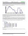
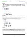

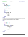
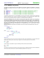
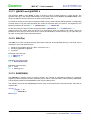
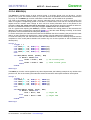

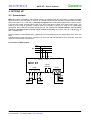
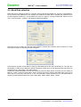
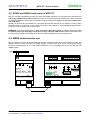
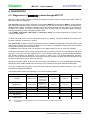
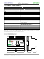
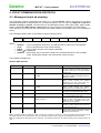


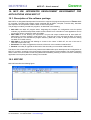
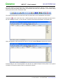
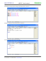
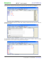
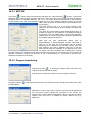

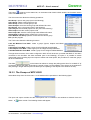
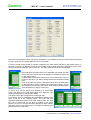


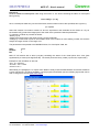


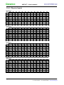
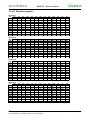
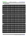


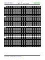

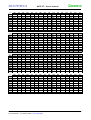


![[ Página intencionalmente en blanco ]](http://vs1.manualzilla.com/store/data/005979389_1-1ee088f8906d2dba9f81cb338c9eb94e-150x150.png)