1
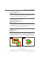
DIANA
Finite Element Analysis
User’s Manual
Getting Started
Release 9.3
TNO DIANA
BV
April 25, 2008
ii
DIANA – Finite Element Analysis
User’s Manual release 9.3
Getting Started
Edited by: Jonna Manie and Gerd-Jan Schreppers
Published by:
TNO DIANA bv
Schoemakerstraat 97, 2628 VK Delft, The Netherlands.
Phone: +31 15 27 63 250
Fax: +31 15 27 63 019
E-mail: info@tnodiana.com
Web page: www.tnodiana.com
Trademarks.
Diana is a registered trademark of TNO DIANA bv. FemGV, FemGen and FemView
are trademarks of Femsys Ltd. CADfix is a registered trademark of TranscenData Europe Limited. Windows is a registered trademark of Microsoft Corporation.
PostScript, Acrobat and Acrobat Reader are registered trademarks of Adobe Systems, Inc. AutoCAD is a registered trademark of Autodesk Inc. DXF is a trademark
of Autodesk Inc. ACIS is a registered trademark of Spatial Technology Inc. CADDS
and Pro/ENGINEER are registered trademarks of Parametric Technology Corporation. CATIA is a registered trademark of Dassault Systemes S.A. IGES is a trademark
of IGES Data Analysis, Inc. Parasolid is a registerd trademark of UGS Corporation.
PATRAN is a registered trademark of MSC Software Corporation. The X Window
System is a trademark of M.I.T. unix is a registered trademark of UNIX Systems Laboratories, Inc. Intel is a registered trademark of Intel Corporation. SUN and Solaris
are trademarks or registered trademarks of Sun Microsystems, Inc. HP is a registered
trademark of Hewlett-Packard Company. All other brand names, product names or
trademarks belong to their respective holders.
First edition, April 25, 2008.
Copyright © 2008 by TNO DIANA bv, all rights reserved. No part of this publication
may be reproduced in any form by print, photoprint, microfilm or any other means,
without the prior written permission of the publisher.
The information in this document is subjected to change without notice and should
not be construed as a commitment by TNO DIANA bv. TNO DIANA bv assumes
no responsibility for any errors that may appear in this document.
The Diana system is the sole property of TNO DIANA bv. Software materials made
available are solely for use at a single site; they are not to be distributed to others
without prior written permission of TNO DIANA bv.
This document was prepared with the LATEX Document Preparation System.
April 25, 2008 – First ed.
Diana-9.3 User’s Manual – Getting Started
Contents at a Glance
Preface
vii
1 General Introduction
1
2 Graphical User Interface
9
3 Batch User Interface
43
4 Analysis of a Concrete Floor
55
A Notation and Conventions
77
B Running a Batch Analysis Job
97
C Available Element Types
109
D Background Information
115
Diana-9.3 User’s Manual – Getting Started
April 25, 2008 – First ed.
iv
April 25, 2008 – First ed.
Diana-9.3 User’s Manual – Getting Started
Contents
Preface
1 General Introduction
1.1 Field of Application . . . . . . . . .
1.1.1
Capabilities . . . . . . . . .
1.1.2
Analysis Types . . . . . . .
1.1.3
Material Models . . . . . .
1.1.4
Solvers . . . . . . . . . . .
1.2 Program Structure . . . . . . . . . .
1.2.1
Batch Interface . . . . . . .
1.2.2
Graphical User Interface .
1.2.3
User-supplied Subroutines .
ix
.
.
.
.
.
.
.
.
.
.
.
.
.
.
.
.
.
.
.
.
.
.
.
.
.
.
.
.
.
.
.
.
.
.
.
.
.
.
.
.
.
.
.
.
.
.
.
.
.
.
.
.
.
.
.
.
.
.
.
.
.
.
.
.
.
.
.
.
.
.
.
.
.
.
.
.
.
.
.
.
.
.
.
.
.
.
.
.
.
.
.
.
.
.
.
.
.
.
.
.
.
.
.
.
.
.
.
.
.
.
.
.
.
.
.
.
.
.
.
.
.
.
.
.
.
.
1
1
1
2
4
5
6
6
7
8
2 Graphical User Interface
2.1 Model of a Hexagonal Plate . . . . . . . .
2.2 Starting iDIANA . . . . . . . . . . . . . .
2.2.1
The Initial Working Window . .
2.3 Designing a Model . . . . . . . . . . . . .
2.3.1
Initiating a New Model . . . . .
2.3.2
The Working Window . . . . . .
2.3.3
Geometry Definition . . . . . . .
2.3.4
Creating a Set . . . . . . . . . .
2.3.5
Meshing Procedure . . . . . . .
2.3.6
Boundary Constraints . . . . . .
2.3.7
Loading Definition . . . . . . . .
2.3.8
Material and Physical Properties
2.3.9
Running a Command File . . . .
2.3.10 Saving the Current Model . . . .
2.4 Performing the Analysis . . . . . . . . . .
2.4.1
Initiation . . . . . . . . . . . . .
2.4.2
Analysis Options . . . . . . . . .
2.4.3
Calculation . . . . . . . . . . . .
2.5 Postprocessing . . . . . . . . . . . . . . .
.
.
.
.
.
.
.
.
.
.
.
.
.
.
.
.
.
.
.
.
.
.
.
.
.
.
.
.
.
.
.
.
.
.
.
.
.
.
.
.
.
.
.
.
.
.
.
.
.
.
.
.
.
.
.
.
.
.
.
.
.
.
.
.
.
.
.
.
.
.
.
.
.
.
.
.
.
.
.
.
.
.
.
.
.
.
.
.
.
.
.
.
.
.
.
.
.
.
.
.
.
.
.
.
.
.
.
.
.
.
.
.
.
.
.
.
.
.
.
.
.
.
.
.
.
.
.
.
.
.
.
.
.
.
.
.
.
.
.
.
.
.
.
.
.
.
.
.
.
.
.
.
.
.
.
.
.
.
.
.
.
.
.
.
.
.
.
.
.
.
.
.
.
.
.
.
.
.
.
.
.
.
.
.
.
.
.
.
.
.
.
.
.
.
.
.
.
.
.
.
.
.
.
.
.
.
.
.
.
.
.
.
.
.
.
.
.
.
.
.
.
.
.
.
.
.
.
.
.
.
.
.
.
.
.
.
.
.
.
.
.
.
.
.
.
.
.
9
9
10
10
11
12
13
14
22
23
25
26
27
30
30
31
31
33
36
36
Diana-9.3 User’s Manual – Getting Started
.
.
.
.
.
.
.
.
.
.
.
.
.
.
.
.
.
.
April 25, 2008 – First ed.
vi
CONTENTS
.
.
.
.
.
.
.
.
.
.
.
.
.
.
.
.
.
.
.
.
38
40
41
41
3 Batch User Interface
3.1 Input Data File . . . . . . . . . . . . . . . . . . . . . . .
3.1.1
Node Coordinates . . . . . . . . . . . . . . . . .
3.1.2
Elements . . . . . . . . . . . . . . . . . . . . . .
3.1.3
Material and Geometry Properties . . . . . . . .
3.1.4
Boundary Conditions . . . . . . . . . . . . . . .
3.1.5
Loading . . . . . . . . . . . . . . . . . . . . . . .
3.2 Performing the Analysis . . . . . . . . . . . . . . . . . . .
3.2.1
Analysis Commands . . . . . . . . . . . . . . . .
3.2.2
Running a Batch Analysis Job . . . . . . . . . .
3.2.3
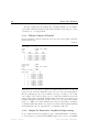
Tabular Output of Results . . . . . . . . . . . .
3.2.4
Output for Interactive Graphics Postprocessing .
.
.
.
.
.
.
.
.
.
.
.
.
.
.
.
.
.
.
.
.
.
.
.
.
.
.
.
.
.
.
.
.
.
.
.
.
.
.
.
.
.
.
.
.
43
44
46
47
48
49
49
50
50
51
52
52
4 Analysis of a Concrete Floor
4.1 Finite Element Model . . . . . . . . . . .
4.2 Preprocessing . . . . . . . . . . . . . . . .
4.2.1
Geometry Definition . . . . . . .
4.2.2
Meshing . . . . . . . . . . . . . .
4.2.3
Boundary Constraints . . . . . .
4.2.4
Some More Sets . . . . . . . . .
4.2.5
Material and Physical Properties
4.2.6
Loads . . . . . . . . . . . . . . .
4.3 Performing the Analysis . . . . . . . . . .
4.3.1
Analysis Options . . . . . . . . .
4.3.2
Running the Analysis Job . . . .
4.4 Postprocessing . . . . . . . . . . . . . . .
4.4.1
Displacements . . . . . . . . . .
4.4.2
Load Combination . . . . . . . .
4.4.3
Support Reactions . . . . . . . .
4.4.4
Bending Moments . . . . . . . .
4.4.5
Moment Diagrams for Beam . .
4.4.6
Leaving iDIANA . . . . . . . . .
.
.
.
.
.
.
.
.
.
.
.
.
.
.
.
.
.
.
.
.
.
.
.
.
.
.
.
.
.
.
.
.
.
.
.
.
.
.
.
.
.
.
.
.
.
.
.
.
.
.
.
.
.
.
.
.
.
.
.
.
.
.
.
.
.
.
.
.
.
.
.
.
.
.
.
.
.
.
.
.
.
.
.
.
.
.
.
.
.
.
.
.
.
.
.
.
.
.
.
.
.
.
.
.
.
.
.
.
.
.
.
.
.
.
.
.
.
.
.
.
.
.
.
.
.
.
.
.
.
.
.
.
.
.
.
.
.
.
.
.
.
.
.
.
.
.
.
.
.
.
.
.
.
.
.
.
.
.
.
.
.
.
.
.
.
.
.
.
.
.
.
.
.
.
.
.
.
.
.
.
.
.
.
.
.
.
.
.
.
.
.
.
.
.
.
.
.
.
.
.
.
.
.
.
.
.
.
.
.
.
.
.
.
.
.
.
.
.
.
.
.
.
.
.
.
.
.
.
.
.
.
.
.
.
55
55
55
56
59
61
63
63
64
65
66
67
67
68
71
72
73
74
76
A Notation and Conventions
A.1 General Aspects . . . . . . . . . . .
A.1.1
Fonts . . . . . . . . . . . .
A.1.2
References . . . . . . . . .
A.1.3
Data Types . . . . . . . . .
A.1.4
Syntax Description . . . .
A.1.5
Series of Numerical Values
.
.
.
.
.
.
.
.
.
.
.
.
.
.
.
.
.
.
.
.
.
.
.
.
.
.
.
.
.
.
.
.
.
.
.
.
.
.
.
.
.
.
.
.
.
.
.
.
.
.
.
.
.
.
.
.
.
.
.
.
.
.
.
.
.
.
.
.
.
.
.
.
.
.
.
.
.
.
77
77
77
78
78
79
79
2.6
April 25, 2008 – First ed.
2.5.1
2.5.2
2.5.3
Leaving
Displacements . .
Bending Moments
Support Reactions
Interactive DIANA
.
.
.
.
.
.
.
.
.
.
.
.
.
.
.
.
.
.
.
.
.
.
.
.
.
.
.
.
.
.
.
.
.
.
.
.
.
.
.
.
.
.
.
.
.
.
.
.
.
.
.
.
.
.
.
.
.
.
.
.
.
.
.
.
.
.
.
.
.
.
.
.
.
.
.
.
.
.
.
.
.
.
Diana-9.3 User’s Manual – Getting Started
CONTENTS
A.2
A.3
vii
A.1.6
Presentation of Syntax and Examples
Batch Input Data Format . . . . . . . . . . . .
A.2.1
Title . . . . . . . . . . . . . . . . . .
A.2.2
Tables . . . . . . . . . . . . . . . . . .
A.2.3
Fields and Data . . . . . . . . . . . .
A.2.4
Comment and Blank Lines . . . . . .
A.2.5
Examples . . . . . . . . . . . . . . . .
Batch Command Language . . . . . . . . . . .
A.3.1
Keywords . . . . . . . . . . . . . . . .
A.3.2
Data Items . . . . . . . . . . . . . . .
A.3.3
Parameters . . . . . . . . . . . . . . .
A.3.4
Module and Control Commands . . .
A.3.5
Continuation of Commands . . . . . .
A.3.6
Command Blocks . . . . . . . . . . .
A.3.7
Comment and Blank Lines . . . . . .
A.3.8
Example . . . . . . . . . . . . . . . .
B Running a Batch Analysis Job
B.1 Running DIANA . . . . . . . . . . . .
B.1.1
Files . . . . . . . . . . . . . .
B.1.2
Running a Job . . . . . . . .
B.1.3
Error Messages . . . . . . . .
B.1.4
Job Logging . . . . . . . . .
B.1.5
Running Under UNIX . . . .
B.1.6
Running Under MS-Windows
.
.
.
.
.
.
.
.
.
.
.
.
.
.
.
.
.
.
.
.
.
.
.
.
.
.
.
.
.
.
.
.
.
.
.
.
.
.
.
.
.
.
.
.
.
.
.
.
.
.
.
.
.
.
.
.
.
.
.
.
.
.
.
.
.
.
.
.
.
.
.
.
.
.
.
.
.
.
.
.
.
.
.
.
.
.
.
.
.
.
.
.
.
.
.
.
.
.
.
.
.
.
.
.
.
.
.
.
.
.
.
.
.
.
.
.
.
.
.
.
.
.
.
.
.
.
.
.
.
.
.
.
.
.
.
.
.
.
.
.
.
.
.
.
.
.
.
.
.
.
.
.
.
.
.
.
.
.
.
.
.
.
.
.
.
.
.
.
.
.
.
.
.
.
.
.
.
.
.
.
.
.
.
.
.
.
.
.
.
.
.
.
.
.
.
80
85
85
85
86
88
89
92
92
92
92
92
93
94
95
95
.
.
.
.
.
.
.
.
.
.
.
.
.
.
.
.
.
.
.
.
.
.
.
.
.
.
.
.
.
.
.
.
.
.
.
.
.
.
.
.
.
.
.
.
.
.
.
.
.
.
.
.
.
.
.
.
.
.
.
.
.
.
.
.
.
.
.
.
.
.
97
97
97
98
100
103
104
107
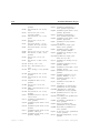
C Available Element Types
D Background Information
D.1 Organization around DIANA
D.2 Reporting a Problem . . . .
D.3 Quality Assurance . . . . . .
D.4 Historical Notes . . . . . . .
109
.
.
.
.
.
.
.
.
.
.
.
.
.
.
.
.
.
.
.
.
.
.
.
.
.
.
.
.
.
.
.
.
.
.
.
.
.
.
.
.
.
.
.
.
.
.
.
.
.
.
.
.
.
.
.
.
.
.
.
.
.
.
.
.
.
.
.
.
.
.
.
.
.
.
.
.
.
.
.
.
115
115
116
116
118
Bibliography
125
Index
127
Diana-9.3 User’s Manual – Getting Started
April 25, 2008 – First ed.
viii
April 25, 2008 – First ed.
CONTENTS
Diana-9.3 User’s Manual – Getting Started
Preface
This volume of the Diana User’s Manual introduces the novice user to the
Diana Finite Element Analysis code. Moreover it formally describes things like
convention of notation in the User’s Manual, how to run an analysis job etc.
Novice user’s are advised to read the chapters of this volume sequentially
with Diana at hand, installed on a familiar computer system. Doing so will
give a general insight in the capabilities and user interfaces of Diana, a basis for
more specific subjects in other volumes. The User’s Manual for the Diana-9.3
release comprises the following volumes.
Getting Started (this volume), gives a general overview of various aspects of
the Diana finite element code. Introduces the Diana batch interface and
the iDiana interactive graphics interface to the novice user.
Analysis Procedures, describes the various analysis procedures. Specifies the
appropriate input data and user commands for the Diana batch interface.
Element Library, describes the various finite elements. Specifies the appropriate input data like connectivity and loading for the Diana batch interface.
Material Library, describes the various material models. Specifies the appropriate input data for the Diana batch interface.
Pre- and Postprocessing, the reference manual for the iDiana interactive
graphics interface.
FX+ for DIANA, is a tutorial introduction to the combined use of the FX+
pre- and postprocessor and Diana.
Analysis Examples, presents examples of various types of finite element analysis, performed on a wide range of finite element models. Includes tutorial
examples of the iDiana Pre- and Postprocessing interactive graphics interface.
Concrete and Masonry Analysis, describes and illustrates the application
of Diana for analysis of concrete and masonry models.
Diana-9.3 User’s Manual – Getting Started
April 25, 2008 – First ed.
x
Preface
Geotechnical Analysis, describes and illustrates the application of Diana
for geotechnical analysis like ‘Soil–Pore Fluid Analysis’ and ‘Liquefaction
Analysis’.
Application Modules, describes and illustrates the Diana modules for special applications like ‘Parameter Estimation’ and ‘Lattice Analysis’.
Cumulative Index, very helpful if you don’t know where to search in the
User’s Manual for a particular subject.
Cautionary note. Throughout this manual, it will be assumed that the
reader has a basic understanding of applied mechanics and the Finite Element
Method in general.1 Also some experience with use of computers and computer
programs is assumed.
1 Very
informative introductions are the “Guidelines to Finite Element Practice” [10] and
the book “A Finite Element Primer” [11], both published by NAFEMS.
April 25, 2008 – First ed.
Diana-9.3 User’s Manual – Getting Started
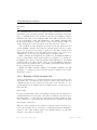
Chapter 1
General Introduction
Diana is a general purpose finite element code, based on the Displacement
Method.1 It has been under development at TNO since 1972. In the beginning of 2003 a new organisation around Diana was founded: TNO DIANA bv.
This chapter is a general introduction to the use of the Diana Finite Element
Code. The first section gives a short overview of the field of application [§ 1.1].
The second section introduces Diana’s program structure and the various user
interfaces [§ 1.2].
1.1
Field of Application
Diana is a multi-purpose finite element program (three-dimensional and nonlinear) with extensive material, element and procedure libraries based on advanced
database techniques. Developed by civil engineers from a civil engineering perspective, Diana’s most appealing capabilities are in the fields of concrete and
soil. Worldwide, engineering consultants apply Diana to their work on bridge
design, dams, offshore platforms, road and rail design, and tunneling. After
the Kobe earthquake, many Japanese Diana users turned their attention to
Diana’s power in dynamic loading analysis as well. Furthermore, Diana is
extensively used for research and analysis purposes at technical universities on
every continent.
1.1.1
Capabilities
Civil, mechanical, biomechanical, and other engineering problems can be solved
with the Diana program. Standard Diana application work includes: concrete
cracking, excavations, tunneling, composites, plasticity, creep, cooling of concrete, engineering plastics, various rubbers, groundwater flow, fluid–structure
1 DIANA
= DIsplacement method ANAlyser.
Diana-9.3 User’s Manual – Getting Started
April 25, 2008 – First ed.
2
General Introduction
interactions, temperature-dependent material behavior, heat conduction, stability analysis, buckling, phased analysis, et cetera.
Diana offers a great variety of elements (see Appendix C), such as beams
(straight and curved), solids, membranes, axisymmetric and plane strain elements, plates, shells, springs, and interface elements (gap). All these elements
may be combined in a particular finite element model. Moreover, special elements may be used to model embedded reinforcement in concrete structures:
bars, grids and prestressed cables. To model these reinforcements Diana has
a built-in preprocessor in which reinforcement can be defined globally. Volume
Element Library gives a complete overview of the available element types.
Diana offers a variety of advantages over other commercially available FEM
software. One of the most notable benefits is its power in the field of concrete
and soil where excellent material models are available, developed by researchers
in the Netherlands since the early 1970’s. Most notably are the models for
smeared and discrete cracking, and for reduction of prestress due to special
effects. Diana also offers unique analysis capabilities in Parameter Estimation
and Lattice analysis. In addition, Diana can do various types of dynamic
analysis important in earthquake engineering.
1.1.2
Analysis Types
With Diana you can choose from a wide range of analysis types, all extensively
described in Volume Analysis Procedures. Here we give a short overview.
Linear static analysis. The Linear Static module provides a solid base for
the Diana finite element program. We mention some of the most important
features. Linear constraints (tyings) can be specified to model linear dependencies between degrees of freedom of the system of equations (displacements,
rotations, temperatures etc.). Moving loads can be applied to determine influence lines and fields for critical result items. Fatigue failure analysis can be
performed using standard Wöhler diagrams.
Nonlinear analysis. Diana’s strongest points lie in its nonlinear capabilities.
For physical nonlinear analysis various material models are available including
plasticity, viscoplasticity, cracking, viscoelasticity, creep, hyperelasticity, liquefaction of soil and many more [§ 1.1.3]. Time dependent development of temperature, concentration and maturity can be specified.
For geometrical nonlinear analysis the Total and Updated Lagrange methods
are available Moreover, contact analysis can be performed to check whether
contact occurs in user-specified possible contact zones in the model.
Dynamic analysis. All appropriate types of dynamic structural analysis may
be performed with Diana: steady-state harmonic modal and direct frequency
response analysis, spectral response analysis, hybrid frequency time domain
April 25, 2008 – First ed.
Diana-9.3 User’s Manual – Getting Started
1.1 Field of Application
3
analysis, linear and nonlinear transient analysis, and fluid–structure interaction
analysis.
Euler stability analysis. Euler stability analysis gives information about
‘linearized stability’ of a structure and provides a relatively simple and effective
method to get a fair impression of a structure’s buckling modes. The Euler
stability analysis may be followed by a perturbation analysis to investigate the
postbuckling behavior. The postbuckling displacement field is solved by applying a continuation analysis using a stepwise generalized Newton–Raphson
scheme.
Potential flow analysis. A potential flow analysis may be employed to solve
general one-potential convection–diffusion problems. It can be used in the following application fields: heat flow, detailed and regional groundwater flow,
beam cross-section analysis, fluid–structure interaction, and Reynolds flow or
lubrication. The heat flow module includes special features to perform advanced potential flow analysis. For instance, hydration heat and cooling pipe
elements can be used to study the thermal behavior of cement-based materials at early ages. The solidification and evaporation process within a liquid
can also be modeled. Groundwater flow analysis also benefits from advanced
features such as the modeling of seepage faces or study of the contamination
transport of a pollutant within a soil.
Coupled flow–stress analysis. In coupled flow–stress analysis the interaction may be two- or one-directional. You may use a mixture analysis with mixture elements for two-directional interaction problems, for example a geotechnical transient consolidation analysis. A staggered analysis can be performed
to solve one-directional interaction problems like geotechnical (static) stability
analysis or structural analysis with thermal load.
Phased analysis. Diana enables modeling of phased construction. It determines the effects of construction history and shows the critical construction
stages. Phased analysis can be performed on a structural level and on a potential
flow level.
Parameter estimation. Parameter estimation may be used to determine
non-shape parameters by minimizing the differences between calculated and
target displacements. The confrontation of target displacement field data with
calculated field data leads to a quantitative determination of the unknown parameters. The parameters may comprise material properties, geometric properties (like the thickness of a plate), and load factors within combinations of load
cases.
Diana-9.3 User’s Manual – Getting Started
April 25, 2008 – First ed.
4
General Introduction
Lattice analysis. Diana offers a special module for analysis with the Delft
lattice model. This is a discrete material model where the continuum is replaced
by an equivalent beam or truss structure, the lattice. The main purpose of the
lattice model is to achieve understanding of the fracture processes which occur
at small scales and the influence of the micro-structural disorder on the global
behavior of the material.
1.1.3
Material Models
Diana offers a wide variety of material models which can be applied in the
various analysis types. All material models are extensively described in Volume Material Library. As an introduction, we present a summary of the most
important models.
Elasticity. For linear structural analysis the simple iso- and orthotropic elasticity models are available. Within nonlinear analysis there are three applications for an elastic material model: ambient influence (temperature, concentration, maturity and time), nonlinear elasticity to set a unique nonlinear relation
between stress and strain, and modified elasticity which modifies the elasticity
parameters during the analysis.
Nonlinear elasticity is typically applied for granular materials, for which
Diana offers two models: the standard Grains model and the model according
to Boyce for granular materials under repeated loading. Modified elasticity is
particularly relevant for soil mechanics, for instance to modify Poisson’s ratio
and Young’s modulus after having set the long term (drained) initial soil stresses.
For rubbery materials, Diana offers hyperelasticity models which can handle
large strains and large deformations. The Mooney–Rivlin, and Besseling models
are available to define the deviatoric part of the strain energy function. The
hydrostatic part may be described with an incompressibility model, or with a
linear or nonlinear compressibility model.
In the material library the regular models for plasticity are available: Tresca,
Von Mises, Mohr–Coulomb, and Drucker–Prager. To handle combined tension
and compression for concrete plasticity, Diana offers the Rankine principal
stress model, stand-alone or in combination with Von Mises or Drucker–Prager.
For clay-like materials there is the Egg Cam-clay model and for sand-like
materials the Modified Mohr–Coulomb model. For orthotropic plasticity the
models of Hill and Hoffmann are available. For rock-like materials the model
of Hoek–Brown as available. To incorporate viscous effects in plastic behavior,
Diana offers the viscoplastic models of Perzyna and Duvaut–Lions.
Another plasticity special is the Fraction model which may be used for plasticity and metal creep analyses. It splits the material into a number of fractions,
each of them having its own plasticity and creep parameters.
Cracking. Various so-called smeared cracking models are available to simulate cracking of brittle materials like concrete. Basically these models are
April 25, 2008 – First ed.
Diana-9.3 User’s Manual – Getting Started
1.1 Field of Application
5
a combination of tension cut-off, tension softening and shear retention criteria. A rate-dependent cracking criterion can be added optionally. The smeared
cracking models can also be specified with ambient influence, i.e., dependent of
temperature, concentration or maturity.
In addition to the smeared cracking models, two constitutive models based
on total strain are available: the fixed and the strain rotating concept. These
models describe the cracking and crushing behavior of the material with a nonlinear elasticity relationship. The total strain models are very well suited for
Serviceability Limit State (SLS) and Ultimate Limit State (ULS) analyses.
Viscoelasticity. Viscoelasticity can be applied via a Maxwell Chain model
for the relaxation function and a Kelvin Chain model or the Double Power law
for the creep function. Built-in creep models are available for some model codes
for concrete: the European CEB-FIP model code 1990, the Dutch NEN 6720
code and the American ACI code 209.
Soil specials. Especially for nonlinear soil mechanics you may specify the
initial stress ratio. Moreover, the undrained behavior can be specified via the
excess pore fluid pressure.
Three dedicated constitutive models are available to analyze the liquefaction
of soil subjected to seismic loading: the Towhata-Iai model for two-dimensional
undrained analysis, the Bowl model for partly drained conditions with predominantly horizontal shearing, and the Nishi model for partly drained conditions
with an arbitrary shearing direction.
Interface nonlinearities. For interface elements, you may specify a nonlinear relation between tractions (stresses) and relative displacements across the
interface. To simulate the interface behavior, various models are available: discrete cracking, crack dilatancy, bond-slip, friction, nonlinear elasticity, and a
general user-supplied interface model.
User-supplied material model. On top of all the built-in material models,
Diana offers the user-supplied subroutine mechanism to let you specify a general
nonlinear material behavior.
1.1.4
Solvers
Diana offers various solution procedures which are needed to solve the system
of equations of a finite element model. For a complete description see Volume
Analysis Procedures.
Linear equations. Diana can solve the linear system of equations either
direct or iteratively. Two direct methods are available: a Sparse Cholesky
decomposition method, and an out-of-core Gauss decomposition method. On
Diana-9.3 User’s Manual – Getting Started
April 25, 2008 – First ed.
6
General Introduction
Intel based Windows and Linux platforms a third method is available: the Intel
PARDISO solution method, i.e. a parallel direct sparse solver. The Sparse
Cholesky method is the default and will do in most cases. By default both
direct solution methods are applied in combination with an automatic optimal
ordering procedure.
An iterative method is available to solve the linear system of equations. The
preconditioning process can be customized: you may specify the parameters for
two types of preconditioning: Incomplete LU-decomposition or Diagonal.
Nonlinear equations. In a nonlinear analysis, the nonlinear system of equations must be solved iteratively until equilibrium has been reached. Therefore
Diana offers the well-known iteration schemes: Constant and Linear Stiffness,
Regular and Modified Newton–Raphson. Moreover three Quasi-Newton methods are available: Broyden, BFGS, and Crisfield.
All iteration schemes may be combined with Arc-length control methods to
adapt the loading during iterations in one load step, you may choose the the
Spherical Path or the Updated Normal Plane method. An Indirect Displacement
control option is available to cope with problems like snap-through and snapback behavior. To stabilize the convergence or increase its speed, a Line Search
algorithm may be applied.
Eigenvalues. Depending in the type of element matrices to be applied, an
eigenvalue analysis with Diana may be performed to get the free vibration
frequencies and eigenmodes, to solve the standard eigenproblem, or for linearized
buckling analysis.
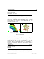
1.2
Program Structure
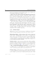
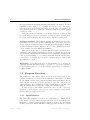
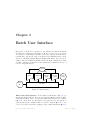
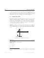
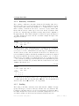
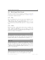
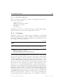
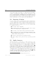
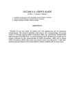
The architecture of the Diana system, as seen from the user’s point of view
consists of a number of modules, indicated with M1 to Mn in Figure 1.1. Each
module fulfills a clearly defined task in the Finite Element Analysis. For instance, Module input (M1 ) reads the description of the finite element model.
All modules have data communication with a central database, the filos file.
After the analysis Diana can produce output of the analysis results.
To have access to this software architecture, there are three basic userinterfaces: a batch interface, an interactive graphical interface (gui), and an
interface with user-supplied subroutines.
1.2.1
Batch Interface
The dashed lines in Figure 1.1 indicate the batch interface to Diana. In the
batch interface the user defines the finite element model via an input data file.
Furthermore, analysis commands must be supplied to indicate how the analysis
should be performed. Diana will then load the appropriate modules to perform
April 25, 2008 – First ed.
Diana-9.3 User’s Manual – Getting Started
1.2 Program Structure
7
batch
batch
User
Pre
database
iDiana
(gui)
input
commands
Post
database
Tabular
output
Diana
M1
M2
...
Mn
batch
(analysis)
Filos
file
Figure 1.1: Diana program architecture
the analysis. Output can be obtained in tabular form for printing or viewing.
See Chapter 3 for a comprehensive introduction to Diana’s batch interface.
1.2.2
Graphical User Interface
The interactive graphics interface, called iDiana, is a fully integrated pre- and
postprocessing environment to Diana [Fig. 1.1]. With iDiana you specify the
basic model geometry, loading, materials and other data interactively. This data
is stored in a database for preprocessing from which iDiana can automatically
generate the finite element model in the form of the input data file. Moreover,
the necessary analysis commands may be generated via user-friendly interactive
forms. Analysis results are written to a database for interactive postprocessing
and may then be presented in various styles like colored contour plots, diagrams,
tables etc. See Chapter 2 for an introduction to Diana’s interactive Graphical
User Interface.
Diana-9.3 User’s Manual – Getting Started
April 25, 2008 – First ed.
8
General Introduction
1.2.3
User-supplied Subroutines
Diana offers a user-supplied subroutine option to the advanced user, with skill
in programming. Via this option the code of various subroutines with predefined arguments may be supplied to define special material models, interface
behavior and the like.
April 25, 2008 – First ed.
Diana-9.3 User’s Manual – Getting Started
Chapter 2
Graphical User Interface
This chapter introduces the interactive graphical user interface to the Diana
finite element analysis capabilities, also known as iDiana.1 First we will outline
how to start up iDiana and introduce its basic look-and-feel [§ 2.2]. Then we
will demonstrate how to build a finite element model in the Design environment
[§ 2.3]. To perform the actual finite element analysis of the model iDiana offers
an interactive interface to the batch analysis commands which we will briefly
demonstrate [§ 2.4]. Then we will show some basic features of the Results environment where we may display the analysis results in various styles [§ 2.5].
Finally we will show how to leave iDiana [§ 2.6].
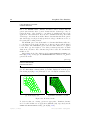
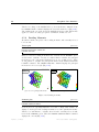
2.1
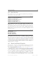
Model of a Hexagonal Plate
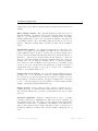
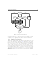
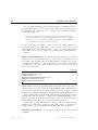
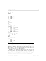
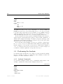
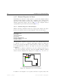
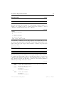
As an introduction to iDiana we will demonstrate the linear elastic analysis of
a plate as shown in Figure 2.1 on the following page. The outer edge of the plate
is a regular hexagon with corners on a circle with radius ro = 10 m. Concentric
with the outer edge, the plate has a circular hole with a radius ri = 4 m. The
plate is vertically supported (uZ = 0) at each of the corners along the outer
edge.
Properties. We assume that the plate is made of concrete with a Young’s
modulus E = 22000 MPa, a Poisson’s ratio ν = 0.2, and a mass density ρ = 2400
kg/m3 . The thickness of the plate is t = 0.30 m. The loading consists of the
dead weight and of a vertical load qZ = −20 kN/m uniformly distributed along
the edge of the circular hole.
Finite element model. Due to symmetry of the geometry, the supports and
the loading it is sufficient to model and analyze only one quarter of the plate,
1 For
a formal reference of iDiana’s facilities see Volume Pre- and Postprocessing.
Diana-9.3 User’s Manual – Getting Started
April 25, 2008 – First ed.
10
Graphical User Interface
Y
uZ = 0
ri = 4 m
ro = 10 m
t = 0.30 m
t
qZ = −20 kN/m1
qZ
X
ri
E = 22000 MPa
ν = 0.2
ρ = 2400 kg/m3
ro
Figure 2.1: Model of hexagonal plate
provided that we impose appropriate boundary conditions along the symmetry
lines. Furthermore we may choose regular plate bending elements because there
is neither in-plane loading nor in-plane deformation, otherwise shell elements
would have been required. In this case we will apply eight-node quadrilateral
CQ24P elements.2
2.2
Starting iDIANA
If iDiana has been installed properly on your computer, you may start an
interactive session by typing idiana or by clicking the appropriate icon on the
desktop.3
2.2.1
The Initial Working Window
Initially iDiana brings you in the Index working environment where the various
models are recorded. In this environment you have to tell iDiana whether
you are going to build a model in the Design environment or to examine the
analysis results of a model in the Results environment. In this example we start
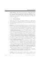
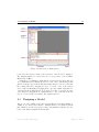
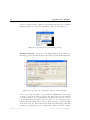
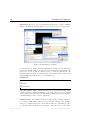
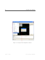
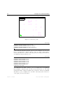
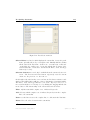
with building a new model like outlined in the next section. In the window
of the Index environment you may recognize various areas, also called widgets,
and opportunities to manipulate these [Fig. 2.2]. The large gray square is the
2 See Appendix C for an overview of Diana element types and Volume Element Library
for comprehensive description.
3 The illustrations in this chapter, and in all other example descriptions in the Diana User’s
Manual, only serve as signs of recognition. For a good understanding of the discussions we
suggest that you perform the commands in a real-life interactive iDiana session.
April 25, 2008 – First ed.
Diana-9.3 User’s Manual – Getting Started
2.3 Designing a Model
11
Figure 2.2: Interactive working window
location for the Graphics Window where pictures of the model are displayed.
The Graphics Window becomes active as soon as you have opened a Finite
Element Model [§ 2.3].
Basically you communicate with iDiana via menu’s in the Menu Bar and
via commands in the Command Browser tree view control. Any messages that
iDiana would give appear in the Tabular Output widget below. You can resize
the working window by dragging its edges or corners. Some of the widgets
can be resized individually by dragging their edges. By default, all widgets are
docked inside the working window. You can move around, or even undock, some
of the widgets by dragging their docking handles, i.e., the double line at the left
side. To redock a widget you must double click its title bar.
2.3
Designing a Model
The process of the definition of a new model typically involves tasks as initiation,
definition of geometry and boundary conditions and more. We will now discuss
this definition, also known as preprocessing, and simultaneously introduce the
basics of the iDiana Graphical User Interface.
Diana-9.3 User’s Manual – Getting Started
April 25, 2008 – First ed.
12
Graphical User Interface
2.3.1
Initiating a New Model
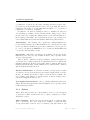
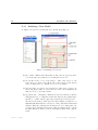
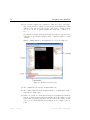
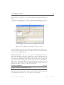
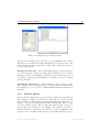
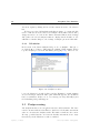
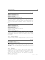
To initiate a new model you must take the following steps [Fig. 2.3].
Figure 2.3: Initiating a new model
(1) Choose File → New from the Menu Bar. A dialog New now pops up where
you can specify some parameters to identify the new model.
(2) Use the file browser on top of the dialog to define, and/or move to, the
folder where you want to keep all the data of the new model, also known
as the ‘working directory’. In this case we choose C:/Diana.
(3) Type the name of a new model. You may type either lower or upper case
letters but iDiana will not consider the case of the text as significant. In
this case we choose the name PLATE.
(4) Specify the type of analysis for which the new model is intended. iDiana
will apply the type to adapt lists, menus and dialogs in the graphical user
interface to contain only the appropriate element types and properties
The list box shows the possible types. For this example you must choose
Structural 3D which indicates a model for a three-dimensional structural
analysis. Why three-dimensional? In this model of a bending plate, the
geometry is two-dimensional but the loading and displacement occurs in
the third dimension. Therefore the model is characterized as three-dimensional.
April 25, 2008 – First ed.
Diana-9.3 User’s Manual – Getting Started
2.3 Designing a Model
13
(5) Click the Units button to open the Units Definition field. Here you may
check or indicate the units in which the model data will be specified. By
default Diana assumes SI-units which is OK for this example. Note the
NONE unit for ‘force’, because specification of units for both ‘mass’ and
‘force’ is ambiguous.
(6) Finally click the Create button to start the creation of the new model.
The New dialog disappears and the working window adapts its layout for
the Design environment.
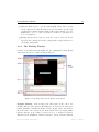
2.3.2
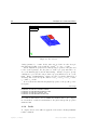
The Working Window
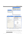
Compared to the Index environment [Fig. 2.2], the working window in the Design
environment shows some additional widgets [Fig. 2.4].
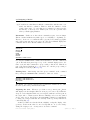
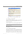
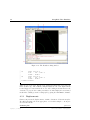
Figure 2.4: Working window in the Design environment
Graphics Window. Most notably is the black square in the center: the
Graphics Window. Here iDiana will display the model and some basic information. Initially it comprises the Monitor and the display of Axes. The Monitor
shows the name of the current model: ‘Model: PLATE’. The text ‘Analysis: DIANA’
indicates that the preprocessing concerns a model to be analyzed by Diana.
This involves the assignment of Diana elements to generic elements of iDiana
Diana-9.3 User’s Manual – Getting Started
April 25, 2008 – First ed.
14
Graphical User Interface
according to the chosen model type. For a new model, the Graphics Window
initially shows an XY Z coordinate axis system with the X and Y model axes
respectively horizontally and vertically in the viewing plane.
As the iDiana Graphical User Interface is based on the OpenGL standard
[12] you can interactively manipulate the model. Press and hold down the ctrl
key and then drag the mouse cursor while holding one of the mouse buttons
down:
Left – to rotate the model.
Middle – to zoom in and out.
Right – to translate the model in the Graphics Window.
Command Browser. The Command Browser now shows the top-level commands appropriate for the Design environment. The colored squares in front
of a keyword indicate its status in the command. A blue square marks a
keyword with a mandatory submenu. A red square marks a keyword with
an optional submenu. A green square marks a keyword which is the end of a
command.
Command Input. Any command that you give via the Command Browser
will be displayed in the Command Input line. The command prompt FG>
indicates that you are in the Design environment. You may also type a command
directly in the Command Input and then press the enter key to submit it to
iDiana for processing.
Tool Bar. The Tool Bar becomes enabled with tool buttons as a short-cut for
some commands, particularly to manipulate the picture. If you leave the cursor
on the button for a while, without clicking, the button’s meaning will show up.
2.3.3
Geometry Definition
We will now discuss the building of the model for the example of Figure 2.1 on
page 10. The first thing to do is define the geometry of the model via so-called
geometric parts: points, lines, surfaces, and bodies. Typically, points are defined
by their coordinates, lines by their end points, surfaces by their bounding lines,
and bodies by their bounding surfaces. For the plate in this example we will not
apply bodies because there are no solid elements. The points in the geometry of
this model are the vertices along the outline of the quarter plate. Naturally we
could compute their coordinates and directly input them. However, it is more
convenient to let iDiana determine the points from the basic dimensions of this
plate: the radii of the inner and circumscribed circles.
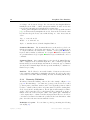
Definition of a point.
actions [Fig. 2.5].
April 25, 2008 – First ed.
You can define a point by performing the following
Diana-9.3 User’s Manual – Getting Started
2.3 Designing a Model
15
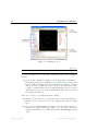
Figure 2.5: Issuing a command to define a point
(1) Click the Command Echo tab to activate the echoing of commands that
you are about to issue. This it not strictly necessary, however it is very
convenient to see the commands being echoed when iDiana executes them.
(2) The basic command to define any geometric part is GEOMETRY. When you
+ in front of the GEOMETRY keyword in the Command Browser
click the the command tree opens itself. The open branch shows the keywords of
the options for the GEOMETRY command. These keywords define various
geometric parts, for instance POINT to define a point, and LINE to define a
line.
(3) Click the POINT keyword to indicate that you are going to define a point.
The command now appears on the command line.
Alternatively to steps 2 and 3 you may type the command directly on the
command line. To simplify the typing of commands you may abbreviate
them. iDiana only requires that you type as many characters needed to
prevent ambiguity. In this case it would have been sufficient to type G P
instead of GEOMETRY POINT.4 Direct typing of abbreviated commands is
particularly useful if you are an experienced user.
4 The
Diana User’s Manual always shows the complete command.
Diana-9.3 User’s Manual – Getting Started
April 25, 2008 – First ed.
16
Graphical User Interface
(4) Now you may complete the command to define the center of the plate.
Type a name PC and coordinates 0 0 and then press the return key. This
defines a point called PC located at the origin of the coordinate system:
X = 0, Y = 0, Z = 0. iDiana assumes the omitted Z coordinate to be
zero.
Note that the decimal point in specified numerical values is optional. Large
values may be specified in scientific format, for instance 2.25E4 for a value
of 22500.
iDiana confirms that the point PC has indeed been created [Fig. 2.6].
Figure 2.6: Echoing a defined point
(5) The command is echoed in the Command Echo tab.
(6) The point is displayed in the Graphics Window: a small square with a
name label, both in yellow.
+ markers
(7) When you open the tree in the Model Navigator by clicking the in front of PLATE, Geometry and Points, iDiana shows the number of currently defined points in parentheses and also a list of their names. In this
case we see (1) and PC which indicates that the model comprises only one
point.
April 25, 2008 – First ed.
Diana-9.3 User’s Manual – Getting Started
2.3 Designing a Model
17
(8) You will notice that iDiana refills the command line with the same command, but without coordinates. This is to make the definition of additional points easier. To erase this preset command you may press the
escape key on the keyboard. This key also serves as a general eraser
when you make typing mistakes.
Intermezzo. Until now we have shown commands as part of screen-dumps.
This is a rather inefficient way with respect to readability, book printing etc.
Therefore, from now on commands will be presented in normal typographic
style, with a sans serif upper case type font. The User’s Manual displays the
commands that we have discussed until now as follows.
plate.fgc
FEMGEN PLATE
STRUCT 3D
METER
KILOGRAM
NONE
SECOND
KELVIN
GEOMETRY POINT PC 0. 0.
Note that the FEMGEN PLATE command is an alternative to the File → New menu
option. The indication plate.fgc on top of the command display refers to the
name of the file with commands for preprocessing of this model. This file is
part of the Diana distribution, so you can use it to run the preprocessing of
this example in a batch job [§ 2.3.9 p. 30].
Defining lines. After having erased the preset command on the command
line you may give GEOMETRY LINE commands to define two circles.
plate.fgc
GEOMETRY LINE CIRCLE PC 4
GEOMETRY LINE CIRCLE PC 10
EYE FRAME
The CIRCLE option indicates that the line is a full circle. In this case we define
the circle by its center point PC and its radius.
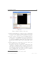
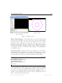
Adjusting the view. Whenever you define a new geometric part, iDiana
will display it in the Graphics Window at its proper location. By default the
viewport on the Graphics Window is a 1×1 square, with its lower-left point at
the origin of the coordinate system. Therefore initially you don’t see the defined
circles on the screen. By means of the EYE FRAME command you ask iDiana
to change the viewport such that the currently defined geometry will fit in it
comfortably [Fig. 2.7].
At first you will notice that the Monitor slightly overlaps the display of the
geometry. As the monitor has become a bit superfluous – it does not change
during the design process – we may remove it via the command
Diana-9.3 User’s Manual – Getting Started
April 25, 2008 – First ed.
18
Graphical User Interface
Figure 2.7: Adjusting the view
plate.fgc
DRAWING CONTENTS MONITOR OFF
We will demonstrate how to issue this command directly via the Command
Browser.
+ signs in the command tree.
(9) Open the full command by clicking on the In the final branch under MONITOR a green square precedes the OFF
keyword. This means that the keyword terminates a command. You may
directly issue the command by double-clicking on the OFF keyword. The
complete command flickers in the Command Input line and is executed
immediately (note its echo in the Command Echo tab). The monitor has
now disappeared [Fig. 2.7].
There are a few more topics which adjust the display.
(10) Click the Update button to get an updated view of the Model Navigator.
In this case we see that the model now comprises nine points and eight
lines.
(11) To get a larger Graphics Window we may get rid of the Model Navigator.
Click the close button in its upper-right corner. You can get the Model
Navigator back whenever you want via the View → Model Navigator menu
entry.
April 25, 2008 – First ed.
Diana-9.3 User’s Manual – Getting Started
2.3 Designing a Model
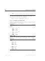
19
iDIANA 9.2-08 : TNO Diana BV
11 MAR 2008 09:29:55 geom1.ps
Model: PLATE
Analysis: DIANA
Model Type: Structural 3D
P6
L6
L5
P2
L2
L1
P7
P3
PC
P1
P5
L3
L4
P4
L7
Y
Z
L8
X
P8
initial geometry
(b) from plot file
(a) screen display
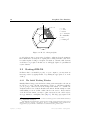
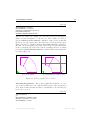
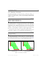
Figure 2.8: Initial geometry
What is being displayed? The working window now shows a viewport with
two large yellow circles [Fig. 2.8a]. The points of the geometry are indicated with
tiny circles. We not only see the center point, but also some at the compass
points east, north, south and west of each circle. The latter ones were automatically created as part of the circle definition. Note that iDiana draws the
circles by default with four straight chords per quarter. This is only a matter
of presentation, the exact circular shape will be applied for all manipulations
concerning the circles.
Creating a plot file. As discussed earlier, screen-dumps are not very suitable
for presentation in documents. Therefore we will now demonstrate how to create
a picture in plot format. This is not only appropriate for this manual, but also
for other technical documents about finite element analyses with Diana.
plate.fgc
UTILITY SETUP PLOTTER FORMAT POSTSCRPT COLOUR
VIEW GEOMETRY ALL VIOLET
LABEL GEOMETRY LINES ALL VIOLET
LABEL GEOMETRY POINTS
DRAWING SAVE PLOTFILE geom1.ps
yes
initial geometry
The UTILITY SETUP PLOTTER FORMAT command, with the POSTSCRPT COLOUR
option, causes iDiana to write a plot file in PostScript format [1], including
colors, whenever you give the DRAWING SAVE PLOTFILE command. In this case
we first give some VIEW and LABEL commands with the GEOMETRY option to
draw the geometry and line labels in violet because the default yellow is barely
visible on a white background, like paper.
Diana-9.3 User’s Manual – Getting Started
April 25, 2008 – First ed.
20
Graphical User Interface
Before actually writing the plot file, iDiana asks for confirmation and for a
short title which will be added below the frame. The plot file geom1.ps may be
sent directly to a PostScript device, or included in a document for instance
in this manual [Fig. 2.8b].
In the sequel of this volume, as well as in all other volumes of the Diana User’s Manual, we will present iDiana pictures in plot format
rather than as screen dumps, without showing the applied iDiana
commands that were given to get the plot files.
We have now defined the initial geometry of the model. What remains is to
cut off the quarter part, define surfaces, and create the proper outer bound
with straight lines. This will demonstrate only a few of the many iDiana
options which relieve us of the obligation to perform geometrical calculations of
coordinates.
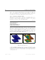
Quarter part with surfaces. We actually will define the model to be meshed
via surfaces in the north-easterly quarter of the complete circular model. As
the complete circle is divided in four equally sized lines you may create a point
on two-third along line L5, i.e., the north-easterly section of the circumscribed
circle [Fig. 2.8b]. To get a consistent mesh we also create the corresponding
point on the inner circle.
plate.fgc
GEOMETRY
GEOMETRY
GEOMETRY
GEOMETRY
GEOMETRY
GEOMETRY
SPLIT L5 0.66666667
SPLIT L1 0.66666667
LINE P2 P6
LINE BETWEEN SHORTEST L11 P9
SURFACE P1 P5 P9 P10
SURFACE P10 P9 P11 P2
With the GEOMETRY SPLIT command we split lines L5 and L1 at two-third of their
lengths. This creates two new points: P9 the vertex point on the outer edge and
P10 on the inner edge respectively. Then the GEOMETRY LINE command defines
a line between points P2 and P6, which forms the left edge along the vertical
symmetry axis. This line is straight by default, and automatically named L11.
Next you must define the horizontal top line from the vertex P9 to the vertical
symmetry line. The easiest way to do this is via the BETWEEN SHORTEST option
which creates a line along the shortest distance between two geometrical parts.
iDiana will automatically create point P10 along the vertical edge.
Now we have got all points that are necessary to define two surfaces via the
SURFACE option. The surface definition requires the points to be specified in a
circular sequence. iDiana will automatically name the surfaces S1 and S2.
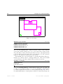
Displaying the geometry. To display the geometry we give the following
commands.
April 25, 2008 – First ed.
Diana-9.3 User’s Manual – Getting Started
2.3 Designing a Model
21
plate.fgc
VIEW GEOMETRY S1 VIOLET
VIEW GEOMETRY +S2 VIOLET
CONSTRUCT SPACE WORK-BOX 10 8.7 0
EYE FRAME WORK-BOX
DRAWING CONTENTS MONITOR OFF
First the two surfaces are displayed in violet where the prefix plus sign for
surface S2 causes its display to be superposed to that of surface S1. Next we
give the CONSTRUCT SPACE WORK-BOX command to define a viewport that just
fits the model of the quarter plate. The values 10, 8.7 and 0 specify the upper
limits of the XY Z coordinates. With the EYE FRAME WORK-BOX command we
effectuate the model display in the newly defined viewport. Unfortunately the
monitor overlaps the upper-left point of the model display. Therefore we switch
it off via the DRAWING CONTENTS MONITOR command. This clearly displays the
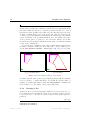
two surfaces [Fig. 2.9a].
iDIANA 9.2-08 : TNO Diana BV
11 MAR 2008 09:29:56 geom2.ps
Y
Z
iDIANA 9.2-08 : TNO Diana BV
11 MAR 2008 09:29:56 geom2.ps
Y
X
Z
(a) geometry display
X
(b) pointing with the graphics cursor
Figure 2.9: Model geometry before correction
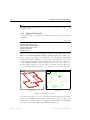
Correcting the geometry. The geometry display shows that the one outer
edge is curved. This is due to the original definition as part of the circumscribed
circle. In the actual model this edge must be a straight line, so the current model
needs some correction.
plate.fgc
UTILITY DELETE L5
yes
VIEW GEOMETRY CURRENT VIOLET
GEOMETRY SURFACE P1 P5 P9 P10
VIEW GEOMETRY +S3 RED
Diana-9.3 User’s Manual – Getting Started
April 25, 2008 – First ed.
22
Graphical User Interface
First we delete the curved line via the DELETE option. You could directly type
the line name L5 behind the command, as shown. However, particularly if the
line name is unknown, it is more convenient to indicate the line to be deleted
interactively via the graphics cursor [Fig. 2.9b]. In reality, this cursor shows up
as white crosshairs when you move the mouse cursor into the black viewport
or when you press the enter key immediately after having typed the DELETE
option. You may move the crosshairs with the mouse to the vicinity of the center
of the geometric part to be picked, i.e., the curved line. When you now click
the left mouse button iDiana will fill in the line name L5 behind the DELETE
option on the command line.
You are asked for confirmation of the deletion. If the answer is ‘yes’ then also
the surface S1 which contained the deleted line will be deleted. This is proved
via the VIEW GEOMETRY CURRENT command [Fig. 2.10a]. If you now redefine
iDIANA 9.2-08 : TNO Diana BV
11 MAR 2008 09:29:56 geom3.ps
Y
Z
iDIANA 9.2-08 : TNO Diana BV
11 MAR 2008 09:29:56 geom4.ps
Y
X
Z
(a) one remaining surface
X
(b) added surface
Figure 2.10: Correcting the plate model geometry
the surface with the same points as previously then iDiana will automatically
create a new line to complete this surface. By default the new line will be a
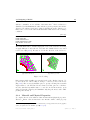
straight one, which is just what we want! The VIEW GEOMETRY command adds
the new surface S3 to the display of the geometry [Fig. 2.10b].
2.3.4
Creating a Set
As there are more geometric parts than actually are needed for the model, e.g.,
the complete inner and circumscribed circle, it is convenient for future reference
to the real model to collect the two surfaces that form the quarter plate in a
named set.
plate.fgc
CONSTRUCT SET OPEN PLATE
CONSTRUCT SET APPEND S2
CONSTRUCT SET APPEND S3
April 25, 2008 – First ed.
Diana-9.3 User’s Manual – Getting Started
2.3 Designing a Model
23
CONSTRUCT SET CLOSE
Maintenance of sets is done via the CONSTRUCT SET command. With the OPEN
option we open a new set named PLATE and with the APPEND option we put the
two surfaces in the set. Then the CLOSE option closes the set. We may now use
the set name PLATE to refer to the model of the quarter plate.
plate.fgc
VIEW GEOMETRY PLATE VIOLET
LABEL GEOMETRY POINTS
LABEL GEOMETRY LINES CURRENT VIOLET
LABEL GEOMETRY SURFACES CURRENT WHITE
The VIEW GEOMETRY command with the set name now directly displays the
model of the two surfaces [Fig. 2.11a]. The LABEL commands label the currently
iDIANA 9.2-08 : TNO Diana BV
P11
11 MAR 2008 09:29:56 geom5.ps
L12
L15
iDIANA 9.2-08 : TNO Diana BV
P9
11 MAR 2008 09:29:56 gdiv.ps
6
L14
10
10
S2
P2
L10
6
P10
S3
L16
12
L1
12
Y
Z
Y
X
PC
P1
L13
P5
(a) points, lines, surfaces
Z
X
10
(b) divisions
Figure 2.11: Geometry with labels
displayed geometric parts. Note that the WHITE option displays labels in white
on the screen, against the black background of the viewport. For the plot file
iDiana transfers the ‘color’ white to black.
2.3.5
Meshing Procedure
Now that the geometry has been defined completely we may continue with the
meshing process: specifying the Diana element type for plate elements and the
fineness of the mesh, and then performing the actual generation of the mesh.
plate.fgc
MESHING TYPES ALL QU8 CQ24P
MESHING DIVISION PROPAGATE L13 10
MESHING DIVISION PROPAGATE L1 12
MESHING DIVISION PROPAGATE L10 6
LABEL GEOMETRY OFF
Diana-9.3 User’s Manual – Getting Started
April 25, 2008 – First ed.
24
Graphical User Interface
LABEL GEOMETRY DIVISIONS
MESHING GENERATE
Due to the MESHING TYPES command, all surfaces will be meshed with the
generic QU8 elements, where ‘generic’ means that the element type only describes the shape of the element, i.e., an eight-node quadrilateral, and not the
application or stress situation. If we use the command menu and point at this
element type, the menu shows all the Diana elements that match the generic
QU8 element type for the previously specified model type. In this case we choose
the CQ24P plate bending element.
The DIVISION option controls the number of elements that iDiana will create,
i.e., the fineness of the mesh. In this case we first specify an explicit division
for a few lines. The PROPAGATE option causes the same division to be applied
for the lines’ opposite neighbors. Note that you must specify twice as much
divisions as you want to have elements along a line because the elements have
midside nodes.
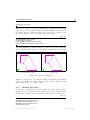
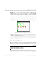
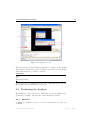
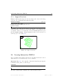
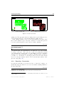
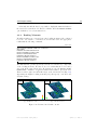
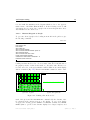
After having checked the divisions via the LABEL GEOMETRY DIVISIONS command [Fig. 2.11b], we may give the MESHING GENERATE command to let iDiana
generate the mesh.
plate.fgc
VIEW MESH
VIEW OPTIONS SHRINK
VIEW HIDDEN SHADE
After generation, the mesh will not be displayed automatically. Therefore we
give the VIEW MESH command which, by default, displays the mesh in green
wire netting style [Fig. 2.12a]. This style does not clearly show unwanted holes.
iDIANA 9.2-08 : TNO Diana BV
11 MAR 2008 09:29:56 mesh.ps
Y
Z
iDIANA 9.2-08 : TNO Diana BV
11 MAR 2008 09:29:56 mesh2.ps
Y
X
Z
(a) default display style
X
(b) shrunken elements & color fill
Figure 2.12: Generated mesh
To check for that, two viewing options are appropriate: ‘shrunken elements’
and ‘color fill’. In this case we apply these simultaneously, respectively via the
SHRINK and HIDDEN SHADE viewing options [Fig. 2.12b].
April 25, 2008 – First ed.
Diana-9.3 User’s Manual – Getting Started
2.3 Designing a Model
2.3.6
25
Boundary Constraints
Now that the mesh has been generated we have to define the boundary constraints. For this example these consist of the rigid supports and the symmetry
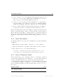
conditions. We define boundary conditions via the PROPERTY BOUNDARY CONSTRAINT command.
plate.fgc
PROPERTY
PROPERTY
PROPERTY
PROPERTY
BOUNDARY
BOUNDARY
BOUNDARY
BOUNDARY
CONSTRAINT
CONSTRAINT
CONSTRAINT
CONSTRAINT
P5 Z
P9 Z
L13 RX
L15 RY
The commands with the Z option specify a rigid support for the translation in
the global Z direction, i.e., vertically, at the two vertex points of the quarter
hexagonal plate. The commands with the RX and RY option respectively specify
a suppressed rotation around the global X and Y directions. These model the
symmetry condition along the horizontal and vertical edge. Note that it is not
necessary to specify symmetry conditions for in-plane displacements because
these are not part of the degrees of freedom for plate bending elements.
We will now check the boundary constraints by labeling the mesh. As mesh
labels cannot be displayed on a color filled mesh we first switch that off.
plate.fgc
VIEW HIDDEN OFF
LABEL MESH CONSTRNT
EYE ZOOM .647 .295 .948 .115
The LABEL MESH CONSTRNT command displays the constraints with squareheaded nails pointing in the direction of the suppressed displacement [Fig. 2.13a].
Note that in the two-dimensional view, the vertical supports appear as squares.
Also note that suppressed rotations are displayed with dual-head nails.
iDIANA 9.2-08 : TNO Diana BV
11 MAR 2008 09:29:56 constr.ps
Y
Z
iDIANA 9.2-08 : TNO Diana BV
11 MAR 2008 09:29:56 constr.ps
Y
X
Z
(a) entire model
X
(b) zoom window
Figure 2.13: Boundary constraints
Diana-9.3 User’s Manual – Getting Started
April 25, 2008 – First ed.
26
Graphical User Interface
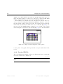
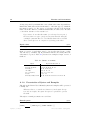
Zooming. For a closer look at the displayed boundary conditions you may
zoom in at a supported edge of the model. Therefore we give the EYE ZOOM
command which by default requires the normalized coordinates of the zoom
window within the current viewport. Instead of typing these on the command
line you may move the mouse cursor into the viewport and drag a zoom window,
from upper-left to lower-right, while pressing the left mouse button [Fig. 2.13b].
When you now release the mouse button, iDiana will substitute the coordinates of the zoom window on the command line and display the contents of the
zoom window in the entire viewport [Fig. 2.14]. Note that due to the shrunken
iDIANA 9.2-08 : TNO Diana BV
11 MAR 2008 09:29:56 constr2.ps
Y
Z
X
Figure 2.14: Boundary constraints – zoomed-in
elements view the supports seem to be ‘in the air’. In reality they are attached
to the nodes of the finite element mesh.
Instead of the ZOOM option we could have used the standard OpenGL features to zoom and translate the model interactively: press and hold down the
ctrl key and simultaneously drag the mouse cursor while respectively pressing
the middle or the right button.
2.3.7
Loading Definition
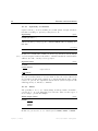
We will now apply the loads to the model via some PROPERTY LOADS commands.
There are two load cases: case 1 is the dead weight load to the entire model,
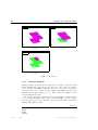
case 2 is a distributed line load along the inner circle of the plate.
plate.fgc
PROPERTY LOADS GRAVITY 1 ALL -9.8 Z
PROPERTY LOADS PRESSURE 2 L1 -20000. Z
PROPERTY LOADS PRESSURE 2 L10 -20000. Z
The dead weight load is specified with the GRAVITY load class and an acceleration
of gravity g = 9.8 in the −Z direction. The distributed line load is specified
April 25, 2008 – First ed.
Diana-9.3 User’s Manual – Getting Started
2.3 Designing a Model
27
with two commands, one for each line of the inner circle.5 The load class for a
distributed load is PRESSURE, the value and the Z option specify the size and the
direction. We will now check the loading by labeling the mesh. Therefore we
first revert to a view of the entire mesh and switch off the labels of the boundary
conditions.
plate.fgc
EYE FRAME
LABEL MESH
LABEL MESH
LABEL MESH
EYE ROTATE
OFF
LOADS 1
LOADS 2 RED
TO 45 30 30
The LABEL MESH LOADS commands display the loads on the elements. For clarity
we apply different colors for the two load cases: the default violet for case 1 and
red for case 2 [Fig. 2.15a]. Because we look in the direction of the load we see
iDIANA 9.2-08 : TNO Diana BV
11 MAR 2008 09:29:56 loads1.ps
Y
iDIANA 9.2-08 : TNO Diana BV
11 MAR 2008 09:29:56 loads2.ps
Z
Y
Z
X
X
(a) view from above
(b) bird’s-eye view
Figure 2.15: Loading
little squares which actually represent the heads of the displayed arrows. To
see the real arrows of the loading we change to a bird’s-eye view of the model
[Fig. 2.15b]. Here we use the ROTATE option to specify a viewing direction with
angles relative to the XY Z model axes. Instead of this option we could have
used the standard OpenGL feature to rotate the model interactively: press
and hold down the ctrl key and simultaneously drag the mouse cursor while
pressing the left button.
2.3.8
Material and Physical Properties
To complete the model we will now define its material and physical properties.
Therefore iDiana offers an interactive user interface with so-called property
5 Instead
of specifying a name on the command line you may pick the line via the graphics
cursor, as explained for the DELETE option [§ 2.3.3 p. 22].
Diana-9.3 User’s Manual – Getting Started
April 25, 2008 – First ed.
28
Graphical User Interface
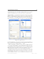
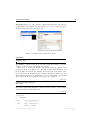
forms. To get such a form you must open the View menu (1) and choose Property
Manager (2) [Fig. 2.16]. The Property Manager dialog shows up [Fig. 2.17].
Figure 2.16: Opening the Property Manager dialog
Material properties. Now we choose the Materials tab (3) for specification of
material properties and click the Create New button (4). In the Material Name
Figure 2.17: Specification of material properties for linear elasticity
field on top we type the name of a new material: CONCRETE (5). Depending
on the type of the model there are tabs for the various aspects of the material
properties. First we choose Linear Elasticity (6). Each aspect may have various
concepts which show up in the Concepts tree where we choose Isotropic (7). We
may now fill in the parameters for isotropic linear elasticity: *Young’s modulus
and Poisson’s ratio (8). The leading star in *Young’s modulus indicates that this
parameter is obligatory, there is no default value. When we click the Confirm
April 25, 2008 – First ed.
Diana-9.3 User’s Manual – Getting Started
2.3 Designing a Model
29
button (9) the new material concept is saved and listed in the Currently Defined
field.
The second material aspect for this model is Mass, which we choose by
clicking the tab (10) [Fig. 2.18]. The concept here is Mass Density (11), for
Figure 2.18: Specification of material properties for mass
which we fill in the appropriate value (12) and click Confirm (13). We have now
specified all material parameters for the analysis of this model and click OK to
save the material CONCRETE (14).
Physical properties. The procedure to specify the physical properties, in
this case the thickness of the plate, is analogous to that for the material properties. First we click the Physical Properties tab (15) [Fig. 2.19]. Then we click
Create New (16) and fill in the name THICK for the properties that we will specify
(17). Then we activate the Geometry aspect tab (18) and choose Plate Bending →
Isotropic (19). We fill in the thickness of the plate (20) and accept the proposed
value of 1.5 for the shape factor [Vol. Element Library]. Finally we Confirm
(21) and click OK to save the specified properties (22).
Property assignment
plate.fgc
PROPERTY ATTACH PLATE CONCRETE THICK
With the PROPERTY ATTACH command we assign the properties CONCRETE and
THICK, that we have just specified via the property forms, to all the elements in
set PLATE which forms the model of the quarter hexagonal plate.
Diana-9.3 User’s Manual – Getting Started
April 25, 2008 – First ed.
30
Graphical User Interface
Figure 2.19: Specification of physical properties for geometry
2.3.9
Running a Command File
The Diana User’s Manual comprises a lot of examples of model preparation,
analysis, and postprocessing. This particular example is called plate6 and you
may find the related files in the Diana installation directory at
Examples/GetStart/plate6
You may copy the file plate.fgc to your own directory (folder), possibly modify
it, and then let iDiana read it via the UTILITY READ BATCH command.
FEMGEN PLATE
UTILITY READ BATCH plate.fgc
If the command file is syntactically correct you will see the model being created
live on the screen.
2.3.10
Saving the Current Model
The model is now complete and we can save it on an iDiana database. We
start the saving procedure [Fig. 2.20] by double clicking the SAVE command in
the Command Browser (1). In the pop-up Confirmation dialog we click Yes (2)
which brings a dialog where we may type a short description of the model (3).
Then we click OK to save the model (4). iDiana confirms a successful save
in the Messages tab. Note that the name of the model database is PLATE.G71.
April 25, 2008 – First ed.
Diana-9.3 User’s Manual – Getting Started
2.4 Performing the Analysis
31
Figure 2.20: Saving the model
The letter G in the extension indicates that this is a database for the Design
environment, 71 indicates the version. We may reopen the model in the Design
environment should we ever want to modify it.
Commands
SAVE
yes
Quarter hexagonal plate
If we add the above commands to the end of the command file plate.fgc, the
iDiana run would automatically save the model.
2.4
Performing the Analysis
The analysis procedure of the model comprises three stages: the initiation, the
specification of analysis options and the actual calculation by Diana.
2.4.1
Initiation
To initiate the analysis we can choose between an interactive procedure and
commands.
Diana-9.3 User’s Manual – Getting Started
April 25, 2008 – First ed.
32
Graphical User Interface
Interactive [Fig. 2.21]. We open the File menu (1) and choose Run → An Analysis (2). The Run an Analysis dialog pops up where we choose the appropriate
Figure 2.21: Initiating the analysis
model database by clicking its name PLATE.G71 in the list box (3). The name
appears in the File Name box and some model information is shown in the
pane below. We now click the Analyse button to start the analysis (4). An
analysis requires an input data file in Diana batch format [Ch. 3]. iDiana will
automatically write this file after our confirmation (5).
Commands
UTILITY WRITE DIANA
yes
FILE CLOSE
yes
ANALYSE PLATE
The UTILITY WRITE DIANA command will write the model in Diana batch input
format. We must confirm the writing of a new file. We close the model and
enter the Index environment via the FILE CLOSE command and type the ANALYSE
command with the name of the model PLATE.
Analysis setup. The Analysis Setup dialog appears [Fig. 2.22-left]. The three
boxes show default names which we accept for this example. The Working
Directory box indicates the place where Diana will create output files, log files
etc. The Filos File box shows the current name of the filos file, i.e., the central
April 25, 2008 – First ed.
Diana-9.3 User’s Manual – Getting Started
2.4 Performing the Analysis
33
Figure 2.22: Analysis setup and input reading
database for the analysis of the model. Here we accept Initialize New to indicate
that this is a new analysis. The Input Data File(s) box shows the name of the
input data file that was recently written. With a click on OK, Diana starts to
read the input data file.
Reading the input data. The Reading Input dialog pops up and shows a
log of the reading process [Fig. 2.22-right]. In the Messages box we see all the
input tables being read, and finally a termination log line. Any messages, errors
or warnings, would appear in the Warnings box. In this case we get no warnings
and may click OK.
Selecting the analysis type. After termination of the reading process the
Select Analysis Type dialog appears [Fig. 2.23-left] in which we must indicate
the analysis type. We accept the default Structural linear static analysis and
click OK.
2.4.2
Analysis Options
Next, the Diana Analysis dialog pops up giving the different modules that are
called during the analysis, as well as the modules that were called previously
[Fig. 2.23-right] . By right-clicking on the Structural linear static entry and choosing Edit... we enter the Structural Linear Static Settings dialog where we may
set various analysis options. [Fig. 2.24-left]. The different tabs correspond to
specific tasks in the analysis process: Model for the evaluation and setup of
the finite element model, Solve for the solution procedure, and Output for the
output selection of analysis results. For most options Diana has preset appro-
Diana-9.3 User’s Manual – Getting Started
April 25, 2008 – First ed.
34
Graphical User Interface
Figure 2.23: Analysis type selection and Diana Analysis dialog
Figure 2.24: Analysis options and on-line help
priate defaults.6 Pressing the F1 key brings a browser window with the section
of the Diana User’s manual regarding the subject in the analysis window that
6 See
April 25, 2008 – First ed.
Volume Analysis Procedures for a comprehensive description of analysis options.
Diana-9.3 User’s Manual – Getting Started
2.4 Performing the Analysis
35
currently has the keyboard control [Fig. 2.24-right]. In this case we accept the
defaults for all analysis options, except for the selection of output results.
Output selection. By default Diana will output the Cauchy stresses and the
distributed bending moments and forces. However, for a plate bending model
like the one in this example, the Cauchy stresses are less appropriate. Moreover,
we would also like to see the displacements and reaction forces. We may achieve
this via a user-specified selection [Fig. 2.25]. Therefore we first click the Output
Figure 2.25: Output selection
tab, then New Block for a new selection and User Selection in the Result box.
If we now click Modify the Results Selection dialog will appear where we may
customize the selection of analysis results to be output.
First we click DISPLA to unfold the selection options for displacements. We
see the default settings highlighted: TOTAL TRANSL GLOBAL which stands for the
total translations in the global XY Z directions. We agree with that and click
Add to move the selected result into the list of selections. We do the same for
FORCE which adds the reaction forces to the selection list (not shown).
For the stresses we check the selection of the bending moments. Therefore we
click STRESS to unfold the options for stress selection. At first we see the default
CAUCHY highlighted which stands for the Cauchy stresses. Here we don’t agree
and click DISMOM and LOCAL to select the distributed moments in the local xy
Diana-9.3 User’s Manual – Getting Started
April 25, 2008 – First ed.
36
Graphical User Interface
directions. Again by clicking Add we add the current selection to the selection
list.
We have now selected all analysis results that we want to be output and click
Close to make the selection active for the analysis. The Results Selection dialog
disappears and we are back in the Diana Structural Linear Static Settings
dialog where the selected analysis results are displayed in the Result box. We
will make no further changes to the settings of analysis options and click OK.
2.4.3
Calculation
In the menu of the Diana Analysis dialog we choose Analysis → Run (1), or
we click the I tool button. This starts the analysis. While running, Diana
logs the analysis process in the Calculating dialog [Fig. 2.26]. There are two
Figure 2.26: Analysis execution
boxes: the Messages box with log lines, and the Warnings box with warnings
and error messages. When the last log line with STOP appears, the calculation
has been terminated. If there are no error messages we may click OK (2) and
the Calculating dialog will disappear.
2.5
Postprocessing
The analysis run has created an iDiana database called PLATE.V71. The letter
V in the extension indicates that this is a database for the Results environment
where we can assess the analysis results. The number 71 indicates the version.
We may open this database, and enter the Results environment, in two ways:
interactively via the File menu or with a command.
April 25, 2008 – First ed.
Diana-9.3 User’s Manual – Getting Started
2.5 Postprocessing
37
Interactive [Fig. 2.27]. Choosing File → Open in the Menu Bar of the iDiana
working window (1) brings the Open dialog where we can choose the appropriate
database PLATE.V71 (2) and click Open (3).
Figure 2.27: Entering the Results environment
Command
FEMVIEW PLATE
The FEMVIEW command with the model name PLATE as parameter opens the
database of this model for the Results environment.
Either way of entering the Results environment brings the iDiana working window as shown in Figure 2.28. The FV> prompt indicates that we are
in the Results environment (1). Initially the Monitor shows the name of the
model (2) and in the Graphics Window iDiana displays an outline view (3).
The Command Browser now displays the top-level commands for the Results
environment (4). We start with the following general commands.
plate.fvc
UTILITY TABULATE LOADCASES
VIEW MESH
The UTILITY TABULATE LOADCASES command tabulates all load cases and their
available results in the Tabulation tab:
lcase.tb
;
; Model: PLATE
;
;
LOADCASE DATA
;
; Name
Details and results stored
; ----------------------------;
; MODEL
STATIC "Model Properties"
;
Element : THICKNES*
Diana-9.3 User’s Manual – Getting Started
April 25, 2008 – First ed.
38
Graphical User Interface
Figure 2.28: The Results working window
;
;
;
;
;
;
;
;
;
;
LC1
STATIC "Load case 1"
Nodal
: DTX....G FBX....G
Element : EL.MXX.L
LC2
STATIC "Load case 2"
Nodal
: DTX....G FBX....G
Element : EL.MXX.L
* Indicates loads data
There are two load cases: LC1 the dead weight and LC2 the line load along the
inner circular edge. The available analysis results are the total displacements
DT and support reactions FB in the nodes, and bending moments EL.M for the
elements. To prepare the results presentation we first display the undeformed
mesh in the default green wire netting style by giving the VIEW MESH command.
2.5.1
Displacements
iDiana can present the displacements of a finite element model in various styles.
We will demonstrate the most appropriate ones for this example: contour plot
and deformed mesh.
Contour plot
April 25, 2008 – First ed.
plate.fvc
Diana-9.3 User’s Manual – Getting Started
2.5 Postprocessing
39
RESULTS LOADCASE LC1
RESULTS NODAL DTX....G DTZ
PRESENT CONTOUR LEVELS
First we select the analysis results to be displayed with two RESULTS commands:
the LOADCASE option selects load case LC1. The NODAL option with the DT
attribute selects the displacements in the nodes. Furthermore, with DTZ, we
select the vertical (Z) component of the displacements. To present the selected
results we give the PRESENT command. The CONTOUR LEVELS options asks
iDiana to display the contours for the selected result in default style: color
filled with ten levels [Fig. 2.29a].
iDIANA 9.2-08 : TNO Diana BV
11 MAR 2008 09:29:59 lc1dc.ps
Model: PLATE
LC1: Load case 1
Nodal DTX....G DTZ
Max = 0
Min = -.116
-.106E-1
-.212E-1
-.318E-1
-.423E-1
-.529E-1
-.635E-1
-.741E-1
-.847E-1
-.953E-1
-.106
Y
Z
iDIANA 9.2-08 : TNO Diana BV
11 MAR 2008 09:29:59 lc2ds.ps
Model: PLATE
LC2: Load case 2
Nodal DTX....G DTZ
Max = 0
Min = -.741E-1
Factor = 9.1
X
(a) load case 1 uZ contours
Z
Y
X
(b) load case 2 deformation
Figure 2.29: Displacements
Results monitor. The monitor in the upper-left corner of the viewport gives
some information about the displayed results, notably the extreme value which
is −0.116 in this case and indicates the maximum vertical displacement. iDiana
also displays a legend in the lower-right corner of the viewport which gives the
bounding values for each color. The colors are modulated from red for the
maximum to blue for the minimum. But take care! As the displacements are all
negative, i.e., downward in the −Z direction, the blue areas indicate the largest
displacements.
Deformed mesh
plate.fvc
RESULTS LOADCASE LC2
EYE ROTATE TO 45 30 30
EYE FRAME
PRESENT SHAPE
To demonstrate the display of a deformed mesh we first select the results for
load case LC2. With no further RESULTS command the vertical displacements
will remain selected. A deformation in the viewing direction would be invisible.
Diana-9.3 User’s Manual – Getting Started
April 25, 2008 – First ed.
40
Graphical User Interface
Therefore we change to the familiar bird’s-eye view via the EYE commands. Next
the PRESENT SHAPE command displays the deformed mesh in red [Fig. 2.29b].
The results monitor now also shows the multiplication factor that iDiana has
applied to achieve an easily perceptible deformation, in this case 9.1×.
2.5.2
Bending Moments
We will now make some plots for the bending moments of the currently selected
load case LC2.
Vector plot
plate.fvc
RESULTS ELEMENT EL.MXX.L MXX
RESULTS CALCULATE P-STRESS ALL
PRESENT VECTORS
First we select the bending moments in the elements via the ELEMENT option
and the EL.M... attribute. Because we will let iDiana calculate the principal
moments m1,2 the component is arbitrary, here we choose MXX for mxx . Then
we ask iDiana to calculate the principal moments via the RESULT CALCULATE
P-STRESS command. The PRESENT VECTORS command displays the principal
moments m1,2 in vector style [Fig. 2.30a].
iDIANA 9.2-08 : TNO Diana BV
11 MAR 2008 09:29:59 lc2mp.ps
Model: PLATE
LC2: Load case 2
Element PRINC STRESS ALL
Calculated from: EL.MXX.L
Max = .224E5
Min = -.155E6
Factor = .436E-5
iDIANA 9.2-08 : TNO Diana BV
11 MAR 2008 09:29:59 lc2mv.ps
Model: PLATE
LC2: Load case 2
Element VONMISES EL.MXX.L
Calculated from: EL.MXX.L
Max = .155E6
Min = .263E5
Z
.143E6
.131E6
.12E6
.108E6
.963E5
.847E5
.73E5
.613E5
.496E5
.38E5
Z
Y
Y
-.367E5
-.958E5
X
(a) vectors for principal moments
X
(b) contours for equivalent moments
Figure 2.30: Bending moments
Contour plot
plate.fvc
RESULTS CALCULATE VONMISES
PRESENT CONTOUR LEVELS
Contour plots are especially instructive for scalar or single value results. To
display a contour plot of the bending moments we need the equivalent moments.
Therefore we ask iDiana to calculate these from the currently selected result
item via the VONMISES option. Then the PRESENT CONTOUR LEVELS command
displays the contours [Fig. 2.30b].
April 25, 2008 – First ed.
Diana-9.3 User’s Manual – Getting Started
2.6 Leaving Interactive DIANA
2.5.3
41
Support Reactions
Finally we will assess the support reactions, acting at the corners of the hexagonal outer edge by displaying their numerical values.
Numerical display
plate.fvc
RESULTS NODAL FBX....G FBZ
PRESENT OPTIONS NUMERIC MODULATE OFF
PRESENT NUMERIC
The NODAL option with the FB attribute and the FBZ component selects the
vertical reaction forces in the nodes. For value display color modulation is not
very suitable. Therefore we switch that off via the NUMERIC MODULATE option
then the PRESENT NUMERIC command displays the values of the reaction forces
at their proper location [Fig. 2.31].
iDIANA 9.2-08 : TNO Diana BV
11 MAR 2008 09:29:59 lc2re.ps
Model: PLATE
LC2: Load case 2
Nodal FBX....G FBZ
Max = -.419E5
Min = -.838E5
-.838E5
Z
Y
-.419E5
X
Figure 2.31: Support reactions
2.6
Leaving Interactive DIANA
We now terminate this example and may leave the iDiana interactive session.
Again, this can be done interactively or via a command.
Interactive [Fig. 2.32]. Choosing File → Exit in the Menu Bar (1) brings the
Confirmation dialog where we click Yes (2).
Command
STOP
yes
The STOP command with confirmation also exits the iDiana session.
Diana-9.3 User’s Manual – Getting Started
April 25, 2008 – First ed.
42
Graphical User Interface
Figure 2.32: Leaving the Diana Graphical User Interface
April 25, 2008 – First ed.
Diana-9.3 User’s Manual – Getting Started
Chapter 3
Batch User Interface
Most users, even the more experienced ones, will use the iDiana Graphical
User Interface as introduced in Chapter 2. However, as a novice user you are
encouraged to read this chapter as well because it not only introduces the Diana
batch interface, but also the setup of the Diana User’s Manual and the general
aspects of performing a Finite Element Analysis with Diana. Moreover, most
volumes of the User’s Manual formally describe the input, analysis, and output
of a finite element model in terms of the batch interface, which is another good
reason to study this chapter.
User
file .dat
input
file .dcf
commands
filos
file
file .out
standard
output
file .tb
tabular
output
postprocessing
Diana
Figure 3.1: Batch interface
What is the batch interface? In the Diana batch interface [Fig. 3.1], you
must supply Diana with two files: an input data file which describes the finite
element model [§ 3.1], and a command file which tells Diana how to analyze
it [§ 3.2.1]. From these two files Diana can setup and solve the system of
equations and produce analysis results on a tabular output file [§ 3.2.3], or on a
postprocessing file for interactive graphics postprocessing with iDiana [§ 3.2.4].
Diana-9.3 User’s Manual – Getting Started
April 25, 2008 – First ed.
44
Batch User Interface
The next sections describe the various parts of the batch interface in more
detail. You will also meet two more files: the filos file which is the internal
database where Diana stores all intermediate data, and the standard output file
which informs you about the performance of the analysis job [§ 3.2.2].
3.1
Input Data File
The input data file is a text-format file which you may produce and modify
with any convenient text editor, for instance vi or xedit on a unix system, or
notepad on a PC under MS-Windows. The input data file describes the entire
finite element model, including the node coordinates, elements and connectivity,
boundary conditions, loading etc. See § A.2 on page 85 for a formal description
of the input data format in the batch interface.
Example. To make the descriptions of the batch interface more realistic we
will use a simple example of a two-dimensional crossed frame as shown in Figure
3.2.1 For a first impression, we show the complete input data file for this example
below.
F
3
q
4 7
1
2
Y
5
X
Z
Figure 3.2: Two-dimensional crossed frame
Input data
file .dat
2-D Crossed Frame
Example for Volume "Getting Started"
’COORDI’ DI=2
1
1.0 2.0
2
5.0 2.0
3
1.0 3.0
4
0.0 2.0
5
1.0 0.0
1 The example is called cframe and you may find the related files in the Diana installation directory at Examples/GetStart/cframe. For more examples see also Volume Analysis
Examples.
April 25, 2008 – First ed.
Diana-9.3 User’s Manual – Getting Started
3.1 Input Data File
45
7
0.5 2.0
’ELEMEN’
CONNEC
1
L6BEN 4 7
2
L6BEN 7 1
3
L6BEN 1 2
4
L6BEN 5 1
5
L6BEN 1 3
MATERI
/ 1-5 /
1
GEOMET
3
1
/ 1 2 5 / 2
4
3
’MATERI’
1
YOUNG
2.0E11
POISON 0.0
’GEOMET’
1
INERTI 21.33333333E-8
CROSSE 16.0E+2
2
INERTI
0.083333333E-8
CROSSE
1.0E+2
3
INERTI
1.333333333E-8
CROSSE
4.0E+2
’SUPPOR’
/ 2 4 5 / TR 1 TR 2 RO 3
3
TR 1 TR 2
’LOADS’
CASE 1
NODAL
7
FORCE 2 -1.0E5
ELEMEN
3
LINE
FORCE -1.0E3
DIRECT 2
’END’
The actual input data file is shown between two rules. The top rule may be
headed with a short description at the left. The indication file .dat at the
right means that the specimen shows an input data file, or a part thereof, which
must have the extension .dat. You may choose the actual file name as you
like; in this case we have chosen file name frame.dat. The tick marks on the
rules indicate input fields, as we will explain later.
Basically, the input data file is subdivided in tables, where each table comprises a particular part of the input for the finite element model, for instance the
node coordinates or the elements. Each table is denoted by a heading name of six
significant letters enclosed in single quotes, for instance the first table ’COORDI’.
For your own convenience you may use more letters, like ’COORDINATES’.
Diana-9.3 User’s Manual – Getting Started
April 25, 2008 – First ed.
46
Batch User Interface
Note that some lines of text may precede the first table. This title may serve
as an annotation of the data file. Also note that the last table of the input data
file is terminated by an ’END’ line. This does not necessarily terminate the data
file itself because you may put more lines of text behind it. However, Diana
will ignore all lines following the ’END’ line when reading the input data. It is
not only a place to put comments, annotation etc., but also a convenient place
to put data lines which are temporarily out of order. We will now describe the
various input tables of this example in more detail.
3.1.1
Node Coordinates
Let us first explain how you must specify node coordinates. You should look
in Volume Analysis Procedures of the User’s Manual in which the section on
‘Node Coordinates’ in Chapter 1 tells you how to input node coordinates. For
the two-dimensional crossed frame it could be like this:
Two-dimensional coordinates
frame.dat
’COORDI’ DI=2
1
1.0 2.0
2
5.0 2.0
3
1.0 3.0
4
0.0 2.0
5
1.0 0.0
7
0.5 2.0
On the first line you see the table heading ’COORDI’. Behind the table name
you see DI=2, this is a parameter indicated by a word of at most six letters, an
equal sign, and a value. This particular parameter indicates the dimensionality
of the model, i.e., coordinates are specified in a two-dimensional XY system.
The table name and the parameter together form the table heading. The lines
following the heading contain three values each: respectively a node number, the
X coordinate, and the Y coordinate. Note that node numbers may be omitted,
they may even be specified in arbitrary order.
Syntax description. The User’s Manual formally describes the syntax of
input table ’COORDI’ between two fat rules like this:
syntax
’COORDI’ [ DI=dimens n ]
1
5 6
node n
80
x r y r [z r ]
Now what does this mean? The word syntax indicates that this is a formal
syntax description [§ A.1.4 p. 79].2 The typewriter style of the letters in between
2 For
April 25, 2008 – First ed.
styles of references in the User’s Manual see § A.1.2 on page 78.
Diana-9.3 User’s Manual – Getting Started
3.1 Input Data File
47
the rules indicate that it concerns the Diana batch interface [§ A.1.1 p. 77]. In
formal syntax descriptions the names, parameters etc. are typeset in capitals.
However, in reality you may also type in lower case.
The notation dimens n in the description of parameter DI means that you
must fill in a number, i.e., an unsigned whole value [§ A.1.3 p. 78]. The square
brackets around the parameter indicate optionality: you may omit the parameter. However, in that case Diana assumes that you specify the coordinates in
a three-dimensional system as indicated in the margin [§ A.1.6.1 p. 82].
The two thin rules below the table heading, with tiny numbers between their
ends, represent the fields in the input data file [§ A.2.3 p. 86]. The table with
node coordinates has two fields: the first from column 1 to 5, and the second
from column 6 to 80. What you must specify in the fields is indicated below
the bars: a node number somewhere in the first field and the coordinates x , y ,
and z in the second field. The subscript r means that you must type a real, i.e,
a floating point value including a decimal point. Note that z is optional, only
necessary if you apply a three-dimensional coordinate system.
3.1.2
[DI=3]
Elements
In the batch interface, you must specify the elements in the finite element model
in table ’ELEMEN’ in the input data file. In the section on ‘Elements’ of Chapter
1 of Volume Analysis Procedures you may find the syntax description and some
examples. For the two-dimensional crossed frame this could be like this.
frame.dat
’ELEMEN’
CONNEC
1
L6BEN
2
L6BEN
3
L6BEN
4
L6BEN
5
L6BEN
MATERI
/ 1-5 /
1
GEOMET
3
1
/ 1 2 5 / 2
4
3
4
7
1
5
1
7
1
2
1
3
The table ’ELEMEN’ comprises three so-called subtables, the first one being
CONNEC with element types and connectivity. In this example we model the
crossed frame with five beam elements of type L6BEN. Volume Element Library
explains what type of elements these are, including a description of their mechanical properties and some background theory. Each L6BEN beam element is
connected to two nodes, as specified behind their type names.
The second subtable MATERI assigns a set of material properties to each
element. In this example all five elements, specified by a range 1-5 in between
Diana-9.3 User’s Manual – Getting Started
April 25, 2008 – First ed.
48
Batch User Interface
slashes [§ A.1.5 p. 79], have the properties of material one. The last subtable
is GEOMET which assigns a set of geometrical properties to each element. Note
that elements 1, 2, and 5 have identical geometrical properties, elements 3 and
4 each have other properties. In the next section you will see how to specify the
material and geometrical properties.
3.1.3
Material and Geometry Properties
In the previous section we showed how a specific set of material properties was
assigned to elements via subtable MATERI. Now you must specify the actual
properties of the material in table ’MATERI’. Diana supports a lot of material
models, depending on the type of analysis. Volume Material Library formally
describes their input data and background theory. For the crossed frame in this
example we will perform a linear static analysis which requires the properties
for linear elasticity:
frame.dat
’MATERI’
1
YOUNG
POISON
2.0E11
0.0
Note that ’MATERI’ is a three-field table [§ A.2.3 p. 87]: a material number in
the first field, property names of six characters in the second field, and the actual
values for each property in the third field. In this case YOUNG specifies a Young’s
modulus of elasticity E = 2 × 10¹¹ . Note the scientific notation of the floating
point vale [§ A.1.3 p. 78]. The property POISON [sic] specifies a Poisson’s ratio
ν = 0.
Like for the material properties, you must specify the geometry properties
of the elements in a separate table called ’GEOMET’. The required properties
depend on the element type and therefore are formally described in Volume
Element Library. Basically, beam elements in a two-dimensional model require
a moment of inertia Iz and an area of cross-section A:
frame.dat
’GEOMET’
1
INERTI
CROSSE
2
INERTI
CROSSE
3
INERTI
CROSSE
21.33333333E-8
16.0E+2
0.083333333E-8
1.0E+2
1.333333333E-8
4.0E+2
Note that a number in the first field indicates the start of a new set of geometry
properties.
April 25, 2008 – First ed.
Diana-9.3 User’s Manual – Getting Started
3.1 Input Data File
3.1.4
49
Boundary Conditions
The boundary conditions for the finite element model basically define the restrictions on the degrees of freedom in the nodes. Most notably these are the
supports which define a fixed value, usually zero, to a displacement or rotation.
Other boundary conditions are the linear constraints or tyings which define
linear relations between certain degrees of freedom. In the cross-frame example there are only rigid supports which you must define in table ’SUPPOR’ of
the input data file. The formal description of this table is given in Chapter 2
of Volume Analysis Procedures. For the cross-frame example the input of the
supports is as follows.
frame.dat
’SUPPOR’
/ 2 4 5 / TR 1
3
TR 1
TR 2
TR 2
RO 3
A supported degree of freedom is defined by a node number, a type (translation
or rotation) and a direction. In the first line of the example above you see a
set of nodes, 2, 4 and 5, which all have the same support: translations in the
X and Y direction, and rotation around the Z direction. Note that the set of
nodes is delimited by slashes, and that the translations are indicated by TR and
the rotations by RO. The directions are indicated by a number: 1, 2, or 3. These
numbers refer to the default set of built-in directions: X, Y , and Z respectively.
You could also specify supports in arbitrary directions with numbers greater
than 4. However, in that case you must define the actual direction in a table
’DIRECT’, like shown below.
file .dat
’SUPPOR’
/ 2 4 5 /
3
’DIRECT’
4
1.
5
-1.
TR 4
TR 1
TR 5
TR 2
RO 3
1. 0.
1. 0.
The directions are specified by their vector components in the model XY Z
coordinate system. Direction 4 points under 45° in the +X, +Y quadrant and
direction 5 also under 45° but in the −X, +Y quadrant.
3.1.5
Loading
The loading on the finite element model is defined in table ’LOADS’. You may
specify various types of loads: nodal loads, element loads or deformations. The
loads may be subdivided in load cases. For general syntax of load input see § 2.3
in Volume Analysis Procedures. For the cross-frame example there is one load
case which contains a nodal load and an element load like shown below.
Diana-9.3 User’s Manual – Getting Started
April 25, 2008 – First ed.
50
Batch User Interface
frame.dat
’LOADS’
CASE 1
NODAL
7
FORCE 2 -1.0E5
ELEMEN
3
LINE
FORCE -1.0E3
DIRECT 2
The CASE 1 line starts a new load case, with number one. Subtables NODAL and
ELEMEN respectively denote the following input data to be a nodal or an element
load. The nodal load is specified by a node number 7, a type FORCE, a direction
2 which by default refers to the model Y direction, and a magnitude of −1×10⁵ ,
where the minus sign causes the force to act in the negative Y direction.
For the element load we have specified a distributed LINE load in element 3,
acting along the element axis in the negative Y direction with a magnitude of
1000 per unit of length. As the input of element load depends on the type of the
element, the formal syntax description of element load is described in Volume
Element Library for each element family.
If we would have defined multiple load cases, we could have combined these
into one or more load sets for which Diana will calculate the analysis results.
In this example we don’t specify load sets and, by default, Diana assumes a
one-to-one relation between load cases and load sets. So we have a single load
set number 1, which is equivalent to the specified load case 1.
3.2
Performing the Analysis
Now that the input data file has been completed, we may perform the analysis.
For the cross-frame we will do a regular linear static analysis as described in
Chapter 4 of Volume Analysis Procedures.
3.2.1
Analysis Commands
To perform the analysis you must create a command file with extension .dcf.
A simple command file for linear static analysis is shown below.
linsta.dcf
*FILOS
INITIA
*INPUT
*LINSTA
BEGIN OUTPUT TABULA
DISPLA
STRESS LOCAL
April 25, 2008 – First ed.
Diana-9.3 User’s Manual – Getting Started
3.2 Performing the Analysis
51
END OUTPUT
*END
The commands with a star are so-called module commands, these invoke a
particular module of the Diana package. The *FILOS command invokes Module
filos to maintain the filos file. In this case the subsequent INITIA command
initializes a filos file for a new analysis. See § 3.2 in Volume Analysis Procedures
for more information on filos file maintenance. The *INPUT command starts
Module input which by default reads the complete input data file. In § 3.3 of
Volume Analysis Procedures all options of Module input are described.
The actual linear static analysis is performed by Module linsta, invoked
via the *LINSTA command. By default, the analysis includes all the necessary
steps to set up and solve the system of equations for the finite element model.
This solution basically produces the displacements of the nodes. However, by
default Diana does not give any tabular output of analysis results.
With commands in an OUTPUT block, delimited by the BEGIN and END keywords, you may indicate which output results you would like to see. In this case
the TABULA option asks for output in tabular format. Furthermore, the DISPLA
command asks for the displacements of the nodes and the STRESS command for
the stresses in the elements. Due to the LOCAL option Diana will output the
stresses oriented in local element axes.
Finally, the *END command terminates the analysis commands. For full
description of command options for Module linsta see Chapter 4 in Volume
Analysis Procedures.
3.2.2
Running a Batch Analysis Job
To run a batch analysis job you must start Diana and specify the names of the
appropriate files. You must specify at least the names of the input data and
command file that we just described and the name of the filos file, i.e., the
central database for the analysis. The most simple way is to specify only a base
name, like this
diana frame
Now the program diana is started and assumes an input data file frame.dat, a
command file frame.dcf, and a filos file frame.ff, all in the current directory.
All output will go to a file with base name frame. For this example we have
batch commands on a file linsta.dcf and may start the analysis job like this:
diana frame linsta.dcf
When the run is terminated, the standard output file frame.out shows a log
of the run, including any error messages or warnings that Diana might have
generated. The actual tabular output of the analysis results is on a file with
extension .tb, in this case frame.tb.
Diana-9.3 User’s Manual – Getting Started
April 25, 2008 – First ed.
52
Batch User Interface
We have explained the most simple way of running analysis jobs. For further
options, like setting file names in environment variables, monitoring a job, types
of messages etc., see Appendix B.
3.2.3
Tabular Output of Results
For the analysis job that we ran in the previous section, the tabular output file
is like shown below.
frame.tb
Analysis type
Load case nr.
Result
Axes
Nodnr
1
2
3
4
5
7
LINSTA
1
DISPLA TOTAL
GLOBAL
DtX
DtY
-7.949E-12 -9.234E-10
0.000E+00 0.000E+00
0.000E+00 0.000E+00
0.000E+00 0.000E+00
0.000E+00 0.000E+00
-3.975E-12 -3.153E+00
Analysis type
Load case nr.
Result
Axes
Location of results
Elmnr Nodnr
1
4
7
2
7
1
3
1
2
4
5
1
5
1
3
DtZ
0.000E+00
0.000E+00
0.000E+00
0.000E+00
0.000E+00
0.000E+00
LINSTA
1
STRESS TOTAL
LOCAL
NODES
Sxx
-1.590E+00
-1.590E+00
-1.590E+00
-1.590E+00
3.975E-01
3.975E-01
-9.234E+01
-9.234E+01
1.847E+02
1.847E+02
TRANSL
CAUCHY
Sxy
-5.023E+02
-5.023E+02
4.977E+02
4.977E+02
-3.521E+00
-1.021E+00
-2.271E+00
-2.271E+00
-1.136E+00
-1.136E+00
Basically there are two tables of output: the displacements for the nodes and the
stresses for the elements. Each table is preceded by some general information
like the analysis type, the load set number, the type of result etc. Note that
each column of the tables is headed by a so-called label which associates the
printed values with a particular analysis result. For instance DtY stands for the
translational displacement in the global Y direction uY , and Sxx for the Cauchy
stress σxx . In § 4.2 of Volume Analysis Procedures you may find a description
of analysis results that Diana can output for a linear static analysis, including
tables which associate an output label to a particular result item.
3.2.4
Output for Interactive Graphics Postprocessing
To get output for interactive graphics postprocessing with iDiana, for instance
to create pictures, you may add the FEMVIE output device option to the OUTPUT
April 25, 2008 – First ed.
Diana-9.3 User’s Manual – Getting Started
3.2 Performing the Analysis
53
command block, like shown below.3
file .dcf
BEGIN OUTPUT FEMVIE
DISPLA
STRESS
STRAIN
END OUTPUT
With these commands the results are written to an iDiana database with model
name FRAME which may be processed interactively in the iDiana Results working environment as described in § 2.5 on page 36.
3 FEMVIE
is also the default output device.
Diana-9.3 User’s Manual – Getting Started
April 25, 2008 – First ed.
54
April 25, 2008 – First ed.
Batch User Interface
Diana-9.3 User’s Manual – Getting Started
Chapter 4
Analysis of a Concrete
Floor
This chapter is a further introduction to Diana’s Graphical User Interface,
also known as iDiana. Here we will not emphasize the more basic features as
introduced in Chapter 2 but concentrate ourselves on the more advanced ones.
We will discuss the application of beam elements, including special aspects of
postprocessing like making a graph of a moment diagram. We will also introduce
a more automatic meshing algorithm and apply a special iDiana option to check
the quality of the mesh. Furthermore, some general features regarding pre- and
postprocessing with iDiana will be shown that were not introduced earlier, for
instance the application of load case combinations.
4.1
Finite Element Model
We will demonstrate the linear elastic analysis of a concrete floor of a house as
shown in Figure 4.1 on the next page. The finite element model will consist
of CQ24P plate bending elements for the floor and CL18B beam elements for
the girder. We will concentrate on the methods for creating the model and
postprocessing the results, rather than examining the results of the analysis.
4.2
Preprocessing
For this example we use the name FLOOR and enter the Design environment via
the following commands.1
1 The example is called cfloor and you may find the related files in the Diana installation
directory at Examples/GetStart/cfloor.
Diana-9.3 User’s Manual – Getting Started
April 25, 2008 – First ed.
56
Analysis of a Concrete Floor
9.00
3.50
Y
X
4.50
6.50
wall
girder
ROOM
GARAGE
6.00
4.00
7.00
5.50
Figure 4.1: Model
FEMGEN FLOOR
...
Analysis and Units
In the Analysis and Units dialog we indicate that this model is for three-dimensional structural analysis. Furthermore we specify that the model will be
defined in SI-units [m, kg, s, K]. In this example, we will perform the various
tasks to build the finite element model in the following sequence.
1. Define the geometry of the model [§ 4.2.1].
2. Generate the mesh and check its quality [§ 4.2.2].
3. Define and check the boundary constraints [§ 4.2.3].
4. Define the material and physical properties [§ 4.2.5].
5. Define and check the loading [§ 4.2.6].
In practice, task 2 can also be performed after 3, 4, and 5. In that case you
should perform the checks after the meshing process.
4.2.1
Geometry Definition
Generally, in a three-dimensional model, the geometry is defined by points,
lines between points, surfaces between lines, and bodies between surfaces. In
April 25, 2008 – First ed.
Diana-9.3 User’s Manual – Getting Started
4.2 Preprocessing
57
this rather simple example we will first define points [§ 4.2.1.1], and then surfaces
between these points [§ 4.2.1.2]. iDiana will generate the lines automatically
with the surfaces
4.2.1.1
Points
As a first action in the Design environment we will create some points on the
contours of the various areas of the model, indicated with ◦ in Figure 4.1. In
this case it is suitable to give a number of GEOMETRY POINT commands with the
coordinates in the XY axis system of each individual point.
floor.fgc
GEOMETRY
GEOMETRY
GEOMETRY
GEOMETRY
GEOMETRY
GEOMETRY
GEOMETRY
GEOMETRY
GEOMETRY
GEOMETRY
GEOMETRY
GEOMETRY
GEOMETRY
GEOMETRY
GEOMETRY
GEOMETRY
GEOMETRY
GEOMETRY
GEOMETRY
GEOMETRY
GEOMETRY
GEOMETRY
GEOMETRY
GEOMETRY
GEOMETRY
POINT
POINT
POINT
POINT
POINT
POINT
POINT
POINT
POINT
POINT
POINT
POINT
POINT
POINT
POINT
POINT
POINT
POINT
POINT
POINT
POINT
POINT
POINT
POINT
POINT
00
3.5 0
0 -6.5
7 -6.5
5.5 -.5
3.5 -.5
7 -10.5
5.5 0
3.5 -2.5
0 -2.5
4.5 -.5
4.5 -2.5
5.5 -2.5
90
9 -2.5
9 -4.5
12.5 -4.5
12.5 -10.5
3.5 -1
4.5 -1
11 -8.5
12 -8.5
12 -10
11 -10
9 -6.5
Note that it is not necessary to give numbers or names to the specified points,
iDiana will automatically enumerate the created points: P1, P2, · · · etc.
floor.fgc
EYE FRAME
LABEL GEOMETRY POINTS
The EYE FRAME command automatically scales the display such that the geometry will fit in the viewport. The LABEL GEOMETRY command labels the displayed
points with their names [Fig. 4.2].
4.2.1.2
Surfaces
Now we will define all surfaces with the GEOMETRY SURFACE command.
we use the 4POINTS option to define quadrilateral surfaces.
Diana-9.3 User’s Manual – Getting Started
First
April 25, 2008 – First ed.
58
Analysis of a Concrete Floor
iDIANA 9.2-08 : TNO Diana BV
11 MAR 2008 09:30:08 points.ps
Model: FLOOR
Analysis: DIANA
Model Type: Structural 3D
P1
P2
P10
P8
P6
P11
P19
P20
P9
P12
P14
P5
P13
P15
P16
P3
P4
P17
P25
P21
P22
P24
P23
Y
Z
X
P7
P18
Figure 4.2: Generated points
floor.fgc
GEOMETRY
GEOMETRY
GEOMETRY
GEOMETRY
SURFACE
SURFACE
SURFACE
SURFACE
4POINTS
4POINTS
4POINTS
4POINTS
P20 P11 P6 P19
P13 P5 P11 +P20 P12
P15 P14 P8 +P5 P13
P9 +P19 +P6 P2 P1 P10
iDiana will automatically enumerate the four created surfaces: S1 to S4. Note
the use of the plus sign to indicate midside points of so-called ‘combined lines’.
Next we will define the outer lines of the plate part surrounding the first staircase
and simultaneously put them in a set.
floor.fgc
CONSTRUCT SET OPEN GARAGE
GEOMETRY LINE STRAIGHT P7 P18
GEOMETRY LINE STRAIGHT P18 P17
GEOMETRY LINE STRAIGHT P17 P16
GEOMETRY LINE STRAIGHT P16 P25
GEOMETRY LINE STRAIGHT P25 P4
GEOMETRY LINE STRAIGHT P4 P7
CONSTRUCT SET CLOSE
The CONSTRUCT SET OPEN command opens a set GARAGE. Then the GEOMETRY
LINE STRAIGHT commands define the lines and put them in the set. The CONSTRUCT SET CLOSE command terminates the specification of lines in set GARAGE.
We will now open a set HOLE for the outer lines of the staircase hole in the floor
of the garage, and create the lines.
April 25, 2008 – First ed.
Diana-9.3 User’s Manual – Getting Started
4.2 Preprocessing
59
floor.fgc
CONSTRUCT SET OPEN HOLE
GEOMETRY LINE STRAIGHT P24 P23
GEOMETRY LINE STRAIGHT P22 P21
GEOMETRY LINE STRAIGHT P21 P24
GEOMETRY LINE STRAIGHT P23 P22
CONSTRUCT SET CLOSE
GEOMETRY SURFACE REGION S5 GARAGE HOLE
The command GEOMETRY SURFACE REGION creates a surface S5 for the plate
around the staircase hole in the garage using the sets GARAGE and HOLE. Next
we create a set named ROOM, containing the outer lines of the last part of the
floor.
floor.fgc
CONSTRUCT SET OPEN ROOM
GEOMETRY LINE STRAIGHT P10 P3
GEOMETRY LINE STRAIGHT P3 P4
GEOMETRY LINE STRAIGHT P16 P15
GEOMETRY LINE STRAIGHT P12 P9
LABEL GEOMETRY LINES
CONSTRUCT SET APPEND LINES L25 L24 L10 L5 L15
CONSTRUCT SET CLOSE
GEOMETRY SURFACE REGION ROOM
We need the LABEL GEOMETRY command to display the labels for the lines that
we must specify in the subsequent CONSTRUCT SET command. The GEOMETRY
SURFACE REGION command creates a surface S6 for the last part of the floor using
the set ROOM.
4.2.1.3
Geometry Display
We give the following commands to display and label the geometry of the model.
floor.fgc
VIEW GEOMETRY ALL VIOLET
LABEL GEOMETRY LINES ALL VIOLET
LABEL GEOMETRY SURFACES ALL BLUE
The VIEW GEOMETRY command displays the lines and points of the geometry in
violet [Fig. 4.3]. Then the LABEL GEOMETRY commands will add labels for lines
and surfaces.
4.2.2
Meshing
Now that the geometry has been defined completely we may continue with the
meshing process. Before actually generating the mesh we specify the Diana
element type for plate elements and for the girder. Furthermore, we set the
basic size of the elements and alter some of the divisions for a regular mesh.
Finally we generate the mesh.
Diana-9.3 User’s Manual – Getting Started
April 25, 2008 – First ed.
60
Analysis of a Concrete Floor
iDIANA 9.2-08 : TNO Diana BV
11 MAR 2008 09:30:08 geom.ps
Model: FLOOR
Analysis: DIANA
Model Type: Structural 3D
L18
L19
S4
L34 L5
L15
L31
L12
L13
L17
L7
L2
L3 S1
L14
L1
L4
L9 S2
L8
L20
L6
L16
S3
L11
L10
L33
S6
L23
L24
L32
L25
S5
L26
L28
L22
L29
Y
L30
L27
Z
X
L21
Figure 4.3: Geometry
Element types and size
MESHING
MESHING
MESHING
MESHING
MESHING
floor.fgc
TYPES ALL QU8 CQ24P
TYPES L15 BE3 CL18B
DIVISION ELSIZE ALL .25
DIVISION LINE L23 16
DIVISION LINE L21 24
Due to the first MESHING TYPES command, all surfaces will be meshed with the
generic QU8 elements. In this case we choose the CQ24P plate bending element
as specific Diana element. From the lines in the model we only assign elements
to line L15 which models the girder. The generic BE3 three-node line element is
mapped to the quadratic CL18B Diana beam element.
The DIVISION option controls the number of elements that iDiana will create.
In this case we first specify an overall approximate size of 0.25 via the ELSIZE
option and then we specify an explicit division for lines L23 and L21.
Meshing and display
floor.fgc
MESHING GENERATE
VIEW MESH
LABEL MESH QUALITY
Due to the MESHING GENERATE command iDiana will generate the mesh, but
we will not get it displayed. Therefore we give the VIEW MESH command which,
by default, displays the mesh in green wire netting style [Fig. 4.4a]. Due to
the LABEL MESH QUALITY command iDiana will label elements that fail specific
April 25, 2008 – First ed.
Diana-9.3 User’s Manual – Getting Started
4.2 Preprocessing
iDIANA 9.2-08 : TNO Diana BV
61
11 MAR 2008 09:30:09 mesh.ps
Model: FLOOR
Analysis: DIANA
Model Type: Structural 3D
Y
Z
X
iDIANA 9.2-08 : TNO Diana BV
11 MAR 2008 09:30:09 meshty.ps
Model: FLOOR
Analysis: DIANA
Model Type: Structural 3D
MINANG
MAXANG
ASPECT
NODOFF
BULGE
WARP
JACOBIAN
RADRAT
A TOTAL
Y
Z
X
Element Types
QU8
BE3
(a) wire netting style
(b) color filled for element types
Figure 4.4: Generated mesh
quality tests. The appropriate labels are displayed in a legend. In this case none
of the elements is labeled, so all elements satisfy the quality criteria.2
In the displayed mesh we don’t see the beam elements of the girder, their
lines coincide with the edges of the plate elements. To check if the girder is
located properly in the plate we give some more VIEW commands.
floor.fgc
VIEW OPTIONS COLOUR TYPES
VIEW HIDDEN FILL COLOUR
VIEW OPTIONS SHRINK
The COLOUR TYPES option asks iDiana to modulate the color of the elements
according to their type. This option also requires the HIDDEN FILL COLOUR
option which fills the elements with color. The SHRINK option gives a ‘shrunken
elements’ view of the mesh which, especially in combination with color fill, is a
powerful tool to check if there are any inappropriate holes in the mesh. In this
case we see the QU8 elements of the floor in red and the BE3 elements of the
girder in orange [Fig. 4.4b].
4.2.3
Boundary Constraints
Now that the mesh has been generated we have to define the boundary constraints (the supports). Therefore we create a set HOUSE containing all lines for
the supporting walls.
floor.fgc
CONSTRUCT SET OPEN HOUSE
CONSTRUCT SET APPEND LINES L33 L11 L12 L13 L7 L2 L17 L18 L19 L31
2 For quality criteria see the chapter on Evaluating Mesh Quality in Volume Pre- and
Postprocessing.
Diana-9.3 User’s Manual – Getting Started
April 25, 2008 – First ed.
62
Analysis of a Concrete Floor
CONSTRUCT SET APPEND L32
CONSTRUCT SET APPEND L3 L16 L34 L5 L10
CONSTRUCT SET CLOSE
The line names in the CONSTRUCT SET APPEND commands may be read from
the geometry display [Fig. 4.3], or indicated with the graphics cursor. We model
the walls as supports with the following commands.
floor.fgc
PROPERTY BOUNDARY CONSTRAINT
PROPERTY BOUNDARY CONSTRAINT
LABEL GEOMETRY POINTS
PROPERTY BOUNDARY CONSTRAINT
PROPERTY BOUNDARY CONSTRAINT
LABEL GEOMETRY OFF
GARAGE Z
HOUSE Z
P10 X Y
P9 Y
The first two PROPERTY BOUNDARY CONSTRAINT commands cause all nodes of
the sets GARAGE and HOUSE to be supported in the global Z direction. The last
two commands cause some points to be supported in the global X and/or Y
direction. We now display the mesh including the supports.
floor.fgc
VIEW HIDDEN OFF
VIEW MESH
LABEL MESH CONSTRNT
EYE ROTATE TO 45 45 45
EYE FRAME
iDiana can only display labels on a non-hidden view of the mesh. Therefore
we must first switch off the hidden view mode. Then the VIEW MESH and LABEL
MESH CONSTRNT commands display the mesh and the supports (as nails) in a
two-dimensional view [Fig. 4.5a]. To get a three-dimensional bird’s-eye view of
iDIANA 9.2-08 : TNO Diana BV
11 MAR 2008 09:30:09 sup2d.ps
Model: FLOOR
Analysis: DIANA
Model Type: Structural 3D
Y
Z
iDIANA 9.2-08 : TNO Diana BV
11 MAR 2008 09:30:09 sup3d.ps
Model: FLOOR
Analysis: DIANA
Model Type: Structural 3D
Z
Y
X
X
(a) two-dimensional
(b) bird’s-eye view
Figure 4.5: Supports
the supports we issue an EYE ROTATE command with absolute rotation followed
by an EYE FRAME command to let the model fit in the viewport [Fig. 4.5b].
April 25, 2008 – First ed.
Diana-9.3 User’s Manual – Getting Started
4.2 Preprocessing
4.2.4
63
Some More Sets
We now define some more sets to apply loads, materials, and geometrical properties and also for easy postprocessing.
floor.fgc
CONSTRUCT
CONSTRUCT
CONSTRUCT
CONSTRUCT
CONSTRUCT
CONSTRUCT
CONSTRUCT
SET
SET
SET
SET
SET
SET
SET
OPEN FLOOR1 INCOMPLETE
APPEND SURFACES S1 S2 S3 S6
CLOSE FLOOR1
OPEN FLOOR2 INCOMPLETE
APPEND SURFACES S4
CLOSE FLOOR2
GIRDER APPEND LINE L15
These commands create three sets: FLOOR1, FLOOR2, and GIRDER. Note the
INCOMPLETE option for the sets with surfaces. Without it, the sets would not
only comprise the surfaces but also the adjacent lines and points. In that case,
if we put a pressure load on the set, there would be surplus loading along the
meshed edges, i.e., the girder line in the set. We will now display the sets and
check their contents.
floor.fgc
LABEL MESH OFF
VIEW OPTIONS COLOUR OFF
VIEW MESH FLOOR1 BLUE
VIEW MESH +FLOOR2 RED
VIEW MESH +GIRDER GREEN
We first switch off the labels and the color filling according to element type
that remain from the previous sections. Then the first VIEW MESH command
draws the elements in set FLOOR1 in blue [Fig. 4.6]. The subsequent VIEW MESH
commands display the elements in the sets FLOOR2 and GIRDER, respectively in
red and green. Note the prefix + sign which causes the elements to be superposed
to the current display. Otherwise, iDiana would have erased the display before
drawing another set of elements.
4.2.5
Material and Physical Properties
Our next task is to define the necessary material and physical properties for the
model. Therefore we call up the appropriate dialog: in the Menu Bar we choose
View → Property Manager [Fig. 2.16 p. 28].
On the Materials tab we specify the material properties [Fig. 2.17 p. 28]. In
the Name field we type a name for each new material. We start with CONCR for
concrete. From the aspect tabs we choose Linear Elasticity. Then in the Concepts
tree we choose Isotropic to define the parameters for an isotropic material. For
concrete we fill in the Young’s modulus parameter as 2.5E10 to define E =
2.5×10¹⁰ . For the Poisson’s ratio parameter we fill in 0.2 for ν = 0.2. Then
we choose the Mass aspect tab and the Mass density concept to define the Mass
Diana-9.3 User’s Manual – Getting Started
April 25, 2008 – First ed.
64
Analysis of a Concrete Floor
iDIANA 9.2-08 : TNO Diana BV
11 MAR 2008 09:30:09 sets.ps
Model: FLOOR
Analysis: DIANA
Model Type: Structural 3D
Z
Y
X
Figure 4.6: Colored sets
density parameter ρ = 2200. In the same way we define an other isotropic
material named STEEL, for steel with E = 21×1010 , ν = 0.3, ρ = 7800.
On the Physical Properties tab we must specify properties for the plate and
for the beam separately. For the plate we define a property THK where we
choose the Geometry aspect and the Plate bending → Isotropic concepts to specify
a thickness t = 0.3. For the beam we name a property IPE where we choose the
Beam → Class-I → Predefined shapes → I-shape concepts to specify the dimensions of
an I-shape ipe cross-section profile, with h = 0.3, b1 = 0.3, b2 = 0.3, t1 = 0.005,
t2 = 0.005, t3 = 0.005.
Now we attach the material and physical properties to the specific geometrical parts.
floor.fgc
PROPERTY
PROPERTY
PROPERTY
PROPERTY
ATTACH
ATTACH
ATTACH
ATTACH
ALL MATERIAL CONCR
GIRDER MATERIAL STEEL
ALL PHYSICAL THK
GIRDER PHYSICAL IPE
Note that we first attach concrete CONCR and thickness THK to the complete
model and then overrule the attachments for the girder with specific properties
STEEL and IPE.
4.2.6
Loads
To complete the model we will now apply the loads via the following PROPERTY
LOADS commands.
April 25, 2008 – First ed.
Diana-9.3 User’s Manual – Getting Started
4.3 Performing the Analysis
65
floor.fgc
PROPERTY
PROPERTY
PROPERTY
PROPERTY
LOADS
LOADS
LOADS
LOADS
GRAVITY ALL -9.8 Z
PRESSURE 2 FLOOR1 -5. Z
PRESSURE 2 FLOOR2 -5. Z
PRESSURE 3 FLOOR2 -7.5 Z
There are three load cases. Case 1 is a GRAVITY load to the entire model,
specified with an acceleration of gravity g = 9.8 in the −Z direction. Case 2 is
a PRESSURE load of q = 5 in the −Z direction to the entire floor of the house,
i.e., sets FLOOR1 and FLOOR2. Case 3 is an additional pressure load q = 7.5 to
a part (set FLOOR2) of the floor. Note that we have excluded the girder from
the sets FLOOR1 and FLOOR2 [§ 4.2.4 p. 63], otherwise the girder would have been
loaded as well. We will now check the correctness of the loading.
floor.fgc
VIEW MESH ALL
LABEL MESH LOADS 1
LABEL MESH OFF
LABEL MESH LOADS 2
LABEL MESH OFF
LABEL MESH LOADS 3
First we ask for a display of the complete mesh. Then the three LABEL MESH
LOADS commands display the loads on the mesh [Fig. 4.7]. Note that before
displaying a subsequent load case we have erased the previous one. Otherwise
all load cases would have been displayed simultaneously.
4.3
Performing the Analysis
The model is completed and ready for analysis. Therefore we first write it to
an input file in Diana batch format. Then we close the model and enter the
Index environment to start the analysis.
UTILITY WRITE DIANA floor.dat
yes
FILE CLOSE
yes
Concrete floor
ANALYSE FLOOR
Due to the ANALYSE command the iDiana Analysis Setup dialog will pop up.
Here the procedure is analogous to that of the plate6 example [Fig. 2.22 p. 33]:
we choose Structural linear static analysis and confirm the default file names by
clicking OK.
Diana-9.3 User’s Manual – Getting Started
April 25, 2008 – First ed.
66
Analysis of a Concrete Floor
iDIANA 9.2-08 : TNO Diana BV
11 MAR 2008 09:30:10 load1.ps
Model: FLOOR
Analysis: DIANA
Model Type: Structural 3D
iDIANA 9.2-08 : TNO Diana BV
11 MAR 2008 09:30:10 load2.ps
Model: FLOOR
Analysis: DIANA
Model Type: Structural 3D
Z
Z
Y
Y
X
X
(a) case 1
iDIANA 9.2-08 : TNO Diana BV
(b) case 2
11 MAR 2008 09:30:10 load3.ps
Model: FLOOR
Analysis: DIANA
Model Type: Structural 3D
Z
Y
X
(c) case 3
Figure 4.7: Load cases
4.3.1
Analysis Options
After Diana has read and checked the input data of the finite element model the
Diana Analysis dialog appears where we may reset some options. In addition
to the options for the plate6 example [§ 2.4.2 p. 33], we select the concentrated
moments and forces for output, via the FORCE and MOMENT options in the
Results Selection dialog [Fig. 2.25 p. 35]. These results are available for the
beam elements in the girder.
The specified options are equivalent to the batch analysis comands as shown
below. You may physically write a batch command file [§ 3.2.1 p. 50], and use
it in subsequent jobs, by choosing File → Save in the Menu Bar of the Diana
Analysis dialog [Fig. 2.24-left].
floor.dcf
*FILOS
INITIA
*INPUT
*LINSTA
April 25, 2008 – First ed.
Diana-9.3 User’s Manual – Getting Started
4.4 Postprocessing
67
BEGIN OUTPUT FEMVIE BINARY
DISPLA
FORCE REACTI
STRESS TOTAL MOMENT GLOBAL
STRESS TOTAL DISMOM LOCAL
STRESS TOTAL FORCE GLOBAL
END OUTPUT
*END
The BINARY option for the FEMVIE output device causes output to be written to
a database for the iDiana Results environment. Note the GLOBAL option which
causes all analysis results to be output in the global coordinate system.
4.3.2
Running the Analysis Job
We now run the analysis job in the familiar way [§ 2.4.3 p. 36]. When the analysis
job has been terminated correctly, a database FLOOR.V71 will be available in the
current working directory. We will use this to do postprocessing of the analysis
results with iDiana.
4.4
Postprocessing
To assess the analysis results of the model we may now enter the Results environment of iDiana.
floor.fvc
FEMVIEW FLOOR
UTILITY TABULATE LOADCASES
With the FEMVIEW command we enter the Results environment for the model
named FLOOR. Then we give the UTILITY TABULATE LOADCASES command to get
the load cases tabulated:
reslc.tb
;
; Model: FLOOR
;
;
LOADCASE DATA
;
; Name
Details and results stored
; ----------------------------;
; MODEL
STATIC "Model Properties"
;
Element : THICKNES* CROSSE*
;
; LC1
STATIC "Load case 1"
;
Nodal
: DTX....G FBX....G
;
Element : EL.MX..G EL.MXX.L
;
; LC2
STATIC "Load case 2"
;
Nodal
: DTX....G FBX....G
;
Element : EL.MX..G EL.MXX.L
;
; LC3
STATIC "Load case 3"
;
Nodal
: DTX....G FBX....G
;
Element : EL.MX..G EL.MXX.L
; * Indicates loads data
;
Diana-9.3 User’s Manual – Getting Started
EL.NX..G
EL.NX..G
EL.NX..G
April 25, 2008 – First ed.
68
Analysis of a Concrete Floor
Note that there are three load cases: named LC1, LC2, and LC3. iDiana
indicates which analysis results are available for postprocessing. We see nodal
results: displacements (DT) and reaction forces (FB). We also see element results:
bending moments (EL.M), and normal forces (EL.N). In the following sections we
will show how iDiana can display the analysis results in various ways.
4.4.1
Displacements
iDiana can present the displacements of a finite element model in various styles.
We will demonstrate the most appropriate ones for this example: deformed mesh
[§ 4.4.1.1], contour plots [§ 4.4.1.2], and combinations [§ 4.4.1.3].
4.4.1.1
Deformed Mesh
To display the deformed mesh we first create the familiar bird’s-eye view.
floor.fvc
VIEW MESH
EYE ROTATE TO 45 45 45
EYE FRAME
These commands display the undeformed mesh in green wire netting style. To
superadd a display of the deformed mesh for the gravity loading we give the
following commands.
floor.fvc
RESULTS LOADCASE LC1
RESULTS NODAL DTX....G RESDTX
PRESENT SHAPE
First we select the analysis results to be displayed: the RESULTS LOADCASE
command selects load case LC1 and the RESULTS NODAL command selects all
components of the displacements via the RESDTX attribute, i.e., all translations.
Then we give the PRESENT SHAPE command which will display the selected
results as a deformed shape in red [Fig. 4.8]. The results monitor in the upperleft corner of the viewport shows which of the analysis results are currently
displayed. We also see the extreme values of these results and a multiplication
factor. In this case iDiana has chosen a suitable multiplication of 2630× for
the deformed mesh.
4.4.1.2
Contour Plots
Contour plots can only be made for scalar values, i.e., for a single component
of a vector at a time. Therefore we must first select a suitable displacement
component, which for this example is the vertical displacement uZ . With the
following commands we get two contour plots of uZ in different styles.
April 25, 2008 – First ed.
Diana-9.3 User’s Manual – Getting Started
4.4 Postprocessing
69
iDIANA 9.2-08 : TNO Diana BV
11 MAR 2008 09:30:13 resd1s.ps
Model: FLOOR
LC1: Load case 1
Nodal DTX....G RESDTX
Max = .253E-3
Min = 0
Factor = .256E4
Z
Y
X
Figure 4.8: Deformation due to dead weight load
floor.fvc
RESULTS NODAL DTX....G DTZ
PRESENT CONTOUR LEVELS
PRESENT OPTIONS CONTOUR FILL
PRESENT OPTIONS CONTOUR LINES
The DTZ option selects the uZ component of the nodal displacement vectors.
Then the PRESENT CONTOUR LEVELS command asks iDiana to display the contours for the selected result in ten levels by default. There are two options: FILL
gives a ‘filled’ style, i.e., the areas between the contours are filled with a color
modulated according to the value of the result [Fig. 4.9a]; LINES gives a ‘line’
iDIANA 9.2-08 : TNO Diana BV
11 MAR 2008 09:30:14 resd1cf.ps
Model: FLOOR
LC1: Load case 1
Nodal DTX....G DTZ
Max = .218E-4
Min = -.253E-3
iDIANA 9.2-08 : TNO Diana BV
11 MAR 2008 09:30:14 resd1cl.ps
Model: FLOOR
LC1: Load case 1
Nodal DTX....G DTZ
Max = .218E-4
Min = -.253E-3
J
J
I
H
I
J
F
E
H
J
D
D
F
I
I
I
H H
G
G
F
F
E
E
D
E
C
B
D C
I
H
G
H
G
I
E
F
G
C
C
D
FE
I
I
H
I H
Y
X
(a) filled style
G
H
G
I
E
F
C
D
IH
Z
E
D
C
D
F
H
J
F
G
I
J
I
H
J
G
F
I
E
G
J
I
J
I
E
D
D
H
J
J
I
D
J
J
J
J
G
D
C
J
J
J
H
J
F
C
J
J
I
I
J
C
B
B
J
Y
G
J
E
D
B
E
J
H
H
J
I
H
G G
F
J
H I
G
I
I
H
G G
E
G
J
H
E
J
G
F
F
E
E
F
G
H
II
J
H
D
J
F
F
E
C
J
I
J
J
C
G
I
I
G
F
D
E
J
I
H
H
G
J
I
H
FG
C
J
J
F
H
G
F
E
B
F E
H GG
I
J
I
E
D EF
B C
A
J
G
F
E
A
A
B
C
D
I
H
D
B C D
B
G
J H
Z
I
H
C
A
A
D
E
G
F
I
J H
IH
-.316E-5
-.281E-4
-.531E-4
-.781E-4
-.103E-3
-.128E-3
-.153E-3
-.178E-3
-.203E-3
-.228E-3
G
D
C
B
B
A
J
J
J
J
E
F
H
F
F
G
I
G
HH
I
H
H
J
II
J
J
X
J
J
I
H
G
F
E
D
C
B
A
-.316E-5
-.281E-4
-.531E-4
-.781E-4
-.103E-3
-.128E-3
-.153E-3
-.178E-3
-.203E-3
-.228E-3
(b) line style
Figure 4.9: Contours for vertical displacement
Diana-9.3 User’s Manual – Getting Started
April 25, 2008 – First ed.
70
Analysis of a Concrete Floor
style, i.e., the contours are drawn as lines in a color modulated according to the
value of the result [Fig. 4.9b]. In both styles iDiana displays a legend in the
lower-right corner of the viewport which gives the value for each color.
4.4.1.3
Contours on Deformed Mesh
With iDiana you can also make a contour plot of an analysis result on a deformed model. In the following we will show the combination of the deformed
mesh with a contour plot of the vertical displacements.
floor.fvc
VIEW OPTIONS DEFORM USING DTX....G RESDTX 4000
VIEW OPTIONS SHRINK 0.9
VIEW HIDDEN SHADE
VIEW OPTIONS SHRINK OFF
PRESENT OPTIONS CONTOUR FILL
PRESENT CONTOUR LEVELS 10
With the VIEW OPTIONS DEFORM USING command we indicate that the mesh
must always be displayed in deformed shape according to the displacements. In
this case we specify a multiplication factor 4000× to get a more pronounced
deformation. With the SHRINK option we apply a shrink factor of 90 % to the
elements. The VIEW HIDDEN SHADE command will fill the elements with color,
shaded according to their orientation [Fig. 4.10a].
iDIANA 9.2-08 : TNO Diana BV
11 MAR 2008 09:30:14 resd1h.ps
Model: FLOOR
Deformation = .4E4
iDIANA 9.2-08 : TNO Diana BV
11 MAR 2008 09:30:14 resd1dc.ps
Model: FLOOR
Deformation = .4E4
LC1: Load case 1
Nodal DTX....G DTZ
Max = .218E-4
Min = -.253E-3
Z
-.316E-5
-.281E-4
-.531E-4
-.781E-4
-.103E-3
-.128E-3
-.153E-3
-.178E-3
-.203E-3
-.228E-3
Z
Y
Y
X
X
(a) shrunken hidden shade style
(b) contours for vertical displacements
Figure 4.10: Deformed model
The two PRESENT commands cause the contour plot in filled style to be displayed on the deformed model [Fig. 4.10b]. Note that we do not give a RESULTS
command, therefore the selected result is still the vertical displacement and the
contour plot is for uZ .
April 25, 2008 – First ed.
Diana-9.3 User’s Manual – Getting Started
4.4 Postprocessing
4.4.2
71
Load Combination
In the previous sections we have only presented results for load case LC1, the
gravity load. Assume that in reality the load on the floor of the room is always
present (LC3), but 1.5× as large as we specified during preprocessing [§ 4.2.6
p. 64]. Then we would like to make a combination of load cases LC1+1.5×LC3.
Therefore we give the following commands.
floor.fvc
RESULTS CALCULATE COMBINE LCC
LC1
1
LC3
1.5
GO
Combined load
NODAL FBX....G
RESULTS CALCULATE COMBINE LCC
NODAL DTX....G
RESULTS CALCULATE COMBINE LCC
ELEMENT EL.MXX.L
RESULTS CALCULATE COMBINE LCC
ELEMENT EL.MX..G
UTILITY TABULATE LOADCASES
With the RESULTS CALCULATE COMBINE command we create a new load case LCC
for the load combination. The individual load cases and the multiplication factors are specified in a prompt sequence which is terminated by the GO command.
Then we may type a short description of the new load case. The subsequent
RESULTS and NODAL/ELEMENT commands indicate which of the basic analysis
results must be calculated for the new load combination. The tabulation of the
load cases now also shows the contents and assembly of the combined load case:
reslcc.tb
;
; Model: FLOOR
;
;
LOADCASE DATA
;
; Name
Details and results stored
; ----------------------------;
; MODEL
STATIC "Model Properties"
;
Element : THICKNES* CROSSE*
;
; LC1
STATIC "Load case 1"
;
Nodal
: DTX....G FBX....G
;
Element : EL.MX..G EL.MXX.L
;
; LC2
STATIC "Load case 2"
;
Nodal
: DTX....G FBX....G
;
Element : EL.MX..G EL.MXX.L
;
; LC3
STATIC "Load case 3"
;
Nodal
: DTX....G FBX....G
;
Element : EL.MX..G EL.MXX.L
;
; LCC
STATIC "Combined load"
;
Combination: LC1 *1 LC3 *1.5
;
Nodal
: FBX....G DTX....G
;
Element : EL.MXX.L EL.MX..G
; * Indicates loads data
;
Diana-9.3 User’s Manual – Getting Started
EL.NX..G
EL.NX..G
EL.NX..G
April 25, 2008 – First ed.
72
Analysis of a Concrete Floor
We will present analysis results for the new load combination in some of the
following sections.
4.4.3
Support Reactions
To display the support reactions for the combined load case we give the following
commands.
floor.fvc
RESULTS LOADCASE LCC
VIEW OPTIONS DEFORM OFF
VIEW OPTIONS EDGES OUTLINE
RESULTS NODAL FBX....G FBZ
PRESENT VECTORS
PRESENT PEAKS
First we select load case LCC and return to an undeformed display of the model.
Then the VIEW OPTIONS EDGES OUTLINE command displays the outlines, i.e.,
the free edges, in green [Fig. 4.11]. This style of model display is particularly
useful for presentation of support reactions as these typically act at edges of the
model. Next we select the nodal forces in Z direction via the FBZ component.
The PRESENT VECTORS command displays the forces in ‘vector’ style, i.e.,
arrows modulated in size and color according to the value of the force [Fig. 4.11a]. Note that the highest reaction forces occur at the corner where the girder
iDIANA 9.2-08 : TNO Diana BV
11 MAR 2008 09:30:14 resrev.ps
Model: FLOOR
LCC: Combined load
Nodal FBX....G FBZ
Max = .184E5
Min = -.876E5
Factor = .741E-5
iDIANA 9.2-08 : TNO Diana BV
11 MAR 2008 09:30:14 resrep.ps
Model: FLOOR
LCC: Combined load
Nodal FBX....G FBZ
Max = .184E5
Min = -.876E5
MAX
MIN
Z
Z
Y
-.169E5
-.522E5
X
Y
X
(a) vectors
(b) peaks
Figure 4.11: Support reactions
meets the hole in the floor of the room; their values are printed in the results
monitor. The PRESENT PEAKS command indicates the location of these peak
values in the model with a symbol: a red square and label MAX for the maximum
and a blue cross and label MIN for the minimum [Fig. 4.11b].
April 25, 2008 – First ed.
Diana-9.3 User’s Manual – Getting Started
4.4 Postprocessing
73
Obviously, it would also have been possible to display the numerical values of
the reaction forces in the model. Therefore iDiana offers the PRESENT NUMERIC
option which we do not demonstrate here.
4.4.4
Bending Moments
We will now make some contour plots for the bending moments of the combined
load case. We return to a deformed model and then select the appropriate
results with the following commands.
floor.fvc
VIEW OPTIONS DEFORM USING DTX....G RESDTX
VIEW MESH
PRESENT OPTIONS CONTOUR FILL
RESULTS ELEMENT EL.MXX.L MXX
RESULTS TRANSFORM GLOBAL
PRESENT CONTOUR LEVELS 8
RESULTS ELEMENT EL.MXX.L MYY
RESULTS TRANSFORM GLOBAL
PRESENT CONTOUR LEVELS 8
The MXX and MYY options respectively select the mxx and the myy components
of the bending moments. Because we are not certain that the local x and y
axes point in the same direction for all elements we give the RESULTS TRANSFORM GLOBAL command to let iDiana transform the results to global XY axes.
Then we ask for eight contours in filled style on the deformed model [Fig. 4.12].
Apparently the highest bending moments (red-yellow-green) occur where the
curvature is large.
iDIANA 9.2-08 : TNO Diana BV
11 MAR 2008 09:30:14 resmxx.ps
Model: FLOOR
Deformation = .256E4
LCC: Combined load
Element EL.MXX.L MXX
Transformed to Global
Max = .3E5
Min = -.107E5
iDIANA 9.2-08 : TNO Diana BV
11 MAR 2008 09:30:14 resmyy.ps
Model: FLOOR
Deformation = .256E4
LCC: Combined load
Element EL.MXX.L MYY
Transformed to Global
Max = .304E5
Min = -.887E4
.254E5
.209E5
.164E5
.119E5
.736E4
.284E4
-.167E4
-.619E4
Z
Y
X
(a) contours for mXX
.261E5
.217E5
.173E5
.13E5
.86E4
.423E4
-135
-.45E4
Z
Y
X
(b) contours for mY Y
Figure 4.12: Deformed model with contours
Diana-9.3 User’s Manual – Getting Started
April 25, 2008 – First ed.
74
Analysis of a Concrete Floor
4.4.5
Moment Diagrams for Beam
Particularly for beams, it is common practice to present the analysis results as
diagrams. In this example we will produce a diagram for the bending moment
MY in the beam elements of the girder in two different styles of presentation: a
diagram drawn in the display of the model [§ 4.4.5.1], and a diagram drawn as
a graph with the girder axis as horizontal axis [§ 4.4.5.2].
4.4.5.1
Moment Diagram in Model Display
With the following commands we first create an appropriate display of the girder
in the model and then draw a moment diagram for MY along the girder.
floor.fvc
EYE ROTATE TO 0
EYE FRAME
VIEW MESH GIRDER
EYE LOCATE
RESULTS LOADCASE LC3
RESULTS ELEMENT EL.MX..G MY
PRESENT DIAGRAM
The EYE ROTATE command rotates the model into a two-dimensional XY view,
i.e., with the eye at Z = ∞. With the VIEW MESH command we display the
mesh in green and the EYE LOCATE command draws the outlines of the complete
model with dashed lines so that we can easily locate the part of the mesh that
is displayed.
With the two RESULTS commands we select the bending moments MY for
load case LC3 as analysis result item. Then the PRESENT DIAGRAM command
draws a moment diagram in the displayed model [Fig. 4.13]. Note the color
iDIANA 9.2-08 : TNO Diana BV
11 MAR 2008 09:30:14 resmy.ps
Model: FLOOR
Deformation = .256E4
LC3: Load case 3
Element EL.MX..G MY
Transformed to Global
Max/Min on model set:
Max = .246
Min = -.328
Factor = 2.67
Y
Z
X
Figure 4.13: Diagram for MY moment in girder
modulation of the diagram: red for positive and blue for negative values. Also
April 25, 2008 – First ed.
Diana-9.3 User’s Manual – Getting Started
4.4 Postprocessing
75
note the small discontinuities in the diagram which are due to the approximative nature of the Finite Element Method. In the following section we will
demonstrate how we can produce a graph of the moment diagram where these
discontinuities are smoothened out.
4.4.5.2
Moment Diagram as Graph
To get a smoothened graph of the bending moment MY in the girder we give
the following commands.
floor.fvc
RESULTS CALCULATE AVERAGE
EYE LOCATE OFF
EYE FRAME
VIEW MESH ALL
VIEW OPTIONS SHRINK
VIEW OPTIONS HIDDEN BEAMS QUICK 30
VIEW HIDDEN SHADE
VIEW OPTIONS COLOUR TYPES
LABEL MESH NODES GIRDER
CONSTRUCT LINE NODES THROUGH 1 15
PRESENT GRAPH LINE OLD
First the RESULTS CALCULATE AVERAGE command averages the values of the
bending moments in the nodes. Now we must define the horizontal axis of
the graph by means of a line in the mesh, i.e., the girder axis. Therefore we
need the end nodes of the girder which we will determine from a mesh display
with node numbers [Fig. 4.14]. First the EYE FRAME command zooms in on the
iDIANA 9.2-08 : TNO Diana BV
11 MAR 2008 09:30:14 resgino.ps
Model: FLOOR
Deformation = .256E4
1
2
3
4
5
6
7
8
9
10
11
Y
Z
iDIANA 9.2-08 : TNO Diana BV
11 MAR 2008 09:30:14 resgili.ps
Model: FLOOR
Deformation = .256E4
12
13
14
15
1
2
3
4
5
6
7
8
9
10
11
12
13
14
15
Y
X
Z
(a) nodes on girder
X
(b) line through mesh
Figure 4.14: Defining a line in the model
mesh of the girder and the VIEW MESH ALL command adds the elements of the
floor that fit in the current viewport to the display. To get a clear display
we apply some viewing options: SHRINK for a shrunken elements view, HIDDEN
BEAMS QUICK to get the beam elements displayed as elongated squares, and
Diana-9.3 User’s Manual – Getting Started
April 25, 2008 – First ed.
76
Analysis of a Concrete Floor
to get a shaded hidden view where the COLOR TYPES option gives color
filled elements modulated according to the element type. Then the LABEL MESH
NODES command labels the nodes of the girder with their numbers.
In the display we see that the end nodes of the girder are 1 and 15. Therefore
we now can give the CONSTRUCT LINE NODES THROUGH command to define the
line through the mesh along the girder axis. The display clearly shows that
iDiana has automatically determined the nodes on this line [Fig. 4.14b]. We
may now give the PRESENT GRAPH command to get a graph of the bending
moment diagram for MY in the beam elements [Fig. 4.15]. Note the blue markers
SHADE
iDIANA 9.2-08 : TNO Diana BV
11 MAR 2008 09:30:14 resmyg.ps
Model: FLOOR
Deformation = .256E4
LC3: Load case 3
Nodal EL.MX..G MY
Transformed to Global
Max/Min on whole graph:
Ymax = .245
Ymin = -.328
Xmax = 3.5
Xmin = 0
Variation along a line
.3
.2
N
O
D .1
A
L
E 0
L
0
.
M
X -.1
.
.
G
-.2
M
Y
.5
1
1.5
2
2.5
3
3.5
4
-.3
-.4
DISTANCE
Figure 4.15: Graph of moment diagram for MY in girder
for the points of the graph, which represent the averaged results values in the
nodes.
4.4.6
Leaving iDIANA
We now terminate this example and leave the iDiana interactive session with
the STOP command and confirmation.
floor.fvc
STOP
yes
April 25, 2008 – First ed.
Diana-9.3 User’s Manual – Getting Started
Appendix A
Notation and Conventions
A.1
General Aspects
This section describes the main rules of syntax and notation in the Diana User’s
Manual.
A.1.1
Fonts
Throughout the Diana User’s Manuals, various fonts (typefaces) are used to
describe the syntax of input data and commands and to present examples thereof
according to the following rules.
BATCH COMMAND
In formal syntax presentations and examples of the Diana batch interface,
what you type is indicated in a typewriter uppercase font.
IDIANA COMMAND
In formal syntax presentations and examples of the iDiana Graphical
User Interface, what you type is indicated in a sans serif uppercase font.
See also ‘Syntax’ in Volume Pre- and Postprocessing.
Although usually presented in uppercase, in reality you may use lowercase
letters as well. In other words: the iDiana and Diana syntax is case
insensitive.
data item
Where you have to substitute some data, slanted lowercase letters are
used: in typewriter font for the batch interface or in sans serif font for the
iDiana Graphical User Interface.
annotation
Annotation in formal syntax descriptions and examples is printed in italics,
like in “ELEMEN elems element numbers”.
Diana-9.3 User’s Manual – Getting Started
April 25, 2008 – First ed.
78
Notation and Conventions
A.1.2
References
Various forms of reference are used, like in the following examples.
Cross-reference to a section, figure, table or chapter in the current volume:
‘... see also §D.1.’
‘... the finite element model [§ 3.1].’
‘... as shown in Figure 3.2.’
‘... form shows up [Fig. 2.19].’
‘... series of numbers [Table A.1].’
‘..., as described in Chapter 3.’
‘... the Graphical User Interface [Ch. 2].’
If the referred object is faraway then the reference may include the page
number:
‘... material models [§ 1.1.3 p. 4].’
‘... the cross-frame example [Fig. 3.2 p. 44].’
‘... as shown in Figure 3.2 on page 44.’
‘Table B.1 on page 104 summarizes ...’
Reference to another volume of the Diana User’s Manual:
‘... plasticity [Vol. Material Library].’
‘... see Chapter Beam Elements in Volume Element Library.’
‘... see ‘Reinforcement’ in Volume ...’ refers to an index entry
in the named volume.
Reference to the Bibliography at the end of the current volume:
‘... see the book by Bathe [2].’
A.1.3
Data Types
The data type of an item to be specified in the batch interface, is indicated by
a subscript in italics (like data n ) specifies the type of data to be substituted:
n for number, an unsigned whole number (without decimal point) like: 2, 38,
76 and 0672 .
i for integer, an optionally signed whole number like: 22, -3045, and 021 .
r for real, a floating point number to be specified in ‘scientific notation’ like:
1.5E6, -18.32E-3, 0.45E+12, 0.36, -012.87, and 27.0 . The decimal
point is obligatory, the exponent and the plus sign are optional.
c for character, any possible single character.
April 25, 2008 – First ed.
Diana-9.3 User’s Manual – Getting Started
A.1 General Aspects
79
w for word, a string of one to six significant alpha-numerical characters, the
first one to be a letter like: YOUNG, TIME1, and ELEMEN. More characters
may be typed for words with six significant characters.
s for string, one or more characters, if it has blanks in it to be surrounded by
quotation marks. Upper and lower case letters are significant within a
string. A few strings are: Stresses, "Stresses case 1", and Oops!@& .
ng a letter g behind a number subscript means that instead of a number, a
group may be specified, see ‘Groups’ in Volume Analysis Procedures.
The type specifier may be followed by a number to indicate the amount of data
items to be substituted like in: data n3 to indicate that three separate numbers
must be filled in and in type c2 to indicate that two concatenated characters
must be specified. Square brackets surrounding the number mean one value or
the number of values indicated in the brackets: data r[4] stands for one or four
reals.
A.1.4
Syntax Description
Special signs, which are not a part of the actual input, are used in formal syntax
descriptions:
... Ellipses indicate repetition: data n... stands for one or more numbers.
[ ] Square brackets indicate optionality of what is inside: it may be omitted.
{ } Braces indicate a choice out of what is inside them.
In input or commands, items must be separated by one or more
spaces which are not explicitly mentioned in the syntax descriptions.
A.1.5
Series of Numerical Values
In the batch interface, series of numbers, integers or reals may be input in
compressed form, with the aid of the characters -, :, (, and ). These characters
are part of the input and may not be separated by spaces from the data.
Apart from the characters mentioned above, the slash character / is often
used to mark the beginning or termination of a series of values. This slash is
part of the input and must be separated from the values, words etc. by one or
more spaces.
Range of values
syntax
init -limit [(increm )]
init :limit [(increm )]
Diana-9.3 User’s Manual – Getting Started
April 25, 2008 – First ed.
80
Notation and Conventions
A range is specified by an initial value init , a limit value limit in parentheses.
Initial value, limit value and increment must be of the same type, by default the
increment is equal to one. For integer or real ranges, the sign of the increment
must conform the difference of limit and initial value, in other words: “If limit
> init then increm > 0 else increm < 0”.
If you want to be sure that the limit of a real range becomes part of
the series, then it is safe to specify it a bit greater than the init plus
a multiple of increm. This is to avoid that the limit value is excluded
due to round-off errors in comparisons of floating point values.
Equal values
syntax
val (rep n )
Input of a series of equal values, may be done in abbreviated form: a value
val followed by a number rep in parentheses indicates how many times the
value must be repeated. Table A.1 presents some examples of input of series of
numbers.
Table A.1: Series of numbers
Input
12-18(2)
6-13(3) 22 54-57
19-27(2) /
-12:6(4)
3.6:-9.2(-4.1)
5 6(4)
52-60(3) 65(4) 90-94
A.1.6
Represents the same as
12 14 16 18
6 9 12 22 54 55 56 57
19 21 23 25 27 /
-12 -8 -4 0 4
3.6 -0.5 -4.6 -8.7
5 6 6 6 6
52 55 58 65 65 65 65 90 91 92 93 94
Presentation of Syntax and Examples
Throughout the Diana User’s Manual, syntax and examples will be presented
formally, but:
Whenever there is a contradiction between a formal syntax description and an example, the syntax description is presumed to present
the truth.
The styles for formal presentation are as follows.
Formal syntax
*INPUT
[ READ {
April 25, 2008 – First ed.
syntax
} [ FILE=infil s ] [ TABLE tabnam w... ] ]
Diana-9.3 User’s Manual – Getting Started
A.1 General Aspects
81
ECHO
APPEND
[ DELETE TABLE tabnam w... ]
[ REMAKE [ FILE=outfil s ] [ TABLE tabnam w... ] ]
Formal syntax descriptions are presented between two rules. The top rule is
headed by an optional title and the word syntax.
Examples. Examples of input data, commands and output are displayed between two rules. The top rule may be headed by a short title.
Input data
’COORDI’
1
22.5
2
12.2
file .dat
36.8 -24.54
99.34 -25.60
Examples of input data are headed by a filename with extension .dat.
Analysis commands
file .dcf
*INPUT
*LINSTA
BEGIN OUTPUT
DISPLA
END OUTPUT
*END
Examples of analysis commands are headed by a filename with extension .dcf.
Standard output
file .out
/DIANA/EI/EV
4 EIGENVALUES FOUND AFTER
EIGEN-FREQUENCIES (HZ) :
.91583D+00( 1)
.57398D+01(
5 ITERATIONS
2)
.16154D+02(
3)
.32187D+02(
4)
Examples of Diana’s standard output file, or parts thereof, are headed by a
filename with extension .out.
Tabular output
Analysis type
Load case nr.
Result
Axes
Nodnr
1
2
3
DtX
4.016E-05
8.021E-05
9.012E-05
file .tb
LINSTA
3
DISPLA TOTAL
GLOBAL
DtY
0.000E+00
0.000E+00
7.249E-07
TRANSL
DtZ
0.000E+00
0.000E+00
0.000E+00
Examples of Diana’s tabular output file, or parts thereof, are headed by a
filename with extension .tb.
Diana-9.3 User’s Manual – Getting Started
April 25, 2008 – First ed.
82
Notation and Conventions
A.1.6.1
Optionality and Defaults
Square brackets [ ] around something in a formal syntax description indicate
that this ‘something’ is optional, you may leave it out:
Optionality
syntax
PERFOR [ MI=maxit n ]
This means that you may type the command PERFOR without anything else.
Like this:
file .dcf
PERFOR
[MI=10]
In this case a default value of what you did not type is indicated in the margin
enclosed in square brackets as shown here, which means that the variable maxit
will have the value of 10 if you don’t specify it.
Optional block
*LINSTA
[ BEGIN OUTPUT
···
END OUTPUT ]
syntax
output selection
If a pair of brackets balances over more than one line, the enclosed lines form
an optional block. Like in the example above, this means that the whole output
selection is optional, the explanation underneath the syntax description tells
what happens if you omit these commands.
A.1.6.2
Menus
The possibility to choose out of many things, is indicated with a ‘menu line’,
you may choose out of the things listed below the line. There are three types of
choice: unique, optional and multiple.
Menu unique choice
syntax
PERFOR
LINEAR
CONSTA
NEWTON
In this case you must choose one of the keywords LINEAR, CONSTA or NEWTON.
April 25, 2008 – First ed.
Diana-9.3 User’s Manual – Getting Started
A.1 General Aspects
83
file .dcf
PERFOR LINEAR
PERFOR CONSTA
PERFOR NEWTON
or:
or:
Menu optional choice
NEWTON [
syntax
]
MODIFI
REGULA
A menu line surrounded by square brackets [ ] means that you may choose one of
the things listed below the line, you may even choose ‘nothing’. In the example
above you may choose one of the keywords MODIFI or REGULA but not both. The
default choice is explained below the syntax description.
file .dcf
NEWTON MODIFI
NEWTON REGULA
NEWTON
or:
or:
Menu multiple choice
STRESS {
syntax
}
CAUCHY
GENERA
A menu line surrounded by braces { } means that you may choose more than
one of the things listed below the line, you may even choose ‘nothing’. In the
above case you could type either one of the following commands:
file .dcf
STRESS CAUCHY
STRESS GENERA
STRESS CAUCHY GENERA
STRESS
or:
or:
or:
If only the command STRESS is specified, Diana makes a default choice which
again is explained below the syntax description.
Diana-9.3 User’s Manual – Getting Started
April 25, 2008 – First ed.
84
Notation and Conventions
Nested menus
syntax
PERFOR
[ MI=maxit n ]
LINEAR
CONSTA
NEWTON [
]
MODIFI
REGULA
Menus can also be nested, like in the example above.
A.1.6.3
Repetition
Ellipses ‘...’ are used in a syntax description to show that the previous thing(s)
may be repeated. This applies for data as well as for complete lines.
Repetition of variables
syntax
NODES nodnrs n...
This means that the variable nodnrs consists of one or more numbers for example:
file .dcf
NODES 12 17 19 31
Repetition of line
STOP
syntax
...
TOTAL totlod r
INCREM inclod r
SIGN
This means that the complete STOP command may be specified more than once
in one command file, for instance like:
file .dcf
STOP TOTAL 1.2
STOP SIGN
April 25, 2008 – First ed.
Diana-9.3 User’s Manual – Getting Started
A.2 Batch Input Data Format
A.2
85
Batch Input Data Format
The Diana batch input data file is subdivided vertically in an optional title
section followed by tables, and horizontally in fields. See also § A.1 on page 77
for general rules of syntax and notation.
A.2.1
Title
Before the actual input data, a title can be placed as an identification for the
analysis. This title may consist of an arbitrary number of lines of text, for
example, the name of the project, the principal, the date, etc.
The title is printed at the beginning of every Diana output file. The first
line of the title has a special status, it will be printed above every page of tabular
output.
A.2.2
Tables
Each table has a name of which only the first six letters are significant. For
example: COORDI and COORDINATES are both correct names for a table with
nodal coordinates. The name of the table is given between single quotes and on
a separate line, the heading line. The first quote must be in column one of the
input file. An example of a heading line is:
file .dat
’COORDI’
The heading line precedes the actual data. Sometimes one or more parameters
can follow the name of the table. These consist of two letters, followed by an =
sign, after which the value of the parameter must follow. A typical example of
a parameter is the specification of the dimensions of a table such as:
file .dat
’COORDI’ DI=2
This indicates that these are coordinates in a two-dimensional coordinate system. Most of the parameters for tables are optional, if they are left out, Diana
will assume a reasonable default value. This default value is indicated in the
explanation following the formal syntax description of the table.
Tables may be in the input file in a random order; however, the last table
should be closed with the line:
syntax
’END’
This line also indicates the end of the applicable input. After this ’END’-line,
parts of input which are no longer or not yet applicable can be ‘parked’.
Diana-9.3 User’s Manual – Getting Started
April 25, 2008 – First ed.
86
Notation and Conventions
A.2.2.1
Subtables
Some tables may be subdivided in subtables, for instance table ’LOADS’ may
contain NODAL loads and ELEMENT loads. The heading of a subtable consists of
at most six significant letters, the first of which must be in column 1, like this:
file .dat
’LOADS’
ELEMEN
element load data
NODAL
nodal load data
A.2.3
Fields and Data
A data line in the input file is usually subdivided into fields. Each field consists
of a number of positions (columns). The syntax of the tables is semi-format
free; that is to say, the data should start in a certain field of the input line, but
after this condition has been met, they may be placed at will within that field.
With respect to the number of fields, there are three types of tables: one-field,
two-field and three-field.
One-field table
1
syntax
80
The field ranges from column 1 to 80. The data may be positioned anywhere on
the data line. An example of a one-field table is table ’INIVAR’ to input initial
nodal potentials in a potential flow analysis [Vol. Analysis Procedures].
file .dat
’INIVAR’
POTENT 3
1 0.001
/ 4 7 10-30(5) / 0.00005
/ 34 37 40-70(5) / / 0.001(2) 0.0005(7) /
Note that in examples of input data, field delimiters are always displayed for a
three-field table.
April 25, 2008 – First ed.
Diana-9.3 User’s Manual – Getting Started
A.2 Batch Input Data Format
Two-field table
1
87
syntax
5 6
80
The first field ranges from column 1 to 5 and usually contains a number, for
example a node number. The second field ranges from column 6 to 80 and
contains the actual data like the nodal coordinates:
file .dat
’COORDI’
1 0.10 0.08 0.38
2
0.80 0.08 0.36
3 0.65 0.53 1.45
4 0.21 0.46 -0.12
1036 10.56 -12.45 38.66
Note that the coordinates of a node may be placed on a separate line (see node
2) as long as they start in the second field. Note also that a data item (see node
number 1036) may pass along the field terminator column as long as it starts
in its proper field.
Three-field table
1
5 6
syntax
12 13
80
The first field ranges from column 1 to 5 and again usually contains a number,
for example an element number. The second field ranges from 6 to 12 and often
contains a name, like the element type. The third field ranges from 13 to 80
and contains the actual data like the node numbers. The following illustrates
different ways of input of the same element.
file .dat
1
1
CHX60
CHX60
1
CHX60
1 4 6
1 4 6
26 30
1 4 6
20 22
31 57
8 10 12 14 18 20 22 26 30 31 57 64 5 9 17 25 36
8 10 12 14 18 20 22
31 57 64 5 9 17 25 36
8 10 12 14 18
26 30
64 5 9 17 25 36
1
CHX60
1 4 6 8 10 12 14 18
20 22 26 30
31 57 64 5 9 17 25 36
Diana-9.3 User’s Manual – Getting Started
April 25, 2008 – First ed.
88
Notation and Conventions
1
CHX60
1 4 6 8 10 12 14 18 20 22 26 30 31 57 64 5 9 17 25 36
Note that data in the third field may be distributed over several lines, on condition that they are placed in the corresponding field.
Diana can read up to 10000 values in a data record.
A.2.4
Comment and Blank Lines
You may put comment lines, that will not be interpreted by Diana, anywhere
in the input file with a colon in column one:
Comment
file .dat
: units kg, m, s, Pa
’MATERI’
:
1
YOUNG
3.0E+9
POISON
0.4
DENSIT
1.3E+3
THERMX
50.0E-6
:
2
YOUNG
200.0E+9
POISON
0.3
DENSIT
7.8E+3
THERMX
12.0E-6
PVC
Steel
You can, of course, also put a colon in column one to inactivate input lines.
Blank lines may be inserted anywhere in the input file to improve readability:
Blank lines
file .dat
’MATERI’
1
YOUNG
POISON
DENSIT
THERMX
3.0E9
0.42
1.3E3
50.0E-6
2
YOUNG
POISON
DENSIT
THERMX
200.0E9
0.3
7.8E3
12.0E-6
April 25, 2008 – First ed.
Diana-9.3 User’s Manual – Getting Started
A.2 Batch Input Data Format
A.2.5
89
Examples
Following examples of input data files serve merely to illustrate the syntax of
input data, and not to show input for actual finite element models.1
file .dat
BEAM FOR DYNAMIC ANALYSIS
’COORDI’
1
0. 0. 0.
2
2. 0. 0.
3
4. 0. 0.
4
6. 0. 0.
5
8. 0. 0.
’ELEMENT’
CONNECTIVITY
1 L6BEN 1 2
2 L6BEN 2 3
3 L6BEN 3 4
4 L6BEN 4 5
MATERI
/ 1-4 / 1
GEOMETRY
/ 1-4 / 1
’MATERI’
1 YOUNG 10.E9
DENSIT 2500.
’GEOMETRY’
1 CROSSE 0.080
INERTI 0.001066667
’DIRECTIONS’
1 1. 0. 0.
2 0. 1. 0.
’SUPPORT’
/ 1 5 / TR 2
/ 3 /
TR 1
’LOADS’
CASE 1
WEIGHT
2
10.
’END’
file .dat
Wall with square gap, spring supports.
Load set 1: dead weight
rho=2400 kg/m3.
Load set 2: vertical load:
q=1.000N/mm1.
1 For
realistic examples see § 3.1 on page 44 and Volume Analysis Examples.
Diana-9.3 User’s Manual – Getting Started
April 25, 2008 – First ed.
90
Notation and Conventions
Load set 3: horizontal wind load:
’COORDINATES’
1
0.000
-3000.000
2
600.000
-3000.000
3
1200.000
-3000.000
4
1800.000
-3000.000
5
2400.000
-3000.000
p=0.500N/mm1.
0.000
0.000
0.000
0.000
0.000
nodes 6-105 omitted
106
6000.000
107
6000.000
108
6000.000
109
6000.000
’ELEMENTS’
CONNECTIVITY
1 CQ16M
1
2 CQ16M
3
3 CQ16M
5
4 CQ16M
12
26 CQ16M
27 CQ16M
28 L12BE
29 L12BE
30 L12BE
31 SP1TR
32 SP1TR
33 SP1TR
34 SP1TR
MATERIALS
/
1-9 /
/
10-12 /
/
13-15 /
/
16-21 /
/
22-27 /
/
28-30 /
/
31-34 /
GEOMETRY
/ 1-9 /
/ 10-27 /
/ 28-30 /
/ 31-34 /
DATA
/ 1-27 /
’MATERIALS’
1 YOUNG
POISON
DENSIT
2 YOUNG
POISON
April 25, 2008 – First ed.
93
95
57
107
108
1
3
5
7
2800.000
-1000.000
-2000.000
-3000.000
0.000
0.000
0.000
0.000
2
4
6
13
3
5
7
14
9
10
11
20
14
16
18
25
13
15
17
24
94
96
107
108
109
95
97
99
100
104
106
103
105
12
8
14
9
16
10
23
19
elements 5-25 omitted
102
98
104
99
1
2
2
2
2
1
3
1
2
3
4
1
25000.
0.200
2.500E-06
20000.
0.200
Diana-9.3 User’s Manual – Getting Started
A.2 Batch Input Data Format
DENSIT
3 SPRING
91
2.400E-06
10000.
’GEOMETRY’
1 THICK
250.
XAXIS
1.
0.
0.
2 THICK
200.
XAXIS
1.
0.
0.
3 YAXIS
0.
0.
1.
CROSSE
0.100E+06
INERTI
1.333E+09 0.520E+09
4 AXIS
0. -1.
0.
’DATA’
1 NGAUS
2
2
’DIRECTION’
1
1.
0.
0.
2
0.
1.
0.
3
0.
0.
1.
’SUPPORTS’
/
7 /
TR 1
/ 109 /
TR 1 2 3 RO 1 2
’TYINGS’
BETWEEN TR 1 2
16 15 17
’LOADS’
CASE 1
WEIGHT
2
-10.
CASE 2
ELEMEN
/ 10-16 /
EDGE
ETA1
FORCE -1.000
DIRECT
2
/ 19-21, 25-27 /
EDGE
ETA2
FORCE -0.800
DIRECT
2
CASE 3
ELEMEN
/ 1-10(3), 16, 19 /
EDGE
KSI1
FORCE +0.500
DIRECT
1
’END’
Diana-9.3 User’s Manual – Getting Started
1.
April 25, 2008 – First ed.
92
Notation and Conventions
A.3
Batch Command Language
As a user you must tell Diana what to do with the finite element model on
the input file. In the batch interface you do this with analysis commands. This
section first presents the rules of grammar and syntax of the Diana Command
Language followed by some examples of actual command sets for various types
of analysis. See also § A.1 on page 77 for general rules of syntax and notation.
The Diana Command Language consists of keywords, data items and parameters, mutually separated by one or more spaces. Special commands are
used to group commands together for Diana modules and to terminate the
command file. Moreover there are rules for comment and blank lines.
A.3.1
Keywords
Keywords are terms (usually verbs or nouns) derived from engineering practice
or data processing like STRESS and OUTPUT. Keywords are of data type word
hence STRESS, STRESSES and stress represent the same keyword.
A.3.2
Data Items
A data item is any data, for instance a number, to be filled in by the user. Data
items may have either one of the types mentioned in § A.1.3 on page 78 and
appear in syntax descriptions like name n for a number. In explanations the
data item usually appears like name , the data type is omitted.
A.3.3
Parameters
A parameter is a named variable, mostly a number, specified as part of a command. It consists of two parts, separated by an equals sign: a name on the left
and a value on the right, for example:
file .dcf
SUBSPA ECONVE=1.2E-6
In this case the parameter ECONVE gets the value of 1.2 × 10⁻⁶ . Spaces are
allowed around the equals sign.
A.3.4
Module and Control Commands
From the user’s point of view, the Diana package is subdivided in modules
[§ 1.2 p. 6]. A specific module is activated with a so-called ‘module command’.
Module commands. A module command starts with a star * in column one,
immediately followed by the module name.
April 25, 2008 – First ed.
Diana-9.3 User’s Manual – Getting Started
A.3 Batch Command Language
93
file .dcf
*LINSTA
*NONLIN
Control commands. The first occurrence of a module command may be
preceded by control commands [Vol. Analysis Procedures]. These commands
control general aspects of the Diana run, like the appearance of log lines, the
maximum number of fatal errors and the maximum number of warnings to be
printed.
file .dcf
NOLOG
ERRORS MF=30 MW=2
Control commands are only specified to overrule the defaults.
Default commands. Unlike control commands, there are no default module
commands. The modules must be invoked in a sequence which follows from
their function in the Finite Element Analysis process. For an example of module
commands for linear static analysis see § A.3.8.
Many modules have a set of default commands which are invoked if the user
only specifies the module command. The set of default commands is usually
indicated in the explanation or in an example. If not indicated, there are no
default commands.
Command sequence. The sequence of the commands within the module is
obligatory as presented in the formal syntax description.
Termination command
syntax
*END
The commands must be terminated with an *END line. Diana will skip the lines
behind the *END so this is the place to hide temporarily inactive commands.
A.3.5
Continuation of Commands
A backslash indicates that the command continues on the next line. A typical
application is a command with a large series of numbers.
Diana-9.3 User’s Manual – Getting Started
April 25, 2008 – First ed.
94
Notation and Conventions
file .dcf
*LINSTA
BEGIN OUTPUT
BEGIN SELECT
NODES 2-20(2) 49 12 27 38 45 63 99 112 116 138-142 154 183 185 \
220-250(3) 287 412 525
END SELECT
END OUTPUT
A.3.6
Command Blocks
Typically commands are grouped in named blocks, starting with ‘BEGIN name ’
and terminated by ‘END name ’. The syntax description is like this.
syntax
BEGIN EVALUA
[ OFF ]
}]
[ CHECK {
SHAPE=eshape r
RATIO=eratio r
[ REINFO INTERF [
]]
ON
OFF
[ COMPOS ]
END EVALUA
The underlined BEGIN and END keywords indicate that you may abbreviate the
command block to single commands by omitting the BEGIN keyword and the
complete END line. According to this syntax you may type in full:
file .dcf
BEGIN EVALUA
CHECK SHAPE=1.E-4 RATIO=2.5
END EVALUA
Alternatively you may type in short:
file .dcf
EVALUA CHECK SHAPE=1.E-4 RATIO=2.5
Note that in short format, an indeterminate number of values for a parameter
or a series of data must be terminated by a slash ‘/’.
April 25, 2008 – First ed.
Diana-9.3 User’s Manual – Getting Started
A.3 Batch Command Language
A.3.7
95
Comment and Blank Lines
You may put comment lines, that will not be interpreted by Diana, anywhere
in the command file with a colon in column one:
Comment
file .dcf
*LINSTA
:evaluate elements
EVALUA CHECK SHAPE=0.002
You can, of course, also put a colon in column one to inactivate commands.
Blank lines may be inserted anywhere in the command file to improve readability:
Blank lines
file .dcf
: read input data
*INPUT
: evaluate and assemble elements
*LINSTA
EVALUA
ASSEMB
A.3.8
Example
This section presents an example of commands for linear static analysis to illustrate the syntax of the Diana Command Language.
Linear static analysis
file .dcf
*FILOS
INITIALIZE
*INPUT
*LINSTA
BEGIN OUTPUT
DISPLA
STRESS
END OUTPUT
*END
*FILOS Module filos is used to maintain the filos file, the central database
for each analysis with Diana [§ 1.2 p. 6].
INITIA In this example the filos file is initialized in the analysis run, with a
default maximum size.
Diana-9.3 User’s Manual – Getting Started
April 25, 2008 – First ed.
96
Notation and Conventions
*INPUT Module input reads the complete input data file.
*LINSTA Module linsta performs a complete linear static analysis of the finite
element model.
OUTPUT The commands in this block produce output of linear static analysis
results [Vol. Analysis Procedures]. In this case we ask for displacements
and stresses for all nodes and elements. By default the output is produced
in tabular form
To get a picture of the analysis results, you may specify the IDIANA output
device and visualize the model and the analysis results with iDiana [Vol.
Pre- and Postprocessing].
*END This line indicates the end of the commands; comment or inactive commands may follow it.
See also Chapter 3 for more examples of commands.
April 25, 2008 – First ed.
Diana-9.3 User’s Manual – Getting Started
Appendix B
Running a Batch Analysis
Job
This chapter formally describes the procedure of running a batch analysis job.
See also § 3.2.2 on page 51 for an instructive example.
B.1
Running DIANA
This section first describes the general aspects of running a Diana job in the
batch interface which are more or less the same on every operating system. The
two final sections outline the peculiarities for a particular operating system:
§B.1.5 for unix, and §B.1.6 for Windows.
B.1.1
Files
Diana uses various types of files in a job. Each of the file types has a unique
extension to its base name (a period and some characters) as indicated in the
following.
Input file. The input data file describes the finite element model. It contains
tables of input data. See § A.2 on page 85 for general syntax, and Volume
Analysis Procedures for input description for specific types of analysis.
[.dat]
Command file. The command file describes how to analyze the model and
what output to produce. See § A.3 on page 92 for general syntax, and Volume
Analysis Procedures for command description for specific types of analysis.
[.dcf]
Output files. These files are created by Diana during a job. There are
various types of output files:
Diana-9.3 User’s Manual – Getting Started
April 25, 2008 – First ed.
98
Running a Batch Analysis Job
Standard output, contains information about the performance of the job such
as error messages [§ B.1.3] and log information about usage of cpu time
[§ B.1.4].
[.tb]
Tabular output, contains the tabulated results of the Diana run, such as displacements, strains and stresses. Tabular output is created due to the
OUTPUT TABULA commands.
iDiana postprocessing output, on files for interactive graphics postprocessing
with iDiana [Vol. Pre- and Postprocessing]. This output is created due
to the OUTPUT FEMVIE commands. For Diana-9.3 the extensions are .V71
and .M71 for binary format, and .fvi for ascii format.
FX+ postprocessing output, on files for interactive graphics postprocessing with
FX+ [Vol. FX+ for DIANA]. This output is created due to the OUTPUT
FXPLUS commands. For Diana-9.3 the extensions are .dpb and .dmb for
binary format, and .dpa and .dma for ascii format.
[.ff]
FILOS file. The filos file is the central database for each analysis project.
It is maintained through Module filos [§ 1.2 p. 6].
[.sys]
System file. The system file lists the actual file names assigned to the job.
If by any chance the computer system produces messages like “disc full,” “cpu
time limit” etc., these will appear on the system file as well.
B.1.2
Running a Job
To run a Diana job you must start its control system which has the name diana.
The start diana command has some optional arguments, mainly to specify file
names that must be used or created during the execution of the job.
B.1.2.1
Tutorial
The most usual way to start a Diana job is with a base name for files:
diana plate
This job uses input file plate.dat, command file plate.dcf and filos file
diana.ff. Error messages and log information will be on plate.out and tabular
output of postanalysis results on plate.tb. If you would like to specify the
filos file explicitly, for instance because you use various filos files in the same
working directory, then the command to start Diana could be
diana plate joseph.ff
This job is analogous to the previous one, except that the filos file is joseph.ff.
If you prefer not to have the filos file in the current working directory then
it is useful to set its name in the environment symbol FF, like in the following
example (for the unix C shell)
April 25, 2008 – First ed.
Diana-9.3 User’s Manual – Getting Started
[.out]
B.1 Running DIANA
99
setenv FF /usr/tmp/joseph.ff
diana plate
This job is analogous to the previous one, except that the filos file is now
located in directory /usr/tmp. If you want to use the same input file with
various command files, then the following could be a useful run command.
diana plate linear.dcf
This job uses plate.dat as input file and linear.dcf as command file. The
base name of output files will be plate: tabular output on plate.tb. To use
the same set of output files you could run jobs like this:
diana result plate.dat linear.dcf
This job uses plate.dat as input file and linear.dcf as command file. The
base name of output files will be result: tabular output result.tb. Finally
you may also start Diana without file name specification:
diana
This job uses default names for files: diana.dat for the input file, diana.dcf
for the command file and diana.ff for the filos file. Error messages and log
information will be on diana.out and tabular output of postanalysis results on
diana.tb.
B.1.2.2
Reference
The general form of the command to start a Diana run on a computer system
is as follows.
syntax
diana [-m ] [basename ] [ file .dat ] [ file .dcf ] [ file .ff ]
diana starts the Diana control system.
-m causes monitoring of the job if it runs in the foreground, i.e., Diana shows
on the terminal screen what is going on. For example:
/DIANA/AP/LS41
16:37:02
0.14-CPU
5 EVALUATING ELEMENTDATA
5 CREATING ELEMENTBASES
20 EVALUATING SUPPORTS
0.15-IO
99.-FA
BEGIN
This means that Segment AP/LS41, the ‘Application for Linear Static
analysis – version 41’, is evaluating the element data; there are 5 elements
evaluated; creating the element bases; there are 5 elements bases created;
evaluating the supports; there are 20 supports evaluated. In this way you
can see how fast everything is progressing. By default the job will not be
monitored.
Diana-9.3 User’s Manual – Getting Started
April 25, 2008 – First ed.
100
Running a Batch Analysis Job
basename is the base name of the files to be assigned to the job. The default
base name is diana (in the current working directory). The base name is
valid for all files for the Diana job. However, it may be overruled for the
input, command or filos file:
file .dat default basename .datis the name of the input file.
file .dcf default basename .dcf. is the name of the command file.
file .ff is the name of the filos file. Diana takes the default name
from the environment symbol FF. If this symbol is not set then the
filos file will be diana.ff.
In some cases you may specify a file name via a FILE= parameter in the
command file. If you do so, this name overrules the name in the run
command.
If Diana needs a file that it can’t find, then it prompts for it when it runs in
the foreground. For instance:
diana: <name.dcf> doesn’t exist
command file:
and you have the opportunity to type the file name behind the prompt. If it
runs in the background then the job will be aborted.
B.1.3
Error Messages
If you enter any incorrect information, or if Diana encounters any other erroneous situation, an error message will be written to the standard output file.
Two types of errors, with a different lay out, may be produced by Diana’s Error
Message utility: syntax errors caused by syntactically incorrect commands or
input data and run-time errors encountered during the analysis process.
B.1.3.1
Syntax Errors
Syntax errors may occur during reading and interpreting (‘scanning’) of the
user commands or input data file. The error message consists of some lines of
text with a question mark indicating the location of the erroneous word. For
instance like in the following examples.
Command error
file .out
Unexpected input CAUCHY
CAUCHY
Last line was
FORCE CAUCHY
FORCE ?
April 25, 2008 – First ed.
Diana-9.3 User’s Manual – Getting Started
B.1 Running DIANA
Input data error
SCAN ERROR:
2: 1
EMOD
2: 1
EMOD ?
101
file .out
2.0E11
2.0E11
The consequence of a syntax error may be of two natures, in either case you
should correct the error and re-run the job.
If a syntax error is detected in a command file, Diana stops interpreting
the commands, the job will be aborted immediately.
If a syntax error is detected in an input file, Diana will, as far as possible,
continue reading the input to detect other errors. The job will be aborted
after the input file has been scanned, the analysis will not be performed.
B.1.3.2
Run-time Errors
During the analysis job, many types of errors can occur as a result of a wrong
command order or of errors in the finite element model. These type of errors
are called ‘run-time’ errors. The run-time error message will be written to the
standard output file; the text is self-explanatory by nature, the Diana User’s
Manual does not include a List of error codes or something like that. The text
contains four types of information: an error code, the severity, a reference and
the actual text of the message.
Error code. This code has an administrative meaning only. It indicates the
Module/Segment in which the error was encountered and a number.
Severity. The severity of the error may be one of the following.
ABORT for very serious errors, the job will be aborted immediately.
FATAL if the error is serious. The job will be continued until the end of the
current segment and then it will be aborted.
WARNING when Diana can proceed the analysis normally. The user should assess
the severity of the error and decide whether the results are reliable or not.
Reference, usually a reference to the Diana User’s Manual, to indicate the
user where to look for the solution to the error.
Message text, often including hints on how to remove the cause of the error.
We will now discuss an example of a run-time error message, produced if a job
is run with the commands:
Diana-9.3 User’s Manual – Getting Started
April 25, 2008 – First ed.
102
Running a Batch Analysis Job
file .dcf
*FILOS
INITIA
*INPUT
*LINSTA
BEGIN MODEL
ASSEMB OFF
END MODEL
BEGIN OUTPUT
DISPLA
END OUTPUT
*END
The error message is:
file .out
/DIANA/AP/LS41
16:37:02
0.14-CPU
0.15-IO
99.-FA
SEVERITY : ABORT
ERROR CODE: /DIANA/LS/EM40/0002
ERRORMSG.A: Can’t create element matrices: elements not assembled
Use command-block *LINSTA/ASSEMB to assemble elements
DIANA-JOB ABORTED
BEGIN
This error was encountered in Segment LS/EM40 the error number is 0002. The
job will be ABORTed immediately. The creation of element stiffness matrices
was impossible due to the lack of element transformation matrices, resulting
from the element assembling task by Module linsta. The assembling task was
erroneously switched ‘off’, it must now be switched ‘on’. The job could be
restarted with the commands:
file .dcf
*LINSTA
BEGIN MODEL
ASSEMB
END MODEL
BEGIN OUTPUT
DISPLA
END OUTPUT
*END
If an error message occurs during the analysis, the severity of the
error determines whether and if so, where, the Diana job will be
aborted. The cause of the error determines where the analysis could
be restarted.
April 25, 2008 – First ed.
Diana-9.3 User’s Manual – Getting Started
B.1 Running DIANA
B.1.3.3
103
Other Error Messages
In rare cases it may occur that the computer’s operating system produces messages on the system file like:
Division by zero
Square root of negative number
Floating point overflow
Disk full
CPU time limit
Fortunately, most of these errors will be intercepted by Diana’s Error Message
utility and neatly reported in texts comprehensible to the user.
B.1.4
Job Logging
During the execution of a job, Diana writes log information to the standard
output file. This information consist of a listing of the Diana segments which
have been used in the job and a brief explanation about what they have done.
For example, the following command.
file .dcf
*LINSTA
SOLVE
could produce the following log information on the standard output file:
file .out
/DIANA/AP/LS41
16:37:02
0.14-CPU
0.15-IO
99.-FA
SPARSE: DIM=128 NNZ(MAT)=872 NNZ(LU)=872
DECOMPOSITION EXECUTED: DIM=128 SD=1.93e+01 HD=8.59e+02
SOLVE: REDUCTION RES=0.18E-15 (INIT. RES=0.57E+03) NI=
1
BEGIN
The lines starting with /DIANA indicate the name and version of the segment,
followed by the clock time and the cpu and i/o time used up to that moment.
The latter is a measure for the data transport to and from the filos file. In the
example, /DIANA/AP/LS41 stands for the ‘Application Linear Static – version
41’. The time is 16 hours 37 minutes and 02 seconds; 0.14 seconds of cpu
time, 0.15 seconds of i/o time, and 99 accesses in the filos file had been used
at the moment of the beginning of the segment. Each segment line can be
followed by one or more lines with information on what the segment has done
and what were the most important data. In the example, the segment has used
the sparse solver; the dimension of the matrix was 128, indicated by parameter
DIM=128; the number of non-zero terms for both the system matrix as for the
lower-upper factorization was 872, indicated by the parameters NNZ(MAT)=872
and NNZ(MAT)=872; solving the systems of equations was done in one iteration,
indicated by parameter NI=1. Table B.1 on the next page summarizes the
most important parameters in alphabetical order. In addition to parameters,
Diana-9.3 User’s Manual – Getting Started
April 25, 2008 – First ed.
104
Running a Batch Analysis Job
Table B.1: Log line parameters
Parameter
DIM=
HD=
LU
MAT
MC=
ML=
MT=
NC=
ND=
NE=
NI=
NL=
NNZ=
NQ=
NS=
NT=
NV=
RES
SD=
TC=
TD=
TO=
TY=
Description
Dimension of matrix.
Greatest diagonal term.
Lower-upper factorization.
Matrix.
Highest number of load set.
Number of loadings (combinations).
Number of different basis types.
Number of iterations for creep.
Number of degrees of freedom.
Number of negative eigenvalues.
Number of iterations.
Number of nodal loads.
Number of non-zero matrix elements.
Number of equations.
Number of iterations in the plastic algorithm.
Number of tyings.
Number of (load, displacement) vectors.
Residual.
Smallest diagonal term.
Tolerance for crack criterion.
Angle for development of a new crack.
Tolerance for creep criterion.
Tolerance for yield criterion.
a segment sometimes includes information on the storage in the filos file like
SF.name , this is only of importance for users who are carrying out research
using Diana, and it is not discussed here.
B.1.5
Running Under UNIX
This section describes how to use Diana on a computer under the operating system unix. The reader is assumed to have a basic knowledge of unix.
Many books have been written on the unix operating system, for instance by
Bourne [3] and by Kernighan & Pike [7]. For Diana users the following topics
are of importance.
Logging in and out. Before you can use Diana, a special shell program
should be executed; that can best be done by means of the login file, for instance
.login in the C shell. Consult your systems manager for this.
The structure of the file system and the commands to help you find your
way within the unix system: cd, pwd, ls, du, mkdir.
April 25, 2008 – First ed.
Diana-9.3 User’s Manual – Getting Started
B.1 Running DIANA
105
The use of an editor, preferably a screen editor like vi, though any convenient text editor program may be used.
Some simple shell commands,
lpr, pr, rm, chmod.
primarily to manipulate files: cp, mv, cat,
The use of shell variables, for instance setenv in the C shell.
The use of utilities,
more, tail, grep etc.
mainly to look at files and/or to search within them:
Processes: starting a process; foreground and background. Process management by means of the commands: ps, kill, nice, nohup.
The help facility: the man command.
B.1.5.1
Files
As indicated in § B.1.2 on page 98, file names for Diana jobs may be specified
as arguments in the run command. For some files there is an alternative via the
FILE= parameter in the command file. The filos file may also be specified via
an environment symbol in unix terms called ‘shell variable’. Diana assumes
default names if a file is not specified at all.
Protection. In order to protect existing files against being overwritten, Diana adds the process identification number pid to the default names of the
standard output and system file.
Linked files. At the end of the Diana run, the regular file names diana.out
and diana.sys will be linked to the standard output and system file respectively.
The result of simultaneously running jobs on the same directory is
unpredictable with respect to the linked file names.
The next example shows the situation of the default standard output file, called
diana.out.
diana test.dcf test.dat ←-1
···
ls -l diana*.out ←5-rw-rw-r-- 2 fcdw
4311 Nov 11 16:35 diana.out
5-rw-rw-r-- 2 fcdw
4311 Nov 11 16:35 diana26663.out
1 The
symbol ←- indicates that you press the key marked ←-, Return , or Enter .
Diana-9.3 User’s Manual – Getting Started
April 25, 2008 – First ed.
106
Running a Batch Analysis Job
One file with two names, the second name containing the process identification
number. A subsequent job, with a default output file name, first ‘removes’ the
file diana.out but the file diana26663.out will exist until explicitly removed
by the user.
B.1.5.2
Running in Foreground
On a unix system, a Diana job is started as a foreground process by pressing
the Return key immediately after the diana run command [§ B.1.2 p. 98]. The
job is immediately started with high priority and the terminal will be blocked
for other work.
Diana will prompt for necessary names of input or command file. The
dialogue is like this:
diana ←input file: file .dat ←command file: file .dcf ←Once the job is finished, the prompt of the unix shell will reappear on the
screen. If Module input is not activated in the command file, no input
will be read so there is no need to specify the name of the input file: the
Return key may be pressed immediately.
The system file is not created, all system information will be written to
the terminal directly. In unix terms: ‘standard error’ is connected to
/dev/tty.
The terminal will be blocked so you can’t continue to work while Diana
is running. In addition, the computer system is heavily loaded because
the priority for foreground processes is high. Therefore, it is often better
to run Diana in background.
B.1.5.3
Running in Background
On unix, a process will run in background if an ampersand ‘&’ terminates the
command line:
syntax
diana [ files ] &
In background it is impossible to prompt for file names, hence input and
command files must be specified explicitly or the default files must be
present.
You may keep an eye on, or steer the process by means of unix commands
like ps, nice, and kill.
April 25, 2008 – First ed.
Diana-9.3 User’s Manual – Getting Started
B.1 Running DIANA
107
Diana will ignore the monitor flag -m when running in background: no
monitoring will take place [§ B.1.2 p. 98].
B.1.5.4
Submitting a Batch Job
On some unix systems it is possible to submit commands (scripts) in a batch
queue for sequential background processing. Since this is not a standard unix
facility, the use of batch processing for Diana jobs cannot be presented here
formally. Consult your local systems manager or unix manuals for a utility
submit, batch or something like that.
B.1.6
Running Under MS-Windows
Diana-9.3 for MS-Windows runs via the Graphical User Interface iDiana [Ch. 2].
At installation time a shortcut to iDiana has been created on your desktop.
Diana-9.3 User’s Manual – Getting Started
April 25, 2008 – First ed.
108
April 25, 2008 – First ed.
Running a Batch Analysis Job
Diana-9.3 User’s Manual – Getting Started
Appendix C
Available Element Types
This appendix is an alphabetically ordered list of all elements available in Diana. See Volume Element Library for a comprehensive description of these
elements, including input data and background theory.
B2AGW Axisymmetric groundwater flow,
boundary line, 2 nodes, linear.
interface, 12 nodes,
quadratic-linear.
B2AHT Axisymmetric potential flow,
boundary line, 2 nodes, linear.
BQ24S8 Fluid–structure quadrilateral
interface, 16 nodes, quadratic.
B2GW
Groundwater flow, boundary line, 2
nodes, linear.
BQ4GW Groundwater flow, boundary
quadrilateral, 4 nodes, linear.
B2HT
Potential flow, boundary line, 2
nodes, linear.
BQ4HT Potential flow, boundary
quadrilateral, 4 nodes, linear.
BC3AG Axisymmetric groundwater flow,
boundary line, 3 nodes, quadratic.
BT18S3 Fluid–structure triangular
interface, 9 nodes, quadratic-linear.
BC3AHT Axisymmetric potential flow,
boundary line, 3 nodes, quadratic.
BT18S6 Fluid–structure triangular
interface, 12 nodes, quadratic.
BC3GW Groundwater flow, boundary line,
3 nodes, quadratic.
BT3GW Groundwater flow, boundary
triangle, 3 nodes, linear.
BC3HT Potential flow, boundary line, 3
nodes, quadratic.
BT3HT Potential flow, boundary triangle, 3
nodes, linear.
BCL6S2 Fluid–structure line interface, 5
nodes, quadratic-linear.
CHX20G Groundwater flow, 3-D, brick, 20
nodes, quadratic.
BCL6S3 Fluid–structure line interface, 6
nodes, quadratic.
CHX20H Potential flow, 3-D, brick, 20
nodes, quadratic.
BCQ8GW Groundwater flow, boundary
quadrilateral, 8 nodes, quadratic.
CHX60
Solid brick, 20 nodes, quadratic.
CHX64
Solid brick, 20 nodes, quadratic,
hyperelastic.
BCQ8HT Potential flow, boundary
quadrilateral, 8 nodes, quadratic.
CHX96
Solid brick, 32 nodes, cubic.
BCT6GW Groundwater flow, boundary
triangle, 6 nodes, quadratic.
CL10T
Curved truss bar, 2-D, 5 nodes,
quartic.
BCT6HT Potential flow, boundary triangle,
6 nodes, quadratic.
CL12B
Curved beam, 2-D, 4 nodes,
degenerated cubic.
BQ24S4 Fluid–structure quadrilateral
CL12I
Line interface, 2-D, 6 nodes,
Diana-9.3 User’s Manual – Getting Started
April 25, 2008 – First ed.
110
Available Element Types
quadratic.
CQ20A
CL12T
Curved truss bar, 3-D, 4 nodes,
cubic.
Quadrilateral axisymmetric, 8
nodes, quadratic, hyperelastic.
CQ20E
CL15B
Curved beam, 2-D, 5 nodes,
degenerated quartic.
Quadrilateral plane strain, 8 nodes,
quadratic, hyperelastic.
CQ22A
CL15T
Curved truss bar, 3-D, 5 nodes,
quartic.
Quadrilateral axisymmetric, 9
nodes, quadratic, hyperelastic.
CQ22E
CL18B
Curved beam, 3 nodes, 3-D,
quadratic.
Quadrilateral plane strain, 9 nodes,
quadratic, hyperelastic.
CQ24C
CL18I
Curved line interface, 6 nodes,
quadratic, line–solid connection.
Quadrilateral contact interface,
3-D, 8 nodes.
CL20I
Curved line interface, 10 nodes,
quartic.
CL24B
Curved beam, 4 nodes, 3-D, cubic.
CL24I
CQ24GE Quadrilateral complete plane
strain, 8 nodes, quadratic.
CQ24P
Quadrilateral plate bending, 8
nodes, quadratic, Mindlin.
Line interface, to shell, 6 nodes,
quadratic.
CQ24T
Quadrilateral bounding, 8 nodes,
quadratic, 3-D.
CL30B
Curved beam, 5 nodes, 3-D,
quartic.
CQ36GE Quadrilateral complete plane
strain, 12 nodes, cubic.
CL32I
Line interface, to shell, 8 nodes,
cubic.
CQ36T
Quadrilateral bounding, 12 nodes,
cubic, 3-D.
CQ40F
Quadrilateral flat shell, 8 nodes,
quadratic, Mindlin.
CL3CR Crack tip, 3-D, 3 nodes.
CL6CT
Line contact interface, 2-D, 3
nodes.
CQ40L
CL6TB
Line bounding, 3 nodes, quadratic,
2-D.
Quadrilateral curved shell, 8 nodes,
quadratic, layered.
CQ40S
CL6TR Curved truss bar, 2-D, 3 nodes,
quadratic.
Quadrilateral curved shell, 8 nodes,
quadratic.
CQ48F
CL8TR Curved truss bar, 2-D, 4 nodes,
cubic.
Quadrilateral flat shell, 8 nodes,
quadratic, Mindlin + φz d.o.f.
CQ48I
CL9AX Axisymmetric shell, 3 nodes,
quadratic.
Quadrilateral interface, 3-D, 16
nodes, quadratic.
CQ60S
Quadrilateral curved shell, 12
nodes, cubic.
CL9BE
Curved beam, 3 nodes, 2-D,
quadratic.
CL9PE
Infinite plane strain shell, 3 nodes,
quadratic.
CL9TR Curved truss bar, 3-D, 3 nodes,
quadratic.
CQ12C
Quadrilateral base for composed
solid, 12 nodes.
CQ16A
Quadrilateral axisymmetric, 8
nodes, quadratic.
CQ16E
Quadrilateral plane strain, 8 nodes,
quadratic.
CQ16M Quadrilateral plane stress, 8 nodes,
quadratic.
CQ16O
Quadrilateral plane stress, 8 nodes,
quadratic, orthotropic.
CQ18M Quadrilateral plane stress, 9 nodes,
quadratic, Lagrange.
April 25, 2008 – First ed.
CQ8AG Axisymmetric groundwater flow,
quadrilateral, 8 nodes, quadratic.
CQ8AHT Axisymmetric potential flow,
quadrilateral, 8 nodes, quadratic.
CQ8CM Quadrilateral base for composed
solid, 8 nodes.
CQ8GW Groundwater flow, quadrilateral, 8
nodes, quadratic.
CQ8HT Potential flow, quadrilateral, 8
nodes, quadratic.
CQ8KD Layered groundwater flow,
quadrilateral, 8 nodes, quadratic.
CQ8RE Reynolds flow, quadrilateral, 8
nodes, quadratic.
CQ8TO Cross-section torsion, quadrilateral,
8 nodes, quadratic.
CT12A
Triangular axisymmetric, 6 nodes,
quadratic.
Diana-9.3 User’s Manual – Getting Started
111
CT12E
Triangular plane strain, 6 nodes,
quadratic.
CT9CM Triangular base for composed solid,
9 nodes.
CT12M Triangular plane stress, 6 nodes,
quadratic.
CTE10G Groundwater flow, 3-D, pyramid,
10 nodes, quadratic.
CT12O
Triangular plane stress, 6 nodes,
quadratic, orthotropic.
CTE10H Potential flow, 3-D, pyramid, 10
nodes, quadratic.
CT18C
Triangular contact interface, 3-D, 6
nodes.
CTE30
Solid pyramid, 10 nodes, quadratic.
CTE48
Solid pyramid, 16 nodes, cubic.
CT18GE Triangular complete plane strain,
6 nodes, quadratic.
CTP15G Groundwater flow, 3-D, wedge, 15
nodes, quadratic.
CT18P
Triangular plate bending, 6 nodes,
quadratic, Mindlin.
CTP15H Potential flow, 3-D, triangular
prism (wedge), 15 nodes, quadratic.
CT18T
Triangular bounding, 6 nodes,
quadratic, 3-D.
CTP45
Solid wedge, 15 nodes, quadratic.
CTP72
Solid wedge, 24 nodes, cubic.
HX24L
Solid brick, 8 nodes, linear.
HX25L
Solid brick, 8 nodes, linear,
hyperelastic.
CT27GE Triangular complete plane strain,
9 nodes, cubic.
CT27T
Triangular bounding, 9 nodes,
cubic, 3-D.
CT30A
Triangular axisymmetric, 15 nodes,
quartic, Lagrange.
CT30E
Triangular plane strain, 15 nodes,
quartic, Lagrange, hyperelastic.
CT30F
Triangular flat shell, 6 nodes,
quadratic, Mindlin.
CT30L
Triangular curved shell, 6 nodes,
quadratic, layered.
CT30S
Triangular curved shell, 6 nodes,
quadratic.
CT36F
Triangular flat shell, 6 nodes,
quadratic, Mindlin + φz d.o.f.
CT36I
Triangular interface, 3-D, 12 nodes,
quadratic.
CT45S
Triangular curved shell, 9 nodes,
cubic.
HX8GW Groundwater flow, 3-D, brick, 8
nodes, linear.
HX8HT Potential flow, 3-D, brick, 8 nodes,
linear.
ICL6H
Potential flow, line interface, 6
nodes, quadratic.
ICQ16H Potential flow, quadrilateral
interface, 16 nodes, quadratic.
ICT12H Potential flow, triangular interface,
12 nodes, quadratic.
IL4HT
Potential flow, line interface, 4
nodes, linear.
IPT2H
Potential flow, point interface, 2
nodes.
IQ8HT
Potential flow, quadrilateral
interface, 8 nodes, linear.
IT6HT
Potential flow, triangular interface,
6 nodes, malinear.
L12BE
Bending beam, 2 nodes, 3-D,
Timoshenko or Bernoulli.
L13BE
Bending beam, 2 nodes, 3-D,
isoparametric.
L16IF
Line interface, to shell, 4 nodes,
linear.
L20IF
Line interface, to shell, 3+2 nodes,
quadratic/linear.
CT6KD Layered groundwater flow, triangle,
6 nodes, quadratic.
L2HT
Cooling pipe, 2 nodes, linear.
CT6RE Reynolds flow, triangle, 6 nodes,
quadratic.
L4CT
Line contact interface, 2-D, 2
nodes.
CT6TO Cross-section torsion, triangle, 6
nodes, quadratic.
L4HT
Cooling pipe, 4 nodes, linear,
nonsymmetric.
CT6AG Axisymmetric groundwater flow,
triangle, 6 nodes, quadratic.
CT6AHT Axisymmetric potential flow,
triangle, 6 nodes, quadratic.
CT6CM Triangular base for composed solid,
6 nodes.
CT6GW Groundwater flow, triangle, 6
nodes, quadratic.
CT6HT Potential flow, triangle, 6 nodes,
quadratic.
Diana-9.3 User’s Manual – Getting Started
L2TRU Truss bar, 1-D, 2 nodes.
April 25, 2008 – First ed.
112
Available Element Types
L4TB
Line bounding, 2 nodes, linear,
2-D.
L4TRU Truss bar, 2 nodes, 2-D
geometrically nonlinear.
L6BEN
Bending beam, 2 nodes, 2-D,
Timoshenko or Bernoulli.
L6TRU Truss bar, 2 nodes, 3-D
geometrically nonlinear.
nodes, linear.
Q4TO
Cross-section torsion, quadrilateral,
4 nodes, linear.
Q56SPL Rectangular spline (strip), 10
nodes, 4 sections.
Q8AXI
Quadrilateral axisymmetric, 4
nodes, linear.
Q8EPS
Quadrilateral plane strain, 4 nodes,
linear.
L7BEN
Bending beam, 2 nodes, 2-D,
isoparametric.
L8IF
Line interface, 2-D, 4 nodes, linear.
Q8MEM Quadrilateral plane stress, 4 nodes,
linear.
N4IF
Node interface, 2-D, 2 nodes,
linear.
Q8OME Quadrilateral plane stress, 4 nodes,
linear, orthotropic geometry.
N6IF
Node interface, 3-D, 2 nodes,
linear.
SP12BA Base spring, 2 nodes, 3-D.
PT1CR Crack tip, 2-D, 1 node.
SP1RO
Rotation spring/dashpot, 1 node.
SP1TR
Translation spring/dashpot, 1
node.
PT3RO Point mass, rotation, 1 node.
PT3T
Point mass, translation, 1 node.
SP2RO
Rotation spring/dashpot, 2 nodes.
Q12CT
Quadrilateral contact interface,
3-D, 4 nodes.
SP2TR
Translation spring/dashpot, 2
nodes.
SP6BA
Base spring, 2 nodes, 2-D.
T15SF
Triangular flat shell, 3 nodes,
linear, Mindlin.
Q12ME Quadrilateral plane stress, 4 nodes,
linear, drilling d.o.f.
Q12PL
Quadrilateral plate bending, 4
nodes, linear, Mindlin.
T15SH
Q12TB
Quadrilateral bounding, 4 nodes,
linear, 3-D.
Triangular curved shell, 3 nodes,
linear.
T18IF
Q20SF
Quadrilateral flat shell, 4 nodes,
linear, Mindlin.
Triangular interface, 3-D, 6 nodes,
linear.
T18SF
Q20SH
Quadrilateral curved shell, 4 nodes,
linear.
Triangular flat shell, 3 nodes,
linear, Mindlin + φz d.o.f.
Q24IF
Quadrilateral interface, 3-D, 8
nodes, linear.
Q24SF
Quadrilateral flat shell, 4 nodes,
linear, Mindlin + φz d.o.f.
Q48SPL Rectangular spline (strip), 8 nodes,
3 sections.
T3AGW Axisymmetric groundwater flow,
triangle, 3 nodes, linear.
T3AHT Axisymmetric potential flow,
triangle, 3 nodes, linear.
T3CMP Triangular base for composed solid,
3 nodes.
T3GW
Q4AGW Axisymmetric groundwater flow,
quadrilateral, 4 nodes, linear.
Groundwater flow, triangle, 3
nodes, linear.
T3HT
Q4AHT Axisymmetric potential flow,
quadrilateral, 4 nodes, linear.
Potential flow, triangle, 3 nodes,
linear.
T3KD
Q4CMP Quadrilateral base for composed
solid, 4 nodes.
Layered groundwater flow, triangle,
3 nodes, linear.
T3RE
Q4GW
Groundwater flow, quadrilateral, 4
nodes, linear.
Reynolds flow, triangle, 3 nodes,
linear.
T3TO
Q4HT
Potential flow, quadrilateral, 4
nodes, linear.
Cross-section torsion, triangle, 3
nodes, linear.
T6AXI
Q4KD
Layered groundwater flow,
quadrilateral, 4 nodes, linear.
Triangular axisymmetric, 3 nodes,
linear.
T6EPS
Q4RE
Reynolds flow, quadrilateral, 4
Triangular plane strain, 3 nodes,
linear.
April 25, 2008 – First ed.
Diana-9.3 User’s Manual – Getting Started
113
T6MEM Triangular plane stress, 3 nodes,
linear.
T9WME Triangular plane stress, 3 nodes,
nonlinear wrinkling.
T6OME Triangular plane stress, 3 nodes,
linear, orthotropic geometry.
TE12L
T9CT
Triangular contact interface, 3-D, 3
nodes.
T9MEM Triangular plane stress, 3 nodes,
linear, drilling d.o.f.
Solid pyramid, 4 nodes, linear.
TE4GW Groundwater flow, 3-D, pyramid, 4
nodes, linear.
TE4HT Potential flow, 3-D, pyramid, 4
nodes, linear.
TP18L
Solid wedge, 6 nodes, linear.
T9PLA
Triangular plate bending, 3 nodes,
linear, Kirchhoff.
TP6GW Groundwater flow, 3-D, wedge, 6
nodes, linear.
T9TB
Triangular bounding, 3 nodes,
linear, 3-D.
TP6HT Potential flow, 3-D, wedge, 6
nodes, linear.
Diana-9.3 User’s Manual – Getting Started
April 25, 2008 – First ed.
114
April 25, 2008 – First ed.
Available Element Types
Diana-9.3 User’s Manual – Getting Started
Appendix D
Background Information
D.1
Organization around DIANA
In this section we will briefly discuss the organization of development, marketing,
and user-support of the Diana finite element code, as schematically shown in
Figure D.1. Diana is owned by the Dutch TNO organization, where the TNO
DIANA
Foundation
Agents
Research institutes
TNO DIANA BV
DIANA
Users Association
End-users
Figure D.1: Diana organization
DIANA bv is responsible for the development, maintenance, support and sales
of the code. In order to provide a good first-line support and to assure an active
relation with users all over the world, TNO DIANA bv has appointed agents
in different parts of the world. In their regions, these agents manage the sales,
marketing, promotion and first-line support with respect to Diana. In some
Diana-9.3 User’s Manual – Getting Started
April 25, 2008 – First ed.
116
Background Information
regions agents organize user-meetings on a regular basis, where information
on Diana or its applications is exchanged. For those regions where no agent
has been appointed, the sales, marketing, promotion and first-line support is
provided by TNO DIANA bv. The DIANA Users Association1 serves as an
independent platform for exchange of user’s experiences. This association also
indicates requirements for new developments toward TNO DIANA bv.
D.2
Reporting a Problem
To prepare problem reports, a program disysinfo is delivered with the Diana9.3 release. Running this executable outputs the machine information and the
appropriate Diana version. You are requested to send problem reports by email to your Diana support organization. Please notice the following checklist
for e-mailing problem reports.
Please add the output of disysinfo.
Please indicate the type of the problem report: software defect, documentation error, change-request, or a support problem.
Please describe your problem as clearly as possible and state all facts.
Please specify how to reproduce the problem. Please send us all your .dat
and .dcf files (in strictest confidence if you wish). Note that a problem
is hard to fix if we can’t reproduce it.
If you know a work-around for the problem please specify.
To achieve a unique reference, please send only one problem per problem
report.
D.3
Quality Assurance
The Diana Test Suite is a comprehensive set of finite element tests to verify
the correctness and consistency of the Diana code. Tests are classified with
keywords. The same keywords are used to classify examples as described in
Volume Analysis Examples. Diana-9.3 comes with a utility program dtest w,
an interactive tool which enables you to find all tests which contain a set of
specified keywords. To start the utility you must click the Dtest icon in the
Diana Start folder (MS Windows) or type the program name dtest_w on the
command line (unix): Now the Diana Test Selection window pops up on your
screen [Fig. D.2]. If you click the Help button at the bottom, dtest w displays
a summary of the functionality which we will describe in more detail below. In
the Test Selection dialog window you may recognize two boxes:
1 In
April 25, 2008 – First ed.
Dutch: ‘DIANA Ontwikkelingsvereniging’ abbreviated as ’D.O.V.’.
Diana-9.3 User’s Manual – Getting Started
D.3 Quality Assurance
117
Figure D.2: Test Selection window
Selected Tests is a list box which displays the current list of tests: the pathname optionally followed by a descriptive title. Initially this list contains
all the tests in the Test Suite. As there are over 1600 tests, a slide rule
on the right edge enables you to browse through the list. You may delete
tests from the list or add tests to the list via the Delete, View, and Copy
buttons (see below).
Selection Criterion is a read-only box which shows the current selection criterion. The Previous and Next buttons respectively reset the current
criterion to the previous or to the next one.
On the right of the window there are seven buttons. If a button activates a sub
window, then a Help button will give you more information on its functionality.
The Delete, View, and Copy buttons become active only if you select one or
more tests in the list box. You may do so by clicking and dragging with the left
mouse button.2 The functionality of the various buttons is as follows.
Filter only list tests which comprise a set of indicated keywords.
Add add tests, which comprise a set of indicated keywords, from the complete
list to the current list
Reset reset the list of tests to the complete list, i.e., all tests in the Test Suite.
Delete delete the selected tests from the current list.
2 Selected
tests will be highlighted.
Diana-9.3 User’s Manual – Getting Started
April 25, 2008 – First ed.
118
Background Information
View show the input data file, the command file, or the keywords of the selected
test(s).
Copy copy the input data and command file of the selected test(s) to a user
directory.
Export list write the current list of tests to a text file.
To leave the dialog you must click the Exit button at the bottom.
D.4
Historical Notes
For those interested, this section gives a brief summary of the history of the
Diana code.3
Birth. In succession to the development of a special purpose finite element
program for linear analysis of orthogonal structures, named Colos, in the
early seventies of the twentieth century, TNO Building and Construction Re1972b search4 originated the development of the Diana finite element code in 1972.
Initially, the idea was to develop an in-house code for consultancy work in the
field of concrete mechanics and civil engineering. As the code was based on
the displacement method, it was called Diana which is an acronym for DIsplacement ANAlyzer. At that time the computer facilities consisted of a remote
terminal for submission of punched card jobs to a CDC-6600 main frame com1974 puter. The primal version of Diana was running in 1974. The source code
comprised about ten thousand punched cards, stored in five strong steel boxes.
1970
First analyses. The young Diana was a tool for the analysis of real structures
and TNO was lucky to obtain contracts for the analysis of some complex off1975 shore structures in 1975. It turned out that software development and structural
analysis required a lot of computer jobs and that the bottleneck for progress
was the remote computer service. To perform the modeling of the structure
and interpretation of the analysis results, the need for mesh generation, and
plotting facilities became obvious. Furthermore, particularly for the analysis of
large reinforced concrete structures, it would be desirable to include nonlinear
phenomena such as cracking of concrete and plastic deformation of steel. To
cope with all these problems and requirements, in-house computing facilities
were urgently needed.
3 This section is a compilation of two articles by De Witte [4] and Kusters [8] on the occasion
of the 25th anniversary of Diana in 1997. It is also based on Chapter 1 of the Annual Review
1994 of the DIANA Foundation.
4 At that time called TNO-IBBC.
April 25, 2008 – First ed.
Diana-9.3 User’s Manual – Getting Started
D.4 Historical Notes
119
In-house use. In 1975 TNO-IBBC purchased its first mini-computer: a Harris/4 with about 48 Kb of core-memory and 2 × 10 Mb of disk space. It was
chosen because of its 24-bit architecture, which yielded more accurate analysis
results than the popular 16-bit PDP-11/45 of Digital Equipment Corporation.
However, because of the lack of memory, many programming ‘tricks’ had to be
used to get a feasible implementation. One of these tricks was the development
of the file and memory management system filos which, in modified form, still 1976
serves as a special database management system for Diana. To facilitate the
creation and checking of the finite element model, two new modules were developed: mesh for automatic mesh generation and graphi to display the model
and its analysis results. Both modules came available in 1977, and were used 1977
to analyze parts of the ‘Oosterschelde Deltawerken’ in Zeeland. At that time,
Diana’s reinforcement modeling option was a unique feature, not available in
competitive finite element codes.
Developing advanced analysis methods. Having the Harris computer inhouse, the turn-around time of analysis and development jobs decreased dramatically. Moreover, new sponsors became interested in TNO’s R&D activities:
the Dutch MATS and CUR research funding organizations. The CUR organized
a large Concrete Mechanics project which lasted until 1990 and was carried out
in cooperation with the Technical Universities of Delft and Eindhoven and with
the Dutch Ministry of Transport and Public Works.
Both the in-house computing facility and the research funding enabled the
development and implementation of more advanced analysis methods, which
resulted in the first working versions for nonlinear and dynamic analysis around
1978. Diana’s first brochure tells all about the facilities at that time: for in- 1978
stance three-dimensional analysis of concrete structures, including crack analysis
and plastic deformation of embedded steel reinforcement.
External use. In 1979 the Harris computer was replaced by a more powerful
and accurate machine: a 32-bit VAX-11/780 of Digital Equipment Corporation, 1979
running the VAX/VMS operating system. Also at that time, the first version
of the Diana User’s Manual was completed, still in Dutch and printed on a
line printer. Diana had now grown to about 200.000 statements and gradually, the attractiveness of the code was also recognized by engineering offices
and researchers outside TNO. For this reason, the first professional executable
product version of Diana was prepared. The Diana-1 release was delivered to
the Dutch Ministry of Transport and Public Works in the Hague in 1980, to 1980
run on a UNIVAC-1108 main frame computer.
Entering the market. A VAX-11/780 at that time cost somewhat more
than half a million Dutch guilders (≈ US $ 200.000), which was more than small
engineering consultant companies could afford. TNO did realize that, to enter
the market with application software for structural analysis, it would be essential
to have it running on low-cost computers. However the personal computer in
Diana-9.3 User’s Manual – Getting Started
April 25, 2008 – First ed.
120
Background Information
those days was not sufficiently powerful for an application like Finite Element
Analysis.
Fortunately, there was an R&D project going on at TNO to develop a low
cost, but powerful micro computer for Computer Aided Design applications:
1981 the GEMINIX, based on the Motorola MC-68000 processor and probably the
world’s first micro computer running the UNIX operating system. Diana was
successfully ported to the GEMINIX and in 1983 this combination was installed
1983 at three customer sites: two engineering consultant companies and the Public
Works department of Rotterdam.
A growing users community. As their number increased significantly, the
external users wished to organize themselves. This led to the establishment
1984 of the DIANA Users Association in 1984, a platform for exchange of user’s
experience, which also indicates priorities for new developments toward TNO.
1988 This led to the Diana-2.0 release in 1988, with new modules for potential
flow analysis, and for connection to external pre- and postprocessors. The 2.0
release came with a user’s manual and a user’s course and text book, now all
in English which allowed Diana to go international. The first customer outside
The Netherlands was the University of Darmstadt in Germany.
In the late eighties, the research community discovered Diana’s potential
as a software development environment in addition to its service for end-use.
TNO’s major partners asked for access to the source code and the associated programmer’s toolkit to establish their own developments in Diana. This marked
1989 the birth of the DIANA Foundation on May 9, 1989, a joint initiative of universities, research institutes and industrial partners. The role of TNO was, and
is, to transfer these developments to the product version of Diana, including
quality assurance, documentation and maintenance, to achieve continuity of the
developments. Since January 1991 the Foundation has been recognized and
approved by the Netherlands Organization for Scientific Research (NWO) as
Expertise Center for Computational Mechanics.
Marketing and support for new releases. In order to provide high quality maintenance and development of Diana, TNO appointed DIANA Analysis
1990 bv in 1990 to manage sales, marketing, promotion, and first-line support of
Diana. The 3.2 release was the first one to be distributed and supported by
DIANA Analysis bv. It came with new modules for fracture mechanics, dynamic response, and stability analysis. The element library was extended with
flat shell and interface elements, and with elements for groundwater flow analy1991 sis. Diana-4.1 was released about one year later. Significant extensions in this
release were an iterative solver, phased analysis, indirect displacement control
in nonlinear analysis, and a new family of orthotropic membrane elements.
The members of the DIANA Foundation asked for more information about
the Diana programming environment. Therefore TNO developed a program1992 mers course, which was given for the first time in 1992. The programming
environment was supported primarily on powerful workstations under UNIX.
April 25, 2008 – First ed.
Diana-9.3 User’s Manual – Getting Started
D.4 Historical Notes
121
However, the power of personal computers had increased to such an extend that
the user’s community asked for a port to the MS-DOS operating system. This
was established in 1993 with the Diana-5.1 release. Important additions to 1993
the analysis features in this release were a substructuring technique in the solution procedure, stability analysis with imperfections, nonlinear analysis control
improved with arc-length and automatic load control, and new modules for parameter estimation, and pipeline analysis. The element library was extended
with higher order elements for various families and with layered elements.
Getting mature. In the mid-nineties, the Diana user community had grown
to such an extend that it became about time for the “First international Diana conference on computational mechanics” [9], jointly organized by DIANA 1994
Analysis bv, the DIANA Foundation, the DIANA Users Association, and TNO.
The next release was Diana-6.1 in 1996, with improved meshing facilities, an 1996
iterative solution method optimized for vector and parallel computers, the analysis of wind and water wave load, a line search algorithm for nonlinear analysis,
nonlinear dynamics, postbuckling, and contact analysis. New material models for clay and concrete were added, as well as models for viscoplasticity and
viscoelasticity. The new user-supplied subroutine option supported a general
material model of particular interest for R&D sites.
With respect to postprocessing, the 6.1 release brought facilities to determine and plot influence lines and to make contour plots. The external preand postprocessor FemGV was coupled to Diana to provide for an interactive
graphics interface, including general meshing and color plots of analysis results.
Twenty five years and onward. On the occasion of Diana’s twenty fifth
birthday, the “Second International Diana Conference on Computational Mechanics” [5] was held in June 1997. As Diana was, and still is, characterized 1997
by two key-words: research and end-use, the conference brought together researchers and end-users engaged in finite element modeling, and new developments in computational mechanics. The titles of the various sessions indicate Diana’s wide variety of applications: “Concrete mechanics and concrete
structures,” “Geomechanics and soil–structure interaction,” “Steel and composite structures,” “Computational mechanics of materials,” and “Finite element
technology and software development.”
In 1998 Diana-7.1 was released. An important improvement was the en- 1998
hanced Diana environment for the FemGV-5.2 pre- and postprocessors. Another new feature in the user-interface was the on-line version of the user’s
manual, to be used via a web-browser. The 7.1 release offered new material
models for concrete cracking and crushing, an option to simulate corrosion of
reinforcement steel, a module for mobile load analysis, and extended options
for geotechnical analysis. As of the 7.1 release, Diana also supported the MSWindows platform for PC’s.
Diana-7.2 was released as an upgrade to 7.1 in 1999, now combined with 1999
Diana-9.3 User’s Manual – Getting Started
April 25, 2008 – First ed.
122
Background Information
FemGV-6.1 with many enhancements for interactive graphics pre- and postprocessing and a fully integrated on-line user’s manual. Another important enhancement was the availability of new constitutive models, particularly suited
to analyze the liquefaction of saturated soil due to earthquakes. Together with
Diana-7.2 TNO introduced a new product called ‘Micro-Diana’. For the benefit of a reduced license fee, Micro-Diana has all the analysis capabilities of
the mother program but allows a limited number of nodes in the finite element
model.
The new millennium. In the first year of the new millennium the development of two major product lines was initiated: (1) the complete integration
of Diana and FemGV, resulting in the general purpose graphical interactive
environment iDiana in version 8, and (2) special purpose versions of Diana
with dedicated graphical user interfaces for specific applications.
Shell International Exploration and Production bv commissioned TNO to
develop special versions of Diana for their private usage. The choice for the two
product lines required a restructuring of the code such that components with
clear tasks are identified which can easily be combined in new applications. In
parallel Femsys Ltd. was ordered to extend FemGV with specific functions for
Diana, such as reinforcement preprocessing, hierarchical property forms, menu
configuration on selected model types, visualization of cracks etc. The year 2000
was world-wide a very successful year for new sales as the number of licenses
increased with 40%.
2001
In the year 2001 the first results of the research project ‘4D-Computing’
came available in the development version in the form of two new solvers: Sparse
Cholesky and ILU-preconditioning. This project aimed on speeding-up Diana
and was supported by the D.O.V. In the same year Diana-2D was introduced,
a special version for the analysis of two-dimensional models.
2002
The first major release of the new millennium was introduced in 2002 as
Diana-8.1. It came with a fully integrated pre- and postprocessing environment iDiana, derived from FemGV-6, and a graphical interactive control of
analysis commands. New material models came available particularly suited for
analysis of soil and concrete like Delft Soft Soil, Hoek–Brown, and Rankine Hill
anisotropic. Also added were models for young hardening concrete. Among the
new analysis capabilities were a module for spectral response analysis and the
new solvers.
In October 2002 the “Third Diana World Conference” took place in Tokyo
[6]. By this time, Japan had become the most important export market for
Diana. The emphasis of the conference was on application of advanced computational models in civil engineering applications.
2000
A new organization for DIANA. In 2002 TNO prepared a new organization around Diana: a company named TNO DIANA bv was founded and
2003 in the beginning of 2003 all technical activities were transformed from TNO
Building and Construction research to the new company. Also the marketing
April 25, 2008 – First ed.
Diana-9.3 User’s Manual – Getting Started
D.4 Historical Notes
123
and sales activities, until then being done by DIANA Analysis bv, were transferred to TNO DIANA bv. At the same time TNO DIANA bv became owner
of Femsys Ltd. Thus a new organization had been created in which commercial
and technical activities were integrated with the purpose to direct services in
an optimal way to Diana users world-wide.
In May 2003 the Second edition of release 8.1 was made available. In this
version the remaining applications, such as Fracture Mechanics Analysis and
Beam Cross-section Analysis, were included in the graphical user interface. Also
some new line interface elements for shells were introduced.
At the end of 2004 Diana-9 was introduced. This version offered a com- 2004
pletely new interactive Graphical User Interface. Various analysis functions
were also added. For instance new automatic nonlinear solution procedures,
complete plane strain elements, and improved options for geotechnical analysis.
Early 2005 the Diana product suite was enhanced with a graphical mesh 2005
editor which can visualize Diana finite element models, as defined via an input
data file or translated from a NASTRAN model.
At the end of 2005 TNO DIANA bv and MIDAS IT announced that they
had entered into a strategic alliance.
Early 2007 Diana-9.2 was released as an upgrade to Diana-9. This was the 2007
first Diana version suited for the combined use of the midas FX+ for Diana
pre- and postprocessor and Diana.
Diana-9.3 User’s Manual – Getting Started
April 25, 2008 – First ed.
124
April 25, 2008 – First ed.
Background Information
Diana-9.3 User’s Manual – Getting Started
Bibliography
[1] Adobe Systems Inc. PostScript Language Reference Manual. Addison
Wesley, 1989.
[2] Bathe, K.-J.
Finite Element Procedures in Engineering Analysis.
Prentice-Hall, 1982.
[3] Bourne, S. R. The UNIX System. Addison-Wesley, 1982.
[4] de Witte, F. C. DIANA’s birth and childhood. Diana World, 1 (1997),
9–11.
[5] Hendriks, M. A. N., Jongedijk, H., Rots, J. G., and van Spanje,
W. J. E., Eds. Finite Elements in Engineering and Science – Proc. 2nd
Int. DIANA Conference on Computational Mechanics (1997), Balkema.
[6] Hendriks, M. A. N., and Rots, J. G., Eds. Finite Elements in Civil
Engineering Applications – Proc. 3rd DIANA World Conference (2002),
Balkema.
[7] Kernighan, B. W., and Pike, R. The UNIX Programming Environment. Prentice-Hall, 1984.
[8] Kusters, G. M. A. DIANA getting mature. Diana World, 2 (1997),
14–15.
[9] Kusters, G. M. A., and Hendriks, M. A. N., Eds. DIANA Computational Mechanics ’94 – Proc. 1st Int. DIANA Conference on Computational
Mechanics (1994), Kluwer.
[10] NAFEMS. Guidelines to Finite Element Practice. National Agency for
Finite Element Methods & Standards (NAFEMS), Glasgow, 1984.
[11] NAFEMS. A Finite Element Primer. National Agency for Finite Element
Methods & Standards (NAFEMS), Glasgow, 1992.
[12] Shreiner, D., Ed. OpenGL Reference Manual: The Official Reference
Document to OpenGL, 3rd ed. No. ISBN: 0201657651. Addison Wesley,
1999.
Diana-9.3 User’s Manual – Getting Started
April 25, 2008 – First ed.
126
April 25, 2008 – First ed.
BIBLIOGRAPHY
Diana-9.3 User’s Manual – Getting Started
Index
Page numbers. Bold face numbers
AVERAGE option, 75
indicate pages with formal information
about the entry, e.g., a syntax description (36). Italic numbers point to an
instructive example of how the concept
in question might be used (132 ). Underlined numbers refer to theoretical
backgrounds on the subject (95).
Averaging results, 75
Keywords. Sans serif type style refers to the interactive interface (EYE).
Typewriter style refers to the batch interface (YOUNG).
Symbols
... repetition, 84
/ termination, 79
[ ] optionality, 79, 82
{ } choice, 79
4POINTS option, 57
A
Acceleration of gravity, see Gravity acceleration
ACI 209 code
concrete creep, 5
Agents, 115
Ambient influence, 5
Analysis commands, see Commands
Analysis dialog, 33
Analysis examples, 80
Analysis Setup dialog, 32
APPEND option
parts to set, 23
Arc-length control, 6
ATTACH option, 29
Diana-9.3 User’s Manual – Getting Started
B
Background running, 106
Backslash, 93
Batch command file
linear static analysis, 50, 67
Batch command file for iDiana
reading, 30
Batch commands, see Commands
Batch interface, 6, 43
Batch job, 51, 107
BATCH option, 30
Beam elements, 47, 55
display style, 76
BEAMS option, 75
BEGIN keyword, 94
Bending moments
beam elements, 74
diagram, 74
plate bending elements, 40, 73
Besseling hyperelasticity, 4
BETWEEN option
line, 20
BFGS iteration, 6
Bibliography reference, 78
BINARY option, 67
Blank lines
analysis commands, 95
input data, 88
Body, 14
Bond-slip, 5
Boundary conditions, 49
Boundary constraints, 25, 61
BOUNDARY option, 25, 62
Bowl liquefaction, 5
Boyce nonlinear elasticity, 4
April 25, 2008 – First ed.
128
INDEX
Broyden iteration, 6
Buckling analysis, 6
Buckling modes, 3
C
CALCULATE option, 40, 71
Calculating dialog, 36
CASE input
structural analysis, 50
Cauchy stress, 52
CEB-FIP code
concrete creep, 5
Cement, 3
cfloor example, 55
cframe example, 44
Character data, 78
Choice braces { }, 79, 83
CIRCLE option, 17
CL18B element, 55
Clay
Egg Cam-clay model, 4
CLOSE option
set, 23, 58
Color filled elements, 24
Color modulation, 61
filled contours, 39
line contours, 70
Colos program, 118
COLOUR option
model attributes, 61
plotter setup, 19
COMBINE option, 71
Combined line, 58
Command block, 51, 94
Command file, 50, 97, 100
preprocessing, 30
Command line, 14
Commands, 6, 50, 92, 95
iDiana, 17
termination, 51, 93
Comment lines
analysis commands, 95
input data, 46, 88
Concrete, 4, 9
creep, 5
CONNEC subtable of ’ELEMEN’, 47
Consolidation of soil, 3
Constant Stiffness iteration, 6
April 25, 2008 – First ed.
CONSTRAINT option, 25, 62
Constraints
labeling, 25
CONSTRNT option
node labeling, 25, 62
CONSTRUCT command, 21, 58
Contact analysis, 2
CONTENTS option
drawing, 21
Continuation analysis, 3
Continuation character, 93
CONTOUR option
display style, 39, 69
Contour plots
bending moments, 40, 73
displacement, 38, 68
display style, 70
Control commands, 93
Cooling pipe elements, 3
Coordinate systems, 14
Coupled flow–stress analysis, 3
CQ24P element, 10, 55
Crack dilatancy, 5
Cracking, 4
Creep function, 5
Crisfield iteration, 6
Cross-reference, 78
Cross-section
beam elements, 48, 64
Cross-section analysis, 3
CROSSE input
beam elements, 48
Crushing, 5
CURRENT option
viewport redraw, 22
Cursor picking, 22
D
D.O.V., see DIANA Ontwikkelingsvereniging
Data item, 92
Data types, 78
Database, see filos file
Defaults, 82
DEFORM option, 70
Deformation
linear static analysis, 39
Deformed mesh, 38, 39, 68
Diana-9.3 User’s Manual – Getting Started
INDEX
129
results plot, 70
DELETE option
item, 22
Deleting geometric parts, 22
Delft lattice model, 4
Design environment, 11, 55
DI parameter, 46
Diagram
bending moment, 74
DIAGRAM option, 74
Diana conference, 121, 122
DIANA Foundation, 120
Diana history, 118
DIANA Ontwikkelingsvereniging, 116
DIANA option
file writing, 32
Diana organization, 115
diana run command, 51, 98, 99
DIANA Users Association, 120
diana.out linked file, 105
diana.sys linked file, 105
DIM logging, 104
’DIRECT’ table, 49
Directions, 49
DISPLA command
linear static analysis, 51
Displacement
linear static analysis, 35, 52
disysinfo utility program, 116
DIVISION option, 24, 59, 60
Divisions for meshing, 24, 59
DIVISIONS option
line display, 24
DRAWING command, 19
Drucker–Prager plasticity, 4
dtest w utility, 116
Duvaut–Lions viscoplasticity, 4
Dynamic analysis, 2
E
EDGES option
mesh display, 72
Eigenvalue analysis, 6
Elasticity, 4, 48
ELEMEN subtable of ’LOADS’, 50
’ELEMEN’ table, 47
ELEMENT option
results selection, 40
Diana-9.3 User’s Manual – Getting Started
Element types, 109
generic, 13, 24
ELSIZE option, 60
Embedded reinforcement, see Reinforcement
*END command, 51, 93
’END’ input, 46, 85
END keyword, 94
Error messages, 33, 100
Error report, see Problem Report
Euler stability, see Stability analysis
Evaporation, 3
Extreme result, 39
EYE command, 17, 57
viewing, 62
F
Fatigue failure, 2
FEMVIE output device, 53, 67, 98
FEMVIEW command, 37, 67
FF symbol, 100
FG> prompt, 14
Fields in input file, 47, 86
FILE command, 32
FILE parameter, 105
File system, 104
Files, 51, 97
FILL option
contour plots, 69
*FILOS command, 51
Filos file, 6, 98, 119
maintenance, 32, 51
Flow–stress analysis, 3
Fluid–structure interaction, 3
Fonts in manual, 77
FORCE input
structural analysis, 50
Foreground running, 106
FORMAT option, 19
Fraction model, 4
FRAME option
picture, 17, 57
Free vibration, 6
Friction, 5
FV> prompt, 37
April 25, 2008 – First ed.
130
INDEX
FXPLUS output device, 98
G
GENERATE option, 60
Generic element types, see Element types
GEOMET subtable of ’ELEMEN’, 48
’GEOMET’ table, 48
Geometric parts, 14
GEOMETRY command, 15, 57
GEOMETRY option
labeling, 19, 57, 59
view, 19, 59
Geometry properties, 48
GLOBAL option
results transformation, 73
GLOBAL option, 67
Grains nonlinear elasticity, 4
Granular material, 4
Graph plotting, 75
Graphical User Interface, 7, 9
Gravity acceleration, 26, 65
GRAVITY load class
structural analysis, 26, 65
Groundwater flow, 3
Groups, 79
GUI, see Graphical User Interface
H
HD logging, 104
Heading line
subtables, 47, 86
tables, 46, 85
Heat flow, 3
HIDDEN option, 24, 70
Hill plasticity, 4
History of Diana, 118
Hoek–Brown rock plasticity, 4
Hoffmann plasticity, 4
Hybrid frequency time domain analysis, 3
Hydration, 3
Hyperelasticity, 4
I
iDiana, 7, 9
idiana program, 10
April 25, 2008 – First ed.
INCOMPLETE option, 63
Index
environment, 10, 32
Indirect Displacement control, 6
INERTI input, 48
Influence field, 2
Influence line, 2
INITIA command
filos file, 51
Initial stress ratio, 5
*INPUT command, 51
Input data, 45, 89, 97
finite element model, 44
Input file, 6, 44, 97, 100
Input reading, 51
Integer value, 78
Interactive Diana, see iDiana
Interface elements
nonlinear analysis, 5
Iterative solution procedure
nonlinear analysis, 6
J
Job running, 51, 98
K
Kelvin Chain model, 5
Keywords, 92
L
L6BEN element, 47
LABEL command, 19, 23, 57, 59
Labeling the model, 23
Large deformations, 4
Lattice analysis, 4
LEVELS option
contour plot, 39
default number of contours, 69
Line, 14, 17, 58
LINE input
beam elements, 50
LINE option, 17, 58
line through mesh, 76
Line Search, 6
Line through mesh, 76
Linear analysis
Diana-9.3 User’s Manual – Getting Started
INDEX
131
static, 2, 33, 51
Linear constraints, see Tyings
Linear Stiffness iteration, 6
LINES option
contour plots, 69
Linked files, 105
*LINSTA command, 51
Liquefaction of soil, 5
Load case, 37, 50, 68
Load combinations, 71
Load set, 50
LOADCASE option
results selection, 39, 68
LOADCASES option
tabulation, 67
Loading, 26, 49, 64
labeling, 27, 65
LOADS option, 26, 64
display, 65
labeling, 27
’LOADS’ table, 49
LOCAL option, 51
LOCATE option, 74
Log file, 32
Logging a job, 33, 103
Login and logout, 104
LU logging, 104
Lubrication, 3
M
Mass density, 29
MAT logging, 104
MATERI subtable of ’ELEMEN’, 47
’MATERI’ table, 48
Material models, 4
Material properties, 48
specification, 28, 63
Maxwell Chain model, 5
MC logging, 104
Menu line in manual, 82
Mesh quality, 61
Meshing, 23, 59
MESHING command, 24, 60
Metal creep, 4
Midside nodes, 24
Mixture analysis, 3
ML logging, 104
Model axes, 14
Diana-9.3 User’s Manual – Getting Started
Model type, 12
Modified Mohr–Coulomb, see Mohr–
Coulomb
Modified Newton–Raphson iteration, 6
MODULATE option
value colors, 41
Module command, 51, 92
Mohr–Coulomb plasticity, 4
Modified, 4
Monitor, 13, 37, 39, 68
switch off, 21
MONITOR option, 21
Monitoring a job, 99, 107
Mooney–Rivlin hyperelasticity, 4
MT logging, 104
N
Names
model entities, 20
NC logging, 104
ND logging, 104
NE logging, 104
NEN 6720 code
concrete creep, 5
Netherlands Organization for Scientific
Research, 120
Newton–Raphson iteration, 6
NI logging, 104
Nishi liquefaction, 5
NL logging, 104
NNZ logging, 104
NODAL option
results selection, 39
NODAL subtable of ’LOADS’, 50
Node coordinates, 46
Node numbers
input, 46
NODES option
line, 76
number labeling, 76
NONE option, 13
Nonlinear analysis, 2
Nonlinear elasticity, 4
Notation convention, 77
NQ logging, 104
NS logging, 104
NT logging, 104
Number value, 47, 78
April 25, 2008 – First ed.
132
INDEX
NUMERIC option
color modulation, 41
numeric display, 41
Numerical values, 16
results display, 41
NV logging, 104
O
OPEN option
set, 23, 58
OpenGL, 14, 26, 27
Optionality brackets [ ], 79, 82
OPTIONS option
results presentation, 41
viewing, 70
OUTLINE option
postprocessing, 72
Output files, 32, 97
Output selection, 35
P
Poisson’s ratio
linear elasticity, 28, 48
Pore pressure, 5
Postbuckling, 3
Postprocessing output, 7, 52, 67, 98
POSTSCRPT option, 19
Potential flow analysis, 3
Power Law
viscoelasticity, 5
Preconditioning, 6
Predefined shapes for beam elements,
64
PRESENT command, 39
deformation, 68
PRESSURE load class, 27
Principal moments, 40
Problem report, 116
Process identification number, 106
Process management (unix), 105
PROPAGATE option, 24
PROPERTY command, 64
Property Manager dialog, 28
P-STRESS option, 40
Parameter, 46, 92
log line, 103
Parameter estimation, 3
Peak values
highlighting, 72
PEAKS option
highlighting, 72
Perturbation analysis, 3
Perzyna viscoplasticity, 4
Phased analysis, 3
Physical properties
specification, 29, 63
Plasticity, 4
Plate bending elements, 10, 55
plate6 example, 9
Plot file, 19
PLOTFILE option
writing, 19
Plotter
setup, 19
PLOTTER option, 19
Point, 14
POINT option, 15, 57
POISON input
linear elasticity, 48
April 25, 2008 – First ed.
Q
QU elements
structural, 24, 60
Quality assurance, 116
QUALITY option, 60
Quality test, see Mesh quality
Quasi-Newton iteration, 6
QUICK option
beam display, 75
R
Rankine plasticity, 4
Rate-dependent cracking, 5
Reaction forces
display, 41, 72
linear static analysis, 35
READ option, 30
Reading Input dialog, 33
Real value, 47, 78
References in manual, 78
REGION option
surface definition, 59
Regular Newton–Raphson iteration, 6
Reinforcement, 2
Diana-9.3 User’s Manual – Getting Started
INDEX
133
Relaxation function, 5
Repetition ellipses ..., 79, 84
RES logging, 104
RESULTS command, 39, 68
Results environment, 36, 67
Results Selection dialog, 35
Reynolds flow, see Lubrication
RO input
structural analysis, 49
Rock, 2, 4
ROTATE option
viewing, 27, 62
Rubber, see Hyperelasticity
Run an Analysis dialog, 32
Run-time errors, 101
RX option, 25
RY option, 25
S
Sand, 4
SAVE command, 31
Save current model, 30
SAVE option
drawing, 19
SD logging, 104
Seepage face, 3
Select Analysis Type dialog, 33
Series of values, 79
Set, 22, 58
colored display, 63
SET option, 23, 58
SETUP option
features and devices, 19
SHADE option, 24, 70
Shaded view, 70
SHAPE option
deformation, 40, 68
Shell commands (unix), 105
SHORTEST option, 20
SHRINK option, 24, 61
Shrunken elements view, 24, 61
SI-units, 13, 56
Slash, 79, 94
SLS, 5
Smoothing
stress output, 75
Snap-back behavior, 6
Snap-through behavior, 6
Diana-9.3 User’s Manual – Getting Started
Soil, 4, 5
Solidification, 3
Solution methods, 5
SPACE option, 21
Spectral response analysis, 2
Spherical Path, 6
SPLIT option, 20
Stability analysis, 3
Staggered analysis, 3
Standard eigenproblem, 6
Standard output file, 51, 98, 101, 103,
105
Steady-state response, 2
STOP command, 41, 76
STRAIGHT option
line definition, 58
Stress
linear static analysis, 52
STRESS command
linear static analysis, 51
String data, 79
STRUCT option, 12
Subtable, 47, 86
’SUPPOR’ table, 49
Supports, 25, 49, 61
graphic display, 25, 62
Surface, 14, 20
SURFACE option, 20, 57
Symmetry, 9, 25
Syntax, 79, 80
Syntax errors, 100
System errors, 103
System file, 98, 103, 105, 106
T
Table input, 45, 85
TABULA output device, 51
Tabular output, 7, 52, 98
TABULATE option, 67
TC logging, 104
TD logging, 104
Termination command, see *END
Termination of input data, see ’END’
Termination slash, see Slash
Test selection, 116
Test Suite, 116
Text editor, 44, 105
Thickness
April 25, 2008 – First ed.
134
INDEX
plate bending elements, 29
Von Mises plasticity, 4
THROUGH option, 76
Title on top of input file, 46, 85
TNO, 1, 115, 118
TNO DIANA bv, 115
TNO DIANA bv, 1
TO logging, 104
Tool Bar, 14
Tool buttons, 14
Total Lagrange, 2
Towhata-Iai liquefaction, 5
TR input
structural analysis, 49
TRANSFORM option
results, 73
Transient analysis, 3
Tresca plasticity, 4
TY logging, 104
Tyings, 2, 49
TYPES option
colored elements, 61
element meshing, 24, 60
W
WHITE option, 23
Windows (MS-), 107
Wöhler diagram, 2
Word data, 79
WORK-BOX option, 21
framing, 21
Working directory, 12
Working environments, 10
WRITE option, 32
Y
YOUNG input
linear elasticity, 48
Young’s modulus
isotropic, 28, 48
linear elasticity, 28, 48
Z
U
ULS, 5
Units, 13
Unix, 104
Updated Lagrange, 2
Updated Normal Plane, 6
User’s Manual
notation convention, 77
volumes, ix
User-supplied interface, 5
User-supplied material model, 5
User-supplied subroutines, 8
Users Association, 116
USING option, 70
UTILITY command, 19, 30
Z option
boundary conditions, 25
ZOOM option, 26
V
Values, 79
Vector plots, 40, 72
VECTORS option, 40, 72
VIEW command, 19, 59
Viscoelasticity, 5
Viscoplasticity, 4
VONMISES option, 40
April 25, 2008 – First ed.
Diana-9.3 User’s Manual – Getting Started