1
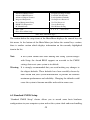
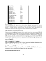
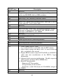
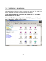
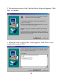
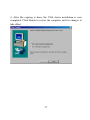
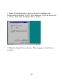
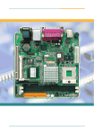
E-PoS 1000 Tec P3 System CHAPTER 1 INTRODUCTION Introduction This manual is suitable for E-PoS 1000 Tec P3 Mini Desk Top PC. The motherboard is all-in-one designed with 4 x AGP VGA, Audio sound and 10/100M Network chip build-in. This motherboard is design for both Mini Desk Top PC, which is a new designed with ATX structure. CHAPTER 2 GETTING STARTED On receiving your E-PoS 1000 Tec P3 Slim Size or Mini Desk Top PC, please check the following items: 1. What’s included Slim size or mini desk top case with ATX power supply installed. The Socket 370 all-in-one ATX type motherboard pre-installed inside the slim size or Mini Desk Top case. 2 slots PCI/ISA mixed Riser card pre-installed for E-POS 1000 TEC and 4 Slots PCI/ISA mixed riser card pre-installed for E-POS 1000 TEC One 40 pins flat cable for HDD and CD-ROM Pre-installed on the all-in-one ATX motherboard. One 34 pins flat cable for FDD pre-installed on the all-in-one ATX motherboard. One 10 pins flat cable for COM 1 port pre-installed. One 10 pins flat cable for COM 2 port pre-installed. One 10 pins flat cable for COM 3 port pre-installed. ( optional ) 1 One 10 pins flat cable for COM 4 port pre-installed. ( optional ) CPU and cooling fan with heat sink pre-install on the top of CPU. If you have ordered the system with CPU together. 2. 3. 4. 5. 168 pins DIMM memory from 32MB up to 1GB, if you have ordered the system with main memory together. One set screw pack which including the following: a. M3 X0.5 screws 12 pcs for FDD/CD-ROM and card installation. b. M3 X1 screws 4 pcs for HDD installation. User’s manual 1 pcs. Power cord. CD-ROM disk software driver Checking the AC input voltage before turn on the power switch. The AC input voltage can be switch from 110 Volts to 230 Volts or from 230 Volts to 110 Volts. The AC input voltage convert switch is located on the back side of the power supply. Please double check whether the AC input voltage is matching at your country or not. If it is the wrong voltage, please make the correct setting of this switch. Installing the CPU, if you order the system without CPU installed. The CPU type is socket 370 and it can be either Intel Tualatin Celeron speed up to 1.3Ghz or higher and Intel Tualatin Pentium III CPU speed up to 1.26Ghz or higher available in the market. Or Via C3 socket 370 CPU up to 1 Ghz or higher available in the market. Choose your CPU type and speed and make the correct CPU bus speed setting at SW1. Please refer to this manual on page NO.16 for the right CPU bus speed setting, please also make sure the correct CPU pin 1 direction before insert the CPU into the CPU socket. Please also install the CPU cooling fan on the top of the CPU. Installing the memory DIMM module, if you order the system without memory DIMM module installed. You can install the 168 pins DIMM memory module into location DIMM1 and DIMM2 on your motherboard. Since 168 pins DIMM module is 64 bits wide, therefore 1 piece of DIMM module may match a 64 bits system , the available memory module from the market will be from 32 MB up to 512MB , so , the maximum memory size will be up to 1 GB for total 2 Dimms installed. Installing the hard disk, if necessary. 2 Please refer to the step 8 of the Mini Desk Top PC system installation at page No. 7 of this manual for detailed hard disk installation. Installing the floppy disk, if necessary. Please refer to the step 9 of the Mini Desk Top PC system installation at page No. 8 of this manual for detailed floppy disk installation. 7. Installing the CD-ROM drive, if necessary. Please refer to the step 10 of the Mini Desk Top PC system installation at page No. 8 of this manual for detailed CD-ROM drive installation. Please refer to page No. 11 of this manual for the slim CD-ROM installation for E-POS 1000 TEC slim size PC. 8. Please refer to chapter 6 of this manual for the detailed BIOS CMOS SETUP. 9. Please Refer to chapter 7 for software driver installation for Via 4 in 1 driver , 4 x AGP VGA driver , 10/100 Mbit Lan driver and audio driver. 10. Installing the I/O card, if necessary. The E-POS 1000 TEC Slim Size PC has 2 I/O slots free and the E-POS 1000 TEC Mini Desk Top PC has 4 I/O Slots free for you to install any I/O cards. Please refer to step 19 of the Mini Desk Top PC system installation at page No. 9 of this manual for detailed I/O card installation. 6. CHAPTER 3 SPECIFICATION 3.2 E-PoS 1000 Tec PC specification! Case size : 32cm ( w ) x 33cm ( L ) x 8cm ( H ) Power supply : Internal power supply 235 watts 110V/230V switchable. Riser card : 2 slots PCI /ISA mixed. Drive bay : 1 x 3 1/2 " HDD + 1 x 3 1/2 " FDD or HDD + 3 1 x slim CD-ROM. Front panel: USB 1.1 x 2 ports ( share the same port as the back side ) or USB 2.0 x 2 ports ( optional ) and sound for Line out , Mic. Power switch , Reset switch , Power LED , HDD LED , Lan LED , sleep LED Back connector: Lan ,VGA , Printer , COM 1,2,3,4 , ( COM 3 & 4 optional ) , PS/2 keyboard , PS/2 mouse , USB 1.1 x 2 Following are the free slots condition with all the drives installed: a. One 3.5" HDD + one 3.5" FDD or HDD + one slim CD-ROM installed + 4 COMs installed, then you still have one PCI / ISA slot free. b. One 3.5" HDD + one 3.5" FDD or HDD + one slim CD-ROM installed + 2 COMs, then you still have two PCI /ISA slots free. 4 3.3 Motherboard Engineering Specifications Product Name Form Factor CPU Type CPU Voltage System Speed CPU External Clock Chipset BIOS Cache Digital I/O ( optional ) DiskOnChip Watchdog Timer ( optional ) UART/16550A (4Ports) ( COM 3 & 4 optional ) On Board VGA LCD interface ( optional ) LAN Sound Memory type SUPER I/O RTC/CMOS Battery Keyboard Controller EPP/ECP Local bus IDE(44 pin) USB 1.1 x 2 ports USB2.0x2 ports( optional ) Expansion Slot Board Size E-POS 1000 TEC Customer Size Socket 370 type , will support Intel’s Tualatin Pentium III & Celeron CPU and Via C3 CPU 1.1V~1.85V auto adjustable by CPU FSB speed 66/100/133 Mhz for Intel Pentium III CPU up to 1.26Ghz FC - PGA 2 ( Tualatin ) or Intel Celeron CPU up to 1.3Ghz FC- PGA 2 ( Tualatin ) or Via C3 CPU up to 1 Ghz. 66/100/133Mhz VIA Prosavage TwisterT(PN133T)+VT82C686B Chipset North Bridge:VT8606 552 PIN PBGA South Bridge:VT82C686B 352 PIN BGA Award BIOS Support ACPI Function 128K Level1 /64K Level2 (CPU integrated) 4 IN / 4 Out (TTL Level) optional Supports M-system 2MB~288MB DiskOnChip flash disk 16 Level ( optional ) COM1/3/4:RS232 w/16 Byte FIFO COM2:RS232/422/485 w/16 Byte FIFO(jumper selectable) Jumper selectable for +5V or + 12V at pin 9 of DB9 for COM 1/2/3/4 VT8606 with Integrated Savage4 AGP4x Graphic 8/16/32 MB frame buffer using system memory Integrated 2-channel 110MHZ LVDS interface Support 36 Bit TTL LCD Interface and 2 channel LVDS Realtek 8139C ( 8139C+ ) Single Chip Ethernet Controller 10/100 Base T support , RJ -45 port VT82C686B Built-in Sound controller + AC97 Codec VIA VT1612A (Lineout,Line-in,Mic.) 2 x 168-Pin DIMM 3.3V Max. up to 1GB Support PC100/PC133 DIMM Module VIA VT82C686B: IrDAx1 Parallel x1, Serial*2, FDC 2.88MB (3 Mode support ), Hardware monitor(3 thermal inputs,4 voltage monitor inputs, VID0-4,2 fan input WINBOND 83877:Serial*2 for COM 3 & 4 ( optional ) VT82C686B Built-in Lithium Battery VT82C686B Yes VT82C686B built-in , IDE1,2 (Ultra DMA 33/66/100) 2 ports, transfer rate up to 12Mb/s , in the back panel (and shared in the front panel for E-POS 1000 TEC ) 2 ports , transfer rate up to 400Mb /s , optional for E-POS 1000 TEC in the front panel and optional for E-POS 1000 TEC in the back side ( from the bracket ) EISA Slot (PCI/ISA) Customer Size 5 CHAPTER 4 INSTALLATION 4.2 E-POS 1000 TEC Slim Size PC System installation The E-POS 1000 TEC Slim Size PC system installation procedure will be similar to the E-POS 1000 TEC Mini Desk Top PC. Except the following devices need to do the special care. 1. Slim CD-ROM installation The slim CD-ROM needs to install a small PC board which converts the IDE interface of the slim CD-ROM to the standard IDE interface of the motherboard. Following is the block diagram of this converter board. J2 CON2 J1 JP1 z J2 : This connector is to connect the audio signal to the sound card. z J1 : This connector is to connect the power supply for the slim CDROM. z CON2 : This connector is to connect the IDE interface to the motherboard. z JP1 : This jumper is for master/slave select of the slim CD-ROM. For different brand of the slim CD-ROM, The master /slave selection method is different, so you have to check with the supplier how to set the slim CD-ROM to the slave device. Because if you installed the hard disk with the slim CD-ROM together with the same IDE cable that you have to set the slim CD-ROM to the slave condition. 6 Choose your slim CD-ROM vender and set the slim CD-ROM to the slave condition. Connects all the cables to J1, J2 and CON2 connectors. Step1. Installing the slim CD-ROM mounting bracket by screw in the 2 screws, on the HDD/FDD/CD-ROM holding bracket. Step2. Screw in the 2 M2 screws between the slim CD-ROM mounting bracket and the converter board. 7 CHAPTER 5 Motherboard diagram and jumper setting 5.1 E-POS 1000 TEC Motherboard Diagram & jumper location 8 5.2 E-POS 1000 TEC ALL-IN-ONE M/B Jumper setting 9 1. JP2 = CMOS jumper select 1-2 = Normal ( Default ) 2-3 = Clear CMOS 2. JP3, JP4, JP5: RS232/422/485 (COM2) Selection COM1 is fixed for RS-232 use only. COM2 is selectable for RS232, RS-422 and RS-485. The following table describes the jumper settings for COM2 selection. COM2 RS-232 RS-422 RS-485 JP5: JP5: JP5: 3-5 & 4-6 1-3 & 2-4 1-3 & 2-4 Setting JP4: JP4: JP4: (pin closed) 3-5 & 4-6 1-3 & 2-4 1-3 & 2-4 JP3: JP3: JP3: 1-2 3-4 5-6 Function Jumper 3. JP6 = Power pin select for COM1 at pin 9 of DB9 1-2 3-4 5-6 +5V Normal +12V 4. JP7 = Power pin select for COM2 at pin 9 of DB 1-2 +5V 10 3-4 5-6 Normal +12V 5. JP10 = Power pin select for COM3 at pin 9 of DB9 1-2 3-4 5-6 +5V Normal +12V 6. JP11 = Power pin select for COM4 at pin 9 of DB9 1-2 3-4 5-6 +5V Normal +12V 7. JP9 = DOC ( Disk On Chip ) address select jumper 1-2 : D0000 - D7FFF 2-3 : D8000 - DFFFF 8. JP12 : Lan 1 Enable /Disable jumper ON = Enable Lan 1 OFF = Disable Lan1 9. JP13 = Lan 2 Enable /Disable jumper ON = Enable Lan 2 OFF = Disable Lan 2 10. SW1: CPU Bus Speed Selector 11 Bus Speed SW1 off off on on 66MHz off off off on 100MHz off off off off 133MHz 11. 12. 13. 14. 15. 16. 17. 18. 19. 20. 21. 22. 23. 24. 25. 26. 27. 28. 29. 30. 31. 32. 33. Switch Setting J2 = Digital I/O connector ( 4 in & 4 out ) J4 = I/R connector J8 = COM 1 connector J9 = COM 2 connector COM3 = COM 3 connector COM4 = COM 4 connector J18 = System Fan / CPU Fan connector J20 = System Fan / CPU Fan connector J19 = Reset Switch J21 = Power Switch J10 = CD IN PW1 = ATX Power connector LED1 = HDD LED LED3 = Lan LED LED4 = Power LED J15 = Printer connector VGA1 = VGA monitor connector MS1 = P/S 2 Mouse connector Mic1 = Sound out put and Mic in connector KB1 = P/S2 Keyboard Connector Lan1 = Lan1 connector Lan2 = Lan2 connector USB1 = 2 x USB 1.1 connector 12 34. 35. 36. 37. 38. 39. 40. USB3 = 2 x USB 1.1 connector for E-POS 1000 TEC in the front panel USB2 = 2 x USB 2.0 connector IDE1 = Primary IDE Connector IDE2 = Secondary IDE Connector FDD = Floppy Disk Connector BAT1 = CMOS Battery DOC = Disk On Chip Socket Chapter 6 AWARD BIOS SETUP 6.1 BIOS Introduction The Award BIOS (Basic Input/Output System) installed in your computer system’s ROM supports Intel Pentium II/III processors. The BIOS provides critical lowlevel support for a standard device such as disk drives, serial ports and parallel ports. It also adds virus and password protection as well as special support for detailed fine-tuning of the chipset controlling the entire system. 6.2 BIOS Setup The Award BIOS provides a Setup utility program for specifying the system configurations and settings. The BIOS ROM of the system stores the Setup utility. When you turn on the computer, the Award BIOS is immediately activated. Pressing the <Del> key immediately allows you to enter the Setup utility. If you are a little bit late pressing the <Del> key, POST (Power On Self Test) will continue with its test routines, thus preventing you from invoking the Setup. If you still wish to enter Setup, restart the system by pressing the ”Reset” button or simultaneously pressing the <Ctrl>, <Alt> and <Delete> keys. You can also restart by turning the system Off and back On again. The following message will appear on the screen: Press <DEL> to Enter Setup In general, you press the arrow keys to highlight items, <Enter> to select, the <PgUp> and <PgDn> keys to change entries, <F1> for help and <Esc> to quit. When you enter the Setup utility, the Main Menu screen will appear on the screen. The Main Menu allows you to select from various setup functions and exit choices. Phoenix - AwardBIOS CMOS Setup Utility 13 Standard CMOS Features Advanced BIOS Features Advanced Chipset Features Integrated Peripherals Power Management Setup PnP/PCI Configurations PC Health Status Frequency/Voltage Control Load Fail-Safe Defaults Load Optimized Defaults Set Supervisor Password Set User Password Save & Exit Setup Exit Without Saving ESC : Quit F10 : Save & Exit Setup : Select Item Time, Date, Hard Disk Type… The section below the setup items of the Main Menu displays the control keys for this menu. At the bottom of the Main Menu just below the control keys section, there is another section which displays information on the currently highlighted item in the list. Note: If the system cannot boot after making and saving system changes with Setup, the Award BIOS supports an override to the CMOS settings that resets your system to its default. Warning: It is strongly recommended that you avoid making any changes to the chipset defaults. These defaults have been carefully chosen by both Award and your system manufacturer to provide the absolute maximum performance and reliability. Changing the defaults could cause the system to become unstable and crash in some cases. 6.3 Standard CMOS Setup “Standard CMOS Setup” choice allows you to record some basic hardware configurations in your computer system and set the system clock and error handling. 14 If the board is already installed in a working system, you will not need to select this option. You will need to run the Standard CMOS option, however, if you change your system hardware configurations, the onboard battery fails, or the configuration stored in the CMOS memory was lost or damaged. Phoenix - AwardBIOS CMOS Setup Utility Standard CMOS Features Date (mm:dd:yy) Thu, Mar 6 2003 Time (hh:mm:ss) 00 : 00 : 00 Menu Level Item Help IDE Primary Master IDE Primary Slave IDE Secondary Master IDE Secondary Slave Press Enter 13020 MB Press Enter None Press Enter None Press Enter None Press [Enter] to enter next page for detail hard drive settings Drive A Drive B 1.44M, 3.5 in. None Video Halt On EGA/VGA All, But Keyboard Base Memory 640K Extended Memory Total Memory 506880K 507904K At the bottom of the menu are the control keys for use on this menu. If you need any help in each item field, you can press the <F1> key. It will display the relevant information to help you. The memory display at the lower right-hand side of the menu is read-only. It will adjust automatically according to the memory changed. The following describes each item of this menu. Date The date format is: Day : Month : Date : Year : Sun to Sat 1 to 12 1 to 31 1994 to 2079 15 To set the date, highlight the “Date” field and use the PageUp/ PageDown or +/keys to set the current time. Time The time format is: Hour : Minute : Second : 00 to 23 00 to 59 00 to 59 To set the time, highlight the “Time” field and use the <PgUp>/ <PgDn> or +/keys to set the current time. IDE Primary HDDs / IDE Secondary HDDs The onboard PCI IDE connectors provide Primary and Secondary channels for connecting up to four IDE hard disks or other IDE devices. Each channel can support up to two hard disks; the first is the “Master” and the second is the “Slave” . Press <Enter> to configure the hard disk. The selections include Auto, Manual, and None. Select ‘Manual’ to define the drive information manually. You will be asked to enter the following items. CYLS : HEAD : PRECOMP : LANDZ : SECTOR : Number of cylinders Number of read/write heads Write precompensation Landing zone Number of sectors The Access Mode selections are as follows: Auto Normal (HD < 528MB) Large (for MS-DOS only) LBA (HD > 528MB and supports Logical Block Addressing) Drive A / Drive B These fields identify the types of floppy disk drive A or drive B that has been installed in the computer. The available specifications are: 360KB 1.2MB 720KB 1.44MB 2.88MB 5.25 in. 5.25 in. 3.5 in. 3.5 in. 3.5 in. 16 Halt On This field determines whether or not the system will halt if an error is detected during power up. The system boot will not be halted for any error No errors that may be detected. All errors Whenever the BIOS detects a non-fatal error, the system will stop and you will be prompted. All, But Keyboard The system boot will not be halted for a keyboard error; it will stop for all other errors All, But Diskette The system boot will not be halted for a disk error; it will stop for all other errors. All, But Disk/Key The system boot will not be halted for a keyboard or disk error; it will stop for all others. Select Display Device The options for this field are Auto, CRT, LCD, CRT+LCD, TV, and CRT+TV. 6.4 Advanced BIOS Features This section allows you to configure and improve your system and allows you to set up some system features according to your preference. Phoenix - AwardBIOS CMOS Setup Utility Advanced BIOS Features Virus Warning CPU Internal Cache External Cache CPU L2 Cache ECC Checking Quick Power On Self Test Disabled Enabled Enabled Enabled Enabled ITEM HELP Menu Level 17 Allows you choose the VIRUS warning feature for IDE Hard First Boot Device Second Boot Device Third Boot Device Boot Other Device Swap Floppy Drive Boot Up Floppy Seek Boot Up Numlock Status Gate A20 Option Typematic Rate Setting Typematic Rate (chars/Sec) Typematic Delay (Msec) Security Option OS Select For DRAM>64MB Video BIOS Shadow C8000-CBFFF Shadow CC000-CFFFF Shadow D0000-D3FFF Shadow D4000-D7FFF Shadow D8000-DBFFF Shadow DC000-DFFFF Shadow Small Logo (EPA) Show Floppy HDD-0 LS120 Enabled Disabled Enabled On Fast Disabled 6 250 Setup Non-OS2 Enabled Disabled Disabled Disabled Disabled Disabled Disabled Enabled Virus Warning This item protects the boot sector and partition table of your hard disk against accidental modifications. If an attempt is made, the BIOS will halt the system and display a warning message. If this occurs, you can either allow the operation to continue or run an anti-virus program to locate and remove the problem. CPU Internal Cache / External Cache Cache memory is additional memory that is much faster than conventional DRAM (system memory). CPUs from 486-type on up contain internal cache memory, and most, but not all, modern PCs have additional (external) cache memory. When the CPU requests data, the system transfers the requested data from the main DRAM into cache memory, for even faster access by the CPU. These items allow you to enable (speed up memory access) or disable the cache function. By default, these items are Enabled. CPU L2 Cache ECC Checking This field enables or disables the ECC (Error Correction Checking) checking of the CPU level-2 cache. The default setting is Enabled. Quick Power On Self Test When enabled, this field speeds up the Power On Self Test (POST) after the system is turned on. If it is set to Enabled, BIOS will skip some items. First/Second/Third Boot Device 18 These fields determine the drive that the system searches first for an operating system. The options available include Floppy, LS/ZIP, HDD-0, SCSI, CDROM, HDD-1, HDD-2, HDD-3, LAN and Disable. Boot Other Device These fields allow the system to search for an operating system from other devices other than the ones selected in the First/Second/Third Boot Device. Swap Floppy Drive This item allows you to determine whether or not to enable Swap Floppy Drive. When enabled, the BIOS swaps floppy drive assignments so that Drive A becomes Drive B, and Drive B becomes Drive A. By default, this field is set to Disabled. Boot Up Floppy Seek When enabled, the BIOS will seek whether or not the floppy drive installed has 40 or 80 tracks. 360K type has 40 tracks while 760K, 1.2M and 1.44M all have 80 tracks. Boot Up NumLock Status This allows you to activate the NumLock function after you power up the system. Gate A20 Option This field allows you to select how Gate A20 is worked. Gate A20 is a device used to address memory above 1 MB. Typematic Rate Setting When disabled, continually holding down a key on your keyboard will generate only one instance. When enabled, you can set the two typematic controls listed next. By default, this field is set to Disabled. Typematic Rate (Chars/Sec) When the typematic rate is enabled, the system registers repeated keystrokes speeds. Settings are from 6 to 30 characters per second. Typematic Delay (Msec) When the typematic rate is enabled, this item allows you to set the time interval for displaying the first and second characters. By default, this item is set to 250msec. Security Option 19 This field allows you to limit access to the System and Setup. The default value is Setup. When you select System, the system prompts for the User Password every time you boot up. When you select Setup, the system always boots up and prompts for the Supervisor Password only when the Setup utility is called up. OS Select for DRAM > 64MB This option allows the system to access greater than 64MB of DRAM memory when used with OS/2 that depends on certain BIOS calls to access memory. The default setting is Non-OS/2. Video BIOS Shadow This item allows you to change the Video BIOS location from ROM to RAM. Video Shadow will increase the video speed. C8000 - CBFFF Shadow/DC000 - DFFFF Shadow Shadowing a ROM reduces the memory available between 640KB to 1024KB. These fields determine whether or not optional ROM will be copied to RAM. Small Logo (EPA) Show This field enables the showing of the EPA logo located at the upper right of the screen during boot up. 6.5 Advanced Chipset Features This Setup menu controls the configuration of the chipset. Phoenix - AwardBIOS CMOS Setup Utility Advanced Chipset Features DRAM Timing By SPD DRAM Clock SDRAM Cycle Length Bank Interleave Memory Hole P2C/C2P Concurrency System BIOS Cacheable Video RAM Cacheable Frame Buffer Size AGP Aperture Size AGP-4X Mode Enabled Host CLK 3 Disabled Disabled Enabled Enabled Enabled 16M 64M Enabled 20 ITEM HELP Menu Level AGP Driving Control AGP Driving Value Select Display Device TV Type Panel Type OnChip USB USB Keyboard Support OnChip Sound OnChip Modem CPU to PCI Write Buffer PCI Dynamic Bursting PCI Master 0 WS Write PCI Delay Transaction PCI#2 Access #1 Retry AGP Master 1 WS Write AGP Master 1 WS Read Auto DA CRT JP NTSC 07 Enabled Enabled Auto Disabled Enabled Enabled Enabled Enabled Enabled Enabled Enabled DRAM Timing by SPD This field enables or disables the DRAM Timing based on SPD. DRAM Clock This item allows you to control the DRAM speed. The default setting is SDRAM Cycle Length When synchronous DRAM is install , the number of clock cycles of CAS latency depends on the DRAM timing. Do not reset this field from the default value specified by the system designer. The default setting is 3. Band Interleave The interleave number of internal banks, can be set to 2 way, 4 way interleave or disabled. For VCM and 16Mb type dram chips, the bank interleave is fixed at 2 way interleave. When the dram timing is selected by SPD, it will be set by the value on SPD if the RAM module (DDR or SDR). The default setting is Memory Hole It is recommended to leave as disabled, although enabling 15M-16M can help with sound issues. 21 P2C / C2P Concurrency Set to Disabled for best performance. You may set this to Enabled if you want any sort of system stability. System BIOS Cacheable The setting of Enabled allows caching of the system BIOS ROM at F000hFFFFFh, resulting in better system performance. However, if any program writes to this memory area, a system error may result. Video RAM Cacheable Selecting Enabled allows caching of the video RAM , resulting in better system performance. However , if any program is written to this memory area , a system error may result. The default setting is Frame Buffer Size This item allows you to control the VGA frame buffer size. The default setting is AGP Aperture Size The field sets aperture size of the graphics. The aperture is a portion of the PCI memory address range dedicated for graphics memory address space. Host cycles that hit the aperture range are forwarded to the AGP without any translation. The default setting is 64M. AGP-4X Mode The field enables or disables the AGP-4X mode of the integrated VGA function. AGP Driving Control This BIOS function allows you to adjust the control of the AGP driving force. It is set to Auto by default. AGP Driving Value This item enables an end user to manually select the AGP output buffer drive strength. KEY in a HEX number: Min=0000, Max=00FF. Select Display Device TV Type 22 Panel Type This field sets the panel type that is supported by the system. Below are the selections for the different panel types: Panel Type 0 640x480 18bit TFT Panel Type 1 800x600 18bit TFT Panel Type 2 1024x768 36bit TFT Panel Type 3 1280x1024 36bit TFT Panel Type 4 640x480 16bit DSTN Panel Type 5 800x600 16bit DSTN Panel Type 6 1024x768 16bit DSTN Panel Type 7 1024x768 18bit 1CH LVDS Panel Type 8 640x480 18bit TFT Panel Type 9 800x600 18bit TFT Panel Type A 1024x768 18bit TFT Panel Type B 1280x1024 18bit TFT Panel Type C 1400x1050 36bit 2CH LVDS Panel Type D 800x600 16bit DSTN Panel Type E 1024x768 16bit DSTN Panel Type F 1280x1024 16bit DSTN OnChip USB The default setting is Enabled to enable the USB function on board. USB Keyboard Support Enable this if you are using a USB keyboard. OnChip Sound This field can be set as Auto or disabled. OnChip Modem This field can be set as Auto or disabled. CPU to PCI Write Buffer This controls the CPU write buffer to the PCI bus. If this buffer is disabled, the CPU writes directly to the PCI bus. The default setting is Enabled. PCI Dynamic Bursting 23 This option controls the PCI write buffer. If this is enabled, then every write transaction on the PCI bus goes straight to the write buffer. Burst transactions are then sent on their way as soon as there are enough to send in a single burst. PCI Master 0 WS Write This function determines whether there’s a delay before any writes to the PCI bus. If this is enabled, then writes to the PCI bus are executed immediately (with zero wait states), as soon as the PCI bus is ready to receive data. But if it is disabled, then every write transaction to the PCI bus is delayed by one wait state. It’s recommended to enable this for faster PCI performance. PCI Delay Transaction The chipset has an embedded 32-bit posted write buffer to support delay transactions cycles. Select Enabled to support compliance with PCI specification version 2.1. PCI#2 Access #1 Retry This BIOS feature is linked to the CPU to PCI Write Buffer. Normally, the CPU to PCI Write Buffer is enabled. All writes to the PCI bus are, as such, immediately written into the buffer, instead of the PCI bus. This frees up the CPU from waiting till the PCI bus is free. The data are then written to the PCI bus when the next PCI bus cycle starts. AGP Master 1 WS Write/Read When enabled a single wait state is used when writing/reading to the AGP bus. When disabled a 2 wait state is used. For optimal performance set this to enabled. For improved stability set it to disabled. 6.6 Integrated Peripherals Phoenix - AwardBIOS CMOS Setup Utility Integrated Peripherals OnChip IDE Channel 0 OnChip IDE Channel 1 IDE Prefetch Mode Primary Master PIO Primary Slave PIO Secondary Master PIO Enabled Enabled Enabled Auto Auto Auto ITEM HELP Menu Level 24 Secondary Slave PIO Primary Master UDMA Primary Slave UDMA Secondary Master UDMA Secondary Slave UDMA Init Display First IDE HDD Block Mode Onboard FDD Controller Onboard Serial Port 1 Onboard Serial Port 2 UART 2 Mode IR Function Duplex TX , RX inverting enable Onboard Parallel Port Onboard Parallel Mode ECP Mode Use DMA Parallel Port EPP Type Onboard Serial Port 3 Serial Port 3 Use IRQ Onboard Serial Port 4 Serial Port 4 Use IRQ Onboard Legacy Audio Sound Blaster SB I/O Base Address SB IRQ Select SB DMA Select MPU-401 MPU-401 I/O Address Game Port (200-207H) Auto Auto Auto Auto Auto PCI Slot Enabled Enabled 3F8/IRQ4 2F8/IRQ3 Standard Half No, Yes 378/IRQ7 Normal 3 EPP 1.9 3E8H IRQ5 2E8H IRQ10 Enabled Disabled 220H IRQ 5 DMA 1 Disabled 330-333H Disabled OnChip IDE Channel 0 / 1 The integrated peripheral controller contains an IDE interface with support for two IDE channels. Select Enabled to activate each channel separately. IDE Prefetch Mode These field enables/disables the prefetch buffers in the PCI IDE controller. The prefetch buffers are used as a temporary storage place as data is transferred from one location to another. IDE Primary/Secondary Master/Slave PIO These fields allow your system hard disk controller to work faster. Rather than have the BIOS issue a series of commands that transfer to or from the disk drive, PIO (Programmed Input/Output) allows the BIOS to communicate with the controller and CPU directly. The system supports five modes, numbered from 0 (default) to 4, which primarily differ in timing. When Auto is selected, the BIOS will select the best available mode. 25 IDE Primary/Secondary Master/Slave UDMA These fields allow your system to improve disk I/O throughput to 33Mb/sec with the Ultra DMA/33 feature. The options are Auto and Disabled. Init Display First This field allows the system to initialize first the VGA card on chip or the display on the PCI Slot. By default, the PCI Slot VGA is initialized first. IDE HDD Block Mode This field allows your hard disk controller to use the fast block mode to transfer data to and from your hard disk drive. Onboard FDD Controller Select Enabled if your system has a floppy disk controller installed on the Embedded Board and you wish to use it. If you install an add-in FDC or the system has no floppy drive, select Disabled in this field. This option allows you to select the onboard FDD port. Onboard Serial/Parallel Port/IRQ These fields allow you to select the onboard serial and parallel ports and their addresses. The default values for these ports are: Serial Port 1 3F8/IRQ4 Serial Port 2 2F8/IRQ3 Serial Port 3 3E8H/IRQ5 Serial Port 4 2E8H/IRQ10 Parallel Port 378H/IRQ7 UART 2 Mode This item allows you to determine which Infra Red (IR) function of onboard I/O chip. The options are Standard, IrDA, and ASKIR. IR Function Duplex This item allows you to select the IR half/full duplex function. The default setting is TX,RX inverting enable 26 This item allows you to enable the TX , RX inverting which depends on different H/W requirement. This field in not recommended to change its default setting for avoiding any error in your system. The default setting is Onboard Parallel Mode There are four options the setting ECP Mode Use DMA When the onboard parallel port is set to ECP mode, the parallel port has the option to use DMA Parallel Port EPP Type This field allows you to determine parallel port mode function. SPP Standard Printer Port EPP Enhanced Parallel Port ECP Extended Capabilities Port Onboard Legacy Audio Enable or disable the on board legacy audio with this option. If enabled, some audio options will appear. Sound Blaster This item enabled/disabled the onboard Sound Blaster. The default setting is SB I/O Base Address This item selects the Sound Blaster I/O Base Address. The default setting is SB IRQ Select This item selects the Sound Blaster IRQ. The default setting is SB DMA Select This item selects the Sound Blaster DMA. The default setting is MPU-401 27 This item enabled/disabled on-board MPU-401. The default setting is MPU-401 I/O Address This item selects MPU-401 I/O Address. The default setting is Game Port (200-207H) This item selects the Game Port. The default setting is 6.7 Power Management Setup The Power Management Setup allows you to save energy of your system effectively. Phoenix - AwardBIOS CMOS Setup Utility Power Management Setup ACPI Function Enabled Power Management ACPI Suspend Type PM Control by APM Video Off Option Video Off Method Modem Use IRQ Press Enter S1(POS) Yes Suspend -> Off Soft-Off by PWRBTN State After Power Failure Wake Up Events ITEM HELP Menu Level V/H Sync + Blank 3 Instant-Off On Press Enter Phoenix - AwardBIOS CMOS Setup Utility Power Management Setup Power Management User Define HDd Power Down Doze Mode Suspend Mode Disabled ITEM HELP Menu Level Disabled Disabled Phoenix - AwardBIOS CMOS Setup Utility IRQ/Event Activity Detect VGA OFF LPT & COM HDD & FDD LPT / COM ON ITEM HELP PCI Master Modem Ring Resume RTC Alarm Resume Date (of Month) OFF Disabled Disabled 0 Resume Time (hh:mm:ss) Primary INTR IRQs Activity Monitoring 0 : 0 : 0 ON Menu Level Press Enter Phoenix - AwardBIOS CMOS Setup Utility IRQs Activity Monitoring 28 IRQ3 (COM 2 ) Enabled IRQ4 IRQ5 IRQ6 IRQ7 IRQ8 (COM 1 ) (LPT 2 ) (Floppy Disk ) (LPT 1 ) (RTC Alarm ) Enabled IRQ9 IRQ10 IRQ11 IRQ12 IRQ13 IRQ14 (IRQ2 Redir ) (Reserved ) (Reserved ) (PS/2 Mouse ) (Coprocessor ) (Hard Disk ) IRQ15 (Reserved ) ITEM HELP Menu Level Enabled Enabled Enabled Disabled Disabled Disabled Disabled Enabled Enabled Enabled Disabled ACPI Function Use this option to enable or disable the ACPI function Power Management When you press Enter while selecting this field, the menu for Power Management appears. The following are the fields in this menu. Power Management This field allows you to select the type of power saving management modes. There are four selections for Power Management. Min. Saving Max. Saving User Define (Default) Minimum power management Maximum power management. Each of the ranges is from 1 min. to 1hr. Except for HDD Power Down which ranges from 1 min. to 15 min. Under this option, you can also configure other features such HDD Power Down, Doze Mode and Suspend Mode. HDD Power Down After the selected period of drive inactivity, the hard disk drive powers down while all other devices remain active. Control of this mode is independent of the Power Management mode selected previously. Doze Mode After the selected period of system inactivity, the CPU clock runs at slower speed while all other devices still operate at full speed. 29 Suspend Mode This option decides when to shutdown video for power saving. You can select it as always on or turn off video when system enters suspend mode. ACPI Suspend Type Use this item to define how your system suspends. If set to S1(POS) (default), the suspend mode is equivalent to a software power down. If set to S3(STR), the suspend mode is a suspend to RAM the system shuts down with the exception of a refresh current to the system memory. PM Control by APM If Advanced Power Management (APM) is installed on your system, selecting Yes gives better power savings. Video Off Option This option decides when to shutdown video for power saving. You can select it as always on or turn off video when system enters suspend mode. Video Off Method This field defines the Video Off features. There are three options. V/H SYNC + Blank Default setting, blank the screen and turn off vertical and horizontal scanning. DPMS Allows the BIOS to control the video display card if it supports the DPMS feature. Blank Screen This option only writes blanks to the video buffer. Modem Use IRQ This field sets the IRQ used by the Modem. By default, the setting is 3. Soft-Off by PWRBTN This field defines the power-off mode when using an ATX power supply. The Instant Off mode allows powering off immediately upon pressing the power button. In the Delay 4 Sec mode, the system powers off when the power button is pressed for more than four seconds or enters the suspend mode when pressed for less than 4 seconds. The default value is Instant Off. State After Power Failure This item to set the ATX power supply status when power resume after unexpected power fail. When off is selected, power supply will maintain on soft-off status, when power is resume. When on is selected, power supply will turn on, and when 30 Auto is selected, power supply will maintain on the status before unexpected power fail. The default is Wake Up Events The HDD, FDD, COM, LPT Ports, and PCI PIRQ are I/O events which can prevent the system from entering a power saving mode or can awaken the system from such a mode. When an I/O device wants to gain the attention of the operating system, it signals this by causing an IRQ to occur. When the operating system is ready to respond to the request, it interrupts itself and performs the service. 6.8 PNP/PCI Configurations This option configures the PCI bus system. All PCI bus systems on the system use INT#, thus all installed PCI cards must be set to this value. Phoenix - AwardBIOS CMOS Setup Utility PnP/PCI Configurations PNP OS Install No Reset Configuration Data Disabled Menu Level Resources Controlled By Auto [ESCD] Press Enter Press Enter Default is Disabled. Select Enabled to reset Extended System Configuration Data (ESCD) when you exit Setup if you have installed a new add-on and the system reconfiguration has caused such a serious conflict that the OS cannot boot IRQ Resources DMA Resources PCI/VGA Palette Snoop Assign IRQ for VGA Assign IRQ for USB ITEM HELP Disabled Disabled Disabled PNP OS Install Enable the PNP OS Install option if it is supported by the operating system installed. The default value is No. Reset Configuration Data This field allows you to determine whether to reset the configuration data or not. The default value is Disabled. Resources Controlled by This PnP BIOS can configure all of the boot and compatible devices automatically with the use of a use a PnP operating system such as Windows 95. 31 IRQ/DMA Resources When resources are controlled manually, assign each system interrupt a type, depending on the type of device using the interrupt. IRQ3/4/5/7/9/10/11/12/14/15 assigned to This item allows you to determine the IRQ assigned to the ISA bus and is not available to any PCI slot. Legacy ISA for devices is compliant with the original PC AT bus specification ; PCI/ISA PnP (default) for devices is compliant with the Plug-and Play standard whether designed for PCI or ISA bus architecture. DMA 0/1/3/5/6/7 assigned to When resources are controlled manually, assign each system DMA channel as one of the following types, depending on the type of device using the interrupt : Legacy ISA Devices compliant with the original PC AT bus specification, requiring a specific interrupt (such as IRQ4 for serial port 1). PCI/ISA PnP(default) Devices compliant with the Plug-and-Play standard , whether designed for PCI or ISA bus architecture. PCI/VGA Palette Snoop Some non-standard VGA display cards may not show colors properly. This field allows you to set whether or not MPEG ISA/VESA VGA cards can work with PCI/VGA. When this field is enabled, a PCI/VGA can work with an MPEG ISA/VESA VGA card. When this field is disabled, a PCI/VGA cannot work with an MPEG ISA/VESA card. Assign IRQ for VGA/USB By default, this fields are Enabled. 6.9 PC Health Status This section shows the parameters in determining the PC Health Status. These parameters include temperatures, fan speeds and voltages. Phoenix - AwardBIOS CMOS Setup Utility PC Health Status CPU Warning Temperature 60 C/140 F Current CPU Temp. 34 C/95 F 28 C/82 F 4166 RPM 0 RPM 1.50V Current System Temp. Current CPUFAN1 Speed Current CPUFAN2 Speed Vcore 2.5(V) 3.3(V) 2.48V 3.28V 32 ITEM HELP 5(V) 12(V) 5.20V 11.94V CPU Warning Temperature This field sets the temperature threshold that when reached, the system would give an audible warning. Current CPU Temp Displays the current CPU temperature. Current System Temp. Displays the current system temperature. Current CPUFAN1/2/ Speed 33 Displays the current speed of the CPU, chassis , and power fan speed in RPMs. Vcore The voltage level of the CPU(Vcore). 6.10 Frequency/Voltage Control This section shows the user how to configure the processor frequency. Phoenix - AwardBIOS CMOS Setup Utility Frequency/Voltage Control VIA C3 Clock Ratio Default Auto Detect DIMM/PCI Clk Spread Spectrum CPU Host Clock (CPU/PCI) Enabled Disabled ITEM HELP Default VIA C3 Clock Ratio Auto Detect DIMM/PCI Clk This field enables or disables the auto detection of the DIMM/PCI clock. The default setting is Disabled. Spread Spectrum This field sets the value of the spread spectrum. The default setting is Disabled. This field is for CE testing use only. CPU Host Clock (CPU/PCI) The Host CPU/PCI Clock has a default setting of Default which automatically detects the systems host CPU clock and PCI clock. You can also use this parameter to over clock your system. However, it is important to note that over clocking the system/CPU can cause your system to become unstable or crash. 6.11 Load Fail-Safe Defaults 34 This option allows you to load the troubleshooting default values permanently stored in the BIOS ROM. These default settings are non-optimal and disable all high-performance features. 6.12 Load Setup Defaults This option allows you to load the default values to your system configuration. These default settings are optimal and enable all high performance features. 6.13 Set Supervisor/User Password These two options set the system password. Supervisor Password sets a password that will be used to protect the system and Setup utility. User Password sets a password that will be used exclusively on the system. To specify a password, highlight the type you want and press <Enter>. The Enter Password: message prompts on the screen. Type the password, up to eight characters in length, and press <Enter>. The system confirms your password by asking you to type it again. After setting a password, the screen automatically returns to the main screen. To disable a password, just press the <Enter> key when you are prompted to enter the password. A message will confirm the password to be disabled. Once the password is disabled, the system will boot and you can enter Setup freely. 6.14 Save & Exit Setup This option allows you to determine whether or not to accept the modifications. If you type “ Y” , you will quit the setup utility and save all changes into the CMOS memory. If you type “ N” , you will return to Setup utility. 6.15 Exit Without Saving Select this option to exit the Setup utility without saving the changes you have made in this session. Typing “ Y” will quit the Setup utility without saving the modifications. Typing “ N” will return you to Setup utility. Quit without saving (Y/N)? Y This allows you to exit Setup without storing in CMOS any change. The previous selections remain in effect. This exits the Setup utility and restarts your computer. 6.16 POST Messages During the Power On Self-Test (POST), if the BIOS detects an error requiring you to do something to fix, it will either sound a beep code or display a message. 35 If a message is displayed, it will be accompanied by: PRESS F1 TO CONTINUE, CTRL-ALT-ESC OR DEL TO ENTER SETUP POST Beep Currently there are two kinds of beep codes in BIOS. This code indicates that a video error has occurred and the BIOS cannot initialize the video screen to display any additional information. This beep code consists of a single long beep followed by two short beeps. The other code indicates that your DRAM error has occurred. This beep code consists of a single long beep repeatedly. Error Messages One or more of the following messages may be displayed if the BIOS detects an error during the POST. This list includes messages for both the ISA and the EISA BIOS. CMOS BATTERY HAS FAILED CMOS battery is no longer functional. It should be replaced. CMOS CHECKSUM ERROR Checksum of CMOS is incorrect. This can indicate that CMOS has become corrupt. This error may have been caused by a weak battery. Check the battery and replace if necessary. DISK BOOT FAILURE, INSERT SYSTEM DISK AND PRESS ENTER No boot device was found. This could mean that either a boot drive was not detected or the drive does not contain proper system boot files. Insert a system disk into Drive A: and press <Enter>. If you assumed the system would boot from the hard drive, make sure the controller is inserted correctly and all cables are properly attached. Also be sure the disk is formatted as a boot device. Then reboot the system. DISKETTE DRIVES OR TYPES MISMATCH ERROR - RUN SETUP Type of diskette drive installed in the system is different from the CMOS definition. Run Setup to reconfigure the drive type correctly. DISPLAY SWITCH IS SET INCORRECTLY 36 Display switch on the motherboard can be set to either monochrome or color. This indicates the switch is set to a different setting than indicated in Setup. Determine which setting is correct, and then either turn off the system and change the jumper, or enter Setup and change the VIDEO selection. DISPLAY TYPE HAS CHANGED SINCE LAST BOOT Since last powering off the system, the display adapter has been changed. You must configure the system for the new display type. EISA Configuration Checksum Error PLEASE RUN EISA CONFIGURATION UTILITY The EISA non-volatile RAM checksum is incorrect or cannot correctly read the EISA slot. This can indicate either the EISA non-volatile memory has become corrupt or the slot has been configured incorrectly. Also be sure the card is installed firmly in the slot. EISA Configuration Is Not Complete PLEASE RUN EISA CONFIGURATION UTILITY The slot configuration information stored in the EISA non-volatile memory is incomplete. Note: When either of these errors appear, the system will boot in ISA mode, which allows you to run the EISA Configuration Utility. ERROR ENCOUNTERED INITIALIZING HARD DRIVE Hard drive cannot be initialized. Be sure the adapter is installed correctly and all cables are correctly and firmly attached. Also be sure the correct hard drive type is selected in Setup. ERROR INITIALIZING HARD DISK CONTROLLER Cannot initialize controller. Make sure the cord is correctly and firmly installed in the bus. Be sure the correct hard drive type is selected in Setup. Also check to see if any jumper needs to be set correctly on the hard drive. FLOPPY DISK CNTRLR ERROR OR NO CNTRLR PRESENT 37 Cannot find or initialize the floppy drive controller. make sure the controller is installed correctly and firmly. If there are no floppy drives installed, be sure the Diskette Drive selection in Setup is set to NONE. Invalid EISA Configuration PLEASE RUN EISA CONFIGURATION UTILITY The non-volatile memory containing EISA configuration information was programmed incorrectly or has become corrupt. Re-run EISA configuration utility to correctly program the memory. NOTE: When this error appears, the system will boot in ISA mode, which allows you to run the EISA Configuration Utility. KEYBOARD ERROR OR NO KEYBOARD PRESENT Cannot initialize the keyboard. Make sure the keyboard is attached correctly and no keys are being pressed during the boot. If you are purposely configuring the system without a keyboard, set the error halt condition in Setup to HALT ON ALL, BUT KEYBOARD. This will cause the BIOS to ignore the missing keyboard and continue the boot. Memory Address Error at ... Indicates a memory address error at a specific location. You can use this location along with the memory map for your system to find and replace the bad memory chips. Memory parity Error at ... Indicates a memory parity error at a specific location. You can use this location along with the memory map for your system to find and replace the bad memory chips. MEMORY SIZE HAS CHANGED SINCE LAST BOOT 38 Memory has been added or removed since the last boot. In EISA mode use Configuration Utility to reconfigure the memory configuration. In ISA mode enter Setup and enter the new memory size in the memory fields. Memory Verify Error at ... Indicates an error verifying a value already written to memory. Use the location along with your system’s memory map to locate the bad chip. OFFENDING ADDRESS NOT FOUND This message is used in conjunction with the I/O CHANNEL CHECK and RAM PARITY ERROR messages when the segment that has caused the problem cannot be isolated. OFFENDING SEGMENT: This message is used in conjunction with the I/O CHANNEL CHECK and RAM PARITY ERROR messages when the segment that has caused the problem has been isolated. PRESS A KEY TO REBOOT This will be displayed at the bottom screen when an error occurs that requires you to reboot. Press any key and the system will reboot. PRESS F1 TO DISABLE NMI, F2 TO REBOOT When BIOS detects a Non-maskable Interrupt condition during boot, this will allow you to disable the NMI and continue to boot, or you can reboot the system with the NMI enabled. RAM PARITY ERROR - CHECKING FOR SEGMENT ... Indicates a parity error in Random Access Memory. Should Be Empty But EISA Board Found PLEASE RUN EISA CONFIGURATION UTILITY A valid board ID was found in a slot that was configured as having no board ID. NOTE; When this error appears, the system will boot in ISA mode, which allows you to run the EISA Configuration Utility. 39 Should Have EISA Board But Not Found PLEASE RUN EISA CONFIGURATION UTILITY The board installed is not responding to the ID request, or no board ID has been found in the indicated slot. NOTE: When this error appears, the system will boot in ISA mode, which allows you to run the EISA Configuration Utility. Slot Not Empty Indicates that a slot designated as empty by the EISA Configuration Utility actually contains a board. NOTE: When this error appears, the system will boot in ISA mode, which allows you to run the EISA Configuration Utility. SYSTEM HALTED, (CTRL-ALT-DEL) TO REBOOT ... Indicates the present boot attempt has been aborted and the system must be rebooted. Press and hold down the CTRL and ALT keys and press DEL. Wrong Board In Slot PLEASE RUN EISA CONFIGURATION UTILITY The board ID does not match the ID stored in the EISA non-volatile memory. NOTE: When this error appears, the system will boot in ISA mode, which allows you to run the EISA Configuration Utility. FLOPPY DISK(S) fail (80) o Unable to reset floppy subsystem. 40 FLOPPY DISK(S) fail (40) o Floppy Type mismatch. Hard Disk(s) fail (80) o HDD reset failed Hard Disk(s) fail (40) o HDD controller diagnostics failed. Hard Disk(s) fail (20) o HDD initialization error. Hard Disk(s) fail (10) o Unable to recalibrate fixed disk. Hard Disk(s) fail (08) o Sector Verify failed. Keyboard is locked out - Unlock the key. BIOS detect the keyboard is locked. P17 of keyboard controller is pulled low. Keyboard error or no keyboard present. Cannot initialize the keyboard. Make sure the keyboard is attached correctly and no keys are being pressed during the boot. Manufacturing POST loop. System will repeat POST procedure infinitely while the P15 of keyboard controller is pull low. This is also used for M/B burn in test. BIOS ROM checksum error - System halted. The checksum of ROM address F0000H-FFFFFH is bad. Memory test fail. BIOS reports the memory test fail if the onboard memory is tested error. 6.17 POST Codes POST (hex) Description CFh Test CMOS R/W functionality. C0h Early chipset initialization: Disable shadow RAM -Disable L2 cache (socket 7 or below) -Program basic chipset registers 41 POST (hex) C1h C3h C5h 0h1 02h 03h 04h 05h 06h 07h 08h 09h 0Ah 0Bh 0Ch 0Dh 0Eh 0Fh 10h 11h 12h Description Detect memory -Auto-detection of DRAM size, type and ECC. -Auto-detection of L2 cache (socket 7 or below) Expand compressed BIOS code to DRAM Call chipset hook to copy BIOS back to E000 & F000 shadow RAM. Expand the Xgroup codes locating in physical address 1000:0 Reserved Initial Superio_Early_Init switch. Reserved 1. Blank out screen 2. Clear CMOS error flag Reserved 1. Clear 8042 interface 2. Initialize 8042 self-test 1. Test special keyboard controller for Winbond 977 series Super I/O chips. 2. Enable keyboard interface. Reserved 1. Disable PS/2 mouse interface (optional). 2. Auto detect ports for keyboard & mouse followed by a port & interface swap (optional). 3. Reset keyboard for Winbond 977 series Super I/O chips. Reserved Reserved Reserved Test F000h segment shadow to see whether it is R/W-able or not. If test fails, keep beeping the speaker. Reserved Auto detect flash type to load appropriate flash R/W codes into the run time area in F000 for ESCD & DMI support. Reserved Use walking 1’s algorithm to check out interface in CMOS circuitry. Also set real-time clock power status, and then check for override. 42 POST (hex) 13h 14h 15h 16h 17h 18h 19h 1Ah 1Bh 1Ch 1Dh 1Eh 1Fh 20h 21h 22h 23h 24h 25h Description Reserved Program chipset default values into chipset. Chipset default values are MODBIN able by OEM customers. Reserved Initial Early_Init_Onboard_Generator switch. Reserved Detect CPU information including brand, SMI type (Cyrix or Intel) and CPU level (586 or 686). Reserved Reserved Initial interrupts vector table. If no special specified, all H/W interrupts are directed to SPURIOUS_INT_HDLR & S/W interrupts to SPURIOUS_soft _HDLR. Reserved Initial EARLY_PM_INIT switch. Reserved Load keyboard matrix (notebook platform) Reserved HPM initialization (notebook platform) Reserved 1. Check validity of RTC value: e.g. a value of 5Ah is an invalid value for RTC minute. 2. Load CMOS settings into BIOS stack. If CMOS checksum fails, use default value instead. 3. Prepare BIOS resource map for PCI & PnP use. If ESCD is valid, take into consideration of the ESCD’s legacy information. 4. Onboard clock generator initialization. Disable respective clock resource to empty PCI & DIMM slots. 5. Early PCI initialization: -Enumerate PCI bus number -Assign memory & I/O resource -Search for a valid VGA device & VGA BIOS, and put it into C000:0. Reserved Reserved 43 POST (hex) 26h 27h 28h 29h 2Ah 2Bh 2Ch 2Dh 2Eh 2Fh 30h 31h 32h 33h 34h 35h 36h 37h 38h 39h 3Ah 3Bh 3Ch 3Dh 3Eh 3Fh 40h 41h Description Reserved Initialize INT 09 buffer Reserved 1. Program CPU internal MTRR (P6 & PII) for 0-640K memory address. 2. Initialize the APIC for Pentium class CPU. 3. Program early chipset according to CMOS setup. Example: onboard IDE controller. 4. Measure CPU speed. 5. Invoke video BIOS. Reserved Reserved Reserved 1. Initialize multi-language 2. Put information on screen display, including Award title, CPU type, CPU speed …. Reserved Reserved Reserved Reserved Reserved Reset keyboard except Winbond 977 series Super I/O chips. Reserved Reserved Reserved Reserved Reserved Reserved Reserved Reserved Test 8254 Reserved Test 8259 interrupt mask bits for channel 1. Reserved Test 8259 interrupt mask bits for channel 2. Reserved 44 POST (hex) 42h 43h 44h 45h 46h 47h 48h 49h 4Ah 4Bh 4Ch 4Dh 4Eh 4Fh 50h 51h 52h 53h 54h 55h 56h 57h 58h 59h 5Ah Description Reserved Test 8259 functionality. Reserved Reserved Reserved Initialize EISA slot Reserved 1.Calculate total memory by testing the last double word of each 64K page 2.Program writes allocation for AMD K5 CPU. Reserved Reserved Reserved Reserved 1. Program MTRR of M1 CPU 2. Initialize L2 cache for P6 class CPU & program CPU with proper cacheable range. 3. Initialize the APIC for P6 class CPU. 4. On MP platform, adjust the cacheable range to smaller one in case the cacheable ranges between each CPU are not identical. Reserved Initialize USB Reserved Test all memory (clear all extended memory to 0) Reserved Reserved Display number of processors (multi-processor platform) Reserved 1. Display PnP logo 2. Early ISA PnP initialization -Assign CSN to every ISA PnP device. Reserved Initialize the combined Trend Anti-Virus code. Reserved 45 POST (hex) 5Bh 5Ch 5Dh 5Eh 5Fh 60h 61h 62h 63h 64h 65h 66h 67h 68h 69h 6Ah 6Bh 6Ch 6Dh 6Eh 6Fh 70h 71h 72h Description (Optional Feature) Show message for entering AWDFLASH.EXE from FDD (optional) Reserved 1. Initialize Init_Onboard_Super_IO switch. 2. Initialize Init_Onbaord_AUDIO switch. Reserved Reserved Okay to enter Setup utility; i.e. not until this POST stage can users enter the CMOS setup utility. Reserved Reserved Reserved Reserved Initialize PS/2 Mouse Reserved Prepare memory size information for function call: INT 15h ax=E820h Reserved Turn on L2 cache Reserved Program chipset registers according to items described in Setup & Auto-configuration table. Reserved 1. Assign resources to all ISA PnP devices. 2. Auto assign ports to onboard COM ports if the corresponding item in Setup is set to “ AUTO” . Reserved 1. Initialize floppy controller 2. Set up floppy related fields in 40:hardware. Reserved Reserved Reserved 46 POST (hex) 73h 74h 75h 76h 77h 78h 79h 7Ah 7Bh 7Ch 7Dh 7Eh 7Fh 80h 81h 82h 83h 84h 85h Description (Optional Feature) Enter AWDFLASH.EXE if : -AWDFLASH is found in floppy drive. -ALT+F2 is pressed Reserved Detect & install all IDE devices: HDD, LS120, ZIP, CDROM….. Reserved Detect serial ports & parallel ports. Reserved Reserved Detect & install co-processor Reserved Reserved Reserved Reserved 1. Switch back to text mode if full screen logo is supported. -If errors occur, report errors & wait for keys -If no errors occur or F1 key is pressed to continue: Clear EPA or customization logo. Reserved Reserved 1. Call chipset power management hook. 2. Recover the text fond used by EPA logo (not for full screen logo) 3. If password is set, ask for password. Save all data in stack back to CMOS Initialize ISA PnP boot devices 1. USB final Initialization 2. NET PC: Build SYSID structure 3. Switch screen back to text mode 4. Set up ACPI table at top of memory. 5. Invoke ISA adapter ROMs 6. Assign IRQs to PCI devices 7. Initialize APM 8. Clear noise of IRQs. 47 POST (hex) 86h 87h 88h 89h 90h 91h 92h 93h 94h 95h 96h FFh Description Reserved Reserved Reserved Reserved Reserved Reserved Reserved Read HDD boot sector information for Trend Anti-Virus code 1. Enable L2 cache 2. Program boot up speed 3. Chipset final initialization. 4. Power management final initialization 5. Clear screen & display summary table 6. Program K6 write allocation 7. Program P6 class write combining 1. Program daylight saving 2. Update keyboard LED & typematic rate 1. Build MP table 2. Build & update ESCD 3. Set CMOS century to 20h or 19h 4. Load CMOS time into DOS timer tick 5. Build MSIRQ routing table. Boot attempt (INT 19h) 48 Chapter 7 Driver Installation 7.1 VIA 4 in 1 Drivers Installation Follow the steps below to proceed with the VIA 4 in 1 drivers installation. 1. In your Windows operating system, click My ComputerÆ Compact DiscÆ MFI-686Æ VIA4in1Æ4IN1Æ Setup 49 50 2. When the Welcome screen appears, click Next. 3. Click Next to agree with the license agreement statement and to continue. 51 4. Select the Setup Mode and click Next to continue. 5. Click Next to install the drivers listed. 52 6. Click Next to install the VIA ATAPI Vendor Support Driver. 7. Click Next to enable DMA Mode. 53 8. Click Next to install the VIA AGP VxD in Turbo mode. 9. Click Finish to restart the computer and for changes to take effect. 54 7.2 VGA Drivers Installation After installing the VIA 4 in 1 drivers, you may now install the VIA 8606 VGA Driver. Follow the steps below to proceed with the installation. NOTE: Before installing the VGA drivers on Windows NT 4.0, you need to install Service Pack 3 or above. 1. In your Windows operating system, click My ComputerÆ Compact DiscÆ MFI-686Æ Via8606 VGAÆ Windrv 55 2. The welcome screen of the Twister Driver Setup will appear. Click Next to continue. 3. When the Start Copying Files screen appears, click Next to start copying the program files. 56 4. After file copying is done, the VGA driver installation is now completed. Click Finish to restart the computer and for changes to take effect. 57 7.3 LAN Drivers Installation Follow the steps below to proceed with the LAN drivers installation. 1. In your Windows operating system, click Start Æ Settings Æ Control Panel Æ System Properties. 58 59 2. Under System Properties, click on the Device Manager tab. Double click on Realtek 8129 PCI Fast Ethernet. Click the Driver tab as shown. Now click the Update Driver button. 3. When the Update Device Drivers Wizard appears, click Next to continue. 60 61 4. Click Next to “ Search for a better driver than the one your device is using now. (Recommended” . 5. Click “ Specify a location” and click Next to continue. 62 7.4 Audio Drivers Installation NOTE: Please install the VGA drivers before proceeding with the audio drivers installation. Follow the steps below to proceed with the audio drivers installation. 1. In your Windows operating system, click My ComputerÆ Compact DiscÆ MFI-686Æ SOUNDÆ Setup 2. Under the Welcome screen, click Next to agree with the license agreement statement and to continue. 63 Appendix A. I/O Port Address Map Each peripheral device in the system is assigned a set of I/O port addresses, which also becomes the identity of the device. The following table lists the I/O port addresses used. Address Device Description 000h - 01Fh DMA Controller #1 020h - 03Fh Interrupt Controller #1 040h - 05Fh Timer 060h - 06Fh Keyboard Controller 070h - 07Fh Real Time Clock, NMI 080h - 09Fh DMA Page Register 0A0h - 0BFh Interrupt Controller #2 0C0h - 0DFh DMA Controller #2 0F0h Clear Math Coprocessor Busy Signal 0F1h Reset Math Coprocessor 1F0h - 1F7h IDE Interface 278 - 27F Parallel Port #2(LPT2) 2F8h - 2FFh Serial Port #2(COM2) 2B0 - 2DF Graphics adapter Controller 378h - 3FFh Parallel Port #1(LPT1) 360 - 36F Network Ports 64 3B0 - 3BF Monochrome & Printer adapter 3C0 - 3CF EGA adapter 3D0 - 3DF CGA adapter 3F0h - 3F7h Floppy Disk Controller 3F8h - 3FFh Serial Port #1(COM1) 65 B. Interrupt Request Lines (IRQ) Peripheral devices use interrupt request lines to notify CPU for the service required. The following table shows the IRQ used by the devices on board. Level Function IRQ0 System Timer Output IRQ1 Keyboard IRQ2 Interrupt Cascade IRQ3 Serial Port #2 IRQ4 Serial Port #1 IRQ5 Reserved IRQ6 Floppy Disk Controller IRQ7 Parallel Port #1 IRQ8 Real Time Clock IRQ9 Reserved IRQ10 Serial Port 3 IRQ11 Serial Port 4 IRQ12 PS/2 Mouse IRQ13 80287 IRQ14 Primary IDE IRQ15 Secondary IDE 66