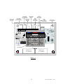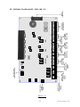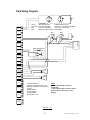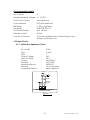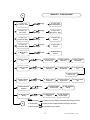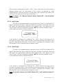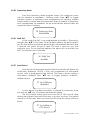
1
RE – 25AR
Agent Release Control Panel
(Protective premises Unit)
Installation, Commissioning & Operating
User Manual
Fire Alarm System Limitations
An automatic fire alarm system–typically made up of smoke detectors, heat
detectors, manual Call Points, audible warning devices, and a fire alarm control
with remote notification capability–can provide early warning of a developing fire.
Such a system, however, does not assure protection against property damage or
loss of life resulting from a fire. The Manufacturer recommends that smoke and/or
heat detectors be located throughout a protected premise following the
recommendations of the current edition of the National Fire Protection Association
Standard 72 (NFPA 72), manufacturer's recommendations, State and local codes,
and the recommendations contained in the Guide for Proper Use of System Smoke
Detectors, which is made available at no charge to all installing dealers. A study by
the Federal Emergency Management Agency (an agency of the United States
government) indicated that smoke detectors may not go off in as many as 35% of
all fires. While fire alarm systems are designed to provide early warning against fire,
they do not guarantee warning or protection against fire. A fire alarm system may
not provide timely or adequate warning, or simply may not
function, for a variety of reasons:
Smoke detectors may not sense fire where smoke cannot
reach the detectors such as in chimneys, in or behind walls, on roofs, or on the
other side of closed doors. Smoke detectors also may not sense a fire on another
level or floor of a building. A second-floor detector, for example, may not sense a
first-floor or basement fire.
Particles of combustion or "smoke" from a developing fire
may not reach the sensing chambers of smoke detectors because:
• Barriers such as closed or partially closed doors, walls,
or chimneys may inhibit particle or smoke flow.
• Smoke particles may become "cold," stratify, and not
reach the ceiling or upper walls where detectors are
located.
• Smoke particles may be blown away from detectors by
air outlets.
• Smoke particles may be drawn into air returns before
reaching the detector.
The amount of "smoke" present may be insufficient to alarm smoke detectors.
Smoke detectors are designed to alarm at various levels of smoke density. If such
density levels are not created by a developing fire at the location of detectors, the
detectors will not go into alarm.
Smoke detectors, even when working properly, have sensing limitations. Detectors
that have photoelectronic sensing chambers tend to detect smoldering fires better
than flaming fires, which have little visible smoke. Detectors that have ionizing-type
sensing chambers tend to detect fast-flaming fires better than smoldering fires.
Because fires develop in different ways and are often unpredictable in their growth,
1
RE / UM / 25AR V 1.0- 00
neither type of detector is necessarily best and a given type of detector may not
provide adequate warning of a fire.
Smoke detectors cannot be expected to provide adequate warning of fires
caused by arson, children playing with matches (especially in bedrooms), smoking
in bed, and violent explosions (caused by escaping gas, improper storage of
flammable materials, etc.).
While a fire alarm system may lower insurance rates, it is not a substitute
for fire insurance!
Heat detectors do not sense particles of combustion and alarm only when heat on
their sensors increases at a predetermined rate or reaches a predetermined level.
Rate-of-rise heat detectors may be subject to reduced sensitivity over time. For this
reason, the rate-of-rise feature of each detector should be tested at least once per
year by a qualified fire protection specialist. Heat detectors are designed to
protect property, not life.
IMPORTANT! Smoke detectors must be installed in the same room as the control
panel and in rooms used by the system for the connection of alarm transmission
wiring, communications, signaling, and/or power. If detectors are not so located, a
developing fire may damage the alarm system, crippling its ability to report a fire.
Audible warning devices such as bells may not alert people if these devices are
located on the other side of closed or partly open doors or are located on another
floor of a building. Any warning device may fail to alert people with a disability or
those who have recently consumed drugs, alcohol or medication.
Please note that:
• Strobes can, under certain circumstances, cause seizures in people with
conditions such as epilepsy.
• Studies have shown that certain people, even when they hear a fire alarm signal,
do not respond or comprehend the meaning of the signal. It is the property owner's
responsibility to conduct fire drills and other training exercise to make people
aware of fire alarm signals and instruct them on the proper reaction to alarm
signals.
• In rare instances, the sounding of a warning device can cause temporary or
permanent hearing loss.
A fire alarm system will not operate without any electrical
power. If AC power fails, the system will operate from standby batteries only for a
specified time and only if the batteries have been properly maintained and
replaced regularly.
Equipment used in the system may not be technically compatible with the control.
It is essential to use only equipment listed for service with your control panel.
2
RE / UM / 25AR V 1.0- 00
The most common cause of fire alarm malfunction is inadequate maintenance. To
keep the entire fire alarm system in excellent working order, ongoing maintenance
is required per the manufacturer's recommendations, and UL and NFPA standards.
At a minimum, the requirements of NFPA 72 shall be followed. Environments with
large amounts of dust, dirt or high air velocity require more frequent maintenance.
A maintenance agreement should be arranged through the local manufacturer's
representative. Maintenance should be scheduled monthly or as required by
National and/or local fire codes and should be performed by authorized
professional fire alarm installers only. Adequate written records of all inspections
should be kept.
NFPA Standards
This control panel complies with the following NFPA standards:
• NFPA 12 - CO2 Extinguishing Systems (High Pressure Only)
• NFPA 12A - Halon 1301 Extinguishing Systems
• NFPA 72 - Local Fire Alarm Systems (Automatic, Manual, Waterflow and Sprinkler Supervisory)
• NFPA 2001 - Clean Agent Fire Extinguishing Systems
Underwriters Laboratories Documents
• UL 38 - Manually Actuated Signaling Boxes
• UL 217 - Smoke Detectors, Single and Multiple Station
• UL 228 - Door Closers - Holders for Fire Alarm Systems
• UL 268 - Smoke Detectors for Fire Alarm Systems
• UL 268A - Smoke Detectors for Duct Applications
• UL 346 - Waterflow Indicators for Fire Protective Signaling Systems
• UL 464 - Audible Signaling Appliances
• UL 521 - Heat Detectors for Fire Protective Signaling Systems
• UL 864 - Standard for Control Units for Fire Alarm Systems
• UL 1481 - Power Supplies for Fire Protective Signaling Systems
• UL 1638 - Visual Signaling Appliances
• UL 1971 - Signaling Devices for the Hearing Impaired
3
RE / UM / 25AR V 1.0- 00
NOTES:
4
RE / UM / 25AR V 1.0- 00
Table of Contents
CHAPTER 1: Introduction ………….......................……......................8
1.1: System Design & Planning..........................................................8
1.2: General .………............................................................................8
1.3: Fire Alarm Procedure …..............................................................8
1.4: User Responsibility…....................................................................9
1.5: Routine test............…....................................……………………..9
CHAPTER 2: Product Description ...........................……...................10
2.1: Product Features ........................................................................11
2.2: Specifications .....................................................................…….13
2.3: Controls and Indicators .............................................................15
2.3.1: Controls …………………………………………………………….15
2.3.2: Indication ……………………………………………………..…...16
2.3.2.1 LED Indication……………………………………………………16
2.3.2.2.: LCD Indication …………………………………………………17
2.3.2.3: Local Buzzer …………………………………………………......17
2.4: Mechanical Construction……………………………………..…...17
2.5: Internal Arrangement…………………………….…………………18
2.6: Components……………………………………………...................19
CHAPTER 3: Installation .............................................……..........……21
3.1: Installation Precaution………………………….…………..………21
3.2: Mounting Details ..................................................…………..……22
3.3: Panel Wiring…………………………………………….……………..23
3.4: Initiating Device Circuits............................................……………28
3.5: Output Circuits .....................................................................…….29
3.5.1: Notification Appliance Circuit …………………………………..29
3.5.1: Releasing Appliance Circuit ……………………………………..30
3.5.2: 24V D.C Power ………………..……………………………………30
3.6: Standard Relay Output ……………………………………….........31
CHAPTER 4: Programming Instructions ………………………………...32
4.1: Menu Key Flow Diagram …………………………………………....32
4.2: Programming……………………………..........................................35
4.2.1.
Set Zone Mode …………………………………………………36
4.2.2.
Suppressed Supervisory ………...…………………... ……….37
4.2.3.
Suppressed Fault Events ………..…………………………….38
4.2.4.
Fire & Release Events …………………………………………..38
4.2.5.
Fault Events …….……………………………………………......38
4.2.6.
RAC 1 Mode …………………………………………………….39
4.2.7.
RAC 2 Mode …………………………………………………….39
4.2.8.
Pre Release ………………………………………………………39
4.2.9.
RAC Off Time ……………………………………………………39
4.2.10. Remote Release ………………………………………………..40
4.2.11. Input 1 Type………………………………………………………40
5
RE / UM / 25AR V 1.0- 00
4.2.12.
4.2.13.
4.2.14.
4.2.15.
4.2.16.
4.2.17.
4.2.18.
4.2.19.
4.2.20.
4.2.21.
4.2.22.
4.2.23.
4.2.24.
4.2.25.
4.2.26.
4.2.27.
4.2.28.
4.2.29.
4.2.30.
4.2.31.
4.2.32.
4.2.33.
4.2.34.
4.2.35.
4.2.36.
4.2.37.
Input 2 Type…………………………………………………….40
Input 3 Type…………………………………………………….41
Input 4 Type…………………………………………………….41
Mode Select …………………………………………………..42
Relay 1 Output ………………………………………………..42
Relay 2 Output ………………………………………………..42
Relay 3 Output ………………………………………………..42
NAC O/P Alarm ……………………………………………….43
NAC O/P Pre Release ………………………………………..43
NAC O/P Released …………………………………………..43
NAC 1 Output ………………………………………………….44
NAC 2 Output ………………………………………………….44
Zone Wiring ……………………………………………………..44
Supervisory Mode ……………………………………………...45
Walk Test …………………………………………………………45
Auto Silence …………………………………………................45
Silence Inhibit ………………………………………………......46
AC Loss Delay …………………………………………………..46
Trouble Remainder ……………………………………………46
24V Output ……………………………………………………..47
Set Date …………………………………………………………47
Set Time ………………………………………………………….47
Change User Password ……………………………………….48
Change Admin Password …………………………………….48
Restore Default Settings ……………………………………….49
About ……………………………………………………………..49
CHAPTER 5: Operating Instructions......................................................50
5.1: Switch Functions ……………………...............................................50
5.2: Indications ....................................….........................………………51
5.3: Operation..................................................................………………53
5.3.1: Normal Monitoring Mode………………………………………….53
5.3.2: Fire Alarm Condition.............................................….. ………….53
5.3.3: Supervisory …………………………………………………………..54
5.3.4: Fault………………………….………………………………………..55
5.3.5. Disable / W.T…………………………………………………………56
5.3.6: Manual Abort ……………………………………………………….57
5.3.7: Manual Release ……………………………………………………57
5.3.8: Pressure Switch ……………………………………………………..57
5.3.9: Alarm Verification ………………………………………………….58
5.3.10: Gas Release ……………………………………………………….59
CHAPTER 6: Servicing……………………………..……………………….60
6.1: Installation / Replacement of PCB……………………..………….60
6.2: Lamp Test…………………………………………………...................62
6.3: Walk test…………………………………………………………………62
6.4: System Power / Size …………………………………..……………….63
6
RE / UM / 25AR V 1.0- 00
6.5: Trouble Shooting ………………………………………………………63
CHAPTER 7: Battery Calculation ………..….……….………….………..64
CHAPTER 8: wire Requirement………………..…………………………..65
CHAPTER 9: Compatible Devices ……….………….……………………66
CHAPTER 10: Abbreviation …………………………………………………67
7
RE / UM / 25AR V 1.0- 00
Chapter 1:
Introduction
The RE – 25AR Agent Release Control Panel performs the functions of fire
suppression in a wide variety of applications. The panel has capable to use in an
agent release sprinkler system. It can be used as single – hazard or dual – hazard
application with or without cross-zoning.
This manual is intended as a complete guide to the Agent Release Control
Panels. This manual provides complete information on installation, commissioning,
Operating Instructions, programming guide, service, and maintenance procedures
with full technical details.
1.1 System Design and Planning
It is assumed that the system, of which this control panel is a part, has been
designed by a competent fire alarm system designer in accordance with the
requirements of NFPA – 72 and any other local codes of practice that are
applicable. The design drawings should clearly show the positions of the field
devices and the control equipment.
1.2 General
The panel is self-contained with integral power supply and space provision
for two sealed lead-acid standby batteries and complies with the requirements of
NFPA – 72. The panel’s functions are microprocessor controlled and test and
disable functions are included. The panel can accept, per zone, automatic
detectors with a total maximum loading of 2mA quiescent current rating (refer to
chapter 2.2), and an unlimited number of manual call points. The panel includes
common alarm, supervisory, and trouble relays, and provides regulated and
unregulated auxiliary power along with four-wire smoke power. It supports auxiliary
relays and a city tie module. The auxiliary relays are based on a hazard area status.
The RE – 25AR has six input zones and four output zones, allowing for flexibility in
most single and dual hazard application for agent releasing applications.
Installation
The panel is easy to install and operate. Control functions Programming functions
are enabled by using password. The panel fascia is retained by tamper-proof
screws.
1.3 Fire Alarm Procedures
In accordance with NFPA – 72, written procedures should be laid down for dealing
with alarms of fire, fault warnings, and the isolation of any part of the system. The
responsible person should ensure that users of the system are instructed in its proper
use and are familiar with the procedures.
8
RE / UM / 25AR V 1.0- 00
On hearing the fire alarm:
CARRY OUT THE PRESCRIBED PROCEDURE Subsequent actions will depend on the
circumstances, and may include silencing the audible alarms and resetting the
system, as described later.
To Evacuate the premises:
Press the Evacuate key and enter the password to OPERATE NAC’s (Sounders).
Fault Indication:
If the control panel indicates a Fault condition, make a note of all illuminated
indicators and proceed as described in chapter 6 (Section 6.5) or call service
engineer.
1.4 User Responsibility
In addition to the routine testing described on routine test, the user has a
responsibility for ensuring certain actions are taken following a fire or fault, and for
implementing remedial action following a specified incidence of false alarms. As a
minimum, the user shall record any incident and inform the service organization,
who may be required to retest the system.
1.5 Routine Testing
In order to ensure that the system is fully operational, and to comply with the
requirements of UL864 Standard & NFPA – 72, the following routine attention is
recommended:
Daily - Check the panel to ascertain that it indicates normal operation. If any fault is
indicated check that it has been recorded and the appropriate actions have been
taken e.g. informing to the maintaining company.
Weekly - Test at least one detector or call point to confirm the operation of the
panel and the audible alarms. Test a different zone each week and, if possible, a
different device. Keep a record of the device and zone tested each week. Record
and report any malfunction.
Quarterly - The responsible person should ensure that every three months the system
is checked by a competent person. Check the standby batteries and the charger
voltage Test at least one device in each zone to check the panel functions. Check
the operation of the audible alarms and any link to a remote manned centre,
Central Station, etc. Carry out a visual inspection of the installation to check for
alterations or obstructions and issue a certificate of testing.
Annually - The responsible person should ensure that, in addition to the quarterly
checks, each device on the system is tested and that a visual inspection is made of
the cable fittings and equipment.
Note: The control panel cabinet should be cleaned periodically by wiping with a
soft, damp cloth. Do not use any solvents.
9
RE / UM / 25AR V 1.0- 00
Chapter 2:
Product Description
The RE – 25AR Agent Release Control Panel performs the functions of fire
suppression in a wide variety of applications. It can be used as single – hazard or
dual – hazard application with or without cross-zoning. The panel includes common
alarm, supervisory, and trouble relays, and provides unregulated auxiliary power
along with four-wire smoke power. The auxiliary relays are based on a hazard area
status. The RE – 25AR has eight inputs and four outputs, allowing for flexibility in most
single and dual hazard application for agent releasing applications.
10
RE / UM / 25AR V 1.0- 00
2.1
Product Feature
4 Class B initiating device circuit (IDC).
All zones accept smoke detectors and any normally open contact
device.
Any Zone can be configured as Alarm or supervisory Zone.
2 Class B Releasing Agent Circuits (RAC).
2 Class B Notification Appliance Circuits (NAC).
Fully complies with UL -864 9th Edition and NFPA-72.
Rugged CRCA sheet with powder coated finish.
Operates on 120 - 220v 60 / 50 Hz, AC Mains power supply.
Standby (battery) backup 24v DC power supply with built in charger
16x2 Dot Matrix LCD Display.
Error free Fire / Fault status in unambiguous colored LED indication.
System ON indication.
Main, Standby status audible and visual indication.
Battery Low visual warning with audible tone.
3 Form–C programmable relays for fault / supervisory / Fire / Cross Zone / Gas
Release.
Programmable 24v D.C. Outputs.
Programmable Mode (Auto/Manual) Selection
Programmable RACs.
Lamp Test facility.
Walk Test facility.
Zone Isolation facility with loop voltage cut off.
Earth fault annunciation facility at 0 ohms.
All field wiring circuits are Power limited except 120 / 220v AC and Battery.
All field wiring circuits are supervised.
AC Low voltage cutoff.
Programmable NAC’s.
Programmable IDC’s.
Programmable Supervisory Mode.
Programmable AC loss delay.
Alarm verification facility.
Programmable Trouble reminder facility.
11
RE / UM / 25AR V 1.0- 00
Power Limited
Programmable
Inputs 1 & 2and RAC1
Power Limited
Programmable
Inputs 3 & 4 and RAC 2
ZONE - 4
_
+
ZONE - 3
_
+
ZONE - 2
_
+
ZONE - 1
_
+
CN 11
Relay 3
NC NO C
Non-supervised
Power Limited
Power Limited
Resettable
24V DC O/P
INPUT - 4
INPUT - 3
RAC - 2
INPUT - 2
INPUT - 1
RAC - 1
OU T
OU T
_
OU T
OU T
_
IN
CNA 12
IN
+
CN 14
IN
IN
CN 12
+
CN 13
24V-SEN
OU T
IN
CN 9
24 V O /P
_
+
CN 10
NAC - 2
NAC - 1
_
_
+
CN 8
+
CN 7
FIRE RELAY
NC
CN 5
NO
C
PRO G-RLY2
NC
NO
C
CN 4
Relay 1
NC NO C
Non-supervised
Power Limited
Primary Source
120/ 220 AC 60/50 Hz
PRO G-RLY1
NC
NO
C
CN 6
F3
F7
Q8
F6
Q9
F5
Q10
F4
DC INPUT
Power Limited
Zone Terminals
Zone 1 to 4
Relay 2
NC NO C
Non-supervised
Power Limited
Power Limited
24V NAC 1 &2
Output
Q 12
CN 1
U7
U6
U8
U9
CN 3
Q1
24 V BAT I N
F1
Fuse1
CN 2
26 Pin FRC
Front Sticker
Standby Source
12V 12Ah Battery
Standby Source
12V 12Ah Battery
Figure – 1
12
RE / UM / 25AR V 1.0- 00
2.2
Specification
Primary Power (RE-SMPS-4A-R1)
120 - 220VAC + 10% -15%, 60 / 50 Hz, 2.5Amps.
Standby Power
24v D.C (2 Nos of 12v, 12Ah Sealed Lead acid battery).
Operating Condition
Operating Temperature – 0 - 49° C / 32 - 120° F.
Relative Humidity – 93 ± 2% RH (non-condensing) at 32 ±2° C/95 ±3°F.
Charging Circuit
Charging Voltage – 28V, ±0.5V
Charging Current – 800mA (Max.).
Initiating Device Circuits - CN11
All zones are Class B Style B/C operation (Programmable).
Normal Operating Voltage: 14 - 21 VDC.
Alarm Current: 15 – 30mA.
Short Circuit Current: 45mA Maximum.
Loop resistance: 100 ohms Maximum.
End-Of-Line Resistor: 3K9, 1/2watt
Standby Current: 7mA (2mA for Detectors)
Note: For compatible devices refer Chapter 9(CD 01).
Notification Appliance Circuits – CN 7 & 8
Class – B Style - Y wiring
Operating Nominal Voltage: 24VDC – Special Application
Current for all NACs: 1.2Amps (0.6A per circuit)
Current Limit: via Thermal Fuse
Line Drop: 1.8V
End-Of-Line Resistor: 3K9, 1/2watt
Note: For compatible devices refer Chapter 9(CD 01).
Releasing Appliance Circuits – CN 13 & 14
Class – B Style - Y wiring
13
RE / UM / 25AR V 1.0- 00
Operating Nominal Voltage: 24VDC – Special Application
Current for all RACs: 1.2Amps (0.6A per circuit)
Current Limit: via Thermal Fuse
Line Drop: 1.8V
End-Of-Line Resistor: 3K9, 1/2watt
D.C. Power – CN10
Operating Voltage: Supervised 24VDC regulated, 300mA Max. (for 4 wire smoke
detector)
Common Three Form – C Relays – CN4, CN5, CN6
Relay Contact Rating: 2Amps @ 30 VDC, 2Amps @ 30VAC.
Power Factor: 0.6
Programmable Input circuits
No. of Inputs: 4
Normal Operating Voltage: 8 - 12 VDC.
Short Circuit Current: 5mA Maximum.
Loop resistance: 100 ohms Maximum.
End-Of-Line Resistor: 3K9, 1/2watt
Standby Current: 2.5mA
Total No. of Devices: 3 (for Manual Release & Actuator
Pressure Low) during combination only.
14
RE / UM / 25AR V 1.0- 00
2.3
Control and Indication
Figure – 2
2.3.1.
Controls:
ACK. Key:
To mute local buzzer in alarm condition.
To mute local buzzer in Supervisory or fault condition.
User or Admin password protected.
SILENCE Key:
To silence the external NACs in Fire Condition.
User or Admin password protected.
RESET Key:
To reset the particular zones in Fire alarm or Latched Supervisory condition.
User or Admin password protected.
Possible to access only after silence in alarm condition.
DRILL:
To activate External NACs Manually.
User or Admin password protected.
15
RE / UM / 25AR V 1.0- 00
CURSOR KEYS:
To move the cursor point in the LCD as required and increase and decrease
the values.
ENTER Key:
To accept the programmed or edited menu, mode or value in the LCD.
MENU Key:
To enter into the Main Menu in the LCD.
ESC:
To go back to the previous screen or erase the password entered.
2.3.2.
2.3.2.1
Indications:
LED indication
System On – Green
Fire – Red
Fault – Yellow
Supervisory – Yellow
Mains Fail – Yellow
Battery Fail – Yellow
Earth Fault – Yellow
System Fault – Yellow
Disable – Yellow
DC O/P Fault – Yellow
Manual Mode – Yellow
Silenced – Yellow
NAC Fault – Yellow
Walk Test – Yellow
RAC Fault – Yellow
Pre Release – Green
Pressure Low – Yellow
Man. Release – Red
Abort – Yellow
Released – Red
16
RE / UM / 25AR V 1.0- 00
Zone Fire – Red
Zone Supervisory – Yellow
Zone Fault – Yellow
2.3.2.2
LCD Indication
The LCD is mainly used for the programming of the panel. It also indicates all
events along with the LED indications except system on and system fault.
2.3.2.3
Local Buzzer
A piezo buzzer provides separate and distinct sounds for alarm, trouble and
supervisory conditions:
2.4
Alarm – Continuous
Fault – pulse 0.5sec ON and 5sec OFF
Supervisory – pulse 0.25sec ON and 0.25sec OFF
Mechanical Construction
The enclosure of the Panel is constructed by 18 gauge (1.22mm) CRCA sheet
with powder-coated finish. The ∅22.25mm (∅19mm [11No’s] for Indian Std.) 10no’s
of knockouts are given for cable entry at the top of the cabinet. The lockable
hinged door is provided to access the inside the cabinet. The panel also has
sufficient space to accommodate 2 Nos. of 12v, 12Ah batteries.
350 MM
120 MM
440 MM
Figure – 3
17
RE / UM / 25AR V 1.0- 00
Top View
mm 10 No’s
mm 10No’s
120mm
350mm
7mm
18mm
LHS View
Front View
RHS View
440 mm
Botton View
Figure – 4
2.5
Internal Arrangement
Non Power Limited
Cable Entry
Wire Size = ‘X’ AWG
CON 2
ontrol
y&C
Displa oard
B
25A
L-RE(RAVE
CON 2
Master Board
Power Supply
Board
(RAVEL-RE-25AR-MB-R1)
(RAVEL-RE-SMPS-4A-R1)
-R1)
R-DISP
12v 12Ah
Sealed Lead Acid Battery
12v 12Ah
Sealed Lead Acid Battery
Figure – 5
18
RE / UM / 25AR V 1.0- 00
Components
Master Board (RE – 25AR – MB – R1)
225 mm
ZONE - 4
_
+
ZONE - 3
_
+
ZONE - 2
_
+
ZONE - 1
_
+
CN 11
INPUT - 4
INPUT - 3
RAC - 2
INPUT - 2
INPUT - 1
RAC - 1
OUT
OUT
_
OUT
OUT
_
IN
CNA 12
IN
+
CN 14
IN
IN
CN 12
24V-SEN
OUT
+
CN 13
24V O/P
_
IN
CN 9
+
CN 10
NAC - 2
NAC - 1
_
_
+
CN 8
+
CN 7
RELAY 3
NC
CN 5
NO
RELAY - 2
C
NC
NO
RELAY - 1
C
CN 4
NC
NO
C
CN 6
F3
F5
Q9
Q10
F4
Q12
CN 1
136 mm
Q8
F6
DC INPUT
F7
125 mm
U7
U6
U9
U8
CN 3
Q1
24V BAT IN
F1
Fuse1
CN 2
236 mm
Figure – 6
The Zone board contains the primary components and wiring interface
connectors.
Display Board (RE – 25AR – DISP-R1)
The Display Board contains the system CPU, LED Display, LCD unit and
146 mm
Control keys.
73 mm
162 mm
2.6
Figure – 7
19
RE / UM / 25AR V 1.0- 00
Power Supply (RE – SMPS – 4A – R1)
Figure – 8
This Power supply gives the 30V DC output for the Zone Board. This
board is SMPS type, it gives the output for 2.5Amps Max (4Amp During Initial
condition).
Cabinet
The Cabinet measures 440mm width X 340mm Height X 120mm Depth
and space is provided for 2 x 12 Volt 12Ah Batteries, main circuit board and
display board.
20
RE / UM / 25AR V 1.0- 00
Chapter 3: Installation
3.1 Installation Precaution
Installation Precautions
WARNING - Several different sources of power can be
connected to the fire alarm control panel. Disconnect all
sources of power before servicing. Control unit and
associated equipment may be damaged by removing
and/or inserting cards, modules, or interconnecting cables
while the unit is energized. Do not attempt to install, service,
or operate this unit until this manual is read and understood.
CAUTION - System Reacceptance Test after Software
Changes. To ensure proper system operation, this product
must be tested in accordance with NFPA 72 after any
programming operation or change in site-specific software.
Reacceptance testing is required after any change,
addition or deletion of system components, or after any
modification, repair or adjustment to system hardware or
wiring.
All components, circuits, system operations, or
software functions known to be affected by a change must
be 100% tested. In addition, to ensure that other operations
are not inadvertently affected, at least 10% of initiating
devices that are not directly affected by the change, up to
a maximum of 50 devices, must also be tested and proper
system operation verified.
This system meets NFPA requirements for indoor dry
operation at 0-49° C/32-120° F and at a relative humidity of
93 ±2% RH (non-condensing) at 32 ±2° C/95 ±3° F. However,
the useful life of the system's standby batteries and the
electronic components may be adversely affected by
extreme temperature ranges and humidity. Therefore, it is
recommended that this system and all peripherals be
installed in an environment with a nominal room
temperature of 15-32° C/60-95° F.
Verify that wire sizes are adequate for all IDC’s loops. Most devices cannot tolerate
more than a 10% I.R. drop from the specified device voltage.
Adherence to the following will aid in problem-free
installation with long-term reliability:
Like all solid-state electronic devices, this system may
operate erratically or can be damaged when subjected to lightning-induced
transients. Although no system is completely immune from lightning transients and
interferences, proper grounding will reduce susceptibility. Overhead or outside
aerial wiring is not recommended, due to an increased susceptibility to nearby
lightning strikes. Consult with the Technical Services Department if any problems are
anticipated or encountered.
21
RE / UM / 25AR V 1.0- 00
Disconnect AC power and batteries prior to removing or inserting circuit boards.
Failure to do so can damage circuits.
Remove all electronic assemblies prior to any drilling, filing, reaming, or punching of
the enclosure. When possible, make all cable entries from the sides or rear. Before
making modifications, verify that they will not interfere with battery, transformer,
and printed circuit board location.
Do not tighten screw terminals more than 1.0168 N-m.
Over-tightening may damage threads, resulting in reduced terminal contact
pressure and difficulty with screw terminal removal.
Though designed to last many years, system components
can fail at any time. This system contains static-sensitive
components. Always ground yourself with a proper wrist strap before handling any
circuits so that static charges are removed from the body. Use static-suppressive
packaging to protect electronic assemblies removed from the unit.
Follow the instructions in the installation, operating, and programming manuals.
These instructions must be followed to avoid damage to the control panel and
associated equipment. FACP operation and reliability depend upon proper
installation by authorized personnel.
3.2
Mounting Details
30 mm
284 mm
36 mm
30 mm
380 mm
30mm
Figure – 9
22
RE / UM / 25AR V 1.0- 00
Remove all the Boards before placing the panel in its mounting position.
Place the panel in its mounting position and fix the panel to the wall using the slots
of the four screws. Ensure the enclosure and the inner parts of the panel are given
sufficient protection during installation. Fix the all boards in its position (Refer
Figure25, 26 & 27). All external cables are to be entered via the 20 numbers of
preformed knockouts located at top of the panel.
When the installation of all the cables has been completed, clean the interior of
the enclosure ensuring all masonry debris and drilling swords are removed.
3.3
Panel Wiring
Warning: Several different sources of power can be connected to this panel.
Disconnect all sources of power before servicing. The panel and associated
equipment may be damaged by removing and / or inserting cards, modules or
inter connecting while this unit is energized.
Primary Power source (AC) and Earth Ground Connections
AC Power connections are made inside the control panel cabinet. The Primary
source for the RE - 25AR is 120 - 220 VAC, 60 / 50 Hz, 2.5 Amps. Run a pair of wires
with Earth conductor from the protected premises main breaker box to
connector CON1 (RE – SMPS – 4A – R1) of the power supply board. As per
National Electrical Code, use 14 AWG (2.00 mm2, 1.6mm O.D) or heavier gauge
wire with 600V insulation. No other equipment may be connected to this circuit.
In addition, this circuit must be provided with over current protection and may
not contain any power disconnect devices. A separate Earth Ground
connection must be made to ensure the proper panel operation and lighting
and transient protection. Connect the Earth Ground wire (Min. 14AWG / 2.00
mm2) to the connector CON1.
Standby Power Source (Batteries)
Observe polarity when connecting the battery. Connect the battery cable to
connector CN2 on the Zone board (RE – 25AR – MB – R1) using the connector
and cable provided. The battery charger is current – limited and capable of
recharging sealed lead acid type batteries upto 12Ah.
During alarm condition, the charger section is disconnected from the battery
hence there will not be any charging at that time.
23
RE / UM / 25AR V 1.0- 00
RE – 25AR Power Supply Circuit Board (RE – SMPS – 4A – R1)
Figure - 10
RE – 25AR Power Supply Monitor Circuit Board (RE –Monitor)
Figure – 11
24
RE / UM / 25AR V 1.0- 00
RE – 25AR Main Circuit Board (RE – 25AR – MB – R1)
26 Pin FRC to
Display
CN 3
_
_
+
ZONE - 3
_
+
ZONE - 2
Power Limited
Zone Terminals
Zone 1 to 4
+
_
+
ZONE - 1
Q8
OUT
IN
INPUT - 3
+
F7
CN 14
_
RAC - 2
IN
OUT
Q9
IN
INPUT - 1
+
F6
CN 13
_
RAC - 1
+
Q12
F3
CN 10
_
24V O/P
CN 7
_
+
NAC - 1
CN 8
F4
+
F5
_
NAC - 2
CN 5
NC
NO
C
FIRE RELAY
CN 4
NC
C
CN 2
NO
C
PROG-RLY1
NC
CN 6
CN 1
Relay 2
NC NO C
Non-supervised
Power Limited
24V BAT IN
NO
PROG-RLY2
Relay 3
NC NO C
Power Limited
Non-supervised
Resettable
Power Limited
24V DC O/P
Power Limited
24V NAC 1 &2
Output
IN
Q10
CN 9
OUT
24V-SEN
Power Limited
Solenoid O/P
RAC1
Power Limited
Programmable
Inputs 1 & 2
CN 12
OUT
INPUT - 2
Power Limited
Solenoid O/P
RAC2
Power Limited
Programmable
Inputs 3 & 4
IN
INPUT - 4
OUT
CNA 12
U7
U9
Fuse1
Relay 1
NC NO C
Non-supervised
Power Limited
30V DC
Input from
SMPS
(Power Limited)
RE / UM / 25AR V 1.0- 00
25
ZONE - 4
CN 11
U6
U8
Q1
F1
24V DC Standby Input
(Power Limited)
DC INPUT
Figure – 12
Field Wiring Diagram
D1
_
Zone 4
D1,D2
Bd1, Bd2
EOL
NAC
- Two wire detectors
- Four wire detectors.
- End Of Line Resistor
- Notification Alarm Circuit
_
+
Zone 3
Bd1
D2
EOL
Initiating Device Circuit
IDC’s are 1 to 8, Class B StyleB/C
End of Line - 3K9 1/2W
PN: RE3K9
Bd2
_
+
Zone 2
EOL
_
+
Zone 1
_
_
+
IN
Input 3
OUT
_
+
+
RAC - 2
(0.6A)
RE-Monitor
+
+
Input 4
VALVE
_
Input 2
_
+
Input 1
_
+
+
RAC - 1
(0.6A)
RS
Sense
OUT
RS 24V
Output
(300mA)
_
NAC - 2
(0.6A)
_
+
EOL
_
+
EOL
NAC
NAC
+
NAC - 1
(0.6A)
IN
NC
Relay 3
NO
NC
Relay 2
NO
NC
Relay 1
NO
120 - 220V
AC Input
N
3 Potential Relays
For Fire, Fault, Supervisory, Pre
Release, Released - Power Limited
outputs.
Contact Rating:
2.0A @ 30VDC
2.0A @ 30VAC
Power Factor: 0.6
Note:
All the field wiring circuits are
supervised.
All the field wiring circuits are Power
limited except 120-220v A.C and
Battery.
P
Figure – 13
26
RE / UM / 25AR V 1.0- 00
73 mm
15 mm
110 mm
105 mm
15 mm
22.23 mm
60 mm
Mounting OF RE - Monitor
19 mm
15 mm
60 mm
15 mm
90 mm
Figure - 14
PCB
PCB
Mounting
Hole
Figure – 15
27
RE / UM / 25AR V 1.0- 00
3.4 Initiating Device Circuit
No. of Initiating circuit
:
4 Zone
Type
:
Class B
Style
:
B / C Programmable
Wire Size
:
1.5 sq. mm Max.
Operating Voltage
:
14 - 21 VDC Nominal (Max.)
Terminal
:
CN11
Loop Resistance
:
100 Ω Max.
Total No. of Devices
:
16
Monitoring Device
Compatible Devices
:
:
3K9 (EOL) (Refer Chapter 9)
Refer Chapter 9.
All zones may be configured for general fire alarm applications or supervisory
alarm zones.
Four-wire smoke detectors may be connected to any zone. Resettable
power is provided via CN10.
Note:
a. Only smoke detectors can be connected in the zone with alarm
verification
b. Only Same model detectors should be used in IDC.
c. Manual Pull Station should not be used in the style ‘C’ mode.
Warning: This unit includes an Alarm Verification Feature that will result in a
delay of the system alarm signal from the indicated circuits. The total delay
shall not exceed 80 Sec. no other smoke detector shall be connected to
these circuits unless approved by the local authority having jurisdiction.
E.O.L. RESISTOR 3K9 OHMS
E.O.L. RESISTOR 3K9 OHMS
SMOKE DETECTOR
SMOKE DETECTOR
HEAT DETECTOR
HEAT DETECTOR
Manual Call Point
Manual Call Point
E.O.L. RESISTOR 3K9 OHMS
FOR UNUSED ZONE LOOPS
Z4
Z3
Z2
Z1
Figure – 16
28
RE / UM / 25AR V 1.0- 00
Programmable Inputs:
No. of Inputs
:4
Normal Operating Voltage : 8 - 12 VDC.
Short Circuit Current
: 5mA Maximum.
Loop resistance
: 100 ohms Maximum.
Wire Size
Terminal
: 1.5 sq. mm Max.
: CN12 & CN 16
End-Of-Line Resistor
: 3K9, 1/2watt
Standby Current
: 2.5mA
Total No. of Devices
: 3 (for Manual Release & Actuator Pressure Low)
during combination only
3.5 Output Circuits
3.5.1 Notification Appliance Circuits
No. of NAC
Type
Style
Output Voltage
Max. Line Drop
Current
Terminals
Monitoring Device
Wire Size
Compatible Device
:
:
:
:
:
:
:
:
:
:
2 Ckts.
Class B
Y
24 V
1.8 V
0.6A (Each)
CN7, CN8
3K9 (EOL)
1.5 sq. mm Max.
Refer Chapter 9.
EOL
+
+
Non Polarized
Sounder
+
Polarized
Sounder
NAC 2 NAC 1
Retain E.O.L Resistor 3K9 Ohms
for unused circuits
Figure – 17
29
RE / UM / 25AR V 1.0- 00
3.5.2 Releasing Appliance Circuits
No. of RAC
:
Type
:
Style
:
Output Voltage :
Max. Line Drop
:
Current
:
Terminals
:
Monitoring Device :
Wire Size
:
2 Ckts.
Class B
Y
24 V
1.8 V
0.6A (Each)
CN13, CN14
3K9 (EOL)
1.5 sq. mm Max.
EOL
Non Polarized
Valve
NAC 2 NAC 1
Retain E.O.L Resistor 3K9 Ohms
for unused circuits
3.5.3 24V D.C Power (300mA)
Output Voltage
Current
Output Terminal
Wire Size
Monitoring Device
Monitoring Terminal
CN9 Link
:
:
:
:
:
:
:
24 VDC Nominal
0.3A Max.
CN10
1.5 sq. mm Max
RE – MONITOR (Refer Chapter 9)
CN9
3K9 Max. (Refer Chapter 9)
NOTE:
The Link should be disconnected after connecting monitoring device.
RE - Monitor
24V DC
Sense
RS 24V
I/P
IN
-
+
OUT IN
-
+
OUT
CN12
CN 7
RS - SEN
RS 24V
OP
Fire Alarm Panel
Figure – 18 (Resettable O/P)
30
RE / UM / 25AR V 1.0- 00
3.6 Standard Relay Output Circuits
No. of Programmable Relay Output
zone, Gas Release)
:
3 (Fire, Fault, Supervisory, cross
Contact Voltage
:
30 VDC Nominal
Current Rating
:
2A
Type of Relay
:
Form – C
Relay 3 Relay 2 Relay 1
Relay 3 Relay 2 Relay 1
Relay contacts shown with power applied to
the panel no active Fire or Gas Release
If the relay is configured as fault, then it will reverse
Relay contacts shown with power applied to
the panel active Fire or Gas Release
If the relay is configured as fault, then it will reverse
Figure – 19
Figure – 20
31
RE / UM / 25AR V 1.0- 00
CHAPTER 4: Programming Instructions
Notice to USERS, INSTALLERS. AUTHORITIES HAVING JURISDICTION, AND OTHER INVOLVED
PARTIES
This product incorporates field-programmable software. In order for the product to
comply with the requirements in the Standard for control Units and Accessories for Fire
Alarm Systems, UL 864, certain programming features or options must be limited to
specific values or not used at all as indicated below.
Program Feature or
Option
Permitted in UL 864?
(Y/N)
Possible settings
Setting Permitted in
UL 864
NAC O/P Alarm, Pre
Release, Released
Yes
Temporal, Steady,
Synchronized, 120
BPM
Temporal, Steady,
Synchronized
4.1
Menu Key Flow Diagram:
Admin
Password
MENU KEY - FLOW DIAGRAM
Me nu
Key
1. Set Zone
Mode
1 2 3 4
F S A W
2. Suppressed
supe rvisory
Sup-Suprv [X/Y ]
Zone Z
(If any
fault)
3. Suppre ssed
Fault
Sup-Fault [X/Y]
Fault
(If any
fault)
Default Password:
User: 1234
Admin: 54321
Use Cursor Key to
view next / previous
Events
4. Fir e & Rele ase
Events
Use Enter Key to
view Events
5. Fault
Ev ents
Use Enter Key to
view Events
6. RAC1 Mode
Zone 1&2
Use
Key to
Type/Options
6. RAC1 Mode
Zone 1 / 2 / 1or2
7. RAC2 Mode
Zone 3&4
Use
Key to
Type/Options
7. RAC2 Mode
Zone 3 / 4 / 3 or 4 /
Disabled
Use Cursor Key to
view next / previous
Events
8. Pre Rele ase
20 (Secs)
Use Curso r Key to
Increase / Decrease
the ti me d el ay
Use
Key to
Type/Options
8. Timer Delay
Disabled
9. RAC Off Time
10 (Secs)
Use Curso r Key to
Increase / Decrea se
the time d el ay
Use
Key to
Type/Options
9. RAC Off Time
Disabled
10. Rmt Release
10 (Secs)
Use Cursor Key to
Increase / Decrease
the time dela y
Use
Key to
Type/Options
10. Rmt Release
Disabled
Note:
1. Use Cursor key (
A
2. Use Enter Key (
3. Use Cursor key (
) to move the menu list and to interchange the status of the menu.
) to select the menu list and conform the change of the status.
) to change the value / options.
32
RE / UM / 25AR V 1.0- 00
MENU KEY - FLOW DIAGRAM
A
11. I nput 1 Typ e
Man Release - RAC1
Use
Change
Mode/Type
Man Rel&Abrt-RAC1
12. Inp ut 2 Type
Abort - RAC1
Use
Change
Mode/Type
12. Input 2 Type
Man Release - RAC2
13. Inp ut 3 Type
Pre ssure SW - RAC1
Use
Change
Mode/Type
13. In put 3 Type
Disable d
14. I nput 4 Typ e
P ressure S W- RAC2
Use
Change
Mode/Type
14. Input 4 Type
Disabled
15. Mode Select
Auto
Use
Change
Mode/Type
15. Mode Select
M anual
16. Relay 1 Output
Fire
17. Relay 2 Output
Fault
11. Input 1 Type
Use
Change
Mode/Type
16. Relay 1 Output
Supervisory
16. Relay 1 Output
Released
16. Re lay 1 Output
Pre Release
Use
Change
Mode/Type
17. Relay 2 Output
Rele ased
17. Relay 2 Output
Pre Rele ase
17. Relay 2 Output
Fire
17. Relay 2 Output
Supervisory
18. Relay 3 Output
Supervisory
Use
Change
Mode/Type
19. NAC O/P-Alarm
Temporal
20. NAC O/P-PreRl
Steady
18. Relay 3 Output
Released
Use
Change
Mode/Type
Use
Change
Mode/Type
18. Relay 3 Output
Pre Release
19. NAC O/P-Alarm
Synchronized
20. NAC O/P-PreRl
Temporal
18. Relay 3 Output
Fire
19. NAC O/P-Alarm
Steady
20. NAC O/P-PreRl
Synchr onized
Note:
1. Use Cursor key (
B
2. Use Enter Key (
3. Use Cursor key (
) to move the menu list and to interchange the status of the menu.
) to select the menu list and conform the change of the status.
) to change the value / options.
33
RE / UM / 25AR V 1.0- 00
B
MENU KEY - FLOW DIAGRAM
21. NAC O/P-Relsd
Synchronized
Use
Change
Mode/Type
21. NAC O/P-Re lsd
Temporal
21. NAC O/P-Re lsd
Steady
22. NAC1 Output
RAC 1
Use
Change
Mode/Type
22. NAC1 Output
Common
23. NAC2 Output
RAC 2
Use
Change
Mode/Type
23. NAC2 Output
Common
24. Zone Wiring
Class-B Style-C
Use
Change
Mode/Type
24. Zone Wiring
Class-B Style-B
25. Suprvisory Mde
Use
Change
Mode/Type
25. Suprvisory Mde
Re se tta ble
26. Walk Test
Audible
Use
Change
Mode/Type
26. Walk Test
Silent
27. Auto Silence
Disabled
Use
Change
Mode/Type
27. Auto Silence
120 (Secs)
Use Cursor K ey to
Increa se / De crea se
the time del a y
28. Silence Inhbt
Disabled
Use
Change
Mode/Type
28. Silence Inhbt
060 (Secs)
Use Cursor K ey to
Increa se / De crea se
the time del a y
Latc he d
Use C ursor Key to
Increa se / Decrea se
the ti m e del a y
Use Cha nge Ke y to
M ode/Type
29. AC Loss Dly
120 (Mins)
30. Trouble Remin
720 (Mins)
Use C ursor Key to
Increa se / Decrea se
the ti m e del a y
Use Cha nge Ke y to
M ode/Type
30. Trouble Remin
Disabled
29. AC Loss Dly
31. 24v O utput
Re se tta ble
Disable d
31. 24v Output
Use
Change
Mode/Type
Ste ad y
32. Se t Da te
24/12/10
DD/MM/YY
Use Cursor
Key to
Increa se / De crea se
the Da te
33. Set Time
10:10
HH : M M (24hrs)
Use Cursor
Key to
Increa se / De crea se
the ti me
34. Change Use r
Pa ssw ord
35. Change Adm in
Passw ord
36. Restore
De fa ult Se ttin gs
37. Abort
Enter Old
Password?
Enter New
Passwor d?
Confirm New
Password?
P a ssw ord
Upda ted
Enter Old
Password?
Enter New
Passwor d?
Confirm New
Password?
P a ssw ord
Upda ted
!W arning! P re ss
ENTER To re store
Password?
Resetting...
Model: RE-25AR
Version 1.0
Note:
1. Use Cursor key (
2. Use Enter Key (
3. Use Cursor key (
) to move the menu list and to interchange the status of the menu.
) to select the menu list and conform the change of the status.
) to change the value / options.
34
RE / UM / 25AR V 1.0- 00
4.2
Programming:
The MENU key is used to enter into the programming mode for
changing and configuring the Input & Output details and other settings. To
enter into the menu, admin password is must. The various steps involved in this
menu are shown as flow chart 4.1. After entering into the menu, screen will
show the first menu as below,
1. Set Zone
Mode
To move the next menu use the left / right cursor key, and press Enter /
‘’ key to change the settings. The programmable menu list is as follows.
1.
2.
3.
4.
5.
6.
7.
8.
9.
10.
11.
12.
13.
14.
15.
16.
17.
18.
19.
20.
21.
22.
23.
24.
25.
26.
27.
28.
29.
30.
31.
32.
33.
34.
35.
36.
37.
Set Zone Mode
Suppressed Supervisory
Suppressed Faults
Fire & Release Events
Fault Events
RAC1 Mode
RAC2 Mode
Pre Release
RAC Off Time
Rmt Release
Input 1 Type
Input 2 Type
Input 3 Type
Input 4 Type
Mode Select
Relay 1 Output
Relay 2 Output
Relay 3 Output
NAC O/P Alarm
NAC O/P PreRl
NAC O/P Relsd
NAC1 Output
NAC2 Output
Zone Wiring
Supervisory Mde
Walk Test
Auto Silence
Silence Inhbt
AC Loss Dly
Trouble Remin
24V Output
Set Date
Set Time
Change User Password
Change Admin Password
Restore Default Settings
About
35
RE / UM / 25AR V 1.0- 00
4.2.1
Set Zone Mode
From the Set Zone Mode program screen, By pressing the “Enter” key
the system enters into the zone set mode. In this mode the zone mode can
be changed to fire, supervisory, alarm verification, walktest and disable
mode. After entering the zone mode, screen will be as below.
1 2 3 4
Y Y Y Y
Y = F / S / A / W / D mode.
F – Fire, S – Supervisory, A – Alarm Verification, W – Walk test, D - Disable
The zone is selected by using the right / left arrow keys, the mode can
change using the ‘’ key. Then press the “Enter” key to accept the
changes. This process can be continued in case of other zone to be
changed.
Note:
1.
At the time of Fire/Supervisory events in a fire / supervisory mode set
zone, that particular zone mode can only be disabled.
2.
To come out of the menu configuration press ‘ESC’ key.
Fire Mode: In this mode the zone will be in normal condition to detect the
fire with detectors and manual pull station (normally open devices). This
mode is represented as ‘F’ at the time of setting.
Supervisory Mode: In this mode the zone will detect normally open devices.
The optional feature of selecting resettable / latching mode. This mode is
represented as ‘S’ at the time of setting.
Disable Mode: In this mode the zone is disabled with loop voltage cut off.
This mode is represented as ‘D’ at the time of setting.
Note: Avoid disabling any zone unless it is really essential.
Walk test: In this mode the selected zone is used to check all the loop
devices manually one by one. The signal from the Initiating device will
cause the panel in the alarm mode. The panel automatically get silenced
and reset after a specific period without activating the fire relay. In this
mode reset is done for only that particular zone. When entering into this
mode the Fire relay output disablement is activated automatically and it
will go back to previous status while we are coming out from this mode. For
other zones that are not in walk test mode, if they sense any fire, then the
panel will go to normal alarm mode and walk test zone changed to alarm
mode automatically.
36
RE / UM / 25AR V 1.0- 00
This feature helps to perform the testing of devices by a single person.
In this mode if the zone detects any fire then after 4 seconds the panel will
get automatically silenced. After 2 seconds of silence, the zone will go to
reset. This mode is represented as ‘W’ at the time of setting.
Note1:
a. If there is no more testing, please ensure that the zone is brought back to
the normal Condition.
b. To bring back the zone loop to normal condition, same procedure is
followed as for the test.
c. If the zone is kept in Walk test mode for 10 minutes with out any test the
panel comes out of the walk test mode automatically.
d. During test condition that the other zones that are not in test mode fire will
consider as actual fire.
Note2:
1. The supervisory mode is selected only in Admin level. And mode changing
from supervisory to fire mode is also under admin level.
2. After changing the mode should press the ENTER key. Otherwise the
change will not accept.
3. Avoid disabling any particular zone unless it is giving any false alarm / Fault
Condition / Reworking
4. For zone disabling and their normalization, use same procedure as for the
disable.
Alarm Verification: In this mode, the detectors connected in the selected
zone are used to check and confirm that smoke detector activates the
verification alarm. The smoke detectors should be connected to the zone
which going to select as for alarm verification.
Note:
Use only the alarm verification facility to zone loop in which the
smoke detectors are used.
If particular zone is selected for cross zone, then alarm verification will
be removed automatically.
4.2.2
Suppressed Supervisory
From the Suppressed Supervisory Event program screen, by pressing
the “Enter” key the system enters into the Suppressed Fault Event. In this
mode the suppressed Supervisory events can be viewed sequentially using
the right / left arrow keys. After entering the suppressed Supervisory events,
screen will be as below.
37
RE / UM / 25AR V 1.0- 00
Sup-Suprv [x /y]
EVENT
4.2.3
X – nth Event; Y – Total Number of Event.
Suppressed Fault
From the Suppressed Fault Event program screen, By pressing the
“Enter” key the system enters into the Suppressed Fault Event. In this mode
the suppressed fault events other than fire events can be viewed
sequentially using the right / left arrow keys. After entering the suppressed
fault events, screen will be as below.
Sup-Fault [x /y]
EVENT
X – nth Event; Y – Total Number of Event.
Note: Through suppressed events feature you can view the fault occurred
currently during alarm condition.
4.2.4
Fire & Release Events
From the Fire & Release Events log screen, by pressing the “Enter” key
the system enters into the Fire & Release Events log. In this mode the events
of Fire and Agent Release can be viewed sequentially using the ‘’
arrow keys. After entering the Fire & Release Events log, screen will be as
below.
[A/B] Event
DD/MM/YY HH:MM
A – nth Event; B – Total Number of Event.
4.2.5
Fault Events
From the Fault Events Log screen, by pressing the “Enter” key the
system enters into the Fault Events Log. In this mode the events of Fault can
be viewed sequentially using the ‘’ arrow keys. After entering the Fault
Events Log, screen will be as below.
[A/B] Event
DD/MM/YY HH:MM
A – nth Event; B – Total Number of Event.
38
RE / UM / 25AR V 1.0- 00
4.2.6
RAC 1 Mode
From the RAC 1 Mode screen, the RAC1 Output shall be configured
for Cross Zone (1&2) or Zone 1 or Zone 2 or Any one Zone (1 or 2). The RAC
mode can be changed by using the ‘’ keys. The RAC1 Mode screen
will be as below.
6. RAC1 Mode
Zone 1&2
Note: This RAC1 Output is used only for Zone 1 & 2.
4.2.7
RAC 2 Mode
From the RAC 2 Mode screen, the RAC2 Output shall be configured
for Cross Zone (3&4) or Zone 3 or Zone 4 or Any one Zone (3 or 4) or
Disabled. The RAC mode can be changed by using the ‘’ keys. The
RAC2 Mode screen will be as below.
7. RAC2 Mode
Zone 3&4
Note: This RAC2 Output is used only for Zone 3 & 4.
4.2.8
Pre Release
The time delay to give the 24V output to release the gas through the
RAC can be programmed. The time delay range is 1 to 60 Seconds. In this
mode by pressing ‘Enter’ key it enters in to change mode. The first digit
starts blinking, which can be changed by using the cursor key to increase or
decrease the time then press the ‘Enter’ key to move the next digit. Now
second digit starts blinking and does the same procedure to change the
time. The LCD Display shows as follows.
8. Pre Release
Disabled
Note: This Time Delay is only for ‘Auto Mode’.
4.2.9
RAC Off Time
Similar to the timer delay, the Solenoid 24V Output off time also
programmable. The time delay range is 1 to 60 Seconds. In this mode by
pressing ‘Enter’ key it enters in to change mode. The first digit starts blinking,
39
RE / UM / 25AR V 1.0- 00
which can be changed by using the cursor key to increase or decrease the
time then press the ‘Enter’ key to move the next digit. Now second digit
starts blinking and does the same procedure to change the time. The LCD
Display shows as follows.
4.2.10 Rmt Release
The time delay to give the 24V output to release the gas through the
RAC can be programmed. The time delay range is 1 to 30 Seconds. In this
mode by pressing ‘Enter’ key it enters in to change mode. The first digit
starts blinking, which can be changed by using the cursor key to increase or
decrease the time then press the ‘Enter’ key to move the next digit. Now
second digit starts blinking and does the same procedure to change the
time. The LCD Display shows as follows.
10. Rmt Release
Disabled
Note: This Time Delay is only for ‘Manual Mode’.
4.2.11 Input 1 Type
This Input 1 is programmable as manual release of RAC1 or Manual release &
Abort of RAC1. This Input is kept normally open, whenever the input changes to
normally close; the ARP gives the appropriate Indication with audible tone. In
this mode the screen is as shown below.
11. Input 1 Type
Man Release-RAC1
If this mode is configured as ‘manual release – RAC1’, then in this input circuit
the abort switch can’t be connected. If the mode is configured as ‘Man
Rel&Abrt-RAC1’ (Manual release & Abort) then both Release and abort can
connect in the same circuit for the output RAC 1.
4.2.12 Input 2 Type
This Input 2 is programmable as Abort of RAC1 or Manual release & Abort of
RAC2. This Input is kept normally open, whenever the input changes to normally
close; the ARP gives the appropriate Indication with audible tone. In this mode
the screen is as shown below.
12. Input 2 Type
Abort - RAC 1
40
RE / UM / 25AR V 1.0- 00
If this mode is configured as ‘Abort – RAC1’, then in this input circuit the manual
Release switch can’t be connected. If the mode is configured as ‘Man
Rel&Abrt-RAC2’ (Manual release & Abort) then both Release and abort can
connect in the same circuit for the output RAC 2.
Note: For Inputs 1 & 2 (Manual Release Switch), Resistor 2K2 ½ watt should be
placed in series.
4.2.13 Input 3 Type
This Input 3 is programmable as pressure Switch of RAC1 or Disabled. This
Input is kept normally open, whenever the input changes to normally close; the
ARP gives the appropriate Indication with audible tone. The options for the
‘input 3 Type’ can be changed by pressing ‘’key from the panel key pad.
In this mode the screen is as shown below.
13. Input 3 Type
Pressure SW - RAC1
Is this mode is configured as ‘Pressure SW – RAC1’, then in this input circuit
accept it as pressure status of the cylinder connected with the circuit RAC1 and
give the appropriate indication. If the mode is configured as ‘Disabled’ then
Gas release out put is sensed without pressure switch.
4.2.14 Input 4 Type
This Input 4 is programmable as pressure Switch of RAC2 or Disabled. This
Input is kept normally open, whenever the input changes to normally close; the
ARP gives the appropriate Indication with audible tone. The options for the
‘input 4 Type’ can be changed by pressing ‘’key from the panel key pad.
In this mode the screen is as shown below.
14. Input 4 Type
Pressure SW - RAC2
Is this mode is configured as ‘Pressure SW – RAC2’, then in this input circuit
accept it as pressure status of the cylinder connected with the circuit RAC2 and
give the appropriate indication. If the mode is configured as ‘Disabled’ then
Gas release out put is sensed without pressure switch.
Note: For Actuator Pressure Low Switch, Resistor 2K2 ½ watt should be placed in
series.
41
RE / UM / 25AR V 1.0- 00
4.2.15 Mode Select
From the Mode Selection screen, Gas release output is configured as
Auto or Manual. The options for the Mode Selection can be changed by
pressing ‘’ key from the panel key pad. When you enter into this mode
the screen will be as below.
15. Mode Select
Auto
4.2.16 Relay 1 Output
From the Relay 1 (Programmable Potential Free Relay) screen, The
Programmable Relay 1 is configured for the following actions Fire,
Supervisory, Cross Zone and Released. The options for the relay 1 can be
changed by pressing ‘’key from the panel key pad. When you enter
into this mode the screen will be as below.
16. Relay 1 Output
Supervisory
4.2.17 Relay 2 Output
Similar to the Relay 1 (Programmable Potential Free Relay) Relay 2
screen, The Programmable Relay 2 is configured for the following actions
Fire, Supervisory, Cross Zone, Released and Fault. The options for the relay 2
can be changed by pressing ‘’ key from the panel key pad.
When you enter into this mode the screen will be as below.
17. Relay 2 Output
Fault
4.2.18 Relay 3 Output
Similar to the Relay 1 (Programmable Potential Free Relay) Relay 3
screen, The Programmable Relay 3 is configured for the following actions
Fire, Supervisory, Cross Zone and Released. The options for the relay 3 can
be changed by pressing ‘’ key from the panel key pad.
When you enter into this mode the screen will be as below.
42
RE / UM / 25AR V 1.0- 00
18. Relay 3 Output
Supervisory
4.2.19 NAC O/P – Alarm
The NAC output differentiated with four different tone like
synchronized, temporal, Steady and it is configurable for the Alarm, Cross
zone and Released.
From the NAC O/P - Alarm (Notification Appliance Circuit Output)
screen, The Type of Signal for NAC is configured as following Synchronized,
Temporal, and Steady. The options for the NAC O/P - Alarm can be
changed by pressing ‘’ key from the panel key pad.
When you enter into this mode the screen will be as below.
19. NAC O/P-Alarm
Synchronized
4.2.20 NAC O/P PreRl
From the NAC O/P – Pre Release screen, The Type of Signal for NAC is
configured as following Synchronized, Temporal and Steady. The options for
the NAC O/P – Pre Release can be changed by pressing ‘’ key from the
panel key pad.
When you enter into this mode the screen will be as below.
20. NAC O/P-PreRl
Temporal
4.2.21 NAC O/P Relsd
From the NAC O/P - Released screen, The Type of Signal for NAC is
configured as following Synchronized, Temporal and Steady. The options for
the NAC O/P - Released can be changed by pressing ‘’ key from the
panel key pad.
When you enter into this mode the screen will be as below.
21. NAC O/P-Relsd
Steady
43
RE / UM / 25AR V 1.0- 00
4.2.22 NAC 1 Output
From the NAC 1 Output screen, The NAC 1 is configured for the circuit
RAC1 or common. The options for the NAC 1 Output can be changed by
pressing ‘’ key from the panel key pad. If the NAC1 is configured for
RAC1 then it will turns on for zones related to RAC1 (Zone 1&2) and RAC
circuit functions like Pre release and Released.
When you enter into this mode the screen will be as below.
22. NAC1 Output
RAC1
Note: NAC 1 can be configured as common for both circuits RAC 1 & 2
4.2.23 NAC 2 output
From the NAC 2 Output screen, The NAC 2 is configured for the circuit
RAC2 or common. The options for the NAC 2 Output can be changed by
pressing ‘’ key from the panel key pad. If the NAC2 is configured for
RAC2 then it will turns on for zones related to RAC2 (Zone 3&4) and RAC
circuit functions like Pre release and Released.
When you enter into this mode the screen will be as below.
23. NAC2 Output
RAC2
Note: NAC 2 can be configured as common for both circuits RAC1 & 2
4.2.24 Zone Wiring
From the Zone Wiring program screen, The zones circuit is designed
for the class-B wiring. The style of wiring can be changed using this option.
The Style of class-B can be changed as Style-B or Style-C by pressing ‘’
key from the panel key pad.
When you enter into this mode the screen will be as below.
24. Zone Wiring
Class-B Style-C
44
RE / UM / 25AR V 1.0- 00
4.2.25 Supervisory Mode
From the Supervisory Mode program screen, The supervisory zones
can be selected as resettable / latching mode. Press ‘’ to toggle
between options. A supervisory zone, programmed for latching, requires
manual reset to restore after the supervisory alarm is cleared. A supervisory
zone, programmed for resettable, will be automatically restored after the
supervisory alarm is cleared.
25. Superv isry Mde
Resettable
4.2.26 Walk Test
In this mode the NAC’s can programmed as Audible / Silenced by
using the key ‘’ in this sceen. For an audible walktest, the panel detects
any fire then after 4 seconds the panel will get automatically silenced. After
2 seconds, the panel will go to reset. This reset is done for only that
particular zone. For an silenced walktest, the panel will not activate the
NAC’s but buzzer tone is activated.
26. Walk Test
Audible
4.2.27 Auto Silence
Auto-silence is the program feature that will automatically silence the
Notification Appliance Circuits, if they are programmed as silenceable
circuits, after a programmed time interval. The factory default setting is
auto-silence disabled. Press ‘’ key to toggle between enabled /
disabled option.
27. Auto Silence
Disabled
In auto silence is enabled condition, to change the time press enter
key and use ‘’ key to increase/ decrease the timing.
The Auto silence timing can be set from 001 to 999 seconds. After
setting the required time press Enter key to accept the time. The default
time set is 120 Seconds. When you enter into this mode the screen will be as
below.
27. Auto Silence
<120 (Sec)>
45
RE / UM / 25AR V 1.0- 00
4.2.28 Silence Inhibit
The Silence Inhibit feature prevents the silencing of Notification
Appliance Circuits, using the Silence switch or Reset switch, for the amount
of time corresponding to the selected option, after the NAC’s are
activated. The factory default for this feature is 'disabled'. Press ‘’ key to
toggle between enabled / disabled option.
28. Silence Inhibit
Disabled
In silence Inhibit is enabled condition, to change the time press enter
key and use ‘’ key to increase/ decrease the timing.
The Silence inhibit timing can set 1 to 999 seconds. After setting the
required time press Enter key to accept the time. The default time is 60
Seconds. When you enter into this mode the screen will be as below.
28. Silence Inhibit
<060 (Sec)>
4.2.29 AC Loss Delay
When AC power is lost, the control panel trouble relay will activate.
The factory default option for this feature is Enabled, the trouble relay
activation on AC loss after the time delay setting. Press ‘’ key to toggle
between enabled / disabled option. The AC Loss Delay timing can set 001
to 999min. After setting the required time press Enter key to accept the
time. The default time is 120 Seconds. When you enter into this mode the
screen will be as below.
29. AC Loss Delay
<120 (Sec)>
In AC Loss Delay is enabled condition, to change the time press enter
key and use ‘’ key to increase/ decrease the timing.
4.2.30 Trouble Remainder
The Trouble Reminder feature provides an audible reminder that a
Fault still exists on the panel after the control panel has been silenced. The
factory default for this feature is 'Enabled'. When this feature is 'enabled',
46
RE / UM / 25AR V 1.0- 00
the control panel buzzer will give a beep tone for every set time during a
trouble condition, after the Signal Acknowledge switch is pressed. The
buzzer tone will continue to sound at these rates until the trouble condition
is cleared. Press ‘’ key to toggle between enabled / disabled option.
The Trouble Reminder timing can set 1 to 999mins. After setting the required
time press Enter key to accept the time. The default time is 720 Seconds.
When you enter into this mode the screen will be as below.
30. Trouble Remin
<720 (Sec)>
4.2.31 24V Output
From the 24V Output screen, The 24v DC Output can be selected as
resettable / Steady. Press ‘’ to toggle between options. A 24V DC
output is programmed for resettable, the output will cutoff by resetting the
panel in fire condition.
31. 24V output
Resettable
4.2.32 Set Date
From the Set Date screen, it enters into the date change mode by
pressing enter key. The Date can be changed by using the cursor ‘’
keys by digit by digit. After changing the digit press enter key or ‘⊳’ cursor
key and after completing the changes press enter key to conform.
AA / BB / CC
DD / MM / YY
AA – Date; BB – Month; CC – Year.
4.2.33 Set Time
From the Set Time screen, it enters into the time change mode by
pressing enter key. The time can be changed by using the cursor ‘’
keys by digit by digit. After changing the digit press enter key or ‘⊳’ cursor
key and after completing the changes press enter key to conform.
XX : YY
HH : MM (24 Hrs)
XX – Hours; YY – Minute.
47
RE / UM / 25AR V 1.0- 00
4.2.34 Change User Password
From the Change User Password Mode screen, By pressing the ‘enter’
key from the change user Password screen, system enters into the user
Password change mode. The display screen of this mode showed as below.
The Default Password is”1234”. The Password should be four digit.
Enter Old
Password?
Enter New
Password?
Confirm New
Password?
Password
Updated
4.2.35 Change Admin Password
From the Change Admin Password Mode screen, By pressing the
‘enter’ key from the change Admin Password screen, system enters into the
Admin Password change mode. The display screen of this mode showed as
below. The Default Password is”54321”. The Password should be five digits.
Enter Old
Password?
48
RE / UM / 25AR V 1.0- 00
Enter New
Password?
Confirm New
Password?
Password
Updated
Admin Password can be changed only by entering into the main
menu by using the admin password.
4.2.36 Restore Default Settings
From this mode, by pressing ‘enter’ key from the restore default screen,
system restores all the functions to factory settings. This menu is protected by
password.
4.2.37 About
From this mode by pressing ‘enter’ key, it shows the details of the
panel. The LCD will show as below. The model RE – 25AR and Version of the
software.
Model RE-25AR
Version 1.0
49
RE / UM / 25AR V 1.0- 00
Chapter 5: Operating Instruction
Figure – 23
5.1
Switch Functions
The Keys, which are non-masked, are used for the general operation of the Fire
Alarm Panel. The Non-masked keys are Silence, Reset, Ack., Evacuate and Enter
keys.
SILENCE Key: When the silence key is pressed, after entering the user or admin
password the following will occur:
The silenceable Notification Appliance Circuits will be turned OFF
The Silence LED will be turned ON
Upon the occurrence of a subsequent fire event, Signal Silence is overridden
and the control panel will respond to the new event.
RESET Key: When the Reset key is pressed, after entering user or admin password,
the control panel will:
Clear the status LED’s.
Bring back the LCD display to the healthy condition.
Turn off the Notification Appliance Circuits.
Reset fire zones by temporarily removing power.
Restore all system relays to normal.
Temporarily remove power from the resettable power output CN7 (If the 24V
output is programmed as Resseatble condition).
The Reset key is accessible only after silencing in alarm condition.
Any alarm, supervisory or trouble condition that exists after a system reset, will
resound the system, reactivating normal system activity.
50
RE / UM / 25AR V 1.0- 00
ACK. Key: This key is used to acknowledge the buzzer tone during the fault and
fire condition. This key can be operated with user or admin password.
Drill Key: This key is used to energize the all-external NAC’s without actual fire, It
will operate at user or admin level. Using the silence key NAC output can be
silenced.
ENTER KEY: This key is used to accept the entries and edit the programmed
menu.
MENU Key: This key is used to get into the program menu and get back to the
previous menu screen.
CURSOR KEYS: The cursor keys (Right / Left arrows) are used to move the cursor
point wherever required and Up & down are used to change the mode.
ESC KEYS: This key is used to go back to the previous screen or erase the
password entries.
5.2
Indications:
Fault [ x/y ]
Type of Fault
x – nth no. of fault; y – Total no. of fault.
Figure - 22
SYSTEM ON: This LED will glow when the panel is energized by primary and standby
power. This is the only LED glowing in the normal monitoring condition. The LCD
Display as shown below.
DD/M M /YY
HH:M M
SYSTEM HEALTHY
MAINS FAIL: Whenever the Main Supply (220v A.C) fails, the Mains fail LED will be
illuminated and it also indicated in LCD with toggle Buzzer tone. The LCD Display as
shown in the figure 22, ‘Mains fail’ will be displayed in the fault screen.
BATTERY FAULT: Whenever the backup battery fails, the battery fault LED will be
illuminated and it also indicated in LCD with toggle Buzzer tone.
Similarly the same LED will be illuminated when the battery voltage goes down
below the 21.6v (Battery Low). The LCD Display as shown in the figure 22 ‘Battery
Fail / Battery Low’ will be displayed in the Battery fail / Battery low fault screen
respectively.
51
RE / UM / 25AR V 1.0- 00
CHARGER FAULT: Whenever the battery charger section is fails, the charger fault
LED will be illuminated and it also indicated in LCD with toggle tone.
EARTH FAULT: Whenever the Initiating Device circuits (IDCs) and Notification Alarm
Circuits (NACs) are gets contact with the Earth or Body of the cabinet, the
corresponding fault LED, earth fault LED and common fault LED will be illuminated
and it also indicated in LCD as corresponding circuit is earth fault with toggle Buzzer
tone. The Earth fault can be created through 0 Ohms resistor.
SYSTEM FAULT: Glowing of this LED indicates the failure of the CPU.
SILENCED: This LED will glow when the silence key is pressed in fire condition only.
NAC FAULT: Whenever there is any fault in Notification Appliances Circuits like NAC
loop Open / Short / Earth fault, it will be identified by COMMON NAC FAULT LED.
The LCD Display as shown in the figure 22, ‘NAC # Fault’ will be displayed in fault
screen.
WALK TEST: The Walk test and zone disable LED will glow whenever the zones are
under walk test mode.
FIRE: This twin fire LED will glow when any one or more of the zones are in fire
condition.
SUPERVISORY: This supervisory LED will glow when any one or more of the zones
are in supervisory condition.
FAULT: This fault LED will glow when any one or more of the zones are in fault
condition.
ZONE FIRE: This fire LED will glow when the zones are fire condition. The first fired
zone continuously in blink and other zone fire LED will glow steadily in fire
condition. The fired zone is displayed in the LCD, first fire zone and total no. of
zone is displayed separately.
ZONE SUPERVISORY: The zone supervisory LED is illumination indicates that the
particular Zone is selected as Supervisory zone (Contact Zone). During
supervisory fault condition the same LED starts blinking.
ZONE FAULT: This fault LED will glow when there is an open or short or earth fault
in that particular zone.
ZONE DISABLE/W.T: This zone wise LED glows steadily in disabled condition and
blinking in the Walk test mode.
52
RE / UM / 25AR V 1.0- 00
5.3
Operation
5.3.1.
Normal Monitoring Mode:
Normal Mode is the standard mode of operation. In this mode,
the panel continuously monitors system status. When no fire or
supervisory or trouble conditions exist, all LEDs will be off except the
System On LED. The Notification Appliance Circuits will be off, all relays
are in their normal state and the onboard buzzer will be off. When the
system is in normal condition the LCD screen will be as below.
DD M M M
HH:M M
SYSTEM HEALTHY
5.3.2.
Fire Alarm Condition:
When the control panel detects Fire via the Detector / MCP, the
panel will cause the following:
The corresponding ZONE FIRE red LED will blink.
The common twin Fire LEDs will glow.
Turn on the NAC’s.
Turn on the panel buzzer with continuous tone.
Turn on the fire relay.
The LCD screen will be as below.
Fire [XX/YY]
Zone X
In case of multiple zone fire, the origin zone fire LED will be blinking
and subsequent zone fire LED will glow steadily. If the multiple fire as
mentioned in RAC mode (Sec.:5.3.10), then corresponding Pre
Release timer on. The LCD screen will be as below.
Fire [XX/YY]
1st: aa Zone X Rt: bb
X – index no. of fire event; Y – Total no. of fire events;
aa – Origin Fire zone number; bb – Recent Fire zone number;
Zone X – Denotes the zone number which is recent fire zone.
To change the other indexed fire event zones which are suppressed use right /
left arrow keys.
Restoral: Silence the NAC’s by appropriate user or admin password. after
silencing the panel will perform the following;
53
RE / UM / 25AR V 1.0- 00
Turn off the Internal Buzzer.
Turn off the External NAC’s.
Turn on the silenced LED.
When the Fire condition is cleared and Reset key has been pressed after
entering the user or admin password. The Reset is accessed only after silencing
the panel in alarm condition. The panel will perform the following after clearing
fire and resetting:
Turn off the common twin Fire LEDs.
Turn off the zone fire LED.
Turn off the Fire relay.
The LCD screen will be as below.
DD MMM
HH:M M
SYSTEM HEALTHY
5.3.3.
Supervisory:
When the control panel detects supervisory signal via the any
normally open contact devices, the panel will cause the following:
The corresponding zone supervisory LED will blink.
The common supervisory LED will glow.
Turn on the panel buzzer with intermittent buzzer tone (pulse
0.25sec ON and 0.25sec OFF).
Turn on the supervisory relay.
The LCD screen will be as below.
Suprv isry [XX/YY]
Zone X
In case of multiple zone supervisory, the origin zone and recent
zone supervisory LED will be viewed in LCD screen. The LCD screen
will be as below.
Suprv isry [XX/YY]
1st: aa Zone X Rt: bb
X – index no. of supervisory event; Y – Total no. of supervisory events;
aa – Origin supervisory zone number;
bb – Recent supervisory zone number;
Zone X – Denotes the zone number which is recent fire zone.
54
RE / UM / 25AR V 1.0- 00
To change the other indexed supervisory event zones which are suppressed use
right / left arrow keys.
Restoral: When the supervisory condition is cleared and Reset key has been
pressed after entering the user or admin password if the zones are programmed
for latching, the panel will perform the following:
Turn off the supervisory LEDs.
Turn off the zone supervisory LED.
Turn off the supervisory relay.
The LCD screen will be as below.
DD M M M
HH:M M
SYSTEM HEALTHY
Note:
If the supervisory mode is selected as resettable, the resetting the zone is
not required. The zone is retrieved automatically after clearing the
supervisory condition.
5.3.4.
Fault:
The fault may any one of the following Zone fault / disable / earth fault,
NAC fault and power section fault. When there is one or more fault
condition, the fire alarm control panel performs the following:
Turn on the common fault LED.
Turn on the zone fault / NAC fault / power fault LED.
Turn on the panel buzzer tone with intermittent buzzer tone (pulse
0.5ec ON and 5sec OFF).
Activate the fault relay.
The LCD screen will be as below.
Fault [XX/YY]
Type of Fault
XX – nth no. of events; YY – Total no. of events.
Restoral: When the fault condition is cleared, the panel will perform the following
automatically:
Turn off the fault LEDs.
Turn off the zone fault LED/ NAC fault / power fault LED.
Turns off the buzzer tone.
Deactivate the fault relay.
55
RE / UM / 25AR V 1.0- 00
The LCD screen will be as below.
DD M M M
HH:M M
SYSTEM HEALTHY
Note: The Fault occurred will not affect the other normal functions of the panel
5.3.5.
Disable/W.T:
Disable: The any Zone can be Disabled / Enabled in zone mode through
the programming section 4.2.1 Page 35. The ON status indicates, the zone is
disabled and the OFF status of the LED indicates the enabled and blinking of
that LED indicates the zone is in walk test mode. In LCD the suppressed events
are viewed in suppressed events from menu screen.
Fault [XX/YY]
Zone X Disabled
XX – nth no. of events; YY – Total no. of events; X – Zone No. Disabled.
Walk Test: Disable/W.T LED Blinking identifies the corresponding Zone,
which is under walktest. If this LED is illuminates continuously then it identifies that
particular zone is disabled. The walk test mode helps the user to test each
device in that particular zone by a single person. During walk test mode, if any
Fire is identified, the panel will be silenced and reset automatically after 4
seconds and 2 seconds respectively. In case of any other zone fire during this
period, it is considered as actual fire and it comes out from the walk test mode.
The LCD Display is as shown below.
WT: Fire [XX/YY]
Zone X
For More than One zone in Walk test fire condition, the screen as follows,
WT: Fire [XX/YY]
1st: aa Zone X Rt: bb
Note:
a. If there is no more testing please ensure that the zone is brought back to
the normal Condition.
b. During in this mode, the Fire Relay will not be activated while in fire
condition.
56
RE / UM / 25AR V 1.0- 00
c. If the zone is kept in Walk test mode for 10 minutes with out any test the
panel comes out of the walk test mode automatically.
d. In other zone gets fire, the walk test mode automatically removed.
Restoral: When the zone restored to normal condition from disable /
Walk test mode, the zone which are all in disable/W.T mode the
corresponding LED’s goes off.
5.3.6.
Manual Abort:
The Inputs 1 & 2 is used for the manual release and abort; it has the both
options in one input as combination. This key will operate only during pre
release time. During Pre Release time, if this input is activated (Short), the time
delay is stopped and output for the solenoid valve is aborted. After
normalizing the Abort switch, if the time delay is greater than 10 seconds the
time starts where it is aborted otherwise the time delay starts for 10 seconds.
Note: The Abort switch should be non – latching switch.
5.3.7.
Manual Release:
The Inputs 1 & 2 is used for the manual release and abort; it has the both
options in one input as combination. Due to the combination of manual
release and abort switch in single circuit, the resistor 2K2 ohms should be
connected in series with switch for manual release as shown in the below
figure. The maximum 3 number of manual release switches can be
connected in one Input. If this key is activated, the time (pre release timer) 1
to 30 seconds will start.
5.3.8.
Pressure Switch:
The Input 3 & 4 is used for the pressure switch and actuator pressure low
switch; it has the both options in one input as combination in one circuit. Due to
the combination of pressure switch and Actuator pressure low switch in single
circuit, the resistor 2K2 ohms should be connected in series with switch for
actuator pressure low switch. If this switch is activated, it gives the corresponding
57
RE / UM / 25AR V 1.0- 00
gas released indication if the Input is programmed for as pressure switch.
Similarly it gives indication for the actuator pressure low.
5.3.9.
Alarm Verification:
This Alarm verification feature is applicable only to the IDC’s in the zone
in which only smoke detectors are used.
If the alarm verification is selected IDC, the smoke detector activation
will cause the ARP to reset the detector by removing the power for 3.5
Seconds. Power is reapplied to the detectors and restart period 12
Seconds begins to stabilize all the detectors. If no other detector alarm,
there will no alarm indication in ARP during Retard - Reset - restart
period. During the conformation period of 60 seconds, the subsequent
alarm in the same detector will cause ARP to activate immediately
appropriate outputs and indicates alarm indication in the ARP. During
this conformation period or Reset & Retard period, if there is any alarm in
other zone, the panel activates immediately appropriate outputs in ARP.
Figure - 24
Note:
If RAC Mode is selected as cross zone, then alarm verification is not
possible.
58
RE / UM / 25AR V 1.0- 00
5.3.10.
Gas Release:
RAC Mode:
The possibilities for the gas release conditions are mentioned as below.
Sl. No.
RAC MODE
Pre Release Condition
1
RAC X – Zone A & B
Both Zones under fire
2
RAC X – Zone A or B
Any one Zones under fire
3
RAC X – Zone A only
Only Zone A under fire
4
RAC X – Zone B only
Only Zone B under fire
Note:
X = 1 , then A – Zone 1 and B – Zone 2; X = 2, then A – Zone 3 and B –
Zone 4.
When the control panel falls with above gas pre release
condition as mentioned/configured in RAC mode, the panel will cause
the following:
Pre Release LED will ON for the corresponding RAC.
Turn on the NAC’s.
Turn on the panel buzzer with continuous tone.
Turn on the relay (If relay is programmed for pre release).
Turn on the timer for activate the solenoid valve.
The LCD screen will be as below.
RAC X [ XX/YY]
PreRelease TT sec
TT – Time (1 to 60 Sec) to release the gas cylinder.
In case of manual release switch is activated during pre release
time delay and if the pre release time delay greater than the
manual release time (1 – 30 sec), then manual release time will be
considered to activate the solenoid valve.
After the activation of the solenoid valve, the gas released LED will
glow (if the Pressure switch input is in disabled condition).
59
RE / UM / 25AR V 1.0- 00
Chapter 6: Servicing:
6.1
Installation/Replacement of PCB:
Remove the screws of PCB, which has to be change and remove the PCB from
the mounting position and place the new PCB in that same position as shown
below.
Mounting position for Main Circuit board (RE – 25AR – MB – R1):
Figure – 25
60
RE / UM / 25AR V 1.0- 00
Mounting position for Display board (RE – 25AR – DISP – R1):
Figure – 26
Mounting position for Power supply unit (RE – SMPS – 4A – R1):
Figure – 27
61
RE / UM / 25AR V 1.0- 00
6.2
Lamp Test:
The lamp test function done by pressing ‘Enter’ key in system (Panel) is
normal condition. In this mode, all the LED’s are checked for good
condition by glowing all LED’s.
6.3
Walk Test Mode:
The RE - 25AR provides the capability to perform a walktest of the system
without triggering the Fire Relay, alarm output (NAC) relay. Walk test
Mode allows for testing of all the eight zones. An audible or silent walktest
may be performed. For an audible walktest, the initiating device
activated on a zone will cause the Notification Appliance Circuits to turn
on for five seconds. Any smoke detectors that are activated will be reset
automatically. Zonal faults (open circuits) will cause the NAC to remain on
steadily. Prior to entering Walktest Mode, check to be certain that zone
fault have been cleared.
Placing the control panel into Walktest Mode will only be possible if the
system has no active alarms.
After entering into the walktest mode, the fire relay contact disablement is
activated automatically and it will go back to previous status while we are
coming out from this mode. For other zones that are not in test condition, if
they sense any fire, then the Fire relay output will activate by considering it
as actual fire.
This feature helps to perform the testing of devices by a single person.
In this mode if the panel detects any fire then after 4 seconds the panel
will get automatically silenced. After 2 seconds of silence, the panel will
go to reset. This reset is done for only that particular zone.
Once in Walktest Mode, the control panel will immediately:
• Turn on the Notification Appliance Circuits for 4 seconds for the alarm
on a zone if an audible walktest is performed. For
a silenced walktest mode, all NAC outputs remain off.
• Disable the fire relay
• Display all alarm conditions as they occur
• Display all zone troubles as they occur
• Display all system troubles as they occur
Note:
1. If any one zone is in walktest, then other zones will operate normal
condition.
2. The actual alarm zone cannot be selected for walktest mode.
3. By Reset the panel using the reset key then walktest selected zone
goes to fire mode.
62
RE / UM / 25AR V 1.0- 00
6.4
System Power:
Power
Current
Max. AH
Capacity
Derating
Factor
Max.
standby
current
Max.
Alarm
current
Max.
standby
time
Max.
alarm
duration
Priomary
(power
supply)
2.5A
N/A
N/A
0.04A
1.2A
N/A
N/A
Secondary
(back up)
2.3A
12Ah
10%
0.4A
3A
24 Hrs.
5 Min.
6.5
Trouble Shooting:
Condition
There is no
indication on
the panel
During Mains fail
condition Battery
fault LED is
glowing
The Battery fault
and charger fail
shown in LCD.
Root Cause
No power to the
Panel
May be battery low
(<21.6V) or the
battery reaches the
de-rated (<19.5V)
Voltage.
The Battery
connected in
reverse.
63
Remedy
Check Primary (AC)
power and Standby
power.
Check the Battery
voltage and charge the
battery or replace the
battery.
Connect the battery
properly.
RE / UM / 25AR V 1.0- 00
Chapter 7: Battery Calculation
This total load determines the battery size (in AH), required to support the control
panel under the fail of the AC Power Supply.
1. Enter the NFPA standby and alarm times (refer to NFPA requirements below).
2. Calculate the ampere-hours fro standby and Alarm, and then sum the
standby and alarm ampere-hours.
3. Multiply the sum by the derating factor of 1.2 to calculate the proper battery
size (in AH).
4. Write the ampere hour requirements on the protected premises label located
inside the cabinet door.
Total Secondary Power Requirements at 24 VDC
Normal Condition :
X = S (Amps) x ____ Hrs. (Backup time
required)
Alarm Condition
:
Y = F (Amps) x ____ Hrs. (Backup time
required)
Battery Ah required
:
AH = (X + Y) x 1.2 (Derating Factor).
Note: Refer specification (Page 10) for Quiescent, standby, alarm currents
System current (S) = Quiescent Current +
(Standby current X No. of zone)
Fire current (F) = (Alarm Current x no. of zones) +
(NAC Current x No. of NAC’s).
64
RE / UM / 25AR V 1.0- 00
Chapter 8: Wire Requirements
Connecting external system accessories to the RE – 25AR main
circuits must be carefully considered to ensure proper operation. It is
important to use the correct type of wire, wire gauge and wire run length
per each RE – 25AR circuit. Reference the chart below to specify wire
requirements and limitations for each RE – 25AR.
TABLE 8-1: Wire Requirements
CIRCUIT TYPE
Initiating
Device
Circuit
24 VDC
resettable,
nonresettable
RECOMMENDED
MAX. DISTANCE
Feet (meters)
WIRE GUAGE
Connects to
Initiating
Devices
Untwisted,
unshielded
wire
(Do not
exceed 100
ohms)
10,000 (3,000 m)
8,000 (2,400 m)
4,875 (1,480 m)
3,225 (975 m)
12 AWG (3.25 mm2)
Belden 9583
WPW999
14 AWG (2.00 mm2)
Belden 9581
WPW995
16 AWG (1.30 mm2)
Belden 9575
WPW991
18 AWG (0.75 mm2)
Belden 9574
WPW975
Connects to
annunciators
and other
accessories
No more
than 1.2 volt
drop
allowed
from supply
source
to end of
any branch
Distance
limitation set by
1.2 volt
maximum
line drop
CIRCUIT
FUNCTION
WIRE TYPE
AND
LIMITATIONS
65
12 AWG (3.25 mm2) - 18
AWG
(0.75 mm2)
RE / UM / 25AR V 1.0- 00
Chapter 9: Compatible Devices (ID: CD 01)
The compatible devices which are connected with this panel are given below:
Compatible IDC’s:
1.
2.
3.
Apollo 65A Series – Model: 55000-226
- 16 Nos / Zone.
System Sensor 100 Series – Model: 2151
- 16 Nos / Zone.
System Sensor Beam Smoke Detector – Model: BEAM1224(S)
- 1No / Zone.
Compatible NAC’s:
1. System Sensor Mini Horn – Model: MHR / MHW – 30 Nos / Circuit.
2. System Sensor Strobes – Model: MHR / MHW – 9 Nos (@15cd setting) / Circuit.
End Of Line Devices:
1. RE – Monitor for RS24v O/P.
2. RE3K9 for IDC’s, RS sen and NACs.
Compatible RACs Devices:
1. Viking – Model: 11591
2. Viking – Model: 11595
-
66
1 per RAC
1 per RAC
RE / UM / 25AR V 1.0- 00
Chapter 10: Abbreviation
The short forms, which are given in this manual, are abbreviated below,
RE
ARP
NFPA
AC
DC
CRCA
LED
O/P
I/P
Mm
No(s)
P
N
E
V
Ah
IEE
EOL
PCB
CPU
MCP
S.Nos
mA
Kgs
C, NO, NC
– Ravel Electronics
– Agent Release Panel
– National Fire Protection Association
– Alternating Current
– Direct Current
– Cold Rolled Carbon Alloy
– Light Emitting diode
– Output
– Input
– Millimeter
– Number(s)
– Phase
– Neutral
– Earth
– Volts(s)
– Ampere per hour
– Institute of Electrical Engineering
– End Of Line
– Printed Circuit Board
– Central Processing Unit
– Manual Call Point
– Serial Numbers
– Milli Ampere
– Killo Grams
– Common, Normally Open, Normally Close.
67
RE / UM / 25AR V 1.0- 00
Ravel Electronics Pvt Ltd.,
150A, Electronic Industrial Estate,
Perungudi, Chennai – 600096, India.
Web: www.ravelfirepanels.com
Email: marketing@ravelfirepanels.com
68
RE / UM / 25AR V 1.0- 00