1
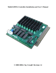
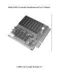
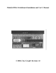
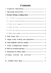
Page 1 of 6
HD-CONVERTER
USER MANUAL
MODEL GBS-8220
CGA/EGA/YUV TO VGA CONVERTER
VERSION 3.0
CONVERT OR REPLACE YOUR OLD STYLE MONITORS WITH NEWER VGA
CRTS OR LCD SCREENS QUICKLY AND EASILY!
FEATURES:
- Supports CGA/EGA/YUV signal input
- Supports VGA output 640*480,800*600, 1024*768,
1360*768
- CGA/EGA signal auto scan (15K,24K,31K)
- YUV signal auto scan (480i,576i,720i,1080i,480p,576p,720p,1080p)
- Chinese and English OSD
- Supports position control & zoom control
- True digital 24-bit A/D converter for true 16.7-million color conversion.
Supports all VGA monitor (CRT, LCD,PDP, LCD PROJECTORS…)
Page 2 of 6
The GBS-8220 is a high definition video converter board that supports a wide variety
of input signals and converts them to a VGA output signal. This board will support a
number of different devices, including classic CGA arcdade games, and convert those
signals to work on VGA CRT monitors, LCD monitors, PDP monitors, even HDTV's!
Just connect to one of the input spots shown at the bottom of the picture
above and the board will auto scan for a CGA/EGA/YUV signal. Output is through one
or both of the VGA connectors shown at the top of the board.
Power
Input signal
Output signal
User control
Dimensions
Inputs and Outputs:
DC5V 2A +/- 0.5v
14.5-16.5K
CGA/EGA 23.5-25.5K
Auto scan
30.5-32.5K
RGBHV 30.5-32.5K
Auto scan
VGA
30.5-32.5K
Auto scan
480p,576p,7
Ypbpr
Auto scan
20p,1080p
Ycbcr
Auto scan
480i,576i,72
0i,1080i
640*480,800*600
VGA
1024*768,1360*768
Input Switch, Image Zoom, Image Position,
Output Resolution ,R\G\B gain adjust.
115*105*20mm
P7 or P9
P3 or P11 or P10
P10 or P11
P10 or P11
P2
P2
P4 and P13
Menu Key
R\G\B VR
Page 3 of 6
GBS-8220 Basic directions
Step 1:
As with all game repairs make sure power is shut off and disconnected from your unit while you are
installing the board. Also check all voltages before installation. Incorrect voltages can damage both
the GBS-8220 and the game board being installed. When handling bare pcb's, care should be taken to
avoid causing damage with static electricity.
Step 2:
Find a nice place in the cabinet to mount the board with the feet included with your board. This
location should be on a vertical surface to avoid collecting dust or in a protected enclosure. The board
should be located in relatively close proximity to a power source, video source, and within reach of the
vga monitor cable.
GBS-8220 User Manual
Page 4 of 6
Step 3:
Connect video input from your old device to the GBS-8220 through P2, P3, P9, or P11. On our
Jamma harnesses and those from some cabinets and other vendors there is a 5 pin connector that can be
plugged directly into P3 as shown here:
If your harness does not have this style connection you may use the included 8 pin connector to input a
CGA, EGA, or RGBS signal. Connector P11 is shown here:
Pin 1 Red wire – Red Video input (generally the red wire going from the jamma board to the monitor, R)
Pin 2 Green wire – Green Video input (generally the green wire going from the jamma board to the monitor, G)
Pin 3 Blue wire – Blue Video input (generally the blue wire going from the jamma board to the monitor, B)
Pin 4 Grey wire – Horizontal Sync (generally the fourth or white cable going from the jamma board to the monitor, S) (S)
***If you only have one sync on your existing set up, use the grey wire as the single sync connection, not the yellow***
Pin 6 Yellow wire – Vertical Sync (generally the 5th wire going from the jamma board to the monitor if present,VS)
Pin 8 Black wire – Video Ground (generally the black wire going from the jamma board to the monitor)
Step 4:
Connect the VGA monitor to the output connection at P4 or P13 on the GBS-8220. If using two
monitors both VGA outputs may be used.
GBS-8220 User Manual
Page 5 of 6
Step 5:
Connect 5V DC with a minimum of 10 Watts available power (2 amps @ 5V) to P7 or P9. If using P9
with the 2 pin cable provided, +5V DC should be connected by the red wire and ground should be
connected with the black wire (shown in the picture below).
Step 6:
When the board is powered up, and the monitor is on, 4 blue Chinese characters will be displayed on
the screen for a short time and then the board should auto adjust to the input provided.
If no picture is seen on the screen at all:
Check to ensure proper connections of power for the board, there should be a red LED lit on the
board if proper power is being provided to the converter.
If you see the initial blue characters and then the expected picture does not appear:
1) Check that the proper power is being delivered to the video source (PCB or other device).
2) Press the auto button on the converter board.
3) Use menu button to enter the menu to manually adjust the settings.
4) Try moving the grey connection on P11 from pin 4 to pin 5 and restart the system and repeat the
steps.
Step 7:
RGB adjustment: In most cases the image you see will not be accurate for intensity levels of RGB and
may be misaligned on the screen.
To adjust image size and location press the “Menu” button on the board, select geometry and adjust the
image appropriately.
To adjust the RGB levels use a small flat head and adjust the dials shown next to the RGB inputs here:
Rotate the dials until the desired image appears, this may take a few passes of adjustment.
GBS-8220 User Manual
Page 6 of 6
OSD Menu Navigation:
Menu – Opens the OSD and serves as the “Enter” button
SW- To switch between the RGBHV/RGBS/Ypbpr connections for input
Up – Navigate up in the menu or increase a number once the value is selected with menu/enter.
Down/Auto- In the OSD this will navigate or reduce a number, if the OSD is not open then pushing
this button will put the board into scan mode to determine the input and conversion automatically.
To reset the system, hold the “Down/Auto” key for 5 seconds and release
To Change the language, press “Menu” and select option 4, English or Chinese will be present to select,
hilight the one you would like and press “Menu”.
If you have a screen that washes out or goes to black, adjust the clamp settings (Clamp st and Clamp sp
in the OSD) Settings may be reduced to get a stable image, with people reporting changes all the way
down to st=3 and sp=4, but make sure to keep the “st” less than the “sp”.