1
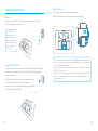
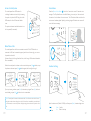
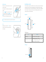
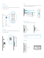
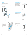
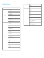
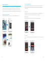
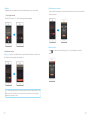
B11 PSTN/GSM
Dual Networks
Alarm System
C
2014 Chuango Security. All Rights Reserved.
Printed in China
OI: B11-UM-EN-V1.1
User Manual
Table of Contents
Package List --------------------------------------------------------------------- 01~02
Remote Control Instruction ------------------------------------------------------ 41~42
Control Panel Layout ------------------------------------------------------------ 03~04
Answering Alarm Phone Call to Start Remote Control ----------------------------- 41
Preparation before Use --------------------------------------------------------- 05~06
Remote Control by Calling Fixed Phone Number----------------------------------- 42
Power on -------------------------------------------------------------------------- 05
Remote Control by Calling SIM Card Number ------------------------------------- 42
Connect PSTN Land Line --------------------------------------------------------- 05
SMS Operation------------------------------------------------------------------- 43~44
Insert a SIM Card ------------------------------------------------------------------- 06
Disarm ----------------------------------------------------------------------------- 43
Control Panel Operation --------------------------------------------------------- 07~10
Arm (Away Arm) ------------------------------------------------------------------ 43
Alarm Control ---------------------------------------------------------------------- 07
Home Mode (Part Arm) ----------------------------------------------------------- 44
Access Control System ------------------------------------------------------------ 09
Monitor --------------------------------------------------------------------------- 44
Make Phone Calls ------------------------------------------------------------------ 09
Recording Voice Memo ------------------------------------------------------------ 44
Voice Memo ----------------------------------------------------------------------- 10
App Operation ------------------------------------------------------------------- 45~51
Function Setting--------------------------------------------------------------------- 10
Download and Install APP ---------------------------------------------------------- 45
Security Alarm Function ---------------------------------------------------------- 11~22
Control through SMS--------------------------------------------------------------- 46
Test Accessories ---------------------------------------------------------------------11
Control through GPRS Data ------------------------------------------------------- 48
Remote Control -------------------------------------------------------------------- 11
Maintenance --------------------------------------------------------------------------52
Door/Window Contact ------------------------------------------------------------- 14
FAQ ---------------------------------------------------------------------------------- 53
Pet-Immune PIR Motion Detector -------------------------------------------------- 16
Specifications -------------------------------------------------------------------- 54~55
LCD Display Contents ------------------------------------------------------------ 23~24
Disclaimer----------------------------------------------------------------------------- 56
LCD Display Menu --------------------------------------------------------------- 25~27
Settings -------------------------------------------------------------------------- 28~39
Alarm Phone Number Setup ------------------------------------------------------ 28
Add/Delete/Edit Accessories ------------------------------------------------------ 29
System Settings ------------------------------------------------------------------- 31
Check Event Logs ------------------------------------------------------------------ 39
Connect to Electronic Lock ----------------------------------------------------------- 39
Connect to CMS ---------------------------------------------------------------- 40~41
Add CMS Phone Number --------------------------------------------------------- 40
Delete CMS Phone Number ------------------------------------------------------ 40
User ID --------------------------------------------------------------------------- 40
Upload Arm/ Disarm Report to CMS Center -------------------------------------- 41
Features
100% wireless configuration, D.I.Y. installation
Stylish design with touch keypad
LCD with guide menu, easy for programming
Built-in 1,000,000 RF codes combination maintains high reliability
Support 10 remote controls, 50 wireless sensors, and 50 RFID tags
Store 6 alarm phone numbers
10 seconds voice memo and alarm voice message recordable
Disarm by RFID tags and unlock the electronic door lock
Support maximum 150 alarm event logs
Make phone calls directly
Duress code enables sending out alarm notification mutely
One group of timing arm and disarm
Support exit & entry delay
Rename all zones and RFID tags
Easy operation with phone remote control function
Arming, disarming and recording voice memo via App through SMS or GPRS
Please read this user manual carefully.
Please kindly keep this user manual for your reference when necessary.
Package List
CG-B11 Control Panel x1
The control panel is known as the “heart
and brain” for alarm system, which is used
for receiving and processing signals from
wireless sensors and remote controls. Users
can make settings freely with the keypad
and LCD display. In case of emergency, the
panel hoots on site and dials the pre-stored
alarm phone numbers automatically. When
users pick up the phone, they are able to hear alarm voice message and choose to
monitor on site or disarm the system, etc.
As a PSTN/GSM dual networks alarm system, B11 panel will switch to GSM network
automatically to call the user for alert when the PSTN network is cut off.
AC Adapter x 1
Tag-26 RFID Tag x 2
Supply power to the control panel. In
The RFID tag is for disarming the
case of power failure, two built-in
system and unlocking the
backup batteries in the panel will
electronic door lock (if connected).
support 5-hour standby.
PIR-910 Pet-Immune PIR Motion Detector x 1
Pet-Immune PIR Motion Detector is an intelligent passive
infrared motion sensor, designed to detect human movements
within an approximate range of 0 to 8 meters from the detector.
Telephone Cable x 1
Bracket for PIR Motion
Screws and Wall
Connect PSTN land line to the
Detector x 1
Plugs x 4
The detector includes fuzzy logic to minimize false alarms from
control panel. In case of
unwanted heat sources. With power saving feature, the detector
emergency, the panel will
will enter sleeping mode after the second activation within 3
hoot on site and call the pre-
minutes to save power.
stored alarm phone number
to notify users.
DWC-102 Wireless Door/Window Contact x 1
RC-80 Wireless Remote Control x 2
The Door/window contact can be installed on
The remote control is compact and
doors, windows and any other objects that open
portable; it is convenient to carry it to
and close. The sensor transmits signals to the
arm, disarm, part arm the alarm system
control panel when a magnet mounted near the
and also make an emergency call.
Brackets (Wall-Mounted and
Double-Sided Tape for
Desktop) for Control Panel x 2
Door/Window Contact x 2
User Manual x 1
sensor is moved away.
01
02
Rear Side
Control Panel Layout
MIC
Tamper Switch
Speaker
Front Side
GSM Network LED
Home Mode (Part Arm)
RFID Tag Reader /
Play Voice Memo
Disarm
Arm
Terminals for
Wired Sensors
SIM Card Slot
Landline Jack
AC Adapter
Jack
Power
ON/OFF
LCD Display
Esc
Up/Down
Backup Batteries
Enter
Output Wired Siren
(≤500mA)
Clear
LED Indicator
Call
SOS
NC Input for
Wired Sensor
(Normal Zone)
Voice Memo Button
Output for
Electronic Lock
03
04
Insert a SIM Card
Preparation before Use
This step can be ignored if GSM function is not applied.
Insert a SIM card into the card slot according to the mark and lock it.
Power on
1. Plug the output connector of AC adapter into the adapter Jack of control panel.
2. Plug the AC adapter into a wall outlet.
Note:In daily use, it is
recommended to use
external power supply.
2
The built-in rechargeable
battery should be used
only in the case of AC
power failure.
1
Note: A GSM SIM card with normal functions (calling, answering, SMS and caller display) is
required. If use App to control the alarm system through GPRS network, it is recommended
Connect PSTN Land Line
to activate a GPRS plan to save expense.
B11 is a PSTN & GSM dual networks alarm system, If there is an alarm, it will auto dial
pre-stored phone numbers though landline, or dial through GSM network when
Insert the SIM card only after the control panel is switched off. Then, switch on the control
panel so as to search signals.
If no SIM card is inserted, the control panel can only send alarm notification by calls through
landline is unavailable.
land line and users cannot remote control the control panel through App. However, other
1. Connect the smaller connector of provided telephone cable to the
functions are not affected.
2
PSTN land line interface at the back side of the panel.
2. Connect the other end of the telephone cable to the signal output
provided by PSTN land line operator.
1
05
06
Control Panel Operation
Disarm
Input user code (Default: 1234) or
admin code (Default: 123456) first,
Alarm Control
then press the [Disarm
Arm (Away Arm)
Press the [Arm
] button,
the system enters disarm state when
] button on the
control panel, the system enters Arm
one beep is heard and the disarm
LED Indicator lights on.
state when one beep is heard and the
arm LED Indicator lights on.
Note: If Entry/Exit Delay is activated, all
zones except the 24-hour zone will enter
arm state after the set delay time.
Emergency Call
When the LCD display is activated,
Hold the [
] button for 3 seconds
the system goes into emergent
alarming state with siren hooting,
Home Mode (Part Arm)
Press the [Home Mode
] button on
the control panel, the system enters
meanwhile the panel will auto dial
pre-stored alarm phone numbers.
home mode when one beep is heard
and the home mode LED Indicator
lights on. All the normal sensors are
armed except the home mode sensors
which are disarmed, so that users can
move freely at home.
07
08
Voice Memo
Access Control System
The control panel has a RFID reader for
Press the [Record Voice Memo
unlocking the electronic door lock by disarming
message. The Play Voice Memo circle will be flashing to remind you. Users can touch
] button for 3 seconds to record 10 seconds voice
the system. Just place the RFID tag close to the
the center of circle to listen to the voice memo. The LED indicator blacks out when the
RFID reader, the blue LED indicator flashes
voice memo has been played. Replay by touching it again.The latest voice memo will
once.
cover the former message.
The system is disarmed and the electronic door
lock is opened (If connected).
Make Phone Calls
1
2
3
4
The control panel has a built-in communication module. If the PSTN land line is
connected or SIM card is connected properly, and the credit is enough, you can use
the panel to make calls.
(System will auto dial through land line first, or dial through GSM network when land
line is unavailable ).
When the control panel is in disarm or home mode state, press [Call
the phone number and press [Call
] button, input
Function Setting
] button again, the line will get through.
If you input wrong numbers, press [Esc] button and input again. Press [Esc] button to
cancel dialing or press [Call
] button to end a conversation.
Note: If control panel is connected with extension line, 0# or 9# need to be added in front of
the phone number when making phone calls. if the land line is unavailable, system will switch
to GSM network, user can make phone calls by inputting phone number directly without 0# or
9#.
Input the admin code (Default: 123456), and then press [Enter] to enter setting menu.
Up
Down
09
Enter
Esc
Confirm
Back to last step
10
Arm
Security Alarm Function
Press the [Arm
] button, the system enters
arm state when one beep is heard and the
arm LED on the control panel is on.
Test Accessories
Our accessories can work only with our control panels, can not work with other brands.
Note: If Exit Delay is activated, all zones except
the 24-hour zone will enter arm state after the
Remote Control
set delay time.
RC-80 remote control is dainty and delicate, easy to carry. It can be attached to your
key ring, or just put into your pockets or purses.When you are about to exit or entry
the house, you can use it to arm or disarm the system. In case of emergency, just press
the [SOS] button, the alarm will be activated immediately.
Disarm
Press the [Disarm
] button on the remote
control, the system enters disarm state when
Appearance
two beeps are heard and the disarm LED on
the control panel is on.
LED Status Indicator
Stay
When alarm is activated, the siren will hoot.
Press the [Disarm
Arm
Disarm
Panic
] button, the system is
disarmed . But the LED indicator of triggered
zone keeps flashing for further checking.
Press [Disarm
] button again, the alarming
zone indicator goes out.
Home Arm (Part Arm)
Press [Stay
] button on the remote control,
the system enters home mode when one beep
is heard and the home mode LED is on. All the
normal sensors are armed except the home
mode sensors which are disarmed, so that
users can move freely at home.
11
12
Mute Operation
Door/Window Contact
When arm or disarm the system, the siren will
The door/window contact can be installed on doors, windows, and any other objects that
can open and close. The sensor transmits signals to the control panel when a magnet
mounted near the sensor is moved away. External input for wired accessory is available at
the N/C interface. The tamper protection ensures that sabotage attempts to move the
contact will result in an alarm activation.
beep accordingly.
If siren beep is not needed, please operate as
follows:
Press [Stay
] button on the remote control
for 1 second, then press [Arm
] or [Disarm
] button. The siren is armed or disarmed
Appearance
in mute without disturbing other people.
LED Status Indicator
Note: If wireless strobe sirens are used, they will not sound either.
SOS
Magnet
Transmitter
Whenever you press the [SOS] button on
the remote control, the system will alarm
immediately.
LED Indication
Meaning
LED
Blinks once
Door/Window contact is triggered
Blinks once per 3 seconds
Low battery indication, LCD shows:
Sensor 1-50(Sensor Name) Low Battery. Please
change the batteries immediately
PCB Layout
13
AA 1.5V LR6
Tamper switch
14
Test
Pet-Immune PIR Motion Detector
1. Press the back cover and slide down to remove the back cover.
2. Remove the insulating strip. The contact works immediately.
3. Press the [Arm ] button on the remote control. The system switches to the arm
status. Separate the transmitter and magnet. The LED is on and the panel alarms. It
indicates that the sensor works properly.
Note: There are triangle marks on the side of the transmitter and magnet. Make sure the
triangle marks face each other and within the range of 1 cm.
The detector adopts digital dual-core fuzzy logic control processing technology and
intelligent analysis algorithm, effective resolution of interfering signal and human
movement signal, preventing false alarm. It features automatic temperature
compensation and resistance to flow technology, adapting to environmental and
temperature change. It can detect human movement within the 8-meter cone space,
suitable for halls, hallways, etc. The detector features pet immunity for small animals
up to 25kgs.
Appearance
Installation
1. Detecting lens
3
Mount the transmitter on the frame and the magnet on the door or window. Make
sure the magnet is on the right side of the transmitter. Secure the transmitter and
magnet on the desired locations with double-sided tapes or screws.
2. LED
3. Snap joint
4. Test button
4
5. Installation bracket
2
1
5
LED Indication
Blinks continuously: Under self-testing state.
Blinks once: Intruder is detected.
Blinks twice: 3 minutes testing is finished, enters power saving mode.
Blinks once per 3 seconds: Low battery indication, LCD shows: Sensor 1-50(Sensor
Name) low battery, please change the batteries immediately.
PCB Layout
Infrared sensor
LED ON / OFF
Infrared sensor
AA 1.5V LR6
15
Tamper switch
AA 1.5V LR6
Note: Make sure the transmitter and
magnet works properly on the desired
locations. If a metal door is installed,
place spacers under the transmitter
and magnet. Do not apply the contact
to a rolling shutter. Purchase dedicated
contacts for rolling shutters when
necessary.
Note: If the detector is disassembled,
system will sound immediately,and
LCD shows "Sensor 1-50(Sensor
Name) Sensor Tamper".
Zone setting
16
Test
Working Mode
Testing mode
1. Remove the insulating strip
Press the buckle to open the back
cover. Remove the insulating strip.
After 30-second self-testing, the
detector switches to the testing mode.
After self-testing, the detector enters
testing mode, and detects once
every 10 seconds. After 3 minutes,
the LED blinks twice, and the
detector enters power saving mode.
2. Arm
Press the [Arm ] button on the
remote control. The system is in the
armed state.
Hold the test button and load the
battery, then release the test button,
the detector stands in testing mode,
it keeps detecting once every 10
seconds. Exits this status by
reloading the battery without
holding the test button.
Power saving mode
The product features power-saving
design. If the detector detects human
movement twice in 3 minutes, it will switch
to the sleeping state to save power. At this
time, the LED will not blink and no alarm.
After no movement within the next 3
minutes, the detector switches back to the
working state automatically.
Note: After the detector is in the sleeping state,
Case 1:
Initial start
and then arm.
Case 2: Press
the test button
and then arm.
3 minutes later
3. Trigger the alarm
Keep pressing the test button at the back until the siren sounds.
Sleep after
detecting human
movement twice
No human movement
within 3 minutes
ensure no human movement within 3 minutes;
otherwise, the detector remains sleeping.
In the sleeping state, it is recommended that
Switch from
sleep to arm.
you leave the room after arming the system.
Ensure no human movement in 3 minutes.
Then, go into the room, the system alarms
immediately.
Note: The testing mode sustains for 3 minutes. Then, the LED blinks twice, indicating the
detector is in the power saving mode.
17
18
3. Testing
Installation
1. Choose installation place
Press the test button on the back of the detector, walk in the detection scope and watch
the LED indication to make sure the detector is working.
It is recommended to mount it at the height of 2m from the ground. (For installation
notices, please see page 21-22)
2m
4. Adjust the bracket angle
Adjust the bracket angle to achieve the best detection effect.
Ground
2. Fix the detector
Side view
Top view
Fix the installation bracket on the wall with screws, and then fit the groove at the back
of the detector on the bracket.
Note: If pet-immune function is used, please do not adjust the angle up or down, but keep it
parallel with the wall.
Detection Scope
0m
2m
4m
6m
8m
2m
110°
Top view
0m
Side view
19
20
Installation Notices
Pay attention to the following during installation:
1. Mount the detector to a location close to the entry or exit
The detector aims at preventing intrusion. Detecting human movement at the entry or
3. Avoid facing to glass windows or doors
Strong light interferes with detection
sensitivity. In addition, complicated
situations, such as traffic flow, stream of
people, also should be avoided.
exit is critical for security.
4. Avoid facing or positioning close to heat
Avoid facing or positioning close to
heat sources such as heat extraction
units, heaters, air conditioner,
ON
microwave oven, refrigerator, which
may cause false triggering.
2. Mount the detector in a proper angle
The installation angle affects sensitivity
directly. The sensitivity is optimal when
the walk direction is vertical to the
infrared direction. Choose the best
location and angle according to the
actual situation and detection scope
diagram.
21
5. Avoid facing to swinging objects
Swinging objects may also trigger false
triggering. Besides, if there are two
detectors covering the save scope,
adjust the locations to prevent crossinterference.
22
LCD Display Contents
Arm or Disarm
Display content
System Status
Alarm
SOS
Line Disconnect
AC Power Failure
Alarm
Linecut
Host Low Battery
GPRS Connected
Stand-by
Sensor 1-50(Sensor Name)
Low Battery
NO SIM CARD
GPRS Connecting
GPRS Disconnected
System Arm
SMS
Disarm
SMS
Home Arm
Alarm
Panel Tamper
Alarm
Alarm
Wired Sensor
Sensor1-50(SensorName)
SensorTamper
Alarm
Sensor 1-50(Sensor Name)
System Disarm
System Home Arm
Remote Arm
Remote Disarm
Arm or Disarm
Remote Home Arm
RFID 1-50(RFID Name)
Disarm
GPRS
Arm
GPRS
Disarm
GPRS
Home Arm
SMS
Arm
23
24
LCD Display Menu
Date
Date And
Time
When LCD is activated, input the admin code (Default: 123456), and then press [Enter]
Date Format
Time
to enter setting menu.
Entry Delay <000S>
Main Menu
Sub Menu 1
Sub Menu 2
Entry Exit
Delay
Sub Menu 3
Exit Delay <000S>
Alarm Number1-6
Add Phone
Number
Phone
Numbers
Backlight
Time
<20S>
CMS Number1-2
Alarm Number1-6
Del Phone
Number
CMS Number1-2
Auto Arm/
Disarm
Add
Remote &
Keypad
Delete
ALL
Delete
Edit Name
Edit Welcome
ALL
RFID (01-50)
RFID (01-50)
Add
Delete
Accessories
Auto Disarm Time
<00:00:00>
Remote (01-10)
Add
RFID Tag
System
Settings
Auto Arm Time
<00:00:00>
ALL
Linecut
Alarm
On
Off
Keypad
Tones
On
Off
Sensor (01-50)
Admin Code
Input 6 Digits
<Default Code 123456>
User Code
Input 4 Digits
<Default Code 1234>
Duress Code
Input 4 Digits
<Default Code 1111>
Sensor (01-50)
Wireless
Sensors
Edit Sensor Type
Edit
(Normal Sensor, 24 Hour
Access
Code
Sensor, Delay Sensor,
Home Sensor)
Edit Sensor Name
Test Mode
25
26
Settings
Ringing Times
Alarm Message
Record
When LCD is activated, input the admin code (Default: 123456), and then press [Enter]
to enter setting menu.
Siren On/Off <On/Off>
Wired Siren
Important: The default language of this alarm system is English, you can change in the
Arm/Disarm Tone <On/Off>
[Language] menu of [System Setting].
Siren On/Off <On/Off>
Wireless Siren
Arm/Disarm Tone <On/Off>
1. Alarm Phone Number Setup
User can set 6 user phone numbers and 2 CMS phone numbers. When connecting to
Siren Setup
CMS, system will dial CMS phone number to upload Contact ID reports while alarming
Siren On/Off <Off/Low/High>
System
Settings
and then dial 6 user phone numbers in sequence one by one. System will dial all the
Built-in Siren
user phone numbers in 3 cycles until the phone is answered together with any
Arm/Disarm Tone <On/Off>
operation on phone buttons.
Siren Alert Time
<300S>
User ID<1234>
Input 4 Digits
Arm Upload
On
Off
Disarm Upload
On
Off
Add Alarm Phone Number
1
Log on the menu, choose “Phone Numbers”, press [Enter].
2
Press [
] or [
] , choose “Add Phone Number”, press [Enter].
Press [
] or [
] , choose “Alarm Number1~6”, press [Enter].
3
4
Input alarm phone numbers in order, press [Enter]. If group extended telephone
number is used, 0# or 9# need to be added in front of the phone number.
Note: If user wants to check or edit the stored phone number, enter “Alarm Number1~6” to
check and edit.
Language
Reset
Delete Alarm Phone Number
History
1
2
3
4
Log on the menu, choose “Phone Numbers”, press [Enter].
Press [
] or [
] , choose “Delete Phone Number”, press [Enter].
Press [
] or [
] , choose “Alarm Number1~6”, press [Enter].
Delete the alarm phone numbers in order, press [Enter] again.
Note: If user wants to set CMS center phone number, please refer to “Connect to CMS Center”.
27
28
Delete
2. Add/Delete/Edit Accessories
The control panel only receives signal from accessories after they are connected to the
If user wants to delete the added RFID cards or tags, please choose “Delete” in step
control panel.
as above and press [Enter]. Then choose to delete all or specific RFID cards or tags,
3
press [Enter] again.
Add/Delete Remote Controls or Wireless Keypads
Edit
Add
If user wants to rename the added RFID cards or tags, please choose “Edit Name” in
1
Log on the menu, press [
] or [
] , choose “Accessories”, press [Enter].
2
Press [
] or [
] , choose “Remote & Keypad”, press [Enter].
3
Press [
] or [
] , choose “Add”, press [Enter].
4
LCD display will show “Please connect”, press any button from the remote control to
step
3
as above and press [Enter] , then input the name.
Note: press the [*] button of the control panel to clean when wrong input.Press the [ESC] to exit.
enable signal transmitting to the control panel. When a beep is heard, LCD display will
show “Remote (01-10)”, connection succeeded.
Add/Delete/Edit Wireless Sensors
When 2 beeps are heard, it means this accessory has connected with control panel
Add
before.
1
Note: When adding wireless keypad to control panel, please enter access code and then
press "arm" or "disarm" button on the wireless keypad. When a "beep' is heard, the system
is connected to the panel successfully.
Log on the menu, press [
] or [
] , choose “Accessories”, press [Enter].
2
Press [
] or [
] , choose “Wireless Sensors”, press [Enter].
3
Press [
] or [
] , choose “Add”, press [Enter].
4
LCD display will show “Please connect”, trigger the detector once to make it send
wireless signal to the control panel. When a beep is heard, LCD display will show
“Sensor (01-50)”, connection succeeded. When 2 beeps are heard, it means this
Delete
accessory has connected with control panel before.
If user wants to delete the added remote controls or wireless keypads, please choose
“Delete” in step
3
as above and press [Enter]. Then choose to delete all or specific
Delete
remote controls or wireless keypads, press [Enter] again.
If user wants to delete the added sensors, please choose “Delete” in step
3
as above and
press [Enter]. Then choose to delete all or specific wireless sensors, press [Enter] again.
Add/Delete/Edit RFID Tags
Edit
Add
1
Log on the menu, press [
] or [
Edit Type of Sensors
] , choose “Accessories”, press [Enter].
2
Press [
] or [
] , choose “RFID Tag”, press [Enter].
1
Log on the menu, press [
3
Press [
] or [
] , choose “Add”, press [Enter].
2
Press [
] or [
] , choose “Wireless Sensors”, press [Enter].
] or [
] ,choose “Accessories”, press [Enter].
4
LCD display will show “Please connect”, place the RFID tag close to the RFID reader on
3
Press [
] or [
] , choose “Edit”, press [Enter].
the control panel. When a beep is heard, LCD display will show “RFID (01-50)”,
4
Press [
] or [
] , choose “Sensor 01-50”, press [Enter].
connection succeeded. When 2 beeps are heard, it means this accessory has
5
Press [
] or [
] , choose “Edit Sensor Type”, press [Enter].
connected with control panel before.
6
Press [
] or [
] , choose one type of “Normal Sensor/ 24 Hour Sensor/ Delay
Sensor/ Home Sensor”, press [Enter].
29
30
Normal Sensor: In arm mode, when normal sensors are triggered, system will alarm. In
disarm mode, when normal sensors are triggered, system will not alarm.
24 Hour Sensor: Under any circumstances, when 24 hour sensors are triggered, system
will alarm at once.
Delay Sensor: In arm mode, when delay sensors are triggered, system will alarm after
the set time if the entry delay time was set before. (For "Entry Delay", please refer to
page 32).
Home Sensor: In home mode, only normal sensors will be triggered for alarming while
home sensors will not be triggered. This will allow user to move freely at home.
Names of Sensors
If user wants to rename the sensors, please choose “Edit Sensor Name” in step 5 and
press [Enter]. Then input the sensor name.
Date Format
1
Log on the menu, press [
2
Press [
] or [
] , choose “Date and Time”, press [Enter].
] or [
] , choose “System Settings”, press [Enter].
3
Press [
] or [
] , choose “Date Format”, press [Enter].
4
Press [
] or [
] , choose format, press [Enter].
Time
The default time is set on 24 hours standard.
1
Log on the menu, press [
2
Press [
] or [
] , choose “Date and Time”, press [Enter].
] or [
] , choose “System Settings”, press [Enter].
3
Press [
] or [
] , choose “Time”, press [Enter].
4
Input current time, press [Enter].
Entry and Exit Delay
Note: press the [ * ] button of the control panel to clean when input wrong. Press the [ESC] to
exit.
If user is not used to taking along with the remote control, entry and exit delay could
be set.
When entry and exit delay is set, user could exit the house in set time period, then
Test Mode
system will be armed automatically; when user is back without disarming the system,
Test if the sensors are connected successfully to the control panel.
entry delay will allow time for user to disarm the system. Otherwise, the system will take
1
Log on the menu, press [
2
Press [
3
Please trigger coded sensors in order, the sensors will transmit signals to control panel.
Entry delay is set to leave time for user to disarm the system when delay sensors are
When 3 beeps are heard, LCD display will collect the triggering time of the sensors.
triggered.
] or [
] or [
] , choose “Accessories”, press [Enter].
this as an intrusion and send out alarming alert.
] , choose “Test Mode”, press [Enter]. LCD display will show “Yes?”,
press [Enter] again to start testing mode for 10 minutes.
Entry Delay
Then you can count the connected sensors based on the numbers displayed on the
1
Log on the menu, press [
LCD screen. Exit by pressing [Esc] button.
2
Press [
] or [
] , choose “Entry Exit Delay”, press [Enter].
3
Press [
] or [
] , choose “Entry Delay”, press [Enter].
4
Input time for entry delay; press [Enter] for confirmation.
3. System Settings
] or [
] , choose “System Settings”, press [Enter].
Entry delay time is calculated on seconds; default is 0 second (off ); setup range is 0Date and Time
999 seconds.
Date
1
Log on the menu, press [
] or [
] , choose “System Settings”, press [Enter].
2
Press [
] or [
] , choose “Date and Time”, press [Enter].
3
Press [
] or [
] , choose “Date”, press [Enter].
4
Input date, press [Enter].
31
Note: The zone setting of delay sensor, please refer to page 31.
32
Exit Delay
Timed Disarm
Exit delay is set to leave time for user to exit before the system is armed.
1
Log on the menu, press [
] or [
1
Log on the menu, press [
] or [
] , choose “System Settings”, press [Enter] for
confirmation.
] , choose “System Settings”, press [Enter].
2
Press [
] or [
] , choose “Entry Exit Delay”, press [Enter].
2
Press [
] or [
] , choose “Auto Arm/Disarm”, press [Enter].
3
Press [
] or [
] , choose “Exit Delay”, press [Enter].
3
Press [
] or [
] , choose “Auto Disarm Time”, press [Enter].
4
Input time for exit delay; press [Enter] for confirmation.
4
Input exact time for disarming; press [Enter].
Exit delay time is calculated on seconds; default is 0 second (off ); setup range is 0-999
seconds.
Edit Greeting Message
When greeting message is set; turn on the alarm system or activate the touch keyboard;
Note: Once delay time is set, when arm the system, one beep will be heard every second to
remind the user to leave , the reminding rhythm will speed up in the last 15 seconds.
the greeting message will be shown on LCD display.
1
Log on the menu, press [
2
Press [
[
Backlight Time
] or [
] , choose “System Settings”, press [Enter].
] , choose “Edit Welcome”, press [Enter] to define the greeting message.
] means to delete, [
] means to space, [
] means to move backward, [
] means
to move forward.
User can set standby time of the backlight on the blue LCD display accordingly.
1
Log on the menu, press [
2
Press [
3
Input time for backlight time; press [Enter].
When linecut alarm function is on, the control panel will alarm once the PSTN land line
Backlight time is calculated on seconds; default is 20 seconds; setup range is 01-99
is cut or pulled out even if the built-in siren was set to mute..
] or [
] or [
] or [
] , choose “System Settings”, press [Enter].
Line Cut Alarm
] , choose “Backlight Time”, press [Enter].
seconds.
Turn On/Off Linecut Alarm
Timed Arm / Disarm
User can set timed arm and disarm according to daily schedule to avoid repeated
1
Log on the menu, press [
2
Press [
] or [
] , choose “Linecut Alarm”, press [Enter].
3
Press [
] or [
] , choose “On” or “Off”, press [Enter].
operation.
] or [
] , choose “System Settings”, press [Enter].
“On” is to turn on the linecut alarm; “Off” is to turn off the linecut alarm.
Default setting is “On”, the linecut alarm is on.
Timed Arm
1
Log on the menu, press [
2
Press [
] or [
] , choose “Auto Arm/Disarm”, press [Enter].
] or [
] , choose “System Settings”, press [Enter].
Keypad Tone
3
Press [
] or [
] , choose “Auto Arm Time”, press [Enter].
User can turn on/off keypad tone accordingly.
4
Input exact time for arming; press [Enter].
Turn On/Off Keypad Tone
1
Log on the menu, press [
] or [
] , choose “System Settings”, press [Enter].
2
Press [
] or [
] , choose “Keypad Tone”, press [Enter].
3
Press [
] or [
] , choose “On” or “Off”, press [Enter].
“On” is to turn on the keypad tone; “Off” is to turn off the keypad tone. Default setting
is “On”, keypad tone is on.
33
34
Ringing Times for Remote Phone Control
Access Code
All the alarm panels are with default user code, admin code and duress code. Please
After the set ringing times, user can make system settings from remote calling, such as
change all codes before using and keep your codes secret.
arming/disarming the system.
Admin Code
With admin code, user can arm and disarm, make system settings as well as reset codes
1
Log on the menu, press [
2
Press [
3
etc.
] or [
] or [
] , choose “System Settings”, press [Enter].
] , choose “Ringing Times”, press [Enter].
Input 5~9 for ringing times, press [Enter].
Default setting is 5 times.
1
Log on the menu, press [
2
Press [
] or [
] , choose “Access Code”, press [Enter].
] or [
] , choose “System Settings”, press [Enter].
3
Press [
] or [
] , choose “Admin Code”, press [Enter].
4
LCD display will show “Input 6 Digits”, then input 6 digits for code, press [Enter].
Alarm Message
User can leave a 10-second voice message when control panel makes call to user's
stored phone number, voice recording will be repeatedly played to notify the intrusion.
(Default Admin Code: 123456)
5
Input the new admin code, press [Enter].
Record Alarm Message
1
User Code
Log on the menu, press [
2
] or [
] , choose “System Settings”, press [Enter].
Press [
] or [
] , choose “Access Code”, press [Enter].
3
Press [
] or [
] , choose “User Code”, press [Enter].
4
LCD display will show “Input 4 Digits”, then input 4 digits for code, press [Enter].
] , choose “System Settings”, press[Enter].
Press [
] or [
] , choose “Alarm Message”, press [Enter].
Press [
] or [
] , choose “Record”, press [Enter].
4
LCD display will show “Record 10s Voice” to remind you of the 10 seconds voice
recording, press [Enter].
5
Start voice recording for 10s until the system stops automatically, or press [Enter] to
stop recording.
(Default User Code: 1234)
5
] or [
3
With user code, user can set arm, home mode and disarm the alarm system.
1
Log on the menu, press [
2
Input the new user code, press [Enter].
Siren Setup
Duress Code
Users can turn on/off wired siren, wireless siren, built-in siren as arm/disarm beep and
In case of emergency, when user is violently requested to disarm the system, it's
set siren ringing time.
recommended to use the duress code to disarm the alarm system. The panel will
Wired Siren
silently dial alarm telephone numbers stored.
Wired siren is connected to the control panel by wire.
1
Log on the menu, press [
2
Press [
] or [
] , choose “Access Code”, press [Enter].
3
Press [
] or [
] , choose “Duress Code”, press [Enter].
4
LCD display will show “Input 4 Digits”, then input 4 digits for code, press [Enter].
(Default Duress Code: 1111)
3
Press [
] or [
] , choose “Wired Siren”, press [Enter].
5
Input the new duress code, press [Enter].
4
Press [
] or [
] , choose “Siren On/Off”, press [Enter].
5
Press [
] or [
] , choose “On” or “Off”, press [Enter].
] or [
] , choose “System Settings”, press [Enter].
Turn On/Off Wired Siren
1
Log on the menu, press [
2
Press [
] or [
] or [
] , choose “System Settings”, press [Enter].
] , choose “Siren Setup”, press [Enter].
“On” is to turn on the wired siren; “Off” is to turn off the wired siren.
Default setting is “On”; the wired siren is on.
35
36
Turn On/Off Arm/Disarm Beep for Wired Siren
Built-in Siren
1
Log on the menu, press [
Built-in siren is the siren inside the control panel.
2
Press [
] or [
] , choose “Siren Setup”, press [Enter].
3
Press [
] or [
] , choose “Wired Siren”, press [Enter].
4
5
Press [
Press [
] or [
] or [
] or [
] , choose “System Settings”, press [Enter].
] , choose “Arm/Disarm Beep”, press [Enter].
] , choose “On” or “Off”, press [Enter]
“On” is to turn on arm/disarm beep for wired siren; “Off” is to turn off arm/disarm beep
for wired siren.
Turn On/Off Built-in Siren
1
Log on the menu, press [
2
Press [
] , choose “System Settings”, press [Enter].
Press [
] or [
] , choose “Built-in Siren”, press [Enter].
4
Press [
] or [
] , choose Siren Siren On/Off, press [Enter].
Press [
] or [
] , choose Off/Low/High, press [Enter]
5
Choose "Low" or "High" to adjust the volume; "Off" is to turn off the built-in siren.
The default setting is "Low".
Wireless Siren
Wireless siren is connected to control panel through wireless connection.
Turn On/Off Wireless Siren
1
Log on the menu, press [
2
Press [
] or [
] , choose “System Settings”, press [Enter].
Turn On/Off Arm/Disarm Beep for Built-in Siren
1
Log on the menu, press [
2
Press [
] or [
] , choose “Siren Setup”, press [Enter].
3
Press [
] or [
] , choose “Built-in Siren”, press [Enter].
] , choose “Siren Setup”, press [Enter].
Press [
] or [
] , choose “Wireless Siren”, press [Enter].
4
Press [
] or [
] , choose “Siren On/Off”, press [Enter].
5
Press [
] or [
] , choose “On” or “Off”, press [Enter]
3
] or [
] , choose “Siren Setup”, press [Enter].
3
Default setting is “On”; arm/disarm beep is on.
] or [
] or [
] or [
] , choose “System Settings”, press [Enter].
4
Press [
] or [
] , choose “Arm/Disarm Beep”, press [Enter].
5
Press [
] or [
] , choose “On” or “Off”, press [Enter]
“On” is to turn on arm/disarm beep for built-in siren; “Off” is to turn off arm/disarm beep
for built-in siren. Default setting is “On”; arm/disarm beep is on.
“On” is to turn on the wireless siren; “Off” is to turn off the wireless siren.
Default setting is “On”; the wireless siren is on.
Set Ringing Time for All Sirens
Turn On/Off Arm/Disarm Beep for Wireless Siren
1
Log on the menu, press [
1
Log on the menu, press [
2
Press [
] or [
] , choose “Siren Setup”, press [Enter].
2
Press [
] or [
] , choose “Siren Setup”, press [Enter].
3
Press [
] or [
] , choose “Siren Alert Time”, press [Enter].
3
Press [
] or [
] , choose “Wireless Siren”, press [Enter].
4
Input the ringing time, press [Enter].
] or [
] , choose “System Settings”, press [Enter].
] or [
] , choose “System Settings”, press [Enter].
4
Press [
] or [
] , choose “Arm/Disarm Beep”, press [Enter].
Siren ringing time is calculated as seconds, default setting is 300 seconds. If 0 second
5
Press [
] or [
] , choose “On” or “Off”, press [Enter]
is set, siren will not ring.
“On” is to turn on arm/disarm beep for wireless siren; “Off” is to turn off arm/disarm
beep for wireless siren.
Default setting is “On”; arm/disarm beep is on.
37
38
Connect to CMS
User ID for CMS
Please see details at Page 40: Connect to CMS
Please ignore this step if users don't need to connect to CMS center.
Upload Arm Report
When connected to CMS center, control panel will upload contact ID to CMS center
Please see details at Page 41: Connect to CMS
automatically once intrusion is detected.
Upload Disarm Report
Add CMS Phone Number
Please see details at Page 41: Connect to CMS
When CMS center phone no. is stored, the control panel will auto dial to CMS center
automatically when alarm.
Reset
1
1
2
Log on the menu, press [
Press [
] or [
] or [
] , choose “System Settings”, press [Enter].
] , choose “Reset”, press [Enter] to reset the system to default setting.
Log on the menu, choose “Phone Numbers”, press [Enter].
2
Press [
] or [
] , choose “Add Phone Number”, press [Enter].
3
Press [
] or [
] , choose “CMS Number1”or “CMS Number2”, press [Enter].
4
Input CMS phone no, press [Enter]. If group extension telephone no. is used to connect
Note: All system settings will be restored to default setting. Reset will not delete the accessories
to the CMS center, please add 0# or 9# before the phone no. you plan to store.
that has already coded to the control panel.
Note: If user wants to check or edit the pre-stored phone no., enter “CMS Number1~2” to check or
If user forget the admin code and cannot setup the system, please contact local
edit.
distributors.
Delete CMS Phone Number
4. Check Event Logs
Log on the menu, choose “Phone Numbers”, press [Enter].
Users can check the event logs freely. 150 event logs are traceable.
1
1
Log on the menu, press [
2
Press [
] or [
] , choose “Del Phone Number”, press [Enter].
2
Press [
3
Press [
] or [
] , choose in order “CMS Number1~2”, press [Enter].
4
Delete stored CMS phone no., Press [Enter].
] or [
] or [
] , choose “History”, press [Enter].
] , choose the event log you need to track, press [Enter]. Relevant
event log time and alarm way will be shown.
Note: Hold [
] or [
User ID
] to skip the event logs.
It is supplied by CMS center. After it is stored, CMS center can exactly know user’s
location according to the ID number.
Connect to Electronic Lock
1
Log on the menu; press [
2
Press [
3
LCD display will show “Input 4 Digits”, input 4 digits user ID, press [Enter].
] or [
] or [
] , choose “System Settings”, press [Enter].
] , choose “User ID”, press [Enter].
Please ignore this if user is not intended to put this alarm as access control.
This alarm only sends on/off signal to electronic door lock, please refer to related
electronic door lock manual for details.
39
40
Upload Arm/ Disarm Report to CMS Center
Remote Control by Calling Telephone Number
When this function is enabled, all arm/disarm reports will be uploaded automatically to
1
CMS center, so that CMS center can know the status of the alarm system.
1
After the User ID is set, press [
] or [
] to choose “Arm Upload” or “Disarm Upload”,
press [Enter].
] or [
Call the telephone number of alarm system. After getting through, input user code or
admin code, and press [#] to confirm.
2
Users can choose the related instruction to make remote control operation. (See
instruction table below). If there is no operation within 30 seconds, the system will
2
Press [
3
When choosing “Off” during setup
] , Choose “On”, press [Enter].
2
hang up.
, press [Enter], arm/ disarm report will not be
uploaded to CMS center.
Remote Phone Control Instruction Table
Phone
Buttons
Contact ID Reports
Event
Event Code
Event Code
Explanation
Function
Event
Press [
]
Arm the system
Arm succeed
]
Disarm the system
Disarm succeed
3401
Arm
1137
Control panel tamper alarm
Press [
1401
Disarm
1144
Sensor tamper alarm
Press [
]
Monitor on site
Press [*] to prolong monitor time
1409
Disarm by RFID tag
1140
Press [
]
Turn on siren
Deter the intruders
1132
PIR detector alarm
1133
Normal zone alarm
24H zone alarm
Press [
]
Siren stops ringing
Door contact alarm
1384
Sensor low battery
Turn off siren
1131
Emergency call
1302
Control panel low battery
]
Turn on relay
1100
Press [
1120
Duress alarm
1301
Control panel AC failure
Press [
]
Turn off relay
3456
Home mode (part arm)
Press [
]
To exit Remote Phone Control
Remote Control Instruction
Available when relay is used
Or hang up the phone
Remote Control by Calling SIM Card Number
The system will enter monitor state directly when stored phone number called the SIM
card number of control panel. User is able to continue the operation by input relative
Users can operate the system by the control panel or remote control. Besides, using
command. While any phone number can proceed this function without phone number
phone call, SMS or App on the phone can also operate the system remotely.
is stored. So, it is command to store the phone number at the first beginning of the
Phone remote control can be achieved through two ways:
setting.
Answering Alarm Phone Call to Start Remote Control
When an alarm occurs, the control panel will call the stored phone numbers. When
answering the call, the user will hear the recorded voice message firstly. Then you can
press the telephone keys to operate the system remotely.(See instruction table on the
next page) The control panel will call these numbers for three rounds at most. when
user pick up with key operation, control panel stops dialing. if not, control panel keeps
dialing until three rounds are finished.
41
42
SMS Operation
Home Mode (Part Arm)
In home mode, detectors setting to home mode zone are in disarmed status; the other
detectors are still in armed status. That is, you can move freely in the home mode zone;
You can control the system by sending SMS commands to the SIM card No. SMS is
however, the rest areas are still being protected.
charged according to telecom operator.
Any phone number can send SMS to control the system by default, after you store
2
alarm phone numbers to the control panel, system accepts only the commands from
these numbers.
System in home mode.
Disarm
This is to disarm the system. In disarmed status, the detectors (except those accessories
in the 24-hour zone) will not trigger an alarm when detecting intrusion.
Monitor
This is to monitor the site remotely by call-back from the control panel.
0
After the control panel receives the SMS, it calls your phone number. Then, you can
answer the call and monitor (listen in) the site.
System disarmed.
3
Arm (Away Arm)
This is to arm the system. In armed status, the system will trigger an alarm when
Recording Voice Memo
detecting intrusion.
This is to record a 10-second voice memo by call-back from the control panel.
After the control panel receives the SMS, it calls your phone number. Answer the phone
1
System armed.
43
and then you can start to record a 10-second voice memo. The control panel will hang
up phone after 10 seconds.
4
44
App Operation
Control through SMS
This system can be controlled through SMS or GPRS interface on APP. If user choose
Any phone number can operate the system through APP by default, after you stored
alarm phone numbers on the control panel, system accepts only the commands from
these numbers.
SMS: for iPhone, the interface of sending SMS will display. For Android smart phones,
SMS will be directly sent to the number of the control panel without interface redirection.
1. Add accounts
Adding accounts enables you to bind the alarm systems to your smart phone. You can
Download and Install APP
Search keywords “B11 alarm” in Apple Store or Google Play, downloads it for free.
add more accounts to control several B11 alarm systems on one phone.
① Enter [Accounts]
Tap B11 APP, choose [SMS], and then enters account management interface.
② Add account
Tap [ + ], input the SIM card number of the control panel on [Mobile Number], and then
tap [OK].
B11
45
46
2. Operations on main menu
Control through GPRS Data
Tap the SIM card number of the control panel to enter the main menu, user can
perform disarm, arm, home arm, monitor and leave voice memo.
APN Setting
Some SIM cards need to set APN to open GPRS function. If the GPRS function of the
SIM card in B11 doesn’t work out. Do as follow:
Send 'APN' to the SIM card in the control panel; you’ll get a message back. Forward
and fill in related APN, username and password,, then send it back. You’ll get a
message 'OK' from the SIM card in the control panel to notify you that the setting is
successful. Turn off the panel and restart, then you can operate the APP via GPRS
freely.
For instance, for SIM card from Vodafone in Netherlands, there is no username and
password, leave it as it is. A message replied ’OK’, means the setup is successful.
APN
3. Delete accounts
iPhone: Tap [EDIT], choose the account number, tag [
] to confirm deletion.
APN:
User name:
Password:
APN:live.vodafone.com
User name:
Password:
Android phone: Tap [EDIT], press and hold the account number until the dialog box
appears, tap [OK] to confirm deletion.
OK
Note: The APN setting varies in different countries. Consult the local operator on how to set the
APN correctly.
47
48
1. Register
Registering account enables you to bind the alarm systems to your smart phone.
① Enter login interface
2. Operations on main menu
Login to enter the main menu, user can perform disarm, arm, home arm, monitor and
leave voice memo.
Tap B11 APP, choose [GPRS], and then the login interface appears.
13211110000
******
3. Delete accounts
② Register an account
Tap [Register], input your mobile number , password, device ID, random code (SN code
Press [
] on the main menu after login, tap [OK] on the dialog box to confirm
deletion.
on the back side of the panel), and then tap [OK].
Note: When register, please input user’s mobile number instead of the SIM card number of the
control panel. The device ID, random code are shown on the back side of the control panel,
please keep it properly for safety.
49
50
Maintenance
4. Refresh
Press [
] to refresh the current system state.
The alarm system features unique and brilliant design and craftwork. Please use it with
caution. The following suggestions will help prolong the service life of the system.
1 Keep this product and accessories out of children's reach.
2 Keep the product and accessories dry. Rainwater, moisture and liquids are likely to
contain minerals that will corrode electronic circuits.
3 Do not use or store the alarm system in dusty or dirty places; otherwise it may damage
the electronic components.
5. Add family accounts
Press [
4 Do not expose the alarm system to high temperature. High temperatures can shorten
the life of electronic components, damage batteries, and cause melting and
deformation of plastic parts.
] to enter the account management interface, and input family member’s
mobile number as their login name, tag [OK]. The default password of family account is
123456, user can change it when login.
5 Do not store the alarm system in cold areas. Otherwise, when the temperature of the
alarm system rises to the normal level, moisture appears inside, damaging PCB.
6 Test the alarm system regularly and perform troubleshooting in time.
The main account can add at most 5 family accounts. Family accounts can be deleted by
tapping the [
] on the right side in the accounts list.
7 Check the built-in batteries of accessories regularly. If the batteries are low, replace with
new ones.
8 The alarm system requires uninterrupted power supply for working or standby.
Therefore, you need to connect the AC adapter to a reliable power outlet.
9 Avoid placing the control panel and sirens in bedrooms or offices, so as not to disturb
your rest or work.
10 It is recommended to cut off the power if the system is not used for long time.
11 If the alarm system is covered with dirt, wipe off the dirt with soft cloth or tissue. For
stains, apply diluted alkaline detergent to soft cloth, wring the cloth out and wipe the
product. Then, dry the product with dry absorbent cloth.
Please carefully read and strictly follow the previous suggestions. If the product remains
faulty, you can send it to the place of purchase or authorized maintenance center for
maintenance. We will provide help as soon as possible.
51
52
FAQ
Phenomena
Specifications
Cause of Malfunction
Accessories cannot
connect to control
panel
No response from
the control panel
by operating
remote control
RFID card/tag fail
to disarm
Touch keyboard fail
to make related
setting
Power Supply
Input DC 12V 500mA, 6Wh
< 90mA
AC Power failure
Contact local main power
supply bureau
Standby Current
Alarm Current
< 300mA
Lithium battery backup
power exhausted
Connect to main power with
adapter
Backup Battery
BL-5B 3.7V 800mAh rechargeable
Panel not in learning
status
Make sure the panel set in
learning status
Accessories not triggered
for learning
Make sure the triggered
accessories transmitting signal
to panel for learning
The control panel has different
radio frequency with accessories
Please contact retailer for help
Remote control is not
learned to control panel
Follow the manual and connect
the remote control to panel
Out of range between
remote control and panel
Remote control the panel in
proper distance
Signal repeater could be added
RFID card/tag not connected
to the panel
Follow the manual and connect
RFID card/tag to the panel
Not logged onto the
setting menu
Input the correct admin code,
press [Enter] and log on menu
setting
The direction of the SIM card
is not correct
Please insert the SIM card again
according to the user manual
lithium battery x 2 pcs
Internal Siren Volume
95dB
Radio Frequency
315MHz or 433.92MHz (±75KHz)
Maximum Stored Phone No.
6 alarm phone numbers and 2 CMS numbers
Maximum Remote Controls
10 pcs
Maximum Sensors
50 pcs
Maximum RFID Tags
50 pcs
Maximum Event Logs
150 events
Housing Material
ABS plastic
Operating Condition
Temperature -10°C ~+55 °C
Relative Humidity < 80% (non-condensing)
Dimensions (L x W x H)
185 x 130 x 27mm
RC-80 Wireless Remote Control
Power Supply
DC 3V (CR2025 Lithium Battery x 1pc)
Alarm Current
< 7mA
Transmitting Distance
< 80m (in open area)
Radio Frequency
315MHz or 433.92MHz (± 75KHz)
Housing Material
ABS plastic
Switch on the control panel
first and then insert the SIM
card
Insert the SIM card first and then
switch on the control panel
The SIM card is not a GSM
SIM card
Please use GSM SIM card
APP replied" Return
data run out"
Please check the network of
control panel and mobile phone
Make sure the network
works properly
Operating Condition
APP replied "Control
panel offline"
Please check the network
of control panel
Make sure the SIM card of
control panel is not indebted
Dimensions (L x W x H)
No response after
inserting a SIM card
53
CG-B11 Control Panel
Open battery compartment,
turn on the power
Power switch is off
No response from
control panel
operation
Troubleshoot Method
Temperature -10°C ~+ 55°C
Relative Humidity < 80% (non-condensing)
58 x 31 x 9.5mm
54
DWC-102 Wireless Door/Window Contact
Disclaimer
Power Supply
DC 1.5V (AA 1.5V LR6 Battery x 1 pc)
Static Current
< 35uA
Alarm Current
< 10mA
We have reviewed this manual thoroughly in order that it will be an easy to use guide
Transmitting Distance
< 80m (in open area)
to this product. All statements, technical information, recommendations in this manual
Radio Frequency
315MHz or 433.92MHz (±75KHz)
are believed reliable, but the accuracy and completeness thereof are not guaranteed
Housing Material
ABS plastic
or warranted.
Operating temperature
Temperature -10°C ~+ 55°C
The specifications and information regarding the products in this document are
Relative humidity < 80% (non-condensing)
subject to change without notice.
Transmitter Dimensions (L x W x H)
71 x 34 x 17.5mm
Magnet Dimensions (L x W x H)
51 x 12 x 13.5mm
Dear users:
Photocopy, copy, reproduction, translation to any language, modification, storage in a
retrieval system or retransmission, in any form or by any means, electronic, mechanical
or otherwise, is strictly prohibited without prior written permission.
In no event we are liable for any indirect, special, incidental, or consequential
PIR-910 Pet-Immune PIR Motion Detector
Power Supply
DC 3V (AA 1.5V LR6 Battery x 2 pcs)
Static Current
< 90uA
Alarm Current
< 9.5mA 8m/110°
Detection Scope
< 25kgs
Pet Immunity
< 80m (in open area)
Transmitting Distance
315MHz or 433.92MHz (±75KHz)
Radio Frequency
ABS plastic
Housing Material
Temperature -10°C ~+ 55°C
Operating Condition
Relative humidity < 80% (non-condensing)
Detector Dimensions (L x W x H)
108 x 52 x 36.8 mm
Bracket Dimensions (L x W x H)
52 x 30 x 26.5 mm
damages, including, without limitation, lost profits or loss or damage to data arising
out of the use or inability to use this document, even if the product has been advised
of the possibility of such damages.
TAG-26 RFID TAG
Internal Circuit
EM4100 CMOS
Working Frequency
125KHz
Housing Material
Compound Plastic
Dimension
30 x 30 x 6mm
55
56
B11
258x185mm
129x185mm
装订方式 胶粘
OI: B11-UM-EN-V1.0
注:
双面四色印刷64P


![[FR]X300 Systèmed alarme Manuel de lutilisateur](http://vs1.manualzilla.com/store/data/006375167_1-34b8f4486cf14a90eee5fa47c37b77fd-150x150.png)