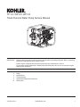
1
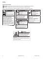
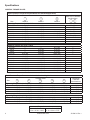
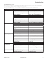
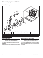
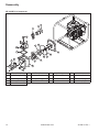
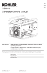
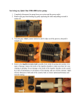
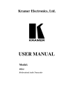
TP 3.0, WP 2.0, WP 3.0
Trash Pump & Water Pump Service Manual
IMPORTANT:
2
3
5
6
10
Read all safety precautions and instructions carefully before operating equipment. Refer to operating
instruction of equipment that this engine powers.
Ensure engine is stopped and level before performing any maintenance or service.
For all engine related maintenance, disassembly and reassembly, refer to service manual of engine
powering this equipment.
Safety
Specifications
Troubleshooting
Disassembly/Inspection and Service
Reassembly
35 690 01 Rev. --
KohlerPower.com
1
Safety
SAFETY PRECAUTIONS
WARNING: A hazard that could result in death, serious injury, or substantial property damage.
CAUTION: A hazard that could result in minor personal injury or property damage.
NOTE: is used to notify people of important installation, operation, or maintenance information.
WARNING
WARNING
Rotating Parts can cause
severe injury.
Stay away while pump is
in operation.
WARNING
Explosive Fuel can
cause fires and severe
burns.
Do not fill fuel tank while
engine is hot or running.
Gasoline is extremely flammable
and its vapors can explode
if ignited. Never refuel while
smoking or in vicinity of an open
flame. Store gasoline only in
approved containers, in well
ventilated, unoccupied buildings,
away from sparks or flames.
Spilled fuel could ignite if it comes
in contact with hot parts or sparks
from ignition. Never use gasoline
as a cleaning agent.
Keep hands, feet, hair, and
clothing away from all moving
parts to prevent injury. Never
operate pump with covers,
shrouds, or guards removed.
CAUTION
Electrical Shock can
cause injury.
Do not touch wires while
engine is running.
Hot Parts can cause
severe burns.
Do not touch engine
while operating or just
after stopping.
Never operate pump with heat
shields or guards removed. Do not
modify pump.
Place pump in a place where
pedestrians or children are not
likely to touch pump.
Be sure to carry pump only by its
carrying handles.
Never operate pump in rain or
snow.
Never touch pump with wet hands
or electrical shock will occur.
WARNING
Carbon Monoxide. Can cause
severe nausea, fainting or death.
Avoid inhaling exhaust fumes.
Only use product outdoors.
Engine exhaust gases contain poisonous carbon
monoxide.
Carbon monoxide is odorless, colorless, and can
cause death if inhaled.
2
KohlerPower.com
35 690 01 Rev. --
Specifications
ENGINE IDENTIFICATION NUMBERS
Kohler portable power products identification numbers (model, specification and serial) should be referenced for
efficient repair, ordering correct parts, and product replacement.
Model . . . . . . . . . . . . . . . . . . . . . TP 3.0
Pump Type (TP or WP)
Port Size (Inch)
Specification . . . . . . . . . . . . . . .
PA-TP30-3001
Serial . . . . . . . . . . . . . . . . . . . . . 4323500328
Year Manufactured Code
Code
Year
43
2013
44
2014
45
2015
GENERAL SPECIFICATIONS3
Overall Dimensions (L x W x H)
Suction and Discharge Size
Dry Weight
Maximum Flow Rate
Maximum Suction Head
Maximum Lift Head
Maximum Debris Size
Factory Code
TP 3.0
WP 2.0
WP 3.0
685 mm (28.2 in.)
615 mm (24.3 in.)
570 mm (22.4 in.)
476 mm (18.8 in.)
540 mm (23.2 in.)
487 mm (19.2 in.)
76 mm (3 in.)
51 mm (2 in.)
76 mm (3 in.)
43.1 kg (95.0 lbs.) 29.9 kg (66.0 lbs.) 34.9 kg (77.0 lbs.)
1,200 l/min.
602 l/min.
1,003 l/min.
(317 gal./min.)
(159 gal./min.)
(265 gal./min.)
8 m (26 ft.)
26 m (85 ft.)
30 m (98 ft.)
28 mm (1.1 in.)
N/A
TORQUE SPECIFICATIONS3
Engine Isolators
M8 Nut
18.3 N·m (162 in. lb.)
Frame/Engine Mounting
M8 Nut
25.5 N·m (226 in. lb.)
Pump Casing Assembly
M8 Screw
M10 Screw
18.5 N·m (164 in. lb.)
22.5 N·m (199 in. lb.)
Pump Casing Assembly
5/16-24 Screw
22.0 N·m (195 in. lb.)
3
Values are in Metric units. Values in parentheses are English equivalents.
35 690 01 Rev. --
KohlerPower.com
3
Specifications
GENERAL TORQUE VALUES
English Fastener Torque Recommendations for Standard Applications
Bolts, Screws, Nuts and Fasteners Assembled Into Cast Iron or Steel
Grade 2 or 5 Fasteners
Into Aluminum
Size
Grade 2
Tightening Torque: N·m (in. lb.) ± 20%
8-32
2.3 (20)
10-24
3.6 (32)
10-32
3.6 (32)
1/4-20
7.9 (70)
1/4-28
9.6 (85)
5/16-18
17.0 (150)
5/16-24
18.7 (165)
3/8-16
29.4 (260)
3/8-24
33.9 (300)
Grade 5
Grade 8
2.8 (25)
4.5 (40)
4.5 (40)
13.0 (115)
15.8 (140)
28.3 (250)
30.5 (270)
—
—
—
—
—
18.7 (165)
22.6 (200)
39.6 (350)
—
—
—
2.3 (20)
3.6 (32)
—
7.9 (70)
—
17.0 (150)
—
—
—
Tightening Torque: N·m (ft. lb.) ± 20%
5/16-24
—
3/8-16
—
3/8-24
—
7/16-14
47.5 (35)
7/16-20
61.0 (45)
1/2-13
67.8 (50)
1/2-20
94.9 (70)
9/16-12
101.7 (75)
9/16-18
135.6 (100)
5/8-11
149.5 (110)
5/8-18
189.8 (140)
3/4-10
199.3 (147)
3/4-16
271.2 (200)
—
47.5 (35)
54.2 (40)
74.6 (55)
101.7 (75)
108.5 (80)
142.4 (105)
169.5 (125)
223.7 (165)
244.1 (180)
311.9 (230)
332.2 (245)
440.7 (325)
40.7 (30)
67.8 (50)
81.4 (60)
108.5 (80)
142.5 (105)
155.9 (115)
223.7 (165)
237.3 (175)
311.9 (230)
352.6 (260)
447.5 (330)
474.6 (350)
637.3 (470)
—
—
—
—
—
—
—
—
—
—
—
—
—
Metric Fastener Torque Recommendations for Standard Applications
Property Class
Size
4.8
5.8
Noncritical
Fasteners
Into Aluminum
8.8
10.9
12.9
Tightening Torque: N·m (in. lb.) ± 10%
M4
1.2 (11)
1.7 (15)
M5
2.5 (22)
3.2 (28)
M6
4.3 (38)
5.7 (50)
M8
10.5 (93)
13.6 (120)
2.9 (26)
5.8 (51)
9.9 (88)
24.4 (216)
4.1 (36)
8.1 (72)
14.0 (124)
33.9 (300)
5.0 (44)
9.7 (86)
16.5 (146)
40.7 (360)
2.0 (18)
4.0 (35)
6.8 (60)
17.0 (150)
Tightening Torque: N·m (ft. lb.) ± 10%
M10
21.7 (16)
27.1 (20)
M12
36.6 (27)
47.5 (35)
M14
58.3 (43)
76.4 (56)
47.5 (35)
82.7 (61)
131.5 (97)
66.4 (49)
116.6 (86)
184.4 (136)
81.4 (60)
139.7 (103)
219.7 (162)
33.9 (25)
61.0 (45)
94.9 (70)
Torque Conversions
N·m = in. lb. x 0.113
in. lb. = N·m x 8.85
N·m = ft. lb. x 1.356
ft. lb. = N·m x 0.737
4
KohlerPower.com
35 690 01 Rev. --
Troubleshooting
TROUBLESHOOTING GUIDE
When troubles occur, be sure to check simple causes which, at first, may seem too obvious to be considered. For
example, a starting problem could be caused by an empty fuel tank.
Some general common causes of pump troubles are listed below. Use these to locate causing factors.
Condition
Pump fails to prime.
Pump primes too slowly.
Reduced capacity or
discharge pressure.
Possible Cause
Pump not filled with liquid.
Add liquid to pump through priming port.
Air leak at suction line connection.
Add sealant to connection.
Worn suction connection gasket.
Replace suction gasket.
Leaking suction line.
Inspect, repair, or replace suction line.
Engine speed too low.
Run engine at maximum speed.
Worn or broken volute or impeller.
Replace parts as required.
Leaking/worn mechanical seal.
Replace mechanical seal.
Clogged suction strainer/line.
Clean strainer and suction line.
Suction lift too great (25 ft. max).
Reduce lift.
Suction line too long.
Reduce length to under 30 feet.
Pump is air locked.
Vent pump discharge through priming port.
Insufficient priming water.
Add more water through pump filler cap.
Mechanical seal chipped or broken.
Replace mechanical seal.
Check valve damaged.
Replace check valve.
Suction hose damaged or strainer
clogged.
Replace hose.
Air leaks caused by O-ring damage.
Clean strainer.
Engine rpm too low.
Replace O-rings.
Lift head too high.
Check rpm and reset throttle as required.
Insufficient priming water.
Lower lift head.
Clogged strainer or lines.
Clean strainer, suction and discharge
lines.
High friction loss in line.
Remove kinks and elbows, reduce length.
Discharge head too high.
Lower end of discharge line, remove
nozzles.
Engine speed too low.
Increase engine speed.
Drop in engine output.
Repair engine.
Clogged impeller.
Remove clog.
Worn/damaged impeller or volute.
Replace parts as required.
Pump will not work/engine Clogged pump.
will not turn over.
Pump parts rusted together.
Remove clog between impeller and volute.
Disassemble pump, free parts.
Damaged impeller or volute.
Replace volute or impeller.
Engine seized.
Remove pump from engine, check engine
itself.
Pump will not work/engine Impeller stripped/key sheared.
runs.
Pump impeller/volute clogged.
Insufficient liquid supply.
35 690 01 Rev. --
Conclusion
KohlerPower.com
Disassemble pump, replace parts/engine.
Clean pump.
Increase liquid supply.
5
Disassembly/Inspection and Service
TP 3.0 Components
P
O
Q
T
L
R
M
S
N
Q
L
P
U
O
H
G
D
B
J
A
I
P
F
K
D
E
C
A
A
Pump Drain Plug
B
Knob Nut
C
Pump Cover
D
O-ring
E
Volute
F
Impeller Cover
G
Impeller
H
Rotating Seal
I
Mechanical Seal
J
Pump Case
K
Eye Bolt
L
Gasket
M
Check Valve
N
Inlet Flange
O
Rubber Seal
P
Hose Joint
Q
Coupling
R
Outlet Flange
S
Discharge Chamber
T
Pump Filler Cap
U
Shims
Remove Outlet Flange
NOTE: Outlet flange position is important. Observe
which way outlet flange faces discharge
chamber for reassembly.
1. Remove outlet flange screws and remove outlet
flange.
Inspection
Inspect gasket for cracks, tears or improper fit. Replace
if necessary.
6
Remove Discharge Chamber
1. Remove discharge chamber screws and lift
discharge chamber off.
2. Remove gasket.
Inspection
Inspect gasket for tears, cracks, or twists. Replace if
necessary.
KohlerPower.com
35 690 01 Rev. --
Disassembly/Inspection and Service
Remove Inlet Flange and Check Valve
NOTE: Check valve position is important. Observe
which way check valve faces inlet flange for
reassembly.
1. Remove inlet flange screws and remove inlet flange.
Inspection
Inspect check valve for tears, cracks, or twists. Replace
if necessary.
Remove Pump Cover and Volute
NOTE: Pump cover and volute are heavy; be prepared
to handle weight to maneuver for inspection and
service.
1. Drain any water from reservoir by loosening drain
plug. Loosen knob nuts that hold pump cover to
pump case. Use special wrench provided with pump.
2. Push knobs to side and remove pump cover from
pump case.
Inspection
Inspect volute, impeller cover and pump cover for cracks
or bent castings. Also inspect impeller cover for uneven
wear marks.
NOTE: Volute position is important. Observe which way
volute discharge faces pump cover for
reassembly.
1. Remove Allen head screws holding volute to pump
cover.
2. Tap with a rubber mallet to free volute from pump
cover.
3. Carefully remove volute from housing by pulling up.
4. Check volute O-ring sealing volute to pump cover.
Check for nicks, cracks, and tearing. Replace if
necessary.
5. Remove screws that hold impeller cover to volute.
Remove impeller cover.
6. Check condition of pump cover O-ring. Check for
nicks, tears and gouging.
7. Install impeller cover with screws and washers.
8. Apply Loctite® 587™ Ultra Blue or equivalent to
impeller cover screws before tightening.
9. Torque impeller cover screws to 18.5 N·m
(164 in. lbs.).
10. Position volute back onto pump cover with screws
and washers.
11. Apply Loctite® 587™ Ultra Blue or equivalent to
screws before installing.
12. Torque screws to 18.5 N·m (164 in. lbs.).
13. Volute and pump cover are now ready to be installed
onto pump case.
35 690 01 Rev. --
Remove Impeller
NOTE: Impeller is heavy.
1. Remove pump drain plug on pump case for access
to impeller. Insert a soft rod, such as aluminum or
brass, through pump drain plug hole and position rod
against impeller. Using a hammer, hit rod to loosen
impeller.
2. Turn impeller counter-clockwise by hand until free
from crankshaft. Be prepared to catch impeller when
free from crankshaft.
3. Inspect impeller for cracks and bent blades.
4. Count number of shim(s) that are located on end of
crankshaft. Remove slowly and make sure to
replace with same number when reassembling.
5. Shim(s) may get stuck in impeller. Use a screwdriver
to pry out and inspect. Shim should not be bent or
distorted in any way. Replace if necessary.
6. Turn impeller over and remove rotating seal with a
small screwdriver. Pry on bottom side and lift upward
until removed from impeller.
7. There is a wrong side to rotating seal. Colored
marks will face inward (or towards inlet nozzle side
of pump).
Inspection
Inspect condition of volute to pump case O-ring. Check
for cracks, nicks or tears. Replace if necessary.
Remove Mechanical Seal
NOTE: Drops of dish washing soap on shaft will help
remove mechanical seal. This prevents sealing
lip from possibly tearing when removing.
NOTE: If pump case needs to be removed to remove
mechanical seal, follow Remove Pump Case
directions then remove mechanical seal.
1. Using two screwdrivers, remove mechanical seal by
prying side to side until it is free. It may be
necessary to remove pump case to remove
mechanical seal.
2. Pull seal off crankshaft and inspect for cracks, burn
marks and overall condition. Replace if necessary.
Remove Pump Case
1. Remove screws securing pump case to engine.
These are special screws with special washers.
Make sure to replace with same part numbers if
needed.
2. Loosen screws that hold pump case to frame and
prepare to tilt engine back slightly for removal of
pump case.
3. Lift engine and pump case high enough to clear
screws from frame mounts.
4. Pull pump case from engine. It may become
necessary to tap of pump case slightly with a rubber
mallet.
5. Should it become necessary to remove engine for
service, then remove screws that hold it to engine
vibration mounts.
KohlerPower.com
7
Disassembly/Inspection and Service
WP 2.0/WP 3.0 Components
O
N
P
M
H
L
Q
K
G
C
E
J
I
C
F
D
B
A
A
Pump Drain Plug
B
Pump Cover
C
O-ring
D
Volute
E
Rotating Seal
F
Mechanical Seal
G
Pump Case
H
Impeller
I
Check Valve
J
Inlet Flange
K
Gasket
L
Outlet Flange
M
Pump Filler Cap
N
Rubber Seal
O
Hose Joint
P
Coupling
Q
Shims
Remove Outlet Flange
NOTE: Outlet flange position is important. Observe
which way outlet flange faces discharge
chamber for reassembly.
1. Remove outlet flange screws and remove outlet
flange.
Inspection
Inspect gasket for cracks, tears or improper fit. Replace
if necessary.
8
Remove Inlet Flange and Check Valve
NOTE: Check valve position is important. Observe
which way check valve faces inlet flange for
reassembly.
1. Remove inlet flange screws and remove inlet flange.
Inspection
Inspect check valve for tears, cracks, or twists. Replace
if necessary.
KohlerPower.com
35 690 01 Rev. --
Disassembly/Inspection and Service
Remove Pump Cover and Volute
NOTE: Pump cover and volute are heavy; be prepared
to handle weight to maneuver for inspection and
service.
NOTE: Volute is not secured to pump cover. Take care
when handling pump cover and volute.
1. Drain any water from reservoir by loosening drain
plug. Loosen screws that hold pump cover to pump
case.
Inspection
Inspect volute and pump cover for cracks or bent
castings.
NOTE: Volute position is important. Observe tab on
volute matches notch in pump cover for
reassembly.
1. Carefully remove volute from housing by pulling up.
2. Check volute O-ring sealing volute to pump cover.
Check for nicks, cracks, and tearing. Replace if
necessary.
Remove Impeller
NOTE: Impeller is heavy.
1. Using a rubber mallet, hit a blade to loosen impeller.
2. Turn impeller counter-clockwise by hand until free
from crankshaft. Be prepared to catch impeller when
free from crankshaft.
3. Inspect impeller for cracks and bent blades.
4. Count number of shim(s) that are located on
crankshaft. Remove slowly and make sure to
replace with same number when reassembling.
5. Shim(s) may get stuck in impeller. Use a screwdriver
to pry out and inspect. Shim should not be bent or
distorted in any way. Replace if necessary.
6. Turn impeller over and remove rotating seal with a
small screwdriver. Pry on bottom side and lift upward
until removed from impeller.
7. There is a wrong side to rotating seal. Colored
marks will face inward (or towards inlet nozzle side
of pump).
35 690 01 Rev. --
Inspection
Inspect condition of volute to pump case O-ring. Check
for cracks, nicks or tears. Replace if necessary.
Remove Mechanical Seal
NOTE: Drops of dish washing soap on shaft will help
remove mechanical seal. This prevents sealing
lip from possibly tearing when removing.
NOTE: If pump case needs to be removed to remove
mechanical seal, follow Remove Pump Case
directions then remove mechanical seal.
1. Using two screwdrivers, remove mechanical seal by
prying side to side until it is free. It may be
necessary to remove pump case to remove
mechanical seal.
2. Pull seal off crankshaft and inspect for cracks, burn
marks and overall condition. Replace if necessary.
Remove Pump Case
1. Remove screws securing pump case to engine.
These are special screws with special washers.
Make sure to replace with same part numbers if
needed.
2. Loosen screws that hold pump case to frame and
prepare to tilt engine back slightly for removal of
pump case.
3. Lift engine and pump case high enough to clear
screws from frame mounts.
4. Pull pump case from engine. It may become
necessary to tap of pump case slightly with a rubber
mallet.
5. Should it become necessary to remove engine for
service, then remove screws that hold it to engine
vibration mounts.
Inspection
Check condition of pump cover O-ring. Check for nicks,
tears and gouging.
KohlerPower.com
9
Reassembly
TP 3.0 Components
P
O
Q
T
L
R
M
S
N
Q
L
P
U
O
H
G
D
B
J
A
I
P
F
K
D
E
C
A
A
Pump Drain Plug
B
Knob Nut
C
Pump Cover
D
O-ring
E
Volute
F
Impeller Cover
G
Impeller
H
Rotating Seal
I
Mechanical Seal
J
Pump Case
K
Eye Bolt
L
Gasket
M
Check Valve
N
Inlet Flange
O
Rubber Seal
P
Hose Joint
Q
Coupling
R
Outlet Flange
S
Discharge Chamber
T
Pump Filler Cap
U
Shims
10
KohlerPower.com
35 690 01 Rev. --
Reassembly
Install Pump Case
NOTE: When replacing pump case on engine, note
weep hole on backside of pump case. Weep
hole must not be blocked with dirt or other
obstruction. This weep hole prevents water from
entering engine should mechanical seal fail
while pumping water.
1. Apply Loctite® 587™ Ultra Blue or equivalent to
screws.
2. Replace pump case and hold in position.
3. Secure with screws and washers.
4. Torque pump case screws to 22.5 N·m (199 in. lbs.).
Install Pump Cover
1. Install pump cover to pump case and loosely tighten
knob nuts making sure O-ring is seated correctly.
2. Tighten knob nuts with special tool that is provided
with pump. Tighten very snugly.
Install Mechanical Seal
NOTE: Drops of dish washing soap on shaft will help
install mechanical seal.
NOTE: If pump case was removed it will be easier to
install mechanical seal before mounting pump
case to engine.
1. Using thumbs, push mechanical seal into place.
Install Discharge Chamber
1. Install discharge chamber and gasket with screws
and washers. Torque screws to 18.5 N·m
(164 in. lbs.).
Install Impeller
NOTE: Before placing rotating seal into impeller it will
help to put some liquid detergent on seal. This
will ease installation.
1. Replace shim(s). As noted earlier it will be necessary
to replace with same amount that was taken off.
2. Install rotating seal into backside of impeller making
sure rotating seal is not kinked and placed on
straight.
3. Turn impeller on by hand in a clockwise position until
tight.
4. Hit 1 blade in a clockwise position to tighten impeller
until resistance is observed.
35 690 01 Rev. --
Install Inlet Flange and Check Valve
1. Apply Loctite® 587™ Ultra Blue or equivalent to inlet
flange screws.
2. Install inlet flange and check valve to pump cover
with screws and washers. Torque screws to
18.5 N·m (164 in. lbs.).
Install Outlet Flange
1. Apply Loctite® 5770™ High Temperature Thread
Sealant or equivalent to screws
2. Install outlet flange and rubber gasket with screws
and washers.
3. Torque screws to 18.5 N·m (164 in. lbs.).
Testing Pump
1. Before running check oil and pull engine over with
retractable starter to make sure nothing is binding in
pump.
2. Fill with prime water, start engine. After warm up run
engine at full throttle and check vacuum with
vacuum tester to make sure no leaks have
developed. A vacuum of 20 to 25 lbs at sea level
should be read. This reading should be obtained
within 5 seconds.
KohlerPower.com
11
Reassembly
WP 2.0/WP 3.0 Components
O
N
P
M
H
L
Q
K
G
C
E
J
I
C
F
D
B
A
A
Pump Drain Plug
B
Pump Cover
C
O-ring
D
Volute
E
Rotating Seal
F
Mechanical Seal
G
Pump Case
H
Impeller
I
Check Valve
J
Inlet Flange
K
Gasket
L
Outlet Flange
M
Pump Filler Cap
N
Rubber Seal
O
Hose Joint
P
Coupling
Q
Shims
12
KohlerPower.com
35 690 01 Rev. --
Reassembly
Install Pump Case
NOTE: When replacing pump case on engine, note
weep hole on backside of pump case. Weep
hole must not be blocked with dirt or other
obstruction. This weep hole prevents water from
entering engine should mechanical seal fail
while pumping water.
1. Apply Loctite® 587™ Ultra Blue or equivalent to
screws.
2. Replace pump case and hold in position.
3. Secure with screws and washers.
4. Torque pump case screws to 22.5 N·m (199 in. lbs.).
Install Mechanical Seal
NOTE: Drops of liquid detergent on shaft will help install
mechanical seal.
NOTE: If pump case was removed it will be easier to
install mechanical seal before mounting pump
case to engine.
1. Using thumbs, push mechanical seal into place.
Install Impeller
NOTE: Before placing rotating seal into impeller it will
help to put some liquid detergent on seal. This
will ease installation.
1. Replace shim(s). As noted earlier it will be necessary
to replace with same amount that was taken off.
2. Install rotating seal into backside of impeller making
sure rotating seal is not kinked and placed on
straight.
3. Turn impeller on by hand in a clockwise position until
tight.
4. Hit 1 blade in a clockwise position to tighten impeller
until resistance is observed.
5. Place volute against pump case and check
clearance between volute and impeller with a feeler
gauge. A clearance larger than 1.2 mm (0.0472)
requires another shim. A clearance of less than
0.4 mm (0.0157 in.) requires removal of a shim. If a
shim is added or removed, repeat steps 3, 4 and 5.
6. Remove volute.
35 690 01 Rev. --
Install Pump Cover
1. Install volute into pump cover, aligning volute tab
and pump case notch.
1. Install pump cover to pump case and loosely tighten
screws making sure O-ring is seated correctly.
2. Torque pump cover screws to 18.5 N·m
(164 in. lbs.).
Install Inlet Flange and Check Valve
1. Apply Loctite® 587™ Ultra Blue or equivalent to inlet
flange screws.
2. Install inlet flange and check valve to pump cover
with screws and washers. Torque screws to
18.5 N·m (164 in. lbs.).
Install Outlet Flange
1. Apply Loctite® 5770™ High Temperature Thread
Sealant or equivalent to screws
2. Install outlet flange and rubber gasket with screws
and washers.
3. Torque screws to 18.5 N·m (164 in. lbs.).
Testing Pump
1. Before running check oil and pull engine over with
retractable starter to make sure nothing is binding in
pump.
2. Fill with prime water, start engine. After warm up run
engine at full throttle and check vacuum with
vacuum tester to make sure no leaks have
developed. A vacuum of 20 to 25 lbs at sea level
should be read. This reading should be obtained
within 5 seconds.
KohlerPower.com
13
14
KohlerPower.com
35 690 01 Rev. --
35 690 01 Rev. --
KohlerPower.com
15
© 2013 by Kohler Co. All rights reserved.
16
KohlerPower.com
35 690 01 Rev. --