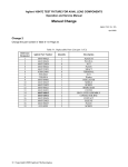
1
Caution
Proper handling care should be taken when using the test fixture.
Refrain from applying brute force, doing so could damage the fixture.
Particularly the upper portion (where the DUT is mounted) of the
test fixture, where all the sensitive parts have been accurately set and
adjusted. Do not place the test fixture on top of a desk or any hard
objects with its face down (reverse).
注意
破損する可能性がありますので、本器に衝撃を与えないように、取扱いには
注意してください。特に上面(試料を載せる面)側は、部品位置が精密に調
注意してください。特に上面
(試料を載せる面)側は、部品位置が精密に調
整されており、細かな部品も使用されておりますので、絶対に衝撃を与えな
いで下さい。例えば、上面側を下にして、机などの硬い物の上に置かないで
下さい。
Agilent 16047E Test Fixture
Operation and Service Manual
Third Edition
Agilemt Part No. 16047-90040
January 2001
Printed in: Japan
Notices
The information contained in this document is subject to change without notice.
This document contains proprietary information that is protected by copyright.All
rights are reserved. No part of this document may be photocopied, reproduced, or
translated to another language without the prior written consent of the Agilent
Technologies.
Agilent Technologies Japan, Ltd.
Component Test PGU-Kobe
1-3-2, Murotani, Nishi-Ku, Kobe-shi, Hyogo, 651-2241 Japan
© Copyright Agilent Technologies Japan, Ltd. 1999, 2001
Manual Printing History
The manual’s printing date and part number indicate its current edition. The
printing date changes when a new edition is printed. (Minor corrections and
updates that are incorporated at reprint do not cause the date to change.) The
manual part number changes when extensive technical changes are incorporated.
April 1999
First Edition (part number: 16047-90040)
December 1999
Second Edition (part number: 16047-90040)
January 2001
Third Edition (part number: 16047-90040)
Safety Summary
The following general safety precautions must be observed during all phases of
operation, service, and repair of this instrument. Failure to comply with these
precautions or with specific WARNINGS elsewhere in this manual may impair the
protection provided by the equipment. In addition it violates safety standards of
design, manufacture, and intended use of the instrument.
The Agilent Technologies assumes no liability for the customer’s failure to comply
with these requirements.
•
2
DO NOT Operate In An Explosive Atmosphere
Do not operate the instrument in the presence of flammable gasses or fumes.
Operation of any electrical instrument in such an environment constitutes a
definite safety hazard.
•
Keep Away From Live Circuits
Operating personnel must not remove instrument covers. Component
replacement and internal adjustments must be made by qualified maintenance
personnel. Do not replace components with the power cable connected. Under
certain conditions, dangerous voltages may exist even with the power cable
removed. To avoid injuries, always disconnect power and discharge circuits
before touching them.
•
DO NOT Service Or Adjust Alone
Do not attempt internal service or adjustment unless another person, capable of
rendering first aid and resuscitation, is present.
•
DO NOT Substitute Parts Or Modify Instrument
Because of the danger of introducing additional hazards, do not install
substitute parts or perform unauthorized modifications to the instrument.
Return the instrument to a Agilent Technologies Sales and Service Office for
service and repair to ensure that safety features are maintained.
•
Dangerous Procedure Warnings
Warnings, such as the example below, precede potentially dangerous
procedures throughout this manual. Instructions contained in the warnings must
be followed.
WARNING
Dangerous voltages, capable of causing death, are presenting this instrument.
Use extreme caution when handling, testing, and adjusting this instrument.
Certification
Agilent Technologies certifies that this product met its published specifications at
the time of shipment from the factory. Agilent Technologies further certifies that
its calibration measurements are traceable to the United States National Institute of
Standards and Technology, to the extent allowed by the Institution’s calibration
facility, or to the calibration facilities of other International Standards Organization
members.
3
Warranty
This Agilent Technologies instrument product is warranted against defects in
material and workmanship for a period corresponding to the individual warranty
periods of its component products. Instruments are warranted for a period of one
year. Fixtures and adapters are warranted for a period of 90 days. During the
warranty period, Agilent Technologies will, at its option, either repair or replace
products that prove to be defective.
For warranty service or repair, this product must be returned to a service facility
designated by Agilent Technologies. Buyer shall prepay shipping charges to
Agilent Technologies and Agilent Technologies shall pay shipping charges to
return the product to Buyer. However, Buyer shall pay all shipping charges, duties,
and taxes for products returned to Agilent Technologies from another country.
Agilent Technologies warrants that its software and firmware designated by
Agilent Technologies for use with an instrument will execute its programming
instruction when property installed on that instrument. Agilent Technologies does
not warrant that the operation of the instrument, or software, or firmware will be
uninterrupted or error free.
Limitation Of Warranty
The foregoing warranty shall not apply to defects resulting from improper or
inadequate maintenance by Buyer, Buyer-supplied software or interfacing,
unauthorized modification or misuse, operation outside the environmental
specifications for the product, or improper site preparation or maintenance.
IMPORTANT
No other warranty is expressed or implied. Agilent Technologies specifically
disclaims the implied warranties of merchantability and fitness for a particular
purpose.
Exclusive Remedies
The remedies provided herein are buyer’s sole and exclusive remedies. Agilent
Technologies shall not be liable for any direct, indirect, special, incidental, or
consequential damages, whether based on contract, tort, or any other legal theory.
4
Assistance
Product maintenance agreements and other customer assistance agreements are
available for Agilent Technologies products.
For any assistance, contact your nearest Agilent Technologies Sales and Service
Office. Addresses are provided at the back of this manual.
Safety Symbol
General definitions of safety symbols used on the instrument or in manuals are
listed below.
Instruction Manual symbol: the product is marked with this symbol when it is
necessary for the user to refer to the instrument manual.
Alternating current.
Direct current.
On (Supply).
Off (Supply).
In position of push-button switch.
Out position of push-button switch.
Frame (or chassis) terminal. A connection to the frame (chassis) of the equipment
which normally include all exposed metal structure.
WARNING
This warning sign denotes a hazard. It calls attention to a procedure, practice,
condition or the like, which, if not correctly performed or adhered to, could
result in injury or death to personnel.
CAUTION
This Caution sign denotes a hazard. It calls attention to a procedure, practice,
condition or the like, which, if not correctly performed or adhered to, could result
in damage to or destruction of part or all of the product.
NOTE
Note denotes important information. It calls attention to a procedure, practice,
condition or the like, which is essential to highlight.
5
6
Contents
1. Installation Guide
Incoming Inspection . . . . . . . . . . . . . . . . . . . . . . . . . . . . . . . . . . . . . . . . . . . . . . . . . . . . . . . . . . . . . . . . . . . 10
Connecting the 16047E. . . . . . . . . . . . . . . . . . . . . . . . . . . . . . . . . . . . . . . . . . . . . . . . . . . . . . . . . . . . . . . . . 11
Connecting to the 4294A. . . . . . . . . . . . . . . . . . . . . . . . . . . . . . . . . . . . . . . . . . . . . . . . . . . . . . . . . . . . . . 11
Connecting to the instrument other than 4294A . . . . . . . . . . . . . . . . . . . . . . . . . . . . . . . . . . . . . . . . . . . . 12
Cleaning . . . . . . . . . . . . . . . . . . . . . . . . . . . . . . . . . . . . . . . . . . . . . . . . . . . . . . . . . . . . . . . . . . . . . . . . . . . . 13
2. Overview
Product Overview . . . . . . . . . . . . . . . . . . . . . . . . . . . . . . . . . . . . . . . . . . . . . . . . . . . . . . . . . . . . . . . . . . . . . 16
Functions. . . . . . . . . . . . . . . . . . . . . . . . . . . . . . . . . . . . . . . . . . . . . . . . . . . . . . . . . . . . . . . . . . . . . . . . . . . . 17
3. Operation
Performing Fixture Compensation . . . . . . . . . . . . . . . . . . . . . . . . . . . . . . . . . . . . . . . . . . . . . . . . . . . . . . . . 20
Performing Open Compensation. . . . . . . . . . . . . . . . . . . . . . . . . . . . . . . . . . . . . . . . . . . . . . . . . . . . . . . . 20
Performing Short Compensation. . . . . . . . . . . . . . . . . . . . . . . . . . . . . . . . . . . . . . . . . . . . . . . . . . . . . . . . 20
Performing Load Compensation . . . . . . . . . . . . . . . . . . . . . . . . . . . . . . . . . . . . . . . . . . . . . . . . . . . . . . . . 21
DUT Measurement . . . . . . . . . . . . . . . . . . . . . . . . . . . . . . . . . . . . . . . . . . . . . . . . . . . . . . . . . . . . . . . . . . . . 22
Measuring 3-terminal device . . . . . . . . . . . . . . . . . . . . . . . . . . . . . . . . . . . . . . . . . . . . . . . . . . . . . . . . . . . . 23
4.
Specifications and Supplemental Performance Characteristics
Specifications . . . . . . . . . . . . . . . . . . . . . . . . . . . . . . . . . . . . . . . . . . . . . . . . . . . . . . . . . . . . . . . . . . . . . . . . 26
Supplemental Performance Characteristics . . . . . . . . . . . . . . . . . . . . . . . . . . . . . . . . . . . . . . . . . . . . . . . . . 27
Additional Error . . . . . . . . . . . . . . . . . . . . . . . . . . . . . . . . . . . . . . . . . . . . . . . . . . . . . . . . . . . . . . . . . . . . 27
5. Service
Maintenance . . . . . . . . . . . . . . . . . . . . . . . . . . . . . . . . . . . . . . . . . . . . . . . . . . . . . . . . . . . . . . . . . . . . . . . . . 32
Replacable Parts . . . . . . . . . . . . . . . . . . . . . . . . . . . . . . . . . . . . . . . . . . . . . . . . . . . . . . . . . . . . . . . . . . . . 32
7
Contents
8
1
Installation Guide
9
Installation Guide
Incoming Inspection
Incoming Inspection
Inspect the shipping container for damage. If the shipping container or cushioning
material is damaged, it should be kept until the contents of the shipment have been
checked for completeness and the 16047E has been checked mechanically and
electrically. The contents of the shipment should be as listed in Table 1-1. If the
contents are incomplete, if there is mechanical damage or defect, notify the nearest
Agilent Technologies office. If the shipping container is damaged, or the
cushioning material shows signs of unusual stress, notify the carrier as well as the
Agilent Technologies office. Keep the shipping materials for the carrier’s
inspection.
Table 1-1
Contents
Description
Part Number
Qty.
16047E Test Fixture
-
1
Shorting bara
16047-00621
1
Operation and Service Manual
16047-90040
1
a. Fasten the guard terminal of the test fixture.
10
Chapter 1
Installation Guide
Connecting the 16047E
Connecting the 16047E
Connecting to the 4294A
Follow these steps below to connect the 16047E to the 4294A.
Step 1. Set the 16047E test fixture to the test connectors on the front panel of the 4294A
by gradually coupling the four BNC connectors and fastening screws of the fixture
with the test connectors and accessory mounting holes of the instrument until they
come to complete contact.
Step 2. Fasten two of the four BNC connectors to the mating test connectors by gradually
turning the two BNC connectors’ rotation levers until each pair of connectors are
securely connected.Be sure to align the grooves on both sides.
Step 3. Turn clockwise the fixture’s two fastening screws together, so that the fixture is
secured to the instrument.
Step 4. Finally, secure the remaining two BNC connectors of the fixture by turning
clockwise their rotation levers.
Figure 1-1
Connecting 16047E to 4294A
NOTE
The fastening screws are designed to provide the fixture with mechanical stability
and a prolonged life. Removing these screws will not affect measurement values.
Chapter 1
11
Installation Guide
Connecting the 16047E
Connecting to the instrument other than 4294A
When connecting the 16047E to any instrument other than the 4294A, remove the
four fastening screws as shown in Figure 1-2.
Figure 1-2
Locations of fastening screws
Step 1. Set the 16047E test fixture to the UNKNOWN connectors on the instrument by
gradually coupling the four BNC connectors and fastening screws of the fixture
with the connectors of the instrument until they come to complete contact. Be sure
to align the grooves on both sides.
Step 2. Secure the two BNC connectors of the fixture by turning clockwise their rotation
levers.
Figure 1-3
Connecting the fixture to the instrument
12
Chapter 1
Installation Guide
Cleaning
Cleaning
When the electrodes get dirty, their contact resistance increases resulting in
inaccurate measurement. Use soft cloth to clean the electrode to remove dust
particles or any other dirt.
Chapter 1
13
Installation Guide
Cleaning
14
Chapter 1
2
Overview
15
Overview
Product Overview
Product Overview
The 16047E is a test fixture used to measure parts with leads. When used with the 4294A,
the fixture provides highly accurate measurement with wide frequency range up to 110
MHz. Also it gains mechanical stability and a prolonged life when it is secured to the
4294A with its fastening screws.
Figure 2-1
Product Overview
16
Chapter 2
Overview
Functions
Functions
Figure 2-2 shows name of each part of the 16047E and Table 2-2 shows function.
Figure 2-2
16047E Parts
Table 2-1
16047E Function
No.
NAME
FUNCTION
1
Electrode
Contact for DUT electrode. The LOW side electrode
connected to an instrument’s LCUR, LPOT and the
HIGH side electrode connected to an instrument’s
HCUR, HPOT.
2
Electrode securing
screws
Secures the electrodes with DUT leads caught.
3
Fixture fastening
screws
Secures the fixture to an instrument.
4
Shorting bar
Detached and used as a shorting bar when
performing short correction. Also used as a guard
terminal securing plate when measuring a 3-terminal
device.
Chapter 2
17
Overview
Functions
18
Chapter 2
3
Operation
This chapter describes the proper methods for fixture compensation with the
16047E and DUT measurement.
19
Operation
Performing Fixture Compensation
Performing Fixture Compensation
To enhance measurement accuracy, fixture compensation should be done before
DUT measurement. The fixture compensation requires measurements with the
16047E for open and short compensation data. The following procedure shows the
measurement for the compensation data.
Performing Open Compensation
The open compensation procedure is as follows.
1. Fasten the electrode securing screws at the HIGH and LOW sides with no DUT
leads caught in the electrodes.
NOTE
Do not fasten the screws too tightly to prevent the electrodes from damaged.
2. Follow the instruction manual that came with your instrument to perform a
measurement to obtain open compensation data.
Performing Short Compensation
The short compensation procedure is as follows.
1. Remove the shorting bar secured on the guard terminal.
2. Loosen the electrode securing screws so that the shorting bar is caught in the
electrodes.
NOTE
Place the shorting bar in the proper direction so that it does not contact to the guard
terminal.
20
Chapter 3
Operation
Performing Fixture Compensation
Figure 3-1
Performing short compensation
3. Fasten the electrode securing screws.
NOTE
Do not fasten the screws too tightly to prevent the electrodes from damaged.
4. Follow the instruction manual that came with your instrument to perform a
measurement to obtain short compensation data.
Performing Load Compensation
Generally, there is no need to perform load compensation. If you have any
standard device or you need to keep consistency in measured data, perform load
compensation.
The load compensation procedure is as follows.
1. Fasten the electrode securing screws at the HIGH and LOW sides with load
leads caught in the electrodes.
NOTE
Do not fasten the screws too tightly to prevent the electrodes from damaged.
2. Follow the instruction manual that came with your instrument to perform a
measurement to obtain load compensation data.
Chapter 3
21
Operation
DUT Measurement
DUT Measurement
Before performing DUT measurement, open and short compensation should be
done as described in the previous sections.
1. Loosen the electrode securing screws of both sides so that DUT leads are
caught in the electrodes.
2. Fasten both of the securing screws.
NOTE
Figure 3-2
Do not fasten the screws too tightly to prevent the electrodes from damaged.
Performing DUT Measurement
3. Follow the instruction manual that came with your instrument to measure your
DUT.
22
Chapter 3
Operation
Measuring 3-terminal device
Measuring 3-terminal device
The 16047E allows you to measure a 3-terminal device shown in Figure 3-3.
Figure 3-3
3-terminal device
Use the guard terminal on the fixture to measure a 3-terminal device.Connect the
lead No. 3 to the guard terminal in order to measure only characteristics of Z1
eliminating any effects from Z2 and Z3.
1. Loosen the electrode securing screws of both sides and the screw of the guard
terminal.
2. Insert the leads No. 1 or 2 into the electrodes, then fasten the screws. Insert the
lead No. 3 into the guard terminal, then secure it with the screw.
Figure 3-4
Measuring 3-terminal device
3. Follow the instruction manual that came with your instrument to measure your
Chapter 3
23
Operation
Measuring 3-terminal device
DUT.
Similarly, connect the lead No. 2 to the guard terminal in order to measure only
characteristics of Z2 eliminating any effects from Z1 and Z3.
NOTE
Connect your device to the guard terminal with a shortest possible lead. Longer
lead will degrade the guard effect resulting in less accurate measurement result.
24
Chapter 3
4
Specifications and Supplemental
Performance Characteristics
This chapter provides specifications and supplemental performance characteristics
of the 16047E test fixture.
25
Specifications and Supplemental Performance Characteristics
Specifications
Specifications
Applicable Instruments
LCR meters and Impedance Analyzers with
four-terminals
Applicable DUT Type
Lead components
Frequency
≤ 110MHz
DC Bias
± 42V peak max. (AC+DC)
Operating
Environment
temp.
-20°C to +75°C
humidity
15% to 95%RH( @ wet bulb temp. < 40°C)
Non Operating
temp.
-40°C to +70°C
Environment.
humidity
≤ 90 % RH ( @ wet bulb temp. <65°C)
Dimension
Approximately 135 (W) × 40 (H) × 65 (D) mm
Weight
Approximately 200g
26
Chapter 4
Specifications and Supplemental Performance Characteristics
Supplemental Performance Characteristics
Supplemental Performance Characteristics
This section provides useful data on the 16047E. These supplemental performance
characteristics should not be considered specifications.
Additional Error
Additional errors are calculated as follows.
|Z| Measurement
Additional error Ze [%] of the |Z| measurement is calculated by substituting the
values in the table below into the following equation.
Ze [%] = ± {A + (Zs/Zx + Yo ×Zx) × 100}
where
A [%]
Additional Error (Proportional Error)
Yo [S]
Open Repeatability (Admittance)
Zs [Ω]
Short Repeatability (Impedance)
Zx [Ω]
Measured Value (Impedance)
Without extension cable
Applicable Instruments : 4294A
Yo
2 n + 10 µ × ( f / 100 ) [S]
Zs
2 m + 600 m × ( f / 100 ) [Ω]
A
f ≤ 15 MHz
0.2 % × ( f / 10 )2 [%]
f > 15MHz
4 % × ( f / 100 ) [%]
where f is the measurement frequency (MHz).
Without extension cable
Applicable Instruments : 4192A, 4194A, 4263B, 4268A, 4278A, 4279A, 4284A,
4285A, 4338B
Yo
2 n + 10 µ × ( f / 100 ) [S]
Zs
2 m + 600 m × ( f / 100 ) [Ω]
A
0.2 % × ( f / 10 )2 [%]
where f is the measurement frequency (MHz).
Chapter 4
27
Specifications and Supplemental Performance Characteristics
Supplemental Performance Characteristics
4194A (extension cable 1m)
Yo
4 n + 20 µ × ( f / 100 ) [S]
Zs
4 m + 1200 m × ( f / 100 ) [Ω]
A
0.6 % × ( f / 10 )2 [%]
where f is the measurement frequency (MHz).
4285A, 4294A (extension cable 1m)
Yo
4 n + 20 µ × ( f / 100 ) [S]
Zs
4 m + 1200 m × ( f / 100 ) [Ω]
A
f ≤ 5 MHz
0.6 % × ( f / 10 )2 [%]
f > 5MHz
8 % × ( f / 100 ) [%]
where f is the measurement frequency (MHz).
4285A, 4294A (extension cable 2m)
Yo
4 n + 20 µ × ( f / 100 ) [S]
Zs
4 m + 1200 m × ( f / 100 ) [Ω]
A
f ≤ 5 MHz
1 % × ( f / 10 )2 [%]
f > 5MHz
8 % × ( f / 100 ) [%]
where f is the measurement frequency (MHz).
D Measurement
Additional error De of the D measurement is calculated by additional error Ze [%]
of |Z| measurement as follows.
If Dx ≤ 0.1:
De = Ze / 100
If 0.1 < Dx ≤ 0.5:
De = ( Ze / 100) × (1 + Dx)
where Dx is the measured value of D. It is necessary for Ze to be below 10 %.
NOTE
D is not expressed as a percentage but as an absolute value.
28
Chapter 4
Specifications and Supplemental Performance Characteristics
Supplemental Performance Characteristics
Rs (ESR) Measurement
Additional error Rse[%] of the Rs measurement is calculated by additional error
Ze [%] of |Z| measurement as follows.
If Dx ≤ 0.1:
Rse [%] = Ze / Dx
If 0.1 < Dx ≤ 0.5:
2
Rse [%] = ( Ze / Dx) × ( 1 + Dx )
Dx is the measured value of D and is calculated as follows.
Dx = 2 × π × f × Csx × Rsx,
where
f: measurement signal frequency
Csx: measured value of Cs
Rsx: measured value of Rs.
Chapter 4
29
Specifications and Supplemental Performance Characteristics
Supplemental Performance Characteristics
30
Chapter 4
5
Service
This chapter provides information on servicing and proper maintenance.
31
Service
Maintenance
Maintenance
An exploded view of the 16047E for parts identification is shown in Figure 5-1 and
Figure 5-2. Do not disassemble any further than shown. Maintenance consists
principally of cleaning contacts and replacing worn or damaged parts. Take special
care when cleaning contacts.
To order parts, use the Agilent Technologies part numbers listed in Table 1-1 and
Table 1-2. If a faulty part is located in an assembly that cannot be disassembled,
order the next higher assembly or return the fixture to the nearest Agilent
Technologies Sales/Service Office for repair or replacement.
Replacable Parts
Figure 5-1
Replacable Parts (part 1 of 2)
32
Chapter 5
Service
Maintenance
Table 5-1
Replacable Parts (part 1 of 2)
Reference
Designator
Agilent Part No.
Qty.
Description
1
16047-00623
1
PLATE-H
2
16047-00624
1
PLATE-L
3
16047-24024
4
NUT
4
16047-00622
2
PLATE
5
16047-23021
2
SHAFT
6
16380-24001
4
TERMINAL
7
2950-0043
4
NUT
8
2190-0016
2
Washer
9
16047-09001
1
INSULATOR
10
16047-00625
1
SHIELD
11
16047-24022
1
SCREW
12
16047-00621
1
SHORT BAR
13
16047-04021
1
COVER
14
16047-60011
2
BNC LEVER ASSEMBLY
15
1250-1798
2
CONNECTOR-BNC
16
16047-00626
1
CONTACT
17
16047-24023
2
SLEEVE
18
16047-00627
1
PLATE
19
0515-0999
2
SCREW
Chapter 5
33
Service
Maintenance
Figure 5-2
Replacable Parts (part 2 of 2)
34
Chapter 5
Service
Maintenance
Table 5-2
Replacable Parts (part 2 of 2)
Reference
Designator
Agilent Part No.
Qty.
Description
1
0370-2446
2
KNOB
2
16047-04022
1
COVER
3
16047-24021
2
KNOB
4
16047-24026
2
FLANGE
5
0515-0914
4
SCREW
6
16047-01222
1
ANGLE
7
0515-0952
4
SCREW
8
0515-0999
3
SCREW
9
16047-25021
2
INSULATER
10
0515-2791
1
SCREW
11
16047-24025
1
SLEEVE
12
0515-0914
2
SCREW
13
16047-01221
1
ANGLE
Chapter 5
35
Service
Maintenance
36
Chapter 5