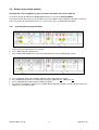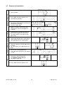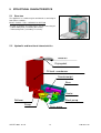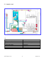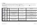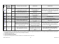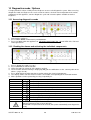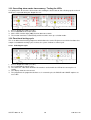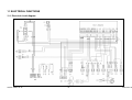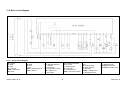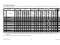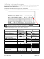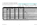
1
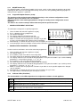
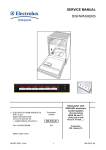
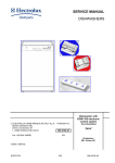
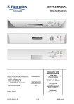
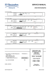
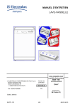
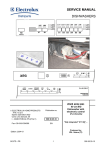
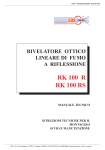
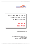
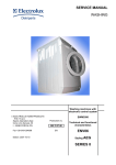
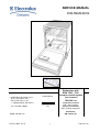
SERVICE MANUAL DISHWASHERS ELECTROLUX ITALIA S.p.A. Spares Operations Italy Corso Lino Zanussi, 30 I - 33080 PORCIA /PN (ITALY) Fax +39 0434 394096 Publication no. 599 35 63-72 EN (Functionalities) DIVA 60 cm Prod. N. 911 916 xxx F.S. - Free-standing Prod. N. 911 926 xxx B.I. - Partially integrated Production: ZM - Solaro (IT) Edition: 2010-01-28 SOI/DT 2003 - 01 eb Dishwasher with EDW 1500 - 1510 electronic control system 1 599 35 63-72 SOI/DT 2003 - 01 eb 2 599 35 63-72 CONTENTS 1 2 3 4 Purpose of this manual ........................................................................................................................... 5 PRECAUTIONS ...................................................................................................................................... 5 GENERAL CHARACTERISTICS............................................................................................................ 5 CONTROL PANEL.................................................................................................................................. 6 4.1 Control panel....................................................................................................................................... 6 4.1.1 4.1.2 4.1.3 4.1.4 4.2 4.3 Washing programmes......................................................................................................................... 8 Options................................................................................................................................................ 8 4.3.1 4.3.2 4.3.3 4.3.4 4.3.5 4.4 4.5 4.6 5.1 5.2 5.3 6 6.1 Activating/disactivating the buzzer ............................................................................................................11 Sequence of operations.................................................................................................................... 12 STRUCTURAL CHARACTERISTICS................................................................................................... 13 Structure ........................................................................................................................................... 13 Hydraulic and functional characteristics ........................................................................................... 13 Hydraulic circuit................................................................................................................................. 14 ELECTRICAL COMPONENTS AND THEIR FUNCTIONS .................................................................. 15 EDW1500-1510 Electronic control system ....................................................................................... 15 6.1.1 6.1.2 6.2 Functions of the circuit board....................................................................................................................15 Memory in the control system ...................................................................................................................15 Specifications for actuators and sensors.......................................................................................... 16 6.2.1 6.2.2 6.3 6.4 Components..............................................................................................................................................16 Sensors.....................................................................................................................................................16 Power supply and programme selection .......................................................................................... 17 Fill circuit ........................................................................................................................................... 18 6.4.1 6.4.2 6.4.3 6.4.4 6.5 Level and anti-overflow pressure switch ...................................................................................................18 Fill system .................................................................................................................................................18 Anti-flooding device...................................................................................................................................18 Intervention of the anti-overflow system....................................................................................................18 Control of water fill phase ................................................................................................................. 19 6.5.1 6.5.2 6.5.3 6.6 Static fill ....................................................................................................................................................19 Dynamic fill................................................................................................................................................19 Level stability control.................................................................................................................................19 Water fill time .................................................................................................................................... 19 6.6.1 6.6.2 6.6.3 6.7 6.8 Static fill time.............................................................................................................................................19 Dynamic fill time........................................................................................................................................19 Power supply interruption during water fill ................................................................................................19 Level stability during washing ........................................................................................................... 20 Washing system................................................................................................................................ 20 6.8.1 6.9 Control of the washing pump ....................................................................................................................20 Heating.............................................................................................................................................. 21 6.9.1 6.10 6.11 6.12 6.13 6.14 6.14.1 6.14.2 6.14.3 7 Cancelling a programme (reset)................................................................................................................10 Modifying a programme ............................................................................................................................10 Interruption of a programme (pause) ........................................................................................................10 Power failure ..................................................................................................................................... 10 Buzzer (only certain models) ............................................................................................................ 11 4.6.1 5 “ 3 in 1 Tablet”.............................................................................................................................................8 Extra rinse (rinse +).....................................................................................................................................8 “1/2 load”.....................................................................................................................................................9 “Sanitize”.....................................................................................................................................................9 Delayed start...............................................................................................................................................9 Modifying a programme .................................................................................................................... 10 4.4.1 4.4.2 4.4.3 4.7 ON/OFF button (S0)....................................................................................................................................7 Programme/Option buttons (S1-S6)............................................................................................................7 Indicator LEDs (LD7÷LD12)........................................................................................................................7 Display ........................................................................................................................................................8 Integrated detergent dispenser .................................................................................................................21 Disactivating the rinse-aid function ............................................................................................... 22 Drain.............................................................................................................................................. 22 Regeneration system .................................................................................................................... 23 Resin washing ............................................................................................................................... 23 Regeneration levels ...................................................................................................................... 24 Setting the regeneration level ...................................................................................................................24 “Blending” function ....................................................................................................................................24 Table of regeneration values ....................................................................................................................25 Drying.................................................................................................................................................... 25 7.1.1 “Turbo-dry” drying .....................................................................................................................................25 SOI/DT 2003 - 01 eb 3 599 35 63-72 8 8.1 Automatic cycle ..................................................................................................................................... 26 Turbidity sensor ................................................................................................................................ 26 8.1.1 8.1.2 Calculating the degree of soiling ...............................................................................................................26 Determination of the load..........................................................................................................................26 8.2 Automatic Programme ...................................................................................................................... 26 Alarms ................................................................................................................................................... 27 9.1 Table of alarms ................................................................................................................................. 27 10 Diagnostics mode / Options .................................................................................................................. 29 10.1 Accessing diagnostics mode......................................................................................................... 29 10.2 Reading the alarms and activating the individual components.................................................... 29 10.3 Cancelling alarm codes from memory / Testing the LEDs............................................................ 30 10.4 Functional testing cycle................................................................................................................. 30 9 10.4.1 10.5 10.5.1 10.5.2 Selecting the cycle ....................................................................................................................................30 Options available to Service Engineers ........................................................................................ 31 Selecting the extra cold rinse option .........................................................................................................31 Disabling pulse washing ...........................................................................................................................32 10.6 Exiting diagnostics mode .............................................................................................................. 32 11 ELECTRICAL FUNCTIONS.................................................................................................................. 33 11.1 Electrical circuit diagram ............................................................................................................... 33 11.2 Basic circuit diagram ..................................................................................................................... 34 11.2.1 Key to circuit diagram ...............................................................................................................................34 11.3 Table of programmes .................................................................................................................... 35 11.4 Checking the efficiency of the components .................................................................................. 36 11.5 Measurement points on the board wiring connector ..................................................................... 36 12 QUICK GUIDE TO THE SPECIAL FUNCTIONS................................................................................. 37 SOI/DT 2003 - 01 eb 4 599 35 63-72 1 Purpose of this manual The purpose of this Service Manual is to provide Service Engineers, who already have the basic knowledge necessary to repair household dishwashers, with technical information regarding dishwashers featuring the EDW1500-1510 electronic control system. These appliances are manufactured at Solaro (Italy). The EDW1500-1510 control system consists of a main circuit board and a control/display board. Both boards are housed in a single plastic container. This system is used in free-standing and partially integrated versions with “DIVA” 60 cm structures. This Manual describes: • General characteristics • Control panel and programmes • Technical characteristics • Guide to diagnostics For more detailed information regarding the hydraulic circuits and the structural characteristics of the appliances, refer to the Service Manual for presentation of the “DIVA” structure (publication number 599 35 55– 25). 2 PRECAUTIONS Electrical appliances must be serviced only by qualified Service Engineers. Always remove the plug from the power socket before touching internal components. 3 GENERAL CHARACTERISTICS Power supply Total power absorption Mains water supply Capacity 230 V / 50 Hz (limits: 187−254 V) 2300 W 2 Pressure Min. / Max. 5 − 80 N/cm 12 place settings Dimensions: - width - height - depth 59.6 cm 81.8 -87.8 cm 55.5 cm Controls - ON/OFF - Selection of programmes/options - Display Horizontal / Vertical Two-pole switch (separate from the electronic board) Button-actioned (min. 3, max. 6) Display 2,5 digits and LEDs Washing system Control of water level Water heating Temperature control Type of drying Safety devices / Alarms Combined / Pulse Pressure switch + Software Tube-enclosed heating element (2100 W) NTC temperature sensor Active / Turbo Total protection (hydraulic + Software) SOI/DT 2003 - 01 eb 5 599 35 63-72 4 CONTROL PANEL 4.1 Control panel The configuration of the control panel depends on the following: Typology of the electronic board: horizontal buttons vertical buttons Number of programme selection buttons (from a minimum of 3 to a maximum of 6) Number of LEDs (max.13) Position of the ON/OFF button (right or left) Version EDW1500 with horizontal buttons Version EDW1510 Version EDW1500 with vertical buttons Key S0 S1÷S6 LD1÷LD6 LD7÷LD12 SOI/DT 2003 - 01 eb ON/OFF button Programme/option selection buttons Programme/Option indicator LEDs Indicator LEDs phases / warnings (washing, drying, end of cycle, salt, rinse-aid) 6 599 35 63-72 4.1.1 ON/OFF button (S0) The ON/OFF button is featured on all models in the range, and is used to switch the appliance on and off. Switching off does not cancel the programme being executed. The corresponding pilot lamp [L0] lights to indicate that the appliance is powered. 4.1.2 Programme/Option buttons (S1-S6) The functions of the various buttons depend exclusively on the software configuration of each appliance, which can feature from 3 to 6 buttons. Also the selection of the washing programmes changes according to the configuration of each appliance. The buttons S1, S2, S3 are always featured because perform special functions. MODELS WITH DIRECT SELECTION To each button corresponds a specific programme: 1. 2. 3. Close the door and switch the appliance on [S0] Press a button to select a programme: The relative LED lights. The display shows the flashing time-to-end. The indicator LEDs of the phase of the cycle light. Within 3 seconds after the programme selection it is possible to set the eventual option or the delayed start (if available). 4. Automatically, 3 seconds after the last pressure of a button, the cycle starts. On the display the time-to-end lights steady and the LED of the current phase is on. MODELS WITH SEQUENTIAL SELECTION In these versions two buttons are used to select the programmes: 1. 2. 3. 4. 5. Close the door and switch the appliance on [S0] The display shows [ --] Press button [+] to select with an increasing order: The LEDs relative to the programme buttons light (if featured). The display shows the last selected flashing programme. Every time the button is pressed the following programme is selected (increasingly): 1 2 3..... Press button [- ] to select with a decreasing order: The LEDs relative to the programme buttons light (if featured). The display shows the last selected flashing programme. Every time the button is pressed the previous programme is selected: 7 6 5 ..... Within 3 seconds after the programme selection it is possible to set the possible option or the delayed start (if available). Automatically, 3 seconds after the last pressure of a button, the cycle starts. The digits and the LED indicating the current phase are on. 4.1.3 Indicator LEDs (LD7÷LD12) The functionalities of the LEDs depend on the configuration software of each appliance. Washing: lights when the washing phase is performed and during the selection (if featured). Drying: lights when the drying phase is performed and during the selection (if featured). End of cycle: lights when the programmes ended. Salt: indicates that the salt reservoir is empty. If the level of regeneration is set to “1” (no regeneration), this LED remains unlit at all times. Rinse-aid: indicates that the rinse-aid reservoir is empty. SOI/DT 2003 - 01 eb 7 599 35 63-72 4.1.4 Display The display, which consists of 2,5 digits, can indicate: The indicative time-to-end of the programme in minute. The countdown is carried out every minute and updated at the end of each programme phase (when the programme is updated it can decrease by more minutes at a time or stop for longer). The end of cycle [0] The possible delayed start time in hours (max 19h); the time decreases every hour. The selected regeneration level (during the regulation). A possible alarm code in case of failure. The condition of the special functions (no rinse-aid and). The condition of the functions that the Service can select. 4.2 Washing programmes The number and type of washing programmes depends on the configuration of the appliance. Wash (ºC) N. Rinses 1/2 load Sanitize 3 in 1 Rinse + Intensive 1 55 Intensive (maximum speed) 55 Intensive (short) 50 Normal Cold Normal (maximum speed) Cold Cold Normal 3 Rinses Cold Delicate Cold Energy label Axx Cold Energy label Short Energy label Auto performance E5 Cold (*) (Cold) Automatic 50-65 (*) Auto 1 Cold Soak Q4 -Short 30 min Q5 -Heat plates Q6 -Glassware Q7 68 68 68 68 68 55 55 50 55 3 3 3 2 2 3 2 2 2 ⊗ ⊗ ⊗ ⊗ ⊗ ⊗ ⊗ ⊗ ⊗ ⊗ ⊗ ⊗ ⊗ ⊗ ⊗ ⊗ ⊗ ⊗ ⊗ ⊗ ⊗ ⊗ ⊗ ⊗ ⊗ ⊗ ⊗ ⊗ ⊗ ⊗ ⊗ ⊗ ⊗ ⊗ ⊗ ⊗ 122 120 88 102 100 102 98 162 134 65 max 2 ⊗ ⊗ ⊗ ⊗ 141 50-68 -65 max -45 2-3 (1) 1 1 2 Auto ----- ⊗ ⊗ ⊗ ⊗ -- ⊗ -⊗ -⊗ ⊗ -⊗ -⊗ 92-115 12 (46) 31 30 73 Type Pre-wash (ºC) Possible options Programme I1 I2 I3 N1 N2 N5 N3 E1 E4 Min. ~ (*) models with turbidity meter only 4.3 Options 4.3.1 “ 3 in 1 Tablet” This option can be selected by pressing the corresponding button, and remains in memory until the same button is pressed again. This option modifies the phases of the programme in order to optimize performance when “3 in 1” detergent tablets are used: variation of the duration of the programme and the temperatures required to dissolve the detergent tablets. reduction of water exchange (partial drain phases) exclusion of introduction of rinse-aid exclusion of regeneration / resin washing 4.3.2 Extra rinse (rinse +) This option may be selected temporarily by pressing the button (if featured), or in “Service” mode. If this option is set by the service engineer, it remains in memory until disactivated (see relative section). This option adds one cold rinse (with pulse washing) with a duration of about 5 minutes. SOI/DT 2003 - 01 eb 8 599 35 63-72 4.3.3 “1/2 load” The 1/2 load option optimizes the washing cycle when only a small load is placed in the appliance. • 1/2 load button When this button is pressed, certain parameters of the selected washing cycle are modified: Exclusion of Pre-wash (if featured) Reduction of the washing temperature Reduction of the duration of the programme (up to 36 minutes) • Automatic 1/2 load When this button is not featured on the control panel, certain programmes may feature automatic detection of the half load. This system measures variations in the temperature during the initial heating phase. The temperature and the duration of the wash are both reduced. This option is not available in the following cycles: “Intensive”, “Short 30 minutes”, “Soak”, “Heating plates” and “Glassware”. 4.3.4 “Sanitize” This is a special option used to sanitize the dishes/cutlery. However, it is NOT compatible with the “Glassware” programme. During the final rinse, the temperature is maintained at 68°C for 10 minutes. If used together with the SOAK option, the system performs a special sanitizing programme which lasts approximately 46 minutes (1 hot rinse followed by 10 minutes at a constant temperature of 68°C) 4.3.5 Delayed start Proceed as follows to select the delayed-start time: 1. 2. 3. 4. Close the door and switch the appliance on by means of the S0 button. Press the button repeatedly to select the delayed-start time which appears flashing on the display. The time increases every hour up to 19h [ 1 2 3 .....19 0.. ]. Select the programme and the possible options. For some seconds the display shows the time-to-end of the cycle, then the delay time. 3 seconds after the last selection, the delay time is activated. The display lights steady and the countdown starts: the time decreases every hour [ 19 18 17... 1 0]. 5. During the countdown, till the programme starts, it is possible to modify the delay time or cancel it. 6. the programme starts automatically. The display shows the time-to-end of the cycle. The delayed-start countdown can also be selected as follows: 1. 2. 3. 4. Press button S0 to switch on the appliance. Select the programme and the possible options. Within 3 seconds, press sequentially the button to select the delay time. 3 seconds after the selection the delay time and the countdown start with the same modalities previously described. SOI/DT 2003 - 01 eb 9 599 35 63-72 4.4 4.4.1 Modifying a programme Cancelling a programme (reset) To cancel a programme that has already started, proceed as follows: 1. Open the door carefully and press buttons S2 - S3 together for approximately 2 seconds: the LED corresponding to the cycle being executed begins to flash. 2. After about two seconds, all the LEDs and the display switch off: the programme is now cancelled and the appliance returns to the selection mode. 4.4.2 Modifying a programme 1. Until a cycle has actually started (digit with flashing light), the settings selected can be modified at any time by pressing the appropriate buttons. 2. To modify a programme that has already started, first cancel it (see corresponding parag) and then perform the new selections. or: 1. Press the button of the new programme for about 6 seconds, the LED of the current programme begins to flash. 2. After about 6 seconds the LED of the old programme switches off and the LED of the new one lights: the possible options are deleted and have to be selected again. 4.4.3 Interruption of a programme (pause) Proceed as follows to interrupt a programme that has already started: 1. Press S0 to switch the appliance off. 2. To re-start the cycle, press S0 again: The programme starts from the point at which it was interrupted. 3. If you open the door the cycle interrupts: re-closing it, the programme starts (after a brief delay) from the point at which it was interrupted. Important! If the appliance is switched off or if the door is opened for more than 30 seconds during the drying phase, the cycle is considered to have been terminated after the regeneration phase; when the appliance is switched on again, it returns to programme selection mode. 4.5 Power failure The Power Failure function maintains the information relative to the cycle status even in the even of a power outage; when the power supply is restored, the cycle resumes from the point at which it was interrupted. If the power failure occurs during the drying phase, the cycle is considered to have been terminated after the regeneration phase. SOI/DT 2003 - 01 eb 10 599 35 63-72 4.6 Buzzer (only certain models) Normally this series of appliances does not feature the buzzer, but some models do. The buzzer sounds to indicate the end of cycle and in the event of an alarm condition. The buzzer sounds three times at the end of the cycle, but switches off immediately if the door is opened. If the user prefers to switch off the buzzer, it is necessary to press a combination of buttons. 4.6.1 Activating/disactivating the buzzer 1. Cancel any cycles that have been selected. 2. Press S0 to switch the appliance on. 3. Press buttons S2 and S3 at the same time until LEDs LD1, LD2 and LD3 begin to flash. 4. 5. 6. Press button S3: LEDs LD1 and LD2 switch off, while LD3 continues to flash. The condition of the buzzer is indicated by the display: 1b buzzer on, : 0b buzzer off Press button S3 again to disactivate/activate the buzzer To store this operation in memory: press button S0 and switch the appliance off or wait 60 seconds, the appliance is in selection mode. SOI/DT 2003 - 01 eb 11 599 35 63-72 4.7 Sequence of operations SELECTING THE CYCLE 1. Close the door. 2. Press S0 to switch the appliance on. The pilot lamp L0 lights. 3. Select the desired programme. The display shows the time-to-end or the programme no. flashing. The phase LEDs light. END EXECUTION OF THE CYCLE START 4. Within 3 seconds select the possible delayed start or the desired option (if featured) 5. Automatically, 3 seconds after the last pressure of a button, the cycle starts. The digits and the current phase LED light steady. 6. The time-to-end decreases every minute and is updated after every cycle phase. The LED indicates the current phase. 7. To interrupt a current programme: Switch the appliance off with S0 (or open the door) To start it again, press S0 (and close the door) 8. To cancel a current programme: Press S2 – S3 simultaneously for about 2 seconds. 9. At the end of the programme: The buzzer sounds at intervals. The END OF CYCLE LED lights. The display shows [0]. 10. Press S0 to switch the appliance off. SOI/DT 2003 - 01 eb 12 599 35 63-72 5 STRUCTURAL CHARACTERISTICS 5.1 Structure The appliance as a whole may be considered as consisting of four main assemblies: BASE – DOOR – TUB – HYDRAULIC SECTION The four assemblies are enclosed in a structure consisting of: - A lower front panel (secured by two screws) - Two lateral panels (secured by six screws). 5.2 Hydraulic and functional characteristics Turbo fan Drying duct Fill tank + condenser Counterweight Base Heater Wash pump Softener Sump SOI/DT 2003 - 01 eb Drain pump 13 599 35 63-72 5.3 Hydraulic circuit KEY 1 - Fill hose 2 - Fill hose with Acquacontrol 3 - Fill solenoid 4 - Regeneration solenoid 5 - Air-Break 6 - Steam condenser 7 - Regeneration chamber 8 - Salt Reservoir 9 - Resin Reservoir 10 - Level pressure switch SOI/DT 2003 - 01 eb 11 - Anti-overflow pressure switch 12 - Sump assembly 13 - Wash pump 14 - Tube-enclosed heating element 15 - Drain pump 16 - Non-return valve 17 - Drain hose 18 - Drying duct / fan 19 - Anti-flooding device 14 599 35 63-72 6 ELECTRICAL COMPONENTS AND THEIR FUNCTIONS 6.1 EDW1500-1510 Electronic control system The EDW1500 control system consists of a main circuit board and a control/display board. Both boards are housed in a plastic container. Version with horizontal buttons 6.1.1 Version with vertical buttons Functions of the circuit board DISPLAY BOARD LEDs Buttons Display µP ELECTRICAL LOADS SENSORS (Buzzer) MAIN CIRCUIT BOARD The circuit board receives signals relative to the cycle settings via the control/display board. The buttons and LEDs are also mounted on this board. The board also powers all the electrical components (solenoid valves, washing pump, detergent/rinseaid dispenser, drain pump, heating element, fan motor). The board controls the temperature of the washing water via an NTC sensor, as well as the speed of rotation of the washing pump according to the signal received from the tachymetric generator. The circuit board monitors the status of the pressure switch and the rinse-aid/salt sensors. 6.1.2 Memory in the control system µP Asynchronous external serial port ROM Power Fail and machine status RAM Synchronous internal serial p EEPROM (external to the µP) Configuration of the appliance Description of the cycle The main circuit board features an EEPROM memory (external to the microprocessor) which stores in memory data relative to the configuration, description of the cycle, cycle status in case of a power failure, and any alarm conditions. The configuration data (entered in the factory using a computer with a DAAS interface) determine the functionalities of the appliance (number and type of programmes, options, LEDs etc.). SOI/DT 2003 - 01 eb 15 599 35 63-72 6.2 6.2.1 Specifications for actuators and sensors Components POWER AVAILABLE TYPE OF ELECTRONIC CONTROL Wash pump Max 250W Triac Drain pump Max 100W Triac Heating element Max 2100W Relay Water fill solenoid Max 10W Triac Regeneration solenoid Max 10W Triac Detergent and Rinse-aid solenoid Max 10W Triac Fan motor Max 10W Triac TYPE OF COMPONENT 6.2.2 Sensors TYPE OF ELECTRONIC SIGNAL TYPE OF COMPONENT Salt sensor Digital 5 Volt Reed Rinse-aid sensor Digital 5 Volt Reed Analogue 5 Volt * NTC Analogue 5 Volt Opto-electronic Frequency Tachymetric generator Level sensor Digital - High voltage Pressure switch Door closure sensor Digital - High voltage Switch Anti-flooding sensor Digital - High voltage Switch TYPE OF SENSOR Temperature sensor Turbidity sensor (certain models only) Tachymetric sensor * NTC Temperature sensor * NTC COMPARATIVE VALUES Temperature °C 10 25 60 90 SOI/DT 2003 - 01 eb Nominal value Ω 9655 4850 1205 445 16 599 35 63-72 6.3 Power supply and programme selection The main board is powered by the closure of contacts 1-5 and 2-4 of the ON/OFF button (PU). The connectors used in this case are A2 (neutral) and B1 (line). The control/display board (user interface) is powered at 5V by the main board, making programme selection possible. When the door is closed, the main board detects the closure of the contacts of the switch (IP) across connectors B2-D1, and starts the washing programme. The same switch powers the electrical components. When the door is opened, the power loads are disconnected from the power supply and the cycle is paused. SOI/DT 2003 - 01 eb 17 599 35 63-72 6.4 Fill circuit 6.4.1 • • Level and anti-overflow pressure switch The level of water introduced into the appliance is determined by the level pressure switch (A) The anti-overflow pressure switch (B) ensures that the level of water does not exceed the safety threshold (causing overflow from the door). B A 6.4.2 Fill system The water fill solenoid valve is powered by triac TY2 on the electronic board (connector C7), by the door switch (IP) and by the anti-flooding microswitch (DA). The level of water in the sump is monitored by the pressure switch (RL). The electronic board constantly monitors the status of the pressure switch via a “sensing” line connected to connector C5: EMPTY if the contacts are closed on 1-2 FULL if the contacts are closed on 1-3 6.4.3 Anti-flooding device Intervention of the anti-flooding device causes the contacts of the microswitch (DA) to open, thus disconnecting the solenoid valve from the power supply. 6.4.4 Intervention of the anti-overflow system If the anti-overflow pressure switch (PA) should intervene, the closure of the contact on FULL (1-3) powers the drain pump (PS). The pump remains in operation until the contact returns to EMPTY (1-2). If the door is opened or the appliance is switched off, the drain pump is disactivated. SOI/DT 2003 - 01 eb 18 599 35 63-72 6.5 Control of water fill phase The quantity of water necessary to carry out the washing cycle is determined exclusively by the closure of the electrical contact of the pressure switch, which changes from EMPTY to FULL. This system ensures that, if the pressure switch re-opens on EMPTY, further water is introduced until it returns to FULL. The water fill phase consists of the following sub-phases: 6.5.1 Static fill With the motor switched off, the fill solenoid valve is energized and water is introduced into the appliance until the pressure switch signal switches to FULL. 6.5.2 Dynamic fill The dynamic fill is obtained by switching on the washing pump whose rotation causes the pressure switch to switch to EMPTY. Subsequently, the fill solenoid valve is energized and water is introduced until the switch returns to FULL. The speed of rotation of the motor determines the quantity of water introduced, since the electronic control system switches on the washing pump at a variable speed which depends on the washing system that will be performed in the phases subsequent to the water fill: In the case of “ctrl“ washing (at constant speed), the speed of rotation increases gradually to 2800 rpm In the case of “pw“ (pulse) washing, the speed of rotation increases gradually to 1900 rpm N.B.- Refer to the Table of Programmes for the definition of the washing system. 6.5.3 Level stability control The hydraulic circuit operates with maximum efficiency when the pressure switch signal remains stable on FULL. In practise, the quantity of water circulating in the sump allows the motor to run without speed fluctuations caused by cavitation. When the pressure switch signals FULL, the fill solenoid valve switches off. 6.6 Water fill time The aperture of the solenoid valve has a pre-set overall duration, which is subdivided into the various subphases of the fill: 6.6.1 Static fill time T.S. = max 90 seconds: This is the maximum time within which the pressure switch must switch to FULL. If the FULL signal is not received from the pressure switch within this time, the electronic control system interrupts the washing cycle and the appliance enters alarm condition [1 0]. 6.6.2 Dynamic fill time T.D. = T.S. x 3: This is the maximum time allowed for the entire fill phase within which the pressure switch signal must stabilize on FULL. • If the pressure switch signal does not stabilize on FULL within this period (T.S. x 3), the electronic control system switches off the fill solenoid (and the heating element, if switched on), and then allows the washing cycle to proceed until it is completed. In this situation, the alarm condition [F 0] is not displayed to the user, but may be accessed by the Service Engineer using a specific procedure. • If, during a 2800 rpm dynamic fill, the pressure switch never closes on FULL during the initial 60 seconds, the electronic control system interrupts the washing cycle and the appliance enters alarm condition [1 0]. 6.6.3 Power supply interruption during water fill If the water fill phase is interrupted by opening the door or due to a power failure, the contents of the counters are stored in memory; when the door is re-closed or when the power supply is restored, the water fill resumes from the point at which it was interrupted; the new counter values are added to those previously memorized. SOI/DT 2003 - 01 eb 19 599 35 63-72 6.7 Level stability during washing Once the fill phase has been completed, the cycle proceeds to the washing phase. The washing phase is carried out using cold or heated water, and the status of the pressure switch is monitored constantly to ensure that the hydraulic system functions correctly. Water replenishment cycles may be performed if necessary. If the pressure switch returns to EMPTY during the washing phase, the fill solenoid is energized for a maximum time equivalent to T.S. x 3 (maximum allowable total fill time). If this time is exceeded, the washing cycle is completed, but no further supplementary fills are performed. In this situation, alarm condition [F 0] is stored in memory. This alarm code is not displayed to the user, but can be accessed by the Service Engineer using a specific procedure. 6.8 Washing system The appliance features the classic washing system in which the mechanical washing action is obtained by the rotation of the washing pump which, by ducting water into the hydraulic circuit, actions the two spray arms simultaneously. The washing pump is actioned by an asynchronous motor with a start-up capacitor (3µF - 450VL). The washing pump rotates in a counter-clockwise direction (seen from the impeller side) and is fitted with a tachymetric generator. In order to optimize the washing programmes, two washing systems can be applied: “ctrl“ “pw“ Washing at constant speed (2800 rpm) (maximum speed of the motor). Pulse washing at 1600 - 2800 rpm. This washing system is controlled by the electronic control system, which actions the washing pump alternately at two speeds (minimum and maximum speed) for short periods. MOTOR SPEED PERIOD OF OPERATION Maintenance 1600 rpm 4 sec PW1 Pulses 2800 rpm 0.8 sec The ctrl and pw speeds are configurable. For further details, refer to the cycles tables relative to the specific model. 6.8.1 Control of the washing pump The washing pump (PL) is powered by triac TY4 on the circuit board (connector C3), by the door switch (IP) and by the ON/OFF switch (PU). The main circuit board controls the speed of rotation according to the signal received from the tachymetric generator (T) connected to connectors E1-E2. This signal is used for: Control of the washing system (ctrl or pw) Control of the pump motor safety devices and the relative alarms Control of the dynamic fill SOI/DT 2003 - 01 eb 20 599 35 63-72 6.9 Heating The heating element is enclosed in a protective tube, and is used to heat the washing water (but does not switch on during the drying phase) The heating element is fitted to the outlet of the washing pump and connected to the duct which feeds the upper spray arm. The heating element (RR) is powered by relay RL1 on the circuit board (connector A1), by the ON/OFF switch (PU) and by the level pressure switch (RL), which must be set to “FULL” (contact closed on 1-3). Two safety thermostats are fitted to the heating element: - an automatic-reset thermostat which intervenes at 98°C - a thermostat with a thermal fuse (206°C). The temperature of the water is controlled by the main circuit board via an NTC sensor (ST) which is connected to connectors G5-G6. 6.9.1 Integrated detergent dispenser The detergent dispenser is a plastic container consisting of two separate sections. The first (A) contains the detergent; the second (B) contains the Rinseaid. The dispenser is of the single-coil type, and uses a single electrical coil, connected to a mechanical system, for both functions. When the coil is energized, it actions the mechanism via a series of levers to introduce detergent in a determined sequence (first detergent, then rinse-aid). B A The coil of the detergent dispenser (DD) is powered by the circuit board via triac TY5 (connector D7) at certain points during the cycle, thus ensuring correct dosage. The circuit is closed by the contacts of the ON/OFF switch (PU) and the door switch (IP). Some models feature a rinse-aid sensor whose reed contact (SB) is connected to connectors F3-F4 on the circuit board. The absence of rinse-aid causes the contact to close, which lights the corresponding LED (on the display board). SOI/DT 2003 - 01 eb 21 599 35 63-72 6.10 Disactivating the rinse-aid function Introduction of rinse-aid may be disactivated by the user by pressing a combination of buttons. In this case, the Rinse-aid LED (if featured) will also be disactivated. 1. Cancel any cycles that may have been selected. 2. Press S0 to switch the appliance on. 3. Press buttons S2-S3 simultaneously, and hold down until LEDs LD1, LD2 and LD3 begin to flash. 4. Press button S2: LEDs LD1 and LD3 switch off, while LD2 continues to flash. The condition of the function is indicated by the display: 1d rinse-aid function is operative, 0d rinse-aid function is inoperative 5. Press button S2 again to disactivate/activate the rinse-aid function. 6. To store this setting in memory: press button S0 and switch the appliance off; alternatively, wait for 60 seconds (appliance in selection mode) 6.11 Drain The drain pump (PS) is powered by triac TY3 (connector C1) and via the contacts of the ON/OFF switch (PU) and the door switch (IP). At the end of the drain phase, a control procedure is performed to check that the contact of the level pressure switch is open on EMPTY. If this is the case, the appliance proceeds to the subsequent phase. If, as a result of a problem in the drain phase, the pressure switch contact remains closed on FULL (i.e. if there is water in the hydraulic circuit), the drain phase is repeated. On completion of this second drain phase, the status of the pressure switch is again checked. If it is still closed on FULL, alarm [i20] is generated (failure to drain). The time-out for each of these two phases is 120 seconds. N.B. The washing programmes always begin with a drain phase. SOI/DT 2003 - 01 eb 22 599 35 63-72 6.12 Regeneration system Regeneration of the softening system, whose duration is approximately 4 minutes, is normally performed at the beginning of the drying phase. Each time regeneration is performed (the regeneration solenoid 4 is energized), the chamber is completely emptied (about 230 cc of water). Regeneration is controlled by the electronic control system “Ad Hoc”, i.e. not at each washing cycle, but rather at intervals determined by the level of regeneration selected. If level [1] is selected, regeneration is never performed and the SALT LED (if featured) always remains unlit. If level [10] is selected, regeneration is performed twice during each cycle; first at the end of the washing phase, and then at the beginning of the drying phase. The regeneration solenoid (ER) is powered by triac TY1 (connector C9 on the circuit board) and by the contacts of the ON/OFF switch (PU) and the door switch (IP). Some models feature a salt sensor whose reed contact (SS) is connected to connectors F1-F2 on the circuit board. The absence of salt causes the contact to close, which lights the corresponding LED (on the display board). 6.13 Resin washing Washing of the resins contained in the softening system is performed at the beginning of each washing cycle. In practise, the solution of salty water (regeneration water) remains deposited in the resin container from the end of the last completed cycle until the subsequent cycle. If the regeneration level is set to [10], washing of the resins is performed once at the beginning of the washing cycle and then again immediately after the regeneration process performed at the end of the washing phase. The regeneration sequence is as follows: a. b. c. d. e. Drain (30 seconds) Water fill to correct level Drain (10 seconds) Water fill (15 seconds) Complete drain SOI/DT 2003 - 01 eb 23 599 35 63-72 6.14 Regeneration levels The counter for execution of the “Ad Hoc” regeneration process is governed by the electronic control system on the basis of the duration of the fill phases (i.e. the quantity of water introduced), and NOT on the number of cycles. Regeneration can be set to one of 10 levels. If regeneration is set to level [1], the procedure is not performed and the Salt LED remains unlit. 6.14.1 Setting the regeneration level 1. Cancel any cycles that may have been selected. 2. Press key S0 to switch the appliance on. 3. Press buttons S2-S3 simultaneously, and hold down until LEDs LD1, LD2 and LD3 begin to flash. 4. 5. Press button S1: LEDs LD2, LD3 switch off, while LD1 continues to flash. The regeneration level is shown by the display [ 5L ]. Press button S1 sequentially to modify the level of regeneration. Each time the button is pressed, the regeneration level increases by 1 level. If S1 is pressed after the th 10 level has been reached, the setting returns to level 1. [ 5L 6L 7L ..... 10L 1L 2L.... ] 6. To store this setting in memory: press button S0 and switch the appliance off; alternatively, wait for 60 seconds (selection mode) 6.14.2 “Blending” function This function is performed inside the fill tank during the water fill phase which, depending on the position of the selector, automatically blends the softened water with the unsoftened water present in the appliance. In practice, the softened water is introduced into the appliance through the softening system, while the unsoftened water flows via an open by-pass duct directly through the steam venting ring. If the level of regeneration is set to between 1 and 4, it is advisable to activate the BLENDING function to mix softened water with unsoftened water. This function optimizes the consumption of salt thus preventing the possibility of corrosion of glass recipients due to excessively soft water. When the BLENDING function is activated, the percentage of unsoftened water introduced into the dishwasher is 15%. The BLENDING function is activated using the selector knob located inside the tub, on the left side, in the vicinity of the steam venting grille. Position of selector pos.1 = blending ACTIVATED. pos.2 = blending DISACTIVATED. SOI/DT 2003 - 01 eb 24 599 35 63-72 6.14.3 Table of regeneration values Level 1 2 3 4 *5 6 7 8 9 10 Water introduced Aperture of Position of between regeneration selector in Display regeneration solenoid the tub cycles litres sec nº 1L --0 1 2L 130 240 1 3L 94 240 1 4L 70 240 1 5L 53 240 2 6L 37 240 2 7L 20 240 2 8L 15 240 2 9L 10 240 2 10 L 3 2x240 2 * “5” = factory-set level Position of selector in tub: “2” Hardness of the water º F (TH) 0>8 9 > 14 15 > 20 21 > 30 31 > 40 41 > 50 51 > 60 61 > 70 71 > 80 81 > 90 º D (dH) 0> 4 5>8 9 > 11 12 > 17 18 > 22 23 > 28 29 > 33 34 > 39 40 > 45 46 > 50 7 Drying ACTIV-DRY TURBO-DRY In these dishwashers, the dishes are dried by means of a steam condensation process. The drying system is based on the circulation of the hot air produced during the hot rinse, in which the steam circulates inside the condenser of the fill tank. The condenser is a condensation chamber filled with water (cold wall); contact between the hot air and the cold wall results in the condensation process. Depending on the type of appliance, one of two drying systems is used: - "ACTIVE - DRY" drying - "TURBO - DRY" drying. 7.1.1 “Turbo-dry” drying Certain models feature a forced-air drying system. The steam is drawn in by the fan located inside the upper duct and routed towards the condenser in the fill tank, from which it returns to the tub through the steam venting ring. The fan motor (MV) is powered by triac TY6 (connector D3 on the circuit board) and by the contacts of the ON/OFF switch (PU) and the door switch (IP). The drying time is variable and pre-defined for each washing cycle. In some programmes, the fan remains in operation for about 20 minutes after the end of the cycle; if the door is opened, the fan switches off. SOI/DT 2003 - 01 eb 25 599 35 63-72 8 Automatic cycle 8.1 Turbidity sensor Certain models which feature the turbidity sensor may also feature a special “automatic” programme which optimizes the cycle according to the size of the load and the degree of soiling. This sensor is positioned externally to the sump, in direct contact with the water. A single container houses the NTC sensor (for control of the washing temperature) and the infra-red opto-electronic sensor, which controls the turbidity of the water and therefore the degree of soiling that it contains. 8.1.1 Calculating the degree of soiling Measurement of the level of turbidity is performed during the cold pre-wash. The photoemitting diode, which is powered by the circuit board (connector G7), transmits a beam of light to the photoreceiver. The circuit of the photoreceiver (connector G8 on the circuit board - G6 is the common contact) is traversed by a certain current whose intensity is proportional to the quantity of light received (i.e. inversely proportional to the level of turbidity). The microprocessor measures the signal present in the circuit, and can thus determine the most appropriate cycle according to the quantity of soiling present in the water. 8.1.2 Determination of the load The quantity of dishes in the load (full load or 1/2 load) is determined during the initial heating phase during washing by controlling the rate at which the temperature of the water increases (NTC sensor, connector G5). temperature 1/2 load threshold Full load: when the inclination of the curve is below a certain threshold which is memorized as standard. full load Half load: when the inclination of the curve is above the standard threshold. time 8.2 Automatic Programme The table below shows the variations in the programme phases according to the type of soiling and the size of the load. Type Load Full Full Half Half Programme phases Heavy soil Yes No Yes No SOI/DT 2003 - 01 eb Pre-wash Wash Cold 68º C 55º C 55º C 50º C First rinse Second rinse Hot rinse Drying 68º C 24 min. Cold Cold 26 no 599 35 63-72 9 Alarms In the event that an abnormal situation should occur which might affect the correct operation of the appliance, the circuit board causes a safety system to intervene. In most cases, this interrupts the washing cycle. The last three alarm conditions are stored in memory. Using a special procedure available only to Service Engineers, it is possible to read all the alarms stored in memory. However, only four current alarm conditions are displayed to the user. The alarms are displayed by the display and with a series of “beeps” from the buzzer (only certain models). 9.1 Table of alarms No. flashes of end-ofcycle LED and “beeps” Displayed to the user Description of the alarm condition YES Water fill time-out (The pressure switch does not close on FULL after 90 sec. static fill, or never closes on “FULL” during the initial 60 sec of the dynamic fill at 2800 rpm) The drain pump switches on, then the cycle stops i20 YES Water drain time-out (The pressure switch does not return to EMPTY after two drain phases lasting 120 seconds) (**) The drain pump switches on, then the cycle stops i30 YES Intervention of Anti-flooding system (the drain pump switches on) The cycle is interrupted and the drain pump switches on YES Motor triac short-circuited (the washing pump runs uncontrolled at maximum speed) Water fill to level (if necessary), disactivation of the other actuators, cycle interrupted. The washing motor runs at maximum speed and the alarm is displayed. Type of alarm i10 i50 Machine status Possible causes Tap closed; water mains pressure too low; fill solenoid / wiring faulty; hydraulic circuit of pressure switch obstructed; level pressure switch / wiring faulty; circuit board faulty (solenoid triac shortcircuited) Drain circuit obstructed/blocked; drain pump interrupted or jammed (foreign bodies); level pressure switch blocked on FULL (1-3); hydraulic circuit of pressure switch obstructed; wiring faulty; circuit board faulty Water leakage from the tub - sump and various connections (pump, upper spray arm duct etc.); floating sensor blocked mechanically; microswitch faulty; fill solenoid blocked mechanically; circuit board faulty (solenoid triac short-circuited); wiring faulty Circuit board faulty (**) If inside the appliance there is no water at all (correct drain) but this alarm is displayed, check the heater (possible dispersion) and the anti-interference suppressor. SOI/DT 2003 -01 eb 27 599 35 63-72 Type of alarm i60 No. flashes of end-ofcycle LED and “beeps” 6 Displayed to the user Description of the alarm condition Machine status Si Heating Time-out (the check takes place every 3 minutes: the temperature must increase by a certain amount at each step) Overheating Temperature higher than 78°C The programme continues to the end without heating (the washing result will probably be unsatisfactory) The cycle stops and the drain pump starts. The programme continues to the end without heating (the washing result will probably be unsatisfactory) Machine inoperative: no selection possible (*) The fault occurs when switching on: no selection possible (*) The programme continues as if a “heavy soiling” condition had been detected. The heating element is switched off. If the fault persists after the Time-out, the washing pump operates at maximum speed and the alarm code is stored in memory (the cycle continues) The cycle continues until the next phase without supplementary fills and without heating. The error is cancelled on completion of a drain phase. NO i70 7 NO NTC sensor short-circuited or open i80 8 NO Communication error between the microprocessor and the EEPROM i90 9 NO Problems with software configuration ib0 11 NO Problems with the turbidity meter [if featured] (Calibration Time-out) NO Problems with the washing motor: no signal from the tachymetric generator (washing pump powered, but no signal from the generator) NO Water replenishment Time-out (3 times during the T.S. Time-out) id0 iF0 13 15 Possible causes Heating element faulty; intervention of safety thermostats (open); wiring faulty; NTC sensor (poor thermal contact); insufficient water circulating in the tub; washing pump faulty (impeller stripped); circuit board faulty. NTC sensor faulty; wiring short-circuited / open; circuit board faulty. Circuit board faulty. Circuit board faulty (configuration software incorrect). Turbidity sensor faulty; sensor wiring faulty; circuit board faulty. Motor winding interrupted / short-circuited; motor jammed (foreign bodies); wiring to washing motor faulty; motor capacitor faulty; Tachymetric generator interrupted / short-circuited; circuit board faulty. Dishes upside-down; central filter clogged; excessive foam; leaks from the sump-pressure switch coupling; pressure switch faulty / false contacts. (*) If it is not possible to access diagnostics mode, switch the appliance off and then on again to check that this is not caused by a temporary fault. Before replacing the circuit board, check that it is correctly powered by controlling the following Continuity of the power cable Correct operation of the suppressor Closure of the door switch contacts Continuity of the wiring between connectors A2/B1 on the circuit board and the suppressor. SOI/DT 2003 -01 eb 28 599 35 63-72 10 Diagnostics mode / Options A single procedure can be used by Service Engineers to access the diagnostics system. After accessing diagnostics mode, the Engineer can: read / cancel the alarms, check for correct operation of the various components of the appliance, start the diagnostics cycle and select the options available to Service Engineers. 10.1 Accessing diagnostics mode 1. Switch off the appliance. 2. Press buttons S1-S3 simultaneously and hold down. 3. Press key S0 to switch the appliance on, still holding down buttons S1 - S3 until LEDs LD1, LD2 and LD3 begin to flash. 10.2 Reading the alarms and activating the individual components 1. 2. Access diagnostics mode (see 10.1). Press button S1 to start the function. LEDs LD2 and LD3 switch off; LD1 continues to flash. The first alarm stored in memory is displayed [ ix0 ] (for the codification see the summary table of the alarms – pages 27, 28). 3. Press S1 to display the other two alarms and to activate the electrical components. The display shows, after the first three alarms, the number corresponding to the activated function. 4. All the positions can be repeated by pressing sequentially S1. Activation S1 1 2 3 4 5 6 7 8 9 10 Activated function Reading of the last alarm occurred Reading of the last alarm but one occurred Reading of the last alarm but two occurred Activation of the solenoid regeneration Activation of drain pump Water fill solenoid to level Heating (only if water level is OK!) Washing pump at 2800 g/’ Detergent/rinse-aid dispenser Drying fan (if turbo-dry) The components are powered when the door is closed: open the door to select a different component, then re-close the door. If button S1 is not pressed for 60 seconds, the system automatically exits diagnostics mode). SOI/DT 2003 -01 eb Display 29 599 35 63-72 10.3 Cancelling alarm codes from memory / Testing the LEDs It is good practise to cancel the alarm codes after reading the alarm code or after effecting repairs to check whether it is repeated during the diagnostics test. 1. 2. Access diagnostics mode (see 10.1) Press button S2 to cancel the alarms. All the LEDs and the digits [188 ] flash for about 30 seconds. The function terminates automatically and the machine enters pre-selection mode. 10.4 Functional testing cycle This is an abbreviated washing programme which allows the Service Engineer to test all the functions that comprise a traditional washing cycle; in effect, the system simulates a normal cycle. 10.4.1 Selecting the cycle 1. Access diagnostics mode (see 10.1) 2. Press button S3 to start the cycle. The LEDs LD1, LD2 switch off while LD3 continues to flash while the LED of the current phase is steady. The display shows the time-to-end. The programme the programme behaves as in a normal cycle; the PAUSE and CANCEL options are accessible. SOI/DT 2003 -01 eb 30 599 35 63-72 10.5 Options available to Service Engineers In particular circumstances, i.e. if the user reports unsatisfactory washing results, a special procedure, available only to Service Engineers, can be used to select two supplementary options designed to improve performance: • Extra cold rinse. • Disabling of pulse washing (PW), replaced by continuous washing (Ctrl). 10.5.1 Selecting the extra cold rinse option Using the procedure described below, it is possible to add a supplementary cold rinse in all the washing programmes. This improves the quality of the rinse in case of necessity. 1. Access diagnostics mode (see 10.1). 2. Press buttons S1-S2 simultaneously. The display indicates the status of the function: [ 0A ] extra rinse not selected, [ 1A ] extra rinse active. 3. Press button S1 to activate and disactivate this function. [ 0A ] extra rinse not selected, [ 1A ] extra rinse selected. 4. To store the operation in memory: press key S0 and switch the appliance off; alternatively, wait for 60 seconds (appliance in selection mode). SOI/DT 2003 -01 eb 31 599 35 63-72 10.5.2 Disabling pulse washing Certain programmes use the pulse washing system (PW). Using the procedure described below, the Service Engineer can modify this system so that Ctrl (continuous) washing is used in all those programme which normally use the PW system. This intensifies the washing action even in delicate programmes. Disactivation/activation mode 1. Access diagnostics mode (see 10.1) 2. Press buttons S2-S3 simultaneously. The display indicates the status of the function: [ 0P ] continuous washing “Ctrl”; [ 1P ] pulse washing “PW” active. 3. Press button S2 to activate and disactivate this function: [ 0P ] continuous washing “Ctrl”; [ 1P ] pulse washing “PW” active. 4. To store the operation in memory: press key S0 and switch the appliance off or wait for 60 seconds (appliance in selection mode) 10.6 Exiting diagnostics mode 1. To exit the diagnostics cycle, press key S0 and switch the appliance off. or: 2. wait 60 seconds: the appliance returns to programme selection mode. SOI/DT 2003 -01 eb 32 599 35 63-72 11 ELECTRICAL FUNCTIONS 11.1 Electrical circuit diagram SOI/DT 2003 -01 eb 33 599 35 63-72 11.2 Basic circuit diagram 11.2.1 Key to circuit diagram AR = Orange BI = White BL = Blue CE = Light blue GI-VE = Yellow-Green MA = Brown SOI/DT 2003 -01 eb NE = Black RO = Pink VI = Lilac AA/DA = Anti-flooding device Beamer = Beamer CO = Capacitor DD = Detergent/ Rinse-aid dispenser EC = Fill solenoid ER = Regeneration solenoid GA = Suppressor IP = Door switch MR = General terminal block MV = Fan motor PL = Washing pump PS = Drain pump PU = Pushbutton array PR/RL = Level pressure switch 34 PA = Anti-overflow pressure switch RR = Heating element SB = Rinse-aid sensor SS = Salt sensor Turbidity = Turbidity sensor ST = Temperature sensor TAC/T = Tachymetric generator TS = Safety thermostat Main Board = Main board User Interface = Display board 599 35 63-72 11.3 Table of programmes The table below lists the phases of the programmes for this type of appliance. As these can be configured differently, refer to the relative documentation for the specific cycles available for each model. st 1 Cold Rinse Wash time (minutes) Type of Wash Wash time (minutes) Type of Wash Heating (Temperature in °C) Wash time after heating (min.) Type of Wash Drying (min.) Cycle time (minutes) I1 I2 I3 N1 N2 N5 N3 Intensive 1 Intensive (ctrl) Intensive (short) Normal (PW) Normal (ctrl) Normal 3 Rinses Delicate 55°C 55°C 50°C 10' 10' 2,5' ctrl ctrl ctrl 55°C 55°C 50°C 5' 5' 10' 68°C 68°C 68°C 14' 14' --- ctrl ctrl ctrl 3’ (<65°C) 3’ (<65°C) 5’ (<68°C) 3’ 3’ 5’ PW1 ctrl ctrl 3’ 3’ 5’ 3’ 3’ 5’ PW1 ctrl ctrl 5’ 5’ 5’ PW1 PW1 PW1 68°C 68°C 68°C 1' ----- PW1 ctrl ctrl 24’ 24’ 6’ 122’ 120’ 88’ ------- 6' 6' 6' ctrl ctrl ctrl 50°C 50°C 50°C 4' 4' 4' 68°C 68°C 68°C 8' 8' 8' ctrl ctrl ctrl ----3’ (<65°C) 4’ 4’ 3’ PW1 ctrl ctrl ----3’ ----3’ ----ctrl 5’ 5’ 5’ PW1 PW1 PW1 68°C 68°C 68°C 1' ----- PW1 ctrl ctrl 24’ 24’ 24’ 102’ 100’ 102’ --- 6' PW1 2' 55°C 12' PW1 --- 4’ PW1 --- --- --- 5’ PW1 68°C 1' PW1 24’ 98’ E1 Energy label Axx --- 10' 42' --- --- PW1 5’ (<60°C) --- PW1 --- --- --- 4’ PW1 16’ <68°C 2' PW1 54’ 162’ E4 Energy label (Short) --- 6' 2' 55°C 12' PW1 --- 4’ PW1 --- --- --- 5’ PW1 54’ 134’ Energy label (Auto) --- 8' 37' --- --- PW1 5’ (<60°C) --- PW1 --- --- --- 2’ 2' PW1 44’ 141’ --- 8' PW1 16’ <68°C 3x5” 15-17’ (2800) <68°C PW1 68°C 2' E5 50°C 15,5’ PW1 <62°C PW1 50°C 14-16.5’ PW1 <65°C ctrl 50°C --- 8' PW1 Type Programme Auto 1 Automatic 50-65 Q4 Soak Q5 Short 30 min. --- --- --- Q6 Q7 Plate heating Glassware ----- ----- ----- --14,5’ <65°C --45°C Wash time after heating (min.) 2nd Heating (Temperature in °C) Wash time after heating (min.) Wash time (minutes) Type of Wash Dry Wash time (minutes) Hot rinse Wash time (minutes) Extra Rinse Type of Wash 2nd Cold Rinse 1st Heating (Temperature in °C) Wash Type of Wash Pre-wash Heating (Temperature in °C) Wash time after heating (min.) Programmes 4' 68°C 8' ctrl --- 4’ PW1 --- --- --- 5’ 1' PW1 24’ 92-115’ --- --- --- --- --- --- --- --- --- --- --- --- --- --- --- --- 12’ --- --- --- ctrl --- --- --- --- --- --- 5’ PW1 9’ <67°C --- ctrl --- 31’ --9' ----- ----- --PW1 --5’ (<60°C) ----- --PW1 ----- ----- ----- --3’ --PW1 68°C 60°C 2' PW1 PW1 --24’ 30’ 73’ N.B.: The overall times for the programmes (duration) are approximate, and do not take into consideration the extra rinse, which may be selected as an option. The various phases do not include the times for regeneration/washing of the resins which, being performed “Ad Hoc”, are not carried out at every cycle (see sections 6.12 and 6.13) ctrl Continuous washing at 2800 rpm. PW Pulse washing at 1600 > 2800 rpm. SOI/DT 2003 -01 eb 35 599 35 63-72 11.4 Checking the efficiency of the components In order to facilitate the control procedure for the components to be tested, a TEST PROCEDURE has been created which indicates the point to which the probes of the tester should be applied and the correct theoretical value for each component tested. Remove the door and detach all the connectors from the main board. Connect the probes of the tester to the appropriate points on the connector. Compare the ohmic reading with the theoretical value. Care should be taken relative to the position of connector "A1" - "A2": if this connector is replaced in the incorrect position (back-to-front), the appliance will not function. The board will not accept any commands since the power supply will be disconnected. 11.5 Measurement points on the board wiring connector LIST OF COMPONENTS PROBE CONTACTS L B1 N A2 CORRECT VALUES (RR) - HEATING ELEMENT + (TS) - SAFETY THERMOSTAT A1 C5 (PR) - LEVEL PRESSURE SWITCH B1 C5 (PA) - ANTI-FLOODING PRESSURE SWITCH (IP) - DOOR MICROSWITCH C1 A2 (DD/DB) - INTEGRATED DISPENSER B2 D1 D5 D7 (SB) - RINSE-AID SENSOR F3 F4 (SS) - SALT SENSOR F1 F2 (ST) - TEMPERATURE SENSOR G5 G6 (GT) - TACHYMETRIC SENSOR E1 E2 D1 D3 D1 C9 * POWER CABLE & (PU) - ON/OFF SWITCH (MV) - FAN MOTOR (ER) - REGENERATION SOLENOID (EC) - FILL SOLENOID + (AA) - ANTI-FLOODING DEVICE D1 C7 C11 C3 (PL) - WASH MOTOR To the two motor wires (blue) / (red) (PS) - DRAIN MOTOR C11 C1 NOTES 0Ω INFINITE 0Ω INFINITE 0Ω 0Ω connected in series (2100W) on "EMPTY" (1-2) on "FULL" (1-3) on "EMPTY" (1-2) on "FULL" (1-3) Door closed 1.500 Ω ± 8% INFINITE 0Ω INFINITE 0Ω 4850 Ω ± 5% 1205 Ω ± 5% 210 Ω ± 8% OK with Rinse-aid without Rinse-aid with salt without salt (at 25ºC) (at 60ºC) OK 0Ω 25 Ω ± 8% with ON/OFF key pressed 7750 Ω ± 8% OK 6 KΩ Ω ± 8% OK 3.800 Ω ± 8% connected in series 50 Ω ± 8% start-up winding 180 Ω ± 8% auxiliary winding 180 Ω ± 8% OK Note: - *) = Measurement points L and N refer to the pins of the plug fitted to the power cable. SOI/DT 2003 -01 eb 36 599 35 63-72 12 QUICK GUIDE TO THE SPECIAL FUNCTIONS The table below briefly describes how each of the special functions available to the user and to the Service Engineer can be used. Function USER (*) Select regeneration Disactivate rinseaid Disactivate buzzer SERVICE ENGINEERS Display of alarms and components diagnostics Cancel alarms stored in memory Test cycle Extra rinse Disable buttons Exit / Memorize Activation of the function Keys Led(s) LD1 + LD2 [S1 + S2] flashing S0 (On/Off) S0 (On/Off) [S2 + S3] S0 (On/Off) [S2 + S3] [S1 + S3] S0 (On/Off) Keys Starting the function Led(s) S1 LD1 flashing S2 LD2 flashing LD1 + LD2+ LD3 flashing LD1 + LD2+ LD3 S3 LD3 flashing S1 LD1 flashing flashing LD1 + LD2 + LD3 flashing Brief description / Comments (description on page 24 / chapter 6.14). Press S1: Liv….[1L]……[2L]….[3L]…...[ 4L]……[ 5L]…. [ 6L ]…...[ 7L] .…[ 8L]……[ 9L]….…[10L] °F… >8 ….. >14 ..…>20 ….. >30 ….. >40 ….. >50 ….. >60 ….. >70 ….. >80 ….... >90 °D… >4 …... >8 ..…. >11 ..... >17 ….. >22 ….. >28 ….. >33 ….. >39 ….. >45 ……. >50 (description on page 22 / chapter 6.10) Press S2 and press again: 1d = rinse-aid activated, 0d = not activated (description on page 11 / capitolo 4.6.1) Press S3 and press again: 1b = buzzer activated, 0b = not activated (description on page 29 / capitolo 10.2). Press button S1: [i.0] [i.0] [i.0] [4 ] [ 5] [ 6] [7] [ 8] [ 9 ] [10] AL 1 AL2 AL 3 ER PS EV RR PL DD MV [S1 + S3] LD1 + LD2 + LD3 LD2 S2 (description on page 30 / capitolo 10.3) flashing flashing All the LEDs and digits flash for 30 sec. S0 (On/Off) [S1 + S3] LD1 + LD2 + LD3 LD3 S3 (description on page 30 / capitolo 10.4) flashing flashing The cycle starts automatically S0 (On/Off) [S1 + S3] [S1 + S2] LD1 + LD2 + LD3 LD1 (description on page 31 / capitolo 10.5.1) flashing flashing Press S1 and press again: 1A = rinse activated 0A = not activated S0 (On/Off) S1 [S1 + S3] [S2 + S3] (description on page 31 / capitolo 10.5.2) LD1 + LD2 + LD3 LD2 Press S2 and press again: 1P = pulse wash PW activated; flashing flashing S0 (On/Off) S2 0P = continuous wash In order to memorize the functions or exit diagnostics mode, press key S0 to switch the appliance off. In most cases, memorization / exit take place automatically after 60 seconds (in which case the appliance returns to pre-selection mode) (*) To activate the functions available to the user, no cycles must be selected (i.e. the appliance must be in pre-selection mode). SOI/DT 2003 -01 eb 37 599 35 63-72