1
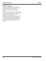
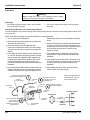
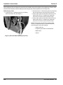
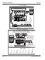
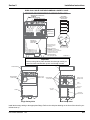
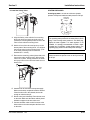
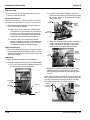
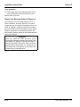
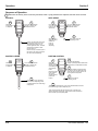
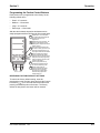
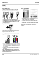
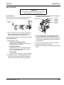
VARIETY VALVES
for Servend Beverage Dispensers
Installation, Use & Care Manual
This manual is updated as new information and models are released.
Visit our website for the latest manual. www.manitowocfsg.com
Leader in Ice & Beverage Dispensers
Part Number 020004001 4/12
Safety Notices
Read These Before Proceeding:
As you work on Manitowoc equipment, be sure to pay
close attention to the safety notices in this manual.
Disregarding the notices may lead to serious injury and/
or damage to the equipment.
Throughout this manual, you will see the following types
of safety notices:
! Warning
Text in a Warning box alerts you to a potential
personal injury situation. Be sure to read the
Warning statement before proceeding, and work
carefully.
! Caution
Text in a Caution box alerts you to a situation in
which you could damage the equipment. Be sure to
read the Caution statement before proceeding, and
work carefully.
! Caution
Proper installation, care and maintenance are
essential for maximum performance and troublefree operation of your Manitowoc equipment. Read
and understand this manual. It contains valuable
care and maintenance information. If you encounter
problems not covered by this manual, do not
proceed, contact Manitowoc Foodservice Group.
We will be happy to provide assistance.
Important
Routine adjustments and maintenance procedures
outlined in this manual are not covered by the
warranty.
! Warning
PERSONAL INJURY POTENTIAL
Procedural Notices
As you work on Manitowoc equipment, be sure to read
the procedural notices in this manual. These notices
supply helpful information which may assist you as you
work.
Do not operate equipment that has been misused,
abused, neglected, damaged, or altered/modified
from that of original manufactured specifications.
NOTE: SAVE THESE INSTRUCTIONS.
Throughout this manual, you will see the following types
of procedural notices:
Important
Text in an Important box provides you with
information that may help you perform a procedure
more efficiently. Disregarding this information will
not cause damage or injury, but it may slow you
down as you work.
NOTE: Text set off as a Note provides you with simple,
but useful, extra information about the procedure you
are performing.
We reserve the right to make product improvements at any time.
Specifications and design are subject to change without notice.
Section 1
General Information
Read This Manual . . . . . . . . . . . . . . . . . . . . . . . . . . . . . . . . . . . . . . . . . . . . . . . . .
1-1
Unit Inspection . . . . . . . . . . . . . . . . . . . . . . . . . . . . . . . . . . . . . . . . . . . . . . . . . . .
1-1
Model Numbers. . . . . . . . . . . . . . . . . . . . . . . . . . . . . . . . . . . . . . . . . . . . . . . . . . .
1-1
How To Read A Model Number . . . . . . . . . . . . . . . . . . . . . . . . . . . . . . . . .
1-1
Serial Number Location . . . . . . . . . . . . . . . . . . . . . . . . . . . . . . . . . . . . . . . . . . . .
1-1
Warranty Information . . . . . . . . . . . . . . . . . . . . . . . . . . . . . . . . . . . . . . . . . . . . . .
1-2
Section 2
Installation Instructions
General . . . . . . . . . . . . . . . . . . . . . . . . . . . . . . . . . . . . . . . . . . . . . . . . . . . . . . . . .
2-1
Specifications . . . . . . . . . . . . . . . . . . . . . . . . . . . . . . . . . . . . . . . . . . . . . . .
2-1
Electrical . . . . . . . . . . . . . . . . . . . . . . . . . . . . . . . . . . . . . . . . . . . . . . . . . . .
2-2
Plumbing . . . . . . . . . . . . . . . . . . . . . . . . . . . . . . . . . . . . . . . . . . . . . . . . . . .
2-3
Retrofit Installation . . . . . . . . . . . . . . . . . . . . . . . . . . . . . . . . . . . . . . . . . . .
2-10
System Pressures . . . . . . . . . . . . . . . . . . . . . . . . . . . . . . . . . . . . . . . . . . . .
2-13
ADA Key Pads . . . . . . . . . . . . . . . . . . . . . . . . . . . . . . . . . . . . . . . . . . . . . .
2-14
Starting Your Beverage System & Dispenser . . . . . . . . . . . . . . . . . . . . . . . . . .
2-16
General . . . . . . . . . . . . . . . . . . . . . . . . . . . . . . . . . . . . . . . . . . . . . . . . . . . . . . . . .
3-1
Sequence of Operation . . . . . . . . . . . . . . . . . . . . . . . . . . . . . . . . . . . . . . . . . . . .
3-2
Autofill . . . . . . . . . . . . . . . . . . . . . . . . . . . . . . . . . . . . . . . . . . . . . . . . . . . . .
3-2
Sanitary Lever . . . . . . . . . . . . . . . . . . . . . . . . . . . . . . . . . . . . . . . . . . . . . . .
3-2
Self-Serve . . . . . . . . . . . . . . . . . . . . . . . . . . . . . . . . . . . . . . . . . . . . . . . . . .
3-2
Portion Control . . . . . . . . . . . . . . . . . . . . . . . . . . . . . . . . . . . . . . . . . . . . . .
3-2
Programming the Portion Control Buttons . . . . . . . . . . . . . . . . . . . . . . . . . . . .
3-3
Restoring Factory Default Settings . . . . . . . . . . . . . . . . . . . . . . . . . . . . . . .
3-3
Cleaning. . . . . . . . . . . . . . . . . . . . . . . . . . . . . . . . . . . . . . . . . . . . . . . . . . . . . . . . .
4-1
How To Replace The Front Cover . . . . . . . . . . . . . . . . . . . . . . . . . . . . . . . . . . . .
4-1
Mounting Block. . . . . . . . . . . . . . . . . . . . . . . . . . . . . . . . . . . . . . . . . . . . . . . . . . .
4-2
Removing A Valve . . . . . . . . . . . . . . . . . . . . . . . . . . . . . . . . . . . . . . . . . . .
4-2
Installing A Valve . . . . . . . . . . . . . . . . . . . . . . . . . . . . . . . . . . . . . . . . . . . .
4-2
Section 3
Operation
Section 4
Maintenance
Table of Contents (continued)
Flow Controls . . . . . . . . . . . . . . . . . . . . . . . . . . . . . . . . . . . . . . . . . . . . . . . . . . . .
4-3
Change The Solenoid Or The Flow Control . . . . . . . . . . . . . . . . . . . . . . . .
4-3
Brixing . . . . . . . . . . . . . . . . . . . . . . . . . . . . . . . . . . . . . . . . . . . . . . . . . . . . . . . . . .
4-4
Brix Check . . . . . . . . . . . . . . . . . . . . . . . . . . . . . . . . . . . . . . . . . . . . . . . . . .
4-4
Brix Adjustment . . . . . . . . . . . . . . . . . . . . . . . . . . . . . . . . . . . . . . . . . . . . . .
4-5
Checklist . . . . . . . . . . . . . . . . . . . . . . . . . . . . . . . . . . . . . . . . . . . . . . . . . . . . . . . .
5-1
Section 5
Before Calling for Service
2
Part Number 020004001
4/12
Section 1
General Information
Section 1
General Information
Read This Manual
Model Numbers
Manitowoc Beverage Equipment (MBE) developed this
manual as a reference guide for the owner/operator and
installer of this equipment. Please read this manual
before installation or operation of the machine. A
qualified service technician must perform installation and
start-up of this equipment, consult Section 5 within this
manual for service assistance.
This manual covers the following models:
If you cannot correct the service problem, call your MBE
Service Agent or Distributor. Always have your model
and serial number available when you call.
Your Service Agent ____________________________
Beverage/Ice Dispensers
IC-2323, SV-150, SV-175, SV-200, SV-250, MDH-302, CEV30, CEV-40, CT-6, DI/DIL-2323
Variety Valves
AUTOFILL VALVE - 27-3102, SANITARY LEVER VALVE 27-3105, PUSH BUTTON VALVE - 27-3104, PORTION
CONTROL VALVE - 27-3103
HOW TO READ A MODEL NUMBER
Service Agent Telephone Number _________________
Model Base
Your Local MBE Distributor ______________________
Model Prefix
Distributor Telephone Number ____________________
Model Number _______________________________
MDH–302–i
Serial Number ________________________________
Installation Date ______________________________
Unit Inspection
Thoroughly inspect the unit upon delivery. Immediately
report any damage that occurred during transportation to
the delivery carrier. Request a written inspection report
from a claims inspector to document any necessary
claim.
Model Suffix
S = Ice Only
SV = Ice/Beverage
NGF = Ice/Beverage
FRP = Ice/Beverage &
Integrated Flavor Shots
Ice Capacity
i = Intellicarb
CI = Ice Crusher (IcePic)
SCI = Selectable
Crushed Ice
Serial Number Location
This number is required when requesting information
from your local distributor. The serial number is listed on
the SERIAL NUMBER DECAL affixed to the dispenser.
! Warning
PERSONAL INJURY POTENTIAL
Do not operate equipment that has been misused,
abused, neglected, damaged, or altered/modified
from that of original manufactured specifications.
Label
Serial Number Location
Part Number 020004001 4/12
1-1
General Information
Section 1
Warranty Information
Consult your local MBE Distributor for terms and
conditions of your warranty. Your warranty specifically
excludes all beverage valve brixing, general
adjustments, cleaning, accessories and related
servicing.
Your warranty card must be returned to MBE to activate
the warranty on this equipment. If a warranty card is not
returned, the warranty period can begin when the
equipment leaves the MBE factory.
No equipment may be returned to MBE without a written
Return Materials Authorization (RMA). Equipment
returned without an RMA will be refused at MBE’s dock
and returned to the sender at the sender’s expense.
Please contact your local MBE distributor for return
procedures.
1-2
Part Number 020004001
4/12
Section 2
Installation Instructions
General
These instructions are provided to assist the qualified installer. Contact your Manitowoc Beverage Equipment Service
Agent or call Manitowoc Beverage Equipment for information regarding start-up services.
Important
READ THIS BEFORE INSTALLATION
Failure to follow these installation guidelines may
affect warranty coverage.
SPECIFICATIONS
Valve height
5.45 in (13.8 cm)
Valve width
2.50 in (6.4 cm)
Valve depth
5.72 in (14.5 cm)
Operating temperature range
32–140 °F (0–60 °C)
Operational relative humidity range
20–100%
Electrical rating
24 VAC
Static water pressure
40–60 psig
Static syrup pressure
60 psig
CO2 pressure
70-75 psig
5.45 in
(13.8 cm)
10.84 in
(27.5 cm)
2.50 in
(6.4 cm)
Part Number 020004001 4/12
5.72 in
(14.5 cm)
2-1
Installation Instructions
Section 2
ELECTRICAL
! Warning
Always unplug the power to the dispenser before making
changes to the electrical wiring in the dispenser.
Grounding
•
All fountain equipment with a Variety valve installed
must be properly grounded.
•
The 24 VAC valve power supply must be properly
grounded.
Grounding The Dispenser For Autofill Variety Valves
For proper operation of the Autofill Variety valve, follow the steps below to determine if the existing Optifill valves need
to be grounded.
NOTE: These steps are usually only need to be followed on retrofit applications.
install the grounding wire on the transformer as shown
below.
1. Turn on the power to the dispenser.
2. Disconnect the 24V power supply from an Optifill valve
adjacent to the Variety valve.
6. After the grounding wire is installed, plug the dispenser
in and turn on the power. Recheck the voltage across
the white wire of the connector to the dispenser chassis
and across the black wire of the connector to the
dispenser chassis.
3. Check the voltage across the white wire of the
connector to the dispenser chassis. Check the voltage
across the black wire of the connector to the dispenser
chassis.
7. If the voltage across the white wire to the dispenser
chassis is 24-27 volts, proceed with the Variety valve
installation.
4. If the voltage across the white wire to the chassis is 2427 volts, the transformer is properly grounded. Proceed
with the Variety valve installation. If the voltage across
the black wire to the dispenser chassis is 24-27 volts,
reverse the load wires connected to the valve wire
harness as shown below and proceed with Variety valve
installation.
8. If the voltage across the black wire to the chassis is 2427 volts, reverse the load wires connected to the valve
wire harness and then proceed with Variety valve
installation.
9. After installing the Variety valve, check all valves to
make sure they all function properly.
5. If the voltage across either the white or black wires to the
chassis is less than 24 volts, a grounding wire must be
installed on the transformer. Unplug the dispenser and
Disconnect the hot load wire
(located below the black line wire).
EXISITING
CHASIS SCREW
GROUNDING
WIRE
LOAD WIRE,
HOT
PIGGYBACK
CONNECTOR
NOTE: The appearance of
the transformer may vary
from that shown here.
Connect the hot load wire to
the piggyback connector on
the grounding wire.
Connect the grounding
wire 4 to the transformer.
LINE WIRE,
BLACK
LINE WIRE,
WHITE
VALVE WIRE HARNESS
TRANSFORMER
Screw the grounding wire
to the chassis. (The
position or side of the
transformer may vary from
that shown here.)
2-2
LOAD WIRE,
NEUTRAL
TRANSFORMER
BRACKET
LOAD
REVERSE
CONNECTION
Part Number 020004001
4/12
Section 2
Installation Instructions
PLUMBING
Variety Valve Front View
90° Dole
FItting Long
Plain Water,
From Cold
Plate
1/4”Tubing
1/4” Tubing
Additional NonChilled Syrup
90° Dole
FItting Long
Chilled
Syrup, From
Cold Plate
Additional
Non-Chilled
Syrup
Additional
Non-Chilled
Syrup
1/4” Tubing with
Insulation Chilled
Syrup, From
Cold Plate
90° Dole FItting
Short
90° Dole FItting
Short
1/4”Tubing
1/4” Tubing with
Insulation Plain Water,
From Cold Plate
90° Bend
1/4” x 1/4”
90° Bend
1/4” x 1/4”
1/4” Tubing Additional
Non-Chilled Syrup
Mounting Block
Syrup 1
Syrup 3
Syrup 3
Flow Control
Syrup 1
Flow Control
Syrup 2
Flow Control
Water
Flow Control
Syrup 3
Syrup 2 Solenoid
Yellow Wires
Water Solenoid
Red Wires
Water
Syrup 2
Front View
Part Number 020004001 4/12
Syrup 3 Solenoid
Blue Wires
Syrup 1 Solenoid
Brown Wires
Top View
Syrup 2
Syrup 1
Key Pad
2-3
Installation Instructions
Section 2
When Installing the Servend dispenser please follow the installation instructions supplied in the Installation and Service Guide.
Also follow the instructions below for finding and connecting the two ambient syrup lines for the Variety Valve.
Ambient Syrup Lines
1. Locate the two ¼” ambient syrup lines for Variety
Valve flavors #2 & #3. (See Figure 1)
2. Access the two ¼” ambient syrup lines by removing
the tie strap used to secure the lines to the unit.
3. Connect the syrup line that will be flavor #2 on the
Variety Valve to the ¼” ambient line marked #2.
Secure the connection with an Oetiker Clamp.
4. Connect the syrup line that will be flavor #3 on the
Variety Valve to the ¼” ambient line marked #3.
Secure the connection with an Oetiker Clamp.
NOTE: Please refer to the McCann’s Variety Valve
manual or contact McCann’s at 1-800-423-2429 for
more information about the following:
- Setting valve brix
- Programing the Portion Control Buttons
- Maintenance
- Service
Figure 1 (Flavor #2 & #3 Ambient Syrup Lines)
2-4
Part Number 020004001
4/12
Section 2
Installation Instructions
IC-2323 8 VALVE DIAGRAM
SYRUP LINES 2 & 3 WILL CONNECT
TO BIB ON THE BACK OF THE UNIT
RECOMMENDED PLUMBING IC2323
(WITH #6 VARIETY VALVE)
NOTES:
A. VALVES 1, 2, 7, 8 PERMANENTLY CARBONATED.
CONNECTED TO CARB WATER CIRCUIT.
B. PLAIN WATER TO FLEX MANIFOLD.
C. PLAIN WATER TO THE CARBONATOR.
D. CARB WATER TO COLDPLATE POST-CHILL.
1-SYRUP
(THRU COLD PLATE)
2-SYRUP
(AMBIENT)
3-SYRUP
VALVES 3, 4, 5, 6
PLUMBED TO THE FLEX MANIFOLD.
(AMBIENT)
POST-CHILL
OUT
2-1-1-1-1-2 FLEX
RIGHT TO LEFT
4-WATER
NOT IN USE
(THRU COLD PLATE)
PLAIN WATER OUT
FLEX
MANIFOLD
PLAIN WATER OUT
POST-CHILL OUT
MANIFOLD : CHANGE TO CARBONATED OR
NON-CARBONATED WATER
1. ROTATE PLUNGER 180O USING A 5/32” ALLEN WRENCH
2. PULL PLUNGER UP TO GET NON-CARBONATED WATER
3. PUSH PLUNGER DOWN TO GET CARB WATER
4. TURN PLUNGER BACK 180O TO LOCK
POST-CHILL IN
PRE-CHILL OUT
FOR ASSISTANCE
CALL (812) 246-7000
FROM PUMP
5031148-0
SV-150 6 VALVE DIAGRAM
PLUMBING: 2-1-1-2 MANIFOLDING
*OPTIONAL*
VARIETY VALVE ON #3
INTERNAL CARBONATOR TANK
1-WATER
(THRU COLD PLATE)
VALVES “SYRUP LINES NOT SHOWN”
CO2
2-SYRUP
(AMBIENT)
3 -SYRUP
(AMBIENT)
SYRUP #2
MANIFOLD : CHANGE TO CARBONATED OR
NON-CARBONATED WATER
1. ROTATE PLUNGER 180O USING A 5/32” ALLEN WRENCH
2. PULL PLUNGER UP TO GET NON-CARBONATED WATER
3. PUSH PLUNGER DOWN TO GET CARB WATER
4. TURN PLUNGER BACK 180O TO LOCK
5. PORT 5 IS NOT USED
SYRUP
#3 - VA
RIETY
VLV PO
SYRUP #4
SITION
-4
SYRUP #5
SYRUP #6
PLAIN WATER
- FROM WAT
ER SUPPLY
PLAIN WATER
- FROM
TO CARBONA PUMP
TOR
CIRCUITS
SYRUP #1
CARBONATOR OUT TO POST-CHILL
PRE-CHILL OUT TO CARBONATOR
4-SYRUP
(THRU COLD PLATE)
VALVES
COLD PLATE
* EXTERNALLY CARBONATED UNITS: CARBONATOR IS REPLACED BY A BY-PASS TUBE
FOR ASSISTANCE CALL (812) 246-7000
020000254-1
Part Number 020004001 4/12
2-5
Installation Instructions
Section 2
SV 8 VALVE DIAGRAM
PLUMBING: 3-1-1-1-2 MANIFOLDING
*OPTIONAL*
VARIETY VALVE ON #4
INTERNAL CARBONATOR TANK (OPTIONAL)
1-WATER
(THRU COLD PLATE)
VALVES “SYRUP LINES NOT SHOWN”
2-SYRUP
CO2
(AMBIENT)
3 -SYRUP
(AMBIENT)
(THRU COLD PLATE)
CARBONATOR OUT TO POST-CHILL
VALVES
FROM WAT
ER SUPPLY
PLAIN WATER
- FROM PUM
P
TO CARBON
ATOR
SYRUP #8
PLAIN WATER
-
SYRUP #5
SYRUP #6
SYRUP #7
SYRUP #3
SYRUP #4 4
SYRUP #1
CIRCUITS
SYRUP #2
PRE-CHILL OUT TO CARBONATOR
4-SYRUP
COLD PLATE
* EXTERNALLY CARBONATED UNITS: CARBONATOR IS REPLACED BY A BY-PASS TUBE
FOR ASSISTANCE CALL (812) 246-7000
5029871-2
MDH-302 12 VALVE DIAGRAM
PART
#5011803-1
MDH-302 RIGHT HAND SIDE
SERVEND RECOMMENDED PLUMBING
2-1-1-2 FLEX
LEFT TO RIGHT
*OPTIONAL*
VARIETY VALVE ON #3
1-WATER
INTERNALLY CARBONATED UNITS:
A. PLAIN WATER TO THE CARBONATOR
B. CARB WATER FROM INTERNAL
CARBONATOR TO FLEX-MANIFOLD
C. PLAIN WATER TO FLEX-MANIFOLD
(THRU COLD PLATE)
2-SYRUP
(AMBIENT)
POST-CHILL
3 -SYRUP
(AMBIENT)
4-SYRUP
FLEX-MANIFOLD
(THRU COLD PLATE)
IN
OUT
INTERNAL
CARBONATOR
TANK
PRE-CHILL
FOR ASSISTANCE
CALL (812) 246-7000
NOTE: SYRUP LINES NOT SHOWN
* EXTERNALLY CARBONATED UNITS:
CARBONATOR IS REPLACED BY
A BY-PASS TUBE
2-6
PLAIN
WATE
(C)
R
SYRU
P #6
SYRU
P #5
SYRU
P #4
SYRUP
#3 VARIET
Y VLV
SYRU
P #2
SYRU
P #1
INLET LINES
CARB
SEE WATER
NOTE
(A)
NOTE: INTERNALLY CARBONATED UNITS - FROM CARBONATOR PUMP TO CARBONATOR LOCATED ON UNIT
EXTERNALLY CARBONATED UNITS - FROM EXTERNAL CARBONATOR TO MANIFOLD
Part Number 020004001
4/12
Section 2
Installation Instructions
CEV-30 6 VALVE DIAGRAM
SERVEND RECOMMENDED PLUMBING
ALL INLETS ARE 3/8” BARBED FITTINGS EXCEPT CO2 INLET
CEV-30i & CEV-30e
*OPTIONAL*
VARIETY VALVE ON #3
1-WATER
(SEE VALVE 3)
VALVE #3
2-SYRUP
VALVE #3
(AMBIENT SEE VALVE 3)
3 -SYRUP
(AMBIENT SEE VALVE 3)
4-SYRUP
#3 AMBIENT
SYRUP ON
VARIETY VALVE
OPTION
#2 AMBIENT
SYRUP ON
VARIETY VALVE
OPTION
CARB
WATER
INLET
#2 AMBIENT
SYRUP ON
VARIETY VALVE
OPTION
PLAIN WATER INLET
SYRUP 6
SYRUP 5
SYRUP 4
SYRUP 3
CHECK VALVE
(FLOW ARROW
POINTS INTO WATER LINE)
SYRUP 2
SYRUP 1
SYRUP 6
SYRUP 5
CO2 INLET
SYRUP 4
SYRUP 3
SYRUP 2
SYRUP 1
(THRU ICE BATH SEE VALVE 3)
#3 AMBIENT
SYRUP ON
VARIETY VALVE
OPTION
CARB
WATER
INLET
PLAIN WATER INLET
INTERNAL CARBONATION
EXTERNAL CARBONATION
NOTES:
1. ALL VALVES ARE CARBONATED WATER AS SHIPPED FROM FACTORY
2. CHECK VALVE SUPPLIED WITH UNIT IS INSTALLED IN THE NON-CARBONATED WATER LINE INLET. THE FLOW DIRECTION ARROW SHOULD POINT INTO THE STAINLESS STEEL LINE
3. NUMBER 6 VALVE AWAYS CARBONATED
020001226-0
CEV-40 8 VALVE DIAGRAM
SERVEND RECOMMENDED PLUMBING
ALL INLETS ARE 3/8” BARBED FITTINGS EXCEPT CO2 INLET
CEV-40i & CEV-40e
#3-2
AMBIENT
SYRUP
NON-CARB WATER INLET
INTERNAL CARBONATION
VALVE #2
VALVE #3
CHECK VALVE
(FLOW ARROW
POINTS INTO WATER LINE)
#2-1
AMBIENT
SYRUP
#2-2
AMBIENT
SYRUP
#3-1
AMBIENT
SYRUP
#3-2
AMBIENT
SYRUP
SYRUP 8
1-SYRUP
(#3-1 AMBIENT)
SYRUP 7
1-SYRUP
(#2-1 AMBIENT)
SYRUP 6
2 -SYRUP
(#3-2 AMBIENT)
SYRUP 5
2 -SYRUP
(#2-2 AMBIENT)
SYRUP 4
3-SYRUP
(THRU ICE BATH )
SYRUP 3
3-SYRUP
(THRU ICE BATH )
SYRUP 2
1-WATER
SYRUP 1
SYRUP 6
SYRUP 5
SYRUP 4
#3-1
AMBIENT
SYRUP
1-WATER
CARB WATER INLET
#2-2
AMBIENT
SYRUP
SYRUP 7
CO2 INLET
PLAIN WATER INLET
SYRUP 8
#2-1
AMBIENT
SYRUP
SYRUP 3
SYRUP 2
SYRUP 1
VARIETY VALVE
BLOCK
NON-CARB WATER INLET
EXTERNAL CARBONATION
NOTES:
1. ALL VALVES ARE CARBONATED WATER AS SHIPPED FROM FACTORY
2. VALVE NUMBER 6 ,7, & 8 AWAYS CARBONATED
3. CHECK VALVE SUPPLIED WITH UNIT IS INSTALLED IN THE NON-CARBONATED WATER LINE INLET. THE FLOW DIRECTION ARROW SHOULD POINT INTO THE STAINLESS STEEL LINE
020002740-0
Part Number 020004001 4/12
2-7
Installation Instructions
Section 2
CT-6, 6 VALVE DIAGRAM
CT-6 RECOMMENDED PLUMBING
2-1-1-2 PLUMBING CONFIGUREATION
*OPTIONAL*
VARIETY VALVE
ON VALVE 4
CAUTION
ELECTRICAL SHOCK HAZARD
DISCONNECT POWER BEFORE SERVICING
CT-6 WIRING DIAGRAM
W-WATER
(THRU COLD PLATE)
3-SYRUP
(#4-3 AMBIENT)
2-SYRUP
(#4-2 THRU COLD PLATE)
1-SYRUP
(#4-2 AMBIENT)
020003552-0
2-8
UNIT DRAIN
CARB. OR PLAIN WATER 4
SYRUP 4-1
SYRUP 4-2
SYRUP 4-3
SYRUP 5
CARB. OR PLAIN WATER 5 & 6
SYRUP 6
SYRUP 3
SYRUP 2
CARB. OR PLAIN WATER 3
SYRUP 1
CARB. OR PLAIN WATER 1 & 2
VARIETY VALVE
BLOCK
LIGHTER MERCH.
POWER CORD
VALVE JUMPER
HARNESS
POWER CORD
COUNTER
TOP
ELECTRICAL BOX
Part Number 020004001
4/12
Section 2
Installation Instructions
DI/DIL-2323 8 VALVE POST-MIX PLUMBING & VARIETY VALVE
SERVEND RECOMMENDED PLUMBING DI/DIL-2323
*OPTIONAL DUAL FLAVOR VALVE*
8A AMBIENT
8B THRU COLD PLATE
*OPTIONAL*
VARIETY VALVE
ON VALVE 6
OPTIONAL VARIETY VALVE
1-WATER
(THRU COLD PLATE)
2-SYRUP
(AMBIENT)
3-SYRUP
WATER 1
SYRUP 1
WATER 2
SYRUP 2
WATER 3
SYRUP 3
WATER 4
SYRUP 4
WATER 5
SYRUP 5
WATER 6
SYRUP 6
WATER 7
SYRUP 7
WATER 8
SYRUP 8 (B)
(AMBIENT)
RELIEF VALVE
4-SYRUP
CO2 TO
CARBONATOR
(THRU COLD PLATE)
CARBONATOR
CARBONATED WATER CIRCUIT (A)
PLAIN WATER CIRCUIT (B)
SYRUP 8 (B)
SYRUP 7
SYRUP 6
SYRUP 5
SYRUP 4
SYRUP 3
SYRUP 2
SYRUP 1
3/4” NPT
DRAIN PAN
DRAIN
3/4” NPT
COLD PLATE
DRAIN
INTERNALLY
CARBONATED
UNITS ONLY
SYRUP 8 (A)
CO2 IN
WATER 7, 8
WATER 6
WATER 5
WATER 4
WATER 1, 2, 3
AMBIENT CARBONATION:
A. CARBONATED WATER
B. PLAIN WATER
BOTTOM VIEW
INTERNAL CARBONATION:
A. PLAIN WATER TO CARBONATOR
FROM PUMP
B. PLAIN WATER (40-55 PSI) TO MANIFOLD
C. CARBONATED WATER FROM
CARBONATOR TO MANIFOLD
FOR ASSISTANCE
CALL (812) 246-7000
020001191-1
Important
Before routing Variety Valve ambient lines through conduit you
must first route merchandiser power cord through conduit.
MERCHANDISER
MERCHANDISER
VARIETY VALVE
ABMIENT LINES
MERCHANDISER
POWER CORD
MERCHANDISER
POWER CORD
LINES
6-1 & 6-3
VARIETY VALVE
ABMIENT LINES
LINES
5-1 & 5-3
RIGHT SIDE
CONDUIT
LEFT SIDE
CONDUIT
CONDUIT
CARB PUMP
MOTOR CORD
Single Variety Valve
Dual Variety Valve
Install the beverage tubing to the appropriate fittings. Refer to the cold plate drawing on the front of the chest for your
individual set up.
Part Number 020004001 4/12
2-9
Installation Instructions
Section 2
RETROFIT INSTALLATION
The Variety valve may be retrofitted to nearly any softplumbed fountain dispenser.
1. Inspect the Variety Valve
Thoroughly inspect the Variety valve upon delivery.
Immediately report any damage that occurred during
transportation to the delivery carrier. Request a written
inspection report from a claims inspector to document any
necessary claim. Make sure the following components are
available to install the valve:
Component
Quantity
Variety valve
1
Mounting block
1
Retrofit plate kit
1
90° short dole fitting
2
90° long dole fitting
2
90° bends
2
Installation and service manual
1
3/8 in × 1/4 in splicer
2
Oetiker clamps (13.3 mm or 11.3 mm)*
8
Sheet metal screws
4
NOTE: A knockout tool is required for installation and is
not provided with the Variety valve.
2. Prepare the Site
A. Make sure the following equipment/supplies are
available before starting the installation:
Quantity
BIB pumps (Shurflo pumps are
recommended)
2
BIB connectors
2
Space for 2 extra BIB bags or an additional
BIB rack
• Too high—If the plain water pressure is ≥60 psig,
install a pressure regulator in the back room
where the plain water line branches out.
• Too low—Use one of the following methods to
check for low water pressure:
- Open the plain water valve and a carbonated
water valve at the same time. When the
carbonator pump turns on, read the pressure
gauge. If the pressure is <35 psig, a dedicated
plain water line is necessary.
- If a pressure gauge is not available, open the
existing plain water valve and note the amount
of water flowing. Open a carbonated water
valve until the carbonator pump turns on.
Check the plain water flow again. If the water
flow is greatly reduced, plan for a dedicated
plain water line from the back room to the
Variety valve.
*Size depends on tubing brand. Always use the
manufacturer’s recommended hose clamp size.
Component
B. Verify the plain water pressure is not too high or
too low.
NOTE: Make sure that high
movers are placed on the lower
section of the rack.
C. Run new syrup lines from the back room to the
dispenser.
• If the existing syrup lines are underground and 2
extra lines are not available in the current tube
bundle, run a new tube bundle.
• If the existing syrup lines are in the ceiling, run 2
new lines beside the existing lines.
D. D. For carbonated water drink set up, check
access to carbonated water line or carbonator.
3. Remove the Existing Valve
! Caution
Use safety glasses during the installation.
3/8 in BIB tubing
As needed
3/8 in standard beverage line for non-chilled
syrup (Bev-Ultra Seal)
As needed
A. Unplug the power supply to the unit.
1/4 in flexible tubing
As needed
B. Depressurize the water and syrup BIB. Flush all
lines of all syrup and water.
Socket wrench
1
1 1/8 in socket
1
Phillips screwdriver
1
Safety glasses
1
Alcohol wipes or rubbing alcohol
As needed
Oetiker pliers
1
Tube cutter
1
UF-1 syrup separator
1
Pepsi brix cup
1
Food grade lubricant
Knockout tool kit
2-10
C. Gain access to the back of the mounting plate.
For drop-in dispensers, remove the splash plate.
For ice-drink units, remove the splash plate and
if needed, remove the ice chute.
As needed
1
Part Number 020004001
4/12
Section 2
Installation Instructions
D. Remove the existing plain water valve and
mounting block from the dispenser. Remove 3
adjacent valves to provide more working space.
C. Hold the rear support die behind the mounting plate
so that the 4 holes on the die are aligned with the
mounting plate holes. Make sure the label on each
piece of the knockout tool is facing up.
SIDE VIEW
NOTE: The actual position of the Variety valve on the unit may vary from that
shown in the illustration.
E. Remove the inlet water and syrup fittings from
the mounting plate. If the fittings are foamed in
place, remove the foam to access the fittings.
Push the 24 volt connector and wires to the
back of the mounting plate.
4. Install the Retrofit Mounting Plate
C
NOTE: Make sure the 24 volt
connector and wires are routed
through the wire chase on the front
barrel die.
D. Place the front barrel die against the mounting
plate aligning the cap screws with the mounting
plate holes. Tighten each of the 4 cap screws
with the included hex key.
A. Apply the grease that is included in the tool kit to
the tip and the threads of the bolt and to the
sides and back of the punch before each use.
D
A
Cap Screws
E
Bolt
Front
Barrel Die
Knockout
Punch
Rear
Support Die
Knockout Tool Kit
NOTE: Included but not shown: additional cap screws (4), hex key, grease
B. Load the knockout punch (cutting part) into the front
barrel die. Make sure the bolt is backed out enough
to allow the points of the knockout punch to be fully
enclosed in the front barrel die so that the front
barrel die will lay flush against the mounting plate.
B
To ensure the cap screws are properly
tightened, tighten each cap screw until its head
bottoms out on the face of the front punch
barrel, and tighten an additional 1/2 turn.
Recheck the tightness of each cap screw, and
retighten if necessary.
Important
Make sure each of the 4 cap screws are securely
tightened prior to proceeding. If all 4 screws are not
tightened properly, the tool may not operate
correctly and damage to the tool may occur.
E. Use a socket wrench to turn the bolt clockwise
until the knockout punch completely breaks
through the mounting plate.
F. Remove the entire knockout tool and dispose of
the piece punched out of the mounting plate.
Part Number 020004001 4/12
2-11
Installation Instructions
Section 2
6. Install the Mounting Block
5. Create New Lines
! Caution
Use safety glasses during the installation.
A. Use a 90° short fitting, 1/4 inch tubing, and
insulation from the existing PLAIN water line or
CARBONATED water line.
REAR VIEW
E
90° Long Fitting
Oetiker Clamp
(13.3 mm)
90° Long Fitting
A
B
A. Remove the front and rear covers from the
Variety valve. Remove the 4 screws from the
retrofit mounting plate.
B. Align all 4 inlet fittings with the mounting block
inlet holes. Use any food-grade lubricant on the
O-rings as needed.
C. Use the existing screws to tighten the mounting
block to the mounting plate. If the screws are not
long enough, use the screws provided in the
retrofit kit.
C
SYRUP #1
PLAIN OR
CARBONATED
WATER
SYRUP #3
SYRUP #2
7. Splice the Lines
Non-chilled Syrup Line From
Mounting Plate
D
NOTE: Do not use the screws in the retrofit kit
on drop-in units.
A
B
C
D
Oetiker Clamp
B. Create a new SYRUP LINE (Syrup #2) using a
90° short fitting and 1/4 inch tubing.
C. Create the CHILLED SYRUP LINE (Syrup #3)
using a 90° long fitting, 1/4 inch tubing, and the
insulation from existing chilled syrup line.
D. Create another new SYRUP LINE (Syrup #1)
using a 90° long fitting and 1/4 inch tubing.
1/4 inch Tubing
A. Trim the length of the additional non-chilled
syrup lines as necessary to route the tubing
under the dispenser.
B. Use a 90° bend to route the tubing under the
dispenser.
C. Use 1/4 inch tubing to run the additional nonchilled syrup lines to the respective 3/8 inch BIB
tubing. Trim the length of the 1/4 inch tubing as
necessary.
D. Use the 1/4 inch × 3/8 inch splicer to connect
the non-chilled syrup line to the BIB tubing.
E. Connect the water and chilled syrup lines to the
cold plate and trim the length as necessary.
2-12
Part Number 020004001
4/12
Section 2
Installation Instructions
SYSTEM PRESSURES
8. Install the Variety Valve
Incoming tap water - must be at a minimum dynamic
pressure of 40 psi and maximum static pressure of 60 psi.
A
Operating
Pressure
Range
Mounting Block
Inlet Holes
A. Align the Variety valve with the four mounting
block inlet holes and gently push the valve in
(toward the mounting block) until the back of the
valve is flush with the mounting block.
B. Hold the front of the valve and push up on the
bottom plate of the mounting block. You will hear
the locking sound on the mounting block. (This
is the same mounting method used with
standard UF-1 valves.)
C. Remount the remaining valves (those that were
removed to make working room). When all the
valves are in place, slowly pressurize the water
and syrup lines one at a time and make sure no
leaks occur.
Important
The operating water pressure for the Variety Valve is 40-60
psig. If the incoming water pressure is not 40-60 psig,
adjust the water regulator. If a water regulator is not
installed, it is strongly recommended to install a water
regulator and, if necessary, a water booster system. The
operating syrup pressure for the Variety Valve is 60 psig
Important
Water boosters are preset to turn on at 65 psi and off
at 85 psi.
D
Ribbon
Cable
Wire Channel
Tab
D. Attach the 24 volt connector to the power supply.
Make sure the wires are placed inside the channel.
If the wires do not fit in the channel, trim the tab
enough to make the wires fit.
E. Brix the valve (see Valve Brix). Place the rear cover
on the valve. Make sure the ribbon cable is placed
behind the support on the rear valve cover.
F. Connect the ribbon cable on the front cover to the
ribbon cable on the valve and place the front cover
on the valve.
Part Number 020004001 4/12
2-13
Installation Instructions
Section 2
ADA KEY PADS
These instructions are for installations with this option.
1. Remove power from the unit.
Merchandiser Removal
NOTE: Not necessary on CEV units, ADA connections
are made below the valve mount cap on these models.
B. SV & SVi units, continue routing the ADA cable
behind the valve mount cap on the left hand side of
the unit and connect to the ADA harness clipped
to the foam front.
ADA
Harness
2. Gain access to the merchandiser area of the dispenser
by one of the following methods;
A. MDH Series units, remove the medallion from
merchandiser to gain access to the area above
the valve mount cap. Medallions are removed
through the top of standard merchandisers and
either side of the extended merchandisers.
B. SV & SVi Series units, loosen the two knurled
fasteners located in the top of the merchandiser that
hold the merchandiser in place. Then remove the
merchandiser by lifting up and tilting forward.
Splash Panel Removal
3. Remove the splash panel from the unit by removing the
two (2) phillips head screws holding it in place. On CEV
units remove the drain pan to gain access to the two (2)
splash panel screws.
ADA Box
Ribbon
Connector
ADA Box
Ribbon Cable
C. MDH units locate the ADA harness, on units with a
crusher it will be on the left of the ice chute, noncrusher units will be on the right. Connect to the
ADA harness that is clipped to the foam front.
ADA
Harness
ADA Box
Ribbon
Connector
ADA Wiring
Valve
Mount Cap
4. Route the ADA ribbon cable under the drain pan.
5. Continue routing the ADA cable up to the ADA harness;
A. CEV units, ADA harness is clipped to the wall of
the CEV below the valve mount cap.
6. Neatly tuck in and take up any slack remaining in the
ADA ribbon cable so it will not be in the way of any
moving parts or panels when they are placed back on
the unit.
NOTE: Units that also have ADA for beverage valves will
have 2 harness connections, one for the beverage ADA
Key Pad Box and one for the Variety Valve ADA Box.
The Variety Valve uses the smaller connector.
Internal ADA
Harness
ADA Ribbon
Cable
Drain Pan
ADA Box
2-14
Beverage
Valve ADA
Connector
Variety
Valve ADA
Connector
Harness
Clip
Part Number 020004001
4/12
Section 2
Installation Instructions
ADA Key Pad Matrix
Drain Pan & ADA Touch Pad Box
7. Attach the drain pan to the unit.
1
2
3
4
8. Center the ADA Key Pad Box (or Boxes if more than will
be used) with the unit in front of the drain pan and
secure into place.
1
2
3
4
4 Button Variety Valve
6 Valve Dispensers (1 Variety Valve)
Connected
ADA
Cables
1
Drain
3
4
5
6
ADA Box
1
2
3
4
5
6
7
8
9
10
6 Valve Dispensers (2 Variety Valves)
1
1
Important
If mounting the ADA Box directly in front of the drain pan
on the counter top leave a minimum of 1 inch space
between the bottom edge of the drain pan and the ADA
Box to allow space for drain pan removal. CEV units may
need more space for drain pan removal, mounting to the
front edge of the counter top may be necessary.
4
2
3
4
5
6
7
6
8
9
10
8 Valve Dispensers (1 Variety Valve)
1
9. Apply corresponding drink labels to the ADA key pads
using the ADA Key Pad Matrix.
3
1
NOTE: Variety Valve Drinks correspond from top to bottom on
the valve to left to right on ADA key pads. If buttons are not used
they will be blanked out.
2
3
4
4
5
5
6
6
7
7
8
9
8
10
8 Valve Dispensers (2 Variety Valve)
1
4
1
Part Number 020004001 4/12
5
2
3
4
5
5
6
6
7
7
8
9
8
10
2-15
Installation Instructions
Section 2
Finish Installation
10. Put the splash panel and merchandiser back onto the
unit and reinstall the screws that hold them in place.
Restore power to the unit.
Starting Your Beverage System & Dispenser
Upon completion of the beverage dispenser and / or
system installation, all tubing, dispenser, and system
components must be cleaned and sanitized prior to use.
NOTE: At installation, equipment, dispensers, and tubing
get moved through many environments, dirt, dust, chases,
insulation, drywall, etc. It is an important procedure and
best practice to address cleaning to deliver the best quality
drink to your customer.
Important
Clean and sanitize the water and syrup circuits
according to instructions provided in this manual. Clean
and sanitize the dispenser components according to
instructions provided in this manual. Seal to counter top
when no legs are used with the unit. Consult and use
local health codes if a discrepancy occurs between this
manual and your local health codes.
2-16
Part Number 020004001
4/12
Section 3
Operation
Section 3
Operation
General
This unit is equipped with a McCann’s Variety Valve. The Variety Valve is capable of dispensing three different flavors
of plain water beverages. Four models of the Variety Valve are available:
•
Autofill – The user places a cup against the
dispensing lever and the valve automatically
dispenses until liquid or foam touches the lever.
•
Self-serve – The user manually dispenses a
beverage by pressing the flavor button until the cup
is full.
•
Sanitary lever – The user manually dispenses a
beverage by pressing the cup against the dispensing
lever until the cup is full.
•
Portion control – The user selects the beverage
flavor and dispenses the beverage by pressing a preprogrammed portion size button.
NOTE: The Servend dispenser has been slightly modified to adapt to the 3-flavor Variety Valve. Please take time to
read the information in this Manual to familiarize yourself with installing the Servend dispenser equipped with the
Variety Valve.
Part Number 020004001 4/12
3-1
Operation
Section 3
Sequence of Operation
1 Make sure the Variety valve is securely mounted, water / syrup pressures are adjusted, and the valve is brixed.
SELF-SERVE
AUTOFILL
2
Select the
beverage flavor
to dispense.
3
3
4
One of the LED indicators
will light up showing the
flavor/water chosen.
Press and hold
one of the flavor
buttons or the
water button.
One of the LED indicators
will light up showing the
flavor/water chosen.
2
5
Place a cup against the lever under
the dispensing nozzle. The valve
starts dispensing when the cup
presses against the lever. The valve
will dispense until liquid or foam
touches the lever.
Place a cup under the
dispensing nozzle.
When the cup is
adequately filled,
release the
button to
terminate
dispensing.
NOTE: If the cup is removed prior to
the liquid or foam touching the lever,
the valve will stop dispensing.
SANITARY LEVER
PORTION CONTROL
2
3
Select the
beverage flavor
to dispense.
One of the LED indicators
will light up showing the
flavor/water chosen.
4
Press and hold a cup against the
lever under the dispensing nozzle
until the desired amount of beverage
is dispensed.
3
Select the
desired flavor or
water by pressing
and releasing the
corresponding
button.
NOTE: The water
button, labeled
with a W, is
located below the
portion size
buttons.
4
One of the LED indicators
will light up showing the flavor/water chosen.
NOTE: There is no LED indicator for water.
5
Press and release the desired portion
size button. The drink will dispense for
either the factory-set time period or for
the programmed time period.
2
Place a cup under the
dispensing nozzle.
6
To terminate a timed dispense cycle, press and RELEASE the Cancel/
Pour button during the timed dispense cycle.
To top off the beverage after the dispense cycle is complete or to
manually dispense the beverage, press and HOLD the Cancel/Pour
button until the cup is adequately filled.
3-2
Part Number 020004001
4/12
Section 3
Operation
Programming the Portion Control Buttons
Each portion size is programmed at the factory for the
following default times:
•
Small – 2.0 seconds
•
Medium – 3.0 seconds
•
Large – 4.0 seconds
•
Extra large – 6.0 seconds
After the valve is brixed, the portion size buttons can be
easily reprogrammed in the field from the front control panel.
5
Repeat steps 2–4 for each portion
size to be programmed. NOTE: Not
all portion sizes have to be
programmed.
4
Release the portion size button. The
program mode indicator will stop
flashing and the dispense time will be
stored to memory.
3
Press and hold the desired portion
size button until the proper amount of
beverage is dispensed into the cup.
The program mode indicator will flash.
1
Enter the programming mode by
pressing and holding the hidden
program button for 3 seconds without
interruption. When the programming
mode is entered, the program mode
indicator is illuminated.
Program
Mode
Indicator
2
6
Place the appropriate size cup
containing the desired amount of
ice under the dispensing nozzle.
Exit the program mode by
pressing and holding the hidden
program button for 3 seconds.
The most recent settings will be
saved and the program mode
indicator will turn off.
RESTORING FACTORY DEFAULT SETTINGS
To restore the factory default setting, enter the
programming mode and then press and hold the Cancel/
Pour button
for 3 seconds while at the same time
pressing the desired portion size button. The factory
default for that portion size button will be restored.
Part Number 020004001 4/12
3-3
Operation
Section 3
THIS PAGE INTENTIONALLY LEFT BLANK
3-4
Part Number 020004001
4/12
Section 4
Maintenance
Section 4
Maintenance
Cleaning
How To Replace The Front Cover
All cleaning must meet your local health department
regulations. The following cleaning instructions are
provided as a guide.
1. Remove the valve front cover by pushing it upward
and pulling it out away from the valve.
! Caution
Do not expose the front valve cover ribbon cable to water.
! Caution
Use only warm soapy water to clean the exterior of
the tower. Do not use solvents or other cleaning
agents. Do not pour hot coffee into the drain pan.
Pouring hot coffee down the drain pan can
eventually crack the drain pan, especially if the
drain pan is cold or still contains ice.
2. Disconnect the ribbon cable on the front valve cover
from the ribbon cable on the valve by pressing and
holding the latch.
! Warning
Electric Shock Hazard
Unplug unit before servicing or cleaning.
Diffuser
1
Mix warm (120 °F) water with mild
detergent.
2
Remove the nozzle assembly from
the dispensing valve. Separate the
diffuser from the nozzle
3
Wash the diffuser (black) and the
nozzle in the detergent solution.
4
Rinse the diffuser and nozzle in clean
water.
5
Reassemble the diffuser and
nozzle on the dispensing valve.
Nozzle
Part Number 020004001 4/12
3. Connect the ribbon cable on the new front valve
cover to ribbon cable on the valve.
4. Align the hooks on the front cover with the slots on
the rear cover and push the front cover in until it
snaps in place.
5. Press down on the front valve cover until it snaps
into place.
4-1
Maintenance
Section 4
Mounting Block
INSTALLING A VALVE
REMOVING A VALVE
! Warning
1
Electric Shock Hazard
Align the Variety valve with the four mounting block inlet holes
and gently push the valve in (toward the mounting block) until
the back of the valve is flush with the mounting block.
Unplug unit before servicing or cleaning.
2 While holding the tab, push down on the top
plate and pull the valve out.
2
1
To remove a valve from the mounting block,
pull the tab on the left-hand side out and hold.
! Caution
Hold the valve securely because pressure may cause the
valve to move outward slightly.
If the Variety valve is difficult to remove from the
mounting block:
Hold the front of the valve and push up on the bottom plate of the
mounting block. You will hear the locking sound on the mounting
block. (This is the same mounting method used with standard
UF-1 valves.)
If a leak occurs between the mounting block and the
Variety valve after mounting the valve on the mounting
block, remove the valve and inspect the mounting block
o-rings for damage. Replace any damaged o-rings.
Ensure that none of the o-rings are pinched when
placing the valve back onto the mounting block.
Inspect o-ring
for damage
1. Ensure the lower left clip is pressed to the left when
pushing down on the top plate of the mounting
block. DO NOT EXERT EXCESSIVE FORCE ON
THE CLIP.
2. When applying force to push down the mounting
block top plate, alternate where the force is applied
on the top plate; push down on the left side and then
the right. Repeat until the top is fully pushed down.
Alternate force between these two points
Press clip
4-2
Part Number 020004001
4/12
Section 4
Maintenance
Flow Controls
CHANGE THE SOLENOID OR THE FLOW CONTROL
If a flow control does not respond when turning the adjustment
screw or if there is difficulty in brixing the valve, remove the
flow control’s ceramic cylinder and ceramic piston. Remove
the piston from the cylinder. Inspect for and remove any debris
and clean the piston and cylinder with warm water.
Reassemble the piston and cylinder into the valve.
NOTE: To change the flow control, follow steps 1–5. To
change the solenoid, follow steps 1, 2, and 6–8.
1. Depressurize all of the water and syrup lines.
2. Remove the front valve cover. Remove the rear valve
cover. Unplug the power supply. If necessary, remove
the valve from the unit to make room to work.
3. Remove the two retaining screws holding a particular flow
control module on (only one screw is visible in the picture).
Solenoid
Nut.
6
4
3
Flow Control Housing
Retaining Screw
7
Top Nut
Solenoid Coil
and Housing
Washer
Cylinder
Piston
Plunger
Retaining Nut
Plunger Housing
Plunger
4. Remove the flow control housing (top piece).
5. Remove and replace the necessary flow control
components.
6. To replace the solenoid, first remove the top nut.
NOTE: You may order a solenoid wrench
(P/N 99-0050) to remove the plunger
retaining nut.
7. Remove the solenoid coil, the washer, the plunger
retaining nut, the plunger housing, and the plunger.
8. Reassemble the solenoid components in the same
order and replace the top nut.
NOTE: Prior to reassembly, make sure the solenoid Oring (in the valve body) is properly seated in the valve.
Part Number 020004001 4/12
4-3
Maintenance
Section 4
Brixing
BRIX CHECK
Step 5 - Read The Brix
Step 1 - Gather Tools
Tools you will need; high yield brix cup and S tube.
Step 2 - Attaching S Tube To Multi-flavor Valve
•
•
•
•
•
Remove nozzle and syrup diffuser from valve.
Slide white end of S Tube over tip of diffuser snuggly.
Re-attach nozzle and diffuser with S Tube in place.
Select flavor to brix.
Step 3 - Prime S Tube
•
•
Remove filled brix cup from dispenser and tap on
counter 3 times. Place on flat surface.
Look a the grid lines. The water and syrup levels
should be +/- 2 bars of each other.
Repeat steps 1-5 for each different product that will
be brixed.
NOTE: If Brix ratio is not correct, contact service
company.
After nozzle has been re-attached, dispense a small
amount of product to fill up the S Tube.
•
This is necessary to ensure an accurate reading.
Step 4 - Fill Brix Cup
6:1
SYRUP
RATIOS
5:1
5.5:1
WATER
8.5:1
10
9
8
7
6
SYRUP
5.5
to 1
WATER
5
4
8.5
to 1
3
2
OZ.
High Yield Brix Cup
•
•
Position the large end of the brix cup under the valve.
At the same time insert the free end of the S tube into
the proper syrup chamber. See diagram to the right
for reference.
Dispense product until product reaches the grid on
the Brix cup.
NOTE: The water should be clear. If the water is not
clear, the S-lube has not been attached correctly to the
syrup diffuser. Repeat step 2.
4-4
Part Number 020004001
4/12
Section 4
Maintenance
BRIX ADJUSTMENT
Important
Any adjustment or maintenance on the variety valve
should be done by a Service Technician.
Cover Removal
The front cover does not have to be disconnected for
removal of the rear cover or for brixing the valve.
Press & Hold
Latch
9. Remove the front valve cover by lifting it upward and
pulling out. Remove the rear valve cover. Leave the
ribbon cable attached to the front valve cover.
10. Place the high yield brix cup under the syrup separator.
Adjust Water & Syrup
11. Select the flavor to brix;
• AUTOFILL & SANITARY LEVER:
Select the flavor to brix and press the brix cup
against the lever to dispense.
•
PORTION CONTROL:
Select the flavor to brix and the LED indicator
next to it will illuminate. Press the XL portion
button to dispense the drink.
•
SELF-SERVE:
Push the button of the flavor to brix to dispense.
NOTE: After the water flow is adjusted, do not adjust the
water again for the other flavors.
Water Flow Control
Flavor 1 Flow
Control
Flavor 3 Flow
Control
Flavor 2 Flow
Control
13. Turn the adjusting screw on the appropriate syrup flow
control counterclockwise to decrease syrup flow or
clockwise to increase syrup flow. Dispense a few drinks
to check the brix. Readjust as necessary. Repeat for the
remaining flavors.
14. Remove the syrup separator from the valve. Put the
nozzle and diffuser back on the valve.
15. Replace the rear valve cover and replace the front valve
cover.
12. First adjust the water. Turn the adjusting screw on the
water flow control counterclockwise to decrease the
water flow and clockwise to increase the water flow.
Part Number 020004001 4/12
4-5
Maintenance
Section 4
THIS PAGE INTENTIONALLY LEFT BLANK
4-6
Part Number 020004001
4/12
Section 5
Before Calling for Service
Section 5
Before Calling for Service
Checklist
If a problem arises during operation of your variety valve, follow the checklist below before calling service. Routine
adjustments and maintenance procedures are not covered by the warranty.
Problem
The mounting block leaks.
A leak occurs between the valve and the
mounting block.
The front cover LED lights do not display
and no product is dispensed.
Solution
Make sure the O-rings for the syrup and water inlet fittings were not cut or pinched
during mounting block installation. If so, replace the O-rings.
If the O-rings have been replaced and the mounting block still leaks, replace the
mounting block.
Remove the valve. Check the inlet ports for cracks and replace the valve if cracked.
Inspect the O-rings on the mounting block ports and replace if cut or pinched.
For self-serve valves, LED lights only display when a flavor is selected. For portion
control valves, no LED light displays when water is selected.
Make sure the dispenser is plugged in (ice-drink units).
Make sure the transformer is plugged in (drop-in units).
Make sure the 24VAC connector is plugged in to the valve.
Make sure the other valves on the unit are working. If other valves are not working,
check the transformer voltage output and replace if defective.
Check for kinks in the ribbon cable:
•
If flexing the ribbon cable causes the LED lights to display, replace the front
cover.
•
The front cover LED lights display, but no
product is dispensed from the valve.
The front cover LED lights do not display,
but product is dispensed from the valve.
If flexing the ribbon cable does not cause the LED lights to display, check the
pins on the front cover electronics connector for damage. If the pins are
damaged, replace the valve electronics. If the pins are not damaged and the
LED lights still do not display, replace the front cover.
Check the pins on the front cover electronics connector. If the pins are damaged,
replace the valve electronics. If the pins are not damaged, replace the front cover.
Make sure any shut-offs on the water and syrup lines are open.
For Autofill and sanitary lever valves, check the lever switch connections and the
lever switch.
Check the syrup and incoming water pressures. Water pressure must be set at 40–
60 psig. The BIB pressure regulator must be set at 60 psig.
For portion control valves, no LED light displays when water is selected.
Check for kinks in the ribbon cable:
•
If flexing the ribbon cable causes the LED lights to display, replace the front
cover.
•
The selection LED light remains lit on
one flavor when trying to switch flavors.
Part Number 020004001 4/12
If flexing the ribbon cable does not cause the LED lights to display, check the
pins on the front cover electronics connector for damage. If the pins are
damaged, replace the valve electronics. If the pins are not damaged and the
LED lights still do not display, replace the front cover.
Check the pins on the front cover electronics connector. If the pins are damaged,
replace the valve electronics. If the pins are not damaged, replace the front cover.
Replace the front valve cover (see How to Replace the Front Cover).
5-1
Before Calling for Service
Section 5
Problem
Only syrup or water is dispensed
Solution
Make sure any shut-offs on the water and syrup lines are open.
Check the syrup and incoming water pressures. Water pressure must be set at 40–
60 psig. The BIB pressure regulator must be set at 60 psig.
Make sure the solenoids are properly connected to the electronics.
Check the valve electronics for damaged wires or connectors.
Check the solenoid for a damaged plunger. Refer to How to Change the Solenoid or
the Flow Control.
The Autofill valve immediately shuts off
Check for leaks from the nozzle or valve. If the valve leaks, replace the valve body.
after it is activated.
Check the grounding connections and polarity. Refer to Grounding the Dispenser for
Autofill Variety Valves.
The brix ratio is too low or too high.
Adjust the brix ratio by using the water or syrup flow controls (see Valve Brix).
Adjusting the flow control module
If the valve has been idle with syrup in it for an extended period of time, clean all of
the flow controls (see How to Change the Solenoid or the Flow Control).
does not change the brix ratio.
Remove the flow control, clean it, and then reinstall it (see How to Change the
Solenoid or the Flow Control).
Low Carbonation on Carbonated drinks
Check if the nozzle color is BLACK. If not, replace with BLACK nozzle.
Check if CO2 tank if empty. Pressure before carbonator should be 75 psig.
Preset CO2 pressure regulator malfunction. Replace
Check water pressure. Pressure before carbonator should be 40-60 psig.
The valve is slow to shut off.
Clean the solenoid plunger (see How to Change the Solenoid or the Flow Control).
The flow from the nozzle is broken or low. Remove the diffuser from the nozzle, clean the diffuser, make sure it is not clogged,
and replace the diffuser on the nozzle (see Maintenance).
Check the syrup and incoming water pressures. Water pressure must be set at
40–60 psig. The BIB pressure regulator must be set at 60 psig.
The valves adjacent to the Variety valve
Check the grounding connections and polarity. Refer to Grounding the Dispenser for
are malfunctioning.
Autofill Variety Valves.
5-2
Part Number 020004001
4/12
© 2012 Manitowoc
Continuing product improvements
may necessitate change of
specifications without notice.
Part Number 020004001
4/12
Manitowoc Beverage Systems
2100 Future Drive
Sellersburg, IN 47172, USA
Ph: 812-246-7000 Fax: 812-246-7024
Visit us online at: www.manitowocfsg.com


![Fountain Program [ 001930 ]](http://vs1.manualzilla.com/store/data/006022682_1-35065e157ee046f990de9548b34d6090-150x150.png)


![Quest Elite 2000-Hydro Carbon Service Manual [ 033857 ]](http://vs1.manualzilla.com/store/data/006004650_1-f9b7a3a43e3300051ad30d285820ff91-150x150.png)