1
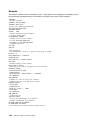
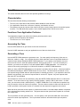
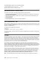
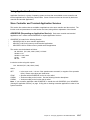
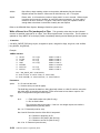
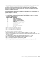
4690 Store System:
ÉÂÔ
Programming Guide
SC30-3602-02
Note
Before using this information and the product it supports, be sure to read the general information under “Notices”
on page vii.
|
Third Edition (July 1996)
This edition applies to Version 1 Release 2 of the licensed program IBM 4690 Operating System, program number 5696-538, and to
all subsequent releases and modifications until otherwise indicated in new editions. Changes are made periodically to the
information herein.
Order publications through your IBM representative or the IBM branch office serving your locality. Publications are not stocked at the
address given below.
A form for readers’ comments is provided at the back of this publication. If the form has been removed, address your comments to:
IBM Corporation
Information Development, Department CJMA
PO Box 12195
RESEARCH TRIANGLE PARK, NC 27709
USA
When you send information to IBM, you grant IBM a nonexclusive right to use or distribute whatever information you supply in any
way it believes appropriate without incurring any obligation to you.
Copyright International Business Machines Corporation 1994, 1996. All rights reserved.
Note to U.S. Government Users — Documentation related to restricted rights — Use, duplication or disclosure is subject to
restrictions set forth in GSA ADP Schedule Contract with IBM Corp.
Contents
|
Notices . . . . . . . . . . . . . . . . . . . . . . . .
Trademarks . . . . . . . . . . . . . . . . . . . . . .
Preface
. . . . . . . . . . . . . . . . . . . . . . . .
Who Should Read This Book . . . . . . . . . . . .
How to Use This Book . . . . . . . . . . . . . . . .
Terminal Models . . . . . . . . . . . . . . . . . . .
Where to Find More Information . . . . . . . . . .
Store System Related Publications — Software
Store System Related Publications — Hardware
General Publications . . . . . . . . . . . . . . .
Summary of Changes . . . . . . . . . . . . . . . .
. . . . . . . . . . . . . . . . . . . . . . . . . . . . . . .
. . . . . . . . . . . . . . . . . . . . . . . . . . . . . . .
. . . . . . . . . . . . . . . . . . . . . . . . . . . . . . .
. . . . . . . . . . . . . . . . . . . . . . . . . . . . . . .
. . . . . . . . . . . . . . . . . . . . . . . . . . . . . . .
. . . . . . . . . . . . . . . . . . . . . . . . . . . . . . .
. . . . . . . . . . . . . . . . . . . . . . . . . . . . . . .
. . . . . . . . . . . . . . . . . . . . . . . . . . . . . .
. . . . . . . . . . . . . . . . . . . . . . . . . . . . . .
. . . . . . . . . . . . . . . . . . . . . . . . . . . . . . .
. . . . . . . . . . . . . . . . . . . . . . . . . . . . . . .
vii
vii
viii
viii
viii
ix
ix
ix
x
xii
xiii
Part 1: The IBM 4690 Operating System Environment
Chapter 1. The IBM 4690 Operating System Environment
. . . . . . . . . . . . . . . . . . . . . . . .
System Capabilities
Concurrent Operations . . . . . . . . . . . . . . . . . . . . . . .
Operator Interface . . . . . . . . . . . . . . . . . . . . . . . . .
Changing the Signon Screen . . . . . . . . . . . . . . . . . . .
Communications . . . . . . . . . . . . . . . . . . . . . . . . . .
Files . . . . . . . . . . . . . . . . . . . . . . . . . . . . . . . . .
. . . . . . . . . . . . . . . . . . .
Problem Determination Aids
Utilities . . . . . . . . . . . . . . . . . . . . . . . . . . . . . . . .
Additional Products . . . . . . . . . . . . . . . . . . . . . . . . .
Store Controller Backup . . . . . . . . . . . . . . . . . . . . . .
. . . . . . . . . . . . . . . . . . . . . . .
. . . . . . . . . . . . . . . . . . . . . . .
. . . . . . . . . . . . . . . . . . . . . . .
. . . . . . . . . . . . . . . . . . . . . . .
. . . . . . . . . . . . . . . . . . . . . . .
. . . . . . . . . . . . . . . . . . . . . . .
. . . . . . . . . . . . . . . . . . . . . . .
. . . . . . . . . . . . . . . . . . . . . . .
. . . . . . . . . . . . . . . . . . . . . . .
. . . . . . . . . . . . . . . . . . . . . . .
. . . . . . . . . . . . . . . . . . . . . . .
Chapter 2. Managing Files . . . . . . . . . . . . . . . . . . . . . . . . .
Selecting File Types . . . . . . . . . . . . . . . . . . . . . . . . . . . . . .
Naming Files and Subdirectories . . . . . . . . . . . . . . . . . . . . . . .
Rules for Naming Subdirectories and Files . . . . . . . . . . . . . . . . .
Using Logical Names
. . . . . . . . . . . . . . . . . . . . . . . . . . . . .
Logical File Names on a LAN (MCF Network) System . . . . . . . . . .
Accessing Distributed Files in Store Controller and Terminal Applications
Using File Names in Store Controller Applications . . . . . . . . . . . . .
Using File Names in Terminal Applications . . . . . . . . . . . . . . . . .
Using Node Names to Access Files . . . . . . . . . . . . . . . . . . . . .
Performing File Functions . . . . . . . . . . . . . . . . . . . . . . . . . . .
Design Considerations for File Performance . . . . . . . . . . . . . . . .
|
|
|
|
Chapter 3. Programming Terminal I/O Devices
2x20 Displays . . . . . . . . . . . . . . . . . . . . .
Shopper Display . . . . . . . . . . . . . . . . . . .
Video Display . . . . . . . . . . . . . . . . . . . . .
Cash Drawer Driver . . . . . . . . . . . . . . . . .
Coin Dispenser Driver . . . . . . . . . . . . . . . .
I/O Processor . . . . . . . . . . . . . . . . . . . . .
Magnetic Stripe Reader Driver . . . . . . . . . . .
Printer Driver Model 2 . . . . . . . . . . . . . . . .
Printer Driver Model 3 or 4 . . . . . . . . . . . . .
Copyright IBM Corp. 1994, 1996
. . . . . . . . . . . . . . . . .
. . . . . . . . . . . . . . . . .
. . . . . . . . . . . . . . . . .
. . . . . . . . . . . . . . . . .
. . . . . . . . . . . . . . . .
. . . . . . . . . . . . . . . .
. . . . . . . . . . . . . . .
. . . . . . . . . . . . . . . .
. . . . . . . . . . . . . . . .
. . . . . . . . . . . . . . . .
. . . . . . . . . . . . . . . .
. . . . . . . . . . . . . . . .
. . . . . . . . . . . . . . . . . . . . . . . . . . . . .
. . . . . . . . . . . . . . . . . . . . . . . . . . . . . .
. . . . . . . . . . . . . . . . . . . . . . . . . . . . .
. . . . . . . . . . . . . . . . . . . . . . . . . . . . .
. . . . . . . . . . . . . . . . . . . . . . . . . . . . .
. . . . . . . . . . . . . . . . . . . . . . . . . . . . .
. . . . . . . . . . . . . . . . . . . . . . . . . . . . .
. . . . . . . . . . . . . . . . . . . . . . . . . . . . .
. . . . . . . . . . . . . . . . . . . . . . . . . . . . .
. . . . . . . . . . . . . . . . . . . . . . . . . . . . .
1-1
1-1
1-1
1-2
1-2
1-2
1-3
1-3
1-3
1-4
1-4
2-1
2-2
2-7
2-8
2-11
2-13
2-14
2-17
2-17
2-18
2-18
2-28
3-1
3-6
3-10
3-12
3-27
3-29
3-31
3-48
3-60
3-67
iii
|
Magnetic Ink Character Recognition Support for Printers Model 3 and 4
Fiscal Printer Support . . . . . . . . . . . . . . . . . . . . . . . . . . . . .
Scale Driver . . . . . . . . . . . . . . . . . . . . . . . . . . . . . . . . . . .
Serial I/O Communications Driver . . . . . . . . . . . . . . . . . . . . . .
Tone Driver . . . . . . . . . . . . . . . . . . . . . . . . . . . . . . . . . . .
Totals Retention Driver
. . . . . . . . . . . . . . . . . . . . . . . . . . . .
Chapter 4. Using Error Recovery Procedures and Facilities
Error Recovery Options . . . . . . . . . . . . . . . . . . . . . . .
Error Functions and Statements . . . . . . . . . . . . . . . . . .
. . . . . . . . . . . . . . . . . . . . . . .
Logging System Errors
Audible Alarm . . . . . . . . . . . . . . . . . . . . . . . . . . . . .
Distribution Exception Log . . . . . . . . . . . . . . . . . . . . . .
Power Line Disturbance Recovery . . . . . . . . . . . . . . . . .
Storage Retention . . . . . . . . . . . . . . . . . . . . . . . . . .
Terminal Power ON/OFF . . . . . . . . . . . . . . . . . . . . . .
Disk and File Error Recovery . . . . . . . . . . . . . . . . . . . .
Error Recovery for I/O Devices . . . . . . . . . . . . . . . . . . .
. . . . . . . . . . . . . . . .
. . . . . . . . . . . . . . . .
. . . . . . . . . . . . . . . .
. . . . . . . . . . . . . . . .
. . . . . . . . . . . . . . . .
. . . . . . . . . . . . . . . .
. . . . . . . . . . . . . . . . . . . . .
. . . . . . . . . . . . . . . . . . . . . .
. . . . . . . . . . . . . . . . . . . . . .
. . . . . . . . . . . . . . . . . . . . . .
. . . . . . . . . . . . . . . . . . . . . .
. . . . . . . . . . . . . . . . . . . . . .
. . . . . . . . . . . . . . . . . . . . . .
. . . . . . . . . . . . . . . . . . . . .
. . . . . . . . . . . . . . . . . . . . .
. . . . . . . . . . . . . . . . . . . . .
. . . . . . . . . . . . . . . . . . . . .
Chapter 5. User Application Considerations with a LAN (MCF Network)
Using TCLOSE to Close Application Data Files . . . . . . . . . . . . . . . . .
Application Read Restrictions . . . . . . . . . . . . . . . . . . . . . . . . . . . .
Spool Files on a LAN (MCF Network) System . . . . . . . . . . . . . . . . . .
. . . . . . . . .
Effects of Activating the Alternate File Server on Despooling
Record Sizes . . . . . . . . . . . . . . . . . . . . . . . . . . . . . . . . . . . . .
Using the Application Program Interface (OS/2) . . . . . . . . . . . . . . . . .
Using the Application Program Interface (DOS) . . . . . . . . . . . . . . . . .
. . . . . . . . . . . . . .
. . . . . . . . . . . . . .
. . . . . . . . . . . . . .
. . . . . . . . . . . . . .
. . . . . . . . . . . . . .
. . . . . . . . . . . . . .
. . . . . . . . . . . . . .
. . . . . . . . . . . . . .
3-79
3-82
3-87
3-89
3-96
3-98
4-1
4-1
4-2
4-4
4-6
4-9
4-9
4-10
4-10
4-10
4-13
5-1
5-1
5-1
5-2
5-3
5-4
5-4
5-6
Part 2: Utilities
Chapter 6. Using the Keyed File Utility
Accessing the Keyed File Utility . . . . .
Using the Keyed File Utility from the Host
Using the Keyed File Utility in a Batch File
Keyed File Utility Working Files . . . . . .
Hashing Algorithms . . . . . . . . . . . . .
Internal Processes of Keyed Files . . . .
|
. . . . . . . . . . . . . . . . . . . . . . . . . . . . . . . . . .
. . . . . . . . . . . . . . . . . . . . . . . . . . . . . . . . . . .
. . . . . . . . . . . . . . . . . . . . . . . . . . . . . . . . . .
. . . . . . . . . . . . . . . . . . . . . . . . . . . . . . . . . .
. . . . . . . . . . . . . . . . . . . . . . . . . . . . . . . . . .
. . . . . . . . . . . . . . . . . . . . . . . . . . . . . . . . . .
. . . . . . . . . . . . . . . . . . . . . . . . . . . . . . . . . .
Chapter 7. Using the Input Sequence Table Build Utility
Input Sequence Tables . . . . . . . . . . . . . . . . . . . . . .
Using the Input State Table Utility . . . . . . . . . . . . . . . .
Running the Input Sequence Table Utility . . . . . . . . . . . .
Input Sequence Table Utility on a LAN (MCF Network) System
Chapter 8. Using the LIB86 Library Utility
Using LIB86 Command-Line Options . . . .
Creating a Library File . . . . . . . . . . . . .
Appending an Existing Library . . . . . . . .
Replacing Library Modules . . . . . . . . . .
Deleting Library Modules . . . . . . . . . . .
Selecting Modules . . . . . . . . . . . . . . .
Displaying Library Information
. . . . . . . .
Accessing Files in Other Directories . . . . .
iv
4690 Store System: Programming Guide
. . . . . . . . . . . . . . . . . . . . . . .
. . . . . . . . . . . . . . . . . . . . . . .
. . . . . . . . . . . . . . . . . . . . . . .
. . . . . . . . . . . . . . . . . . . . . . .
. . . . . . . . . . . . . . . . . . . . . .
. . . . . . . . . . . . . . . . . . . . . . . . . . . . . . . .
. . . . . . . . . . . . . . . . . . . . . . . . . . . . . . . . .
. . . . . . . . . . . . . . . . . . . . . . . . . . . . . . . . .
. . . . . . . . . . . . . . . . . . . . . . . . . . . . . . . . .
. . . . . . . . . . . . . . . . . . . . . . . . . . . . . . . . .
. . . . . . . . . . . . . . . . . . . . . . . . . . . . . . . . .
. . . . . . . . . . . . . . . . . . . . . . . . . . . . . . . . .
. . . . . . . . . . . . . . . . . . . . . . . . . . . . . . . . .
. . . . . . . . . . . . . . . . . . . . . . . . . . . . . . . . .
6-1
6-2
6-2
6-4
6-10
6-10
6-12
7-1
7-1
7-1
7-2
7-2
8-1
8-2
8-3
8-3
8-4
8-4
8-5
8-5
8-6
Chapter 9. Using the Linker Utility and the POSTLINK Utility
Introduction to the Linker Utility . . . . . . . . . . . . . . . . . . . .
LINK86 Command Syntax . . . . . . . . . . . . . . . . . . . . . . .
Linking With Shared Runtime Libraries . . . . . . . . . . . . . . .
LINK86 Command Options . . . . . . . . . . . . . . . . . . . . . .
Use of Link Path Variables to Search Other Directories
. . . . .
How Various Search Priorities Relate . . . . . . . . . . . . . . . .
Use of ERRORLEVEL Test . . . . . . . . . . . . . . . . . . . . . .
Overlays . . . . . . . . . . . . . . . . . . . . . . . . . . . . . . . . .
The POSTLINK Utility . . . . . . . . . . . . . . . . . . . . . . . . .
Chapter 10. Using the Print Spooler Utility
Obtaining Job Status after a TCLOSE . . . .
Issuing a Command to the Print Spooler . .
Using Special Commands . . . . . . . . . . .
Error Return Codes for the Print Spooler . .
|
|
|
|
|
|
. . . . . . . . . . . . . . . . . . . . .
. . . . . . . . . . . . . . . . . . . . .
. . . . . . . . . . . . . . . . . . . . .
. . . . . . . . . . . . . . . . . . . .
. . . . . . . . . . . . . . . . . . . .
. . . . . . . . . . . . . . . . . . . .
. . . . . . . . . . . . . . . . . . . .
. . . . . . . . . . . . . . . . . . . .
. . . . . . . . . . . . . . . . . . . . . . . . . . . . . . .
. . . . . . . . . . . . . . . . . . . . . . . . . . . . . . . .
. . . . . . . . . . . . . . . . . . . . . . . . . . . . . . . .
. . . . . . . . . . . . . . . . . . . . . . . . . . . . . . . .
. . . . . . . . . . . . . . . . . . . . . . . . .
. . . . . . . . . . . . . . . . . . . . . . . . . .
. . . . . . . . . . . . . . . . . . . . . . . . . .
. . . . . . . . . . . . . . . . . . . . . . . . . .
. . . . . . . . . . . . . . . . . . . . . . . . . .
. . . . . . . . . . . . . . . . . . . . . . . . . .
. . . . . . . . . . . . . . . . . . . . . . . . .
. . . . . . . . . . . . . . . . . . . . . . . . . .
. . . . . . . . . . . . . . . . . . . . . . . . . .
Chapter 12. Using the Loop Status Application Utility
|
. . . . . . . . . . . . . . . . . . . . .
. . . . . . . . . . . . . . . . . . . . . . . . . . . . . . . .
Chapter 11. Using the Disk Surface Analysis Utility
Introduction to the Disk Surface Analysis Utility . . . .
IPL Command Processor . . . . . . . . . . . . . . . . .
. . . . . . . . . . . . . . .
Disk Surface Analysis Utility
Parameter Descriptions for ADXCSW0L
. . . . . . . .
Command Formats for ADXCSW0L . . . . . . . . . . .
Using the Disk Surface Analysis Utility to Recover Data
Using the Time Frame Indicators . . . . . . . . . . . . .
Case Examples of Disk Recovery . . . . . . . . . . . .
Chapter 13. Using the Staged IPL Utility
Requirements . . . . . . . . . . . . . . . . .
Capabilities . . . . . . . . . . . . . . . . . .
Application Interface . . . . . . . . . . . . .
Loading Terminal Storage . . . . . . . . . .
Messages . . . . . . . . . . . . . . . . . . .
ASM History File . . . . . . . . . . . . . . .
. . . . . . . . . . . . . . . . . . . . .
9-1
9-2
9-3
9-4
9-4
9-11
9-12
9-12
9-12
9-15
10-1
10-1
10-2
10-3
10-5
11-1
11-1
11-1
11-3
11-4
11-4
11-7
11-8
11-8
. . . . . . . . . . . . . . . . . . . . . . . .
12-1
. . . . . . . . . . . . . . . . . . . . . . . . . . . . . . . .
13-1
13-1
13-2
13-3
13-7
13-8
13-10
. . . . . . . . . . . . . . . . . . . . . . . . . . . . . . . . .
. . . . . . . . . . . . . . . . . . . . . . . . . . . . . . . . .
. . . . . . . . . . . . . . . . . . . . . . . . . . . . . . . . .
. . . . . . . . . . . . . . . . . . . . . . . . . . . . . . . . .
. . . . . . . . . . . . . . . . . . . . . . . . . . . . . . . . .
. . . . . . . . . . . . . . . . . . . . . . . . . . . . . . . . .
Chapter 14. Using the Multiple File Archiver Utility
Compressing, Combining, and Archiving Files . . . . .
Mapping the Combine File
. . . . . . . . . . . . . . . .
Splitting Files Out of a Combine File . . . . . . . . . . .
Splitting a Given List of Files from a Combine File
. .
Log Files . . . . . . . . . . . . . . . . . . . . . . . . . . .
Return Codes . . . . . . . . . . . . . . . . . . . . . . . .
. . . . . . . . . . . . . . . . . . . . . . . . . .
. . . . . . . . . . . . . . . . . . . . . . . . . .
. . . . . . . . . . . . . . . . . . . . . . . . . .
. . . . . . . . . . . . . . . . . . . . . . . . . .
. . . . . . . . . . . . . . . . . . . . . . . . . .
. . . . . . . . . . . . . . . . . . . . . . . . . .
. . . . . . . . . . . . . . . . . . . . . . . . . .
14-1
14-2
14-3
14-4
14-4
14-5
14-5
Part 3: Applications (Designing and Using)
Chapter 15. Designing Applications with IBM 4680 BASIC
Types of Applications . . . . . . . . . . . . . . . . . . . . . . .
Application Size . . . . . . . . . . . . . . . . . . . . . . . . . . .
Application Priorities . . . . . . . . . . . . . . . . . . . . . . . .
Starting a Background Application . . . . . . . . . . . . . . . .
. . . . . . . . . . . . . . . . . . . . . . .
System Authorization
. . . . . . . . . . . . . . . . . . . . .
. . . . . . . . . . . . . . . . . . . . . .
. . . . . . . . . . . . . . . . . . . . . .
. . . . . . . . . . . . . . . . . . . . . .
. . . . . . . . . . . . . . . . . . . . . .
. . . . . . . . . . . . . . . . . . . . . .
15-1
15-2
15-3
15-5
15-6
15-8
Contents
v
Communicating between Applications
Using Application Services . . . . .
Chaining Applications . . . . . . . .
RAM Disk Files . . . . . . . . . . . .
. . . . . . . . . . . . . . . . . . . . . . . . . . . . . . . . . . . .
. . . . . . . . . . . . . . . . . . . . . . . . . . . . . . . . . . . . .
. . . . . . . . . . . . . . . . . . . . . . . . . . . . . . . . . . . . .
. . . . . . . . . . . . . . . . . . . . . . . . . . . . . . . . . . . . .
Chapter 16. Designing Applications with Other Languages .
4690 Operating System Interfaces for C and COBOL . . . . . . .
Guidelines and Restrictions for Assembly Language Applications
Chapter 17. Using IBM DOS Applications . . .
Starting Applications in the IBM DOS Environment
IBM DOS Program Memory Allocation
. . . . . .
Allocating Memory Using ADDMEM . . . . . . . .
Optional Emulator Reports . . . . . . . . . . . . .
Selecting Reports Using EOPTIONS
. . . . . . .
IBM DOS BIOS Calls and Software Interrupts . .
DOS Function Calls . . . . . . . . . . . . . . . . .
Emulator Messages . . . . . . . . . . . . . . . . .
. . . . . . . . . . . . . . . . . . . .
. . . . . . . . . . . . . . . . . . . .
. . . . . . . . . . . . . . . . . . . .
. . . . . . . . . . . . . . . . . . . . . . . . . . . . .
. . . . . . . . . . . . . . . . . . . . . . . . . . . .
. . . . . . . . . . . . . . . . . . . . . . . . . . . . .
. . . . . . . . . . . . . . . . . . . . . . . . . . . . .
. . . . . . . . . . . . . . . . . . . . . . . . . . . . .
. . . . . . . . . . . . . . . . . . . . . . . . . . . . .
. . . . . . . . . . . . . . . . . . . . . . . . . . . . .
. . . . . . . . . . . . . . . . . . . . . . . . . . . . .
. . . . . . . . . . . . . . . . . . . . . . . . . . . . .
15-11
15-17
15-30
15-31
16-1
16-2
16-48
17-1
17-1
17-2
17-3
17-3
17-3
17-4
17-6
17-6
Appendixes
Appendix A. IBM 4690 Operating System Disk Directory
Protecting the IBM 4690-Provided Subdirectories . . . . . .
Naming Conventions for 4690 Operating System Files . . .
Dictionary of 4690 Operating System Files . . . . . . . . . .
Appendix B. Error Messages
LIB86 Error Messages . . . . .
POSTLINK Error Messages . .
LINK86 Error Messages . . . .
. . . . . . . . . . . . . . . . . . . . . . .
. . . . . . . . . . . . . . . . . . . . . . . .
. . . . . . . . . . . . . . . . . . . . . . . .
. . . . . . . . . . . . . . . . . . . . . . . .
. . . . . . . . . . . . . . . . . . . . . . . . . . . . . . . . . . . . . . . .
. . . . . . . . . . . . . . . . . . . . . . . . . . . . . . . . . . . . . . . . .
. . . . . . . . . . . . . . . . . . . . . . . . . . . . . . . . . . . . . . . . .
. . . . . . . . . . . . . . . . . . . . . . . . . . . . . . . . . . . . . . . . .
Appendix C. Character Sets and Check Printing Application
Example of a Normal Width Character Set . . . . . . . . . . . . .
Example of a Double Width Character Set . . . . . . . . . . . . .
Example Application for Printing Checks on the Model 2 Printer
Glossary
Index
vi
A-1
A-1
A-2
A-3
B-1
B-1
B-4
B-8
. . . . . . . . . . . . . . . . . . . . .
C-1
C-1
C-2
C-3
. . . . . . . . . . . . . . . . . . . . . . . . . . . . . . . . . . . . . . . . . . . . . . . . . . . . .
X-1
. . . . . . . . . . . . . . . . . . . . .
. . . . . . . . . . . . . . . . . . . . .
. . . . . . . . . . . . . . . . . . . . .
. . . . . . . . . . . . . . . . . . . . . . . . . . . . . . . . . . . . . . . . . . . . . . . . . . . . . . .
4690 Store System: Programming Guide
X-23
Notices
References in this publication to IBM products, programs, or services do not imply that IBM intends to
make these available in all countries in which IBM operates. Any reference to an IBM product, program,
or service in this publication is not intended to state or imply that only IBM’s product, program, or service
may be used. Any functionally equivalent product, program, or service that does not infringe any of IBM’s
intellectual property rights may be used instead of the IBM product, program, or service. Evaluation and
verification of operation in conjunction with other products, programs, or services, except those expressly
designated by IBM, are the user’s responsibility.
IBM may have patents or pending patent applications covering subject matter in this document. The
furnishing of this document does not give you any license to these patents. You can send license
inquiries, in writing, to the IBM Director of Licensing, IBM Corporation, 500 Columbus Avenue
THORNWOOD, NY 10594 USA.
Trademarks
The following terms are trademarks of the IBM Corporation in the United States or other countries or both:
AS/400
Display Manager
NetView
Personal System/2
System/370
XT
C/2
IBM
Operating System/2
PS/2
Systems Application Architecture
COBOL/2
Micro Channel
OS/2
SAA
AIX
Other company, product, and service names, which may be denoted by a double asterisk (**), may be
trademarks or service marks of others.
Copyright IBM Corp. 1994, 1996
vii
Preface
This book describes how to program the IBM 4690 Operating System and the interfaces for application
programs.
Who Should Read This Book
This book is written for the programmer who uses system services or writes application programs to run
on the 4690 Operating System.
How to Use This Book
The book is organized into the following parts:
¹ Part 1—The IBM 4690 Operating System Environment
– Chapter 1 contains an overview of the 4690 Operating System environment and describes the
system capabilities, terminal models, and problem determination aids.
– Chapter 2 describes how you can manage your files. It provides information on naming files and
subdirectories, and performing file functions.
– Chapter 3 contains information on programming terminal input/output (I/O) devices.
– Chapter 4 provides information on error recovery procedures and facilities. This information
includes error recovery options, logging system errors, and storage retention.
– Chapter 5 describes options you should consider when using an application with a local area
network (LAN).
¹ Part 2—Utilities
– Chapter 6 describes the Keyed File Utility (KFU) and provides instructions for using the utility.
– Chapter 7 describes the input sequence tables and provides example worksheets for you to use
when designing the input sequence tables.
– Chapter 8 describes the Library Utility (LIB86). The chapter contains information on using
command-line options, creating a library file, and displaying library information.
– Chapter 9 describes the Linker and Postlink utilities. This information includes using link path
variables, input file options, and command syntax.
– Chapter 10 describes the Print Spooler Utility, which allows you to send files to one of eight
queues for printing on one of eight printers.
– Chapter 11 provides information on the Disk Surface Analysis Utility, including parameter
descriptions and time-frame indicators.
– Chapter 12 describes the Loop Status Application Utility, including formats to use to invoke the
utility.
– Chapter 13 describes the Staged IPL Utility. The chapter contains the requirements, capabilities,
and application interface for using the utility.
¹ Part 3—Applications (Designing and Using)
– Chapter 15 contains information for designing applications with IBM 4680 BASIC.
– Chapter 16 contains information for designing applications with other programming languages.
viii
4690 Store System: Programming Guide
¹ Appendixes
– Appendix A describes the 4690 Operating System hierarchical directory structure. This appendix
includes information on naming conventions for 4690 Operating System files.
– Appendix B provides error messages for the Library, Postlink, and Linker utilities.
– Appendix C describes character sets and the check printing application.
– The glossary defines new, unique, and unfamiliar terms and abbreviations used in this book.
– The index provides a quick reference to the contents of the book.
Terminal Models
|
|
|
|
|
|
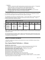
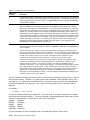
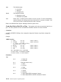
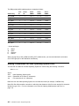
The 4683/4693-xx1/4694 terminals are called Mod1 terminals. Although all are called Mod1 terminals,
each terminal model supports some features that other models do not support.
The 4683/4693-xx2 terminals are called Mod2 terminals. These terminals attach to a Mod1 terminal and
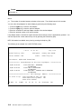
depend upon that Mod1 terminal for control and communication with the store controller. Table 0-1
shows the different Mod1 and Mod2 terminals.
Table 0-1. Mod1 and Mod2 Terminals by Machine Type
4683 Terminals
4693 Terminals
4694 Terminals
|
Mod1
Mod2
Mod1
Mod2
Mod1
Mod2
|
|
|
|
|
|
4683-P11
4683-P21
4683-P41
4683-001
4683-A01
4683-421
4683-xx2
4683-xx2
4683-xx2
4683-xx2
4683-xx2
4683-xx2
4693-7x1
4693-5x1
4693-4x1
4693-3x1
4693-xx2
4693-xx2
4693-xx2
Not supported
4694-144
Not supported
Note: A 4683-xx2 terminal cannot attach to a 4693 Mod1 terminal. A 4693-xx2 terminal cannot attach to
a 4683 Mod1 terminal.
The controller/terminal (for example, a 4684 or 4693-5x1 controller/terminal) combines the function of the
store controller and point-of-sale terminal in a single product. The terminal portion of a controller/terminal
is considered to be a Mod1 terminal.
Where to Find More Information
A CD-ROM is available that contains the online books that are a part of the IBM Store Systems Library
Collection, SK2T-0331.
Store System Related Publications — Software
IBM 4690 Store System Library
IBM 4690 Store System: Touch Screen Support for 4690 OS Programming Guide, SGC30-3780
IBM 4690 Store System: Planning, Installation, and Configuration Guide, GC30-3600
IBM 4690 Store System: User’s Guide, SC30-3597
IBM 4690 Store System: Communications Programming Reference, SC30-3582
IBM 4690 Store System: Messages Guide, SC30-3598
IBM 4680 Store System: Preparing Your Site, GA27-3692
IBM 4680 BASIC: Language Reference, SC30-3356
IBM 4680 Store System: Display Manager User’s Guide, SC30-3404
IBM 4690 Store System: 4690 Terminal Services for DOS User’s Guide, SC30-3688
The CAPITPGP.DOC file included with AISPO product number, 5764-091 Version 1.1 or later, the IBM C
Programming Interface for the 4690 Terminals.
Notices
ix
IBM 4680 and 4680-90 General Sales Application
IBM 4680-90 General Sales Application: Planning and Installation Guide, GC30-3630
IBM 4680-90 General Sales Application: Guide to Operations, SC30-3632
IBM 4680-90 General Sales Application: Programming Guide, SC30-3631
IBM 4680 General Sales Application – Price Management Feature: User’s Guide, SC30-3461
IBM 4680 General Sales Application – Terminal Offline Feature: User’s Guide, SC30-3499
IBM 4680-90 General Sales Application: Full Screen – Guide to Operations, SC30-3664
IBM 4680-90 General Sales Application: Master Index, GX27-3958
IBM 4680 and 4680-90 Supermarket Application
IBM 4680-90 Supermarket Application: Planning and Installation Guide, GC30-3633
IBM 4680-90 Supermarket Application: Guide to Operations, SC30-3635
IBM 4680-90 Supermarket Application: Programming Guide, SC30-3634
IBM 4680 Supermarket Application – Terminal Offline Feature: User’s Guide, SC30-3512
IBM 4680 Supermarket Application – Electronic Funds Transfer Feature: User’s Guide, SC30-3513
IBM 4680-4690 Supermarket Application – Electronic Funds Transfer Feature Enhancement: User’s Guide,
SC30-3718
IBM 4680-90 Supermarket Application: Master Index, GX27-3957
IBM 4680 Chain Drug Sales Application
IBM 4680 Chain Drug Sales Application: Planning and Installation Guide, GC30-3412
IBM 4680 Chain Drug Sales Application: Guide to Operations, SC30-3413
IBM 4680 Chain Drug Sales Application: Programming Guide, SC30-3414
IBM 4680 Store Management Application
IBM 4680 Store Management Application: Planning and Installation Guide, GC30-3483
IBM 4680 Store Management Application: Guide to Operations, SC30-3484
IBM 4680 Store Management Application: Programming Guide, SC30-3487
IBM 4680 Store Management Application – Inventory Control Feature: User’s Guide, SC30-3485
IBM 4680 Store Management Application – Price Management Feature: User’s Guide, SC30-3486
IBM Systems Application Architecture
IBM Systems Application Architecture: Common Programming Interface Communications Reference,
SC26-4399
In-Store Processing
In-Store Processing: Application Development Guide, SC30-3534
In-Store Processing: IBM AIX – Application Development Guide, SC30-3537
In-Store Processing: IBM OS/2 Extended Edition – Application Development Guide, SC30-3538
In-Store Processing: IBM OS/400 – Application Development Guide, SC30-3535
In-Store Processing: IBM 4680 OS – Application Development Guide, SC30-3536
Store System Related Publications — Hardware
|
|
|
|
|
|
IBM 4694 Point-of-Sale Terminals
IBM 4694 Point-of-Sale Terminals: Installation and Operation Guide, SA27-4005
IBM Store Systems: Installation and Operation for Point-of-Sale Input/Output Devices, GA27-4028
IBM 4693, 4694, and 4695 Point-of-Sale Terminals: Hardware Service Manual, SY27-0337
IBM Store Systems: Hardware Service Manual for Point-of-Sale Input/Output Devices, SY27-0339
IBM Store Systems: Parts Catalog, S131-0097
IBM 4693 Point-of-Sale Terminals
IBM 4693 Point-of-Sale Terminals: Installation and Operation Guide, SA27-3978
IBM Store Systems: Installation and Operation for Point-of-Sale Input/Output Devices, GA27-4028
x
4690 Store System: Programming Guide
IBM
IBM
IBM
IBM
IBM
IBM
IBM
IBM
IBM
4693 Point-of-Sale Terminals: Setup Instructions, P/N 73G1012
4693 Point-of-Sale Terminals: Quick Reference Card, P/N 73G1022
4693, 4694, and 4695 Point-of-Sale Terminals: Maintenance and Test Summary, SX27-3919
4693, 4694, and 4695 Point-of-Sale Terminals: Hardware Service Manual, SY27-0337
Store Systems: Hardware Service Manual for Point-of-Sale Input/Output Devices, SY27-0339
Store Systems: Parts Catalog, S131-0097
4693 Point-of-Sale Terminals: Reference Diskette, SX27-3918
4693 Point-of-Sale Terminals: Diagnostic Diskette, SX27-3928
4693 Point-of-Sale Terminals: Support Diskette for Medialess Terminals, SX27-3929
IBM 4683/4684 Point-of-Sale Terminals
IBM 4683 Point-of-Sale Terminal: Installation Guide, SA27-3783
IBM 4684 Point-of-Sale Terminal: Installation Guide, SA27-3837
IBM 4684 Point-of-Sale Terminal: Introduction and Planning Guide, SA27-3835
IBM 4684 Store Loop Adapter/A: Installation, Testing, Problem Determination,
and Technical Reference, SD21-0045
IBM 4683/4684 Point-of-Sale Terminal: Operations Guide, SA27-3704
IBM 4680 Store System and IBM 4683/4684 Point-of-Sale Terminal:
Problem Determination Guide, SY27-0330
IBM 4684 Point-of-Sale Terminal: Maintenance Summary Card, SX27-3885
IBM 4680 Store System: Terminal Test Procedures Reference Summary, GX27-3779
IBM 4683/4684 Point-of-Sale Terminal: Maintenance Manual, SY27-0295
IBM Store Systems: Hardware Service Manual for Point-of-Sale Input/Output Devices , SY27-0339
IBM Store Systems: Hardware Technical Reference, SY27-0336
IBM Store Systems: Parts Catalog, S131-0097
Scanners
IBM 1520 Hand-Held Scanner User’s Guide, GA27-3685
IBM 4686 Retail Point-of-Sale Scanner: Physical Planning, Installation, and Operation Guide, SA27-3854
IBM 4686 Retail Point-of-Sale Scanner: Maintenance Manual, SY27-0319
IBM 4687 Point-of-Sale Scanner Model 1: Physical Planning, Installation, and Operation Guide,
SA27-3855
IBM 4687 Point-of-Sale Scanner Model 1: Maintenance Manual, SY27-0317
IBM 4687 Point-of-Sale Scanner Model 2: Physical Planning Guide, SA27-3882
IBM 4687 Point-of-Sale Scanner Model 2: Operator’s Guide, SA27-3884
IBM 4687 Point-of-Sale Scanner Model 2: Maintenance Manual, SY27-0324
IBM 4696 Point-of-Sale Scanner Scale: Physical Planning, Installation, and Operation Guide, GA27-3965
IBM 4696 Point-of-Sale Scanner Scale: Maintenance Manual, SY27-0333
IBM 4696 Point-of-Sale Scanner Scale: Specification Sheet, G221-3361
IBM 4697 Point-of-Sale Scanner Model 001: Maintenance Manual, SY27-0338
IBM 4697 Point-of-Sale Scanner Model 001: Physical Planning, Installation, and Operations Guide,
SY27-3990
IBM Personal Computer
IBM Personal System/2 –
IBM Personal System/2 –
IBM Personal System/2 –
IBM Personal System/2 –
IBM Personal System/2 –
SK2T-0319
and IBM Personal System/2
Model 50 Quick Reference and Reference Diskette, S68X-2247
Model 60 Quick Reference and Reference Diskette, S68X-2213
Model 70 Quick Reference and Reference Diskette, S68X-2308
Model 80 Quick Reference and Reference Diskette, S68X-2284
Store Loop Adapter/A – Supplements for the Hardware Maintenance Library,
Notices
xi
Cabling
A Building Planning Guide for Communication Wiring, G320-8059
IBM Cabling System Planning and Installation Guide, GA27-3361
IBM Cabling System Catalog, G570-2040
Using the IBM Cabling System with Communication Products, GA27-3620
Networks
IBM Local Area Network Support Program, IBM P/N 83X7873
IBM Token-Ring Network Introduction and Planning Guide, GA27-3677
IBM Personal System/2 Store Loop Adapter/A: Installation and Setup Instructions, SK2T-0318
General Publications
Advanced Data Communications for Stores – General Information, GH20-2188
Distributed Systems Executive – General Information, GH19-6394
Communications Manager X.25 Programming Guide, SC31-6167
IBM Disk Operating System 4.0 Command Reference, S628-0253
IBM Proprinters, SC31-3793
IBM 4680 Support for COBOL Version 2 (Softcopy provided with the product)
IBM 4680 Store System Regression Tester (Softcopy provided with the product)
IBM 4680 X.25 Application Programming Interface, GG24-3952
NetView Distribution Manager: General Information, GH19-6587
Systems Network Architecture: General Overview, GC30-3073
IBM Local Area Network Administrator’s Guide, GA27-6367
DSX Preparing and Tracking Transmission Plans, SH19-6399
IBM Dictionary of Computing (New York; McGraw-Hill, Inc., 1993)
IBM Local Area Network Support Program, IBM P/N 83X7873
The Ethernet Management Guide – Keeping the Link, Second Edition (McGraw-Hill, Inc.,
ISBN 0-07-046320-4)
xii
4690 Store System: Programming Guide
|
Summary of Changes
|
The following information has been added or modified in this edition of the manual:
|
¹ 4694
|
¹ Touch Screen Support
|
¹ Programming I/O Devices
|
¹ Full-Screen Enhanced I/O Processor
|
¹ Fiscal Printers
|
¹ Multiple File Archiver Utility
Notices
xiii
xiv
4690 Store System: Programming Guide
Part 1: The IBM 4690 Operating System Environment
Copyright IBM Corp. 1994, 1996
4690 Store System: Programming Guide
Chapter 1. The IBM 4690 Operating System Environment
System Capabilities
. . . .
Concurrent Operations . . .
Operator Interface . . . . .
Changing the Signon Screen
Communications . . . . . .
Files . . . . . . . . . . . . .
Problem Determination Aids
Utilities . . . . . . . . . . . .
Additional Products . . . . .
Store Controller Backup . .
. . . . . . . . . . . . . . . . . . . . . . . . . . . . . . . . . . . . . . . . . . .
. . . . . . . . . . . . . . . . . . . . . . . . . . . . . . . . . . . . . . . . . . .
. . . . . . . . . . . . . . . . . . . . . . . . . . . . . . . . . . . . . . . . . . .
. . . . . . . . . . . . . . . . . . . . . . . . . . . . . . . . . . . . . . . . . .
. . . . . . . . . . . . . . . . . . . . . . . . . . . . . . . . . . . . . . . . . . .
. . . . . . . . . . . . . . . . . . . . . . . . . . . . . . . . . . . . . . . . . . .
. . . . . . . . . . . . . . . . . . . . . . . . . . . . . . . . . . . . . . . . . .
. . . . . . . . . . . . . . . . . . . . . . . . . . . . . . . . . . . . . . . . . . .
. . . . . . . . . . . . . . . . . . . . . . . . . . . . . . . . . . . . . . . . . . .
. . . . . . . . . . . . . . . . . . . . . . . . . . . . . . . . . . . . . . . . . . .
1-1
1-1
1-2
1-2
1-2
1-3
1-3
1-3
1-4
1-4
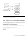
This chapter is an overview of the IBM 4690 Operating System environment. It provides the capabilities of
the system and refers you to other chapters for more detailed information.
System Capabilities
The IBM 4690 Operating System is a multitasking and multiuser environment that runs in the store
controller, the point-of-sale terminals, and the controller/terminals. The operating system can handle store
controller communications with point-of-sale terminals, other controllers, the controller/terminal, and the
host processor. The following sections briefly describe the system’s capabilities.
Concurrent Operations
The following functions of the 4690 Operating System allow concurrent operations:
¹ The operating system allows you to run your batch and interactive programs at the same time. One
program does not have to finish before another program can start.
¹ The operating system allows several operators to use the system at the same time. Your operators
can be authorized to run one program at a time or several at a time. Operators are authorized
through the system authorization file. See Chapter 15 for information on how to authorize users on
the system.
¹ Multiple users on the system can run multiple interactive applications through the use of windows. An
operator can switch from window to window, start or stop an application running on a window, or
check the status of an application running on a window. Windows are possible through a window
control facility. Refer to the IBM 4690 Store System: User’s Guide for an explanation on how windows
are used on the system.
¹ You can communicate with a host site at the same time your in-store communications are taking
place.
¹ You can attach multiple serial devices to your store controller. The Multiple Console facility handles
the management of these devices as additional system consoles.
Copyright IBM Corp. 1994, 1996
1-1
Operator Interface
For some system functions (for example, configuration) you communicate with the system through a
menu-driven interface at the store controller console. For other functions (for example, copying files) you
enter commands directly into the system. You can attach auxiliary consoles to the store controller. For
information on how to use system functions and auxiliary consoles, refer to the IBM 4690 Store System:
User’s Guide.
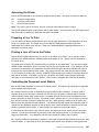
Changing the Signon Screen
You can change the signon screen displayed during signon by creating an alternate logo in the file
C:\ADX_IPGM\ADXLOGOD.DAT. If this file exists during system startup, the first 10 rows of data on the
signon screen are replaced with the first 10 lines of alternate logo data in this file.
ADXLOGOD.DAT should reside in the ADX_IPGM subdirectory. This file can be applied using Apply
Software Maintenance (ASM). See the IBM 4690 Store System: User’s Guide for information on the ASM
utility program. When using ASM, the Advanced Data Communications Systems (ADCS) Host Command
Processor (HCP) six-character name should be ?LOGOD. You maintain the contents and distribution
attributes of this file.
The alternate logo can be a maximum of 10 rows with 79 columns in each row. Each row should be
terminated with a carriage return and a line feed. The 4690 system editor DR EDIX automatically
terminates lines with these characters.
Communications
The following list contains communications-related information:
¹ The communication interfaces that support Systems Network Architecture (SNA) protocols are logical
unit (LU) 0 and LU 6.2 as node types 2.0 and 2.1. The line connections supported on the non-SNA
interface are asynchronous (ASYNC) and Binary Synchronous Communication (BSC). The line
connections supported on the SNA interface are BSC, Synchronous Data Link Control (SDLC), token
ring, Ethernet, local link, and X.25. The IBM 4690 Store System: Communications Programming
Reference explains how to use host and peer communications.
¹ LU 6.2 allows user-written transaction programs (TPs) on the 4690 store controller to communicate
with Advanced program-to-program communications (APPC) applications on a host node (type 4 or 5)
or on a peer node (type 2.1). The TP accesses the LU 6.2 communications functions by calling APPC
functions. These functions are known as calls (verbs) from a set of library routines that are linked to
the TP. CPI Communication is the LU 6.2 communications interface used by the 4690 Operating
System. The IBM 4690 Store System: Communications Programming Reference explains LU 6.2
communications.
¹ Application-to-application communications are processed through in-memory files called pipes. For
information on how pipes work with your applications, see Chapter 15 and Chapter 16.
¹ You can optionally link your store controllers together by the token ring or Ethernet and they can
communicate with each other using the Multiple Controller Feature (MCF). A store controller
configured as the master store controller serves as the central point of control on this type of system.
¹ On a system using the MCF, files are updated and distributed as you specify to other store controllers
on the network. For more information, refer to the IBM 4690 Store System: User’s Guide.
1-2
4690 Store System: Programming Guide
Files
This list briefly describes file security, file types, and file structures:
¹ The operating system provides protection for your files by limiting access to only authorized users. To
control file access, you assign each user to one of three categories. See “Protecting Files” on
page 2-23 for a description of these categories and their uses.
¹ You can specify and manage the way disk files are shared with other users. See “Sharing Files” on
page 2-21 for information on allowing file access.
¹ You can create and manage keyed files and other files. A utility allows you to change keyed files into
direct files or direct files into keyed files. See “Keyed” on page 2-4 for information about keyed files
and how to change these files into direct files, or direct files into keyed files. “Creating Files” on
page 2-19 explains how files are created on the system.
¹ The system uses a hierarchical file structure similar to the IBM Personal Computer Disk Operating
System (IBM DOS).
Problem Determination Aids
The 4690 Operating System provides the following problem determination aids:
¹ The operating system provides several problem determination aids to help you analyze problems in
your programs or on your system. One of the aids allows you to collect data about a problem, then
print, display, or file the data. You can also create a diskette for documenting and analyzing a
problem. Refer to the IBM 4690 Store System: Messages Guide for information on collecting problem
analysis data.
¹ A system error log provides a record of system errors that occurred. You can use this data to help
identify and resolve problems. For information on the system error log, see Chapter 4.
Utilities
The 4690 Operating System provides the following utilities:
¹ A utility is available to help you develop the input sequence table. The input sequence table lets you
edit operator input from various input devices. Chapter 7 describes the input sequence table utility.
¹ The Apply Software Maintenance (ASM) Utility allows you to update system or user programs through
a menu-driven interface. Refer to the IBM 4690 Store System: User’s Guide for information about this
utility. The Staged IPL Utility lets you apply maintenance using ASM when one controller is up and
able to run TCC Networks. See Chapter 13 for information on the Staged IPL Utility.
¹ Special write operations protect your data in the event of a power line disturbance. For information on
recovering from power line disturbances, see Chapter 4.
¹ You can use the Distributed File utility to distribute files to other nodes on a multiple-controller system.
Refer to the IBM 4690 Store System: User’s Guide for a complete description of this utility.
¹ A text editing facility lets you create and edit files. Refer to the IBM 4690 Store System: User’s Guide
for information on the text editing facility.
Chapter 1. The IBM 4690 Operating System Environment
1-3
Additional Products
The following list contains information about other products related to the IBM 4690 Operating System:
¹ The IBM 4690 Operating System supports an optional high-level debugging aid called the IBM 4680
Application Debugger. It is available by RPQ P85154.
¹ The IBM 4690 Operating System includes a Display Manager program that allows you to create,
modify, or manage information displayed on the store controller screen. Refer to the IBM 4680 Store
System: Display Manager User’s Guide for information about this program.
Store Controller Backup
You specify the store controller backup during configuration. This backup automatically backs up your
primary controller when activated. The function provides continuous control for your terminal operations.
When you configure and prepare a store controller for backup, it can assume control of the TCC Network
when the store controller for that TCC Network is not operational. For information on configuring and
preparing store controller backup, refer to the IBM 4690 Store System: User’s Guide.
The IBM 4690 Operating System also provides data backup. A multiple-controller system provides Data
Backup, the capability for file redundancy. This capability allows store controllers to communicate with
each other across the local area network (LAN). With this feature you can specify when your files are to
be automatically updated and distributed. For more information on data backup with a LAN, refer to the
IBM 4690 Store System: User’s Guide.
1-4
4690 Store System: Programming Guide
Chapter 2. Managing Files
Selecting File Types . . . . . . . . . . . . . . . . . . . . . . . . . . . . . .
Random
. . . . . . . . . . . . . . . . . . . . . . . . . . . . . . . . . . .
Direct . . . . . . . . . . . . . . . . . . . . . . . . . . . . . . . . . . . . .
Keyed . . . . . . . . . . . . . . . . . . . . . . . . . . . . . . . . . . . . .
Sequential . . . . . . . . . . . . . . . . . . . . . . . . . . . . . . . . . .
Naming Files and Subdirectories . . . . . . . . . . . . . . . . . . . . . . .
Rules for Naming Subdirectories and Files . . . . . . . . . . . . . . . . .
Using Logical Names
. . . . . . . . . . . . . . . . . . . . . . . . . . . . .
Defining Logical File Names . . . . . . . . . . . . . . . . . . . . . . . .
System Logical File Names . . . . . . . . . . . . . . . . . . . . . . .
Application Logical File Names . . . . . . . . . . . . . . . . . . . . .
Defining User Logical File Names . . . . . . . . . . . . . . . . . . .
Logical File Names on a LAN (MCF Network) System . . . . . . . . . .
Logical Names Table . . . . . . . . . . . . . . . . . . . . . . . . . . . .
Building a Logical Names Table . . . . . . . . . . . . . . . . . . . .
Displaying the Logical Names Table
. . . . . . . . . . . . . . . . .
Changing the Logical Names Table . . . . . . . . . . . . . . . . . .
Accessing Distributed Files in Store Controller and Terminal Applications
Step 1. Define the File . . . . . . . . . . . . . . . . . . . . . . . . .
Step 2. Create the File . . . . . . . . . . . . . . . . . . . . . . . . .
Step 3. Access the File from the User Program
. . . . . . . . . .
Using File Names in Store Controller Applications . . . . . . . . . . . . .
Using File Names in Terminal Applications . . . . . . . . . . . . . . . . .
Using Node Names to Access Files . . . . . . . . . . . . . . . . . . . . .
Logging Distribution Errors . . . . . . . . . . . . . . . . . . . . . . . . .
Performing File Functions . . . . . . . . . . . . . . . . . . . . . . . . . . .
Creating Files . . . . . . . . . . . . . . . . . . . . . . . . . . . . . . . .
Space Allocation . . . . . . . . . . . . . . . . . . . . . . . . . . . . .
File Access Rights . . . . . . . . . . . . . . . . . . . . . . . . . . . .
Deleting Files
. . . . . . . . . . . . . . . . . . . . . . . . . . . . . . . .
Accessing Files . . . . . . . . . . . . . . . . . . . . . . . . . . . . . . .
Ending Access to Files . . . . . . . . . . . . . . . . . . . . . . . . . . .
Sharing Files . . . . . . . . . . . . . . . . . . . . . . . . . . . . . . . . .
Copying Files
. . . . . . . . . . . . . . . . . . . . . . . . . . . . . . . .
Renaming Files . . . . . . . . . . . . . . . . . . . . . . . . . . . . . . .
Protecting Files . . . . . . . . . . . . . . . . . . . . . . . . . . . . . . .
Protecting Subdirectories . . . . . . . . . . . . . . . . . . . . . . . . . .
Enabling and Disabling File and Subdirectory Security
. . . . . . . .
Reading a File Record . . . . . . . . . . . . . . . . . . . . . . . . . . .
Writing a File Record . . . . . . . . . . . . . . . . . . . . . . . . . . . .
Ensuring Data Integrity across Power Line Disturbances . . . . . . .
PLD Protection for Writing One Record . . . . . . . . . . . . . . . .
PLD Protection for Writing Two Records . . . . . . . . . . . . . . .
Design Considerations for File Performance . . . . . . . . . . . . . . . .
Keyed Files
. . . . . . . . . . . . . . . . . . . . . . . . . . . . . . . . .
. . . . . . . . . . . . . . . . .
. . . . . . . . . . . . . . . . .
. . . . . . . . . . . . . . . . .
. . . . . . . . . . . . . . . . .
. . . . . . . . . . . . . . . . .
. . . . . . . . . . . . . . . . .
. . . . . . . . . . . . . . . . .
. . . . . . . . . . . . . . . .
. . . . . . . . . . . . . . . .
. . . . . . . . . . . . . . . .
. . . . . . . . . . . . . . . .
. . . . . . . . . . . . . . . .
. . . . . . . . . . . . . . . .
. . . . . . . . . . . . . . . .
. . . . . . . . . . . . . . . .
. . . . . . . . . . . . . . . .
. . . . . . . . . . . . . . . .
. . . . . . . . . . . . . . .
. . . . . . . . . . . . . . . .
. . . . . . . . . . . . . . . .
. . . . . . . . . . . . . . . .
. . . . . . . . . . . . . . . .
. . . . . . . . . . . . . . . .
. . . . . . . . . . . . . . . .
. . . . . . . . . . . . . . . .
. . . . . . . . . . . . . . . .
. . . . . . . . . . . . . . . .
. . . . . . . . . . . . . . . .
. . . . . . . . . . . . . . . .
. . . . . . . . . . . . . . . .
. . . . . . . . . . . . . . . .
. . . . . . . . . . . . . . . .
. . . . . . . . . . . . . . . .
. . . . . . . . . . . . . . . .
. . . . . . . . . . . . . . . .
. . . . . . . . . . . . . . . .
. . . . . . . . . . . . . . . .
. . . . . . . . . . . . . . . .
. . . . . . . . . . . . . . . .
. . . . . . . . . . . . . . . .
. . . . . . . . . . . . . . . .
. . . . . . . . . . . . . . . .
. . . . . . . . . . . . . . . .
. . . . . . . . . . . . . . . .
. . . . . . . . . . . . . . . .
2-2
2-2
2-3
2-4
2-5
2-7
2-8
2-11
2-12
2-12
2-12
2-12
2-13
2-13
2-14
2-14
2-14
2-14
2-15
2-16
2-16
2-17
2-17
2-18
2-18
2-18
2-19
2-19
2-19
2-20
2-20
2-21
2-21
2-23
2-23
2-23
2-24
2-25
2-25
2-26
2-27
2-27
2-27
2-28
2-28
This chapter shows you how to handle files. It gives you information about file types and describes how to
manage your files and subdirectories.
Copyright IBM Corp. 1994, 1996
2-1
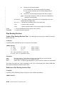
Selecting File Types
You can choose from four types of files when building the files for your store system: random, direct,
keyed, and sequential. You create all files using variations of the CREATE statement and accompanying
parameters.
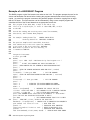
Random
Random files have fixed record lengths. The system uses the last two bytes in each record for the
carriage return and line feed characters (CR/LF). The system pads the data space between the last field
of the record and the CR/LF.
Random files offer random access, which allows direct access to any record in a file. This ability makes
random and direct files an ideal type for files that can be referenced by a relative record number. If you
need a name or a specific number (such as a telephone number) to reference a record, use Keyed File
Services. You ensure that the number of bytes occupied by the field delimiters and CR/LF do not exceed
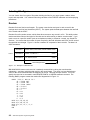
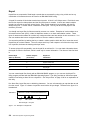
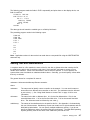
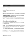
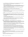
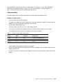
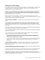
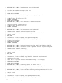
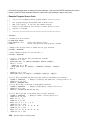
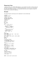
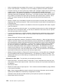
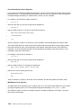
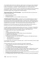
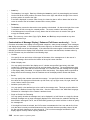
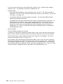
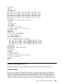
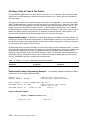
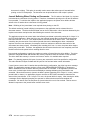
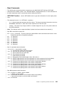
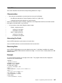
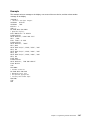
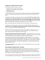
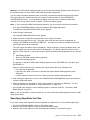
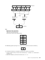
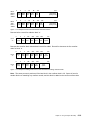
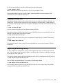
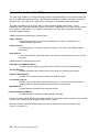
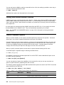
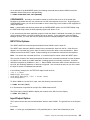
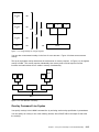
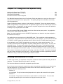
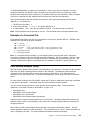
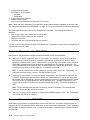
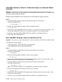
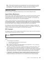
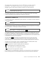
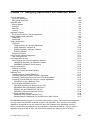
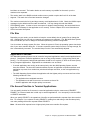
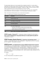
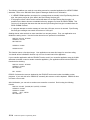
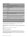
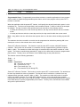
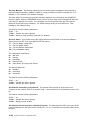
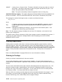
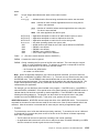
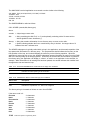
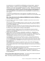
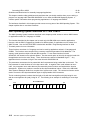
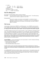
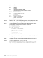
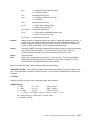
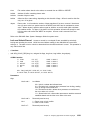
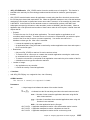
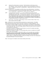
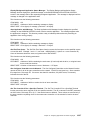
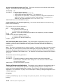
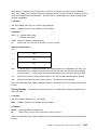
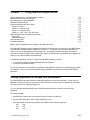
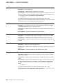
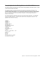
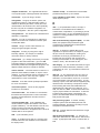
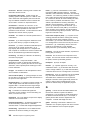
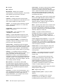
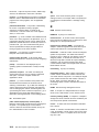
the specified record length. Figure 2-1 shows a random file composed of three records. The data is in
ASCII characters.
FILE.1
RECORD 1
"FIELD ONE","FIELD TWO","FIELD THREE" CR/LF
RECORD 2
"FIELD 1","FIELD 2"," "
CR/LF
RECORD 3
111,222,3.3,444,5.5
CR/LF
Record lengths fixed
Figure 2-1. Example of a Random File
IBM 4680 BASIC locates each record of a randomly accessed file by taking the record number,
subtracting 1, and then multiplying that result by the record length. The result is a byte displacement
value for the record measured from the beginning of the file. Records can span sectors. You must
specify the record to be accessed in each READ#, PRINT#, or WRITE# statement executed. The
following BASIC program creates the random file diagrammed in Figure 2-1.
CREATE
WRITE
WRITE
WRITE
CLOSE
END
2-2
"FILE.1" RECL 40 AS 2
A$ = "FIELD ONE"
B$ = "FIELD TWO"
C$ = "FIELD THREE"
D$ = "Field 1"
E$ = "Field 2"
F$ = ""
G% = 111
H% = 222
I = 3.3
J% = 444
K = 5.5
#2,1; A$, B$, C$
#2,2; D$, E$, F$
#2,3; G%, H%, I, J%, K
2
4690 Store System: Programming Guide
The following program reads the first three fields from record 3 in FILE.1.
IF END #20 THEN 200
OPEN "FILE.1" RECL 40 AS 20
READ #20,3; FIELD1%, FIELD2%, FIELD3
PRINT FIELD1%, FIELD2%, FIELD3
200 END
The preceding program results in the following output.
111
222
3.3
For applications written for the terminal, you must use the WRITE statement to send data to a random file.
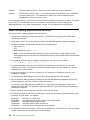
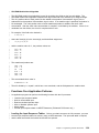
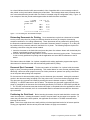
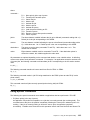
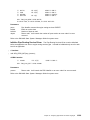
Direct
Direct files are like random files except that direct files contain no delimiting characters (quotes, commas,
and CR/LF). Direct files contain no data formatting information. Because of this, you must specify a
special format string when you want to access the data in a direct file. See “Performing File Functions” on
page 2-18 to learn more about accessing a direct file.
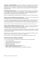
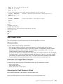
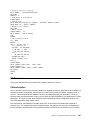
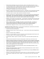
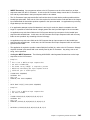
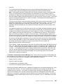
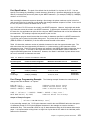
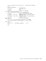
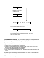
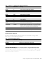
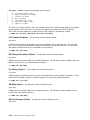
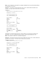
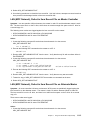
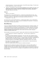
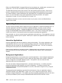
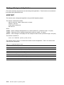
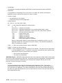
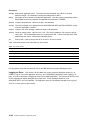
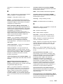
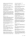
The following program creates a direct file named DIRECT.DAT that consists of one 15-byte record. The
variable D represents the format string used in the WRITE FORM# statement.
STRING A,
INTEGER*2
REAL C
D
B
CREATE
"DIRECT.DAT" DIRECT
A = "ABC"
B = 32767
C = 27.35
D = "C3, I2, R"
WRITE FORM D; #3,1; A,B,C
RECL 15
AS 3
LOCKED
CLOSE 3
END
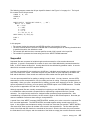
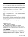
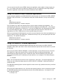
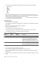
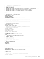
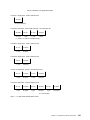
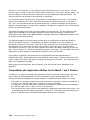
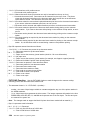
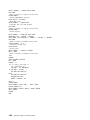
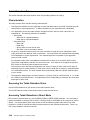
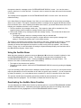
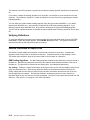
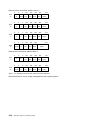
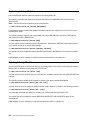
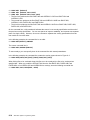
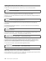
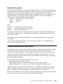
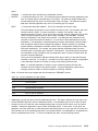
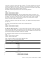
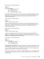
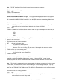
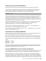
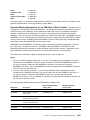
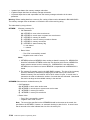
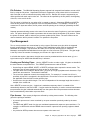
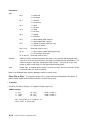
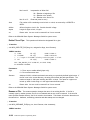
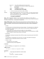
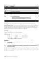
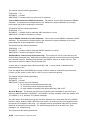
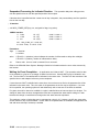
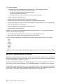
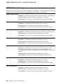
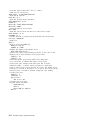
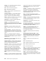
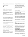
Figure 2-2 shows the direct file created by the preceding program. The data in the figure is in
hexadecimal.
RECORD 1
414243FF7F42000000000000003527
ABC
32767
27.35
Record length = 15 bytes
Figure 2-2. Example of a Direct File
Chapter 2. Managing Files
2-3
Keyed
Keyed files are composed of fixed-length records that are accessed by using a key, which can be any
combination of characters that can be used in an IBM 4680 BASIC string.
A keyed file consists of blocks that contain keyed records. A block is a 512-byte sector. Each block uses
the first four bytes for chain pointers and the next 508 bytes for records. A block can contain multiple
records, but records are not split across blocks. Each record contains its key and data, with the key
always being first. A record can be a maximum of 508 bytes. The key can be as many bytes of the
record as you need.
You should use keyed files for files accessed by a name or a number. Examples of such numbers are a
Universal Product Code (UPC), a label, a telephone number, or a check authorization number. These
types of names and numbers do not have any contiguous nature and are random in their occurrence. You
can use numbers that have a contiguous nature to access a random or direct file.
You access keyed files by hashing the key to obtain a relative position within the file to locate the record.
Keyed files do not have indexes. The more unique each key is with respect to all of the other keys used
in a keyed file, the better the hashing technique works.
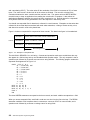
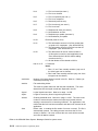
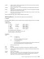
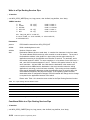
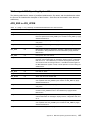
To access a keyed file sequentially, use the keyed file as a direct file. You can obtain information about
the keyed file from the first block, which is used only for control information. The format of this first block
is:
Relative Byte
Offset (in Decimal)
Number of Bytes
(in Decimal)
Keyed File
Information
42
4
Number of blocks in keyed file
46
2
Keyed record size
48
4
Randomizing divisor
54
2
Key length
56
4
Chaining threshold
You can create keyed files directly with an IBM 4680 BASIC program, or you can use the Keyed File
Utility program provided with the IBM 4690 Operating System. The utility provides an efficient two-pass
method of converting a direct file into a keyed file. See “Keyed Files” on page 2-28 for an explanation of
this utility.
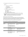
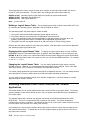
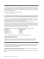
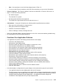
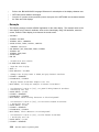
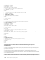
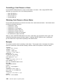
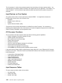
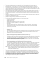
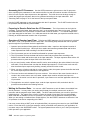
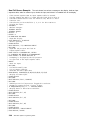
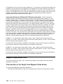
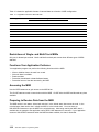
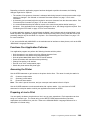
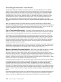
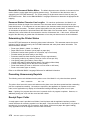
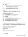
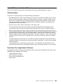
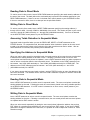
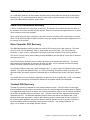
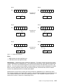
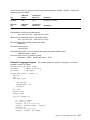
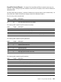
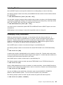
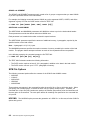
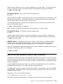
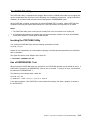
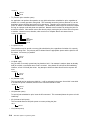
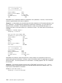
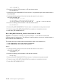
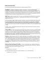
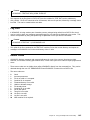
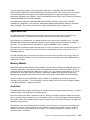
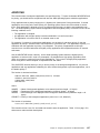
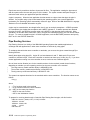
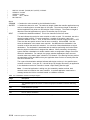
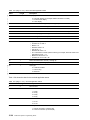
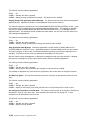
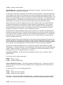
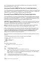
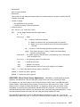
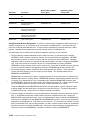
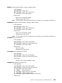
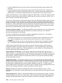
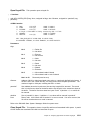
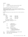
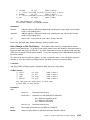
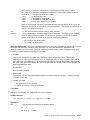
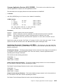
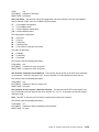
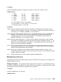
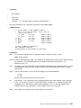
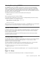
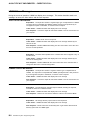
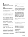
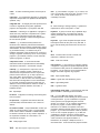
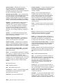
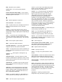
Like direct files, keyed files use no delimiting characters. You use a format string to map the data to and
from the record. Figure 2-3 shows a keyed file record with a 19-byte length. The data in the figure is in
hexadecimal.
RECORD 1
4B455931414243FF7F42000000000000003527
key1
ABC 32767
Record length = 19 bytes
Figure 2-3. Example of a Keyed File
2-4
4690 Store System: Programming Guide
27.35
The following program creates the 19-byte keyed file shown in the Figure 2-3 on page 2-4. The keyed
file consists of one 19-byte record.
STRING A,
INTEGER B
REAL C
D,
KEY
CREATE POSFILE "KEYFILE.DAT" KEYED 4 , , , 200 \
RECL 19 AS 4 LOCKED
KEY = "key1"
A = "ABC"
B = 32767
C = 27.35
D = "C4, C3, I2, R"
WRITE FORM D; #4; KEY,A,B,C
CLOSE 4
END
In this program:
¹ The numeral 4 after the reserved word KEYED specifies a key length of 4 bytes.
¹ The three commas after the numeral 4 indicate that no randomizing divisor or chaining threshold value
is specified; therefore, the defaults are used.
¹ The numeral 200 after the three commas specifies a total of 200 records in the keyed file.
¹ The variable D represents the format string used in the WRITE FORM# statement.
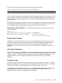
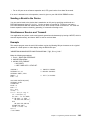
Sequential
Sequential files are composed of variable-length records accessed in a first-record-to-last-record
sequence. A record in a sequential file consists of one or more fields delimited by commas between the
fields. A CR/LF follows the last field. A string data field is also delimited by quotation marks. A numeric
data field is converted to an ASCII representation.
A record in a sequential file can contain up to 64 KB long. Individual record lengths vary according to the
size of the fields in the record. Each field occupies only the number of bytes required by the data in the
field and the delimiters. Data records are written one after another and can span disk sectors.
You can open sequential files for reading or writing but not for both. You can, however, use two OPEN
statements to access a sequential file, one for reading and one for writing. Each open processes the file
sequentially. When you open a sequential file for reading, you start at the beginning of the file. When you
open a sequential file for writing, you must specify the APPEND option in the OPEN statement. The data
that you write is appended to the end of the existing file.
Although sequential files are normally accessed from beginning to end, IBM 4680 BASIC provides a way
to re-establish a reference within a sequential file for reprocessing a sequential file from a saved
reference. You might find this useful as a checkpoint when processing large sequential files. After
re-establishing a sequential file reference, the file access is again a next-record sequence. Note that you
cannot re-establish a reference when writing to a sequential file.
A special form of the WRITE command, WRITE MATRIX, enables you to write a record to a sequential file
from a terminal application. The WRITE MATRIX command supports writing records longer than 512
bytes. It also supports the simultaneous writing of records from more than one terminal. WRITE MATRIX
uses several file writes to place all the data in the record in the sequential file. The first write specifies
some of the fields and filler data for the remainder of the record. After the first write, the record contains
the fields that fit into 512 bytes, and the remainder of the fields are empty (the record is filled with commas
Chapter 2. Managing Files
2-5
and a terminating CR/LF). The other writes fill the remainder of the fields in increments of 512 or fewer
bytes. The entire record is locked until all of the writes are finished. The record is unlocked if the
connection between the store controller and the terminal is lost. The system writes a WRITE MATRIX
record this way to keep an application from reading the record until it is complete. It also allows an
application to determine whether the record has been completed or not. Records placed in a sequential
file by WRITE MATRIX are not guaranteed to be in the sequence in which they occur.
You should use sequential files for data that is collected in a serial manner. Examples are the sales data
collected in the terminal that is associated with each sales transaction, a listing of events as they occur,
and data to be saved in a file to be printed later.
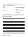
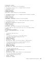
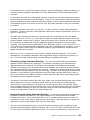
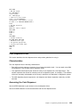
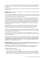
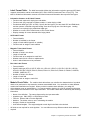
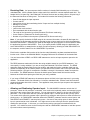
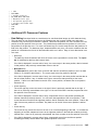
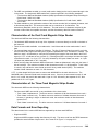
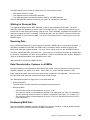
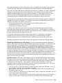
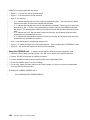
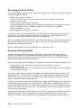
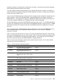
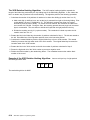
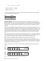
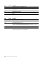
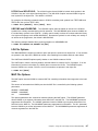
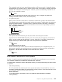
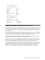
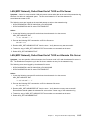
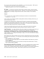
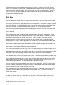
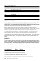
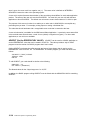
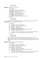
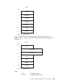
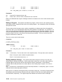
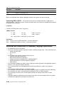
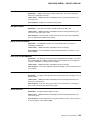
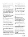
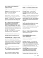
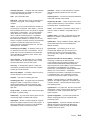
Figure 2-4 shows a sequential file composed of three records. The data in the figure is in hexadecimal.
FILE.2
RECORD 1
"FIELD ONE","FIELD TWO","FIELD THREE"CR/LF
RECORD 2
"FIELD 1","FIELD 2"," "CR/LF
RECORD 3
111,222,3.3,444,5.5CR/LF
Record lengths vary
Figure 2-4. Example of a Sequential File
The third field in RECORD 2 is a null string. Commas and quotation marks serve as delimiters but may
also appear in a field as long as they are imbedded within quotation marks. The only exception is that a
quotation mark followed by a comma must serve as a string delimiter. The following program creates the
sequential file diagrammed in Figure 2-4.
CREATE
WRITE
WRITE
WRITE
CLOSE
END
"FILE.2" AS 2
A$ = "FIELD ZERO, ONE"
B$ = "FIELD TWO"
C$ = "FIELD THREE"
D$ = "Field 1"
E$ = "Field 2"
F$ = ""
G% = 111
H% = 222
I = 3.3
J% = 444
K = 5.5
#2; A$, B$, C$
#2; D$, E$, F$
#2; G%, H%, I, J%, K
2
The three WRITE# statements correspond to the three records, and each variable corresponds to a field.
When you access sequential files, each field is read one at a time from the first to the last. The READ#
statement considers a field complete when it encounters a comma or CR/LF for numeric fields, and a
quotation mark followed by a comma or carriage return for string fields.
2-6
4690 Store System: Programming Guide
The following program reads the fields in FILE.2 sequentially and prints them on the display device, one
field for each line.
IF END #19 THEN 100
OPEN "FILE.2" AS 19
FOR I% = 1 TO 11
READ #19; FIELDS$
PRINT FIELDS$
NEXT I%
100 END
The data type should match the variable type on a field-by-field basis.
The preceding program results in the following output:
FIELD
FIELD
FIELD
Field
Field
ONE
TWO
THREE
1
2
111
222
3.3
444
5.5
Note: Applications written for the terminal can send data to a sequential file using the WRITE MATRIX
statement only.
Naming Files and Subdirectories
A complete name for a file contains the name of the file, the disk or diskette drive that contains the file,
the subdirectory path for the file, and the node name if you have MCF and want to access a file on
another store controller. Some of the information in the file name is optional. If it is not present, the
system either treats it as blanks or substitutes default values. Generally, you should specify values rather
than rely on defaults.
The general format for a complete file name is:
nodename::\drivename:\subdirectory\filename.extension
where:
nodename
The name used to identify a store controller on the network. You can use this name to
access files on a different store controller on the LAN. The nodename must be followed
by two colons (::). See “Using Node Names to Access Files” on page 2-18 for more
information.
drivename
The name for the disk or diskette drive. A is for the first diskette drive. B is for the
second diskette drive. C is for the first fixed disk drive. D is for the second fixed disk
drive. The drivename must be followed by one colon (:).
subdirectory
The names of the subdirectories in the path for this file. See Appendix A for determining
the use of these names. Subdirectory names can contain one to eight characters and are
delimited by backslashes. You can specify multiple subdirectory names. If you do not
specify a subdirectory name, the system uses the root directory. The IBM 4690 Operating
System generally uses the first level of the subdirectory and not the root.
Chapter 2. Managing Files
2-7
filename
The actual name of the file. The file name can contain one to eight characters.
extension
The extension of the file name. You use the extension as an additional set of characters
to uniquely define a file. The extension can contain one to three characters and is
separated by a period from the file name.
In an application program, you should use a logical name to represent the complete file name. The logical
name is easier to use and allows the file to be placed on the desired drive without changing the
application program. See “Using Logical Names” on page 2-11 for information on logical names.
Rules for Naming Subdirectories and Files
The general rules for naming subdirectories and files are:
1. Do not start a subdirectory or file name with ADX. The prefix ADX is reserved for the IBM 4690
Operating System files.
2. Avoid using a name for a file that matches a name of an IBM 4690 Operating System command.
3. Characters allowed in subdirectories, file names, and extensions are:
¹ Uppercase A–Z
¹ 0–9
¹ Special characters @ # ( ) { }
Note: Do not use these special characters in the first, fourth, fifth, or eighth position of a file
name because these conflict with Host Command Processor (HCP) and input sequence table build
file names.
4. The following characters are not allowed in subdirectories, file names, and extensions:
? * : . $ & _ ; , [ ] ! + = < > " - / \ │
5. In terminal applications, you can use a maximum of 24 characters in a statement for a file name,
including its extension. This maximum includes a mandatory node name (for example, R::) of three
characters prior to all file names.
6. In the store controller, you can use a maximum of 127 characters in a statement for a file name,
including its extension.
7. File names with a .BSX extension are symbol files for programs with the same file name.
8. The file extension .$$$ represents a temporary file that the data distribution application (DDA) uses
when distributing an entire file across the LAN (MCF Network).
For example, when distributing the file ABC.DAT to a remote node, the application creates a new
version named ABC.$$$. The application deletes the ABC.DAT copy and renames the temporary file
(ABC.$$$) to ABC.DAT.
9. The file extension .C0 is a temporary input file to the Keyed File Utility.
10. All ADXxxxxx names are not files or subdirectories. Some ADX file names represent functions, pipes,
processes, or node names. For example:
ADXFILES
ADXLNDAP
ADXLND1L
ADXLXCCN::
ADXLXAAN::
Function for a forced close
Pipe indicating that a store controller is the acting master
LAN distribute per update process
LAN node name for store controller CC
LAN node name for acting master store controller
11. All 4690 files are found in directories. Some files are placed in the root directory, but most are located
in subdirectories that are one level below the root directory.
2-8
4690 Store System: Programming Guide
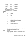
12. 4690 Operating System subdirectory names have the following general form:
ADX_yzzz
Where:
y
= Intended user of the subdirectory:
I
S
K
U
=
=
=
=
IBM applications
Operating system
Store Systems Regression Tester
User
zzz = Contents of the subdirectory:
PGM = Active programs and associated data
DT1 = Data files
DT4 = Data files
MNT = Maintenance modules
BUL = Backup level of maintenance modules
13. The following subdirectories do not follow the 4690 Operating System naming conventions:
ADX_APGM User subdirectory that allows application data files to be system-mirrored files
ADX_BSX
Subdirectory for .BSX symbol files that are not currently being used
ADX_IOSS 4690 Operating System print spooler data files and control blocks
Use these rules for file names and extensions.
Part of determining how to name a file is knowing the intended use of the file and the subdirectory
containing the file. Generally, files are either programs or data. Some data files are really a logical
extension of programs such as files that contain messages, screen definitions, or personalization values.
Other data files contain data that is referred to or modified as a result of the sales activity.
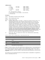
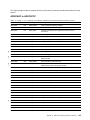
Table 2-1 describes the naming rules for the various types of files and subdirectories.
Table 2-1 (Page 1 of 2). Naming Files on the IBM 4690 Operating System
Subdirectory
File Name
Extension
ADX_IPGM
ADX_IMNT
ADX_IBUL
¹ Must be 8 characters.
¹ First 3 characters must be the same as
defined in configuration and cannot be
ADX.
¹ Last character must be D, F, L, O, S, V,
or W. See Table 2-2 on page 2-10.
¹ Any of the valid name characters, but
do not use special characters in the 5th
character position.
ADX_IDT1
¹ Must be 8 characters.
¹ First 3 characters must be the same as
the files in ADX_IPGM.
¹ Other 5 characters can be any of the
valid name characters.
¹ Should be DAT.
¹ Exception might be files that are only
referred to by the application and HCP using
logical file name (LFN).
ADX_IDT4
¹ Must be 8 characters.
¹ First 3 characters must be the same as
the files in ADX_IPGM.
¹ Other 5 characters can be any of the
valid name characters.
¹ Should be DAT.
¹ Exception might be files that are only
referred to by the application and HCP using
LFN.
Must be 3 characters and must be determined
according to the file use table based on the last
character of the file name (see Table 2-2 on
page 2-10).
Chapter 2. Managing Files
2-9
Table 2-1 (Page 2 of 2). Naming Files on the IBM 4690 Operating System
Subdirectory
File Name
Extension
ADX_SPGM
ADX_SMNT
ADX_SBUL
ADX_SDT1
These subdirectories are for use only by the
IBM 4690 Operating System and must not
contain any application files.
ADX_UPGM
ADX_UMNT
ADX_UBUL
See note below.
Must be 4 characters.
Must be 3 characters and must be determined
according to the file use table (see Table 2-2 on
page 2-10). The last character of the file name
is not used to determine the extension for these
subdirectories.
ADX_UDT1
See note below.
Must be 4 characters.
Must be 3 characters according to what type of
translation should be done by HCP when
exchanging this file with the host:
ASC = ASCII to EBCDIC
BIN = No translation
XLT = User translation
Note: To be exchanged with the host processor through HCP, names in the ADX_UPGM, ADX_UMNT,
ADX_UBUL, and ADX_UDT1 subdirectories must follow these guidelines. If the files in these
subdirectories are used only for local use, such as for program development, follow the general file
naming rules. When local files need to be exchanged with the host, you can rename them according to
the renaming rules for these subdirectories.
Table 2-2 (Page 1 of 2). File Use Table
File Name
Character
Extension
Intended File Use
A
A86
Assembler source code
B
BAS
4690 source code
C
C
C source code
D
DAT
Product control files
E
F
Reserved; do not use
DAT
G
H
Messages, input sequence tables, and similar files
Reserved; do not use
H
I
C source code include files
Reserved; do not use
J
J86
4690 source code include files
K
L86
Library files
L
286
4690-executable file
M
MAP
Linkage editor map file
MF
DAT
Data files (messages)
N
INP
Linkage editor input file
O
OBJ
Relocatable object file
P
LST
Language translator listing file
Q
LIS
4690 interlisting file
R
LIN
4690 line number file
2-10
4690 Store System: Programming Guide
Table 2-2 (Page 2 of 2). File Use Table
File Name
Character
Extension
Intended File Use
S
DAT
Display Manager screen files
T
SYM
Linkage editor symbol table file
U
BSX
Symbols file
V
OVR
4690-executable overlay file
W
SRL
Shareable runtime libraries
X
XRF
Cross-reference file
Y
SYS
4690 non-relocatable file
Z
BAT
Batch files
For example, the LOAD ALL TERMINALS function uses these files:
ADXCS20L.286
ADXCS3AS.DAT
ADXCS3MF.DAT
The executable module or program
The Display Manager screens for running the utility interactively
The message file used by the utility
Using Logical Names
A logical name is a way to abbreviate a file name. You can use logical names to represent either the
entire file name (LFN type) or the drive and subdirectory path of the file name (LDSN type). You can use
LFN, which represents the logical file name as the entire file name. You can use LDSN, which represents
the logical drive and subdirectory name, as the drive and subdirectory path part of the file name.
Table 2-3 illustrates the use of these terms:
Table 2-3. LDSN and LFN Terms
Type
General Form for
Using This Type
Example of a Name
Using This Type
LDSN
LDSN:filename.extension
ADX_IDT1:EALABCDE.DAT
LFN
LFN
C:\ADX_IDT1\EALPQRST
The operating system provides LDSN forms of logical names for all of the supported subdirectories.
Table 2-4 lists the LDSNs.
Table 2-4 (Page 1 of 2). System-Provided LDSN Format
LDSN
for DRIVE: \SUBDIRECTORY\
ADX_SPGM:
C:\ADX_SPGM\
ADX_SMNT:
C:\ADX_SMNT\
ADX_SBUL:
C:\ADX_SBUL\
ADX_SDT1:
C:\ADX_SDT1\
ADX_IPGM:
C:\ADX_IPGM\
ADX_IMNT:
C:\ADX_IMNT\
ADX_IBUL:
C:\ADX_IBUL\
ADX_IDT1:
C:\ADX_IDT1\
ADX_IDT4:
C:\ADX_IDT4\
Chapter 2. Managing Files
2-11
Table 2-4 (Page 2 of 2). System-Provided LDSN Format
LDSN
for DRIVE: \SUBDIRECTORY\
ADX_UPGM:
C:\ADX_UPGM\
ADX_UMNT:
C:\ADX_UMNT\
ADX_UBUL:
C:\ADX_UBUL\
ADX_UDT1:
C:\ADX_UDT1\
Defining Logical File Names
You can create, display, or modify logical file names during the configuration process. Configuration
screens allow you to define three types of logical file names:
¹ System files
¹ Application files
¹ User files
Note: You must not use the same name for any type of communications line or SNA link that you use for
any system, application, or user logical file name.
System Logical File Names: System logical file names are reserved names used for operating
system files and subdirectories. The ADXDAxyF.DAT file (where xy is the store controller ID) in the
ADX_SPGM subdirectory contains the system logical file names.
Using the configuration screens, you can change the disk drive name defined in the LFN forms of these
system files. You cannot change the LDSN forms of the system logical names and you cannot add new
system logical names.
Application Logical File Names: An IBM licensed program or another program defines
application logical file names. The ADXDCxyF.DAT file (where xy is the store controller ID) in the
ADX_SPGM subdirectory contains the application logical file name.
Use the configuration screens to change the disk drive name specified in the LFN form of the application
logical names. You cannot change the LDSN forms of the application logical names and you cannot add
new application logical names.
Defining User Logical File Names: You can completely define user logical file names through
configuration. You can define these file names as any allowed logical names that are not reserved by the
operating system or an IBM licensed program. You can define either LFN or LDSN types of user logical
names. The ADXDExyF.DAT file (where xy is the store controller ID) in the ADX_SPGM subdirectory
contains the user logical file names.
You can define logical names whenever you choose, but the changes do not become effective until you
activate them. To activate logical names, use the Supplemental Diskettes.
|
|
|
|
To have more displayable characters available on your store controller applications, define the logical
name disp4680 to any value. Setting a value causes 4690 OS to use the 4680 Controller Video Display
Character set. Refer to the IBM 4680 Basic Language Reference for a description of the 4680 and 4690
Controller Video Display Character Sets.
2-12
4690 Store System: Programming Guide
Logical File Names on a LAN (MCF Network) System
Logical file names make accessing files on other store controllers on the LAN (MCF Network) easier by
letting you abbreviate lengthy file names. The system expands your abbreviated file name to the full file
name when accessing the file.
For example, MYITEMS is a logical name used by your sales application for an item record file. The
system expands this name to its full file name, ADXLXAAN::C:\ADX_IDT1\MYITEMS.DAT, when another
node references MYITEMS. (Refer to the IBM 4690 Store System: User’s Guide for a discussion of nodes
and node IDs.) In this example, the expanded name gets the version of the MYITEMS.DAT file that is on
the master store controller (ADXLXAAN::), on the C drive (C:), in the ADX_IDT1 subdirectory
(\ADX_IDT1\).
You can use a logical name to refer to a unique node, a unique subdirectory, or to a file. For example,
ADX_IPGM: is a logical name for the subdirectory C:\ADX_IPGM\. Likewise, the logical name
ADX_IPGM:MYMOD.286 refers to a module whose full file name is C:\ADX_IPGM\MYMOD.286.
More than one logical name can refer to the same file. For example, if you define both ABC and DEF as
logical names for C:\ADX_UPGM\YOURMOD.286, any reference to ABC or DEF translates to the same
file name.
You could then define ABCD to be the logical name for the file
ADXLXCCN::C:\ADX_UPGM\YOURMOD.286, and ABCDE to be the logical name for the file
ADXLXAAN::C:\ADX_UPGM\YOURMOD.286. A reference to ABC or DEF would look for YOURMOD.286
only on the local controller. A reference to ABCD would look for the file only on the store controller node
with the ID of CC. A reference to ABCDE would look for the file on the acting master store controller
(ADXLXAAN::) wherever it is and whatever its ID is. If there was no acting master at that time, the system
returns a file error message.
Every distributed file must have a logical name defined in the application logical names file or the user
logical names file. The format of the logical name in the Logical Names File is:
For a compound file:
ADXLXAAN::drive\subdirectory\filename.extension
Logical name format for a mirrored file:
ADXLXACN::drive\subdirectory\filename.extension
Note: The system allows only one level of a subdirectory in a logical name expansion.
You can access prime versions of compound or mirrored files to read, write, delete, or rename files.
However, you can only read an image version. You cannot access image versions of distributed files that
are distribute at close. If you try to write, delete, rename or lock an image version of a distributed file, you
will receive an error message.
Logical Names Table
The operating system uses a single table of logical names for its files, store controller node names,
subdirectories, and for most I/O devices such as printers and displays. A default logical names table is
supplied with the operating system at installation. The system adds application and user logical names
from the application and the user logical names files to the system table at IPL. (See “Using Logical
Names” on page 2-11 for information on application and user logical names files.)
Chapter 2. Managing Files
2-13
These application files can be unique for each store controller so the logical names table can also be
unique for each store controller. The files used in the building of the logical names table are:
ADXDAxyF.DAT
ADXDCxyF.DAT
ADXDExyF.DAT
Operating system logical names file (initially the system default table)
Application logical names file
User logical names file
Note: xy is the node ID.
Building a Logical Names Table: The operating system builds a logical names table at IPL time
by combining the operating system, application, and user logical file names.
The operating system uses these steps to create the table:
1. The system starts with the default operating system logical names file.
2. The system adds any new names from the application logical names file.
3. If any of the application logical file names duplicate an operating system logical file name, the
operating system logical file name is overlaid with the application logical file name.
4. The system uses the user logical names file to add new names or overlay existing names.
Because the user logical names file is the last to be scanned, it has precedence over both the application
and operating system logical names files.
Displaying the Logical Names Table: To display the logical names table, from the SYSTEM
MAIN MENU, select the Command Mode option by typing 7 and press Enter. In the root directory, type
DEFINE -S -N (S for system, N for logical names table) and the system displays the logical names tables.
To display the logical names table one screen at a time, you can use the MORE parameter. For example:
C:>define -s -n |more
Changing the Logical Names Table: You can change application logical names using the
DEFINE command. However, it is recommended that these names not be changed. Refer to the IBM
4690 Store System: User’s Guide for a description of the DEFINE command.
You cannot change application logical names through the configuration process. You can change the disk
drive identification for some of these names to provide disk space and better performance.
You can define user logical names during store controller configuration. Use these names to override
application logical names if desired.
Accessing Distributed Files in Store Controller and Terminal
Applications
This section shows how to access distributed files from terminal nodes using logical names. The section
uses an example to show how to define the file in the user logical names table and how to distribute the
file to other nodes.
The example shows how a terminal user program can access a user-defined distributed file called
MYFILE.DAT. The file is a compound file that is Distribute Per Update. The system distributes a
compound file to all store controllers. The example shows how to put the prime version of the file on drive
D of the master store controller in the ADX_IDT4: directory.
In the example, the user program reads the local image version of the file, which reduces response time
and improves performance. To update the file, the user program opens the prime version of the file on
the master store controller.
2-14
4690 Store System: Programming Guide
Setting up the file on the LAN (MCF Network) and opening the file in the user program is a three-part
process. This process consists of defining the file, creating it, and accessing it through the user program.
Step 1. Define the File: Define the file MYFILE.DAT in the user logical names tables. You must
define the file in the logical names file on each eligible store controller. (Refer to the IBM 4690 Store
System: Planning, Installation, and Configuration Guide for information on worksheets and designating
eligible LAN store controllers.)
When the file is defined in the user logical names tables, the table will have two entries placed in it for the
MYFILE.DAT user file as follows:
1
2
$YFILE = D:\ADX_IDT4\MYFILE.DAT
! Local version
! Prime version
MYFILE = ADXLXxxN::$YFILE
where the actual node ID of the current acting master store controller replaces xx.
The first entry gives the path to the local image version of the file for each store controller (for example, on
drive D in the ADX_IDT4 subdirectory, with the file name of MYFILE.DAT). Open this file when you want
to access the local version of the distributed file. Your application can only read this version.
The second entry gives the path to the prime version of MYFILE on the master store controller
(ADXLXxxN::). Open this file when you want to update the prime version of the distributed file.
|
|
|
|
|
|
|
|
|
|
|
When the prime version of MYFILE.DAT is updated or deleted, DDA updates the local image versions on
the other nodes using the LFN $YFILE. Since each eligible store controller on the LAN has its own
definition of $YFILE, the drive and subdirectory of the local image versions may be different from the path
of the local version on the master store controller.
Note: When updating any distributed file named MYFILE.DAT using the LDSN or complete file name
formats, DDA will continue to use the LFN $YFILE on the other nodes if LFN MYFILE is defined on
the master store controller. If the LFN $YFILE is not defined on the other nodes, DDA will assume
$YFILE is the expanded full file name and place the updates in the file C:\$YFILE on the other
store controllers.
Attention: Undesirable operations may be performed on the image versions if two or more files named
MYFILE.DAT exist in separate directories on the master store controller.
To define the file in the logical names file, perform the following steps at the master store controller. You
must repeat these steps for each eligible store controller on the LAN.
1. On the SYSTEM MAIN MENU screen, type 4 and press Enter.
2. When the INSTALLATION AND UPDATE AIDS screen appears, type 1 and press Enter.
3. On the CONFIGURATION screen, type 2 and press Enter. When prompted “Are you configuring for a
LAN system?”, type Y.
4. When the CONTROLLER CONFIGURATION screen appears, press Enter.
5. At the next configuration screen, select a store controller by moving the highlighted cursor to the
appropriate node ID and press Enter. You must return to this screen to select an ID for each eligible
store controller.
6. When the next CONTROLLER CONFIGURATION screen appears, use the Tab key to move the
cursor next to User Logical File Names. Type X and press Enter.
7. When the USER LOGICAL FILE NAMES screen appears, type 1 and press Enter.
8. On the same screen in the file name window, enter the user logical name to be used to access this
file. (The sample problem uses MYFILE as the logical name.) Press Enter.
Chapter 2. Managing Files
2-15
9. On the DEFINE LOGICAL FILE NAMES screen, type in the expanded name to define the logical
name for the distributed user file, and press Enter. The sample problem uses
ADXLXAAN::D:\\ADX_IDT4\MYFILE.DAT.
The node name ADXLXAAN:: defines this file to be on the master store controller. The D:\\ defines it
on drive D and the double backslash ensures that drive D is accessed while operating in any
subdirectory. The remaining portion of the node name, ADX_IDT4\MYFILE.DAT, is the standard
subdirectory/filename.extension naming convention.
10. Press F3 to go back through the configuration screens until you return to the CONTROLLER
CONFIGURATION screen. On this screen, select another controller node ID.
11. Repeat steps 5 through 10 until you have defined the user logical name MYFILE on all store
controllers on your network.
12. Press F3 again to back out of the configuration process until you get to the CONFIGURATION screen.
On this screen, type 5, and press Enter.
13. On the next screen, type 2 (Controller Configurations) and press Enter to activate the changes just
made.
14. After you have verified, distributed, and activated the changes, you must IPL the controllers. To do
this, press the SysRq key, then type C to select controller functions. On the next screen, type 2
(Controller functions) again and press Enter. On the next screen, type 9 (Load Controller Storage)
and press Enter.
In the highlighted box that appears, type an asterisk (*) to IPL all store controllers. Answer Y to the
prompt about stopping background programs.
If you do not want background programs stopped now, press F3 to process, and wait until all
background processing is finished before continuing. Before the next steps can be completed, the
controllers must be IPLed. You can choose the time to do that.
Step 2. Create the File: Create the file MYFILE.DAT in one of the following ways:
¹ Create a user-written program that creates a POS file statement. For example, if you are using an
IBM 4680 BASIC program, include a CREATE POSFILE statement. Be sure the statement includes
the parameters COMPOUND and PERUPDATE to give the file the correct attributes.
¹ At the master store controller from the host specifying either CREATE or CLOD (Create and Load)
using ADCS. Be sure you specify the correct attributes on the CREATE or CLOD statements (that is,
SHARE=NO, VOL=3) to get the correct distribution attributes.
¹ Use another supported means instead of ADCS to send HCP commands to create the file.
¹ Use the 4690 Operating System COPY command to copy the file from a diskette to the fixed disk.
You can create the version on the diskette as a distributed file and then the proper attributes are
transferred during the copy process. If you copy a nondistributed version, use the Distributed File
Utility (DFU) to define the file as distributed after you copy it. Refer to the IBM 4690 Store System:
User’s Guide for more information about the DFU.
The file is distributed to the proper store controllers by the DDA. Refer to the IBM 4690 Store System:
User’s Guide for more information.
Step 3. Access the File from the User Program: The user program uses the MYFILE user
logical name to open the prime version of MYFILE.DAT on the master store controller for a READ or
READ-WRITE.
The program uses the $YFILE file to open the local version of the file on the store controller that is
supporting the TCC Network that the terminal is on.
2-16
4690 Store System: Programming Guide
You can open the local file only for READ, because an application cannot update an image version of a
file. If you create the file with a file attribute of distribute at close, the application cannot open $YFILE
because an application cannot read a file with the distribute at close attribute.
Using File Names in Store Controller Applications
In store controller applications, the IBM 4680 BASIC statements that use file names are OPEN, CREATE,
RENAME, SIZE, and CHAIN. For all statements except the CHAIN statement, use any of the following
formats:
LFN
LDSN:filename.extension
drivename:\subdirectory\...\filename.extension
The LFN allows you to place the referenced file on any drive without modifying the application. You
should define the LFN to be a complete file name with the subdirectory being ADX_IDT1. (There should
be an ADX_IDT1 subdirectory on each drive.) If you use the LDSN format, you should define the LDSN
as a drive and subdirectory path. You can use the complete file name format for cases that are not
supported by the LFN or LDSN format, such as a special testing environment.
When you are using the CHAIN statement, use a file name and extension with a drive and subdirectory, or
use the LDSN for the drive and subdirectory. Whichever format you use, you must specify the drive and
subdirectory. The possible formats are:
LDSN:filename.extension
drivename:\subdirectory\...\filename.extension
Using File Names in Terminal Applications
In terminal applications, the IBM 4680 BASIC statements that use file names are OPEN, CREATE,
RENAME, LOAD, SIZE, and CHAIN. Each of these statements requires that the node name R:: precede
the file name.
When using the OPEN, CREATE, RENAME, or LOAD statements, use the LFN format for the file name.
This allows you to place the referenced file on any disk drive without modifying the application. You
should define the logical file name to be a complete file name with the subdirectory being ADX_IDT1.
(There should be an ADX_IDT1 subdirectory on each disk drive.) An example of a file name using this
format is:
R::EALABCDE
Note: The LFN represents all of the file name except the R:: node name. The terminal application can
access any drive except the diskette drives for OPEN, CREATE, or RENAME. CHAIN and LOAD can
access any drive.
The IBM 4690 Operating System converts logical file names to their fully qualified names that you defined
in configuration.
When using the CHAIN statement, use a file name and extension without a drive or subdirectory because
the IBM 4690 Operating System automatically uses the ADX_IPGM subdirectory. An example of a file
name using this format is:
R::EALPQRSL.286
Chapter 2. Managing Files
2-17
Using Node Names to Access Files
To access a file on another store controller, an application must use a file specification that includes the
node name when opening a file. (Refer to the IBM 4690 Store System: User’s Guide for a discussion of
nodes and node IDs.) If file specification does not include the node name, the request tries to locate the
file on the local store controller.
The complete file specification should follow the format:
nodename::pathname\filespec
Every node name has the form ADXLXxyN:: where xy is the store controller ID. Note that you end node
names with a double colon. Use a single colon to indicate physical devices on the same controller, such
as C:, D:, LPT1:, COM1:, and so on. Use the double colon to indicate different nodes on the network.
R:: is required in a terminal application when addressing an external (any controller) file. For example,
when opening the XYZ file on the file server, the terminal application refers to this file as R::XYZ, where
the XYZ logical name might be defined in the logical names table as
ADXLXACN::C:\ADX_IDT1\EAL__XYZ.DAT. ADXLXACN is the system name for the file server.
In addition to the unique node name, some store controllers also have a logical node name. These store
controllers are the master, alternate master, file server, and alternate file server. The logical node name
provides a quick means of identifying the most important store controllers on your system. The logical
node name is updated whenever the acting master or file server changes.
The following list shows how the operating system names the logical nodes on your system:
Store Controller
Acting master
Acting alternate master
Acting file server
Acting alternate file server
Logical Node Name
ADXLXAAN::
ADXLXABN::
ADXLXACN::
ADXLXADN::
You can access files using either the unique node name or the logical node name.
Logging Distribution Errors
The system enters errors that are made when updating copies of distributed files in the Distribution
Exception Log. Refer to the IBM 4690 Store System: User’s Guide for information about this log.
Performing File Functions
IBM 4680 BASIC provides statements to perform such file functions as creating, deleting, and using data
files. These statements help you manage data files within your applications. Both terminal and store
controller applications can use these statements.
You can also perform file functions using commands in Command Mode. Refer to the IBM 4690 Store
System: User’s Guide for an explanation of these commands.
Note: The term disk is used throughout the remainder of this section to indicate both a fixed disk and a
diskette.
2-18
4690 Store System: Programming Guide
Creating Files
You can create files using either the text editor or IBM 4680 BASIC statements. For information on
creating files with the text editor, refer to the IBM 4690 Store System: User’s Guide.
Warning: Creating a file using a 4680 BASIC statement establishes a new file on a disk. If you create a
file with a name that already exists, the system erases the existing file before the new file is created.
Use the CREATE statement to create sequential, random, and direct files. You can execute this
statement in both terminal and store controller applications. If the disk does not have the space required
for the file, the CREATE statement fails.
Use the CREATE POSFILE KEYED statement to create keyed files. You can execute this statement only
in the store controller. Once you create a keyed file, you cannot increase its size. To increase the keyed
file, you must rebuild it. See “Keyed Files” on page 2-28 for an explanation of rebuilding files.
On a LAN (MCF Network) system, use the CREATE POSFILE statement to create files. You must specify
a distribution mode and a file type for files created with this statement. For information on distribution
modes and file types, refer to the IBM 4690 Store System: User’s Guide.
Space Allocation: When you create a file, the operating system keeps track of the available disk
space in the File Allocation Table (FAT). As your application creates, deletes, or expands files, the
system updates the available space in the table. When you create a random or direct file, the system
allocates only one cluster on the disk. This space is not initialized. If the space must be initialized to use
the file, your application should write all of the initial records. You can increase the size of a random or
direct file by writing records past the end of the created file.
When you create a keyed file, the system allocates disk space for the requested number of records; it also
initializes the space to binary zeros.
When you create a sequential file, the system allocates only one cluster on the disk. The space allocated
is not initialized. The size of a sequential file is increased as your application writes data to the file.
File Access Rights: When you create a file, the operating system assigns the user ID, group ID,
and access rights of the executing application to the file. The operating system places this information in
the directory entry of the file. See “Protecting Files” on page 2-23 for information on user ID, group ID,
and access rights. You cannot change this information with a 4680 BASIC application after the file is
created. To change the access rights, use the FSET command in Command Mode.
You set up the user ID and group ID for applications executed in Command Mode in the system
authorization file. Applications started as primary or secondary from the SYSTEM MAIN MENU are
always assigned user ID=1 and group ID=2. See “System Authorization” on page 15-8 for more
information.
The system starts an IBM 4680 BASIC application with access rights that allow READ, WRITE, and
DELETE access for owners and requesters for group or world rights. Use the ACCESS statement to
modify the access rights.
Creating a file also performs the same function as opening a file. See “Accessing Files” on page 2-20 for
a description of these functions.
Chapter 2. Managing Files
2-19
Deleting Files
IBM 4680 BASIC provides a DELETE statement for deleting a file from the disk. To delete a file, the
application must have the file open and have DELETE access rights for the file. To ensure that the file is
deleted, the file must not be opened by another application. You can ensure that your application is the
only user by opening the file as LOCKED. See “Sharing Files” on page 2-21 for information on the
LOCKED option.
Accessing Files
Your application gains access to a file on a disk by using the OPEN statement. Both the terminal and the
store controller can use this statement.
The values on the OPEN statement determine how the application opens the file. You normally open a
file according to the way it was created. For example, you open a direct file by specifying direct with the
OPEN statement. You can, however, open files differently. To sequentially read all the records in a
keyed file, you can open the file in direct mode by specifying direct with the OPEN statement and
specifying a record length of 512. When an OPEN statement specifies keyed, the IBM 4680 BASIC
runtime library checks that you created the file as a keyed file.
The OPEN statement requests access for the file functions that the application will perform. This
statement can request access to perform read, write, or delete functions. These access rights define the
allowed operations for owners, group users, and world users. The IBM 4690 Operating System checks
the file’s access rights against the requested functions when the application uses the OPEN statement. If
the kind of functions requested are not allowed for your application, the OPEN statement fails. You should
specify only the needed functions to avoid OPEN statement failures. For terminal applications, OPEN
statements that request only the read function are more efficient than OPEN statements requesting the
write function. See “Protecting Files” on page 2-23 for more information on file access rights.
The OPEN statement also specifies the type of file sharing that the executing application is requesting.
The type specified remains in effect for as long as the file is open. See “Sharing Files” on page 2-21 for
information on file sharing types. If the OPEN statement requests a file sharing value that conflicts with
current file opens, the OPEN statement fails.
If your application is opening a sequential file to write, use the APPEND reserved word. APPEND causes
data written to the file to be added at the end of the file. The WRITE statement can only add data to a
sequential file. If you want to remove the data in a sequential file, you must delete the entire file or create
the file again.
For keyed, random, and direct files, do not specify the BUFF and BUFFSIZE reserved words. For these
file types, the 4680 BASIC runtime buffer size is equal to the value of the RECL reserved word. The IBM
4690 Operating System provides file record level data integrity for file writes of 512 or fewer bytes only.
For sequential files, the RECL reserved word is not valid, and the BUFF and BUFFSIZE reserved words
determine the 4680 BASIC runtime buffer size. If you specify BUFFSIZE, the system ignores BUFF, and
the buffer size is equal to the value specified with BUFFSIZE. If you do not specify BUFFSIZE, the buffer
size is equal to the value specified for BUFF multiplied by 128 bytes.
You should select the sequential file buffer size according to your intended use of the file. When you are
reading a sequential file, the 4680 BASIC runtime library requests file reads in increments of the buffer
size. When you are writing to a sequential file with a WRITE# statement, the 4680 BASIC runtime library
uses the buffer to request a file write. If you open the sequential file as LOCKED, the IBM 4680 BASIC
runtime library places as much data as fits into the buffer, independent of record size, before requesting a
2-20
4690 Store System: Programming Guide
file write. If you open the sequential file as other than LOCKED, then IBM 4680 BASIC runtime library
requests a file write for each application WRITE statement.
The IBM 4690 Operating System provides file record level integrity only for file writes of 512 or fewer
bytes. To prevent record fragmenting when using a LOCKED sequential file, force a file write in
increments of complete records by using the TCLOSE statement.
The 4680 BASIC runtime buffer used for file I/O is allocated from your application heap. Each file has its
own buffer allocated.
Terminal applications can use a PRIORITY reserved word on the OPEN and CREATE statements. The
PRIORITY reserved word causes the READ or WRITE requests for this file to have a higher priority for
disk service at the store controller than a file not opened with the PRIORITY reserved word. Use this
function only for files that are accessed in the critical response time paths in your terminal application.
Ending Access to Files
Use the CLOSE statement in the store controller and the terminal when your application has no further
use for a file.
Because the store controller and terminal can lose communications with each other, the IBM 4690
Operating System provides a periodic check of the terminals. A terminal can stop communicating with the
store controller when a TCC Network is broken or disconnected, when the terminal is powered-OFF, or
when you have defective terminal hardware or software. Periodically, the operating system in the store
controller exchanges a message with the operating system in the terminal to determine that each terminal
with open files is still communicating. If a terminal does not respond, the IBM 4690 Operating System in
the store controller executes a close function for the files that are opened by that terminal. The close
function also releases any outstanding record locks for that terminal. If the terminal returns to operation
without having to IPL, the operating system in the terminal reopens the files for that terminal.
Sharing Files
The IBM 4690 Operating System and IBM 4680 BASIC provide facilities for specifying and managing the
way several applications share a disk file. Your application can request READ and WRITE access to a
file. In addition, when your application accesses a file it can request that the system restrict the READ
and WRITE access for other applications.
File security attributes control whether an application can access a specified file. This access is based on
the access rights of the specified file and the type of access requested by the application. See “Protecting
Files” on page 2-23 for information on file security. File sharing controls how many applications access
one file.
A terminal application cannot access a keyed file in direct mode if another terminal is currently accessing
the file as a keyed file. The terminal application trying to access the file in direct mode receives errors
from the store controller file system as a result. The terminal application accessing the file in keyed mode
must close the file before access to the file in direct mode functions correctly.
On the OPEN and CREATE statements, you can specify how you want your application to share a file.
You can use three different values on these statements to specify the three types of sharing. The sharing
type is in effect as long as your application has the file open.
Chapter 2. Managing Files
2-21
The following list describes the sharing values and their meaning:
Option
Description
LOCKED
Requests access to this file as the only application to use this file. The request is not
allowed if another application has this file open. If the request is allowed, no other
application can open this file for any kind of access.
READONLY
Requests access to this file that allows all other applications to have only READ access to
this file.
The request is not allowed:
¹ If another application has this file open as LOCKED
¹ If another application has this file open as READONLY or UNLOCKED and has
WRITE access
If this request is allowed, another application cannot open this file as:
¹ LOCKED
¹ READONLY and request WRITE access
¹ UNLOCKED and request WRITE access
UNLOCKED
Requests access to this file, which allows all other applications to have both READ and
WRITE access to this file. This is the least restrictive access type and you should use this
type whenever possible.
The request is not allowed:
¹ If another application has this file open as LOCKED
¹ If another application has this file open as READONLY and this request specifies
WRITE access
If this request is allowed, another application cannot open this file as:
¹ LOCKED
¹ READONLY if this request specified WRITE access
When your application opens a file as LOCKED or READONLY, it does not need to provide for sharing
write access with other applications.
When your application opens a file as UNLOCKED, it should lock records that it intends to modify. This
serializes all the changes to a record of a random, direct, or keyed file. You can use sequential files
UNLOCKED without the application use of record locking because the system appends each record write
to the end of the file.
In a store controller application, you can lock and unlock records for random and direct files by using the
LOCK and UNLOCK functions or the AUTOLOCK and AUTOUNLOCK reserved words on the READ and
WRITE statements. The preferred way is the AUTOLOCK and AUTOUNLOCK. In a terminal application
you can use only the AUTOLOCK and AUTOUNLOCK.
If your application opens the same file many times, you should include only one LOCK or READ
AUTOLOCK at a time for the file.
For keyed files, you can use only the AUTOLOCK and AUTOUNLOCK in both the store controller and the
terminal applications.
If you have many applications that lock a record in more than one file, use the same sequence of locking
in each application. This prevents applications from deadlocking by having some records locked that
another application is trying to lock.
2-22
4690 Store System: Programming Guide
An application is not allowed to lock more than five records for each keyed file at the same time.
The system might reject a request to lock a record because another application has already locked the
record. When this occurs, the application should wait and try the record lock again; if the application has
an operator interface, it should notify the operator that the record is temporarily not available.
Locking a record in a keyed file actually locks all of the records in the file sector containing that record.
Therefore, you should avoid application designs that would require high-performance use of keyed file
record locks by two or more applications.
Copying Files
You can use the COPY command in Command Mode to copy a file. The COPY command creates a new
file with the name you specify. Because the COPY command is creating a new file, the new file has the
user ID and group ID assigned to the COPY command when it began. The access rights for the new file
are the same as the access rights of the original file. The user requesting the COPY command must have
READ access rights to the original file. If a file with the new name already exists, the user needs DELETE
access to that file so that COPY can delete that file.
Renaming Files
You can rename a file with the IBM 4680 BASIC RENAME function or you can use the RENAME
command in Command Mode. Both methods change the name of the file and leave the user ID, group ID,
and access rights unchanged. The requester of the RENAME must have either WRITE or DELETE
access rights.
Protecting Files
The IBM 4690 Operating System and IBM 4680 BASIC provide facilities to limit file access to only
authorized users. The facilities provide for controlling READ, WRITE, DELETE, and EXECUTE access to
a file for three categories of users. The categories of user are owner, group, and world. The system
bases file security functions on how the user ID and group ID of the requesting application match the user
ID and group ID of the requested file.
The system assigns an application a user ID and group ID when the application starts. The system
assigns the IDs for an operator interactive application in the store controller according to the system
authorization file. This includes Command Mode commands. For your background application, the user
ID is one and the group ID is two. For operating system background applications, the user ID and group
ID are either one, one and zero, or zero. The terminal 4680 BASIC application IDs are always treated as
a user ID of one and a group ID of two.
You assign a file a user ID, group ID, and access rights when you create the file. This section explains
the access rights. The section “File Access Rights” on page 2-19 contains information on how you assign
access rights to the file.
The system performs file security checking when a file is opened. The first part of security checking
compares the user ID and group ID of the requesting application and the user ID and group ID of the
requested file. Based on this comparison, the requesting application falls into one of three categories:
owner, group, or world.
¹ For the requesting application to become an owner, the user ID of that application must be equal to
the user ID of the file, and the group ID of the requesting application must be equal to the group ID of
the file.
Chapter 2. Managing Files
2-23
Group = Group ----- OWNER access
User = User -¹ For the requesting application to become a group requester, the group ID of the requesting application
must be equal to the group ID of the file without the user ID of the requesting application being equal
to the user ID of the file.
Group = Group ------ GROUP access
User ≠ User -¹ For the requesting application to become a world requester, the group ID of the requesting application
must not be equal to the group ID of the file.
Group ≠ Group ------ WORLD access
User = User -When a requesting application has a user ID of zero and a group ID of zero, the system bypasses the file
security checking.
The second part of security checking compares the type of access requested by the application with the
type of access allowed for this file. A 4680 BASIC application can request READ, WRITE, and DELETE
access on the OPEN statement. A 4680 BASIC application requests EXECUTE access to a file by
attempting to chain to that file. The access rights for each file define whether this file can be accessed to
read, write, delete, or execute for each category of user. Owner, group, and world user access rights are
independent and do not have to provide diminishing levels of access. For example, the access rights of
the operating system data files allow an owner to read, write, delete, and execute; a group user to read
and execute; and a world user to read and execute. For a 4680 BASIC application to be allowed access
to a file, all of the access types requested on the OPEN statement must be allowed for the application’s
requester category. If any of the access types for the file are not allowed, the OPEN request fails.
To rename a file, a requesting application must have either WRITE or DELETE access rights.
Protecting Subdirectories
Subdirectories can contain multiple files and can be protected in similar ways to individual files. You
assign a user ID, group ID, and access rights to each subdirectory when you create it. You assign the
subdirectory the user ID and the group ID of the creating application. The creating application can be the
MKDIR command or a 4680 BASIC application.
The MKDIR command sets the access rights as READ, WRITE, DELETE, and EXECUTE for the owner,
nothing for the group user, and nothing for the world user. You can change the access rights with the
FSET command.
When a 4680 BASIC application uses the MKDIR command to create a subdirectory, the access rights are
set according to the ACCESS statement. The EXECUTE access is always set for the owner and is set for
the group user and the world user if any other access right is set for that user.
2-24
4690 Store System: Programming Guide
The access rights for a subdirectory have a different meaning than they do for a file:
Access Right
Description
READ
Allows the use of SIZE and DIR commands for files in the subdirectory
WRITE
Allows the use of CREATE, DELETE, and RENAME commands for files in the
subdirectory
EXECUTE
Allows a program to open files in the subdirectory
DELETE
Allows the use of the FSET command in Command Mode for files in the subdirectory
The access rights and restrictions described for subdirectories do not apply to the root directory.
Enabling and Disabling File and Subdirectory Security
Each disk can have a disk label. The disk label contains the volume name for the disk, the user ID, the
group ID of the label’s creator, access rights for the label, and mode flags. The mode flags control the
enabling and disabling of security for files and subdirectories for the entire disk. When you enable
security, you control application access to files and subdirectories. When you disable security, all
applications have full READ, WRITE, EXECUTE, and DELETE access to all files and subdirectories on the
disk.
You use the DISKSET command to create a disk label. Refer to the IBM 4690 Store System: User’s
Guide for information on how to use DISKSET. You can also use DISKSET to enable and disable file
security for a disk if you have WRITE or DELETE access rights to the disk label.
The installation process for the IBM 4690 Operating System creates the disk label for the fixed disks with
a user ID of zero, a group ID of zero, and security enabled. File security on the fixed disks provides
protection of the system files from applications and protection of the application files from other
applications.
Reading a File Record
You read the data from a disk file record into BASIC variables with the READ#, READ# LINE, READ
FORM#, and READ MATRIX statements. The READ# statement specifies the file to read by the I/O
session number, the variables to assign the data to, the format for mapping the data record into the
variables, and whether to lock the record from use by other applications. Refer to the IBM 4680 BASIC:
Language Reference for a description of the format string items used with the READ FORM# statement.
You read sequential file records with the READ#, READ# LINE, and READ MATRIX statements. The
READ# LINE statement assigns all of the data in the current record to a single variable, and the READ#
statement assigns the individual fields of the record to the individual variables specified on the READ#
statement. You can also use the READ FORM# statement for sequential files, but it is less practical
because the records in sequential files usually vary in length.
The READ MATRIX statement, which is used only for sequential files, allows one-dimensional string
arrays to be read from disk efficiently. READ MATRIX reads a sequential file record and parses the
record into an array.
You can read random file records with the same statements as sequential files. The READ FORM#
statement is less practical for random file records because the fields of a random file can vary in length.
Keyed and direct file records can be read only with the READ FORM# statement. The format string items
are necessary because there are no field or record delimiters within the data record.
Chapter 2. Managing Files
2-25
The reads of a sequential file normally proceed from the first record of the file to the last record of the file.
By using the PTRRTN function, you can save the relative position of a record within a sequential file so
that you can use it to reread from that position in the file. You use the POINT statement to re-establish
the saved relative position. You cannot issue a WRITE# statement after a POINT.
The reads of a keyed, direct, and random file are for records at any position in the file. For direct and
random files, the record number determines the relative position in the file when it is multiplied by the
record length. For keyed files, the key is transformed into a relative sector within the keyed file and that
sector and any sectors chained to that sector are scanned for the record. See “Keyed Files” on
page 2-28 for more information about sectors.
Writing a File Record
You write the data to a disk file record from IBM 4680 BASIC variables with the WRITE#, WRITE FORM#
(described as part of WRITE#), and WRITE MATRIX statements. You can also use the PRINT USING#
statement in the store controller to write data to a disk record. The WRITE statements are the
recommended statements. The WRITE statement specifies the file to write by the I/O session number, the
variables to get the data from, the format to map the data from the variables into the record data, and
whether to unlock the record for use by other applications. Refer to the IBM 4680 BASIC: Language
Reference for a description of the format string items used with the WRITE FORM#.
The IBM 4690 Operating System provides record integrity support to ensure that a record is written to the
file correctly. The record integrity support is dependent on a record being no more than 512 bytes. The
only exception to this is the WRITE MATRIX statement, which can write records larger than 512 bytes.
Both terminal and store controller applications can use the WRITE MATRIX statement.
A store controller application writes sequential file records with the WRITE# statement. The WRITE#
statement assigns the individual variables of the statement to the fields in the record. String expressions
are placed into the record with a starting quotation mark and ending quotation mark followed by a comma.
Numeric expressions are placed into the record after being converted to their ASCII representation and
are followed by a comma. The last expression in the record is followed by a CR/LF instead of a comma.
The WRITE FORM# statement can also be used in a store controller application to write a sequential
record, but it is not very convenient because the application must provide all of the sequential file record
delimiters.
When using a WRITE# statement to write a shared sequential file, the BUFFSIZE value in the 4680
BASIC OPEN statement should be as large as the largest record that you are going to write to that file.
This value should take into consideration the quotes enclosing the fields and the two bytes for the CR/LF.
Failure to do this could cause the record being written to be split if another application writes to that file at
the same time.
A terminal application writes sequential file records with the WRITE MATRIX statement. The WRITE
MATRIX statement assigns the string array elements to the fields in the record in the same way that a
WRITE# statement assigns strings to a field.
The records written to a sequential file by a WRITE MATRIX statement might not be in the same
chronological sequence in which they were requested. Any application reading a sequential file should
provide for this sequence.
You can write random file records with the WRITE# statement. The variables are mapped to the fields
within a data record the same as sequential files, except that a comma is placed after the last field and
the records are padded to fill the record size. You can use the WRITE FORM# statement to write a
random record, but it is not very convenient because the application must provide all of the random file
record delimiters.
2-26
4690 Store System: Programming Guide
You can write keyed and direct file records only with the WRITE FORM# statement. The format string
items are necessary because there are no field or record delimiters recorded with the data.
The writes to a sequential file proceed from the first record of the file to the last record of the file. By
using the PTRRTN function, you can save the relative position of a record within a sequential file to use at
a later time to read from that position in the file. You cannot use PTRRTN to write for files that are
opened, UNLOCKED. Use the POINT statement to re-establish the saved relative position. You can also
use a POINT statement to truncate a sequential file to zero size if the file is opened LOCKED or
READONLY. See the description of the POINT statement.
The writes of a keyed, direct, and random file are for records at any position in the file. For direct and
random files, the record number determines the relative position in the file when it is multiplied by the
record length. For keyed files, the key is transformed into a relative sector within the keyed file and that
sector and any sectors chained to that sector are scanned for the record. If the record cannot be found in
those sectors, it is added to the file. See “Keyed Files” on page 2-28 for more information about sectors.
Ensuring Data Integrity across Power Line Disturbances
The IBM 4690 Operating System saves the data in NVRAM. If a power line disturbance (PLD) occurs
during a disk write and prevents the completion of the disk write, the system uses the saved data to
complete the disk write when the power is restored.
PLD Protection for Writing One Record: All file type writes of 512 bytes or less and the
WRITE MATRIX are protected by this feature. There are no reserved words on the 4680 BASIC
statements to invoke or disable PLD support. The PLD recovery routine writes the entire record
independent of whether the record spans disk sectors.
Any disk write that is queued in the store controller and has not been started prior to the PLD is lost when
a PLD occurs. Because the terminal memory is battery-powered, a terminal program can make the
WRITE request again after the power is restored.
PLD Protection for Writing Two Records: You can use the HOLD reserved word on a WRITE
statement in the store controller to PLD protect a pair of record writes issued by the same application.
The HOLD function ensures that either both of the records are written or that both of the records are not
written with respect to the occurrence of a PLD. You can use the HOLD function only for records of 512
bytes or less for random, direct, and keyed files.
You should use this function when an application needs to ensure that modifications are made to two files.
For example, getting a current total from one file and updating a running total in another file requires that
the current total be written to zero and that the running total be written to the sum of the two totals. You
can also use the HOLD function to control the modification of more than two files by using a status file for
one of the files.
When an application requests a write with a HOLD, the IBM 4690 Operating System actually queues the
request in the store controller memory and informs the requesting application that the write is complete.
When the same application requests a second write with a HOLD, the system saves both of the write
requests and then performs both writes. If a PLD prevents the writes from completing, it completes the
writes when the power is restored.
Because the writes with HOLD are queued in the store controller memory, you can use the HOLD function
in concurrently executing applications that are sharing files. Before updating a record, your application
must do a read with autolock for the record. The write with HOLD must AUTOUNLOCK the record. When
the first write with HOLD is issued, it is queued and that means that the AUTOUNLOCK is not executed
until the write is executed. Your application should follow the locking guidelines in “Sharing Files” on
Chapter 2. Managing Files
2-27
page 2-21 to prevent deadlocks. It should also minimize the time that records are being locked when
using the HOLD function.
WRITE HOLD provides PLD protection only if both files being written reside on the same store controller.
The WRITE HOLD function ensures that either both or neither of the disk requests occurs if a PLD occurs.
However, if other types of failures prevent the disk requests from occurring, the second WRITE HOLD
indicates the failure. Because the return code cannot distinguish, the failure indicated on the second
WRITE HOLD might be for the first or second disk operation. You should look at the error results as
appropriate for either disk request.
Design Considerations for File Performance
When your applications use files, the functions they perform are synchronous operations. Your
applications should begin any necessary I/O functions, which are asynchronous, before they begin file
functions. For example, in the terminal, printing should be started first.
In your terminal applications, any file function that issues a WRITE statement forces the data to be written
to the media.
In store controller applications, all file functions force the data to be written to the media. The one
exception is a sequential file opened in LOCKED mode.
In your store controller applications, use as few file functions as possible that cause store controller files to
be locked. This is recommended because as the number of terminals for each store controller increases,
the number of locks on files increases. Each terminal program might have to wait for the LOCK request to
be granted.
In general, your applications should minimize the number of file requests they make. For example, if you
need two data fields from the same record, read the file once and save the second field until you need it.
Keyed Files
Two alternate hashing algorithms are provided to improve performance in large files having more than 40K
records and a randomizing divisor greater than 6000, and where ASCII keys are required. See “Hashing
Algorithms” on page 6-10 for more information about these algorithms.
You can improve the performance of keyed files in your system by following some basic guidelines:
¹ Ensure that all of your keyed files contain an adequate amount of free space.
In keyed files of more than 1000 records, at least 25% of the space should be free. If the record
length is greater than 169, then only one or two records will fit into one sector or 508 bytes. Allow up
to 50% of free space for these files to reduce chaining of these files. When you create a keyed file,
the Keyed File Utility allows you to check the amount of free space by giving you the packing factor.
The packing factor gives you the percentage of records occupied.
¹ Eliminate long chains in a keyed file.
The system checks chain lengths against the chaining threshold. When chains greater than the
threshold are reached, the system logs a message in the system error log. Use the Keyed File Utility
to determine and to reduce the chain lengths. Reduce chain lengths by allocating more space,
changing the hashing algorithm, or changing the randomizing divisor. See “Hashing Algorithms” on
page 6-10 for more information.
2-28
4690 Store System: Programming Guide
¹ When the system is writing or reading a record from a keyed file, it processes the record to find out to
which block in the file the record belongs. The system should need to access the file only once to find
the correct record. If many overflow chains are present, the system might need more than one read
from the file. By ensuring that the records are evenly distributed throughout a keyed file, you can
reduce the number of disk accesses needed to get to a particular record.
¹ Keyed file performance improves when the file is placed on the disk in 10 or fewer contiguous
extensions. Use the CHKDSK command to determine the number of contiguous extensions of a file.
Refer to the IBM 4690 Store System: User’s Guide for information on the CHKDSK command.
Chapter 2. Managing Files
2-29
2-30
4690 Store System: Programming Guide
|
|
|
|
|
|
|
|
|
|
|
|
|
|
|
|
|
|
|
|
|
|
|
|
|
|
|
|
|
|
|
|
|
|
|
|
|
|
|
|
|
|
|
|
|
|
|
|
|
|
Chapter 3. Programming Terminal I/O Devices
2x20 Displays . . . . . . . . . . . . . . . . . . . . . . . . . . . . . . . . . . . . .
Characteristics . . . . . . . . . . . . . . . . . . . . . . . . . . . . . . . . . . .
Functions Your Application Performs . . . . . . . . . . . . . . . . . . . . . .
Accessing the Display
. . . . . . . . . . . . . . . . . . . . . . . . . . . . . .
Clearing the Display
. . . . . . . . . . . . . . . . . . . . . . . . . . . . . . .
Writing Characters to the Display . . . . . . . . . . . . . . . . . . . . . . . .
Current Character Location . . . . . . . . . . . . . . . . . . . . . . . . . .
Character Wrapping . . . . . . . . . . . . . . . . . . . . . . . . . . . . . .
2x20 Display Character Sets . . . . . . . . . . . . . . . . . . . . . . . . .
Determining Display information . . . . . . . . . . . . . . . . . . . . . . . . .
Reading from the Display
. . . . . . . . . . . . . . . . . . . . . . . . . . . .
Programming Hints for 2x20 Displays . . . . . . . . . . . . . . . . . . . . .
Example . . . . . . . . . . . . . . . . . . . . . . . . . . . . . . . . . . . . . .
Shopper Display . . . . . . . . . . . . . . . . . . . . . . . . . . . . . . . . . . .
Characteristics . . . . . . . . . . . . . . . . . . . . . . . . . . . . . . . . . . .
Functions Your Application Performs . . . . . . . . . . . . . . . . . . . . . .
Accessing the Shopper Display . . . . . . . . . . . . . . . . . . . . . . . . .
Clearing the Shopper Display . . . . . . . . . . . . . . . . . . . . . . . . . .
Writing Characters to the Shopper Display
. . . . . . . . . . . . . . . . . .
Shopper Display Character Set
. . . . . . . . . . . . . . . . . . . . . . .
Setting the Guidance Lights on the Display . . . . . . . . . . . . . . . . . .
Reading from the Display
. . . . . . . . . . . . . . . . . . . . . . . . . . . .
Determining Shopper Display Status . . . . . . . . . . . . . . . . . . . . . .
Example . . . . . . . . . . . . . . . . . . . . . . . . . . . . . . . . . . . . . .
Video Display . . . . . . . . . . . . . . . . . . . . . . . . . . . . . . . . . . . . .
Characteristics . . . . . . . . . . . . . . . . . . . . . . . . . . . . . . . . . . .
Feature A video driver . . . . . . . . . . . . . . . . . . . . . . . . . . . . .
VGA Video Driver . . . . . . . . . . . . . . . . . . . . . . . . . . . . . . .
Functions Your Application Performs . . . . . . . . . . . . . . . . . . . . . .
Accessing the Video Display . . . . . . . . . . . . . . . . . . . . . . . . . . .
Clearing the Video Display . . . . . . . . . . . . . . . . . . . . . . . . . . . .
Changing the Video Display Format . . . . . . . . . . . . . . . . . . . . . .
Special Considerations for a Feature A Video Driver . . . . . . . . . . .
Writing to the Video Display . . . . . . . . . . . . . . . . . . . . . . . . . . .
Current Character Attribute . . . . . . . . . . . . . . . . . . . . . . . . . .
Current Character Location . . . . . . . . . . . . . . . . . . . . . . . . . .
Character Location Wrapping . . . . . . . . . . . . . . . . . . . . . . . . .
Video Display Character Set . . . . . . . . . . . . . . . . . . . . . . . . .
Writing Characters Without Changing Attributes . . . . . . . . . . . . . .
Writing Attributes Without Changing Characters . . . . . . . . . . . . . .
Determining Video Display Information . . . . . . . . . . . . . . . . . . . . .
Reading from the Video Display . . . . . . . . . . . . . . . . . . . . . . . . .
Reading Attributes from the Video Display . . . . . . . . . . . . . . . . .
Running a 2x20 Display Application on the Video Display . . . . . . . . . .
Example . . . . . . . . . . . . . . . . . . . . . . . . . . . . . . . . . . . . . .
Using Feature A Video Driver Command Stacking to Improve Performance
Restrictions Using Command Stacking . . . . . . . . . . . . . . . . . . .
Example Program Using Command Stacking . . . . . . . . . . . . . . .
Example Program Source Code . . . . . . . . . . . . . . . . . . . . . . .
Cash Drawer Driver . . . . . . . . . . . . . . . . . . . . . . . . . . . . . . . . .
Copyright IBM Corp. 1994, 1996
. . . . . . . . . . . . . .
. . . . . . . . . . . . . .
. . . . . . . . . . . . . .
. . . . . . . . . . . . . .
. . . . . . . . . . . . . .
. . . . . . . . . . . . . .
. . . . . . . . . . . . . .
. . . . . . . . . . . . . .
. . . . . . . . . . . . . .
. . . . . . . . . . . . . .
. . . . . . . . . . . . . .
. . . . . . . . . . . . . .
. . . . . . . . . . . . . .
. . . . . . . . . . . . .
. . . . . . . . . . . . .
. . . . . . . . . . . . .
. . . . . . . . . . . . .
. . . . . . . . . . . . .
. . . . . . . . . . . . .
. . . . . . . . . . . . .
. . . . . . . . . . . . .
. . . . . . . . . . . . .
. . . . . . . . . . . . .
. . . . . . . . . . . . .
. . . . . . . . . . . . .
. . . . . . . . . . . . .
. . . . . . . . . . . . .
. . . . . . . . . . . . .
. . . . . . . . . . . . .
. . . . . . . . . . . . .
. . . . . . . . . . . . .
. . . . . . . . . . . . .
. . . . . . . . . . . . .
. . . . . . . . . . . . .
. . . . . . . . . . . . .
. . . . . . . . . . . . .
. . . . . . . . . . . . .
. . . . . . . . . . . . .
. . . . . . . . . . . . .
. . . . . . . . . . . . .
. . . . . . . . . . . . .
. . . . . . . . . . . . .
. . . . . . . . . . . . .
. . . . . . . . . . . . .
. . . . . . . . . . . . .
. . . . . . . . . . . .
. . . . . . . . . . . . .
. . . . . . . . . . . . .
. . . . . . . . . . . . .
. . . . . . . . . . . . .
3-6
3-6
3-6
3-7
3-7
3-7
3-7
3-7
3-7
3-8
3-8
3-8
3-9
3-10
3-10
3-10
3-10
3-10
3-10
3-11
3-11
3-11
3-11
3-11
3-12
3-13
3-13
3-14
3-15
3-16
3-16
3-16
3-16
3-17
3-17
3-17
3-18
3-18
3-18
3-18
3-18
3-19
3-19
3-19
3-20
3-24
3-25
3-25
3-26
3-27
3-1
|
|
|
|
|
|
|
|
|
|
|
|
|
|
|
|
|
|
|
|
|
|
Characteristics . . . . . . . . . . . . . . . . . . . . . . . . . . . . . . . . . . .
Functions Your Application Performs . . . . . . . . . . . . . . . . . . . . . .
Accessing the Cash Drawer or Alarm
. . . . . . . . . . . . . . . . . . . . .
Controlling a Cash Drawer or Alarm . . . . . . . . . . . . . . . . . . . . . .
Obtaining Cash Drawer or Alarm Status . . . . . . . . . . . . . . . . . . . .
Example . . . . . . . . . . . . . . . . . . . . . . . . . . . . . . . . . . . . . .
Coin Dispenser Driver . . . . . . . . . . . . . . . . . . . . . . . . . . . . . . . .
Characteristics . . . . . . . . . . . . . . . . . . . . . . . . . . . . . . . . . . .
Accessing the Coin Dispenser . . . . . . . . . . . . . . . . . . . . . . . . . .
Dispensing Coins . . . . . . . . . . . . . . . . . . . . . . . . . . . . . . . . .
Example . . . . . . . . . . . . . . . . . . . . . . . . . . . . . . . . . . . . . .
I/O Processor . . . . . . . . . . . . . . . . . . . . . . . . . . . . . . . . . . . . .
Characteristics . . . . . . . . . . . . . . . . . . . . . . . . . . . . . . . . . . .
Input Devices on Your System
. . . . . . . . . . . . . . . . . . . . . . . . .
I/O Processor Functions . . . . . . . . . . . . . . . . . . . . . . . . . . . . .
Input Sequence Tables . . . . . . . . . . . . . . . . . . . . . . . . . . . . . .
Definitions and Concepts . . . . . . . . . . . . . . . . . . . . . . . . . . .
Input State Table . . . . . . . . . . . . . . . . . . . . . . . . . . . . . . . .
Label Format Table . . . . . . . . . . . . . . . . . . . . . . . . . . . . . .
Modulo Check Table . . . . . . . . . . . . . . . . . . . . . . . . . . . . . .
Functions Your Application Performs . . . . . . . . . . . . . . . . . . . . . .
Loading the Input Sequence Tables . . . . . . . . . . . . . . . . . . . . .
Accessing the I/O Processor . . . . . . . . . . . . . . . . . . . . . . . . .
Preparing to Receive Data from the I/O Processor . . . . . . . . . . . .
Overview of Operator Input Flow . . . . . . . . . . . . . . . . . . . . . . .
Waiting for Received Data . . . . . . . . . . . . . . . . . . . . . . . . . .
Receiving Data . . . . . . . . . . . . . . . . . . . . . . . . . . . . . . . . .
Allowing and Disallowing Operator Input . . . . . . . . . . . . . . . . . .
Determining Status of the I/O Processor . . . . . . . . . . . . . . . . . .
Preloading Input Sequence Data . . . . . . . . . . . . . . . . . . . . . . .
Non-Full-Screen Example . . . . . . . . . . . . . . . . . . . . . . . . . . .
Additional I/O Processor Features
. . . . . . . . . . . . . . . . . . . . . . .
Data Editing . . . . . . . . . . . . . . . . . . . . . . . . . . . . . . . . . . .
Customization of Message Display ( Enhanced Full-Screen mode only )
Large Input Sequences (Enhanced Full-Screen mode only) . . . . . . .
Magnetic Stripe Reader Driver . . . . . . . . . . . . . . . . . . . . . . . . . . .
Characteristics of the Single-Track Magnetic Stripe Reader . . . . . . . . .
Characteristics of the Dual-Track Magnetic Stripe Reader
. . . . . . . . .
Characteristics of the Three-Track Magnetic Stripe Reader . . . . . . . . .
Data Formats and Error Reporting . . . . . . . . . . . . . . . . . . . . . . .
Restrictions of Single- and Multi-Track MSRs . . . . . . . . . . . . . . . . .
Functions Your Application Performs . . . . . . . . . . . . . . . . . . . . . .
Accessing the MSR . . . . . . . . . . . . . . . . . . . . . . . . . . . . . . . .
Preparing to Receive Data from the MSR . . . . . . . . . . . . . . . . . . .
Waiting for Received Data . . . . . . . . . . . . . . . . . . . . . . . . . . . .
Receiving Data
. . . . . . . . . . . . . . . . . . . . . . . . . . . . . . . . . .
Data Characteristics Common to all MSRs . . . . . . . . . . . . . . . . . .
Disallowing MSR Data . . . . . . . . . . . . . . . . . . . . . . . . . . . . . .
Determining Status of the MSR . . . . . . . . . . . . . . . . . . . . . . . . .
Integer Format for Single-Track MSR Driver . . . . . . . . . . . . . . . .
Integer Format for Dual-Track MSR Driver . . . . . . . . . . . . . . . . .
Integer Format for Three-Track MSR Driver . . . . . . . . . . . . . . . .
Single-Track MSR Example . . . . . . . . . . . . . . . . . . . . . . . . . . .
Dual-Track MSR Example . . . . . . . . . . . . . . . . . . . . . . . . . . . .
3-2
4690 Store System: Programming Guide
. . . . . . . . . . . . .
. . . . . . . . . . . . .
. . . . . . . . . . . . .
. . . . . . . . . . . . .
. . . . . . . . . . . . .
. . . . . . . . . . . . .
. . . . . . . . . . . . .
. . . . . . . . . . . . .
. . . . . . . . . . . . .
. . . . . . . . . . . . .
. . . . . . . . . . . . .
. . . . . . . . . . . . .
. . . . . . . . . . . . .
. . . . . . . . . . . . .
. . . . . . . . . . . . .
. . . . . . . . . . . . .
. . . . . . . . . . . . .
. . . . . . . . . . . . .
. . . . . . . . . . . . .
. . . . . . . . . . . . .
. . . . . . . . . . . . .
. . . . . . . . . . . . .
. . . . . . . . . . . . .
. . . . . . . . . . . . .
. . . . . . . . . . . . .
. . . . . . . . . . . . .
. . . . . . . . . . . . .
. . . . . . . . . . . . .
. . . . . . . . . . . . .
. . . . . . . . . . . . .
. . . . . . . . . . . . .
. . . . . . . . . . . . .
. . . . . . . . . . . . .
. . . . . . . . . . . .
. . . . . . . . . . . . .
. . . . . . . . . . . . .
. . . . . . . . . . . . .
. . . . . . . . . . . . .
. . . . . . . . . . . . .
. . . . . . . . . . . . .
. . . . . . . . . . . . .
. . . . . . . . . . . . .
. . . . . . . . . . . . .
. . . . . . . . . . . . .
. . . . . . . . . . . . .
. . . . . . . . . . . . .
. . . . . . . . . . . . .
. . . . . . . . . . . . .
. . . . . . . . . . . . .
. . . . . . . . . . . . .
. . . . . . . . . . . . .
. . . . . . . . . . . . .
. . . . . . . . . . . . .
. . . . . . . . . . . . .
3-27
3-27
3-27
3-28
3-28
3-28
3-29
3-29
3-29
3-30
3-30
3-31
3-31
3-32
3-32
3-32
3-33
3-33
3-37
3-37
3-39
3-39
3-40
3-40
3-40
3-40
3-41
3-41
3-42
3-42
3-44
3-45
3-45
3-46
3-48
3-48
3-48
3-49
3-49
3-49
3-52
3-52
3-52
3-52
3-53
3-53
3-53
3-53
3-54
3-54
3-54
3-54
3-55
3-56
Three-Track MSR Example . . . . . . . . . . . . . . . . . . . . . . . .
Printer Driver Model 2 . . . . . . . . . . . . . . . . . . . . . . . . . . . . .
Characteristics . . . . . . . . . . . . . . . . . . . . . . . . . . . . . . . .
Functions Your Application Performs . . . . . . . . . . . . . . . . . . .
Accessing the Printer . . . . . . . . . . . . . . . . . . . . . . . . . . . .
Preparing a Line To Print
. . . . . . . . . . . . . . . . . . . . . . . . .
Printing a Line of Text at the Printer . . . . . . . . . . . . . . . . . . .
Controlling the Document Insert Station . . . . . . . . . . . . . . . . .
Determining the Printer Status . . . . . . . . . . . . . . . . . . . . . . .
Printing Checks . . . . . . . . . . . . . . . . . . . . . . . . . . . . . . .
Formatting the Data . . . . . . . . . . . . . . . . . . . . . . . . . . . . .
Character Sets . . . . . . . . . . . . . . . . . . . . . . . . . . . . . . . .
Problem Determination . . . . . . . . . . . . . . . . . . . . . . . . . . .
Programming Considerations . . . . . . . . . . . . . . . . . . . . . . .
Example . . . . . . . . . . . . . . . . . . . . . . . . . . . . . . . . . . .
Logo Printing . . . . . . . . . . . . . . . . . . . . . . . . . . . . . . . . .
Determining When Printing is Complete . . . . . . . . . . . . . . . . .
Performance Considerations . . . . . . . . . . . . . . . . . . . . . . . .
Example . . . . . . . . . . . . . . . . . . . . . . . . . . . . . . . . . . .
Printer Driver Model 3 or 4 . . . . . . . . . . . . . . . . . . . . . . . . . .
Characteristics . . . . . . . . . . . . . . . . . . . . . . . . . . . . . . . .
Compatibility with Applications Written for the Model 1 and 2 Printers
Functions Your Application Performs . . . . . . . . . . . . . . . . . . .
Accessing the Printer . . . . . . . . . . . . . . . . . . . . . . . . . . . .
Preparing a Line to Print . . . . . . . . . . . . . . . . . . . . . . . . . .
Printing a Line of Text at the Printer . . . . . . . . . . . . . . . . . . .
Emphasized Printing . . . . . . . . . . . . . . . . . . . . . . . . . . .
Emphasized Printing Programming Example . . . . . . . . . . . . .
Font Specification . . . . . . . . . . . . . . . . . . . . . . . . . . . .
Font Change Programming Example . . . . . . . . . . . . . . . . .
Controlling the Document Insert Station . . . . . . . . . . . . . . . . .
Top or Front Loaded Documents
. . . . . . . . . . . . . . . . . . .
Manual or Automatic Document Insertion . . . . . . . . . . . . . . .
Removing and Replacing a Document . . . . . . . . . . . . . . . .
Journal Buffering When Printing on Documents . . . . . . . . . . .
Reinserting Documents for Printing . . . . . . . . . . . . . . . . . .
Document Eject Command . . . . . . . . . . . . . . . . . . . . . . .
Positioning the Print Head
. . . . . . . . . . . . . . . . . . . . . . .
Reversible Document Station Motor . . . . . . . . . . . . . . . . . .
Document Station Character Line Lengths . . . . . . . . . . . . . .
Determining the Printer Status . . . . . . . . . . . . . . . . . . . . . . .
Preventing Unnecessary Reprints . . . . . . . . . . . . . . . . . . . . .
Receipt Paper Cutter . . . . . . . . . . . . . . . . . . . . . . . . . . . .
Receipt Paper Cutter Example . . . . . . . . . . . . . . . . . . . . .
Printer Home Sensors . . . . . . . . . . . . . . . . . . . . . . . . . . .
Left Home Command . . . . . . . . . . . . . . . . . . . . . . . . . . . .
Printing Checks . . . . . . . . . . . . . . . . . . . . . . . . . . . . . . .
Logo Printing . . . . . . . . . . . . . . . . . . . . . . . . . . . . . . . . .
Determining When Printing is Complete . . . . . . . . . . . . . . . . .
Performance Considerations . . . . . . . . . . . . . . . . . . . . . . . .
Magnetic Ink Character Recognition Support for Printers Model 3 and 4
MICR Data Format . . . . . . . . . . . . . . . . . . . . . . . . . . . . .
Using the MICR Reader . . . . . . . . . . . . . . . . . . . . . . . . . .
Determining If a MICR Is Installed . . . . . . . . . . . . . . . . . . . .
. . . . . . . . . . . . . . . .
. . . . . . . . . . . . . . . .
. . . . . . . . . . . . . . . .
. . . . . . . . . . . . . . . .
. . . . . . . . . . . . . . . .
. . . . . . . . . . . . . . . .
. . . . . . . . . . . . . . . .
. . . . . . . . . . . . . . . .
. . . . . . . . . . . . . . . .
. . . . . . . . . . . . . . . .
. . . . . . . . . . . . . . . .
. . . . . . . . . . . . . . . .
. . . . . . . . . . . . . . . .
. . . . . . . . . . . . . . . .
. . . . . . . . . . . . . . . .
. . . . . . . . . . . . . . . .
. . . . . . . . . . . . . . . .
. . . . . . . . . . . . . . . .
. . . . . . . . . . . . . . . .
. . . . . . . . . . . . . . . .
. . . . . . . . . . . . . . . .
. . . . . . . . . . . . . . . .
. . . . . . . . . . . . . . . .
. . . . . . . . . . . . . . . .
. . . . . . . . . . . . . . . .
. . . . . . . . . . . . . . . .
. . . . . . . . . . . . . . . .
. . . . . . . . . . . . . . . .
. . . . . . . . . . . . . . . .
. . . . . . . . . . . . . . . .
. . . . . . . . . . . . . . . .
. . . . . . . . . . . . . . . .
. . . . . . . . . . . . . . . .
. . . . . . . . . . . . . . . .
. . . . . . . . . . . . . . . .
. . . . . . . . . . . . . . . .
. . . . . . . . . . . . . . . .
. . . . . . . . . . . . . . . .
. . . . . . . . . . . . . . . .
. . . . . . . . . . . . . . . .
. . . . . . . . . . . . . . . .
. . . . . . . . . . . . . . . .
. . . . . . . . . . . . . . . .
. . . . . . . . . . . . . . . .
. . . . . . . . . . . . . . . .
. . . . . . . . . . . . . . . .
. . . . . . . . . . . . . . . .
. . . . . . . . . . . . . . . .
. . . . . . . . . . . . . . . .
. . . . . . . . . . . . . . . .
. . . . . . . . . . . . . . . .
. . . . . . . . . . . . . . . .
. . . . . . . . . . . . . . . .
. . . . . . . . . . . . . . . .
Chapter 3. Programming Terminal I/O Devices
3-58
3-60
3-60
3-60
3-61
3-61
3-61
3-61
3-62
3-62
3-63
3-64
3-64
3-64
3-64
3-65
3-65
3-65
3-66
3-67
3-67
3-68
3-69
3-69
3-69
3-70
3-70
3-70
3-71
3-71
3-72
3-72
3-72
3-73
3-74
3-75
3-75
3-75
3-76
3-76
3-76
3-76
3-76
3-77
3-77
3-77
3-77
3-78
3-78
3-78
3-79
3-80
3-80
3-80
3-3
|
|
|
|
|
|
|
|
Reading from the MICR
. . . . . . . . . . . . . . . . . .
Understanding MICR Errors
. . . . . . . . . . . . . .
Understanding MICR Parsing Routines
. . . . . . . . .
Fiscal Printer Support . . . . . . . . . . . . . . . . . . . . .
Application Programming for the 4690 OS Fiscal System
Error Handling and Recovery Procedures
. . . . . .
Read Commands . . . . . . . . . . . . . . . . . . . . . .
GETLONG Function . . . . . . . . . . . . . . . . . . .
PUTLONG Function . . . . . . . . . . . . . . . . . . .
Reading from the Model 3 Fiscal Printer . . . . . . .
Using the FISREAD call . . . . . . . . . . . . . . . . .
Scale Driver . . . . . . . . . . . . . . . . . . . . . . . . . . .
Characteristics . . . . . . . . . . . . . . . . . . . . . . . .
Accessing the Scale
. . . . . . . . . . . . . . . . . . . .
Receiving Data
. . . . . . . . . . . . . . . . . . . . . . .
Example . . . . . . . . . . . . . . . . . . . . . . . . . . .
Serial I/O Communications Driver . . . . . . . . . . . . . .
Characteristics . . . . . . . . . . . . . . . . . . . . . . . .
Functions Your Application Performs . . . . . . . . . . .
Accessing the Serial I/O Port . . . . . . . . . . . . . . .
Overview of Receiving Data . . . . . . . . . . . . . . . .
Preparing to Receive Data from the Device . . . . . . .
Waiting for Received Data . . . . . . . . . . . . . . . . .
Receiving Data from the Device . . . . . . . . . . . . . .
Determining Serial I/O Port Status . . . . . . . . . . . .
Preparing to Transmit Data to the Device . . . . . . . .
Transmitting Data to the Device . . . . . . . . . . . . . .
Sending a Break to the Device . . . . . . . . . . . . . .
Simultaneous Receive and Transmit . . . . . . . . . . .
Example . . . . . . . . . . . . . . . . . . . . . . . . . . .
Tone Driver . . . . . . . . . . . . . . . . . . . . . . . . . . .
Characteristics . . . . . . . . . . . . . . . . . . . . . . . .
Functions Your Application Performs . . . . . . . . . . .
Accessing the Tone . . . . . . . . . . . . . . . . . . . . .
Generating a Tone . . . . . . . . . . . . . . . . . . . . .
Example . . . . . . . . . . . . . . . . . . . . . . . . . . .
Totals Retention Driver
. . . . . . . . . . . . . . . . . . . .
Characteristics . . . . . . . . . . . . . . . . . . . . . . . .
Accessing the Totals Retention Driver . . . . . . . . . .
Accessing Totals Retention in Direct Mode . . . . . . .
Reading Data in Direct Mode . . . . . . . . . . . . . . .
Writing Data in Direct Mode . . . . . . . . . . . . . . . .
Accessing Totals Retention in Sequential Mode
. . . .
Specifying the Address in Sequential Mode . . . . . . .
Reading Data in Sequential Mode
. . . . . . . . . . . .
Writing Data in Sequential Mode . . . . . . . . . . . . .
Example . . . . . . . . . . . . . . . . . . . . . . . . . . .
3-4
4690 Store System: Programming Guide
. . . . . . . . . . . . . . . . . . . . . . . .
. . . . . . . . . . . . . . . . . . . . . . . .
. . . . . . . . . . . . . . . . . . . . . . . .
. . . . . . . . . . . . . . . . . . . . . . . .
. . . . . . . . . . . . . . . . . . . . . . .
. . . . . . . . . . . . . . . . . . . . . . . .
. . . . . . . . . . . . . . . . . . . . . . . .
. . . . . . . . . . . . . . . . . . . . . . . .
. . . . . . . . . . . . . . . . . . . . . . . .
. . . . . . . . . . . . . . . . . . . . . . . .
. . . . . . . . . . . . . . . . . . . . . . . .
. . . . . . . . . . . . . . . . . . . . . . . .
. . . . . . . . . . . . . . . . . . . . . . . .
. . . . . . . . . . . . . . . . . . . . . . . .
. . . . . . . . . . . . . . . . . . . . . . . .
. . . . . . . . . . . . . . . . . . . . . . . .
. . . . . . . . . . . . . . . . . . . . . . . .
. . . . . . . . . . . . . . . . . . . . . . . .
. . . . . . . . . . . . . . . . . . . . . . . .
. . . . . . . . . . . . . . . . . . . . . . . .
. . . . . . . . . . . . . . . . . . . . . . . .
. . . . . . . . . . . . . . . . . . . . . . . .
. . . . . . . . . . . . . . . . . . . . . . . .
. . . . . . . . . . . . . . . . . . . . . . . .
. . . . . . . . . . . . . . . . . . . . . . . .
. . . . . . . . . . . . . . . . . . . . . . . .
. . . . . . . . . . . . . . . . . . . . . . . .
. . . . . . . . . . . . . . . . . . . . . . . .
. . . . . . . . . . . . . . . . . . . . . . . .
. . . . . . . . . . . . . . . . . . . . . . . .
. . . . . . . . . . . . . . . . . . . . . . . .
. . . . . . . . . . . . . . . . . . . . . . . .
. . . . . . . . . . . . . . . . . . . . . . . .
. . . . . . . . . . . . . . . . . . . . . . . .
. . . . . . . . . . . . . . . . . . . . . . . .
. . . . . . . . . . . . . . . . . . . . . . . .
. . . . . . . . . . . . . . . . . . . . . . . .
. . . . . . . . . . . . . . . . . . . . . . . .
. . . . . . . . . . . . . . . . . . . . . . . .
. . . . . . . . . . . . . . . . . . . . . . . .
. . . . . . . . . . . . . . . . . . . . . . . .
. . . . . . . . . . . . . . . . . . . . . . . .
. . . . . . . . . . . . . . . . . . . . . . . .
. . . . . . . . . . . . . . . . . . . . . . . .
. . . . . . . . . . . . . . . . . . . . . . . .
. . . . . . . . . . . . . . . . . . . . . . . .
. . . . . . . . . . . . . . . . . . . . . . . .
3-80
3-81
3-81
3-82
3-82
3-82
3-83
3-83
3-84
3-85
3-86
3-87
3-87
3-87
3-87
3-87
3-89
3-89
3-89
3-90
3-90
3-91
3-91
3-91
3-92
3-92
3-92
3-93
3-93
3-93
3-96
3-96
3-96
3-96
3-96
3-97
3-98
3-98
3-98
3-98
3-99
3-99
3-99
3-99
3-99
3-99
3-100
|
|
|
|
|
|
|
|
|
|
|
|
|
|
This chapter shows how to program terminal I/O devices. It provides general information as well as
specific information about each device. Each device has a section containing information on:
¹
¹
¹
¹
¹
Device characteristics
How to access the device
How to end access to the device
Specific programming information about the device
A code example for the device to perform a basic task, such as printing lines
4690 controls each device through a device driver. Various input and output statements are used to
communicate with each device driver. This chapter uses IBM 4680 BASIC to explain the methods for
communicating with each device driver. For syntax and further information on these statements, refer to
the IBM 4680 BASIC Language Reference.
Terminal I/O devices can also be programmed using the C language. For syntax and more information
refer to the CAPITPGP.DOC file included with AISPO product number, 5764-081, Version 1.1 or later, the
IBM C Programming Interface for 4690 Terminals.
Chapter 3. Programming Terminal I/O Devices
3-5
|
2x20 Displays
|
This section describes all the displays that fall into the 2x20 (2 rows x 20 columns) category and provides
guidelines for using these displays.
|
The following are 2x20 displays:
|
|
|
|
|
|
¹
¹
¹
¹
¹
Alphanumeric
Operator
40-character Liquid Crystal Display (LCD)
40-character Vacuum Fluorescent Display II (VFD II)
Two-sided VFD II
|
Two different 4690 drivers provide 2x20 display support for a terminal. The alphanumeric display is
handled by the alphanumeric display driver and all of the other 2x20 displays are handled by the operator
display driver.
|
Characteristics
|
|
|
¹ Up to three of these displays can be attached to a terminal.
To support three 2x20 displays, you must configure one as ANDISPLAY, the second as ANDISPLAY2,
and the third as ANDISPLAY3 in the Terminal Device Group for your terminal.
|
|
There are some restrictions when configuring these displays. Refer to the 4690 Store System:
Planning, Installation, and Configuration Guide for the valid combinations of 2x20 displays that can be
configured.
|
|
|
|
¹ 2x20 display format (2 rows by 20 columns)
|
¹ Display character sets representing different code pages
|
There are some differences in the character sets for each of the 2x20 displays.
|
Refer to the IBM 4680 BASIC Language Reference
display character sets.
|
. for a description of the available
The alphanumeric display is unique because you can customize its display character set. See
“Customizing the Alphanumeric Display Character Set” on page 3-7 for more information.
|
|
The other displays have a fixed set of characters contained within the electronics of the display. The
characters that can be displayed are determined by the country selected during installation.
|
|
|
Functions Your Application Performs
|
Your application can perform the following functions with the 2x20 displays:
¹
¹
¹
¹
¹
|
Select which display to use.
Write characters to any character location.
Read characters from any character location.
Clear the display.
Determine whether the driver handling your 2x20 display is the alphanumeric or operator display
driver.
|
If the 2x20 display is configured as the system display in the terminal device group for your terminal:
|
|
|
|
|
|
¹ Your application shares the display with the I/O Processor.
The I/O processor uses the display to display keyboard data that is specified as display-as-keyed and
to display operator prompts. Your input sequence table specifies the starting character location and
|
|
3-6
4690 Store System: Programming Guide
|
|
|
length of these display fields. Your application should be designed to coordinate its display data with
your input sequence table.
¹ Other system functions use the 2x20 display but with a separate display buffer
|
If the 2x20 display is not configured as the system display, then the only system use of the 2x20 display is
to display progress indicators during IPL.
|
Accessing the Display
|
Use the OPEN statement to gain access to the display.
|
|
Use the CLOSE statement to end your application’s use of the display. The CLOSE statement does not
clear the display.
|
Clearing the Display
|
|
Use the CLEARS statement to clear the display. The CLEARS statement writes a space character to
each character location and sets the current character location to (1,1).
|
Writing Characters to the Display
|
Use the WRITE statement to display characters on the display.
|
Before writing data to the display, you can set the current character location.
|
|
After the WRITE statement completes, the current character location is set to the next character location
after the last character location that was written to.
|
Current Character Location: A character location is defined as a row and column coordinate
|
(row,column).
|
The current character location is the (row,column) of the next character to be written or read.
|
You use the LOCATE statement to change the current character location.
|
Valid row values are 1 and 2 (top to bottom). Valid column values are from 1 to 20 (Left to right).
|
Character Wrapping: If the number of characters you write is greater than the number of character
|
|
locations remaining on the current row, the characters are written on the next row. If the current row is
the last row of the display, then the characters are written to row 1. The characters will continue to wrap
until all of the characters are written.
|
2x20 Display Character Sets: The display character set determines what is displayed on the
|
display for each character written by your application. There are some differences in the character sets
for each of the 2x20 displays.
|
|
|
|
|
Refer to the IBM 4680 BASIC Language Reference for a description of the available display character
sets.
|
Customizing the Alphanumeric Display Character Set: You can customize your alphanumeric display
character set using the Alphanumeric Display Character Set option in the configuration for your terminal.
|
Each character location in the character set contains a 5 x 12 dot matrix, which is used to form the
|
Chapter 3. Programming Terminal I/O Devices
3-7
|
|
|
|
|
character. You can redefine any character location except ‘blank’. Most of the default characters are
defined using 5 x 9 dots of the 5 x 12 matrix. You can define no more than 36 dots on the matrix for any
given character. The display has a blank space between character locations and between the two rows.
You should consider these blank spaces if you use multiple character locations to produce a graphic
display.
|
Refer to the 4690 Store System: Planning, Installation and Configuration Guide for more information on
customizing the alphanumeric display character set.
|
Determining Display information
|
You use the GETLONG function to determine the following information about the 2x20 display:
|
|
¹ Current character location (row and column)
|
¹ Whether the driver handling your 2x20 display is the alphanumeric or the operator display
|
Reading from the Display
|
Use the READ statement to read the characters that have been written to your application's display buffer.
|
Before reading from the display, you can set the current character location. This is the row and column
where you want to start reading from the display. See “Current Character Location” on page 3-7 for more
information. The length of the data variable specified on the READ FORM # statement determines the
number of character locations read from the display. If the length requested exceeds the remaining
character locations on a row, wrapping is done as described in “Character Wrapping” on page 3-7.
|
|
|
|
|
After the READ FORM # is complete, the current character location is set to the next character location
after the last character that was read.
|
Programming Hints for 2x20 Displays
|
|
|
|
An application written for a 2x20 display will run on any other display in the 2x20 family with the following
considerations:
¹ Differences in display character sets
Refer to the IBM 4680 BASIC Language Reference for a description of each of the character sets.
|
3-8
4690 Store System: Programming Guide
|
Example
|
This example contains code for operating a 2x20 display. The program writes text to each line of the
display and clears the display.
|
%ENVIRON T
|
|
! Declare a two-byte integer.
INTEGER*2 DISPLAY
|
|
! 20-character message for line 1.
LINE.ONE$ = "ROW ONE SAMPLE
"
|
|
|
! Message for line two.
LINE.TWO$ = "ROW TWO SAMPLE
ON ERROR GOTO ERR.HNDLR
|
|
|
! Open the display.
DISPLAY = 1
OPEN "ANDISPLAY:" AS DISPLAY
|
|
! Clear the display.
CLEARS DISPLAY
|
|
! Write a greeting.
WRITE #DISPLAY; " 2x20 DISPLAY SAMPLE"
|
|
! Pause.
WAIT;2000
|
|
! Clear the greeting.
CLEARS DISPLAY
|
|
! Display the string.
WRITE FORM "C20";#DISPLAY; LINE.ONE$
|
|
! Pause.
WAIT;2000
|
|
|
! Set character location (2,1) and display the second line
LOCATE #DISPLAY ;2,1
WRITE #DISPLAY; LINE.TWO$
|
|
! Pause.
WAIT;2000
|
|
|
|
|
! Clear the display then write sample ending message
CLEARS DISPLAY
WRITE #DISPLAY; "END OF 2x20 SAMPLE"
CLOSE DISPLAY
STOP
|
|
|
|
|
|
ERR.HNDLR:
! Prevent recursion.
ON ERROR GOTO END.PROG
! Determine error type
! and perform appropriate
! recovery and resume steps.
|
"
Chapter 3. Programming Terminal I/O Devices
3-9
|
|
|
END.PROG:
STOP
END
|
Shopper Display
|
This section describes characteristics of the shopper display and provides guidelines for using this display.
|
Characteristics
|
The shopper display has the following characteristics:
|
|
|
¹ You can attach one of these displays (SDISPLAY:) to a terminal
¹ 1x8 display format with six guidance lights
¹ Fixed display character set
|
Functions Your Application Performs
|
Your application can perform the following functions with the shopper display:
|
|
|
|
¹
¹
¹
¹
Write characters to the display and display guidance lights.
Clear the display.
Read data from the display.
Get guidance light information from the display
|
Because the shopper display cannot be configured as the system display in the terminal device group for
your terminal, your application has exclusive use of the shopper display. The only system use of the
shopper display is to display IPL progress indicators during IPL.
|
Accessing the Shopper Display
|
Use the OPEN statement to gain access to the shopper display device driver.
|
|
Use the CLOSE statement to end your application’s use of the shopper display driver. The CLOSE
statement does not clear the characters from the shopper display.
|
Clearing the Shopper Display
|
|
|
Use the CLEARS statement to clear the display. The CLEARS statement writes a space character to
each of the character locations.
|
Writing Characters to the Shopper Display
|
|
|
|
|
The WRITE statement allows you to write to all or part of the shopper display and guidance lights. The
specified number of characters are written right-adjusted to the display, padded on the left with blanks.
Guidance lights data, established by the most recently issued PUTLONG statement, is simultaneously
displayed.
3-10
4690 Store System: Programming Guide
|
Shopper Display Character Set: The display character set determines what is displayed on the
|
display for each character written by your application. The shopper display character set includes the
numerals and a limited number of alphabetic and special characters.
|
|
Each character location contains seven bar-segments used to form the character. Some locations also
contain a comma or decimal point segments. The bar-segment pattern for each character is defined
within the shopper display electronics. You cannot modify this character set.
|
Refer to the IBM 4680 BASIC Language Reference for the definition of the shopper display character set.
|
Setting the Guidance Lights on the Display
|
|
|
Use the PUTLONG statement to set up the guidance lights on the shopper display. The guidance lights
are arranged in two columns of three lights each. The six low-order bits of the byte control the guidance
lights. Bit 5 controls the upper-left light, bit 4 controls the middle-left light, bit 3 controls the lower-left light,
bit 2 controls the upper-right light, and so on.
|
Reading from the Display
|
Use the READ statement to read the characters that are specified in your application display buffer.
|
Determining Shopper Display Status
|
Use the GETLONG statement to get the current status of the guidance lights from the shopper display.
|
Example
|
This example contains code operating the shopper display.
|
|
|
|
|
|
|
|
|
|
|
|
|
|
|
|
|
|
|
|
|
|
|
|
|
|
%ENVIRON T
INTEGER*4 LIGHTS
DISPLAY1=1
DISPLAY2=2
ON ERROR GOTO ENDPROG
! Open video display.
OPEN "VDISPLAY:" AS DISPLAY2
CLEARS DISPLAY2
WRITE FORM "C20"; #DISPLAY2; "video is open"
WAIT;500
! Open shopper display.
OPEN "SDISPLAY:" AS DISPLAY1
WRITE FORM "C20"; #DISPLAY2; "shopper is open"
WAIT;500
! Clear shopper display.
CLEARS DISPLAY1
WAIT;500
! Set pointer data.
LIGHTS = 00000001h
PUTLONG DISPLAY1,LIGHTS
! Write data.
WRITE FORM "C6"; #DISPLAY1;"111.11"
WAIT;500
! Set pointer data.
LIGHTS = 00000002h
PUTLONG DISPLAY1,LIGHTS
|
|
|
Chapter 3. Programming Terminal I/O Devices
3-11
|
|
|
|
|
|
|
|
|
|
|
|
|
|
|
|
|
|
|
|
|
|
|
|
|
|
|
|
|
|
|
|
|
|
|
|
! write data
WRITE FORM "C10"; #DISPLAY1;"22,222,222"
WAIT;500
! set pointer data
LIGHTS = 00000004h
PUTLONG DISPLAY1,LIGHTS
! Write data.
WRITE FORM C6"; #DISPLAY1;"333.33"
WAIT;500
! Set pointer data.
LIGHTS = 00000008h
PUTLONG DISPLAY1,LIGHTS
! Write data.
WRITE FORM "C6"; #DISPLAY1;"444.44"
WAIT;500
! Set pointer data.
LIGHTS = 00000010h
PUTLONG DISPLAY1,LIGHTS
! Write data.
WRITE FORM "C8"; #DISPLAY1;"5,555,55"
WAIT;500
! Set pointer data.
LIGHTS = 00000020h
PUTLONG DISPLAY1,LIGHTS
! Write data.
WRITE FORM "C12"; #DISPLAY1;"66.666.66"
! Clear displays.
CLEARS DISPLAY1
CLEARS DISPLAY2
WRITE FORM "C30"; #DISPLAY2;" SHOPPER CLEARED - END TEST "
STOP
ENDPROG:
! Display error messages and perform appropriate recovery
! and resume steps.
STOP
END
|
Video Display
|
This section describes the video display and provides guidelines for using this display.
|
Two different 4690 drivers provide video display support for the terminals.
|
When the video display is connected using a Feature A expansion card (4683 terminal only), the Feature
A video driver is used. When the video display is connected to the video port or to a VGA (Video
Graphics Array) adapter, the VGA video driver is used.
|
|
|
Although the application programming interface (API) to these drivers is the same, there are some
restrictions when using the Feature A attribute with the VGA video driver. There are extensions to the API
for the VGA video driver that overcome these restrictions as well as providing additional function. See
“VGA Video Driver” on page 3-14 for more information.
|
Note: These extensions are available with 4690 OS maintenance level 9620 or higher.
|
|
|
3-12
4690 Store System: Programming Guide
|
Use ADXSERVE to determine whether your video display is a Feature A or VGA. See “ADXSERVE
(Requesting an Application Service)” on page 15-17 for more information. See the “Example” on
page 3-20 for an example of how to use this application service.
|
Characteristics
|
The video display has the following characteristics for each of the video display drivers:
|
Feature A video driver
|
|
|
|
|
|
¹ You can attach up to two video displays
To support two displays you must configure one of the video displays as VDISPLAY and the other as
VDISPLAY2 in the Terminal Device Group for your terminal.
¹ Programmable video display format
|
The video display can have one of four video display formats.
|
You configure the default video display format in the Terminal Device Group for your terminal.
|
The following table shows the 4 video display formats that are available:
|
Table 3-1. Feature A Video Display Format Types
|
|
Video Display
Format
Number of
Rows
Number of
Columns
Restrictions
|
25 x 80
25
80
12 and 9 inch displays only
|
16 x 60
16
60
12 and 9 inch displays only
|
12 x 40
12
40
None
|
6 x 20
6
20
5 inch display only
|
|
|
|
|
¹ Video character sets representing different code pages
Refer to the IBM 4680 BASIC Language Reference for a description of the available Feature A video
display character sets.
¹ A cursor in the form of a blinking line can appear at the bottom of any character location on the video
display.
Chapter 3. Programming Terminal I/O Devices
3-13
|
¹ You can select any of eight attribute specifications for every character location on the display:
–
–
–
–
–
–
–
–
|
|
|
|
|
|
|
|
|
|
|
|
|
|
|
Reverse Video
Blink
Blank
Intensify
Underline
Red
Blue
Green
Note: If reverse video is selected the foreground color (the character) is black and the color and
intensify bits apply to the background color. If reverse video is not selected then the background color
is black, and the color and intensify bits apply to the foreground color.
Refer to the IBM 4680 BASIC Language Reference
the combinations of color bits and the intensify bit.
. for a list of the colors available using
VGA Video Driver
¹ You can attach only one video display
|
You configure this video display as either VDISPLAY or VDISPLAY2 in the Terminal Device Group for
your terminal.
|
Note: In a controller/terminal the video display is VDISPLAY.
|
|
¹ Programmable video display format
|
The video can have one of four video display formats.
|
You configure the default video display format in the Terminal Device Group for your terminal.
|
The following table shows the 4 video display formats that are available:
|
Table 3-2. Video Display Format Types
|
|
Video Display
Format
Number of
Rows
Number of
Columns
Restrictions
|
25 x 80
25
80
None
|
|
|
|
|
|
16 x 60
16
60
This is a 16 row x 60 column character window centered
on a 16 row x 80 column character screen. Character
positions 1-10 and 61-80 are blank and are not
accessible by your application. Accessing character
location (1,1) is actually character position (11,1). VGA
supports only 40 or 80 columns while in character mode.
|
|
|
16 x 80
16
80
This video display format is available only through the
API. It cannot be configured as the default video display
format in the Terminal Device Group for your terminal.
|
12 x 40
12
40
None
|
¹ Video character sets representing different code pages
|
There are differences between the VGA and Feature A video character sets.
|
Refer to the IBM 4680 BASIC Language Reference for a description of the available video display
character sets.
|
|
|
¹ A cursor in the form of a blinking line can appear at the bottom of any character location on the video
display.
3-14
4690 Store System: Programming Guide
Note: See restrictions for the 16x60 video display format in Table 3-2.
|
|
¹ You can use the Feature A attribute or with VGA video extensions you can use the VGA attribute
|
Feature A Attribute: The Feature A attribute is the same as described in “Feature A video driver” on
page 3-13 with the following restrictions:
|
|
¹ No underline support
The underline bit is ignored.
|
|
¹ No background intensified colors supported
The intensify bit is ignored when the reverse video bit is set to 1
|
|
VGA attribute: If using the VGA attribute, the following attribute specifications are provided:
|
¹ Red, green, blue and intensify for foreground color
|
¹ Red, green, and blue for background color
|
¹ Underline for monochrome displays
|
¹ Choice of blinking or intensify for background color
|
Refer to the IBM 4680 BASIC Language Reference for a list of the colors and underlining available using
the combinations of color bits and the intensify bit.
|
Functions Your Application Performs
|
Your application can perform the following functions with the video display:
|
|
|
|
|
|
|
|
|
|
|
|
|
|
|
|
|
|
|
|
|
|
|
|
|
|
¹
¹
¹
¹
¹
¹
¹
¹
¹
¹
¹
¹
¹
¹
¹
¹
¹
¹
¹
Control the video display format.
Determine the video display format.
Determine whether the attached video display is monochrome or color.
Write characters and attributes to any character location.
Write characters to any character location without changing the attributes.
Write attributes to any character location without changing the characters.
Read characters from any character location.
Read attributes from any character location.
Control the type of attribute for each character location (VGA extension)
Control the attribute for each character location.
Determine the type of attribute for the current character attribute (VGA extension)
Determine the current character attribute
Control whether underlining is enabled on monochrome displays (VGA extension)
Determine whether underlining is enabled on monochrome displays (VGA extension)
Control whether blinking or background intensified colors are enabled (VGA extension)
Determine whether blinking or background intensified colors are enabled (VGA extension)
Control current character location
Control whether the cursor is visible at a current character location
Clear the video display.
If the video display is configured as the system display in the terminal device group for your terminal:
¹ Your application shares its video display buffer with the I/O Processor
The I/O processor uses your applications video display buffer to display keyboard data that is specified
as display-as-keyed and to display operator prompts. Your input sequence table specifies the starting
character location and length of these display fields. Your application should be designed to
coordinate its video display data with your input sequence table.
Chapter 3. Programming Terminal I/O Devices
3-15
|
¹ Other system functions use the video display but with a separate video display buffer
|
If the video display is not configured as the system display, then the only system use of the video display
is to display IPL progress indicators during IPL.
|
Accessing the Video Display
|
|
|
|
|
Use the OPEN statement to gain access to the video display device driver. OPEN sets the current
character location to row 1, column 1 (1,1).
You use the GETLONG function to determine the default video display format and whether the attached
video display is color or monochrome.
|
Use the CLOSE statement to end your application’s use of the video display driver. The CLOSE
statement does not clear the video display.
|
Clearing the Video Display
|
|
Use the CLEARS statement to clear the video display. The CLEARS statement writes a space character
with the default attribute (Feature A 0xE0) to each character location and sets the current character
location to (1,1).
|
Changing the Video Display Format
|
|
|
|
|
|
|
|
|
|
|
|
|
The video display format sets the size and number of character locations on the video display. For
example, a 12 x 40 video display format defines a video display that has 12 horizontal lines (rows) with 40
characters (columns) in each line.
Use byte MM in the PUTLONG statement to change the video display format. The Feature A video driver
uses three bits and the VGA video driver uses four bits to specify a change in the video display format.
If none of the video display format bits are set in the PUTLONG statement, then the video display format
does not change. If you set one of the bits to 1, the video display changes to the video display format
specified by that bit.
If more than one of the video display format bits is set to 1, an error is returned to your application and the
video display format does not change. If you select the current video display format, success is returned
to your application, but the video display format does not change.
|
The video display is cleared and the current character location is set to (1,1) when the video display
format is changed.
|
Special Considerations for a Feature A Video Driver: If you select a video display format
|
that is not valid for the video display type that is configured, an error is returned to your application and
the video display format is not changed.
|
|
|
|
|
|
|
|
If you select a video display format that is larger than the default video display format, the driver must
allocate additional memory. If memory is not available to satisfy this request, an error is returned to your
application and the video display format is not changed. For this reason, it is recommended that you
configure the default video display format for the largest video display format that your application uses.
This prevents the need to allocate additional memory when your application changes the video display
format.
3-16
4690 Store System: Programming Guide
|
|
|
|
|
|
|
|
Writing to the Video Display
Use the WRITE statement to display characters and/or attributes on the video display. The default mode
of writing characters to the video display automatically changes the attribute associated with each
character written to the current character attribute.
Use byte CC in the PUTLONG statement to change the way characters are written to the video display.
To write characters without having the attribute updated see “Writing Characters Without Changing
Attributes” on page 3-18. To write attributes without having the character updated see “Writing Attributes
Without Changing Characters” on page 3-18.
|
Before writing data to the video display, you can set the current character location and the current
character attribute. After the WRITE statement is complete, the current character location is set to the first
character location after the last character location written.
|
Current Character Attribute: The default current character attribute is the Feature A attribute
|
0xE0.
|
You can change the current character attribute by using byte AA of the PUTLONG statement. If using
video extensions, you can also use byte VV to select that byte AA contains a VGA attribute, whether
blinking or background intensified colors are enabled and whether underlining is enabled for monochrome
video displays.
|
|
|
|
|
|
|
|
|
|
|
|
|
|
|
|
|
This attribute is used by the video display driver for all default mode writes performed by your application
until your application changes it with another PUTLONG statement.
If the current character attribute is a Feature A attribute, then it does not effect the attribute of characters
written by the I/O processor.
The I/O Processor full screen function supports only the Feature A attribute. If the current character
attribute is a VGA attribute, then the following must be considered:
¹ If a blinking Feature A attribute is chosen in your input sequence table and your application has
enabled intensified background colors, then the input sequence table attribute will display with its
background color intensified rather than blinking.
¹ If a blue Feature A attribute is chosen in your input sequence table and your application has enabled
underlining, then the input sequence table attribute will display underlined if the video display is
monochrome.
|
Current Character Location: A character location is defined as a row and column coordinate
|
(row,column). Each character location contains a character and an attribute. The default current
character location is (1,1).
|
|
|
|
|
|
|
|
Use the LOCATE statement to change the current character location. This is the row and column where
you want to start writing characters on the video display.
The current video display format determines the valid row and column values for each character location.
Valid values range from one to the maximum row and column for the current video display format.
The location of the cursor is the same as the current character location. You also use the LOCATE
statement to control whether or not the cursor is visible. The current character location does not affect the
location of characters written by the I/O processor.
Chapter 3. Programming Terminal I/O Devices
3-17
|
Character Location Wrapping: If the number of characters or attributes you write is greater than
|
|
the number of character locations remaining on the current row of the video display, the characters or
attributes are written on the next row. If the current row is the last row, then the characters or attributes
are written to row 1. The characters or attributes continue to wrap around until all of the characters or
attributes are written.
|
Video Display Character Set: The video display character set determines what is displayed on
|
|
the video display for each character written by your application. Each video display driver has its own set
of video character sets for the different code pages supported. Differences exist between the video
display character sets used by the Feature A and VGA video drivers.
|
Refer to the IBM 4680 BASIC Language Reference for a description of each of the video character sets.
|
Writing Characters Without Changing Attributes: Use byte CC in the PUTLONG statement
|
to change the write mode to write characters without changing the attribute.
|
|
If you select to have characters written without changing the attribute, then the current character attribute
is not used on all subsequent WRITE statements until your application changes the write mode with
another PUTLONG statement. The attribute remains the same as it was before the character was written.
|
See the “Example” on page 3-20 where this mode of writing characters is used to restore a screen.
|
Writing Attributes Without Changing Characters: Use byte CC in the PUTLONG statement
|
to change the write mode to write attributes without changing the character. Also use byte VV in the
PUTLONG statement to change the current character attribute type.
|
|
|
|
|
|
|
|
If you select to have attributes written without changing the character, then the data variable is interpreted
as attribute data on all subsequent WRITE statements until your application changes the write mode with
another PUTLONG statement.
|
Although the current character attribute is not used, the type of the current character attribute is used to
determine whether the data variable contains Feature A or VGA attributes.
|
See the “Example” on page 3-20 where this mode of writing attributes is used to restore a screen.
|
Determining Video Display Information
|
You use the GETLONG function to determine the following information about the video display:
|
|
|
|
|
|
|
|
|
¹
¹
¹
¹
¹
¹
¹
¹
Current character attribute
Current character attribute type (VGA extension)
Current character location (row and column)
Whether the cursor is visible
Current video display format
Whether the attached video display is monochrome or color
Whether underlining is enabled (VGA extension)
Whether blinking or background intensified colors are enabled (VGA extension)
3-18
4690 Store System: Programming Guide
|
|
|
|
|
|
|
|
|
|
|
|
Reading from the Video Display
Use the READ FORM # statement to read the characters or attributes
that have been written by your
application and the I/O Processor. The default mode of reading from the video display is to read the
characters that have been written.
Use byte CC in the PUTLONG statement to change the read mode. To read attributes instead of
characters see “Reading Attributes from the Video Display” on page 3-19.
Before reading from the video display, you can set the current character location. This is the row and
column where you want to start reading from the video display. See “Current Character Location” on
page 3-17 for details.
The length of the data variable specified on the READ FORM # statement determines the number of
character locations read from the video display. If the length requested exceeds the remaining character
locations on a row, wrapping is done as described in “Character Location Wrapping” on page 3-18
|
After the READ FORM # statement is complete, the current character location is set to the first character
location after the last character location that was read.
|
See the “Example” on page 3-20 where this mode of reading characters is used to save a screen.
|
Reading Attributes from the Video Display: Use byte CC in the PUTLONG statement to
|
change the read mode to read attributes from the video display. Also use byte VV in the PUTLONG
statement to change the current character attribute type.
|
|
|
If you select to read attributes, then all subsequent READ FORM # statements will return attributes until
your application changes the read mode with another PUTLONG statement. The type of the current
character attribute is used to determine whether the attributes being returned are Feature A or VGA
attributes.
|
See the “Example” on page 3-20 where this mode of reading attributes is used to save a screen.
|
|
Special Considerations When Using VGA Video Driver and Feature A Attributes: Feature A
attributes read from the video display are not guaranteed to match the attributes originally written. This is
because the VGA video driver must map the Feature A attribute internally to a VGA attribute, and there
are some characteristics of the Feature A attribute that are not supported. See “Feature A Attribute” on
page 3-15 for more information
|
However, rewriting these previously read attributes produces the same original result.
|
Running a 2x20 Display Application on the Video Display
|
An application written for a 2x20 display runs on a video display with the following considerations:
|
|
|
|
|
|
|
¹ The application must change the OPEN statement to access VDISPLAY or VDISPLAY2
|
¹ Character location wrapping is different
|
|
|
|
|
|
On 2x20 displays wrapping occurs to the next row when 20 character locations are exceeded. On
video displays it is dependent on the current video display format.
For example, a write to the alphanumeric display of 40 characters starting at character location (1,1)
appears as two lines on the alphanumeric display. The same write to the video display appears as
one line.
¹ Display character sets are different
Chapter 3. Programming Terminal I/O Devices
3-19
|
|
|
|
|
Refer to the IBM 4680 BASIC Language Reference for a description of the display character sets.
¹ GETLONG returns different information
Only the CC (current column) and RR (current row) bytes of the GETLONG are consistent between
the video and 2x20 displays.
Example
|
The following example contains a BASIC application for the video display. This example writes to the
video display using Feature A attributes, writes to the video display using VGA attributes, saves the
screen, clears the video display, then restores the saved screen.
|
%ENVIRON T
|
|
|
INTEGER*4 PUTLDATA
INTEGER*2 VDISP, VGADRIVER
STRING TSTATUS, CHARS, FAATTRS, VGAATTRS
|
|
|
|
|
|
! ADXSERVE subroutine
SUB ADXSERVE (RET,FUNC,PARM1,PARM2) EXTERNAL
INTEGER*4 RET
INTEGER*2 FUNC,PARM1
STRING PARM2
END SUB
|
|
! Establish an error routine.
ON ERROR GOTO ERROR1
|
|
|
! Open the video display.
VDISP = 2
OPEN "VDISPLAY:" AS VDISP
|
|
|
! Change video display format to 25x80, and grey Feature A attribute
PUTLDATA = 000800E0H
PUTLONG VDISP, PUTLDATA
|
|
! Display Feature A attribute examples title line
WRITE #VDISP; "Following are examples of Feature A attributes:"
|
|
|
|
|
|
! Set character location to (3,1), set green blinking Feature A attribute
! and display test line
LOCATE #VDISP; 3,1,OFF
PUTLDATA = 00000082H
PUTLONG VDISP, PUTLDATA
WRITE #VDISP; "Green blinking characters on black background"
|
|
|
|
|
|
! Set character location to (4,1), set red reverse Feature A attribute
! and display test line
LOCATE #VDISP; 4,1,OFF
PUTLDATA = 00000021H
PUTLONG VDISP, PUTLDATA
WRITE #VDISP; "Black characters on red background"
|
|
|
|
! Set character location to (5,1), set blue Feature A attribute
! and display test line
LOCATE #VDISP; 5,1,OFF
PUTLDATA = 00000040H
|
|
3-20
4690 Store System: Programming Guide
|
|
PUTLONG VDISP, PUTLDATA
WRITE #VDISP; "Blue characters on black background"
|
|
|
|
|
|
! Set character location to (6,1), set magenta Feature A attribute
! and display test line
LOCATE #VDISP; 6,1,OFF
PUTLDATA = 00000060H
PUTLONG VDISP, PUTLDATA
WRITE #VDISP; "Magenta characters on black background"
|
|
|
|
|
|
! Set character location to (7,1), set magenta intensified Feature A attribute
! and display test line
LOCATE #VDISP; 7,1,OFF
PUTLDATA = 00000068H
PUTLONG VDISP, PUTLDATA
WRITE #VDISP; "Light magenta characters on black background"
|
|
|
|
|
|
|
! Set character location to (8,1), set white underlined Feature A attribute
! and display test line
! Note: Will not be underlined on VGA video display
LOCATE #VDISP; 8,1,OFF
PUTLDATA = 000000F0H
PUTLONG VDISP, PUTLDATA
WRITE #VDISP; "White underlined characters on black background"
|
|
|
|
|
! If have a VGA video display then display test lines for some VGA attributes
VGADRIVER = 0
CALL ADXSERVE(RET,4,0,TSTATUS)
IF (RET = 0) AND (MID$(TSTATUS,48,1) = "1") THEN \
BEGIN
|
|
! Set we have a VGA video driver
VGADRIVER = 1
|
|
|
|
|
|
! Set character location (10,1), set grey VGA attribute
! and display VGA attribute examples title line
LOCATE #VDISP; 10,1,OFF
PUTLDATA = 01000007H
PUTLONG VDISP, PUTLDATA
WRITE FORM "C80"; #VDISP; "Following are examples of VGA attributes:"
|
|
|
|
|
|
! Set character location (12,1), set green foreground and black
! background VGA attribute and display test line
LOCATE #VDISP; 12,1,OFF
PUTLDATA = 01000002H
PUTLONG VDISP, PUTLDATA
WRITE FORM "C80"; #VDISP; "Green characters on a black background"
|
|
|
|
|
! Set green foreground and brown
! background VGA attribute and display test line
PUTLDATA = 01000062H
PUTLONG VDISP, PUTLDATA
WRITE FORM "C80"; #VDISP; "Green characters on a brown background"
|
|
|
|
! Set cyan foreground and red background
! VGA attribute and display test line
PUTLDATA = 01000043H
PUTLONG VDISP, PUTLDATA
Chapter 3. Programming Terminal I/O Devices
3-21
|
WRITE FORM "C80"; #VDISP; "Cyan characters on a red background"
|
|
|
|
|
! Set blue foreground, grey background,
! blinking VGA attribute and display test line
PUTLDATA = 010000F1H
PUTLONG VDISP, PUTLDATA
WRITE FORM "C80"; #VDISP; "Blue blinking characters on grey background"
|
|
|
|
|
! Set magenta background, white foregound
! VGA attribute and display test line
PUTLDATA = 0100005FH
PUTLONG VDISP, PUTLDATA
WRITE FORM "C80"; #VDISP; "White characters on magenta background"
|
|
|
|
|
! Set red foreground, green background
! VGA attribute and display test line
PUTLDATA = 01000024H
PUTLONG VDISP, PUTLDATA
WRITE FORM "C80"; #VDISP; "Red characters on green background"
|
|
|
|
! Announce about to enable background intensified colors
WRITE FORM "C80"; #VDISP; "About to enable background intensified colors"
! Wait 5 seconds
WAIT; 5000
|
|
|
|
|
|
|
|
! Set character location to (18,1), set light red foreground,
! yellow background VGA attribute, enable intensify background colors
! and display test lines
LOCATE #VDISP; 18,1,OFF
PUTLDATA = 050000ECH
PUTLONG VDISP, PUTLDATA
WRITE FORM "C80"; #VDISP; "Background intensified colors enabled and blinking disabled"
WRITE FORM "C80"; #VDISP; " for entire screen - light red characters on yellow background"
|
|
! Announce about to enable underlining
WRITE FORM "C80"; #VDISP; "About to enable underlining"
|
|
! Wait 5 seconds
WAIT; 5000
|
|
|
|
|
|
|
|
|
! Set character location to (20,1), set light blue foreground, grey background
! VGA attribute, enable intensify background colors and underlining
! and display test lines
! Note: Will be light blue characters without underlining on color display
LOCATE #VDISP; 20,1,OFF
PUTLDATA = 07000079H
PUTLONG VDISP, PUTLDATA
WRITE FORM "C80"; #VDISP; "Underlining enabled for entire screen -"
WRITE FORM "C80"; #VDISP; " white underlined characters on grey background"
|
|
! Announce about to disable underlining and background intensified colors
WRITE FORM "C80"; #VDISP; "About to disable underlining and background intensified colors"
|
|
! Wait 5 seconds
WAIT; 5000
|
|
! Set character location to (22,1), set light magenta foreground,
! blue background VGA attribute, disable intensify background colors
3-22
4690 Store System: Programming Guide
|
|
|
|
|
|
|
! and underlining and display test lines
LOCATE #VDISP; 22,1,OFF
PUTLDATA = 0100001DH
PUTLONG VDISP, PUTLDATA
WRITE FORM "C80"; #VDISP; "Background intensified colors disabled, blinking enabled,
WRITE FORM "C80"; #VDISP; " and underlining disabled for entire screen - "
WRITE FORM "C80"; #VDISP; " light magenta characters on blue background"
|
ENDIF
|
|
|
|
|
|
! Set grey Feature A attribute
! and display about to clear the screen
LOCATE #VDISP; 25,1,OFF
PUTLDATA = 000000E0H
PUTLONG VDISP, PUTLDATA
WRITE FORM "C80"; #VDISP; "Now let's clear the screen"
|
|
|
!*********************************************************************
! Save the screen for restoring later
!*********************************************************************
|
|
|
! Read characters from video display
LOCATE #VDISP; 1,1,OFF
READ FORM "C2000"; #VDISP; CHARS
|
|
|
|
|
|
! Set read mode to read Feature A attributes, set character location
! to (1,1) and read the attributes
PUTLDATA = 000002E0H
PUTLONG VDISP, PUTLDATA
LOCATE #VDISP; 1,1,OFF
READ FORM "C720"; #VDISP; FAATTRS
|
|
|
|
|
|
|
|
|
! If have a VGA driver then save VGA attributes
IF (VGADRIVER = 1) THEN \
BEGIN
! Set read mode to read VGA attributes then read
PUTLDATA = 01000207H
PUTLONG VDISP, PUTLDATA
LOCATE #VDISP; 10,1,OFF
READ FORM "C1200"; #VDISP; VGAATTRS
ENDIF
|
|
|
! Wait 5 seconds then clear
WAIT; 5000
CLEARS VDISP
|
|
|
!*********************************************************************
! Restore the screen
!*********************************************************************
|
|
LOCATE #VDISP; 1,1,OFF
WRITE FORM "C80"; #VDISP; "Now let's restore the screen"
|
|
! Wait 3 seconds
WAIT; 3000
|
|
! Set write mode to write Feature A attributes then write them
PUTLDATA = 000008E0H
Chapter 3. Programming Terminal I/O Devices
"
3-23
|
|
|
PUTLONG VDISP, PUTLDATA
LOCATE #VDISP; 1,1,OFF
WRITE FORM "C720"; #VDISP; FAATTRS
|
|
|
! If have a VGA driver then restore VGA attributes
IF (VGADRIVER = 1) THEN \
BEGIN
|
|
|
|
|
|
! Set write mode to write VGA attributes then write them
PUTLDATA = 01000807H
PUTLONG VDISP, PUTLDATA
LOCATE #VDISP; 10,1,OFF
WRITE FORM "C1200"; #VDISP; VGAATTRS
ENDIF
|
|
! Wait 2 seconds
WAIT; 2000
|
|
|
|
|
|
! Set write mode to write characters without updating attribute,
!
set grey Feature A attribute
PUTLDATA = 000004E0H
PUTLONG VDISP, PUTLDATA
LOCATE #VDISP; 1,1,OFF
WRITE FORM "C2000"; #VDISP; CHARS
|
|
! Wait 2 seconds
WAIT; 2000
|
|
|
! Set character location to (25,1) and display test end line
LOCATE #VDISP; 25,1,OFF
WRITE FORM "C80"; #VDISP; "End of Video display sample program
|
|
CLOSE VDISP
STOP
|
|
|
|
|
|
|
|
ERROR1:
! Prevent recursion.
ON ERROR GOTO END.PROG
! Determine error type and perform appropriate recovery
! and resume steps.
END.PROG:
STOP
END
|
|
|
|
|
|
|
|
|
"
Using Feature A Video Driver Command Stacking to Improve
Performance
You can use command stacking to further improve system performance when using video displays with
the Feature A video driver.
The VGA video driver does not support command stacking. Command stacking selection on the
PUTLONG statement is ignored by the VGA video driver. However, this method requires minor changes
to your application programs.
Command stacking reduces the system overhead that is associated with sending the application program’s
WRITE, LOCATE, and PUTLONG statements. Command stacking combines or packages a number of
3-24
4690 Store System: Programming Guide
|
|
|
|
|
|
|
|
|
|
|
|
|
|
|
|
|
|
|
these statements into a single video adapter command. Using this packaging or stacking technique, you
can send a group of application statements to the video adapter with no more overhead than a single
command.
In some cases, the video driver automatically combines the statements sent from an application program
before sending the statements to the video adapter. However, you can gain better video performance by
using the application program to signal the video driver when it is safe to combine application statements.
The application program can use bit 0 of byte CC of the PUTLONG statement to convey this information
to the driver.
An application program must set bit 0 of byte CC to 1 to allow the driver to begin stacking application
statements. The driver continues to stack application statements for maximum performance until bit 0 of
byte CC is reset to zero.
The video driver determines the amount of information that can be combined into one video adapter
command. When bit 0 is set to 1, the video driver continues to combine application statements until the
maximum adapter command size is reached. When this maximum size is reached, the video driver sends
the command to the adapter and combines subsequent application statements in a second adapter
command. This process continues independently of the application program. If you reset bit 0 from 1 to
0, the video driver sends all application statements in the video command buffer to the adapter. If bit 0 is
not reset, the driver continues to wait for additional application program statements until the maximum
adapter command size is reached.
|
When bit 0 is set to 1, it signals the driver to begin combining application statements. Bit 0 must be
maintained as 1 on subsequent statements until the application issues a PUTLONG that resets bit 0 to
zero. See the “Example Program Using Command Stacking” for additional information.
|
Restrictions Using Command Stacking: You can use command stacking only with other
|
application WRITE statements of a similar type. For example, commands to write characters while
updating attributes can be stacked only with other commands that write characters while updating
attributes, write character only commands with other write character only commands, and write attribute
only commands with other write attribute only commands. Switching from writing only attributes to writing
only characters causes the system to flush the stack buffer. Therefore, when writing both characters and
attributes, it is more efficient to set the attributes using a PUTLONG command (leaving bits 2 and 3 of
byte CC 0) and then issue a WRITE command to send the character data, rather than sending separate
write attribute and write character commands.
|
|
|
|
|
|
|
|
|
|
Any data the I/O processor sends to the video driver results in the command stacking buffer being cleared
and the data sent to the screen. Examples of data written by the I/O processor include displaying
keyboard input using the display-as-keyed feature of the input sequence table, and displaying operator
prompt messages defined in the input sequence table. Since information displayed this way is considered
to be immediately required by the user, the video driver forces it to the screen automatically instead of
waiting for the application to flush the command stacking buffer.
|
Example Program Using Command Stacking: The following example shows an application
|
program that uses command stacking. The program displays a box on the screen with a calendar
included inside the box. This program shows how to turn on command stacking and how to leave the
stacking bit turned on until a group of statements have been issued. Command stacking is optional, but
might result in faster screen response when using the video display.
|
|
|
|
|
|
|
|
|
|
|
The source code following shows how to use the PUTLONG command to stack or combine all of the
program statements required to display the calendar. Bit 1 of byte CC in the PUTLONG statement is set
to 1 before any of the WRITE statements are issued. This same bit is maintained as 1 during all of the
Chapter 3. Programming Terminal I/O Devices
3-25
|
PUTLONG commands used to change the screen attributes. After all of the WRITE statements have been
issued, a final PUTLONG command clears the video buffer, thus sending the data to the screen.
|
Example Program Source Code
|
|
|
|
|
|
|
|
!
!
!
!
!
!
!
!
|
%ENVIRON T
|
|
|
|
! Establish an error routine.
ON ERROR GOTO ERROR1
OPEN "VDISPLAY:" AS 2
! Open video display driver
CLEARS 2
! Clear display before displaying the calendar
|
|
! Change video display format to 25x80, and set grey attribute
PUTLONG 2, 000800E0H
|
|
! Start command stacking, bit zero byte CC = 1
PUTLONG 2, 000001E0H
|
|
|
|
|
|
|
! ********* Form the box that surrounds the calendar
LOCATE #2; 2, 4, OFF
WRITE FORM "C31"; #2; CHR$(6)+STRING$(29, CHR$(12))+CHR$(7)
FOR II = 3 To 13
LOCATE #2; II, 4, OFF
WRITE FORM "C31"; #2; CHR$(25) + STRING$(29, CHR$(32)) + CHR$(24)
NEXT II
|
|
|
************** Command Stacking Program Example *****************
This program displays the December 1995 calendar on the
4683 video display. It utilizes the command stacking
feature of the Feature A video driver to ensure the best screen
response is attained.
*****************************************************************
LOCATE #2; 14, 4, OFF
WRITE FORM "C31"; #2; CHR$(4) + STRING$(29, CHR$(12)) + CHR$(5)
|
|
|
|
|
|
|
|
!******** Write the Month and Year using the intensify and underscore attribute
PUTLONG 2, 000001F8H
! Change to intensify and underscore, leaving stack bit on
LOCATE #2; 4, 13, OFF
WRITE #2; "DECEMBER 1995"
!******** Write days of the week in highlighted attribute
PUTLONG 2, 000001E8H
! Change to highlighted, leaving stack bit on
LOCATE #2; 6, 6, OFF
WRITE #2; "SUN MON TUE WED THU FRI SAT"
|
|
|
|
|
|
|
|
|
|
|
!******** Write the days of the month using a normal attribute
PUTLONG 2, 000001E0H
! Change to normal, leaving stack bit on
LOCATE #2; 8, 28, OFF
WRITE #2; "1
2"
LOCATE #2; 9, 8, OFF
WRITE #2; "3 4 5 6 7 8 9"
LOCATE #2; 10, 7, OFF
WRITE #2; "10 11 12 13 14 15 16"
LOCATE #2; 11, 7, OFF
WRITE #2; "17 18 19 20 21 22 23"
LOCATE #2; 12, 7, OFF
3-26
4690 Store System: Programming Guide
|
|
|
|
|
|
|
WRITE #2; "24 25 26
LOCATE #2; 13, 7, OFF
WRITE #2; "31"
28
29
30"
!******** Make the day of the month blink for emphasis and also intensify
PUTLONG 2, 000001EAH
! Change to blinking and intensified, leaving stack bit on
LOCATE #2; 9, 11, OFF
WRITE #2; "4"
|
PUTLONG 2, 000000E0H
|
|
CLOSE 2
STOP
|
|
|
|
|
|
|
|
27
! Flush video buffer - force data to screen
ERROR1:
! Prevent recursion.
ON ERROR GOTO END.PROG
! Determine error type and perform appropriate recovery
! and resume steps.
END.PROG:
STOP
END
Cash Drawer Driver
This section describes the cash drawer driver and provides guidelines for using it.
Characteristics
The cash drawer has the following characteristics:
¹ Each terminal supports a maximum of two cash drawers or one cash drawer and one alarm.
¹ You can attach an external alarm using a set of relay contacts. Your application program controls
whether the contacts are open or closed. The cash drawers are numbered 1 and 2. You must
connect the alarm in place of cash drawer number 2.
¹ To open a cash drawer, your application must send a pulse of a minimum duration to the cash drawer
to cause it to open. If you use an IBM cash drawer, the pulse time is 80 ms. If you use a non-IBM
cash drawer, you might need other pulse times. You request these pulse times during configuration.
The cash drawer driver supports pulse times from 1 ms to 1048 ms; the default is 80 ms.
Functions Your Application Performs
An application program can perform the following functions with the cash drawer or alarm:
¹ Open a cash drawer.
¹ Turn an alarm on or off.
¹ Obtain cash drawer or alarm status.
Accessing the Cash Drawer or Alarm
Use the OPEN statement to gain access to the cash drawer driver.
Use the CLOSE statement to end your application’s use of the cash drawer driver.
Chapter 3. Programming Terminal I/O Devices
3-27
Controlling a Cash Drawer or Alarm
Use the WRITE FORM statement to control a cash drawer or the alarm. With a single WRITE FORM
statement you can perform one of the following operations:
¹
¹
¹
¹
Open cash drawer 1.
Open cash drawer 2.
Turn the alarm on.
Turn the alarm off.
Obtaining Cash Drawer or Alarm Status
Use the GETLONG statement to determine the status of the cash drawers and alarm. Cash drawer status
provides the following information:
¹
¹
¹
¹
¹
¹
¹
Cash drawer 1 open
Cash drawer 1 closed
Cash drawer 1 not connected
Cash drawer 2 open or alarm on
Cash drawer 2 closed or alarm off
Cash drawer 2 or alarm not connected
No cash drawer or alarm connected
When you issue a WRITE FORM statement to open a cash drawer, the cash drawer sensor (part of the
cash drawer assembly) detects the status change. Following a WRITE FORM to open a cash drawer,
give the drawer time to open before requesting a cash drawer status.
Example
This example contains code for operating a cash drawer. This program writes a message to the display,
opens the cash drawer, writes another message, and then waits for the operator to close the drawer.
%ENVIRON T
! Declare work integers.
INTEGER*4 I4,S4
INTEGER*1 DRAWER.ONE
! Constant to open drawer 1.
DRAWER.ONE = 1
ON ERROR GOTO ERR.HNDLR
! Open the display as #2.
OPEN "ANDISPLAY:" AS 2
CLEARS 2
! Open cash drawer driver as #1.
OPEN "CDRAWER:" AS 1
WRITE #2;"CASHDRAWER DRIVER OPEN"
WAIT;2000
START.DRAWER.CONTROL:
CLEARS 2
WRITE #2; "OPEN DRAWER 1"
WAIT;2000
! Open cash drawer number 1.
WRITE FORM "I1";#1;DRAWER.ONE
DRAWER.OPEN:
! Loop while the drawer is open.
CLEARS 2
WRITE #2; "CLOSE DRAWER"
3-28
4690 Store System: Programming Guide
WAIT;1000
! Get the status.
I4 = GETLONG(1)
!Shift status.
S4 = SHIFT(I4,8)
! Turn off all but status.
STAT% = S4 and 000000FFH
!Return until cash drawer is closed.
IF STAT% <> 0 THEN GOTO DRAWER.OPEN \
ELSE\
! End the execution.
CLEARS 2
WRITE #2; "end of sample"
WAIT;1000
CLOSE 1
CLOSE 2
STOP
ERR.HNDLR:
! Prevent recursion.
ON ERROR GOTO END.PROG
! Determine error type
! and perform appropriate
! recovery and resume steps.
END.PROG:
STOP
END
Coin Dispenser Driver
This section describes the coin dispenser driver and provides guidelines for using it.
Characteristics
The coin dispenser has the following characteristics:
¹ Each 4683 terminal supports a maximum of two feature expansion cards. You can attach a non-IBM
coin dispenser to one of these feature expansion cards.
¹ Your application should specify the amount of money to be dispensed as a four-digit integer. This
number represents the number of monetary units to be dispensed (cents, for example). The definition
of the term monetary unit depends on the country in which the coin dispenser is designed to operate.
¹ The 4690 Operating System supports the coin dispenser and feature expansion cards only on 4683
terminals.
Accessing the Coin Dispenser
Use the OPEN statement to gain access to the coin dispenser driver.
Use the CLOSE statement to end communication with the coin dispenser driver.
Chapter 3. Programming Terminal I/O Devices
3-29
Dispensing Coins
To dispense coins, issue a WRITE FORM statement. You can specify the number of monetary units to be
dispensed as a variable or a constant in the WRITE FORM statement. If an error occurs, control passes
to the ON ASYNC ERROR subprogram. Your application should allow the coin dispenser enough time
between writes to complete coin dispensing.
Example
This example program runs through one time, dispenses 47 cents, and then stops.
%ENVIRON T
! Declare variables.
INTEGER*4 hx%,sx%
INTEGER*2 COIN%,ANDSP%
SUB ASYNC.ERR(RFLAG,OVER)
INTEGER*2 RFLAG
STRING OVER
RFLAG = 0
OVER = ""
hx% = ERRN
ERRFX$ = ""
FOR s% = 28 TO 0 STEP -4
sx% = SHIFT(hx%,s%)
THE.SUM% = sx% AND 000fh
IF THE.SUM% > 9 THEN
\
THE.SUM%=THE.SUM%+55 \
ELSE
\
THE.SUM%=THE.SUM%+48
A$=CHR$(THE.SUM%)
ERRFX$ = ERRFX$ + A$
NEXT s%
CLEARS ANDSP%
WRITE #ANDSP%;"ERR=",ERR,"
ERRL=",ERRL
LOCATE #ANDSP%;2,1
WRITE #ANDSP%;"ERRF=",ERRF%," ERRN=",ERRFX$
WAIT ;15000
RESUME
END SUB
ON ERROR GOTO ERRORA
! Set ON ERROR routine.
ON ASYNC ERROR CALL ASYNC.ERR
! Set ON ASYNC ERROR routine.
COIN% = 3
! Initialize session numbers.
ANDSP% = 1
OPEN "ANDISPLAY:" as ANDSP%
! Open alphanumeric display.
CLEARS ANDSP%
! Clear alphanumeric display.
WRITE #ANDSP% ; "SAMPLE COIN PROG"
! Indicate start of application.
WAIT;5000
! Wait 5 seconds.
OPEN "COIN:" AS COIN%
! Open coin dispenser.
LOCATE #ANDSP% ; 2,1
3-30
4690 Store System: Programming Guide
! Locate to 2nd line of display.
WRITE #ANDSP% ; "COIN DISPENSER OPEN"
WAIT;5000
AMOUNT% = 47
! Load amount to be dispensed.
CLEARS ANDSP%
! Clear display
WRITE FORM "C8 PIC(####) C8" ;#ANDSP% ; "WRITING ",AMOUNT%," CENTS."
WRITE FORM "I4" ; #COIN% ; AMOUNT%
! Dispense coins command.
WAIT;5000
! Wait 5 seconds.
LOCATE #ANDSP% ; 2,1
WRITE #ANDSP% ; "END OF SAMPLE"
STOP
ERRORA:
! Error assembly routine.
hx% = ERRN
ERRFX$ = ""
FOR s% = 28 TO 0 STEP -4
sx% = shift(hx%,s%)
THE.SUM% = sx% AND 000fh
IF THE.SUM% > 9 THEN
\
THE.SUM%=THE.SUM%+55 \
ELSE
\
THE.SUM%=THE.SUM%+48
A$=CHR$(THE.SUM%)
ERRFX$ = ERRFX$ + A$
NEXT s%
CLEARS ANDSP%
WRITE #ANDSP%;"ERR=",ERR,"
ERRL=",ERRL
LOCATE #ANDSP%;2,1
WRITE #ANDSP%;"ERRF=",ERRF%," ERRN=",ERRFX$
WAIT;15000
RESUME
END
I/O Processor
This section describes the I/O processor and provides guidelines for using it.
Characteristics
The I/O processor and the input sequence tables work together to allow the accumulation and validation of
operator input from the keyboard, optical character reader (OCR) or bar code reader, magnetic wand, or
scanner. This accumulation and validation can occur simultaneously with your application. When the
operator enters specified amounts of input, you can have the input forwarded to your application for further
processing. The input from the various devices can be formatted so that your application receives only
one format regardless of the source device.
The accumulation and validation of operator input at the I/O processor level allows rapid response to
operator input. For example, during point-of-sale checkout, the operator can enter item information that
the I/O processor processes while your application finishes a previous item by performing a price lookup.
Chapter 3. Programming Terminal I/O Devices
3-31
The I/O processor is a driver that processes operator input according to the input sequence tables. You
must build the input sequence tables according to the requirements of your application. See Chapter 7 for
more information. You must load the input sequence tables into terminal memory before using the I/O
processor.
|
|
|
Input Devices on Your System
The system device driver for the I/O processor is named IOPROC: Your application accesses the
following input devices via the I/O Processor driver.
Keyboard
Magnetic wand ( 4683 only )
Scanner
Optical Character Reader (OCR)
|
|
|
|
|
These devices are all optional attachments for the IBM Point of Sale Terminals. For information on
attaching and configuring them refer to the section on Terminal Configuration Keywords in the 4690 Store
System: Planning, Installation, and Configuration Guide.
|
I/O Processor Functions
|
The I/O processor and input sequence tables provide the following general capabilities:
|
|
|
|
|
|
|
|
|
|
|
|
|
|
|
|
|
|
|
|
|
|
|
¹
¹
¹
¹
¹
¹
¹
¹
¹
Display messages to prompt the operator for input.
Validate operator input sequences.
Edit, modulo-check, and convert data.
Display data as entered.
Map input into buffers.
Issue error tones and display messages for valid input.
Allow automatic end-of-field sequences.
Queue input to the application for processing.
Allow CLEAR key processing without application action required.
If the terminal has a primary display configured that is larger than 2x20, a set of Enhanced I/O Processor
functions can be used. These are known as the Enhanced Full-Screen I/O Processor functions as shown
in the following list:
¹
¹
¹
¹
¹
¹
¹
¹
¹
Customization of Message Display.
Three Display Attributes Per Field.
Large Input Sequences.
Header Field Extensions.
Upper Case Display-As-Keyed.
Additional Tab Keys Definition.
WRITE Statement.
PUTLONG Statement.
Double-Quote Substitution.
|
Input Sequence Tables
|
The input sequence tables consist of three tables:
|
|
|
¹ Input state table
¹ Label format table
¹ Modulo check table
3-32
4690 Store System: Programming Guide
|
|
|
The input state table is always required to allow operator input from the keyboard, OCR, magnetic wand,
or scanner. The label format table and modulo check table are optional depending on your application
requirements.
|
The input sequence tables are used by the I/O processor to determine what operator input is allowed and
how to process it.
|
Definitions and Concepts: The following terms are used to describe the I/O processor and input
|
sequence tables:
|
A state is a condition of the terminal for which there is a set of allowed inputs. A state is identified by an
ID (1 through 300). The state is set by an application program, and the terminal can move from one state
to another state based on operator input occurring in a state.
|
|
|
|
|
|
|
|
|
|
|
|
|
|
|
|
|
|
|
A function code is a value from 61 to 255 that delimits an input data field. For keyed input, a function
code corresponds to a non-data key ( such as “enter” or “total”). The function code values for keys are
defined in the keyboard layout in Terminal Configuration. For example, the Enter key is assigned a
function code of 95 (function codes can be reassigned during configuration). You can associate numeric
or alphanumeric data with a function code. Data is concatenated to function codes in the messages
passed from the I/O Processor to the application. It is possible to have a function code without any
accompanying data.
A function code can result from other than a physical key being pressed. For example, an option is
available to pass numeric values entered without a function key to an application. This is called the
automatic end-of-field option. You can specify a function code to be associated with this data.
Function codes can represent fields on labels. The data from labels is formatted into fields consisting of
function codes and data. This allows the application to handle input from scanners and readers with the
same processing as used for keyed input.
A motor function code is a function code that causes all of the accumulated data and function codes
entered since the beginning of the input sequence to be queued to the application. A motor function code
is also called a motor key.
|
An input sequence is a series of one or more operator inputs that initially starts in a state that allows an
operator to begin input. The input sequence ends in a motor function code or error specified to be given
to the application. The input sequence can contain up to 10 function codes with their associated data if
the Enhanced Full-Screen support is not being used, or up to 127 function codes with their data if the
Enhanced Full-Screen support is being used.
|
Input State Table: The input state table is required to allow and process operator input from the
|
keyboard, OCR reader, magnetic wand, or scanner. The input state table consists of information common
to all states and information defined specifically for each state.
|
|
|
|
|
|
Note: Where you can define an action in the following descriptions, you can specify a message to be
displayed and whether to remain in the current state, go to another state, or lock (disallow) input.
|
Information Common to All States
|
The following information is common to all states:
|
|
|
|
¹ Data editing information to use when display-as-keyed is used for numeric data. Display-as-keyed
means the numeric keys appear on the display as they are entered. You can define the thousands
separator character, decimal point character, and the number of decimal digits to use to format the
Chapter 3. Programming Terminal I/O Devices
3-33
|
|
|
|
|
|
|
|
|
|
|
|
|
|
|
|
|
field on the display after the complete field is entered. Use of display-as-keyed is specified in the
function code information. The position to use on the display is specified in the state information.
¹ A function code (key) to clear a system busy condition and a message to display when a system busy
condition occurs. The system busy condition occurs when all buffers available to hold input
sequences are full and queued to the application. This condition can occur when the operator enters
information faster than the application can process it. If you define a function code to clear a system
busy condition, the operator must press this key before any other operator input is allowed. This is
useful if you want the operator to slow down the input and verify that all items entered were
processed.
¹ Whether a double entry of the Clear key should return the terminal to the state that is defined as the
beginning of the current input sequence. Refer to the information for each state for the specification of
a beginning state.
¹ Tone type and duration to sound for errors based on device source (keyboard, OCR reader, magnetic
wand, and scanner).
¹ Function codes that are valid in all states. You can define a function code to be valid in all states and
also valid in one or more specific states. In this case, the definition of the function code in a specific
state takes precedence when in that state.
|
¹ If you have an alphanumeric or ANPOS keyboard, a field passed to the application can be a function
code and zero or more numeric digits, or it can be a function code and zero or more alphanumeric
characters.
|
¹ Whether Enhanced Full-Screen mode is being used.
|
¹ Double-Quote Substitution character ( Enhanced Full-Screen mode only ). Within an input sequence,
fields are enclosed in double quotes and delimited by commas. Alphanumeric and ANPOS keyboards
have a double-quote character that would conflict with the double-quote used to enclose data passed
from the I/O Processor to the application. To prevent such a conflict a character must be defined to
be used as a substitute for double-quotes within fields. This enables the application and the I/O
Processor to distinguish between the two classes of double-quotes. The substitution is in the input
sequence that is passed to or from the application; it is not apparent to the operator. Substitution
occurs for both the function code and the data within the field. The value selected for the substitution
byte should be different than any function code and any keyable value.
|
|
|
|
|
|
|
|
|
|
|
|
|
|
|
¹ Additional Tab Keys Definition ( Enhanced Full-Screen mode only ) You may define any configurable
key as an additional tab forward or tab backward key. The definition is in effect for all states. This
technique also allows you to define tab keys on keyboards that don't have any tab keys, such as the
50-key keyboard.
Information for Each State: For each state, you can specify the following:
|
¹ State ID and name. The state ID must be a value from 1 to 300. State names are used only in the
utility used to build the input sequence table. State IDs are used by the I/O processor and passed to
an application.
|
¹ Valid function codes.
|
¹ Whether this state begins an input sequence. This is related to the double Clear key usage definition
in the common information.
|
|
|
|
Note: When the double Clear key usage is selected in the common information, and the terminal
operator presses Clear twice consecutively, the application is notified.
|
Notification means that the input fields entered up to this point are queued to the application.
|
|
¹ Allowed input devices in the state.
3-34
4690 Store System: Programming Guide
|
¹ Whether data should display-as-keyed and whether to edit the data (editing information is in the
common information section). Display-as-keyed is defined in both state and function code definitions.
If a function code has not yet been received in a state, the state definition determines the
display-as-keyed properties until a function code is received.
|
¹ A message to be displayed when the terminal enters this state.
|
|
¹ Whether to support automatic end-of-field in this state. If supported, you can also specify the number
of data keys defined to cause end-of-field and the function code to be associated with this field.
|
¹ The action to take for function codes entered but not defined in this state.
|
¹ Whether to allow data to be keyed and assigned to a function code that will be keyed following other
function codes. You can do this one of two ways. You can indicate “Data not allowed” or “Data
follows function code” for the function code key that will be pressed following the data. You can also
indicate “Assign saved data” for the function code to which the data is to be assigned.
|
|
|
|
|
|
|
|
|
¹ Whether or not the state is a full-screen state. A non-full-screen is restricted to the top left 2x20 area
of the display for display-as-keyed data and messages defined in the state table. A full-screen state
does not have this restriction.
|
¹ Where to display the data on the display, if the state is not a full-screen state. If the state is a
full-screen state, the locations for displaying data are specified in the function code definitions
(display-as-keyed locations) and in the common information section (message locations).
|
¹ Whether data is displayed in normal or reverse order (non-full-screen states only).
|
|
|
|
Information for Each Function Code: For each function code allowed in a state and for each function
code common to all states, you can define the following:
|
¹ Function code value (61 through 255).
|
|
¹ Whether this function code is a motor function code. A motor function code causes the application to
be notified.
|
¹ Whether this function code is a Clear key.
|
¹ Whether to notify the application if an error is detected in the data associated with this function code.
|
¹ The action to take if no error is detected in the data entered.
|
|
¹ Whether data is allowed, required, or optional, and the action to take if this data requirement is not
met.
|
¹ Whether data associated with this function code precedes or follows entry of the function code.
|
¹ Whether to assign saved data to this function code. This option is used in conjunction with the state
option to allow saving of such data. Saved data is data that was entered but could not be assigned to
the function code immediately preceding or following the data (if the state option is in effect). This
option is useful if a desired input sequence contains several function codes, and a particular function
code is entered separately from its associated data.
|
|
|
|
|
|
|
|
|
|
|
|
|
¹ Whether data should display-as-keyed and whether to edit the data (editing information is in the
common part of the table).
¹ Minimum and maximum number of data digits (0 through 64) allowed and action to take if minimum
and maximum requirements are not met.
¹ Whether to check the value of the data entered using a defined range (0 through 99999999) and the
action to take if the range check is not met.
¹ Whether to modulo-check the data entered using the name of a modulo-check definition in the modulo
check table (see “Modulo Check Table” on page 3-37), and the action to take if the modulo check
fails.
Chapter 3. Programming Terminal I/O Devices
3-35
|
|
|
|
|
|
|
|
|
¹ The relative variable position in the read buffer of the field occupied by this function code and
associated data. You can allow up to 10 function codes during an input sequence, if Enhanced
Full-Screen mode is not being used, or up to 127 if Enhanced Full-Screen mode is being used. The
relative position defines the order of placement for a function code and its associated data in the input
sequence buffer that will be queued to your application.
¹ Which other positions are mutually exclusive with this function code’s relative position in the buffer. If
any of the positions specified are already filled during this input sequence when the function code is
entered, an error is assumed. You also can define the action to take if the mutual exclusive check is
not met.
|
¹ Whether the manager’s key must be turned on to enter this function code and the action to take if the
manager’s key requirement is not met.
|
¹ Whether to assign previously saved data to this function code.
|
¹ For full-screen states, additional information is in each function code:
|
–
–
–
–
–
|
|
|
|
|
Location on the display
Display attribute byte
Whether data is displayed in normal or reverse order.
The data type (numeric, alphabetic, or alphanumeric).
Field order
This option specifies the order in which the fields of a state are accessed. The first field is
accessed when the state is entered, tab forward accesses the next field, and tab backward
accesses the previous field.
|
|
|
|
– Automatic Tab
|
This option specifies whether the cursor automatically moves to the next field when a field is full of
data. If this option is not selected, the cursor remains in the current field and can be moved
backward for reentry of previously keyed data.
|
|
|
|
– Upper Case Display-As-Keyed (Enhanced Full-Screen mode only)
|
An additional option in the function code definitions of full-screen states allows you to flag the field
as an upper-case-only field. For an input field thus defined, the I/O Processor will convert any
lower-case character keyed to upper-case. The data appears as upper-case on the video display
and in the input sequence passed to the application.
|
|
|
|
|
– Three Display Attributes per Field (Enhanced Full-Screen mode only)
|
You may specify 3 attributes per input field. They are: The attribute in effect when the input field
is current; the attribute in effect when the input field is non-current and non-empty; and the
attribute in effect when the input field is non-current and empty. The reason for a 2nd non-current
field attribute is to enable highlighting of required fields via the ‘non-current and empty’ attribute.
|
|
|
|
|
|
|
|
|
|
|
|
|
Note: When a full-screen state is entered, the display’s cursor is placed in the position defined for the
state’s first data-entry field. The other data-entry fields of the state are accessed by the tab
forward and tab backward keys.
The values of function codes assigned to the data-entry fields can be assigned according to the
convenience of the application—their purpose is to identify the field to the application; they are not
necessarily a value assigned to a key position. The non-data-entry function codes of the state (such
as an Enter key) provide a recommended and relatively simple means to control routing previously
entered fields to the application or transfer to another state, although you can define the function
codes assigned to the data-entry fields to accomplish this.
3-36
4690 Store System: Programming Guide
|
Label Format Table: The label format table defines the information required to process OCR labels,
|
|
magnetic ticket labels, and bar code labels (UPC, EAN, CODE39, Interleaved Two of Five [ITF]). This
table is divided into information common to all label formats and information about specific label types.
|
Information Common to All Label Formats
|
|
|
|
|
|
|
|
|
|
|
|
|
|
|
|
|
|
|
|
¹ Function code required for keying bar code labels.
¹ Function code (key) required to indicate modulus 11 when keying a label.
¹ Predominant label type (UPC or EAN). Specify the label type if you have both UPC and EAN labels,
and the operator is allowed to bypass leading zeros when keying one of the label types. Leading
zeros are not required in the predominant label type.
¹ Whether to convert UPC-E label format to UPC-A label format.
¹ Display message for errors detected while keying labels.
OCR Label Format
¹
¹
¹
¹
Format identifier
Number of subfields in the format
Length of each subfield (specific or variable)
Function code to assign to each subfield
Magnetic Ticket Label Format
¹
¹
¹
¹
¹
¹
Format identifier
Number of fields in this format
Length of each field
Function code to be assigned to each field
Whether each field is numeric or alphanumeric
Order in which fields are to be processed
Bar Code Label Format
|
¹ Format identifier
¹ Specific label type (UPC-A, UPC-E, UPC-A+2, UPC-A+5, UPC-E+2, UPC-E+5, UPC-D1, UPC-D2,
UPC-D3, UPC-D4, UPC-D5, EAN-13, EAN-8, EAN-13+2, EAN-13+5, EAN-8+2, EAN-8+5, CODE39,
CODE93, CODE128, ITF)
¹ Number of fields in this format
¹ Length of each field
¹ Function code to assign to each field
|
Modulo Check Table: The modulo check table allows you to define the characteristics of a modulo
|
check to be performed on key-entered or scanner-entered data fields. You can define as many different
modulo-check definitions as required. When you build a modulo-check definition, you assign an
eight-character name to each definition. You request modulo checking of a field by referencing the name
of the modulo-check definition in the input state table. The modulo check table is defined by the following
information:
|
|
|
|
|
|
|
|
|
|
|
|
|
|
|
|
|
|
¹
¹
¹
¹
¹
¹
Name of the definition. The name referenced by the input state table.
Algorithm type. IBM, USER, or UPC/EAN price field.
Formula. Product Add or Product Digit Add.
Modulus. The divisor value to use in calculating the modulo.
Weights. Default or User-defined.
User-defined weights. The weight assigned to each digit in the field to be checked.
All fields are not required for each algorithm. You can define as many different modulo check tables as
required.
Chapter 3. Programming Terminal I/O Devices
3-37
|
User-Defined Modulo-Check Algorithm
|
|
If you choose a user-defined modulo-check algorithm, you must choose either the Product Add or Product
Digit Add formula. The Product Add formula assumes that the sum of the product of each field digit and
its assigned weight, divided by the modulus factor, results in a zero remainder.
|
For example, if the field being modulo checked is:
|
|
|
|
|
1 2 3 4 5 4
where the last digit (4) is the check digit and the weights are:
4,3,6,6,2,2
and the modulus value is 5, the sum of the products becomes:
|
(1x4)+(2x3)+(3x6)+(4x6)+(5x2)+(4x2)
|
= 4+6+18+24+10+8
|
= 70
.
|
Then 70 divided by 5 equals 14, which has a zero remainder, and the field passes the modulo check.
|
|
The Product Digit Add is the same as the Product Add format, except that after all digit weight products
have been formed, the sum of all of the digits in the products, rather than the sum of the products is
calculated. As in the preceding example, the sum divided by the modulus value must result in a zero
remainder to pass the modulo check.
|
For example, if the field to be checked is:
|
|
|
|
|
|
|
|
1 2 3 4 5 2
where the last digit (2) is the check digit and the weights are:
4,3,6,6,2,2
and the modulus value is 5, the products resulting are:
1x4=4, 2x3=6, 3x6=18, 4x6=24, 5x2=10, 2x2=4
and the sum of the resulting products are:
|
=4+6+1+8+2+4+1+0+4
|
=30
|
Then 30 divided by 5 equals 6, which has a zero remainder, and the field passes the modulo check.
|
IBM Modulo-Check Algorithm
|
The IBM modulo-check algorithm uses a modulus value of 10, the Product Digit Add format, and a series
of weights, beginning with 1 for the least significant digit and alternating in a 1,2,1,2,1,2,... series.
|
|
|
The maximum length of a field to be modulo checked is 64 digits including the check digit. The check
digit must be the last digit.
3-38
4690 Store System: Programming Guide
|
UPC/EAN Modulo-Check Algorithm
|
|
The UPC/EAN modulo-check algorithm is used for checking price fields on the bar code labels. The
UPC/EAN modulo-check algorithm multiplies each digit of the field to be checked by its assigned weight.
The 10’s position value of each product is then added to that product if the transform sign is plus; or
subtracted from that product if the transform sign is minus. If no transform sign is specified, the product is
left unchanged. The unit’s position value of each transformed product is added to the check value
accumulation. After the check value accumulation is complete, it is divided by the modulus. If there is no
remainder from the division, the check is complete with no error.
|
For example, if the field to be checked is:
|
|
|
|
|
4 2 5 0 9 9
|
|
where the first digit (4) is the check digit, and the defined weights are:
+7,-2,2,+3,-6,+4
|
|
and the modulus value is 11, the products values are:
4x7
2x2
5x2
0x3
9x6
9x4
|
|
|
|
|
|
|
28
4
10
0
54
36
The transformed products are:
28+2
4-0
10
0+0
54-5
36+3
|
|
|
|
|
|
|
=
=
=
=
=
=
=
=
=
=
=
=
30
4
10
0
49
39
The accumulated check value is:
0+4+0+0+9+9 = 22
|
|
Then 22 divided by 11 equals 2, which has a zero remainder, and the field passes the modulo check.
|
Functions Your Application Performs
|
An application program can perform the following functions with the I/O processor:
|
|
|
|
|
|
¹
¹
¹
¹
¹
¹
Load the input sequence tables.
Wait for accumulated input.
Read accumulated operator input.
Allow or disallow operator input.
Obtain status.
Preload input sequence data via WRITE Statement ( Enhanced Full-Screen only )
|
Loading the Input Sequence Tables: Before you obtain access to the I/O processor, you must
|
load the input sequence tables into memory using a LOAD statement. The input state table is required,
and the label format table and modulo-check table are optional.
|
Chapter 3. Programming Terminal I/O Devices
3-39
|
Accessing the I/O Processor: Use the OPEN statement to gain access to the I/O processor
|
driver, specifying the parameters for the maximum buffer size and the maximum number of buffers the
driver can use to queue input sequences to the application. The buffer size must be large enough to
contain the largest input sequence that can be generated according to the input state table. See
“Receiving Data” on page 3-41 for the format of the input sequence data.
|
|
|
|
Use the CLOSE statement to end communication with the I/O processor. The CLOSE function locks the
I/O processor and discards any data available.
|
Preparing to Receive Data from the I/O Processor: The I/O processor can be locked or
|
|
unlocked. In the locked state, data cannot be read. In the unlocked state, data can be read. Following
an OPEN statement, the I/O processor is unlocked and in state ID number 1. You should always build
your input state table so that state 1 is a valid state and is the initial state you expect the terminal to be in,
following an OPEN statement issued to the I/O processor.
|
Overview of Operator Input Flow: Following an OPEN statement, the I/O processor is unlocked
|
and state 1 is set. The operator can then enter data. The following steps describe the flow of operator
input through the I/O processor and to the application:
|
|
|
|
|
1. Operator input consists of data (optional) and function codes. Input from the keyboard consists of
data keys and function keys. Label input from readers and scanners generates data and function
codes separated into fields according to the label format table.
|
2. The I/O processor gets one of the buffers allocated for operator input sequences.
|
3. The I/O processor receives the data and function codes and processes them according to the
definition of the state and function code in the input state table. The input sequence tables tell the I/O
processor where to place the input fields in the driver buffer.
|
|
|
|
|
|
|
|
|
|
|
|
|
|
|
4. As you enter function codes, different state IDs can be set according to the action defined in the input
state table. Each different state can alter the allowed input sequence. Each function code can also
alter the allowed input sequence by defining mutually exclusive function codes.
5. When you enter a function code that is a motor function code, the system queues the buffer that holds
the current input sequence information to the application.
6. The motor function code indicates if input can continue. If the action of the motor function code is to
remain in the current state or set a new state, operator input remains unlocked, and input can
continue. If the action is to lock the I/O processor, input cannot occur until the application unlocks the
I/O processor.
7. The application can wait for operator input, read the input sequence buffer, and unlock the I/O
processor as described in the following sections.
|
Waiting for Received Data: You can use a WAIT statement to wait for data to be available from
|
the I/O processor. In many cases you need to wait for data from multiple sources such as the I/O
processor and the magnetic stripe reader (MSR). The WAIT statement allows you to wait for input from
multiple devices. The system uses a timer to monitor the length of time that it has not received data.
When valid data is available from the I/O processor, the system runs the statement following the WAIT.
When you are waiting on feedback from multiple devices, use the EVENT% statement to determine if the
I/O processor is the device responding to the WAIT.
|
|
|
|
|
|
|
|
|
If an error occurs during a WAIT (such as keyboard offline), the system gives control to your ON ERROR
routine. Errors that occur in the input sequence, which you defined to be passed to your application, do
not cause entry to the ON ERROR routine. The system passes these errors to you in the input sequence
buffer queued to your application.
3-40
4690 Store System: Programming Guide
|
Receiving Data: An input sequence buffer consists of a header field followed by up to 10 function
|
code/data fields. ASCII quotation marks enclose each field, and ASCII commas separate each field. The
header field is 14 bytes long if the Enhanced Full-Screen functions are not being used or 26 bytes long if
the Enhanced functions are being used. The header field contains the following information:
|
|
|
|
|
|
|
|
|
|
|
|
|
|
|
|
|
|
|
|
|
|
|
|
|
|
|
|
|
¹
¹
¹
¹
¹
¹
¹
¹
¹
¹
State ID that began the input sequence
Current state ID
Input device source (last contributing device if input was from multiple devices)
Manager’s key status
Keyed label status
Last function code received
Error associated with the last function code
Tab order of the last active input field (Enhanced Full-Screen mode only)
Cursor Position ( Enhanced Full-Screen mode only)
Number of input fields in the sequence (Enhanced Full-Screen mode only)
Note: If you specify the double CLEAR usage in the common information, the state ID that began the
input sequence is the last state specified as one that begins an input sequence for which the application
issued an UNLOCKDEV. Otherwise, the state ID that began the input sequence is the last state for which
the application issued an UNLOCKDEV. Thus, if you specify double CLEAR usage, the application can
issue UNLOCKDEVs (to states that do not begin an input sequence), following its initial UNLOCKDEV for
the sequence, and the state ID for the UNLOCKDEV is preserved.
Each function code/data field consists of the function code followed by any data associated with that
function code. Refer to the IBM 4680 BASIC: Language Reference for the details of the header field.
You can issue either a READ or a READ LINE statement to receive an input sequence queued to the
application.
The READ statement reads each field into the string variables named on your READ statement. You
must specify 11 string variables if you are not using the Enhanced Full-Screen functions. The READ
statement reads the header field into the first variable, and reads the function code/data fields into the
variable corresponding to the relative position you specified for the function code in the input state table.
Relative positions 1 through 10 correspond to variables 2 through 11 because the header occupies the
first variable. The READ statement removes the double quotes around each field and the comma
between each field before placing the fields into your string variables.
|
If you issue a READ LINE statement, the statement places all fields in the input sequence in your string
variable. The header field is first followed by 10 function code/data fields. Enclose each field in double
quotes and separate them with a comma. Your application must parse the input sequence into separate
fields as required.
|
Allowing and Disallowing Operator Input: The UNLOCKDEV statement unlocks the I/O
|
processor. When the I/O processor is unlocked, it can receive the keyboard, reader, and scanner input as
specified for the current state of the terminal. You can also specify a state ID to be set and a PRIORITY
parameter. The I/O processor has two queues for operator input: a normal queue and a priority queue.
You control which queue the operator input is placed in by setting the active queue to either the normal or
priority queue. An UNLOCKDEV statement without the PRIORITY parameter sets the normal queue, and
UNLOCKDEV with PRIORITY sets the priority queue. One use for the priority queue is when operator
input is queued and an error is detected. You might want to receive new input from the operator before
reading the queued input. In this case, you could set the priority queue and communicate with the
operator. You could then return to the normal queue with an UNLOCKDEV statement to read the queued
input and continue normal processing.
|
|
|
|
|
|
|
|
|
|
|
|
Chapter 3. Programming Terminal I/O Devices
3-41
|
|
|
The LOCKDEV statement locks the I/O processor. When locked, the I/O processor rejects all keyboard,
reader, and scanner input. If you specify the PURGE parameter on an LOCKDEV statement, all data
queued to your application is discarded. The data is discarded from the currently active queue.
|
The PUTLONG statement can be used in place of UNLOCKDEV when additional function not provided by
UNLOCKDEV is needed. This allows a particular field within a state to be made the current field.
PUTLONG is typically used in conjunction with the WRITE statement.
|
Determining Status of the I/O Processor: Use the GETLONG statement to determine the
|
following I/O processor status:
|
|
|
|
|
¹ I/O processor locked or unlocked
¹ Normal or priority queue
¹ If PURGE was specified on the last LOCKDEV statement executed
|
Preloading Input Sequence Data: An application can use the WRITE Statement ( Enhanced
|
Full-Screen mode only ) to preload input sequence data. This is useful when an application reads an
input sequence, detects an error, and needs the operator to correct the error. The I/O Processor places
the input sequence into its internal input sequence buffer, which is where complete, validated fields are
assembled into an input sequence. The I/O Processor assumes that data in the buffer is valid.
|
|
|
|
|
|
|
|
|
|
|
|
|
|
|
|
|
|
Data written to the I/O Processor must be of the same form as data read from the I/O Processor. In
particular, the you must be sure to precede default data with the field's function code.
The WRITE statement also helps the application perform error recovery. For example, if the application
detects something wrong with the data in one of the fields of a received input sequence, the following
produces a look and feel similar to the I/O Processor’s recovery of data validation errors.
¹
¹
¹
¹
¹
¹
¹
¹
¹
¹
1.
2.
3.
4.
5.
6.
7.
Clear the field in error from the received input sequence.
Beep.
Display an operator guidance message.
Write the problem field’s data to the video display using current field attributes.
LOCATE the cursor appropriately.
WRITE the input sequence back to the I/O Processor.
PUTLONG to the I/O Processor (described below). The argument to PUTLONG should specify:
- The state to unlock to.
- That input fields are not to be initialized.
- That the field in error is to be current.
|
(If I/O Processor style error correction is not desired, steps 1, 4, and 5 are not required, and step 7 should
allow initialization of input fields.)
|
From the operators point of view, this is what occurs (if all steps are implemented):
|
|
|
|
|
|
|
|
|
|
|
¹
¹
¹
¹
¹
1. Data is keyed into several fields on the video display, then a motor key is pressed.
2. The terminal beeps.
3. A message is displayed indicating a problem with one of the fields.
4. The field in error is current, and is displaying residual keyed data.
5. The operator enters the correct data. The first key pressed causes the residual data to be cleared
from the display and the newly keyed data to appear in its place. This is the same way that the
operator corrects errors detected via the I/O Processor’s data validation.
Note that all of the fields that were not in error are still displayed and they do not need to be re-keyed.
The operator may tab to them and edit them as usual.
¹ 6. The operator presses a motor key, and the corrected input sequence is queued to the application.
3-42
4690 Store System: Programming Guide
|
|
|
|
|
|
|
|
|
|
|
|
|
|
|
|
|
|
WRITE Processing: Input sequences written to the I/O Processor must be of the same form as input
sequences read from the I/O Processor. A write to the I/O Processor always causes the I/O Processor to
lock and any residual data in the input sequence buffer to be cleared.
The I/O Processors input sequence buffer has fixed size slots for each relative position possible with the
loaded input state table. Each slot is of the size required to hold the function code and data of the longest
input field defined for that relative position anywhere in the input state table. An application may write any
length data up to the slot length.
If an application attempts to write field data that is too long for a slot, the data is truncated to the slot
length. It is possible to write field data of a length greater than the input field length of the current state.
An application may write fewer fields to the I/O Processor than an input sequence for the loaded input
sequence table would dictate. In this case, the I/O Processor fills its input sequence buffer with as many
fields as were provided. Any remaining slots are left empty.
An application may write more fields to the I/O Processor than an input sequence for the loaded input
sequence table would dictate. In this case, the I/O Processor fills its input sequence buffer as usual and
ignores the extra data.
The application is required to provide a status field (the first field) in a write to the I/O Processor. Although
required, the data in this status field is not actually used by the I/O Processor. Any string, even a null
string, can be specified.
|
Coding the WRITE Statement: The following 4680 BASIC code fragments illustrate how to write input
sequences to the I/O Processor:
|
|
|
|
|
|
|
|
|
|
|
|
|
|
|
Example 1:
!
! This is how to WRITE an input sequence that
! was read via READ LINE.
! The format string "PIC(&)" is required to prevent
! BASIC from surrounding the input sequence with an
! additional pair of double-quotes.
!
STRING INPUT.SEQUENCE$
INTEGER*2 IOP%
IOP% = 20
READ#IOP;LINE INPUT.SEQUENCE$
.
.
WRITE FORM "PIC(&)";#IOP%;INPUT.SEQUENCE$
|
|
|
|
|
|
|
|
|
|
|
|
Example 2:
!
! This is how to WRITE an input sequence that
! was read via READ.
!
STRING STATUS$,A$,B$,C$,D$,E$,F$,G$,H$,I$,J$
INTEGER*2 IOP%
IOP% = 20
READ#IOP%;STATUS$,A$,B$,C$,D$,E$,F$,G$,H$,I$,J$
.
.
WRITE#IOP%;STATUS$,A$,B$,C$,D$,E$,F$,G$,H$,I$,J$
|
Chapter 3. Programming Terminal I/O Devices
3-43
|
Non-Full-Screen Example: The code shown here writes a message to the display, loads an input
|
sequence table, waits for scanner input, checks the input, and writes it in readable form to the display.
|
|
|
|
|
|
|
|
|
|
|
|
|
|
|
|
|
|
|
|
|
|
|
|
|
|
|
! This routine requires that an input sequence table be created.
! In this example the table is loaded from the fixed disk in drive C.
! The table should have at least one function code, which is a motor
! function code.
! The relative position should be 3, 2, or 1 for this routine to
! display the input.
%ENVIRON T
! Declare integers.
INTEGER*2 DISPLAY
INTEGER*2 OPERIN
DISPLAY = 1
OPERIN = 2
ON ERROR GOTO ERR.HNDLR
! Open the display.
OPEN "ANDISPLAY:" AS DISPLAY
! Write a greeting.
CLEARS DISPLAY
WRITE #DISPLAY; "I/O PROCESSOR SAMPLE"
WAIT;2000
! Open the I/O processor and load an
! Input sequence table.
LOAD "ISTBL=R::C:UUUU@SMP.DAT, FMTTBL=
R::C.UUUU@LBL.DAT,MODTBL=R::C:UUUU@MOD.DAT"
OPEN "IOPROC:" AS OPERIN BUFFSIZE 70
! Prompting is displayed by the I/O processor
! as specified in the input sequence table.
KBWAIT:
|
|
|
|
|
|
|
|
|
|
|
|
|
|
|
|
|
|
|
|
! Wait for input.
WAIT;5000
! You would normally test
! for a timeout condition.
! Read the available input data.
READ #OPERIN; IOPDATA$,B$,C$,D$,E$,F$,G$,H$,I$,J$,K$
! Display 14 status bytes.
CLEARS DISPLAY
WAIT;2000
WRITE #DISPLAY;"IOP=", IOPDATA$
WAIT;2000
! Check byte 14 for I/O processor flagged edit condition.
! Return for reentry by user if error in data.
IF MID$(IOPDATA$,14,1) <> " " THEN GOTO KBWAIT
! Display three of the relative variables.
CLEARS DISPLAY
WRITE #DISPLAY;"B=", B$
WAIT;2000
CLEARS DISPLAY
WRITE #DISPLAY;"C=", C$
|
|
|
|
|
|
|
WAIT;2000
CLEARS DISPLAY
WRITE #DISPLAY;"D=", D$
WAIT;2000
CLEARS DISPLAY
WRITE #DISPLAY; "END OF SAMPLE"
CLOSE DISPLAY, OPERIN
3-44
4690 Store System: Programming Guide
|
|
|
|
|
|
|
|
|
|
! STOP
ERR.HNDLR:
! Prevent recursion.
ON ERROR GOTO END.PROG
! Determine error type
! and perform appropriate
! recovery and resume steps.
END.PROG:
STOP
END
|
Additional I/O Processor Features
|
Data Editing Data input fields are considered to be one-dimensional arrays up to 80 characters long.
|
They can start on one row and continue on the following rows, but in terms of data entry and cursor
movement, only left and right movement is allowed. When the last position of a row is reached, the next
position is the first position of the next row. The position that precedes the first position of a row is the
last position of the previous row. For cursor movement keys, the cursor wraps from the last position of a
field to the first position. For data entry keys, wraparound does not occur—the cursor remains at the last
position of a field when the field is full and automatic tab is not in effect. Entry of more data results in an
error tone.
|
|
|
|
|
|
|
|
|
|
|
|
|
|
|
|
|
|
|
|
|
|
|
|
|
|
|
|
|
|
|
|
|
¹ Data keys
The data keys insert characters and move the cursor to the right within the current field. The space
bar is considered a data key that inserts a blank.
If the field is displayed in reverse order of entry, the cursor stays in the same position, data is inserted
in that position, and previously entered data moves to the left.
¹ Backspace key
The Backspace key moves the cursor to the left and sets the moved-from position to null if no data
follows it, or to blank if data follows it. The cursor stops at the first position of the field.
If the field is displayed in reverse order of entry, the cursor stays in the same position and the data to
the left of that position, if any, is shifted to the right to remove the data previously at the cursor
position. If there is no data located to the left of the cursor position, the data at the cursor position
becomes null.
¹ Cursor right key
The cursor right key moves the cursor to the right if there is previously entered data to the right. If
there is no previously entered data to the right, or if the end of the field is reached, wraparound to the
first position of the field occurs.
If the field is displayed in reverse order of entry, wraparound occurs to the position preceding the
leftmost character previously entered. You can enter data regardless of the cursor position. If the
cursor has been moved from the rightmost position, data is inserted at the cursor position. Data to the
right of that cursor position is not shifted. Any data at or to the left of that cursor position is shifted
left.
¹ Cursor left key
The cursor left key moves the cursor to the left if it is not at the beginning of the field. If it reaches the
beginning of the field, wraparound occurs to the rightmost position in the field that contains previously
entered data. If there is no previously entered data, the cursor remains at the first position of the field.
If the field is displayed in reverse order of entry, wraparound occurs from the leftmost position
containing previously entered data to the rightmost position of the field.
Chapter 3. Programming Terminal I/O Devices
3-45
|
|
|
|
|
|
|
|
|
|
|
¹ Insert key
The Insert key is a toggle. Data keys following the Insert key (until it is pressed again) are inserted
into the field at the cursor position, the cursor moves to the right, and data to the right of the cursor’s
previous position is moved to the right.
If the field is displayed in reverse order of entry, the Insert key has no effect—data to the left of the
cursor is moved to the left as data is inserted at the cursor position.
¹ Delete key
The Delete key causes the data at the cursor position to be deleted. All data to the right of the cursor
is moved to the left to occupy the vacated position. The cursor remains in the same position.
If the field appears in reverse order of entry, data to the left of the cursor is moved to the right to
occupy the vacated position.
|
Note: The cursor up, cursor down, PgUp, PgDn, Home, and End keys are processed as any other
configurable function keys.
|
Customization of Message Display ( Enhanced Full-Screen mode only ): The I/O
|
Processor writes data to the display in three general categories: state prompt messages, error messages,
and display-as-keyed data. If the enhanced full-screen support is not selected, this data is always written
to the top left 2x20 area of the video display. If the enhanced full-screen support is selected and the state
definition specifies that the display fields are defined in the function code definitions, the data written by
the I/O Processor may be customized in the following ways:
|
|
|
|
|
|
|
|
|
|
|
|
|
|
|
|
|
|
|
|
|
|
|
|
|
|
|
|
|
|
|
¹ Location
You specify the row and column of the upper left character of the message area. In the case of a
bordered message, this would be the location of the top left corner character.
¹ Width of display area
You may specify the width of the display area. If a border was specified (see below), this width
includes the 2 positions occupied by the left and right border characters. The specified display width
may be narrower or wider than the actual message. If it is narrower, then the message text is clipped
to the display width (if bordered, it is clipped to within the borders). If the display width is specified as
being wider than the message, then the unwritten area of the display width is written with blanks.
¹ Border
You may specify that a border surrounds the message. You specify the border characters as eight
hex values for the eight parts of the border: top left corner, top, top right corner, left, right, bottom left
corner, bottom, bottom right corner.
¹ Attributes (colors, blink, etc.)
You may specify a hex attribute byte to be used for the message area. This byte must be defined in
the Feature A attribute format of the video driver. See the video section in the 4680 Basic Language
Reference for a description of the Feature A attribute format.
¹ Single or Double Line Formatting
You may specify whether the message text is to be displayed in a 2x20 format or a single line format.
Although messages are no longer necessarily displayed in a 2x20 format, the method of defining this
data remains unchanged. That is, the IST Build Utility presents you with a 2x20 box in which to specify
the message text.
If the single line format is selected, the I/O Processor concatenates the line-1 text and the line-2 text
such that there is exactly one blank between the last non-blank character preceding column 20 and
the first non-blank character at or after column 20. This is so that messages formatted for 2x20
display appear correctly without requiring redefinition.
3-46
4690 Store System: Programming Guide
|
|
|
|
|
|
|
|
|
|
|
|
|
|
|
|
|
|
|
|
|
|
|
|
|
|
|
|
|
|
|
|
|
|
|
¹ Centering
You may specify that the message text is to be centered within the defined display area. The
centering option is ignored for display-as-keyed messages and 2x20 formatted messages.
Note: Customization information is specified in the Common Information section of the State Table.
There is one specification for prompt messages, one specification for error messages, and one
specification for display-as- keyed data associated with non-full-screen states ( for full-screen states,
there are separate display-as-keyed specifications for each field in each full-screen state). The prompt
and error message specifications are in effect for all states. The display-as-keyed specification is in
effect for all non-full-screen states.
The I/O Processor does not save and restore the areas of the screen to which it writes data. It is the
application’s responsibility to clear any undesirable residual data from the screen. The I/O Processor
writes to the display according to information in the State Table. The State Table part of the
application and the executable part of the application should be developed to work in harmony with
each other.
If the display-as-keyed area is a 2x20 box at the top left of the display with default attributes and with
no border, no change to this area occurs until the operator starts keying in a non-full-screen state (no
change from the behavior when enhanced full-screen support is not used). If the display-as-keyed
area is anything other than the default 2x20 box, it is initialized when an unlock to a non-full-screen
state occurs (the same behavior as fields of a full-screen state). This implementation allows you to
add full-screen function to an application that was previously non-full-screen and preserve the behavior
of parts of the application that were not changed, but improve the behavior of parts that are changed.
Of concern to the application programmer is the fact that all unwritten positions of the defined display
area are written with blanks in order for their attributes to be visible. If the display-as-keyed area and
the prompt area are both configured to occupy the same 2x20 area on the screen, the
display-as-keyed area will overlay the prompt.
As an example, consider implementing a 2x30 area to be used for both prompts and display-as-keyed
data. You could configure the prompt messages as single-line, 30 characters wide, originating at row
1 column 1, and the display-as-keyed messages as single line, 30 characters wide, originating at row
2 column 1. The display-as-keyed area no longer interferes with the prompt area. Note that for this
case, the asterisks defining the location of keyed data must not be placed beyond column 10 of the
2nd line, as this is offset 30 into the defined display area. Any data that spills out of the defined
display area is clipped (not displayed).
An Example: Implementing a Shared Message Line: Assume that you are using a 16x60 display, and
that you want to use the bottom line of the video for both application and I/O Processor messages. Using
the IST Build Utility, define the error messages location and attributes as follows:
|
¹ Display at row 16, column 1.
|
¹ Format for single line display.
|
¹ The display area is 60 characters wide.
|
¹ The text is to be centered within the display area.
|
|
|
|
|
|
|
When the I/O Processor detects an error, it displays the message text on the defined message line. There
is a problem here, however. The error message is not cleared from the message line after the error
condition has been corrected. The solution is to define a blank message to be displayed when a function
code is received without error. Use the IST Build utility to define this message for each function code
definition (it is necessary to type spaces over the underscores to create a blank message). The function
code for an input field is received when a tab or motor key is pressed. This is a reasonable time to clear
the message.
Chapter 3. Programming Terminal I/O Devices
3-47
|
The application is free to write to the same message line. To prevent the I/O Processor from writing to the
message line at the same time as the application, the application should ensure that the I/O Processor is
locked. The application does a PUTLONG to the video display to set the color, then a LOCATE to row 16
column 1, then a WRITE to the video. Since the operator does not need to be aware of the source of the
message, the application and the I/O Processor form a more integrated solution than that which is
possible without using the enhanced full-screen support.
|
Large Input Sequences (Enhanced Full-Screen mode only): When the enhanced
|
full-screen support is not selected, the maximum number of input fields per state is limited to 10 (not
including the status field). The maximum has been raised to 127 when enhanced full-screen support is
selected. Relative positions 1 through 127 may be defined. The actual number of relative positions that
are received by an application on a read of the I/O Processor depends on the highest relative position
defined for any state in the input sequence table. If the highest number defined is 10 or less, then there
will be 10 relative positions in the input sequence (not including the status field). Otherwise, the number
of relative positions in the input sequence will be equal to the highest relative position defined for any
state. This is the number of relative positions that an application will receive for EACH read of the I/O
Processor, regardless of which state is current. Specifying too few or too many variables on a READ
FORM statement is an error. For this reason, READ LINE is now the recommended method of reading
from the I/O Processor. The 3-character ASCII representation of the number of relative positions contained
in the input sequence is available in the status field. See Status Field Extensions below for details. The
buffer size specified in the BASIC OPEN statement previously limited the input sequence buffer size to
200 bytes. This limit has been removed. There is no artificial limit imposed on the buffer size.
|
|
|
|
|
|
|
|
|
|
|
|
|
|
|
|
|
|
|
|
|
|
|
|
|
|
|
|
EXAMPLE 1: An input sequence table defines 3 states. State 1 defines function codes with relative
positions 1,2,3,4, and 5. State 2 defines function codes with relative positions 1,6, and 9. State 3 defines
function codes with relative positions 3 and 4.
On each read of the I/O Processor, regardless of which state is current, the I/O Processor will provide an
input sequence containing 10 relative positions (not including the status field).
EXAMPLE 2: An input sequence table defines 3 states. State 1 defines function codes with relative
positions 1,2,3,4, and 5. State 2 defines function codes with relative positions 1,6, and 9. State 3 defines
function codes with relative positions 9,10,11,12 and 13.
On each read of the I/O Processor, regardless of which state is current, the I/O Processor will provide an
input sequence containing 13 relative positions (not including the status field).
Magnetic Stripe Reader Driver
This section describes the single-, dual-, and three-track magnetic stripe reader drivers and provides
guidelines for using them.
Characteristics of the Single-Track Magnetic Stripe Reader
The single-track MSR has the following characteristics:
¹ The single-track MSR attaches to the top of the keyboard and connects to the keyboard by a cable.
3-48
4690 Store System: Programming Guide
¹ The MSR can read data encoded on a card (credit card or badge) as the card is passed through a slot
in the reader. The single-track MSR reads track 2 data as specified in the following standards:
– “The American National Standards Institute (ANSI) Specifications for Magnetic-Stripe Encoding for
Credit Cards”, ANSI X4.16-1983
– “The American National Standards Institute (ANSI) Specifications for Credit Cards”, ANSI
X4.13-1983.
¹ The data available to your application consists of the account number field, a separator character, and
a discretionary data field. The account number can be a maximum of 19 characters. The
discretionary data field can be up to 36 characters. The total number of characters occupied by the
account number field, the separator character, and the discretionary data field cannot exceed 37.
Characteristics of the Dual-Track Magnetic Stripe Reader
The dual-track MSR has the following characteristics:
¹ The dual-track MSR attaches to the top of the keyboard or connects directly to slot 5B on the back of
the base unit.
¹ There are two models available: one reads tracks 1 and 2 data and the other reads tracks 2 and 3
data.
¹ The returned data consists of a buffer of 144 bytes. The first 37 bytes of data from track 2 are in the
same format as the single-track MSR (the 37 bytes are padded with X'00' characters if needed). The
data from track 2 is followed by a one-byte field containing the length of the actual data in the first 37
bytes (or X'FF' to indicate an error on track 2). Following that field is a one-byte field with the length
of the data from track 1 or 3 (or X'FF' for error) followed by 105 bytes of data from track 1 or 3 (the
105 bytes are padded with X'00' if needed).
¹ When receiving data, the dual-track MSR formats track 1 data as alphanumeric using only the lower 6
bits of each byte. The maximum number of data characters on track 1 is 80 characters. Track 3 data
is numeric only and has the same format as track 2 binary coded decimal (BCD). The maximum
number of data characters on track 3 is 105 characters.
X'FF' in either length field is the same as return code 80A5000B for the track with the error. The
80A5000B code is returned if both tracks contain read errors. If an error is encountered on track 2, and
track 1 or 3 is valid, the track 2 data starts with 1 byte of X'00' followed by the separator X'0D' then
padded with X'00' to 37 bytes.
Characteristics of the Three-Track Magnetic Stripe Reader
The three-track MSR has the following characteristics:
The three-track MSR can read all or any combination of the three tracks.
¹ Track 1 data is alphanumeric. The driver returns a maximum of 98 data characters from track 1.
¹ Track 2 data is numeric only. The driver returns a maximum of 46 data characters from track 2.
However, if operating in single- or dual-track mode, the maximum number of data characters
returned is 37.
¹ Track 3 data is numeric only. The driver returns a maximum of 139 data characters from track 3.
Data Formats and Error Reporting
The data formats for the various MSR devices supported by the three-track MSR are:
¹ Single-track MSR
Single-track MSRs support reading data from track 2 only. The return code from the READ statement
provides the actual number of bytes read. See Format 01 in Figure 3-1 on page 3-51.
Chapter 3. Programming Terminal I/O Devices
3-49
If an error occurs, the first byte of the returned buffer contains a X'00', followed by the separator
character X'0D'. The remainder of the buffer is padded with X'00'
¹ Dual-track MSR
– Dual-track MSRs read data from track 2 and either track 1 or track 3. The data is returned in a
single buffer. The return code of the READ statement provides the size of the buffer. See Format
02 in Figure 3-1 on page 3-51.
– The dual-track MSR driver supports single-track emulation. The single-track MSR description
applies when operating in this mode.
– The length field of each track contains the actual number of characters read from that track. If a
read error occurs on either track, but not both, the length field for the track on which the error
occurred has a value of X'FF', and the buffer is padded with X'00'. If a read error occurs on
both tracks, the return code from the READ statement is 80A5000B, and the entire buffer is
padded with X'00'. Refer to the IBM 4690 Store System: Messages Guide for a description of
the 80A5000B return code.
¹ Three-track MSR
Three-track MSRs read data from all tracks.
If the device is configured for single-track emulation (track 2 only), or as a dual-track device (tracks 1
and 2 or tracks 2 and 3), the amount and format of the data is identical to that previously described.
The three-track device provides additional individual track capacities and capabilities. The various
formats are described in Figure 3-1 on page 3-51.
Error reporting is done the same as with the dual-track MSR. If one or more, but not all, configured
tracks report a read error, the length field for each track in error has a value of X'FF', and the buffer
for each track is padded with X'00'. If a read error occurs on all configured tracks, the return code
from the READ statement is 80A5000B, and the entire buffer is padded with X'00'. Refer to the IBM
4690 Store System: Messages Guide for a description of the 80A5000B return code.
3-50
4690 Store System: Programming Guide
Format of the Data in the Applications Buffer
Format 01 - Single-track - Track 2 data returned
T2 Data
37 bytes maximum
Format 02 - Multi-track - Track 2 data and Track 1 or 3 data returned
T2 Data
T2 Len
Tn Len
Tn Data
37 bytes
1 byte
1 byte
n bytes
n = Track 1 or 3 (98 or 139 respectively)
Format 04 - Single-track - Track 1 data returned
T1 Len
T1 Data
1 byte
98 bytes
Format 08 - Single-track - Track 3 data returned
T3 Len
T3 Data
1 byte
139 bytes
Format 10 - Multi-track - Tracks 1 and 3 data returned
T1 Len
T1 Data
T3 Len
T3 Data
1 byte
98 bytes
1 byte
139 bytes
Format 20 - Multi-track - All tracks data returned
T1 Len
T1 Data
T2 Len
T2 Data
T3 Len
T3 Data
1 byte
98 bytes
1 byte
46 bytes
1 byte
139 bytes
Tn = track number
Figure 3-1. Multi-Track Reader Data Formats
Chapter 3. Programming Terminal I/O Devices
3-51
Table 3-3 shows the applicable formats of returned data as a function of MSR configuration.
Table 3-3. Applicable Formats of Returned Data
Device Type
Configuration
Format
Number of Tracks
Which Tracks
Dual-Track
1
2
01
Dual-Track
2
1 and 2
02
Dual-Track
2
2 and 3
02
Three-Track
1
1
04
Three-Track
1
2
01
Three-Track
1
3
08
Three-Track
2
1 and 2
02
Three-Track
2
2 and 3
02
Three-Track
2
1 and 3
10
Three-Track
3
1, 2, and 3
20
Restrictions of Single- and Multi-Track MSRs
Only one is allowed per terminal. Mod1 and Mod2 terminal pairs cannot have different types of MSRs
attached.
Functions Your Application Performs
Your application program can perform the following functions with the MSR:
¹
¹
¹
¹
¹
Allow or disallow data to be read from a card.
Wait until data is available.
Read card data.
Determine data-allowed or data-disallowed status.
Determine format of the data returned by the MSR.
Accessing the MSR
Use the OPEN statement to gain access to the MSR driver.
The CLOSE statement ends communication with the MSR. CLOSE locks the MSR and discards any data
available.
Preparing to Receive Data from the MSR
The MSR can be in two states, locked and unlocked. In the locked state, data cannot be read. In the
unlocked state, data can be read. Initially the MSR is in the locked state. You must issue an
UNLOCKDEV statement to put the MSR in the unlocked state. After being read by the MSR, data is
available but not passed to the application until a READ LINE statement is executed. If your application
issues an UNLOCKDEV statement when the MSR has data available, the data is discarded.
3-52
4690 Store System: Programming Guide
The MSR changes from unlocked to locked when one of the following occurs:
¹ Valid data is read from a card.
¹ Your application issues a LOCKDEV statement.
¹ Your application ends communication with the MSR by a CLOSE statement.
Issue the UNLOCKDEV statement each time you prepare to read data from the MSR.
Waiting for Received Data
|
|
Your application should issue a WAIT statement to wait for data available from the MSR. The WAIT
statement allows the application to wait for input from multiple devices. These devices include a timer to
indicate that no input was received during a specific time. When valid data is available from the MSR, the
statement following the WAIT is executed. Following the WAIT, use the EVENT% function to determine if
data is available to be read from the MSR. If an error occurs during a WAIT, control is given to your ON
ERROR routine.
Receiving Data
Issue a READ LINE statement to receive data from the MSR. READ LINE is a synchronous operation. If
valid data is available from the MSR, the READ LINE is completed, and the variable specified on the
READ LINE statement contains the data. If an error occurs, control is given to the ON ERROR routine.
The driver validates the buffer size passed to it. If the buffer size is insufficient to handle all potential data
for the active configuration, the driver returns 80A50004. Refer to the IBM 4690 Store System: Messages
Guide for a detailed description of the 80A50004 return code.
After good data is received, the MSR is locked.
Data Characteristics Common to all MSRs
The data characters in the application’s buffer are in BCD format. Only the characters 0 through 9 and a
separator character can appear in the buffer. Zero is 00H, nine is 09H, and the separator is 0DH.
Parity checking and other data used by the hardware are not passed to the application. The return code
from the READ LINE statement contains the amount of data returned.
The characteristics specific to single-track or multi-track MSRs are:
¹ Single-track MSRs
The total number of bytes returned to the application cannot exceed 37.
¹ Multi-track MSRs
– The maximum number of data characters on track 1 is 102.
– The maximum number of data characters available to the application from track 2 is increased to
46 when operating a three-track device in specific configurations (see Figure 3-1 on page 3-51).
– The maximum number of data characters on track 3 is 103 for a dual-track device and 139 for a
three-track device.
Disallowing MSR Data
Issue the LOCKDEV statement to prevent the MSR from receiving card data. If data is already available
when you issue the LOCKDEV statement, the data is discarded.
Chapter 3. Programming Terminal I/O Devices
3-53
Determining Status of the MSR
Use the GETLONG statement to make the following determinations:
¹ The state of the MSR – Locked or Unlocked
¹ Which of tracks 1 or 3 is connected for a dual-track MSR
¹ The format of the returned data for a three-track MSR
Integer Format for Single-Track MSR Driver: The integer represents information in the form
RRRRRRLL. RR, RR, RR, and LL represent one of the four bytes. The RRRRRR bytes are reserved for
system use.
The LL bytes represent the following state information:
LL = 0 if the MSR is unlocked.
LL = 1 if the MSR is locked.
Integer Format for Dual-Track MSR Driver: The integer represents information in the form of
RRSSRRLL, where RR, SS, RR, and LL each represent one of the four bytes. The only difference
between the single and dual-track data is SS, which represents the status information. The RR bytes are
reserved for system use.
The LL byte represents the following state information:
LL = 0 if the MSR is unlocked.
LL = 1 if the MSR is locked.
Integer Format for Three-Track MSR Driver: The integer represents information in the form
RRSSFFLL, where RR, SS, FF, and LL each represent one of the four bytes. The RR bytes is reserved
for system use.
The LL byte represents the following state information:
LL = 0 if the MSR is unlocked.
LL = 1 if the MSR is locked.
The SS byte represents the following status information:
Bit
Bit
Bit
Bit
Bit
Bit
Bit
Bit
0
1
2
3
4
5
6
7
3-54
=
=
=
=
=
=
=
=
0
0
1
1
1
1
0
0
RESERVED
RESERVED
Track 1 Enabled
Track 2 Enabled
Track 3 Enabled
EC Level Response
RESERVED
RESERVED
4690 Store System: Programming Guide
The FF byte represents the following formatting information:
Bit
Bit
Bit
Bit
Bit
Bit
Bit
Bit
Bit
0
1
2
3
4
5
6
7
7
=
=
=
=
=
=
=
=
=
1
1
1
1
1
1
0
0
1
Format 01
Format 03
Format 04
Format 08
Format 10
Format 20
RESERVED
Dual-Track Device
Three-Track Device
Single-Track MSR Example
This example reads data from a card passed through the MSR. The data is converted and displayed.
The example processes three card reads before ending.
%ENVIRON T
! Declare integers.
INTEGER*2 DISPLAY
INTEGER*2 MSREADER
! Convert data to display characters.
FUNCTION CONVERT.TO.HEX$(THE.SUM%)
IF THE.SUM% > 9 THEN \
THE.SUM%=THE.SUM%+55\
ELSE
\
THE.SUM%=THE.SUM%+48
CONVERT.TO.HEX$=CHR$(THE.SUM%)
EXIT FUNCTION
END FUNCTION
DISPLAY = 1
MSREADER = 2
ON ERROR GOTO ERR.HNDLR
! Open the display.
OPEN "ANDISPLAY:" AS DISPLAY
! Write a greeting and wait 2 seconds.
CLEARS DISPLAY
WRITE #DISPLAY; "MS READER SAMPLE"
WAIT;2000
! Open the magnetic stripe reader driver.
OPEN "MSR:" AS MSREADER
! Loop and read three cards.
FOR I% = 1 to 3
UNLOCKDEV MSREADER
! Display instructions.
CLEARS DISPLAY
WRITE #DISPLAY;"PASS A CARD THROUGH"
MSRWAIT:
! Wait for input 5 seconds.
WAIT MSREADER;5000
! You would normally test for
! a timeout condition.
! Read the available input data.
READ #MSREADER; LINE MSRDATA$
! Convert the input to characters that can be displayed
Chapter 3. Programming Terminal I/O Devices
3-55
DISPL.DATA$ = " "
! Loop through the input data and convert
! each character.
FOR J% = 1 to LEN(MSRDATA$)
A$=MID$(MSRDATA$,J%,1)
THE.SUM% = ASC(A$)
A$=CONVERT.TO.HEX$(THE.SUM%)
DISPL.DATA$ = DISPL.DATA$ + A$
NEXT J%
! Display input data and wait 2 seconds.
CLEARS DISPLAY
WRITE #DISPLAY;DISPL.DATA$
WAIT;2000
NEXT I%
CLEARS DISPLAY
WRITE #DISPLAY; "END OF SAMPLE"
CLOSE DISPLAY,MSREADER
STOP
ERR.HNDLR:
! Prevent recursion.
ON ERROR GOTO END.PROG
! Determine error type and perform appropriate
! recovery and resume steps.
END.PROG:
STOP
END
Dual-Track MSR Example
This example reads data from a card passed through the MSR. The data is converted and displayed.
The example processes three card reads before ending.
%ENVIRON T
! Declare variables.
INTEGER*2 DISPLAY
INTEGER*2 MSR2.READER
STRING
MSR2.DATA
STRING
MSR2.DATA.TRACK2
STRING
MSR2.DATA.TRACK13
INTEGER*2 L1,L2
DISPLAY=1
MSR2.READER=2
ON ERROR GOTO ERR.HNDLR
! Open the display.
OPEN "ANDISPLAY:" AS DISPLAY
! Write greeting and wait 2 seconds.
CLEARS DISPLAY
WRITE #DISPLAY; "MSR2 SAMPLE"
WAIT;2000
! Open the MSR driver.
OPEN "MSR:" AS MSR2.READER
! Loop and read 3 cards.
FOR I%=1 TO 3
UNLOCKDEV MSR2.READER
! Display instructions.
CLEARS DISPLAY
WRITE #DISPLAY; "PASS A CARD THROUGH ",I%
3-56
4690 Store System: Programming Guide
MSRWAIT:
! Wait for 5 seconds.
WAIT MSR2.READER;5000
! You would normally test for a timeout condition.
! Read the available input data.
READ #MSR2.READER; LINE MSRDATA$
! Get the length of the track 2 data (255 indicates error).
L1=ASC(MID$(MSRDATA$,38,1))
! Get the length of the track 1 or 3 data (255 indicates error).
L2=ASC(MID$(MSRDATA$,39,1))
! Process track 2 data.
IF L1 = 255 THEN \
BEGIN
! Display error message.
CLEARS DISPLAY
WRITE #DISPLAY; "TRACK 2 ERROR"
WAIT;3000
ENDIF \
ELSE \
BEGIN \
MSR2.DATA.TRACK2 = MID$(MSRDATA$,1,L1)
! Here you would convert the input to
! characters and display it.
ENDIF
! Process track 1/3 data.
IF L2 = 255 THEN \
BEGIN
! Display error message.
CLEARS DISPLAY
WRITE #DISPLAY; "TRACK 1/3 ERROR"
WAIT;3000
ENDIF \
ELSE \
BEGIN \
MSR2.DATA.TRACK13 = MID$(MSRDATA$,40,L2)
! Here you would convert the input to
! characters and display it.
ENDIF
NEXT I%
CLEARS DISPLAY
WRITE #DISPLAY; "END OF SAMPLE"
CLOSE MSR2.READER,DISPLAY
STOP
ERR.HNDLR:
! Prevent recursion.
ON ERROR GOTO ERR.EXIT
! Determine error type and
! perform appropriate recovery
! and resume steps.
ERR.EXIT:
STOP
END
Chapter 3. Programming Terminal I/O Devices
3-57
Three-Track MSR Example
The following example reads data from a card passed through the MSR. The data is converted and
displayed. The example processes three cards before ending.
%ENVIRON T
! Declare variables.
INTEGER*2 DISPLAY
INTEGER*2 MSR2.READER
INTEGER*2 L1, L2, L3
INTEGER*4 CONFIG,MSRTYPE,MSRFMT,MSRSTA
STRING
MSRDATA$,MSRDATA1$,MSRDATA2$,MSRDATA3$,DISPLINE$
STRING
MSRSTA$
DISPLAY=1
MSR2.READER=2
ON ERROR GOTO PROGERR
! Open the display.
OPEN "ANDISPLAY:" AS DISPLAY
! Write greeting and wait 2 seconds.
CLEARS DISPLAY
DISPLINE$="MSR3 SAMPLE"
WRITE #DISPLAY; DISPLINE$
WAIT;2000
! Open the MSR driver.
OPEN "MSR:" AS MSR
! Get device information.
CONFIG=GETLONG(MSR)
! Isolate device type.
MSRTYPE=CONFIG AND 00008000H
MSRTYPE=SHIFT(MSRTYPE,8)
! Here you would determine if operating with a dual-track
! or 3-track device.
! Isolate data format.
MSRFMT=CONFIG AND 00007F00h
MSRFMT=SHIFT(MSRFMT,8)
! Here you would determine the format of the data
! to be received.
! Isolate status.
MSRSTA=CONFIG AND 00FF0000H
MSRSTA=SHIFT(MSRSTA,16)
! Here you would determine the status of the device.
! Loop and read three cards.
FOR I%=1 TO 3
UNLOCKDEV MSR
CLEARS DISPLAY
DISPLINE$= "PASS A CARD THROUGH",I%
WRITE #DISPLAY; DISPLINE$
MSRWAIT:
! Wait for 5 seconds.
WAIT MSR;5000
! You would normally test for a timeout condition.
! Read the available input data.
READ #MSR; LINE MSRDATA$
! Get the length of the data on each track - this example
! assumes all three tracks are configured
L1=ASC(MID$(MSRDATA$,1,1))
L2=ASC(MID$(MSRDATA$,100,1))
L3=ASC(MID$(MSRDATA$,147,1))
3-58
4690 Store System: Programming Guide
! Process track 1 data.
IF L1 = 255 THEN \
BEGIN
! Display track error message.
CLEARS DISPLAY
DISPLINE$= "TRACK 1 ERROR"
WRITE #DISPLAY; DISPLINE$
ENDIF \
ELSE \
BEGIN \
MSRDATA1$ = MID$(MSRDATA$,2,L1)
! Here you would convert the input to
! displayable characters and display it.
ENDIF
! Process track 2 data.
IF L2 = 255 THEN \
BEGIN
! Display track error message.
CLEARS DISPLAY
DISPLINE$= "TRACK 2 ERROR"
WRITE #DISPLAY; DISPLINE$
ENDIF \
ELSE \
BEGIN \
MSRDATA1$ = MID$(MSRDATA$,101,L2)
! Here you would convert the input to
! displayable characters and display it.
ENDIF
! Process track 3 data.
IF L3 = 255 THEN BEGIN
! Display track error message.
CLEARS DISPLAY
DISPLINE$= "TRACK 3 ERROR"
WRITE #DISPLAY;DISPLINE$
ENDIF \
ELSE \
BEGIN \
MSRDATA1$ = MID$(MSRDATA$,148,L3)
! Here you would convert the input to
! displayable characters and display it.
ENDIF
NEXT I%
CLEARS DISPLAY
DISPLINE$= "END OF SAMPLE"
WRITE #DISPLAY; DISPLINE$
CLOSE MSR
STOP
PROGERR:
! Prevent recursion.
ON ERROR GOTO ERR.EXIT
! Determine error type and
! perform appropriate recovery
! and resume steps.
ERR.EXIT:
STOP
END
Chapter 3. Programming Terminal I/O Devices
3-59
Printer Driver Model 2
This section describes the model 2 printer driver and provides information on accessing and using it.
Characteristics
The printer is composed of a single bidirectional print head and two stations that provide three logical
stations. The first station is called the customer receipt/document insert (CR/DI) station; the second is
called the summary journal (SJ) station.
You can use the CR/DI station to print on a customer receipt or an inserted document. When a document
is used, it is positioned between the customer receipt and the print head. You cannot use the CR/DI
station to print on the customer receipt tape and a document at the same time.
At each station, the print head can print 38 characters on a line. It prints each character on a 7 x 8 dot
matrix. Three columns of dots to the right of each character are reserved for spacing. The print line for
each station measures 380 dots across.
One line feed advances the paper 11 vertical dots. A printed line becomes visible to the operator at either
station after the printed line is advanced eight line feeds.
Printing one line takes approximately 0.5 seconds. One line feed takes approximately 0.075 seconds in
the CR/DI station and up to 0.158 seconds in the SJ station.
The operating system supports logo printing, character printing, and check printing. This facility allows you
to print any dot in the middle 300 dots of a 380-dot line at the CR/DI station. Logos cannot be printed at
the SJ station. Partial line feeds are available for the CR/DI station. Each partial line feed advances the
line by one dot. You can print logos taller than 8 dots by using partial line feeds to print adjoining logo
patterns.
A default dot matrix is supplied for many of the available 256 code points. You can redefine the dot matrix
configuration for most characters. You cannot define horizontally adjacent dots. The system prints
undefined characters as a single dot. Refer to the IBM 4680 BASIC: Language Reference for the
definition of the default character set.
Functions Your Application Performs
Your application program can perform the following functions with the printer:
¹
¹
¹
¹
¹
Write characters to any station.
Write all-points-addressable data to the CR/DI station.
Control document insertion and sensing.
Obtain status.
Wait for outstanding print lines to print.
3-60
4690 Store System: Programming Guide
Accessing the Printer
Use the OPEN statement to gain access to the printer device driver. The name for each print station is:
CR:
SJ:
DI:
Customer receipt station
Summary journal station
Document insert station
Note: The colon is part of the name, and you must open each station before it will print.
The CLOSE statement ends communication with a printer station. You must issue a CLOSE statement for
each print station to which your application has issued an OPEN.
Preparing a Line To Print
You can specify the data to be printed on a line in one or more expressions. Each expression can be a
string or of numeric type. The format string on the WRITE FORM statement defines how these
expressions are formatted for a print line. Refer to the IBM 4680 BASIC: Language Reference for a
description of a format string.
Printing a Line of Text at the Printer
Use the WRITE FORM statement to print one line in the CR/DI or SJ station. An I/O session number,
specified in the OPEN statement, indicates which printer station to use. Specify line feed information in
the format string.
The printer driver prints the line asynchronously to execution of your application. You can issue multiple
WRITE FORM statements to queue more than one print line to the printer driver. If you attempt to queue
more than five statements, your application must wait until buffer space becomes available in the queue.
Each print line must contain 38 bytes of data. The system performs line feeds after the data is printed.
To line feed before printing a line, execute a WRITE FORM specifying the number of line feeds required
with data of all blanks. If the data in a print line is all blanks, the system moves the print head only if
necessary to return the head to home position. Home position is between the CR/DI and SJ stations.
Controlling the Document Insert Station
Use the PUTLONG statement to control the DI station options. The following bit values refer to byte MM,
which contains the DI control bits.
Bit 4 controls whether manual or automatic document insertion mode is selected. If manual mode is
selected (bit 4=0), the document is inserted from the side of the DI station, manually aligned, and the
station manually closed using a printer button. Keyboard input can be used to let the application know
that the document is ready for printing. If automatic mode is selected (bit 4=1), the document is inserted
from the front until the document is stopped by the gate. When printing is started at the DI station, the
station closes and performs the print operation. The difference between manual and automatic mode as
viewed from the application program is that the printer driver closes the station in automatic mode when
printing is started at the DI station. In manual mode, the operator must close the station.
If a document is pulled from the top of the DI station, the station can be left closed without a document
inserted. You can open the station by using the printer open and close button, or by using the CR/DI
station line feed button. Your application can also issue a WRITE FORM to the CR station.
Bit 5 controls whether the application is notified if a document is removed and replaced between print lines
at the DI station. If a document is not in the DI station when a print at the DI station is being performed,
Chapter 3. Programming Terminal I/O Devices
3-61
your application receives an error notification that the document is missing. If your application needs
notification on document removal (bit 5=0), the driver remembers that the document was removed. The
driver remembers this even if the document was removed while no print operation was being done. After
removal, on the next print at the DI station, the application receives an error stating the document is not
inserted. This error occurs even if the document was replaced before the print operation. The error
notification allows your application to take action on this condition. This action could be to void the
transaction or to log the occurrence. The status is reset from document-inserted to not-inserted when
either the error is passed to the application or when a print is done at the CR station.
Bits 6 and 7 control options for use of a document while printing at the CR station. Documents can be
inserted from the front or side of the DI station. If the document is inserted from the side, it can be
aligned to reach above the print head path so that any printing at the CR station is printed on the
document because it is physically in front of the CR paper. If the document is inserted from the front, it
stops when the gate is reached, and printing at the CR station is done on the CR paper (not the
document). If the document is inserted from the front before a DI print, the document is ready for printing
without having to prompt the operator to insert the document. The printer controls the use of a document
during CR printing as follows:
¹ If bit 6=0 and bit 7=0, a document cannot be inserted if printing is done at the CR station. A print to
the CR station results in an error if a document is inserted.
¹ Bit 6=0 and bit 7=1 is not a valid combination. If a PUTLONG is issued with this combination, the
PUTLONG results in an error.
¹ If bit 6=1 and bit 7=0, a document can be inserted even if a print is issued to the CR station. No error
results because a document is inserted.
¹ If bit 6=1 and bit 7=1, a document must be placed in the DI station when printing at the CR station. If
a print to the CR station is issued and a document is not inserted, an error results stating that a
document is missing. This option is normally used to ensure that a document is inserted before
printing on the CR receipt tape. The document can be printed after the CR receipt is printed.
When your application issues a PUTLONG statement, the options specified affect all WRITE FORM
statements issued after the PUTLONG. The new PUTLONG options do not affect queued print operations
resulting from WRITE FORM statements that were issued before the PUTLONG.
Determining the Printer Status
Use the GETLONG function to determine printer status information. This function returns the current
settings of the DI control bits set by PUTLONG and printer status information. The status information
includes:
¹
¹
¹
¹
¹
¹
Printer status (reset or not reset)
Paper status for SJ station (low or paper jam or not low and no paper jam)
Document insertion status (inserted or not inserted)
DI station status (open or closed)
Printer head status (at home or not home)
Printer cover status (open or closed)
Printing Checks
Checks are inserted vertically and the characters printed sideways. Check printing can be done only at
the DI station of a Model 2 printer. The check must conform to the United Kingdom Association for
Payment Clearing Services (APACS) standard, or all of the data to be printed on the check must fit into
the area between the 84th print position to the right of the left margin and the 156th print position to the
left of the right margin. (A total of 380 print positions are available.) To print an APACS check, the check
is inserted with the amount field at the top.
3-62
4690 Store System: Programming Guide
Check printing is useful because the customer does not have to write out the check. A blank check is
handed to the cashier by the customer. The cashier inserts the check into the document insert station,
and the printer types the date, amount, and payee. Then the customer signs the check.
Formatting the Data
Your application can detect if a Model 2 printer is attached by checking bit 3 of GETLONG byte SS. If bit
3 is 1, the printer supports check printing. To use check printing, the application issues a PUTLONG to
any of the printer stations with bit 3 of byte MM set to one. This instructs the printer driver to interpret the
next WRITE LOGO to the DI station as a check printing command. The WRITE LOGO statement is used
to print checks.
The format of the data array specified on the WRITE LOGO statement is similar to normal WRITE LOGO
data. The printing field is variable in size and smaller than the 300 dot print field of a normal WRITE
LOGO statement. The first three array elements contain some control information. The application can
give more than one line of check data to the driver on one WRITE LOGO. This function allows the printer
driver to print the check faster. The maximum amount of check data must fit into the 381 array elements
used by the WRITE LOGO statement. The check data passed to the driver with the WRITE LOGO
statement is in slice form, which means that each byte represents a column of eight dots on the paper.
The data on a normal WRITE LOGO statement is also in slice form. The application is responsible for
translation of character data to slice data and the rotation of the data for vertical printing. The system
sends the data to the printer horizontally.
The printer has a total of 380 print positions: there are 190 called primary and 190 called secondary. The
even-numbered print positions are primary beginning at zero, and the odd-numbered positions are
secondary. The first byte in the buffer is the number of primary print positions between the home position
and the first right position of the data to be printed.
Note: When counting print positions, begin counting from right to left. The lowest number is the print
position closest to home. The highest number is the print position closest to the margin.
Check data can be printed only from primary position 78 to primary position 148. Use caution in changing
the value of this byte. If one WRITE LOGO contains a different value in this byte than the previous
WRITE LOGO for the same check, the printer moves the print head to home before printing the new data
with the new offset. Check printing can slow if small changes are frequently made to this byte.
Performance is improved if the application does not revert to the previous offset. However, increasing the
value in this byte decreases the area where the print head is moved, which can improve performance.
The following control information must be contained in the first three array elements (bytes 1, 2, and 3):
¹ Byte 1 plus the dividend of byte 2 divided by 2 equals the number of primary print positions taken up
by the print line. Byte 1 divided by 2 is less than or equal to 148.
¹ Byte 2 in the buffer equals the length of the data (that is, the number of bytes of data for one line of
the check data). Byte 2 cannot be less than 50 bytes and should be an even integer.
¹ Byte 3 equals the number of lines buffered in the WRITE LOGO buffer. The buffer that passes to the
printer driver on a WRITE LOGO always has 380 bytes for print data. One line of check data is
always less than 377 bytes. Byte 3 should always be less than or equal to 377 when it is divided by
the value of byte 2 and rounded to the nearest integer.
Note: To reduce processing time, the application can pass multiple check print lines to the driver
simultaneously.
Chapter 3. Programming Terminal I/O Devices
3-63
Character Sets
Character sets are used to print the check data. Byte 381 contains the number of dots to advance the
paper after each line is printed. If the 5 x 8 dot character set is being used, the byte should be set to 6. If
the 8 x 8 dot character set is being used, the byte should be set to 9. Characters cannot be split across
print lines. You should move the print head to the home position after the check is printed to ensure that
the check printed correctly. There are two ways to code the application to move the print head:
¹ Perform a TCLOSE after the last line of the check is printed.
¹ On the last WRITE LOGO, set the high-order bit of byte 381 to ON. The driver looks at the high-order
bit of byte 381. On the last printed line of the WRITE LOGO, the driver commands the printer to
return the print head to the home position.
This procedure is faster than a TCLOSE because a TCLOSE forces the application to wait until all
queued prints have completed the procedure.
Problem Determination
To perform problem determination, an ASYNC error with the error number 80900524 results from one of
the following conditions:
¹ The first three bytes of the data in the WRITE LOGO buffer do not conform.
¹ There are adjacent wire-fires in the print data.
¹ The printer does not support check printing.
Your application can determine the cause of the error by checking bit 3 of byte SS. The return code is
ERRN=80900524H.
Your application must verify that no adjacent wire-fires are in check data. For example, if bytes 34 and 35
are part of the same print pass, ANDing the two should give you zero.
Warning: Adjacent wire-fires can result in the destruction of the print head. If the design of the
character-to-slice translation table is correct, the application should not have to check for adjacent
wire-fires.
Programming Considerations
The following procedures are not checked by the printer driver. They should be performed by the
application.
¹ After any document insert line feed commands, a blank APACS print should be done before printing
the check. Otherwise line feeding is incomplete after the first print pass.
¹ The value in the low-order four bits of byte 381 of the logo buffer should not be greater than 9.
¹ One pass of the print head must be used to print one, and only one, column of characters. If columns
of characters are split between print passes, print quality is not readable.
Example
See Appendix C for an example application using check printing.
3-64
4690 Store System: Programming Guide
Logo Printing
Logo printing can be done only at the CR/DI station. Use the WRITE LOGO statement for printing logos.
The WRITE LOGO statement prints all-points-addressable data at the CR/DI station. The dots to be
printed are specified in an array with this statement. The number of elements in the array must be a
multiple of 381. Each set of 381 bytes has 380 bytes of logo print data followed by one byte that contains
the number of dots that the paper is advanced after printing. Only the first 300 bytes of the 380 bytes of
print data can be printed. These bytes are printed in the center 300-dot columns of the line. The system
ignores the last 80 bytes of print data. Each byte controls the printing of one 8-dot column. The first byte
in the array corresponds to the leftmost print position. Bit zero of each byte corresponds to the topmost
dot of each dot column. If a bit=1, the corresponding dot is printed.
Only one WRITE LOGO statement can be queued. If a WRITE LOGO is issued before the previous logo
print ends, execution is suspended until the previous logo print is complete. The system passes errors to
the ON ASYNC ERROR subprogram. The error can be bypassed or the entire logo can be reprinted.
Requests for retries of logo prints should not be made.
Determining When Printing is Complete
If you have print lines queued and want them printed before continuing application execution, use the
TCLOSE statement. This statement causes your application to suspend execution until all outstanding
print lines have been printed at all printer stations or until an error is detected. If an error is detected
during the completion of any queued prints, the system gives control to the ON ASYNC ERROR
subprogram. When the TCLOSE is complete, the print queue is empty and the print head returns to the
home position.
Performance Considerations
There is a margin to the left of the CR/DI station and a margin to the right of the SJ station. When
printing is done at a station, the print head first moves from the home position to the station margin or
from the margin to the home position depending on where the head was left from the previous print. If the
print head is in the margin of one station and the next print request is for the other station, the print head
must move back to the home position before it reaches the station at which the print is requested. In such
a case the print head travels across one station without printing.
To maximize performance, your application can print so that print head travel time is minimized. Your
application should start with the head in the home position (following TCLOSE) and print an even number
of times at one station before printing at the other station. In some cases your application prints the same
data at both the CR/DI station and the SJ station. In such cases, you should alternate which station is
printed at first (CR, SJ, SJ, CR, CR, SJ, and so on). This results in an even number of prints at one
station before moving to the other.
For logo printing, the print head must travel across the print line either two or four times. Only two passes
are required if you compose the logo by using every other column of dots. You should use either all odd
dot columns or all even dot columns.
Chapter 3. Programming Terminal I/O Devices
3-65
Example
This example contains code for operating a printer. The program writes messages to the display, sets up
the synchronous and asynchronous error handlers, and prints lines at the CR and DI stations.
%ENVIRON T
! Declare integers.
INTEGER*2 DISPLAY.NUMA
INTEGER*4 REQ%,STAT%
! Async error handling subprogram.
SUB ASYNCSUB(RFLAG,OVER)
INTEGER*2 RFLAG
STRING
OVER
! Set up synchronous error handler
! for async subprogram.
ON ERROR GOTO SERROR
! See the error recovery example
! for the ON ASYNC ERROR CALL
! statement in the IBM 4680 BASIC
! Language Reference.
EXIT SUB
END SUB
Start execution.
! The alphanumeric display is opened for display of prompt.
DISPLAY = 4
OPEN "ANDISPLAY:" AS DISPLAY
CLEARS DISPLAY
WRITE #DISPLAY; "PRINTER SAMPLE"
WAIT;2000
! Branch around called routines.
GOTO START.OF.PRINTS
! Open the print station designated in the variables.
FUNCTION PRINTER
OPEN STATIONS$ AS NUMA
CLEARS DISPLAY
WRITE #DISPLAY; "OPEN PRINTER ", STATIONS$
EXIT FUNCTION
END FUNCTION
! TCLOSEs to clear all the print requests,
! then display and close the print station.
FUNCTION CLOSEA
TCLOSE NUMA
CLEARS DISPLAY
WRITE #4; "CLOSE = ", NUMA
CLOSE NUMA
EXIT FUNCTION
END FUNCTION
! Start printing.
START.OF.PRINTS:
! Set up the asynchronous error handler
! and the synchronous error handler.
ON ASYNC ERROR CALL ASYNCSUB
ON ERROR GOTO ERR.HNDLR
! Print and space at the customer receipt station.
3-66
4690 Store System: Programming Guide
CR.PRINTER:
NUMA = 3
STATION$ = "CR:"
CALL PRINTER
WRITE FORM "C38 A1";#NUMA; "PRINT CASH RECEIPT AND
WRITE FORM "C38 A2";#NUMA; "PRINT CASH RECEIPT AND
WRITE FORM "C38 A3";#NUMA; "PRINT CASH RECEIPT AND
WRITE FORM "C38 A4";#NUMA; "PRINT CASH RECEIPT AND
WRITE FORM "C38 A5";#NUMA; "PRINT CASH RECEIPT AND
CALL CLOSEA
! Print and space at the document insert station.
DI.PRINTER:
NUMA = 2
STATIONS$ = "DI:"
CALL PRINTER
REQ% = 00000H
! Set manual document insert.
! Requires operator to press Close button.
PUTLONG NUMA , REQ%
INSERT.DOC:
CLEARS DISPLAY
WRITE #DISPLAY; "INSERT DOCUMENT"
! Test for document present.
REQ% = GETLONG (NUMA)
STAT% = REQ% AND 00000030H
IF STAT% <> 00000010H THEN GO TO INSERT.DOC
WRITE FORM "C38 A1";#NUMA; "PRINT ON DOCUMENT
WRITE FORM "C38 A2";#NUMA; "PRINT ON DOCUMENT
WRITE FORM "C38 A3";#NUMA; "PRINT ON DOCUMENT
WRITE FORM "C38 A4";#NUMA; "PRINT ON DOCUMENT
CALL CLOSEA
CLEARS DISPLAY
WRITE #DISPLAY; "END OF PRINT SAMPLE"
CLOSE DISPLAY
GOTO END.PROG
ERR.HNDLR:
! Prevent recursion.
ON ERROR GOTO END.PROG
! Determine error type and perform appropriate
! recovery and resume steps.
END.PROG:
STOP
END
SPACE
SPACE
SPACE
SPACE
SPACE
AND
AND
AND
AND
1
2
3
4
5
SPACE
SPACE
SPACE
SPACE
AFTER
AFTER
AFTER
AFTER
AFTER
1
2
3
5
"
"
"
"
"
AFTER
AFTER
AFTER
AFTER
"
"
"
"
Printer Driver Model 3 or 4
This section describes the model 3 and 4 printer drivers and provides guidelines for using them.
Characteristics
The Model 3 or 4 printer is a two-station impact printer that provides three functions. It provides a CR
function in one station, an SJ function in a second station, and a DI function in the same CR and SJ
stations. The CR function provides a hard copy of the transaction. It also can function as a general
output device to provide data to the operator. The SJ function records data on every transaction for an
audit trail or performs any other printing function that the user program dictates. The DI function allows
Chapter 3. Programming Terminal I/O Devices
3-67
insertion of a form, document, or check directly into the printer from the front or from the top. Use this
function to print a variety of forms such as store charge account forms, or to print or endorse checks. The
printer mechanism is a 9-wire dot matrix, bidirectional, all-points-addressable, high-speed device. The
number 9 print wire can be used for an underscore or descenders.
The CR and SJ stations each print up to 38 characters at 15 characters per inch (CPI). The DI station
prints up to 86 characters at 15 CPI. Other fonts are stored in the printer that include 12 CPI, and 7.5
CPI. The 7.5 CPI characters also can be printed double high. Lowercase characters can be printed in
addition to normal characters. Double strike is available in all stations for emphasis, but at a reduced rate
because of unidirectional printing.
The default line spacing for the CR, SJ, and DI stations is six lines per inch. The line spacing for each
station can be changed by the PUTLONG statement and the current line spacing is returned by the
GETLONG function. Refer to the IBM 4680 BASIC: Language Reference for additional information on the
PUTLONG and GETLONG functions.
The application program can specify how the printer driver is to interpret the line feed specification (A
value) of the WRITE statement. The application can advance the paper in the various stations in
increments of full lines or motor steps. (There are 9 motor steps per line at a line spacing of 8 lines per
inch and there are 12 motor steps per line at a line spacing of 6 lines per inch.) If PUTLONG and
GETLONG bit 4 of byte LL is zero, the driver interprets the A value of the WRITE statement as a full line
feed. If bit 4 of byte LL is 1, the driver interprets the A value in motor steps. For compatibility with current
applications, the driver defaults to interpreting the WRITE A value in full line feeds.
Logo printing is supported in the printer code, but at approximately half the speed because of
unidirectional printing. Double high fonts are also printed at a lower speed. (Single-line logos print at full
speed.) However, the driver code does not support logo printing in the SJ station. See “Logo Printing” on
page 3-78 for additional information.
While printing in the normal mode, the print speed is up to 250 lines per minute, depending on the
application.
Compatibility with Applications Written for the Model 1 and 2 Printers
The Model 3 or 4 printer is compatible with applications written for the Model 1 and 2 printers, but some
minor changes to existing applications will be necessary due to printer hardware differences. The
following list identifies the application changes required for compatibility with the Model 3 or 4 printer:
¹ The number of line spaces to advance the paper at the end of a transaction must be increased from 8
to 10 lines. See “Receipt Paper Cutter” on page 3-76 for more information.
¹ A receipt paper cutter command must be issued after advancing the paper at the end of a transaction.
See “Receipt Paper Cutter” on page 3-76 for more information.
¹ Two new printer driver return codes must be added to the application asynchronous error routine. See
“Journal Buffering When Printing on Documents” on page 3-74, “Preventing Unnecessary Reprints” on
page 3-76, and also refer to the IBM 4690 Messages Guide for more information.
3-68
4690 Store System: Programming Guide
Depending on how the application program has been designed to position documents, the following
changes might also be required:
¹ The number of line spaces a document is advanced after being inserted in the document station might
need to be changed. See “Manual or Automatic Document Insertion” on page 3-72 for more
information.
¹ A document eject command might be required to remove a document from the document station. See
“Document Eject Command” on page 3-75 for more information.
¹ It is recommended that the print head be moved to the center home position before inserting a
document. If the application was not originally designed to do so, this change might be required. See
“Positioning the Print Head” on page 3-75 for more information.
If a single application program is used with both the Model 3 and 4 printers and the existing Model 1 and
Model 2 printers, the application program needs to determine which printer is being used and execute the
preceding changes only for the Model 3 or 4 printer. See “Determining the Printer Status” on page 3-76
for more information.
If you are not familiar with 4680 BASIC or the methods used to interface to these printers, refer to the IBM
4680 BASIC: Language Reference.
Functions Your Application Performs
Your application program can perform the following functions with the printer:
¹
¹
¹
¹
¹
¹
¹
Write characters to any station using four different character fonts.
Write characters to any station using emphasized print.
Write all-points-addressable data to the CR and DI stations.
Sense documents and control document positioning.
Change line spacing in all stations.
Execute a cut of the receipt station paper.
Obtain the printer status and printer type.
Accessing the Printer
Use the OPEN statement to gain access to the printer device driver. The name for each print station is:
CR:
SJ:
DI:
Customer receipt station
Summary journal station
Document insert station
Note: The colon is part of the name, and you must open each station before it will print.
Use the CLOSE statement to end communication with a printer station. You must issue a CLOSE
statement for each print station to which your application has issued an OPEN.
Preparing a Line to Print
You can specify the data to be printed on a line in one or more expressions. Each expression can be a
string or of numeric type. The format string on the WRITE FORM statement defines how these
expressions are formatted for a print line. Refer to the IBM 4680 BASIC: Language Reference for a
description of a format string.
Chapter 3. Programming Terminal I/O Devices
3-69
Printing a Line of Text at the Printer
Use the WRITE FORM statement to print one line in the CR, DI, or SJ stations. An I/O session number,
specified in the OPEN statement, indicates which printer station to use. Specify line feed information in
the format string.
The printer driver prints the line asynchronously to execution of your application. You can issue multiple
WRITE FORM statements to queue more than one print line to the printer driver. When the printer driver
queue becomes full, your application must wait until buffer space becomes available in the queue. The
system performs line feeds after the data is printed. To line feed before printing a line, issue a WRITE
FORM specifying the number of line feeds required with data of all blanks. If the data in a print line is all
blanks, the system moves the print head only if necessary to return the head to a home position. The
home position is between the CR and SJ stations and to the left of the CR station.
Emphasized Printing: Emphasized, or double strike printing, is available in all printer stations at a
speed that is one-third the normal printing speed. In emphasized print mode, the line is printed once, the
print head is returned to the starting position, and the line is printed a second time. Therefore, every line
of print requires three passes of the print head.
Emphasized printing is primarily intended to be used when printing on thick multiple-part forms. A second
strike of the print head wires on most forms results in the copies having darker, more easily readable print.
An application program puts the printer in emphasized mode by imbedding control characters at the
beginning of the print data sent by the WRITE statement. Table 3-4 shows the character sequences for
emphasized printing. Emphasized mode must be used for the entire line and remains in effect for only
one line. Emphasized printing is available with all printer fonts.
Table 3-4. Model 3 or 4 Printer—Emphasized Print Definition Characters
Description
Control Character
Designator
Comments
Start Emphasized Print
CHR$(27), CHR$(69)
Results in one-third print speed
Emphasized Printing Programming Example: The following example illustrates the method
used to print a line using emphasized printing:
OPEN "CR:" as 5
ESTART$ = CHR$(27) + CHR$(69)
! REM Open Printer Receipt Station
! REM Start Flag - Emphasized Printing
LINE$ = ESTART$ +" Welcome to BROOKS Department Store "
WRITE FORM "C40 A2"; #5; LINE$
! REM Print Welcome line on Receipt
! REM and space 2 lines.
WRITE FORM "C38 A1"; #5; " January 29, 1995
10:10 a.m. "
Output of Example Program
│
Welcome to BROOKS Department Store
│
│
│
│January 29, 1995
10:10 a.m. │
3-70
4690 Store System: Programming Guide
Font Specification: The pitch of the default font for the Model 3 or 4 printer is 15 CPI. You can
specify a font change by imbedding a control character, followed by a character designating the font type
desired, in the data field sent to the printer by the WRITE statement. (For example, CHR$(27), CHR$(58)
results in a 12 CPI font.)
After receiving the character sequence denoting a font change, the printer continues to print in that font
until the end of the line is reached or until another font change character sequence is found. At the end of
the line, the printer resets to the default font of 15 CPI.
Only 15 CPI and 7.5 CPI fonts can be mixed in one WRITE statement. However, single high and double
high characters cannot be mixed in one WRITE statement. If different pitch characters must be printed on
the same line, the application can print the line using two WRITE statements with no line feed between the
two statements. This technique requires two passes to print one line.
The application program should ensure that the number of characters specified in a WRITE statement for
a given font can be printed on the station being used. The printer driver returns an illegal data error
(ERR=ID; ERRN = X'80900524') if the line width exceeds the width of the station.
Table 3-5 shows the maximum number of printable characters for each font type and station type. The
table also shows the fonts supported by the Model 3 or 4 printer and the control characters used to
designate the fonts. Each font control character pair inserted in the WRITE data field increases the size of
the field by two bytes. To account for the larger data field size, the 4680 BASIC runtime subroutines
support data fields greater than 38 characters. However, the Model 1 and Model 2 printer drivers return
an error if more than 38 characters are used.
Table 3-5. Model 3 or 4 Printer Font Definition Characters
Font Description
Control Character Designator
Maximum Characters Per Line
Comments
15 CPI
CHR$(27),CHR$(59)
38 CR, SJ; 86 DI
Default Font
12 CPI
CHR$(27),CHR$(58)
30 CR, SJ; 68 DI
7.5 CPI
CHR$(27),CHR$(14)
19 CR, SJ; 43 DI
15 CPI Double
Wide Font
7.5 CPI
Double High
CHR$(27),CHR$(23)
19 CR, SJ; 43 DI
Double High,
Double Wide
Font Change Programming Example: The following example illustrates the method used to
change fonts with the Model 3 or 4 printer:
OPEN "CR:" as 5
FONT15$ = CHR$(27) + CHR$(59)
FONT75$ = CHR$(27) + CHR$(14)
! REM Open Printer Receipt Station
! REM 15 char/inch Control String
! REM 7.5 char/inch Control String
LINE$ = " Welcome to " + FONT75$ + "BROOKS" + FONT15$ + " Dept. Store "
WRITE FORM "C36 A1"; #5; LINE$
! REM Print Welcome line on Receipt
Output of Example Program
│
Welcome to B R O O K S Dept. Store │
In the preceding example, the 7.5 CPI pitch characters used for the word BROOKS take twice the space
of characters printed at 15 CPI (the highlighted characters in the example are used to simulate a
double-wide font). This extra width results in only 32 data characters filling the 38 character-wide receipt
paper. It is important when mixing fonts in a single line of print that the line width of the individual printer
station not be exceeded.
Chapter 3. Programming Terminal I/O Devices
3-71
Controlling the Document Insert Station
The document station on the Model 3 or 4 printer covers both the CR and SJ stations (on the Model 2
printer, only the CR station is blocked when a document is being printed). The document sensors are
positioned at the far right of the DI station, so the document must be aligned to a fixed guide located at
the right edge of the SJ station. For additional information about positioning forms, refer to the IBM
4683/4684 Point of Sale Terminal: Operations Guide, the IBM 4680 Store System: Preparing Your Site,
and the IBM Store Systems: Installation and Operation Guide for Point-of-Sale Input/Output Devices.
Note: The fixed guide is provided for alignment similar to the Model 1 and 2 printers. For wider
documents, the document is inserted over the top of the guide and aligned against the right wall of the DI
station.
When your application issues a PUTLONG statement, the options specified affect all WRITE FORM
statements issued after the PUTLONG. The new PUTLONG options do not affect queued print operations
resulting from WRITE FORM statements that were issued before the PUTLONG. Refer to the IBM 4680
BASIC: Language Reference for additional information on the PUTLONG statement.
Top or Front Loaded Documents: Documents can be inserted from the top or the front on the
Model 3 or 4 printer. A sensor is activated as the operator inserts the document to the positive stop feed
rollers and a light emitting diode (LED) on the front of the printer lights when the sensor is activated.
An application can use the GETLONG function to determine the presence of a document. Bit 0 of byte
SS is 1 when a document has been inserted in the top document station or the top of the form has been
detected for a document inserted in the front document station. Bit 4 of byte SS is 1 when a document
has been inserted in the front document station or the bottom of form has been detected for a document
loaded in the top document station. Both top and bottom document sensors must be activated before
printing can begin at the document station.
An application can use the two document sensors to sense how a document was inserted. Based on this
determination, the application can order the print lines accordingly, for example, either printing the lines in
reverse order for top-inserted forms or standard order for forms inserted from the front.
Manual or Automatic Document Insertion: GETLONG or PUTLONG byte MM, bit 4, controls
whether manual or automatic document insertion mode is used. If manual mode is selected, the
document is inserted to the feed rollers, and the station is activated using the document station ready
button on the front of the printer. Pressing the printer document station ready button causes the document
to be fed into the printer until the first printable position is in the print field. If the operator wants to start
printing in a position other than the top of form, the operator can use the printer line feed buttons to further
position the document, or the application can advance the document.
If automatic mode is selected (bit 4=1), the document is again inserted to the feed rollers, but the station is
automatically activated and the document is automatically positioned to the first print position when the
first WRITE statement is sent to the document station. The application can advance the document
additional spaces before printing the first line by issuing a WRITE statement with the desired line feed
information. The difference between manual and automatic mode as viewed from the application program
is that the printer driver gets the station ready in automatic mode when printing is started at the document
station. In manual mode, the operator must get the station ready by pressing the document station ready
button.
Documents inserted from the top block the CR and SJ stations when the form is stopped against the feed
rollers. The operator must not insert a form from the top until printing at the CR station has completed.
An error is returned if a WRITE statement is issued to the CR station when a document is in place.
3-72
4690 Store System: Programming Guide
Documents inserted from the front will not block the CR or SJ stations until manually fed into the station
using the document ready button or automatically from a WRITE statement to the document station.
Since users can insert documents from either the top or the front of the Model 3 or 4 printer, designing an
application to accommodate both insertion methods is not trivial. Mistakes could be made even if a
message is displayed prompting you on the method of insertion. To compensate for user error and to
make the process of designing applications easier for the programmer, the printer is designed to
automatically interpret the intended insertion direction and automatically correct for user errors.
The document will be automatically registered at the top-of-form if an application program is designed for
automatic front insertion of documents. The following is an example of an application program that is
designed for automatic front insertion of documents:
¹ The document motor direction is front-to-top (bit 1 of PUTLONG byte MM is zero).
¹ The automatic insert bit is 1 (bit 4 of byte MM).
¹ The document is inserted from the front.
If, however, you insert the document from the top, the printer automatically advances the document
through the printer until the document is registered at the top-of-form. The advantage to this method is
that even though the application was designed for front insertion, the result of inserting the document from
the top is exactly the same as inserting from the front.
The operation of the opposite insertion method is also automatic. If an application is designed for
automatic top document insertion and you place the document in the front opening, the printer
automatically advances the form through the printer, registering the document at the bottom-of-form.
This feature of the printer should allow for more efficient application programs and improved usability.
Removing and Replacing a Document: Bit 5 of byte MM controls whether the application is
notified if a document is removed and replaced between print lines at the DI station. If a document is not
in the DI station when a print at the DI station is being performed, your application receives an error
notification that the document is missing. If your application needs notification on document removal (bit
5=0), the driver remembers that the document was removed. The driver remembers this even if the
document was removed while no print operation was being done. After removal, on the next print at the
DI station, the application receives an error stating the document is not inserted. This error occurs even if
the document was replaced before the print operation. The error notification allows your application to
take action on this condition. Such action could be to void the transaction or to log the occurrence. The
status is reset from document-inserted to not-inserted when either the error is passed to the application or
when a print occurs at the CR station.
Document Options: Bits 6 and 7 control options for use of a document while printing at the CR station.
These options can be used only with documents inserted from the front of the DI station. If the document
is inserted from the front, it stops when the rollers are reached, and printing at the CR station is done on
the CR paper (not the document). If the document is inserted from the front before a DI print, the
document is ready for printing without having to prompt the operator to insert the document. The printer
controls the use of a document during CR printing as follows:
¹ If bit 6=0 and bit 7=0, a document cannot be inserted if printing is done at the CR station. A print to
the CR station results in an error if a document is inserted.
¹ Bit 6=0 and bit 7=1 is not a valid combination. If a PUTLONG is issued with this combination, the
PUTLONG results in an error.
¹ If bit 6=1 and bit 7=0, a document can be inserted even if a print is issued to the CR station. No error
results because a document is inserted.
¹ If bit 6=1 and bit 7=1, a document must be placed in the DI station when printing at the CR station. If
a print to the CR station is issued and a document is not inserted, an error results stating that a
Chapter 3. Programming Terminal I/O Devices
3-73
document is missing. This option is normally used to ensure that a document is inserted before
printing on the CR receipt tape. The document can be printed after the CR receipt is printed.
Journal Buffering When Printing on Documents: The SJ station of the Model 3 or 4 printer
is blocked when a document is being printed. Therefore, simultaneous printing on the DI and SJ stations
is not possible. To minimize the impact to the application program, the printer driver buffers all data
written to the SJ station when a document is being printed.
Note: Buffering of the journal data is not required when printing on the CR.
The default method of journal buffering is transparent to the application and is activated from the
document sensors. The driver buffers all data sent to the SJ station after a form has been detected by the
top document sensor and prints the data following the removal of the document.
The application program can control when the buffered journal data is printed by setting bit 2 of byte LL in
the PUTLONG statement. When this bit is zero, the buffered journal data is printed after the document
has been removed. If bit 2 is 1, the buffered data is held until this bit is reset to zero. This method of
controlling the print execution of the buffered journal data can be advantageous when a transaction
requires more than one document (for example, the driver continues to buffer the data until all of the
documents have been printed). Immediately after resetting bit 2 from 1 to zero, the printer driver begins
printing the journal data. Therefore, the application should ensure that the user has completely removed
the document from the printer before resetting this bit to zero.
Use terminal configuration to specify the maximum number of journal lines the driver buffers. The driver
reads the configuration data and allocates the memory required to store the number of lines specified.
The driver holds this memory in reserve at all times to ensure it is available when required.
Note: For planning purposes, 64 bytes of memory are reserved for each line specified in configuration.
This value includes 38 bytes for data and 26 bytes for line feed and other control information.
If more lines are sent to the SJ station than specified during configuration, the driver logs error message
W354. The application program receives a return code, ERRN=8090052F ERR=BO, in response to
WRITE statements to the SJ station after the journal buffer is exceeded. If the application receives this
return code, it should eject the document and display a message indicating the journal buffer was
exceeded. When the document is ejected, the data is printed (assuming bit 2 of byte LL is zero), and the
journal buffer is cleared. An application program can issue a GETLONG command to determine the
status of the journal buffer. If bit 0 of byte LL is zero, the journal buffer is empty. After clearing the buffer,
a message can be displayed prompting the operator to reinsert the document and complete the
transaction. No data is lost if the document is ejected when this error is first received. Retries are not
allowed in response to the journal buffer overflow return code.
3-74
4690 Store System: Programming Guide
As a visual indicator that the buffer was exceeded, a line of asterisks with an error message number is
also printed on the journal station following the printed data. This message alerts store personnel that an
error occurred and that the journal buffer size must be increased using the configuration utility. Figure 3-2
is an example of how the journal station appears after the buffer has been exceeded.
1 LAYAWAY
0182 0001 110
LAYAWAY OPENED ON
2/05/95
ACCOUNT 5384
1
MDS 1
25.00
8
MDS 1
50.00
5
MDS 1
30.00
4
MDS 2
5.00
**************** W354 ****************
Figure 3-2. Exceeding the Journal Buffer Example
Reinserting Documents for Printing: Some transactions require that a document be inserted
into the printer many times for printing at a different location each time (for example, documenting
exception conditions or for voiding transactions). These documents can be positioned for printing using
the automatic method described in “Manual or Automatic Document Insertion” on page 3-72, or they can
be positioned using a manual method for the Model 3 or 4 printer. The following steps are required for
reinserting a document using the manual method:
1. Insert the document to the feed rollers and press the printer line advance button until the desired print
location is positioned just above the printer cover.
2. Press the document station ready button to reverse feed the document into the printer. The document
is now correctly positioned for printing and the application can issue WRITE statements to the DI
station.
This feature makes the Model 3 or 4 printer compatible with existing application programs that require
documents to be inserted from the side and manually positioned for printing.
Document Eject Command: The document station of the Model 3 or 4 printer holds documents
tightly in place, preventing manual repositioning. This method allows for more accurate positioning when
advancing a document under program control, but it also prevents an operator from pulling a document
out of the printer after printing has completed.
For fast removal of documents after printing, use the document eject command. Issuing this command
results in the document being fed rapidly out of the printer until it is free from the document feed rollers.
The document eject command is initiated by sending the control character sequence “CHR$(27),
CHR$(12)” in a WRITE statement to the DI station. The direction the document is advanced out of the
printer is controlled by the document line feed setting specified by PUTLONG or GETLONG byte MM, bit
1. The TCLOSE command ensures that the document eject is completed before the application is able to
issue another printer command, and it is recommended that this command be used after the document
eject command.
Positioning the Print Head: Before inserting documents, the print head should be moved to the
center home position. Inserting documents is easier if the print head is at the center home position. To
center the print head at the home position, the application should issue a TCLOSE command before
inserting the document.
Note: Some forms might insert more easily with the print head positioned at the far left sensor position.
Testing your application with the various print head locations is highly recommended.
Chapter 3. Programming Terminal I/O Devices
3-75
Reversible Document Station Motor: The default document motor direction is the same as that
used to feed the receipt paper during printing (bottom-to-top). The direction of the document motor is
changed by the PUTLONG statement. The current setting of the document motor is found by using the
GETLONG function. Refer to the IBM 4680 BASIC: Language Reference to determine the appropriate bit
mapping.
Document Station Character Line Lengths: For maximum performance, the Model 3 or 4
printer driver checks the length of the data sent to the document station to determine how far the print
head should travel. If 38 characters or less are written to the document station, the print head travels only
half the width of the station. The data is printed right-justified over the journal station. If more than
38 characters are printed, the print head travels the entire width of the document station. Using the larger
character fonts, some blanks can be truncated to meet the 38-character limit. If this occurs, increase the
length of the data string to greater than 38 characters to force the print head to travel the entire distance.
Determining the Printer Status
Use the GETLONG statement to determine printer status information. This statement returns the current
settings of the DI control bits set by the PUTLONG statement and other printer status information. The
status information includes:
¹
¹
¹
¹
¹
¹
¹
¹
¹
¹
¹
Printer type (Model 2, Model 3, or Model 4)
Paper status for the SJ station (out-of-paper or paper jam)
Document insertion status (present or not present, top or front insert)
DI station status (document ready or not ready)
Document station line feed direction (bottom-to-top or top-to-bottom)
Line spacing mode for any station (6 lines per inch or 8 lines per inch)
Line spacing setting (line feeds or motor steps)
Journal buffer status (holding buffered data or not holding buffered data)
Current LOGO setting (300 or 380 slices to be printed)
Printer head status (at center or left home or not at center or left home)
Printer cover status (open or closed)
Refer to the IBM 4680 BASIC: Language Reference for additional information.
Preventing Unnecessary Reprints
The following return code indicates that the printer cover of the Model 3 or 4 printer has been opened:
ERRN = 8090052D
ERR = DO
The printer driver issues this return code whenever the printer cover has been opened and the outstanding
print line completed successfully. No retries are required by the application in response to this return
code, but the application may display an informational message indicating the printer cover is open.
Note: If printing is in progress when the cover is opened, the line in progress completes. However, no
additional printing can occur until the cover has been closed.
Receipt Paper Cutter
A receipt paper cutter is provided on all Model 3 and 4 printers and the application interface provides
control characters for executing a partial cut of the paper. Since the tear bar on the Model 3 or 4 printer is
intended only for occasional use (for example, when tearing off the excess paper after paper loading),
every application must be changed to use the cutter at all times.
3-76
4690 Store System: Programming Guide
Table 3-6 shows the characters that have been defined to initiate a partial cut.
Table 3-6. Model 3 or 4 Printer—Receipt Paper Cutter Control Characters
Description
Control Characters
Comments
Partial Cut
CHR$(27), CHR$(80)
Must be only characters in WRITE statement
The cutter control characters must be included in a WRITE statement following the last line before the cut.
These characters must be the only characters included in the WRITE statement. No line advance occurs
as part of the cutter command, and therefore, the A value in the WRITE FORM statement is ignored on a
cutter command.
The application must advance the paper at the end of the transaction so that the last line clears the cutter.
Ten line feeds are needed to clear the tear bar when the receipt station line spacing is set to 6 lines per
inch. Twelve line feeds are required when the line spacing is set to 8 lines per inch.
Receipt Paper Cutter Example: The following example illustrates the method used to issue a
paper cut command.
OPEN "CR:" as 5
WRITE FORM "C38 A10"; #5; "THIS IS LAST LINE OF THE TRANSACTION "
WRITE FORM "2C1 A0"; #5; CHR$(27), CHR$(80)
! REM Issue cut command
! REM 'A' line advance value ignored
Printer Home Sensors
The Model 3 or 4 printer has two home sensors: one located between the CR and SJ stations, and the
other located to the left of the CR station. Bit 6 of byte SS of the GETLONG indicates when the print
head is at the center home sensor. This is the same for the Model 1 and Model 2 printers. The
information for the left sensor of Model 3 or 4 printers is made available to an application using bit 3 of
byte MM.
Left Home Command
A control character sequence is available to move the print head to the left home sensor (left of the receipt
station). To move the print head to the far left, issue a WRITE statement that includes a left home control
character sequence. The left home character sequence is CHR$(27), CHR$(76) or CHR$(27), “L”. No
other data characters can be included in a WRITE statement that includes the left home control
characters.
Printing Checks
Checks can be printed in normal mode (horizontally) in the document station of the Model 3 or 4 printer.
Therefore, the Model 2 check printing feature is not supported on the Model 3 or 4 printer. For additional
information on the Model 2 check printing feature, see “Printing Checks” on page 3-62.
A check printing utility is available from IBM for users of IBM application programs (for example, General
Sales Application or Supermarket) and also for users not using an IBM-supplied application. For
additional information, contact your IBM marketing representative.
Chapter 3. Programming Terminal I/O Devices
3-77
Logo Printing
You can print logos only at the CR and DI stations. Use the WRITE LOGO statement for printing logos.
The WRITE LOGO statement prints all-points-addressable data at the CR and DI stations. The dots to be
printed are specified in an array with this statement. The number of elements in the array must be a
multiple of 381. Each set of 381 bytes has 380 bytes of logo print data followed by one byte that contains
the number of dots that the paper is advanced after printing. Each byte controls the printing of one 8-dot
column. The first byte in the array corresponds to the leftmost print position. Bit zero of each byte
corresponds to the topmost dot of each dot column. If a bit=1, the corresponding dot is printed. Due to
hardware limitations, only the first 300 bytes of the 380 bytes of print data can be printed with the Model 1
and 2 printers.
No hardware restriction exists with the Model 3 or 4 printer to limit the width of logo printing to 300 slices.
However, to maintain compatibility with current 4680 or 4690 application programs, the Model 3 or 4
printer drivers default to the current logo width of 300 columns. To use the full 380-column width of the
receipt or document station, set bit 1 of byte LL of the PUTLONG statement to 1. Use the GETLONG
statement to determine the current bit value.
There is no provision in the Model 3 or 4 printer drivers for logo printing across the entire width of the
86-character wide document station. Therefore, the maximum logo width in either the receipt or document
station is 380 slices.
Only one WRITE LOGO statement can be queued. If a WRITE LOGO is issued before the previous logo
print ends, execution is suspended until the previous logo print is complete. The system passes errors to
the ON ASYNC ERROR subprogram. The error can be bypassed or the entire logo can be reprinted.
Requests for retries of logo prints should not be made.
Determining When Printing is Complete
If you have print lines queued and want them printed before continuing application execution, use the
TCLOSE statement. This statement causes your application to suspend execution until all outstanding
print lines have been printed at the CR or DI stations or until an error is detected. If an error is detected
during the completion of any queued prints, the system gives control to the ON ASYNC ERROR
subprogram. When the TCLOSE is complete, the print queue is empty and the print head returns to the
home position.
Performance Considerations
There is a margin to the left of the CR station and a margin to the right of the SJ station. When printing is
done at a station, the print head first moves from the home position to the station margin or from the
margin to the home position depending on where the head was left from the previous print. If the print
head is in the margin of one station and the next print request is for the other station, the print head must
move back to the home position before it reaches the station at which the print is requested. In such a
case, the print head travels across one station without printing.
To maximize performance, your application can print so that print head travel time is minimized. Your
application should start with the head in the home position (following TCLOSE) and print an even number
of times at one station before printing at the other station. In some cases your application prints the same
data at both the CR station and the SJ station. In such cases, you should alternate which station is
printed at first (CR, SJ, SJ, CR, CR, SJ, and so on). This results in an even number of prints at one
station before moving to the other.
3-78
4690 Store System: Programming Guide
For logo printing, the print head must travel across the print line either one or three times. Only one pass
is required if you compose the logo by using every other column of dots. To maximize performance, you
should use either all odd dot columns or all even dot columns.
Magnetic Ink Character Recognition Support for Printers Model 3 and 4
The Magnetic Ink Character Recognition (MICR) feature lets you read the account number and other
information from the check. You do this by placing the document into the document insert (DI) station of a
4680 model 3R printer, or a 4690 model 4R printer that is equipped with the appropriate hardware.
Note: For your application to access the parsing routines described in this section, you must define the
logical name ADXMICRF in the system logical names as ADX_IDT1:ADXMICRF.DAT.
Chapter 3. Programming Terminal I/O Devices
3-79
MICR Data Format
The MICR hardware returns an ASCII string of up to 65 bytes that may include the following:
0-9
Transit Character
On Us Character
Dash
Unreadable Character
Amount Character
blank
ASCII
ASCII
ASCII
ASCII
ASCII
ASCII
ASCII
0-9
T
A
?
$
blank
(30H - 39H)
(54H)
(41H)
(2DH)
(3FH)
(24H)
(20H)
Using the MICR Reader
You must place checks face down in the far right of the MICR reader for the MICR line to be read
properly. You must place the check in the DI station and make the DI station ready prior to the MICR
read command being sent to the device (prior to the WAIT to the DI station or the READ LINE from the DI
station). See the IBM Store Systems: Installation and Operation Guide for Point-of-Sale Input/Output
Devices for complete information about how to use the MICR reader.
Note
You can perform printing (franking) on the back of a check when you insert it in the far right of the DI
station. However, only the last 20 characters of the narrow document print command can be printed
on the check while in that position.
From the time that the check is inserted in the far right position and the MICR command is sent, until
the check is removed from the printer, all DI print commands must be DI narrow print with the first 18
characters buffered with blanks. The application is responsible for ensuring that this restriction is
followed. No checking will be done by the printer driver.
Determining If a MICR Is Installed
The MICR present bit is 0X04 of the GETLONG MM byte.
Reading from the MICR
There are two ways to do a MICR read:
¹ Issue a READ LINE to the DI station.
READ # PRTDI%; LINE MICRDATA$
This causes the application to wait until the MICR read has completed, or an error has occurred
before the application regains control.
¹ Issue a WAIT to the DI station. When the WAIT completes, issue a READ LINE to obtain the MICR
data.
WAIT PRTDI%;2000 ! wait 2 for MICR or 2 seconds
! save the completed event
SAVE.EVENT = EVENT%
! if the MICR event completed
IF SAVE.EVENT = PRTDI% THEN BEGIN
READ # PRTDI%; LINE MICRDATA$
ENDIF
As with any other WAIT statement, when the first event being waited on completes, all others will be
cancelled. For example, if a DI wait and a timer wait are initiated and the timer event completes, the DI
3-80
4690 Store System: Programming Guide
wait will be canceled and no data will be available for a READ LINE at that time. If a READ LINE is
issued when the DI event was canceled, the MICR read command will again be passed to the hardware.
The application will not regain control until it completes.
After the application obtains the MICR data, it can use the optional MICR data parsing routines described
in this section or can parse the data using proprietary routines. The printer driver returns the data as
passed by the hardware and performs no manipulation on the data.
Understanding MICR Errors: Any error encountered on either the WAIT for the printer or the
READ LINE to the printer will trigger the ON ERROR statement currently in effect. Only errors on printer
WRITE statements will trigger the ON ASYNC ERROR in effect.
Any of the defined printer driver errors may be encountered during MICR actions. Printer driver return
codes can be determined by checking the first two bytes of the four byte return code for 8090nnnnH,
where nnnn is the unique portion of the return code, and the 8090 signifies that the error is from the
printer driver. The following table contains the most common MICR errors.
Table 3-7. Common MICR Errors
4 Byte Return Code
Description
80900002H
No MICR present
80900528H
No document present in DI
80900521H
Head movement error
Understanding MICR Parsing Routines
The MICR parsing routines provided by the system provide a terminal application with the ability to extract
the following fields from the MICR line read from a check:
¹ Transit or routing number
¹ Account number
¹ Check sequence number
The MICR function is included by adding the following line to your link input file:
ADXMICRK.L86[S],
(for medium memory model)
or
ADXMICRB.L86[S],
(for big memory model)
To use the MICR parsing function, your application must first initialize the parsing table. Use the following
functions to perform the initialization:
FUNCTION MICRINIT EXTERNAL
INTEGER*4 MICRINIT
END FUNCTION
The function reads the MICR parsing table from the ADXMICRF file using session number 64. The
function returns 0 if initialization was OK. If the initialization was not OK, it returns the ERRN value of any
error encountered.
Chapter 3. Programming Terminal I/O Devices
3-81
After initialization you can parse MICR information read from a check using the following subprogram:
SUB MICRPARS(RC,MICRLine$,MICRTransit$,MICRAccount$, \
MICRSequence$) EXTERNAL
INTEGER*1 RC
!* MICR PARSING
OK = -1,
!*
NO MATCH = 0
STRING MICRLine$
!* MICR line read from check
STRING MICRTransit$
!* Transit number extracted
STRING MICRAccount$
!* Account number extracted
STRING MICRSequence$ !* Check Sequence number
!* extracted
END SUB
|
|
|
|
Fiscal Printer Support
The fiscal printer executes fiscal commands in accordance with the tax laws of the particular country
supported. Every fiscal command starts with X'1B66' (ESC∧f in ASCII) that is unique to fiscal
commands.
|
Applications written for the standard Model 3 printer are compatible with the Fiscal Printer Model 3A and
Model 3F. Logo commands cannot be printed by the fiscal printer, but no error occurs if a logo print
command is executed. Refer to the IBM Fiscal Printer Software Supplement for your specific country, for
a detailed description of the fiscal commands.
|
Application Programming for the 4690 OS Fiscal System
|
|
|
|
|
|
|
|
|
|
|
|
|
The command used to print lines on both the customer receipt and summary journal stations is the IBM
4680 BASIC WRITE FORM command. This command remains unchanged for any existing print option
application. Application programs issue fiscal commands using the WRITE FORM command. These
commands provide the capability to release sales slips, daily closing vouchers, and fiscal documents.
Fiscal vouchers are printed on the customer receipt station and then duplicated on the summary journal
print station. The non-fiscal print command is used to provide a line feed or eject at the print stations.
The application opens the document insert station when issuing fiscal commands. Opening the document
insert station allows 115 bytes of data to be sent with the fiscal commands. Opening the customer receipt
or summary journal station only allows 75 bytes of data and may not be enough for some fiscal
commands.
|
Note: The IBM 4680 BASIC WRITE LOGO command and special characters are not supported by the
4680 Fiscal System.
|
Error Handling and Recovery Procedures: For user programming errors, see the IBM 4680
|
|
BASIC: Language Reference for details regarding error reporting procedures and user actions. For
functional hardware errors, see the IBM Fiscal Printer Hardware Supplement for your specific country.
|
Lines reprinted by the fiscal unit (when applicable) are identified by the number sign (#).
|
3-82
4690 Store System: Programming Guide
|
Read Commands
|
The following two sections describe the extensions to the 4680 BASIC GETLONG and PUTLONG
statements for the Model 3 printer. See IBM 4680 BASIC: Language Reference, for more information on
the other statements used to communicate with the 4683 printer drivers.
|
GETLONG Function: Use the GETLONG function to get status information from the impact printer
|
driver.
|
The statement format is: i4 = GETLONG ---(number)---
|
|
i4 = A 4-byte integer that represents the driver status. The integer represents information in the form
RRLLMMSS, where RR, LL, MM, and SS each represent one of the four bytes.
|
|
number = The same 2-byte integer variable or constant assigned to any one of the printer stations in
the OPEN statement.
|
|
|
Note: The changes made to support the Model 3 printer have been marked with an asterisk (*).
|
Byte RR is reserved for system use:
|
bit 0
|
|
bit
bit
bit
bit
bit
bit
bit
|
Byte LL represents status information:
|
|
* bit 0 (X'01') = Journal buffer is empty
= 1 Journal buffer contains data to be printed
* bit 1 = 0 Print only first 300 slices of LOGO data
= 1 Print full 380 slices of LOGO data
* bit 2 = 0 Print buffered journal data
= 1 Hold buffered journal data
* bit 3 = 1 Reserved for future optional paper cutter. Value set to 1.
* bit 4 = 0 WRITE FORM statement line feed specification (A value) represents line feeds (default)
= 1 WRITE FORM statement line feed specification (A value) represents motor steps
* bit 5 = 0 6 lines/inch line spacing mode in the customer receipt station (default)
= 1 8 lines/inch line spacing mode in the customer receipt station
* bit 6 = 0 6 lines/inch line spacing mode in the summary journal station (default)
= 1 8 lines/inch line spacing mode in the summary journal station
* bit 7 = 0 6 lines/inch line spacing mode in the document insert station (default)
= 1 8 lines/inch line spacing mode in the document insert station
|
Byte MM represents mode information:
|
* bit 0 = 0 Model 1 or Model 2 printer installed
= 1 Model 3 printer installed.
* bit 1 = 0 Document line feed is in normal mode, bottom-to-top (default)
= 1 Document line feed is in reverse mode, top-to-bottom
* bit 2 = 0 Reserved
|
|
|
|
|
|
|
|
|
|
|
|
|
|
|
|
|
|
|
|
|
|
|
1
2
3
4
5
6
7
(X'01') = Reserved – This bit is used by the 4680 BASIC runtime subroutines and varies in value.
It should be ignored by all application programs.
= 0 Reserved
= 0 Reserved
= 0 Reserved
= 0 Reserved
= 0 Reserved
= 0 Reserved
= 0 Reserved
Chapter 3. Programming Terminal I/O Devices
3-83
|
* bit 3 = 0 Print head not at left position sensor
= 1 Print head at left position sensor
* bit 4 = 0 Manual document insert (Documents can only be inserted from the top or front.)
= 1 Automatic document insert. Documents can be inserted from the top or front. The printer
closes the document feed rollers on the document when the first print line on the document
insert station is issued. The document must cover the sensor.
* bit 5 = 0 Document cannot be removed and replaced between print lines on the document insert station.
If you remove a document between print lines, an error occurs.
= 1 Document can be removed and replaced between print lines on the document insert station.
* bit 6 = 0 Document cannot be placed in the document insert station during printing on the customer
receipt station. If you insert a document while printing on the customer receipt station, an error
occurs.
= 1 Document can be placed in the document insert station during printing on the customer receipt
station.
* bit 7 = 0 Document sensing not required by the document insert station for printing on the customer
receipt station.
= 1 Document sensing required by the document insert station for printing on the customer receipt
station. Or, the document must be sensed during customer receipt station printing.
|
Byte SS represents status information as follows:
|
|
* bit 0 (X'01') = 0 Document not present in top document station
= 1 Document present in top document station
bit 1 = 0 Reserved
= 1 Paper error at the summary journal station (check bit 2 for more information)
bit 2 = 0 No paper error
= 1 Paper error at the summary journal station (for example, out-of-paper or paper jammed)
bit 3 = 0 Reserved for Model 2 printer check printing feature
* bit 4 = 0 Document not present in front document station
= 1 Document present in front document station
bit 5 = 0 Document insert station ready
= 1 Document insert station not ready
bit 6 = 0 Print head not at center home position
= 1 Print head at center home position
bit 7 = 0 Printer cover closed
= 1 Printer cover open
|
PUTLONG Function: Use the PUTLONG function to make changes to the customer receipt,
|
summary journal, and document insert station mode.
|
The statement format is: i4 = PUTLONG ---(number)---
|
|
|
|
|
|
|
|
|
|
|
|
|
|
|
|
|
|
|
|
|
|
|
|
|
|
|
|
|
|
|
|
|
|
|
number = the same 2-byte integer variable or constant assigned to any one of the printer stations in
the OPEN statement.
i4 = a 4-byte integer that represents the driver status. The integer represents information in the form
RRRRLLMM, where RR, RR, LL, and MM each represent one of the four bytes. The first two bytes
are reserved for system use.
|
Note: The changes made to support the Model 3 printer have been marked with an asterisk (*).
|
Byte LL represents mode information:
|
bit 0 (X' 01') = 0 Reserved
* bit 1 = 0 Print only first 300 slices of LOGO data
= 1 Print full 380 slices of LOGO data
|
|
3-84
4690 Store System: Programming Guide
|
* bit 2 =
=
bit 3 =
* bit 4 =
=
* bit 5 =
=
* bit 6 =
=
* bit 7 =
=
|
Notes:
|
|
|
|
|
|
|
|
|
|
|
|
|
0 Print buffered journal data
1 Hold buffered journal data
Reserved
0 WRITE FORM statement line feed specification (A value) represents line feeds
1 WRITE FORM statement line feed specification (A value) represents motor steps
0 6 lines/inch line spacing mode in the customer receipt station
1 8 lines/inch line spacing mode in the customer receipt station
0 6 lines/inch line spacing mode in the summary journal station
1 8 lines/inch line spacing mode in the summary journal station
0 6 lines/inch line spacing mode in the document insert station
1 8 lines/inch line spacing mode in the document insert station
1. The function provided by bit 1 is not supported by the Model 3A fiscal printer.
2. The function provided by bit 6 is not supported by the Model 3A fiscal printer.
3. The function provided by bits 5 and 7 is not supported by the Model 3A fiscal printer in fiscal mode.
|
Byte MM represents mode information as follows:
|
|
bit 0
* bit 1
* bit 1
bit 2
* bit 3
bit 4
bit 4
bit 5
bit 5
bit 6
bit 6
bit 7
bit 7
|
Note: The functions provided by bits 4, 5, 6, and 7 are not supported by the Model 3A fiscal printer.
|
Reading from the Model 3 Fiscal Printer: The CBASIC language does not permit reading from
|
|
the printer. This function is provided by a library routine in the file ADXFISRL.286 (for medium memory
models) or ADXFISBL.286 (for big memory models), that must be linked with applications using the fiscal
printer.
|
The function is called FISREAD and has the following definition:
|
|
SUB FISREAD(FISRC,FISERR,FISDATA) EXTERNAL
INTEGER*4 FISRC
INTEGER*2 FISERR
STRING FISDATA
END SUB
|
FISRC is a 4-byte return code from the printer driver.
|
FISERR is a 2-byte error code with the following possible values:
|
|
|
|
|
|
|
|
|
|
|
|
|
|
|
|
|
|
(X'01') = 0 Reserved
= 0 Document line feed is in normal mode, bottom-to-top (default)
= 1 Document line feed is in reverse mode, top-to-bottom
= 0 Reserved
= 0 Reserved
= 0 Manual document insert
= 1 Automatic document insert
= 0 Document cannot be removed and replaced between print lines on the DI:
= 1 Document can be removed and replaced between print lines on the DI:
= 0 Document cannot be placed in DI: during printing on CR:
= 1 Document can be placed in DI: during printing on CR:
= 0 Document sensing not required by DI: for printing on CR:
= 1 Document sensing required by DI: for printing on CR:
0 = no error
−1 = error on open
−2 = error on read
Chapter 3. Programming Terminal I/O Devices
3-85
|
FISDATA is a string variable with the format:
|
¹ Bytes 0 – 3 are the first 4 bytes of printer status
|
¹ Bytes 4 – 5 are reserved for service personnel
|
¹ Byte 6 is a read flag
– X'0' indicates this data has not been read by the application before. This is the first time data is
read from the buffer, and the status matches the read data.
– X'1' indicates the data has been read by the application previously. This occurs if no fiscal read
commands (X'DA' or X'DB') were processed by the printer since the last FISREAD command
was issued. This data has been read from the buffer previously and the status matches the read
data.
– X'2' indicates this is the first time data is read from the buffer, but the status bytes have been
updated after the read data was received.
– X'3' indicates this data has been read from the buffer previously, but the status bytes have been
updated after the read data was received.
|
|
|
|
|
|
|
|
|
|
|
¹ Byte 7 is the Microcode EC (engineering change) level.
|
¹ Bytes 8 – 9 contain the length of the fiscal read response. These two bytes are in INTEGER*2 format.
|
¹ Bytes 10 – 265 contain the response to the fiscal read command.
|
Using the FISREAD call: To read the printer data, the following sequence should be used:
|
1. Write the FISCAL READ command (X'DA' or X'DB') to the printer with a WRITE statement.
|
2. Issue a TCLOSE to the printer to flush the print buffer.
|
3. Call the FISREAD routine to retrieve the fiscal data into the application buffer.
|
4. Check the FISERR value for an error indication.
|
5. For an error, obtain the return code from the FISRC variable, or if no error, extract the needed data
from the FISDATA string variable.
|
|
An example of a CBASIC FISREAD call is:
CALL FISREAD(FISRC,FISERR,FISDATA)
|
3-86
4690 Store System: Programming Guide
Scale Driver
This section describes the scale driver and provides guidelines for using it.
Characteristics
|
¹ One scale can be attached to a terminal and can be one of the following:
|
– Non-IBM scale attached to Feature Expansion Card B or C (4683 only)
|
– Integrated scanner/scale attached to a terminal socket
|
|
|
|
|
|
|
|
|
Refer to the 4690 Store System: Planning, Installation, and Configuration Guide for the terminal sockets
that support a scanner/scale on your terminal
¹ You can select to have either English or Metric weight
English - weight returned is:
maximum of four digits
hundredths of pounds
Metric - weight returned is::
maximum of five digits
thousandths of kilograms
Accessing the Scale
Use the OPEN statement to gain access to the scale driver.
Use the CLOSE statement to end communication with the scale driver.
Receiving Data
Issue a READ FORM statement to receive data from the scale. If valid data is available, the variable
specified in the READ FORM statement contains the weight. If an error occurs, control passes to the ON
ERROR routine.
Example
To run the following example, put a weight on the scale. The program reads the scale, displays the
weight one time, and then stops.
%ENVIRON T
! Declare variables.
INTEGER*4 hx%,sx%,WEIGHT%
INTEGER*2 SCALE%,ANDSP%
ON ERROR GOTO ERRORA
! Indicate "ON ERROR" label.
ANDSP% = 1
! Set alphanumeric display session number to 1.
SCALE% = 2
! Set scale session number to 2.
OPEN "ANDISPLAY:" as ANDSP%
! Open alphanumeric display.
CLEARS ANDSP%
! Clear alphanumeric display.
Chapter 3. Programming Terminal I/O Devices
3-87
WRITE #ANDSP% ; "SAMPLE SCALE PROG"
WAIT;5000
! Wait 5 seconds so display can be read.
CLEARS ANDSP%
! Clear alphanumeric display.
OPEN "SCALE:" AS SCALE%
! Open the scale.
WRITE #ANDSP% ; "SCALE OPEN"
! Indicate the scale was opened.
WAIT;5000
! Wait 5 seconds so display can be read.
CLEARS ANDSP%
! Clear display.
WRITE #ANDSP% ; "READ THE SCALE NOW!"
READ FORM "I4" ; #SCALE% ; WEIGHT%
WRITE FORM "C10 PIC(####)" ; #ANDSP% ; " WEIGHT = ",WEIGHT%
WAIT;6000
! Wait 6 seconds so weight can be read.
LOCATE #ANDSP% ; 2,1
! Locate to second line.
CLOSE SCALE%
! Close scale.
WRITE #ANDSP% ; "SCALE IS CLOSED"
WAIT ; 5000
! Wait 5 seconds so message can be read.
STOP
ERRORA:
ERROR ASSEMBLY ROUTINE
hx% = ERRN
ERRFX$ = ""
for s% = 28 to zero STEP -4
sx% = shift(hx%,s%)
THE.SUM% = sx% AND 000fh
IF THE.SUM% > 9 THEN
\
THE.SUM%=THE.SUM%+55 \
ELSE
\
THE.SUM%=THE.SUM%+48
A$=CHR$(THE.SUM%)
ERRFX$ = ERRFX$ + A$
NEXT s%
CLEARS ANDSP%
WRITE #ANDSP%;"ERR=",ERR,"
ERRL=",ERRL
LOCATE #ANDSP%;2,1
WRITE #ANDSP%;"ERRF=",ERRF%," ERRN=",ERRFX$
WAIT ;15000
RESUME
END
3-88
4690 Store System: Programming Guide
Serial I/O Communications Driver
This section describes the serial I/O communications driver and provides guidelines for using it.
Characteristics
The serial I/O communications driver has the following characteristics:
¹ Each IBM 4683 Point of Sale Terminal supports a maximum of two feature expansion cards. Each of
these can contain two ports to attach serial communication I/O devices. One port can attach an I/O
device that is compatible with an Electronics Industries Association (EIA) RS232C interface and the
other port can attach an I/O device compatible with an EIA RS232C interface or an asynchronous
20-milliampere current-loop interface.
¹ Each port can be used in either a half-duplex or full-duplex mode.
¹ The terminal serial I/O port functions as Data Communications Equipment (DCE) and the serial
communication device functions as Data Terminal Equipment (DTE) in terms of RS232C interface.
|
|
|
|
|
|
¹ 4684 terminals support serial ports COM1 and COM8 on the native serial ports and the ports on the
dual asynchronous adapter. 4693 terminals support serial ports COM1 and COM2 on the native serial
ports and COM1 through COM8 on the Dual Async adapter. 4694 terminals and 4683-4x1 terminal
upgrades support serial ports COM1 through COM2 on the native serial ports. These serial I/O ports
function as DTEs, and the serial communication device functions as DCEs as related to an RS232C
interface.
To attach a device to the serial I/O port, you need the interface requirements of the particular device
and the EIA RS232C or asynchronous current-loop interface requirements. Current loop is supported
on 4683 terminals.
Commands allow you to communicate with the device. Your application has responsibility for any
protocol requirements such as checkpointing, pacing, positive or negative response, or error recovery.
Functions Your Application Performs
An application program can perform the following functions with the device attached to the serial I/O port
(depending on the capability of the device):
¹
¹
¹
¹
Transmit data to the device
Receive data from the device
Set communication parameters
Obtain status
Chapter 3. Programming Terminal I/O Devices
3-89
Accessing the Serial I/O Port
Use the OPEN SERIAL statement to gain access to the serial I/O driver. Specify the following parameters
on the OPEN SERIAL statement:
|
¹
¹
¹
¹
Serial I/O port to open (1 through 4).
Transmit or receive speed (110, 300, 1200, 2400, 4800, 9600, or 19200 bits per second).
Parity (even, odd, or none).
Number of data bits per character (5 through 8).
If the bits-per-character is less than eight, the significant bits are placed in the rightmost bits of each
byte in the application buffer on a READ, and taken from the rightmost bits on a WRITE.
¹ Number of stop bits (1, 1.5, or 2).
¹ Maximum application buffer size (1 through 247).
You determine how to set these parameters by the interface requirements of the device attached to the
serial I/O port. The maximum application buffer size is the maximum number of bytes that you will
transmit or receive from the device on a single write or read operation.
Once you have issued the OPEN SERIAL to a port, you cannot change any of the parameters associated
with the OPEN SERIAL unless you issue a CLOSE to delete your I/O session and then issue another
OPEN SERIAL with different parameters.
Use the CLOSE statement to end your application's use of the serial I/O port.
Overview of Receiving Data
Your application must enable receive mode on the serial I/O feature expansion to allow data to be
received. You should also set an appropriate intercharacter timeout value. An intercharacter timer is
started (using this value as the upper limit) each time a character is received. As data characters are
received, they are placed in a 247-byte driver buffer.
Data in the driver buffer becomes available to your application when any of the following conditions occur:
¹ Data has been received and the timer expires before the next character is received.
¹ The driver buffer is full.
¹ Data has been received and an error or special event is detected (see “Waiting for Received Data” for
a list of the errors or events).
The normal condition that causes data to be available to your application should be the expiration of the
intercharacter timer. This value must be compatible with the device sending the data so that the timer
expires before 247 bytes are received. If the driver buffer is filled, data is lost if more data is received
before the application reads the driver buffer data.
If your device can send multiple blocks of data without a response from your application, you should read
the driver buffer promptly following the availability of data. If data becomes available because the timer
expired, and new data characters are received before the application performs a read operation, the new
characters are added to the driver buffer data. This could result in a buffer overrun condition if the driver
buffer data is not read promptly.
If data has been received and an error is detected, the error is not reported until the application reads the
data already received. The error is reported the next time the application performs a wait or read
operation. Any data received following the error is discarded until the application is notified of the error.
3-90
4690 Store System: Programming Guide
If the driver buffer is empty and an error occurs, the application is notified of the error on the next wait or
read operation. Any data received before the application is notified of the error is discarded. Note that
data detected to be in error is never passed to the application; only the error status is passed.
Preparing to Receive Data from the Device
Issue a PUTLONG to set up the following parameters in preparation for receiving data from the device:
¹ Intercharacter timeout value. Choose a value compatible with your device. The default value is 100
milliseconds.
¹ Enable receive (byte CC, bit 2=1).
¹ For a 4683 terminal feature expansion card I/O port, condition Data Set Ready (DSR) (byte CC, bit 1)
and Clear To Send (CTS) (byte CC, bit 5) according to the requirements of your device.
¹ For a 4683 terminal feature expansion card I/O port, Data Terminal Ready (DTR) must be active to
receive data (byte CC, bit 6). Choose this parameter according to the requirements of your device.
¹ For an I/O port not on a feature expansion card, condition DTR (byte CC, bit 1) and Request To Send
(RTS) (byte CC, bit 5) according to the requirements of your device.
¹ For an I/O port not on a feature expansion card, DSR must be active to receive data (byte CC,
bit 6). Choose this parameter according to the requirements of your device.
Waiting for Received Data
Your application should issue a WAIT statement to wait for data from the device. In most cases you need
to wait for data from multiple sources such as the serial device and the I/O processor. The WAIT
statement allows you to wait for input from multiple devices including a timer to indicate no input received
during a specific time. When good data is available from the device, the statement following the WAIT is
executed. When you wait on multiple devices, use the EVENT% statement to determine if the serial
device was the device satisfying the WAIT. If an error occurs during a WAIT, control is given to your ON
ERROR routine.
Any of the following conditions causes a WAIT to be satisfied by the serial I/O driver:
¹ The intercharacter timer expires.
¹ The 247-byte system buffer is full.
¹ One of the following errors or events occurs:
– A framing error is detected. A framing error results when the asynchronous character stop bit is
not detected at the proper time during reception of a character.
– A parity error is detected. Feature Expansion hardware error is detected.
– A break is received from the device.
– For a 4683 feature expansion card I/O port, DTR is inactive when DTR monitoring is requested
with a PUTLONG, and not configured as a current TCC Network.
– For an I/O port not on a feature expansion card, DSR is inactive when DSR monitoring is
requested with a PUTLONG.
Receiving Data from the Device
Issue READ LINE to receive data from the device. READ LINE is a synchronous operation. If good data
is available from the device, the READ LINE is completed and the data is placed in your string variable
specified on the READ LINE statement. You can use the LEN function to check the number of bytes
received. If an error occurred, control is given to the ON ERROR routine.
Chapter 3. Programming Terminal I/O Devices
3-91
Determining Serial I/O Port Status
|
The GETLONG statement returns the current settings of the control parameters that can be set with
PUTLONG. GETLONG also returns status information related to the device and the serial I/O port. The
status information contains the following information for a 4683 feature card serial port:
¹
¹
¹
¹
¹
¹
¹
¹
|
|
Data available
Data lost
DTR status (at the time GETLONG is executed)
RTS status (at the time GETLONG is executed)
Parity error
Framing error
Break received
Transmit buffer empty
The status information contains the following information for 4684 and 4693 ports (both native and on Dual
Async adapters), 4694, and 4683-421 terminal upgrade native serial ports.
¹
¹
¹
¹
¹
Data available
Data lost
DSR status (at the time GETLONG is executed)
CTS status (at the time GETLONG is executed)
Transmit buffer empty
Preparing to Transmit Data to the Device
For a 4683 feature expansion card I/O port, issue a PUTLONG to condition DSR, CTS, and to set the
option that causes the driver to wait or not wait for DTR on transmit (byte CC, bit zero). These settings
must be according to the requirements of your device.
For an I/O port not on a feature expansion card, issue a PUTLONG to condition DTR, RTS, and to set the
option that causes the driver to wait or not wait for DSR on transmit (byte CC, bit zero). These settings
must be according to the requirements of your device.
Transmitting Data to the Device
Issue a WRITE statement to transmit data from your application to the device. A WRITE is an
asynchronous operation. The serial I/O driver has one transmit buffer. If all previous write operations are
complete when you issue a WRITE statement, the driver fills its transmit buffer and returns control to the
statement following the WRITE command. If a previous write operation is not complete when you issue a
WRITE, execution of your application is suspended until the previous write operation ends. You can see if
a write operation is complete by checking the transmit buffer empty bit in the status returned on a
GETLONG statement.
A write operation is complete when any of the following conditions occur:
¹ All data specified on a WRITE has been sent to the device.
¹ For a 4683 feature expansion card I/O port, DTR goes inactive for at least 30 seconds and wait for
DTR active was set with a PUTLONG statement (byte CC, bit zero=1), and not configured as a current
TCC Network.
¹ A serial I/O feature expansion hardware error has been detected.
¹ For a 4683 feature expansion card I/O port, RTS goes inactive for at least 30 seconds and not
configured as a current TCC Network.
¹ For an I/O port not on a feature expansion card, DSR goes inactive for at least 30 seconds and wait
for DSR active was set with a PUTLONG statement (byte CC, bit zero=1).
3-92
4690 Store System: Programming Guide
¹ For an I/O port not on a feature expansion card, CTS goes inactive for at least 30 seconds.
If an error is detected on a write operation, control is given to your ON ASYNC ERROR routine.
Sending a Break to the Device
You can send a break to the device that is attached to an I/O port by specifying send break on a
PUTLONG statement (byte CC, bit 3=1). You do not have to reset the bit. Each time you issue a
PUTLONG statement with the send break bit set, the driver sends a break to the device. The serial I/O
feature expansion causes a break by generating 10 consecutive framing errors.
Simultaneous Receive and Transmit
Your application can perform receive and transmit operations simultaneously by issuing a WRITE, which is
executed asynchronously, and then a WAIT to wait for received data.
Example
This sample program uses the serial I/O interface to print the following 59-byte character set in a rippled
pattern on a serial printer or video display using the RS232-EIA port.
"ABCDEFGHIJKLMNOPQRSTUVWXYZ0123456789&*:;'""@?,.$=!><()-%+#/ "
Make the following assumptions:
1. Port 2 = RS232 EIA INTERFACE
2. 9600 BPS Baud Rate
3. ASYNC DATA FORMAT
¹ NO PARITY
¹ 8 BIT CODE WITH 1 STOP BIT.
%ENVIRON T
INTEGER*4 hx%,sx%
INTEGER*2 ANDSP%,EIAP%
ANDSP% = 1
EIAP% = 12
!! INDICATE TERMINAL
!! DECLARE VARIABLES
!! INIT I/O SESSIONS
SUB ASYNC.ERR(RFLAG,OVER)
INTEGER*2 RFLAG
STRING OVER
RFLAG = 0
OVER = ""
hx% = errn
errfx$ = ""
for s% = 28 to 0 step -4
sx% = shift(hx%,s%)
the.sum% = sx% and 000fh
IF THE.SUM% > 9 THEN
\
THE.SUM%=THE.SUM%+55 \
ELSE
\
THE.SUM%=THE.SUM%+48
A$=CHR$(THE.SUM%)
errfx$ = errfx$ + A$
next s%
clears ANDSP%
Chapter 3. Programming Terminal I/O Devices
3-93
write #ANDSP%;"err=",err,"
errl=",errl
locate #ANDSP%;2,1
write #ANDSP%;"errf=",errf%," errn=",errfx$
wait ;15000
resume
END SUB
ON ERROR GOTO ERRORA
!! SET "ON ERROR"
ON ASYNC ERROR CALL ASYNC.ERR
!! SET "ON ASYNC ERROR"
OPEN "ANDISPLAY:" AS ANDSP%
!! OPEN AN DISPLAY
CLEARS ANDSP%
WRITE #ANDSP% ; "SERIAL I/O SAMPLE "
WAIT ; 5000
!! WAIT 5 SECONDS
! -------------! ENABLE PORT 2 (RS232 EIA INTERFACE) AS I/O SESSION 12
! -------------OPEN SERIAL 2,9600,"N",8,1 AS EIAP% BUFFSIZE 80
LOCATE #ANDSP% ; 2,1
!! LOCATE TO SEC LINE
WRITE #ANDSP% ; "SER I/O PORT 2 OPEN"
! -------------! CONSTANT FOR 59 CHAR. RIPPLE PATTERN CHARACTER SET
! -------------BUF1$="ABCDEFGHIJKLMNOPQRSTUVWXYZ0123456789&*:;'""@?,.$=!><()-%+#/ "
BUF2$ = "ABCDEFGHIJKLMNOPQRST"
B1$ = BUF1$ + BUF1$ + BUF2$ !!! 59 + 59 + 20 FOR RIPPLE 80 CHARS
I% = 1
!!! VARIABLE FOR RIPPLE COUNTER
WRITE #ANDSP% ; "START RIPPLE PRINT"
EXERCISE:
FOR I% = 1 TO 20
C1$ = MID$(B1$,I%,80)
WRITE # EIAP%; C1$
NEXT I%
CLOSE EIAP%
WRITE #ANDSP% ; "END OF SAMPLE"
CLOSE ANDSP%
STOP
ERRORA:
!!ERROR ASSEMBLY ROUTINE!!
hx% = errn
errfx$ = ""
!!! MSG DATA-RIPLE PATRN
!!! SEND 1 MSG EACH PASS
!! CLOSE SERIAL I/O
!! CLOSE AN DISPLAY
!! STOP PROGRAM
for s% = 28 to 0 step -4
sx% = shift(hx%,s%)
the.sum% = sx% and 000fh
IF THE.SUM% > 9 THEN
\
THE.SUM%=THE.SUM%+55 \
ELSE
\
THE.SUM%=THE.SUM%+48
A$=CHR$(THE.SUM%)
errfx$ = errfx$ + A$
next s%
clears ANDSP%
write #ANDSP%;"err=",err,"
errl=",errl
locate #ANDSP%;2,1
write #ANDSP%;"errf=",errf%," errn=",errfx$
wait ;15000
resume
3-94
4690 Store System: Programming Guide
end
Chapter 3. Programming Terminal I/O Devices
3-95
Tone Driver
This section describes the tone driver and provides guidelines for using it.
Characteristics
The tone driver has the following characteristics:
¹ The tone is an output device that provides audible feedback at the terminals.
¹ Your application controls the occurrence, frequency, and duration of tones.
¹ The operator can set the volume of the tones to be high or low by keying input to the terminal system
functions. The IBM 4690 Store System: User’s Guide explains how to set the tone volume.
Functions Your Application Performs
Your application program can perform the following functions with the tone:
¹ Specify the tone frequency and duration.
¹ Turn the tone on or off on request.
Accessing the Tone
Use the OPEN statement to gain access to the tone device driver.
Use the CLOSE statement to end your application’s use of the tone device driver.
Generating a Tone
Use the WRITE FORM statement to generate a tone. You must specify the frequency of the tone as
either low, medium, or high. You must also choose to either generate a tone of a specified duration or
control the tone through individual WRITE FORM statements. If you specify a tone duration, the tone
driver turns the tone on, waits the specified duration, and turns the tone off. If you do not specify the
duration, you must turn the tone on or off with separate WRITE FORM statements. You can set the
volume of the tone by specifying HI or LOW as the duration on a WRITE FORM statement.
When you issue a WRITE FORM statement, the request is queued to the tone driver. Control proceeds to
the statement following the WRITE FORM unless an error occurs. The driver allows a maximum of one
tone request being sounded and two queued requests; it discards any others. If you request the tone ON
(duration not specified), your next tone request must be a tone OFF request. Any tone requests other
than tone OFF are discarded.
The terminal tone volume can be controlled by using the WRITE FORM statement with HI or LOW as the
duration. To set the volume to high, specify HI as the duration. Specify LOW for low volume. In either
case, you must also include a valid frequency. A WRITE FORM with a HI or LOW does not produce any
tone, but sets the volume for future tone requests. The tone volume remains in effect until the next HI or
LOW is specified or until system function 6 is entered from the keyboard to toggle the tone volume.
When the driver processes a tone request, it ensures that at least 0.2 seconds elapse between completion
of the request and processing another one. This pause ensures that queued tone requests do not sound
like a single tone.
The I/O processor can also generate tones. You can specify in the input state table that a tone should
result from certain input sequences. The I/O processor issues the tone when these input sequences
occur.
3-96
4690 Store System: Programming Guide
Example
This example writes a message to the display, runs a test of the tone device, and then writes another
message to the display.
%ENVIRON T
! Declare a two-byte integer.
INTEGER*2
DISPLAY
INTEGER*2
TONE
DISPLAY = 1
TONE = 2
ON ERROR GOTO ERR.HNDLR
! Open the display.
OPEN "ANDISPLAY:" AS DISPLAY
CLEARS DISPLAY
WRITE #DISPLAY; "START TONE TEST"
WAIT ; 2000
OPEN "TONE:" AS TONE
CLEARS DISPLAY
WRITE #DISPLAY; "TONE"
WAIT ;2000
WRITE FORM "C4,C3"; #TONE; "0750", "020"
WAIT; 250
WRITE FORM "C4,C3"; #TONE; "1000", "020"
WAIT; 250
WRITE FORM "C4,C3"; #TONE; "1800", "020"
WAIT; 250
CLOSE TONE
CLEARS DISPLAY
WRITE #DISPLAY; "END TONE SAMPLE"
CLOSE DISPLAY
STOP
ERR.HNDLR:
! Prevent recursion.
ON ERROR GOTO END.PROG
! Determine error type
! and perform appropriate
! recovery and resume steps.
END.PROG:
STOP
END
Chapter 3. Programming Terminal I/O Devices
3-97
Totals Retention Driver
This section describes the totals retention driver and provides guidelines for using it.
Characteristics
The totals retention driver has the following characteristics:
|
¹ 1024 bytes are available for your application to store data that needs to be saved if the 4683 terminal
loses power for a prolonged period. 16 KB are available for your application with a 4693/4694.
¹ Your application can use the totals retention storage area like it does for either a direct file or a
sequential file. The following functions are available:
– Direct Mode
- Write data to a specified address.
- Read data to a specified address.
– Sequential Mode
- Write data.
- Read data.
- Specify offset for next read or write.
- Get offset of last record read or written.
¹ For direct or sequential mode access, four bytes consisting of length and cyclic redundancy check
(CRC) information are added to each record written. You must include this overhead when calculating
record addresses or space requirements. The overhead bytes are not passed to your application
when you read a record.
For sequential mode, there is an additional overhead of four bytes for an end-of-file (EOF) marker.
This marker is appended to the end of a record on a write. If the offset is not changed, the previous
EOF marker is overlaid by each sequential record write.
|
|
|
The maximum record size that your application can write is 60 bytes in direct mode and 56 bytes in
sequential mode for a 4683 terminal, or 1020 bytes in direct mode and 1016 bytes in sequential mode
for a 4693/4694 terminal. The totals retention driver automatically adds the required overhead bytes
to your records.
The application address space for totals retention is 1 through 1024 for a 4683 terminal, or 1 to 16384
for a 4693-xxx and 4694 terminal. Your application has the responsibility to determine the record start
and length in direct mode.
Accessing the Totals Retention Driver
Use the OPEN statement to gain access to the totals retention driver.
The CLOSE statement ends communication with the totals retention driver.
Accessing Totals Retention in Direct Mode
|
|
|
|
Direct mode is specified when you use the READ FORM or WRITE FORM statement. You must always
specify the address (1 through 1020 for 4683, 1 through 16380 for 4693/4694) of the record to be read or
written. You cannot specify direct mode access to start at addresses greater than 1020 for the 4683
terminals or 16380 for the 4693 and 4694 terminals because of the overhead requirements. There is no
EOF marker added on a direct mode write.
3-98
4690 Store System: Programming Guide
Reading Data in Direct Mode
To read a record in direct mode, issue a READ FORM statement specifying the totals retention address of
the start of the record. The data (without the overhead bytes) is placed in the variables specified on your
READ FORM statement. If there is an error in the data read, control passes to your ON ERROR routine.
If the error returned is offline, there is no data put into the specified variable.
Writing Data in Direct Mode
|
|
To write a record in direct mode, issue a WRITE FORM statement specifying the starting address (1
through 1020 for 4683, 1 through 16380 for 4693/4694) of the record. The number of bytes in your record
must be 1 through 60 (4683 terminals), or 1 through 1020 (4693/4694 terminals). If an error is detected
on the WRITE FORM, control passes to your ON ERROR routine.
Accessing Totals Retention in Sequential Mode
Sequential mode is specified when you use the READ LINE, WRITE, or POINT statements or the
PTRRTN function. For sequential mode, the totals retention driver maintains a pointer to the next record
to read or be written and a pointer to the beginning of the last record that was read or written. After an
OPEN statement is executed, both pointers point to address one.
Specifying the Address in Sequential Mode
|
|
|
When you read or write records in sequential mode, the totals retention driver uses the next record pointer
to determine the starting address of the read or write. Following a successful read or write, the next
record pointer and last record pointer are updated. Issue a POINT statement when you want to prepare to
read or write a record other than the next sequential record. The address on the POINT statement must
be between 1 and 1020 (4683 terminals) or 1 and 16380 (4693/4694 terminals) for a READ LINE. The
address on the POINT statement must be between 1 and 1016 (4683 terminals) or 1 and 16376
(4693/4694 terminals) for a WRITE.
If you want to access the last record read or written, use the PTRRTN function to return the address of the
last record accessed. This address can be used on a POINT statement to prepare to reread or rewrite the
last record accessed.
Reading Data in Sequential Mode
Issue a READ LINE statement to read a record in sequential mode. The next record pointer contains the
starting address for the read. Following the read, the record data is placed in the string variable specified
on the READ LINE statement. If an EOF marker is detected or an error occurs, control passes to your
ON ERROR routine.
Writing Data in Sequential Mode
Issue a WRITE statement to write a record in sequential mode. The next record pointer contains the
starting address for the write. Following a successful write, the next record pointer and last record pointer
are updated and an EOF marker is written.
When you write records sequentially by letting the next record pointer indicate the address, the previous
EOF marker is overwritten and replaced by the new record and new EOF marker. If you use the POINT
statement to change the address of the next write, it is possible to create multiple EOF markers in Totals
Retention storage.
Chapter 3. Programming Terminal I/O Devices
3-99
Example
The following example contains code written to communicate with a totals retention driver. This example
writes a message to the display, runs a test of the totals retention driver by writing data to it and then
reading data from it. It then compares the data that it stored with the original data, writing messages
about the results of the comparison to the display.
%ENVIRON T
! Totals Retention sample.
! Define the variables.
INTEGER*2 HARDTOT, DISPLAY,I1,I2
INTEGER*2 J1,J2,OFFSET
INTEGER*4 I3,I4,J3,J4,TIME
REAL R1,R2
STRING DATA1$,DATA2$,RDMFMT$
! Set up the error handler.
ON ERROR GOTO ERROR1
! Open the totals retention driver and
! the AN display for messages.
HARDTOT = 1
DISPLAY = 2
TIME = 5000
OPEN "ANDISPLAY:" AS DISPLAY
OPEN "TOTRET:" AS HARDTOT BUFFSIZE 1020
CLEARS DISPLAY
WRITE #DISPLAY; "START OF TOTALS RETENTION SAMPLE"
WAIT ; TIME
! Initialize the variables.
OFFSET = 1
R1 = 100.3
I1 = 1
I2 = 2
DATA1$ = "ABCDEFGHIJKLMNOPQRSTUVWXYZ7890"
I3 = 35
I4 = 36
RDMFMT$ = "R 2I2 C30 2I4"
! Write the data in the totals retention area of storage.
WRITE FORM RDMFMT$;#HARDTOT,OFFSET;R1,I1,I2,DATA1$,I3,I4
CLEARS DISPLAY
WRITE #DISPLAY; "WRITE COMPLETE
WAIT ;TIME
! Then read the data back, and compare with the original
! data. This portion of the example could be executed
! after a power-down situation to demonstrate totals
! retention.
RDMREAD:
READ FORM RDMFMT$;#HARDTOT,OFFSET;R2,J1,J2,DATA2$,J3,J4
! Compare the data read with original data.
CLEARS DISPLAY
IF R1 = R2 THEN \
WRITE # DISPLAY; "REAL DATA COMPARES OK"\
ELSE \
WRITE # DISPLAY; "REAL DATA DOESN'T COMPARE OK "
WAIT ; TIME
CLEARS DISPLAY
IF I1 = J1 THEN \
3-100
4690 Store System: Programming Guide
WRITE # DISPLAY;"INTEGER DATA COMPARES OK -1
" \
ELSE \
WRITE # DISPLAY; "INTEGER DATA DOESN'T COMPARE OK -1
"\
WAIT ; TIME
CLEARS DISPLAY
IF I2 = J2 THEN \
WRITE # DISPLAY; "INTEGER DATA COMPARES OK -2
" \
ELSE \
WRITE # DISPLAY ;"INTEGER DATA DOESN'T COMPARE OK -2"
WAIT ; TIME
CLEARS DISPLAY
IF I3 = J3 THEN \
WRITE # DISPLAY;"INTEGER DATA COMPARES OK -3
" \
ELSE\
WRITE # DISPLAY;"INTEGER DATA DOESN'T COMPARE OK -3"
WAIT ; TIME
CLEARS DISPLAY
IF I4 = J4 THEN \
WRITE # DISPLAY;"INTEGER DATA COMPARES OK -4
" \
ELSE \
WRITE # DISPLAY;"INTEGER DATA DOESN'T COMPARE OK -4"
WAIT ; TIME
CLEARS DISPLAY
IF DATA1$ = DATA2$ THEN \
WRITE # DISPLAY;"CHARACTER DATA COMPARES OK
" \
ELSE \
WRITE # DISPLAY:"CHARACTER DATA DOESN'T COMPARE OK "
WAIT ; TIME
CLEANUP:
CLOSE HARDTOT
CLEARS DISPLAY
WRITE # DISPLAY;"END OF TOTALS RETENTION SAMPLE
"
CLOSE DISPLAY
STOP
ERROR1:
! Prevent recursion.
ON ERROR GOTO ERROR2
! Determine error type and perform appropriate recovery
! and resume steps.
ERROR2:
STOP
END
Chapter 3. Programming Terminal I/O Devices
3-101
3-102
4690 Store System: Programming Guide
Chapter 4. Using Error Recovery Procedures and Facilities
Error Recovery Options . . . . . . . . . . . . . . . . . . . . . . . . . . . . . . . . . .
Error Functions and Statements . . . . . . . . . . . . . . . . . . . . . . . . . . . . .
ON ERROR Statement . . . . . . . . . . . . . . . . . . . . . . . . . . . . . . . . .
ON ASYNC ERROR CALL Statement . . . . . . . . . . . . . . . . . . . . . . . .
IF END# Statement . . . . . . . . . . . . . . . . . . . . . . . . . . . . . . . . . . .
RESUME Statement . . . . . . . . . . . . . . . . . . . . . . . . . . . . . . . . . .
RESUME . . . . . . . . . . . . . . . . . . . . . . . . . . . . . . . . . . . . . . .
RESUME RETRY . . . . . . . . . . . . . . . . . . . . . . . . . . . . . . . . . .
RESUME label . . . . . . . . . . . . . . . . . . . . . . . . . . . . . . . . . . . .
ERR Function . . . . . . . . . . . . . . . . . . . . . . . . . . . . . . . . . . . . . .
ERRL Function
. . . . . . . . . . . . . . . . . . . . . . . . . . . . . . . . . . . . .
ERRF% Function . . . . . . . . . . . . . . . . . . . . . . . . . . . . . . . . . . . .
ERRN Function . . . . . . . . . . . . . . . . . . . . . . . . . . . . . . . . . . . . .
Logging System Errors
. . . . . . . . . . . . . . . . . . . . . . . . . . . . . . . . . .
System Log
. . . . . . . . . . . . . . . . . . . . . . . . . . . . . . . . . . . . . . .
System Messages . . . . . . . . . . . . . . . . . . . . . . . . . . . . . . . . . . . .
. . . . . . . . . . . . . . . . . . . .
System Messages at the Store Controller
Severity Codes . . . . . . . . . . . . . . . . . . . . . . . . . . . . . . . . . . . .
. . . . . . . . . . . . . . . . . . . . . . . . . .
Severity Codes at the Terminal
Audible Alarm . . . . . . . . . . . . . . . . . . . . . . . . . . . . . . . . . . . . . . . .
Setting the Audible Alarm Function . . . . . . . . . . . . . . . . . . . . . . . . . .
Setting the Audible Alarm Function through RCP . . . . . . . . . . . . . . . .
Activating the Audible Alarm Function . . . . . . . . . . . . . . . . . . . . . . . .
Using the Audible Alarm . . . . . . . . . . . . . . . . . . . . . . . . . . . . . . . .
Deactivating the Audible Alarm Function . . . . . . . . . . . . . . . . . . . . . . .
Distribution Exception Log . . . . . . . . . . . . . . . . . . . . . . . . . . . . . . . . .
Power Line Disturbance Recovery . . . . . . . . . . . . . . . . . . . . . . . . . . . .
Store Controller PLD Recovery . . . . . . . . . . . . . . . . . . . . . . . . . . . .
Terminal PLD Recovery . . . . . . . . . . . . . . . . . . . . . . . . . . . . . . . .
Storage Retention . . . . . . . . . . . . . . . . . . . . . . . . . . . . . . . . . . . . .
Terminal Power ON/OFF . . . . . . . . . . . . . . . . . . . . . . . . . . . . . . . . .
Terminal Power ON/OFF for the Mod1 Terminal with Storage Retention Enabled
Terminal Power ON/OFF for the Mod2 Terminal . . . . . . . . . . . . . . . . . .
Disk and File Error Recovery . . . . . . . . . . . . . . . . . . . . . . . . . . . . . . .
Error Recovery for I/O Devices . . . . . . . . . . . . . . . . . . . . . . . . . . . . . .
Application Responses . . . . . . . . . . . . . . . . . . . . . . . . . . . . . . . . .
. . . . . . . . . . .
. . . . . . . . . . .
. . . . . . . . . . .
. . . . . . . . . . .
. . . . . . . . . . .
. . . . . . . . . . .
. . . . . . . . . . .
. . . . . . . . . . .
. . . . . . . . . . .
. . . . . . . . . . .
. . . . . . . . . . .
. . . . . . . . . . .
. . . . . . . . . . .
. . . . . . . . . . .
. . . . . . . . . . .
. . . . . . . . . . .
. . . . . . . . . . .
. . . . . . . . . . .
. . . . . . . . . . .
. . . . . . . . . . .
. . . . . . . . . . .
. . . . . . . . . . .
. . . . . . . . . . .
. . . . . . . . . . .
. . . . . . . . . . .
. . . . . . . . . . .
. . . . . . . . . . .
. . . . . . . . . . .
. . . . . . . . . . .
. . . . . . . . . .
. . . . . . . . . .
. . . . . . . . .
. . . . . . . . . .
. . . . . . . . . .
. . . . . . . . . .
. . . . . . . . . .
4-1
4-2
4-2
4-3
4-3
4-3
4-4
4-4
4-4
4-4
4-4
4-4
4-4
4-4
4-4
4-5
4-5
4-6
4-6
4-6
4-7
4-7
4-7
4-8
4-8
4-9
4-9
4-9
4-9
4-10
4-10
4-10
4-10
4-10
4-13
4-13
Error Recovery Options
The IBM 4690 Operating System provides procedures and facilities that help you recover from error
situations or from situations that could result in the loss of data. These procedures are either:
¹ Automatic functions of the IBM 4690 Operating System
¹ Enabled during configuration
¹ Included in your applications
Copyright IBM Corp. 1994, 1996
4-1
The 4690 Operating System provides several means for recovering from errors:
¹
¹
¹
¹
IBM 4680 BASIC functions and statements
A facility for logging system errors or events
Special write operations that help save your data during a power line disturbance
A storage retention function on your terminal that protects data during a power outage
Error Functions and Statements
Several IBM 4680 BASIC functions and statements help you process and recover from errors associated
with your application. These include the ON ERROR, ON ASYNC ERROR CALL, IF END#, and RESUME
statement, and the ERR, ERRL, ERRF%, and ERRN functions. Refer to the IBM 4680 BASIC: Language
Reference for additional information on each of these statements and functions.
ON ERROR Statement
The ON ERROR statement specifies a label in control when an error associated with a synchronous
operation occurs. This statement should be the first executable (nondeclarative) statement in your main
application. All operations that your program generates are synchronous operations except for writing
data to the terminal printer, using the serial I/O driver, and writing data to a host communication session or
link.
Your ON ERROR routine can contain any valid IBM 4680 BASIC statement or function. The first
statement in your ON ERROR routine should be a test to see if you have run out of memory (ERR=OM).
If you get this error, do not attempt to initialize or increase the size of a string or an array. This would
result in another OM error and your program would end up in an infinite loop.
Your application can have multiple ON ERROR statements. However, one ON ERROR routine is in effect
at any one time. If your application consists of multiple functions and subprograms, each of these can
contain its own ON ERROR routine. When you enter the function or subprogram and an ON ERROR
statement is executed, the runtime library remembers the previous ON ERROR routine that was in effect.
When you exit the function or subprogram, the runtime library restores the ON ERROR routine to the label
it had before entering the procedure.
The ON ERROR routines in the terminal should check to determine if the terminal experiencing the I/O
error is powered-OFF. The applications for the Mod1 and Mod2 terminals both execute when the Mod1
terminal is powered-ON. Because Mod2 might be powered-OFF while the Mod1 terminal application is
still running, the ON ERROR routine should always check whether the I/O error was caused by the
powered-OFF terminal. You should use the ADXSERVE function for the application status to determine
whether the terminal is powered-ON or powered-OFF. ADXSERVE always indicates that the Mod1
terminal is powered-ON. See “ADXSERVE (Requesting an Application Service)” on page 15-17 for more
information on the ADXSERVE function.
When you have determined the type and source of the error, you must issue a RESUME statement to
recover from the error.
|
|
|
|
|
When a runtime error occurs during an I/O operation, that I/O session number should not be closed in the
ON ERROR code. Closing it before resuming from the error leaves runtime data pertaining to that session
number in an indeterminate state. If a file, pipe, device or communication link must be closed because of
an error, the ON ERROR code should set a flag to be checked in the mainline code where the I/O session
can be safely closed.
4-2
4690 Store System: Programming Guide
ON ASYNC ERROR CALL Statement
The ON ASYNC ERROR CALL statement specifies a subprogram where control is given when an error
associated with an asynchronous operation occurs. This statement should be the second executable
(nondeclarative) statement in your main application if it contains any asynchronous operations.
Asynchronous operations are writing data to the terminal printer, using the serial I/O driver, and writing
data to a host communication session or link.
Your ON ASYNC ERROR CALL subprogram can contain most valid IBM 4680 BASIC statements and
functions. This subprogram must have its own ON ERROR routine, local to this subprogram, to handle
any synchronous errors that occur when executing this recovery path.
Your application can have multiple ON ASYNC ERROR CALL statements. Only one ON ASYNC ERROR
CALL subprogram is in effect at any one time, however. If your application consists of multiple functions
and subprograms, each of these can contain its own ON ASYNC ERROR CALL subprogram. When you
enter the function or subprogram and an ON ASYNC ERROR CALL statement is executed, the runtime
library remembers the previous ON ASYNC ERROR CALL subprogram that was in effect. When you exit
the function or subprogram, the runtime library restores the ON ASYNC ERROR CALL subprogram to the
label it had prior to entering the procedure.
The ON ASYNC ERROR CALL subprograms in the terminal should check to determine whether the
terminal experiencing the I/O error is powered-OFF. See “ON ERROR Statement” on page 4-2 for
information on using the power on or off indication.
Refer to the IBM 4680 BASIC: Language Reference for information regarding the definition of the
subprogram and returning control to the application where the error occurred.
IF END# Statement
The IF END# statement specifies a label where control is given when a file-not-found, end-of-file, or
disk-full error occurs for a specified sequential, random, or direct file. For a keyed file, the label gets
control when a file-not-found or record-not-found error occurs.
An IF END# statement, unlike the ON ERROR and ON ASYNC ERROR CALL statements, is associated
with only one file. You can have only one IF END# statement active for each file; but you can have
several files active, each with its own IF END# statement.
Your IF END# routine can contain any valid IBM 4680 BASIC statement or function.
When you have taken some corrective action in your IF END# routine, you must issue a GOTO statement
to return to some point in your application.
RESUME Statement
The RESUME statement allows some type of recovery from all synchronous errors. The recovery options
available depend on the type of error that occurred. There are two types of errors: I/O errors and non-I/O
errors. The options available for recovery from an I/O error are RESUME, RESUME RETRY, and
RESUME label. The only option available for non-I/O errors, which are usually logic errors, is RESUME
label.
|
|
|
Note: The RESUME statement may only be executed within an ON ERROR routine. Do not place the
RESUME statement in a subprogram, function, or subroutine which is called by the ON ERROR
routine.
Chapter 4. Using Error Recovery Procedures and Facilities
4-3
RESUME: Execution of a RESUME statement causes the failing I/O statement to be bypassed. This
ignores a noncritical I/O instruction that caused an error and continues execution at the next sequential
instruction.
RESUME RETRY: Execution of a RESUME RETRY statement causes the failing I/O statement to be
executed again. The application must keep track of the number of times the statement is executed to
avoid an infinite loop if there is a hard I/O failure.
RESUME label: Execution of a RESUME label statement causes the failing statement to be
|
|
bypassed and control to be given to a specified point in the application. You might want to designate
several key recovery points in your application where control should be given in case of a logic error or
some other unrecoverable error. This way you will be able to branch to one of several recovery points in
your application, depending on how far you have gotten through your program when the error occurs. You
can also call an application service to take a system dump so that debugging data is available. Do not
RESUME to a label that identifies a subroutine.
ERR Function
The ERR function returns a two-character string containing the error message of the last runtime error that
occurred. If no error has occurred when ERR function executes, it returns a null string. To identify and
get an explanation of the two-byte error code, refer to the IBM 4680 BASIC: Language Reference.
ERRL Function
Use the ERRL function when debugging your application. It returns the line number at which the error
occurred. If no error has occurred when this function executes, it returns a zero.
ERRF% Function
The ERRF% function returns the I/O session number associated with the most recent I/O error.
ERRN Function
The ERRN function returns a four-byte error code associated with I/O and operating system errors. This
error code can help isolate the specific cause of an error when multiple conditions exist that could
generate a single error code.
Logging System Errors
The IBM 4690 Operating System handles error recovery through retry operations and event or error
logging. If the operating system detects an error, it usually retries the operation automatically. It
continues system operation unless data integrity is endangered. Events and errors that take place on the
system are recorded in a system log.
System Log
The operating system provides an event and error logging function that gives you a record of events
surrounding a system error. You can use the data collected by this function to help resolve problems that
you identify after a logged event or error takes place.
The data collected by the event or error logging function is stored in a set of files called the system log.
4-4
4690 Store System: Programming Guide
This system log consists of six files in which the new entries replace the old entries. The six files in the
system log are:
¹
¹
¹
¹
¹
¹
Store Controller Hardware Errors
Terminal Hardware Errors
Terminal Events
Store Controller Events
System Events
Application Events
Placing system log data into these files helps isolate serious log entries (for example, a broken terminal
printer) from entries resulting from expected occurrences (for example, a terminal recovering from a power
line disturbance). The system uses the following guidelines for selecting a file for a particular event or
error:
File
Use
Store Controller
Hardware Errors
Used for faults that can be corrected by hardware repair at the store controller.
Terminal Hardware
Errors
Used for faults that can be corrected by hardware repair at the terminal.
Terminal Events
Used for recording errors or events in terminals.
Store Controller Events
Used for recording errors or events in the controller.
System Events
Used for a wide variety of normal events (for example, initial program loads (IPLs), PLD
recoveries), program-induced faults (for example, program checks), logical environment
faults (for example, missing data sets), or certain operator-induced events (for example,
choosing a system application).
Application Events
Used for events generated by application programs. The application can execute in
either the terminals or store controller.
System Messages
Your operating system uses system messages to communicate exception conditions. These messages
result from internal conditions that the operating system detects and logs as events or errors in the system
log. In addition, system messages can result from your application calls to ADXERROR to accomplish
desired application event logging.
System messages give information about errors and tell you the action needed to correct such errors.
The messages consist of an identifier and descriptive text.
System Messages at the Store Controller: The main operator interface program handles
system message requests in the store controller. This program receives requests, formats and writes
system log entries, manages the six system log files, and based on severity code, adds messages to the
SYSTEM MESSAGE DISPLAY screen.
The general format for messages displayed at the store controller is:
mm/dd hh:mm cc ttt s annn xxxxxxxxxxxxxxxxxxxxxxxxx
xxxxxxxxxxxxxxxxxxxxxxxxx
where:
mm/dd hh:mm
cc
ttt
is the log entry time stamp.
is the controller identifier.
is the terminal number.
Chapter 4. Using Error Recovery Procedures and Facilities
4-5
s
annn xxx...xxxxx
is the severity code for the event or error.
is the message text.
For more specific information about the content and use of system messages, refer to the IBM 4690 Store
System: Messages Guide.
Severity Codes: You can specify which messages you want displayed on the SYSTEM MESSAGE
DISPLAY screen through the use of severity codes. Depending on the severity code you set, messages
at or below a certain severity level are shown as they are logged.
Severity codes are assigned to system message entries. Use these codes to indicate the impact of
certain events or errors on a store’s operation. For information on the severity codes, refer to the IBM
4690 Store System: Messages Guide.
For information on setting the system message display level, refer to the IBM 4690 Store System: User’s
Guide.
Severity Codes at the Terminal: System messages displayed at the terminal consist of a system
message identifier and text and pertain only to problems the terminal operator needs to know about for
recovery. These messages originate only from conditions detected by the operating system.
Terminal Services, an interface program for terminal software, provides logging and system message
support for the terminal. Events or errors in each terminal component are reported to Terminal Services
by specifying a message number, a group character, a request type, and any error or event parameters.
When Terminal Services receives error or event data, it sends the data to the store controller, and the
data can be displayed if desired. If a terminal has more than one display, the Terminal Services
messages will be displayed on the system display. Depending on the request type specified, the message
is displayed immediately or delayed. Delayed messages can be viewed only by entering key sequences
that display the message. For information on system message display operations at the terminal, refer to
the IBM 4690 Store System: User’s Guide.
The format of the terminal message depends on the type of display attached to the terminal. For
information on terminal message format, refer to the IBM 4690 Store System: Messages Guide.
Audible Alarm
The 4690 Operating System provides a function to sound an audible alarm at the store controller when
system messages are logged. This alarm alerts operators to situations that might require immediate
action to keep store operations running smoothly.
You can activate the alarm for a specified length of time, deactivate the alarm, and report the status of the
alarm. The functions can be used locally or remotely from a host processor.
You can select a report on the SYSTEM MESSAGE AUDIBLE ALARM FUNCTIONS screen to indicate the
status of the audible alarm at each controller. The report includes the store controller ID (if it is activated),
the length of time the alarm is set to sound, and informs you if the alarm is activated. The message
numbers can be displayed, printed, or written to a file.
4-6
4690 Store System: Programming Guide
Setting the Audible Alarm Function
The audible alarm function consists of four parts:
¹
¹
¹
¹
Building the list of messages to sound the alarm
Reporting the list of messages to sound the alarm
Activating the function
Deactivating the function
To set the audible Alarm, select the Installation and Update Aids option from the SYSTEM MAIN MENU.
Then select the System Message Audible Alarm option on the INSTALLATION AND UPDATE AIDS
screen.
To build a list of messages to sound the alarm, type 1 from the SYSTEM MESSAGE AUDIBLE ALARM
FUNCTIONS screen. A table appears where you can enter message numbers. After determining which
messages you want to activate the audible alarm, enter the message numbers in the table on the screen.
If you have more message numbers than will fit on one screen, press the PgDn key. Another screen will
appear that will allow you to enter numbers. You can enter up to 100 message numbers. After you have
entered the desired message numbers, press the Enter key to save the numbers.
Note: The message numbers you select apply for all store controllers on a LAN (MCF Network).
To report the list of messages selected, select 2 from the SYSTEM MESSAGE AUDIBLE ALARM
FUNCTIONS screen. You can direct the report output to the screen, the printer, or to a file by placing a
value of 1, 2, or 3 in the Destination of Output field on the screen. If you select to direct the report output
to a file, the report is placed in ADX_SDT1:ADXCS1RF.DAT.
Message numbers are four character spaces in length. The first space is a character (A, B, C, D, T, U,
W, X, Y, or Z). The next three spaces are numbers from 000 to 999. Refer to the IBM 4690 Store
System: Messages Guide for an explanation of these messages.
Setting the Audible Alarm Function through RCP: The audible alarm function can also be
set using the Remote Command Processor (RCP). Refer to the IBM 4690 Store System: Communications
Programming Reference for more information on the Remote Command Processor.
You cannot perform the Build Audible Alarm Message File function through RCP. You must build the
audible alarm message file at your central site 4690 store controller. The file containing the messages
that sound the alarm is ADX_SDT1:ADXCS1AF.DAT. After building the file at your central site 4690 store
controller, you must send this file to your central site host processor. You can then transmit the file to
each remote 4690 store controller. The RCP commands allow you to perform the report, activate, and
deactivate functions directly.
For information on command formats using RCP, refer to the IBM 4690 Store System: Communications
Programming Reference.
Activating the Audible Alarm Function
Option 3 on the SYSTEM MESSAGE AUDIBLE ALARM FUNCTIONS screen allows you to activate the
audible alarm function. Unless you activate the function, the alarm will not sound for the chosen
messages. If you want the alarm to sound on more than one store controller in your 4690 LAN (MCF
Network) but not on all of the controllers, you can use the activate function as many times as you have
store controllers to activate by changing the node ID.
You can limit the length of time the alarm will sound when a chosen message is logged. In the Alarm time
limit in seconds field, you can enter an asterisk (*) indicating that the alarm will sound continuously until
Chapter 4. Using Error Recovery Procedures and Facilities
4-7
the operator views the messages on the SYSTEM MESSAGE DISPLAY screen. You can also enter a
numeric value from 0 to 99 in this field. If a numeric value is entered, the alarm will sound for that number
of seconds.
The message will be highlighted on the SYSTEM MESSAGE DISPLAY screen even if the alarm has
finished sounding.
In the Alarm Based on System Message Level field, you can indicate which of the two ways a message
alarm can be sounded. This option is important because a message can be logged with different severity
levels at different times. When enabling the audible alarm function, you should decide under which of the
following two conditions the alarm is to be sounded:
1. The first condition is by message number only. This means the alarm will be sounded only if the
logged message number matches a message number that you selected.
2. The second condition is by message number and message severity. This means that the alarm will
be sounded only if:
¹ The logged message matches a message number that you selected and,
¹ The message has a severity level equal to or higher than the current system message level
setting (1 is the highest severity and 5 is the lowest severity).
The severity of a message is an indicator of the severity of the event. Messages with severity 1 indicate
that a serious error has occurred and some action is required. Messages with severity 5 indicate
something of interest has happened, but requires no action on the part of the operator. See “Severity
Codes” on page 4-6 for more information on setting the System Message Display Level and also refer to
the IBM 4690 Store System: User’s Guide.
Using the Audible Alarm
When the alarm sounds, the operator must press Sysreq and M on the store controller keyboard to view
the SYSTEM MESSAGE DISPLAY screen. The message causing the alarm is highlighted on the
SYSTEM MESSAGE DISPLAY screen. Pressing the Sysreq and M keys will stop the alarm. The
duration of the alarm is determined by either of the following:
¹ The length of time that the user specifies
¹ The store controller operator views the SYSTEM MESSAGE DISPLAY screen by pressing the Sysreq
and M keys.
If you are operating a 4690 system with the Multiple Controller Feature on a LAN, you can request that the
report be generated for all store controllers on the LAN or a specific store controller. You can request this
by placing an asterisk (*) or a two-character store controller ID in the ID of controller field on the screen.
The operator should follow the operating procedures provided by store personnel for each of the
messages that are highlighted. You can enable or disable this function at any time.
Deactivating the Audible Alarm Function
You can deactivate the audible alarm function by selecting option 4 on the SYSTEM MESSAGE AUDIBLE
ALARM FUNCTIONS screen. Deactivating the function prevents the alarm from sounding and prevents
the messages from being highlighted on the SYSTEM MESSAGE DISPLAY screen.
4-8
4690 Store System: Programming Guide
Distribution Exception Log
On a LAN (MCF Network), all unsuccessful requests made to other nodes are entered in the Distribution
Exception Log. For more information on this log, which exists on both the master and file server nodes,
refer to the IBM 4690 Store System: User’s Guide.
Power Line Disturbance Recovery
A PLD is an interruption in the AC power to the store. The duration of the PLD determines the effect on
the operation of the store controller and the terminal. Some PLDs are short enough that there is no effect;
others cause the unit to stop operation.
When a PLD causes the store controller to shut down, the store controller re-IPLs after power is restored.
When a PLD causes the Mod1 or Mod2 terminals to stop, the storage retention function supplies power to
the memory of the terminal.
Store Controller PLD Recovery
The IBM 4690 Operating System provides four levels of PLD recovery for the disk functions. The levels
are for a sector, the File Allocation Table, a single record, and a record pair. See “Performing File
Functions” on page 2-18 for a description of the single record and record pair PLD recovery facilities.
The file PLD recovery facility uses a battery-powered NVRAM to save the data to recover the file functions
interrupted by a PLD.
Sector level recovery saves the sector of data to be written to the disk for each disk write. The saved
data contains the original data on the sector and the new data. If a PLD prevents a sector from being
written, the sector is written as part of the store controller IPL.
File Allocation Table recovery keeps track of whether copy 1 or copy 2 of the File Allocation Table is being
updated. The copies are updated serially. If a PLD occurs during the update of either copy of the File
Allocation Table, the system copies the unaffected copy to the affected copy as part of the store controller
IPL.
You should write your store controller applications so that they can be restarted after a PLD. File updates
should be done so that they can always be restarted or the updates should have checkpoints.
Terminal PLD Recovery
Terminal PLD recovery is dependent on the storage retention function. If the PLD does not last longer
than the batteries provide power to the terminal memory, the terminal application restarts where it stopped.
Your application needs to have I/O device error recovery procedures, because any I/O function interrupted
by the PLD will indicate a failure or a timeout error. The other functions of the application should not be
affected by the PLD. The IBM 4690 Operating System restores the data on the displays after a PLD.
Because the terminal application is ready to start when the power is restored and the store controller is
IPLed, the terminal application may want to allow the terminal operator to wait for the store controller to
become available instead of continuing without the store controller. See “Storage Retention” on
page 4-10 for details on the storage retention function.
Chapter 4. Using Error Recovery Procedures and Facilities
4-9
Storage Retention
The storage retention function provides battery power to the memory in the 4683 or 4693 Mod1 terminals.
The battery powers only the memory; it does not power the processor or any of the I/O devices.
The battery retains the power to the memory. The actual length of time depends on the amount of
memory, the size of the battery, and the battery charge. If the power outage lasts longer than the battery
can power the memory, the original contents of memory and function in process are lost and the terminal
re-IPLs when the power is restored.
You can enable and disable the storage retention function from the system screens, a store controller
application, a terminal application, or a terminal keyboard.
If the terminal operating system or application is in a code loop, powering-OFF the device and then
powering-ON with storage retention enabled will only return to the looping condition. Refer to the system
request functions in the IBM 4690 Store System: User’s Guide for information on getting out of the loop.
|
Note: The 4694 Point-of-Sale Terminal does not support storage retention.
Terminal Power ON/OFF
This section describes the power ON/OFF functions for the Mod1 and Mod2 terminals.
Terminal Power ON/OFF for the Mod1 Terminal with Storage Retention
Enabled
If power remains at the wall plug for the Mod1 terminal, powering OFF the terminal interrupts power to all
of the terminal functions except the memory. The power-OFF is treated as a PLD by the operating
system. As long as power remains at the wall plug, memory is retained and the storage retention
batteries are recharging. If the power is interrupted at the wall plug while the storage retention feature is
enabled, the battery powers the memory until power is restored or until the battery discharges.
When the terminal is powered-ON and the memory is still retained, the application is restarted by the
same process used in a PLD recovery.
Terminal Power ON/OFF for the Mod2 Terminal
The power-OFF switch on the Mod2 terminal interrupts power to all the Mod2 terminal functions. It does
not affect the memory in the Mod1 terminal that is used for the Mod2 terminal. If the Mod1 memory is
retained switching the Mod2 power OFF and ON appears to the Mod2 terminal as a PLD recovery
situation. On a 4684 controller/terminal, the power-OFF switch does not interrupt power to the 4683 Mod2
terminal functions, but the Mod2 will not work. For the 4693 terminals, if the Mod1 is turned off, the Mod2
will automatically power down in about 7 seconds.
Disk and File Error Recovery
Your application’s ON ERROR routine must provide error recovery for the disk functions. Your application
can also use the IF END# statement.
Several types of errors can occur when a disk I/O statement is executed. Some of the errors indicate that
your program has attempted a function that is not valid; others indicate that there is a problem with the
4-10
4690 Store System: Programming Guide
operation of the disk or a problem with a particular file on the disk. Only those errors that are associated
with the disk and files are described in this section.
Your error handling routines should be different for the terminal and the store controller. For example, in
some situations you might want to design the terminal application to function in a stand-alone mode when
access to the store controller is lost.
You can use the IF END# statement to detect end-of-file, missing records in keyed files, missing files, and
disk-full situations. Refer to the IBM 4680 BASIC: Language Reference for the details of using the IF
END# statement. Your application can either use a different IF END# routine for reads, writes, and so on,
or must set a variable to indicate to the IF END# routine the file function attempted.
All other disk and file errors cause the ON ERROR routine to be given control. If an IF END# statement is
not used, the IF END# types of errors also cause the ON ERROR statement to be given control. IF END#
statements are defined on a unique file basis and an ON ERROR statement is applicable to all disk and
file errors.
When errors detected on a READ statement cause the application to execute the ON ERROR routine, all
of the variables specified on the failing READ statement are set to zero or null when a RESUME
statement is executed.
Table 4-1 shows errors that can occur for some or all of the disk 4680 BASIC statements. Only the most
likely errors needing application recovery code are listed. Most of the errors not listed in this section could
be treated as your application would treat other program defects. You should review all of the possible
disk and file errors by referring to the IBM 4680 BASIC: Language Reference.
Table 4-1 shows errors that apply to both the store controller and the terminal. The xx values indicate
values that you need not pay attention to.
Table 4-1. Errors on the store controller and terminal
Error Code
Description
Action
EF 0000001C
No IF END statement and attempt to
read past end of sequential file
Type 12
EF 0000001C
No IF END statement and no record
found for keyed, random, direct
Type 16
DW 00000018
No IF END statement and there is no
disk or directory space to write another
record
Type 20
ME 0000003C
No IF END statement and there is no
disk or directory space to create a file
Type 20
xx 80xx4001
Cannot open file due to access rights
Type 10
NR 80xx4007
Bad FNUM
Type 24
xx 80xx4010
File not found
Type 14
xx 80xx400C
Cannot access file due to current use
Type 11
xx 80xx400D
Not enough memory
Type 17
xx 80xx4301
Media change occurred
Type 15
OM 80F30000
Insufficient memory
Type 17
KF 80F306C6
Chain in keyed file is not valid
Type 13
EF 80F306C8
Record not found in keyed file
Type 13
DW 80F306CE
Keyed file is full
Type 13
Chapter 4. Using Error Recovery Procedures and Facilities
4-11
Table 4-2. Errors unique to the terminal
Error Code
Description
Action
XS 0000042C
AUTOUNLOCK of a WRITE statement
failed for a random or direct file
Type 22
XT 0000042E
AUTOLOCK of a READ statement failed
for a random or direct file
Type 23
OM 80F10000
Insufficient memory
Type 18
TO 80F10681
Terminal offline
Type 21
TF 80F206A1
No files opened
Type 19
TF 80F206A2
No read-only files opened
Type 19
TF 80F206A3
Temporarily cannot process this file
request
Type 19
TF 80F206A4
No more files opened
Type 19
The following list describes the type of action for your application. For all of the following, your application
should report the error to the operator or log the error for later analysis. Avoid redundant logging.
Action
Type Explanation
10
Your application is requesting access rights that cannot be satisfied. This is probably a file
security problem. Your application should report that the user is trying to access a file for a
function that is not authorized.
11
Your application is requesting access to a file and it is in conflict with the current usage of the file.
12
Record specified by application was beyond the current end-of-file.
13
The keyed file has a problem that requires user attention.
14
The file does not exist as defined by the name.
15
The user changed the diskette. Prompt the user to restore the original media and continue.
16
The record specified for a READ does not exist.
17
There is insufficient dynamically allocatable memory in the store controller to perform the
requested function.
18
There is insufficient dynamically allocatable memory in the terminal to perform the requested
function.
19
The terminals are attempting to open more files than defined by configuration.
20
The disk drive is full and requires user attention to free disk space.
21
No files are available in the store controller. The application should execute in offline mode if
possible. When the store controller is available, the system will open the files again. The
application should not assume that previous file functions were successful. For example, the
application should repeat a READ AUTOLOCK instead of using the results of a previous READ
AUTOLOCK prior to executing a WRITE AUTOUNLOCK.
22
This could be a program defect; the program is trying to unlock a record that it does not have
locked. It could also occur if the terminal temporarily loses communication with the store
controller. The application should repeat the READ with AUTOLOCK and WRITE with
AUTOUNLOCK sequence for this record.
23
The file record is already locked. Your application should wait and retry. If the condition persists,
notify the user that this record cannot be accessed.
4-12
4690 Store System: Programming Guide
24
The file is no longer able to be accessed because of a bad FNUM. The file should be closed and
then reopened again by the application. Caution should be taken so that the application only tries
to reopen the file a selected number of times so that a suspend condition does not occur due to
looping.
Error Recovery for I/O Devices
Many error conditions can occur when you use terminal I/O devices. Some errors indicate that your
program has attempted a function that is not valid; others indicate that there is a problem with the device.
Application Responses
The type of response your application makes to an error condition depends on the type of error that
occurred. Depending on the type of error, your application must perform one of the following:
Request operator intervention. Your application asks the operator to take corrective action by
putting a message on a device other than the failing one. For example, if the error is caused by a
paper jam, the application could write a message to the display requesting that the operator clear the
jam. The application could then wait for the operator to signal (usually by a keyboard entry) that
corrective action has been taken.
|
|
|
|
|
|
|
|
Retry the operation. Your application requests that the failing I/O operation be retried. If the error
caused entry to the ON ERROR routine, the retry is done by a RESUME with the RETRY parameter.
For a terminal printer error, the retry occurs when you set the retry flag parameter on (set to -1) in the
ON ASYNC ERROR subprogram and then exit the subprogram.
Bypass the operation. Your application requests that the failing I/O operation not be retried. If the
error caused entry to the ON ERROR routine, the bypass is done by a RESUME without the RETRY
parameter or a RESUME with a label specified. If the error caused entry to the ON ASYNC ERROR
subprogram, the bypass is done when you exit the subprogram with the retry flag parameter off (set to
0).
Refer to the IBM 4690 Store System: Messages Guide for error codes for I/O devices.
Chapter 4. Using Error Recovery Procedures and Facilities
4-13
4-14
4690 Store System: Programming Guide
Chapter 5. User Application Considerations with a LAN (MCF
Network)
Using TCLOSE to Close Application Data Files . . . . . . .
Application Read Restrictions . . . . . . . . . . . . . . . . . .
Spool Files on a LAN (MCF Network) System . . . . . . . .
Erasing the Spool File . . . . . . . . . . . . . . . . . . . .
Forcing the Spool File to be Erased . . . . . . . . . . . .
. . . . . . . . . . . . . .
Using Drive D for the Spool File
Effects of Activating the Alternate File Server on Despooling
Reactivating the Configured File Server . . . . . . . . . .
Record Sizes . . . . . . . . . . . . . . . . . . . . . . . . . . .
Using the Application Program Interface (OS/2) . . . . . . .
Example of a C/2 C-Language Program . . . . . . . . . .
Using the Application Program Interface (DOS) . . . . . . .
Example of a DOS C-language Program
. . . . . . . . .
Example of a 4680 BASIC Program . . . . . . . . . . . .
. . . . . . . . . . . . . . . . . . . . . . . .
. . . . . . . . . . . . . . . . . . . . . . . .
. . . . . . . . . . . . . . . . . . . . . . . .
. . . . . . . . . . . . . . . . . . . . . . . .
. . . . . . . . . . . . . . . . . . . . . . . .
. . . . . . . . . . . . . . . . . . . . . . . .
. . . . . . . . . . . . . . . . . . . . . . .
. . . . . . . . . . . . . . . . . . . . . . . .
. . . . . . . . . . . . . . . . . . . . . . . .
. . . . . . . . . . . . . . . . . . . . . . . .
. . . . . . . . . . . . . . . . . . . . . . . .
. . . . . . . . . . . . . . . . . . . . . . . .
. . . . . . . . . . . . . . . . . . . . . . . .
. . . . . . . . . . . . . . . . . . . . . . . .
5-1
5-1
5-2
5-3
5-3
5-3
5-3
5-3
5-4
5-4
5-5
5-6
5-7
5-8
Using TCLOSE to Close Application Data Files
Because applications open and close application data files, you should be aware of each file’s distribution
attributes when programming the updating and closing of files.
If the file mode attribute is Distribute At Close, and the application requires that a snap-shot of the file be
taken periodically so that the image version closely matches the prime version, you should be very
cautious about how often TCLOSE is used. You should be especially cautious if the file is large because
TCLOSE can take considerable time distributing a large file over the LAN (MCF Network). Refer to the
IBM 4680 BASIC: Language Reference manual for a discussion of the TCLOSE instruction.
While TCLOSE permits more frequent distribution of the file without requiring both a close and an open, it
could also have a significant performance impact on the system because of the resulting network traffic.
Note: A checkout application has priority over the distribution function and therefore should not be
affected. In contrast, the performance of a sales support program could be degraded. Depending on file
size and system utilization, file distribution could take several minutes.
Application Read Restrictions
An application should read only the prime version of a file having a file mode of Distribute At Close.
The reason for this restriction is important. Unless a TCLOSE had just completed, an application reading
an image version of a file distributed at close could possibly receive obsolete data.
The importance of this restriction is seen in the case of an accounting totals file. This file, which is
updated continually by a sales support application and distributed at close, needs the most current data,
which is contained in the prime version.
In contrast, an application can read the image version of a per update file. If an application had to read
the prime version of a per update file such as an item record file, then all price lookup data from 4690
store controllers would have to go across the LAN (MCF Network) and back. This could cause a
performance problem.
Copyright IBM Corp. 1994, 1996
5-1
Spool Files on a LAN (MCF Network) System
If a terminal application writes to a prime version of a file that is on a 4690 store controller other than the
one it is attached to, the record is sent on the store loop or token ring to the 4690 store controller, then
over the LAN (MCF Network) to the other 4690 store controller.
If the remote 4690 store controller with the prime version of the file is disabled, the terminal application,
with one exception, will receive a write error because the record cannot be delivered over the LAN (MCF
Network) to the disabled 4690 store controller.
The one exception is if the terminal application issues a WRITE MATRIX. WRITE MATRIX is a
4680 BASIC language instruction that permits terminal applications to write string arrays to sequential
files. Refer to the IBM 4680 BASIC: Language Reference manual for details on the WRITE MATRIX
instruction. Instead of generating a write error, the WRITE MATRIX record is saved in a spool file created
on the 4690 store controller that supports the terminal. These saved records are sent (despooled) to the
intended file’s prime version later, when the disabled 4690 store controller is returned to service.
This process is called WRITE MATRIX spooling, and is described by the example below, using a
two-controller LAN system, with the master version of the transaction log on the master or file server. The
Alternate Master or Alternate File Server supports the TCC Network, and terminals on the network are
using a sales application that is issuing a WRITE MATRIX at the end of each transaction.
If the master or file server becomes disabled, the Multiple Controller Feature on the alternate master or
alternate file server will create a sequential spool file, ADXFSSSF.SPL, when it receives its first WRITE
MATRIX from a terminal application.
As the alternate file server receives a normal WRITE MATRIX from each terminal on the network, it
discards the WRITE MATRIX record, and a message is sent to the terminal telling it to send the record
again as a different type of WRITE MATRIX record. This new WRITE MATRIX is the same as the original
but has a 26-byte header containing the file name of the original target file. This header information is
used later in despooling to send each record to the correct file.
The new WRITE MATRIX, with the header, is sent by the terminal applications addressed to the spool file
now instead of the original file. The operating system receives the new WRITE MATRIX record and logs it
to the spool file. Thus, the sequential spool file grows with each WRITE MATRIX.
When the file server is enabled again, the operating system determines that the file server is back up, and
can now start logging directly to the prime version of the target file again. As each terminal sends in the
next WRITE MATRIX, the header is stripped off, and the record is sent to the prime version on the file
server. A message is sent to the terminal to begin sending each WRITE MATRIX to the master version of
the target file.
In the meantime, DDA starts despooling the spool file starting with the first record. The despooled records
are sent to the master version of the target file. Both the terminal application and DDA may be writing
records to the same file. This means that the spooled records will be intermixed with new records written
by the terminals.
When the DDA comes to the end of the sequential spool file, it closes the file and starts issuing requests
every two minutes to erase the spool file. Each erase command will fail until all opens to the spool file
have been closed. From the beginning, the system has counted the number of terminals that have been
writing to the spool file, and decrements the count each time the system redirects a new terminal to the
target file. When all terminals have been notified (the count goes to zero), the spool file is closed. At this
point there are no opens to the spool file, DDA’s erase command works, and the spool file disappears.
5-2
4690 Store System: Programming Guide
Erasing the Spool File
To erase the spool file, all the terminals that wrote to the spool file are redirected to the target file. This
redirection can only occur if each of those terminals continues to send in WRITE MATRIXes. If a terminal
is inactive, or is turned off, the system will not be able to reduce its spooling terminal count to zero and
therefore, it will not close the spool file. Consequently, the spool file cannot be erased by DDA. In this
case, the spool file, even though it has been processed and is not being used, may not be erased right
away.
Note: Leaving the spool file on disk does not cause problems. It does, however, require disk space.
Forcing the Spool File to be Erased
One way to erase the spool file after all the transactions have been despooled, but before the system
program’s terminal count has gone to zero, is to IPL the 4690 store controller that has the spool file. To
the system program, the spool file is closed, and DDA is able to erase the file. There is no direct
indication of this condition, however.
Using Drive D for the Spool File
Normally, the spool file is created automatically on the root directory of drive C. The user can choose to
have the spool file created at the root of drive D. This choice is made by using the User Logical Name
table during configuration. The user logical file name should define ADXFSSSF to be
D: ADXFSSSF.SPL. By creating a user logical file name that points to the drive D, the system will write
there rather than the default drive C. Note that when you define the D:ADXFSSSF.SPL file, you receive a
warning that you are defining an ADX file name and the system queries you. The answer should be Y for
yes.
Effects of Activating the Alternate File Server on Despooling
DDA tracks the log whether it is despooled to the file server’s prime version of the target file, or the (new)
prime version on the alternate file server that is made acting file server. The only difference for the
system is that the records are despooled over the LAN (MCF Network) to the configured file server, or are
despooled locally (on the same 4690 store controller) to the alternate but acting file server. If the alternate
file server is made the acting file server, WRITE MATRIXes are now logged to the new prime version in
the acting file server. The attempt to distribute the new records to the disabled file server will be logged in
the exception log as part of normal DDA activities for mirrored files. When the file server returns, DDA will
distribute the new records to the file server according to the exception log record entries to synchronize
the mirrored files on both 4690 store controllers.
Reactivating the Configured File Server
Before reactivating the file server, the acting file server has to be deactivated. For the period of time it
takes to activate the configured file server, there will be no acting file server. The system will restart the
spooling process. The WRITE MATRIX records are written to the spool file until the configured file server
is activated. Then DDA can distribute the spooled records over the LAN (MCF Network) to the desired
target file on the configured file server.
Chapter 5. User Application Considerations with a LAN (MCF Network)
5-3
Record Sizes
The maximum TCC Network buffer size for sending WRITE MATRIX data to the 4690 store controller from
the terminal application is 508 bytes. If the WRITE MATRIX data block is greater than 508 bytes, the
block is divided into as many buffers as needed to comply with the 508-byte limit.
If the data received from the TCC Network by the 4690 store controller needs to be distributed to another
4690 store controller, and the total WRITE MATRIX data consists of more than one 508 buffer, a header
count byte in the first buffer indicates this. A message tells the receiving 4690 store controller to expect
the required number of buffers. When the whole WRITE MATRIX (consisting of more than one buffer)
distribution is completed over the LAN (MCF Network), the sending 4690 store controller sends an unlock
indicator as part of the last message to indicate that the data distribution is complete.
If a WRITE MATRIX sent by the terminal is less than 508 bytes, there will only be one message sent per
distribution. If the WRITE MATRIX length is over 508 bytes, then the number of LAN messages is the
absolute value of (1 + n/508) where n is the size of the data block.
Thus the overhead of distributing a 509-byte data block (one over the limit) in terms of LAN messages
required, is 2 to 1 for the 508 data block.
Using the Application Program Interface (OS/2)
The application program interface between a 4690 store controller and an Operating System/2* (OS/2*) PC
allows file operations to be performed across the LAN using common application program statements.
Application programs can be written to create, open, read, and write to files between two nodes on the
LAN; thus providing a means of automating repeated file tasks.
To access a file on an OS/2 remote node, a 4690 application program must specify the remote node
name. The complete file specification should follow this format:
nodename::path:filename.ext
The OS/2 computer name (the name designated during installation) should replace the nodename, and the
shared file resource name should be used in the path position.
OS/2 application programs reference files on a 4690 store controller using the device name from the NET
USE command. Before invoking an OS/2 application that opens or creates files on a 4690 store
controller, the NET USE command should have been issued.
For a C-language program written to copy the General Sales Application transaction summary log from a
4690 store controller to an OS/2 machine, see “Example of a C/2 C-Language Program” on page 5-5. It
shows that only standard C-language commands and library functions were used to perform the copy
process.
The “Example of a 4680 BASIC Program” on page 5-8 also shows how to copy files between the 4690
Operating System and OS/2. The program prompts the user for the source and destination file names
prior to invoking the program statements that result in the file being copied. As noted in the program
comments, this particular program is limited to copying files no larger than 32,767 bytes. This size
restriction can be eliminated by using a more complex program that calculates the size of the file and
determines an appropriate record size.
5-4
4690 Store System: Programming Guide
Example of a C/2 C-Language Program
Note: The statements enclosed in a /* */ are comments about the program.
/*
/*
/*
/*
/*
/*
/*
This test program is designed to copy the
transaction log "EALTRANS" from 4690 to OS/2.
Prior to executing this program, virtual device E:
must be defined by a NET USE statement as the
the ADX_SDT1 subdirectory of the 4690 store controller.
This program can be compiled using the IBM C/2 compiler
that is used with OS/2.
*/
*/
*/
*/
*/
*/
*/
#include <stdio.h>
main()
{
FILE *FP1, *FP2;
long length;
char buf[512];
/* Open the transaction log as a read-only, binary file at 4690
if ((FP1 = fopen("e:ealtrans.dat","rb")) == NULL) {
perror("open of ealtrans.dat failed");
abort();
}
*/
/* Create a read/write binary file on the OS/2 machine.
if ((FP2 = fopen("trans.dat", "wb")) == NULL) {
perror("open of transact.log failed");
abort();
}
*/
/* Copy the transaction summary log to the OS/2 file in blocks
/* of 512 bytes.
while ((length = fread(buf, 1, 512, FP1)) != 0)
fwrite(buf, 1, length, FP2);
*/
*/
/* Close the files and end the program.
if (fclose(FP1) != 0)
perror("fclose of ealtrans.dat failed");
if (fclose(FP2) != 0)
perror("fclose of transact.log failed");
*/
}
/* End */
Chapter 5. User Application Considerations with a LAN (MCF Network)
5-5
Using the Application Program Interface (DOS)
The application program interface between 4690 Operating System and DOS allows file operations to be
performed across the LAN using common application program statements. Application programs can be
written to create, open, read, and write to files between two nodes on the LAN to provide a way to
automate repeated file tasks.
To access a file on a remote DOS node, a 4690 application program must use a file specification that
includes the node name of the remote computer. The complete file specification should follow this format:
nodename::path:filename.ext
The DOS computer name (the name designated by the NET START command) should be substituted for
the nodename, and the shared resource short name should be used in the path position.
DOS application programs reference files on a 4690 store controller using the device name from the NET
USE command. Before invoking a DOS application that opens or creates files on a 4690 store controller,
the NET USE command must have been issued.
See “Example of a DOS C-language Program” on page 5-7 for an example of a C-language program
written to copy the General Sales Application transaction summary log from a 4690 store controller to a
DOS PC. It shows that only standard C-language commands and library functions were used to perform
the copy process.
“Example of a 4680 BASIC Program” on page 5-8 includes a 4680 BASIC program used to copy files
between the two operating systems. The program prompts the user for the source and destination file
names prior to invoking the program statements that result in the file being copied. As noted in the
program comments, this particular program is limited to copying files no larger than 32,767 bytes. This
size restriction can be eliminated by using a more complex program that calculates the size of the file and
determines an appropriate record size.
5-6
4690 Store System: Programming Guide
Example of a DOS C-language Program
/*
/*
/*
/*
/*
/*
This test program is designed to copy a transaction log
"EALTRANS" from the 4690 to DOS. Prior to invoking the
program, virtual device E: must be defined by a NET USE
statement as the ADX_SDT1 subdirectory of the 4690 store
controller. This program was compiled using the
MetaWare High C compiler for use with DOS.
*/
*/
*/
*/
*/
*/
#include <stdio.h>
#include <stdlib.h>
void main()
{
FILE *FP1, *FP2;
int length;
char buf[512];
/* Open the transaction log as a read-only, binary file
/* at the 4690 store controller.
if ((FP1 = fopen("e:ealtrans.dat", "rb")) == NULL) {
perror("open of ealtrans.dat failed");
abort();
}
*/
*/
/* Create a read/write, binary file on the DOS machine.
if ((FP2 = fopen("transact.log", "wb")) == NULL) {
perror("open of transact.log failed");
abort();
}
*/
/* Copy the transaction summary log to the DOS file in
/* blocks of 512 bytes
while ((length = fread(buf, 1, 512, FP1)) != 0)
fwrite(buf, 1, length, FP2);
*/
*/
/* Close the files and end the program.
if (fclose(FP1) != 0)
perror("close of ealtrans.dat failed");
if (fclose(FP2) != 0)
perror("close of transact.log failed");
*/
}
/* END */
Chapter 5. User Application Considerations with a LAN (MCF Network)
5-7
Example of a 4680 BASIC Program
This BASIC program copies files between two nodes on the LAN. The program prompts the user for the
source and destination file names before invoking the program statements that result in the file being
copied. As noted in the program comments, this particular program is limited to copying files no larger
than 32,767 bytes. This size restriction can be eliminated by using a more complex program that
calculates the size of the file and determines an appropriate record size.
REM
REM
REM
REM
REM
REM
REM
REM
REM
REM
REM
REM
REM
REM
REM
REM
REM
100
This program allows 4690, DOS, or OS/2 on the LAN to copy
files of up to 32,767 bytes, to itself or other 4690, DOS, or OS/2
on the LAN.
Provide the sending and receiving store controllers netnames,
directories, and filenames when prompted.
For example: Sending Controller
Receiving Controller
DOMAIN::CDISK:FILE1
ADXLXCCN::C:NEWFILE1
The previous example would cause FILE1 from the C
disk subdirectory of the store controller, DOMAIN1,
to be copied to the store controller, ADXLXCCN.
When FILE1 is placed in the root directory, it
is renamed as NEWFILE1.
integer*4 fsize%,rnum%
on error goto 1000
CLEARS
print " ***** 4690 - OS/2 - DOS Connectivity Test Program ***** "
print " "
print "
TO EXIT THIS PROGRAM JUST PRESS THE ENTER KEY "
print " WHEN PROMPTED FOR THE SENDING OR RECEIVING CONTROLLERS"
print " "
input " ENTER THE SENDING CONTROLLER NAME AND PATH "; sender$
print " "
If sender$ = " " then goto 2000
! EXIT THE PROGRAM
input " ENTER THE RECEIVING CONTROLLER NAME AND PATH "; receiver$
print " "
print " "
If receiver$ = " " then goto 2000
! EXIT THE PROGRAM
print " "
ios1% = 1
! ESTABLISH I/O SESSION NUMBER FOR SENDER
ios2% = 2
! ESTABLISH I/O SESSION NUMBER FOR RECEIVER
rnum% = 1
fsize% = size(sender$)
! DETERMINE THE SIZE OF THE FILE
if fsize% >32767 then 1500 ! EXIT PROGRAM IF FILE IS GREATER THAN MAX
if fsize% > 0 then 250
! FILE IS VALID KEEP PROCESSING
print "THIS PROGRAM COPIES FILES WITH A SIZE RANGE OF 1 - 32767 BYTES "
print "THE FILE YOU SPECIFIED TO BE COPIED IS EMPTY "
goto 2000
! EXIT PROGRAM BECAUSE INPUT FILE IS EMPTY
250
print " THERE ARE"; fsize%; "BYTES IN THE INPUT FILE "
numchars$ = "c"+str$(fsize%) ! CONVERT SIZE TO CHARACTER FOR READ/WRITE
open sender$ recl fsize% as ios1%
! OPEN INPUT FILE
openin% = 1
! SUCCESSFUL OPEN INDICATOR
create receiver$ recl fsize% as ios2% ! CREATE A NEW OUTPUT FILE
openout% = 1
! SUCCESSFUL OPEN INDICATOR
read form numchars$; #ios1%,rnum%; data1$
! READ THE DATA FROM SENDER
5-8
4690 Store System: Programming Guide
1000
1200
1500
2000
write form numchars$ ;#ios2%,rnum%; data1$ ! WRITE THE DATA TO RECEIVER
print " "
print " COPY COMPLETE "
close ios1%
! CLOSE INPUT FILE
close ios2%
! CLOSE OUTPUT FILE
wait;5000
! PAUSE
goto 100
! GO BACK TO THE BEGINNING
print " AN ERROR HAS OCCURRED "
print " CHECK THE DATA YOU INPUT FOR THE SENDER/RECEIVER"
wait;5000
! PAUSE SO THAT MESSAGE CAN BE READ
if openin% <= 0 then 1200
! DETERMINE IF INPUT FILE HAD BEEN OPENED
close ios1%
! CLOSE INPUT FILE
if openout% <= 0 then 1200 ! DETERMINE IF OUTPUT FILE HAD BEEN OPENED
close ios2%
! CLOSE OUTPUT FILE
resume 100
! GO BACK TO THE BEGINNING
print " "
print "FILES > 32767 BYTES CANNOT BE PROCESSED BY THIS PROGRAM"
print "THE SIZE OF THE FILE YOU SPECIFIED IS "; FSIZE%; "BYTES"
Print " "
Print " "
Print "*******
THE PROGRAM IS CANCELED
*******"
stop
end
Chapter 5. User Application Considerations with a LAN (MCF Network)
5-9
5-10
4690 Store System: Programming Guide
Part 2: Utilities
Copyright IBM Corp. 1994, 1996
4690 Store System: Programming Guide
Chapter 6. Using the Keyed File Utility
Accessing the Keyed File Utility . . . . . . . . . . . .
Using the Keyed File Utility from the Host
. . . . . .
Creating a Keyed File . . . . . . . . . . . . . . . . .
Creating a Direct File . . . . . . . . . . . . . . . . .
Reporting Keyed File Statistics . . . . . . . . . . .
Creating an Empty Keyed File . . . . . . . . . . . .
Chaining Statistics from a Direct File . . . . . . . .
Rebuilding a Keyed File . . . . . . . . . . . . . . .
Using the Keyed File Utility in a Batch File . . . . . .
Keyed File Utility Input Parameters . . . . . . . . .
Creating a Keyed File from a Direct File . . . . . .
Creating a Direct File from a Keyed File . . . . . .
Creating an Empty File (Batch Method) . . . . . .
Reporting Keyed File Statistics . . . . . . . . . . .
Reporting Chaining Statistics from a Direct File . .
Restarting from a Checkpoint . . . . . . . . . . . .
Canceling (Erasing) a Checkpoint . . . . . . . . . .
Keyed File Utility Working Files . . . . . . . . . . . . .
Hashing Algorithms . . . . . . . . . . . . . . . . . . . .
Specifying Algorithms for Files
. . . . . . . . . . .
Verifying Definitions . . . . . . . . . . . . . . . . . .
Internal Processes of Keyed Files . . . . . . . . . . .
IBM Folding Algorithm . . . . . . . . . . . . . . .
The XOR Rotation Hashing Algorithm . . . . . .
Example of the XOR Rotation Hashing Algorithm
Polynomial Hashing Algorithm . . . . . . . . . .
Example C-language Program . . . . . . . . . .
Record Chaining . . . . . . . . . . . . . . . . . .
Keyed File Control Record . . . . . . . . . . . .
. . . . . . . . . . . . . . . . . . . . . . . . . . . .
. . . . . . . . . . . . . . . . . . . . . . . . . . . .
. . . . . . . . . . . . . . . . . . . . . . . . . . . .
. . . . . . . . . . . . . . . . . . . . . . . . . . . .
. . . . . . . . . . . . . . . . . . . . . . . . . . . .
. . . . . . . . . . . . . . . . . . . . . . . . . . . .
. . . . . . . . . . . . . . . . . . . . . . . . . . . .
. . . . . . . . . . . . . . . . . . . . . . . . . . . .
. . . . . . . . . . . . . . . . . . . . . . . . . . . .
. . . . . . . . . . . . . . . . . . . . . . . . . . . .
. . . . . . . . . . . . . . . . . . . . . . . . . . . .
. . . . . . . . . . . . . . . . . . . . . . . . . . . .
. . . . . . . . . . . . . . . . . . . . . . . . . . . .
. . . . . . . . . . . . . . . . . . . . . . . . . . . .
. . . . . . . . . . . . . . . . . . . . . . . . . . . .
. . . . . . . . . . . . . . . . . . . . . . . . . . .
. . . . . . . . . . . . . . . . . . . . . . . . . . .
. . . . . . . . . . . . . . . . . . . . . . . . . . .
. . . . . . . . . . . . . . . . . . . . . . . . . . .
. . . . . . . . . . . . . . . . . . . . . . . . . . .
. . . . . . . . . . . . . . . . . . . . . . . . . . .
. . . . . . . . . . . . . . . . . . . . . . . . . . .
. . . . . . . . . . . . . . . . . . . . . . . . . . .
. . . . . . . . . . . . . . . . . . . . . . . . . . .
. . . . . . . . . . . . . . . . . . . . . . . . . .
. . . . . . . . . . . . . . . . . . . . . . . . . . .
. . . . . . . . . . . . . . . . . . . . . . . . . . .
. . . . . . . . . . . . . . . . . . . . . . . . . . .
. . . . . . . . . . . . . . . . . . . . . . . . . . .
6-2
6-2
6-3
6-4
6-4
6-4
6-4
6-4
6-4
6-5
6-6
6-7
6-8
6-9
6-9
6-10
6-10
6-10
6-10
6-11
6-12
6-12
6-12
6-14
6-14
6-16
6-17
6-18
6-21
The IBM 4690 Operating System provides a Keyed File Utility (KFU) to allow you to create and manage
keyed files. You can start the utility from the SYSTEM MAIN MENU screen, from Command Mode, or
from the host processor.
When you start the KFU from the SYSTEM MAIN MENU, you are using it in an operator-interactive mode.
When you start the utility from a batch file, you provide the necessary input on the command statement
that starts the utility. When you start the utility from the host processor, you provide the necessary input
through Host Command Processor (HCP) commands. Refer to the IBM 4690 Store System:
Communications Programming Reference for information on using the KFU from the host processor.
To learn more about the characteristics of keyed files, see “Internal Processes of Keyed Files” on
page 6-12.
Copyright IBM Corp. 1994, 1996
6-1
Accessing the Keyed File Utility
The KFU is accessed using menu screens. From the SYSTEM MAIN MENU, choose File Utilities. When
the FILE UTILITIES screen appears, select the Keyed File Utilities option. When you select it, the
ORGANIZE KEYED FILES screen appears.
This screen, and the ones that follow it, guide you in creating keyed files or checking the performance of
existing keyed files. You can also create keyed files from a BASIC application program using the
CREATE POSFILE statement.
Using the Keyed File Utility from the Host
The following steps explain how to invoke KFU from the host:
1. Use the ADCS CREATE command.
2. You can create an ADXCSKPF.DAT file at the host, send it to the 4690, and start KFU as a
background program from the host. The KFU looks for the ADXCSKPF.DAT file, uses it to get the
required parameters, and performs the operation you specified.
These steps are:
a. Create the ADXCSKPF.DAT file at the host. Each record in the file is a separate KFU command.
Each record should have the parameters a through m starting with a. Do not include the
ADXCSK0L command at the beginning of each record.
b. Be sure the logical names table on the 4690 includes the logical name for ADXCSKPF.
c. Send the ADXCSKPF.DAT file to the store controller.
d. Start KFU as a background program on the 4690 from the host. Refer to the IBM 4690 Store
System: Communications Programming Reference for more information.
e. The KFU puts “X*X*X*X ” in place of each record in the ADXCSKPF.DAT file that completes
successfully. If a record does not complete successfully, the record remains untouched. By
pulling this file back to the host at the end of the job, you can determine the completion status.
You can resend this file with the completion status records to retry the records that did not
complete successfully because KFU ignores the records containing “X*X*X*X ”.
If a record in the ADXCSKPF.DAT file is less than eight characters long, KFU writes only a left
substring of “X*X*X*X ” at the successful completion of the record. The length of the substring is
the length of the record. For example, the function to cancel a checkpoint needs only one
parameter (the character 8). KFU writes X in place of 8 to indicate the successful completion of
the function.
6-2
4690 Store System: Programming Guide
Creating a Keyed File
An existing direct file is used as input to create a keyed file. Before creating the keyed file, you must
determine values for the following variable parameters:
¹ Size of the keyed file
The size of a keyed file does not change. When you create a keyed file, specify more than the actual
number of records you intend to place in the file. If you anticipate that the actual number of records in
the file will increase, specify your best guess for the maximum number of records the file will ever
hold. After you have determined the maximum number of records for the file, increase the number by
25% to allow for adequate chaining space.
¹ Hashing algorithm
See “Hashing Algorithms” on page 6-10.
¹ Randomizing divisor
Selection of an efficient randomizing divisor is important in minimizing the number of chained records
in a keyed file. Chained records require more disk read operations for retrieval than do home records.
Therefore, minimizing chained records maximizes performance when accessing the file by key.
Before selecting a randomizing divisor, calculate the number of blocks in the file as follows:
Records per block = 508 / record size
Total blocks = total records / records per block
The randomizing divisor must be less than the total blocks in the file by one or more. In general,
prime numbers are best. A good randomizing divisor might be the highest prime number that is less
than the number of blocks in the keyed file. The efficiency of a randomizing divisor can be tested by
requesting the Chaining Statistics from a Direct File option on the KEYED FILE MANAGEMENT
screen. You can specify a randomizing divisor and hashing algorithm to be analyzed. The direct file
is scanned to report the chaining, distribution, and packing. A chained record percentage greater than
10% is normally considered too inefficient.
When you have selected your file size, randomizing divisor, and hashing algorithm, request the Create
Keyed File option on the KEYED FILE MANAGEMENT screen. You are prompted to enter all of the
variables needed to create the keyed file. The KFU begins writing records to the keyed file.
The KFU builds the keyed file in three phases:
1. The utility writes the home records to the keyed file, and places the channel records in a work file.
2. The utility sorts the work file.
3. The utility writes chained records to the keyed file.
Information messages appear on your screen as the keyed file is being created. The system displays the
current phase and a count of the records that the utility has written to the keyed file. Checkpoints are
taken by the KFU at 20-minute intervals. When creation of the keyed file is complete, the utility asks if
you would like to erase the input file. If you do not need the input file for any other purpose, erase it.
If the keyed file creation process is interrupted, you can restart the process from the last checkpoint.
When you start the KFU after creation of a keyed file has been interrupted, the CHECKPOINT RESTART
menu appears. You can restart creation of the keyed file or cancel the checkpoint.
Chapter 6. Using the Keyed File Utility
6-3
Creating a Direct File
The KFU enables you to create a direct file using a keyed file as input. You specify this option on the
KEYED FILE MANAGEMENT screen and fill in the name of the keyed file to be used as input. When the
utility creates a direct file from a keyed file, it reverses the process described previously. It creates a
direct file of the records found in the keyed file by reading the file sequentially and writing the records to a
direct file as it reads them.
Reporting Keyed File Statistics
The KFU can display statistics on each keyed file created. These statistics include the number of reads,
writes, deletes, opens, and closes done on files. They also include information on the number of sectors
and chains the file contains. You can examine these statistics and reset them to zero as required.
Creating an Empty Keyed File
The KFU can create an empty file. Terminal and store controller applications can add records to an empty
file as needed.
Chaining Statistics from a Direct File
The KFU can test the efficiency of randomizing divisors and hashing algorithms before you create a keyed
file. The direct file is scanned to report the percentage of chained records and the distribution.
Rebuilding a Keyed File
The KFU allows you to rebuild a keyed file. You need to recreate a keyed file if you want to change its
options. To do this, first convert the keyed file to a direct file by selecting the Create a Direct File option
on the KEYED FILE MANAGEMENT screen.
After you convert your file, you can access it and make the desired changes. Then recreate the keyed file
using the Create a Keyed File option with the direct file as the input.
Using the Keyed File Utility in a Batch File
If you have several keyed files to create, you can set up a batch file to invoke the KFU for each file to be
created.
Use the batch file method to create keyed files by doing the following:
¹
¹
¹
¹
¹
¹
¹
6-4
Create a keyed file from a direct file.
Create a direct file from a keyed file.
Create an empty file.
Produce statistics for a keyed file.
Report chaining statistics from a direct file.
Restart from a checkpoint.
Restart from the last checkpoint if the checkpoint exists for the specified keyed file. If a checkpoint
does not exist for the specified keyed file, delete the checkpoint and create the specified keyed file
from a direct file.
4690 Store System: Programming Guide
¹ Cancel the checkpoint and erase the checkpoint records.
¹ Cancel the checkpoint and create a keyed file from a direct file.
The KFU does not modify the batch file as a result of executing it.
Keyed File Utility Input Parameters
The following is a list of all of the parameters that can be submitted to the KFU from a command line or
the ADXCSKPF file. The identifying characters, a to p, are referenced by error messages issued by the
KFU when errors are detected in the batch file parameters.
a
Function request:
1
2
3
4
5
6
7
Create a keyed file from a direct file.
Create a direct file from a keyed file.
Report keyed file statistics.
Create an empty keyed file.
Report chaining statistics from a direct file.
Restart from a checkpoint.
Restart from the last checkpoint if the checkpoint exists for the specified keyed file. If a
checkpoint does not exist for the specified keyed file, delete the checkpoint and create the
specified keyed file from a direct file.
8 Cancel the checkpoint and erase the checkpoint records.
9 Cancel the checkpoint and create a keyed file.
b
Report output device:
2 Printer output
3 File output
c
Disposition of input file after processing is finished:
N Do not erase the input file.
Y Erase the input file.
d
Disposition of an existing version of the output file:
N Do not erase an existing version of the output file.
Y Erase an existing version of the output file.
e
Name of input file (up to 35 characters).
f
Name of output file (up to 35 characters).
g
Record length of input file (range 1 to 508).
h
Record length of output file (range 1 to 508).
i
Length of key (<= record length).
j
Number of records to be allocated on disk. (This should be the maximum number of records
anticipated plus a minimum of 25%.)
k
Randomizing divisor. If k = 0 is entered, a system generated randomizing divisor is used.
l
Chaining threshold.
m
File attributes:
1
2
3
4
5
Local
Mirrored at
Mirrored at
Compound
Compound
update
close
at update
at close
Chapter 6. Using the Keyed File Utility
6-5
n
Hashing algorithm. (This optional parameter can be used to override any hashing algorithm
specified using logical names. It can be 0, 1, or 2. See “Hashing Algorithms” on page 6-10.)
o
Maximum in memory table buffers. (This optional parameter can be used to limit the number of 32K
buffers that can be allocated to create a large file or report chaining statistics.)
p
Minimum in memory table buffers. (This optional parameter can be used to specify the minimum
number of 32K buffers to be allocated to create a file or report chaining statistics.)
Note: Parameters n, o, and p are optional. They are positional parameters. If one is specified, all of the
preceding parameters must be specified.
Creating a Keyed File from a Direct File
Use the following command line in the batch file:
Format
ADXCSK0L a b c d e f g h i j k l m n o p
where:
a
Function request. Valid values are:
1 Create a keyed file from a direct file.
7 Restart from the last checkpoint if the checkpoint exists for the specified keyed file. If a
checkpoint does not exist for the specified keyed file, delete the checkpoint, and create the
specified keyed from a direct file.
9 Cancel the checkpoint and create a keyed file.
b
Report output device:
2 Printer output
3 File output
c
Disposition of direct file after processing is finished:
N Do not erase the input file.
Y Erase the input file.
d
Disposition of an existing version of the keyed file:
N Do not erase an existing version of the keyed file.
Y Erase an existing version of the keyed file.
e
Name of direct file (up to 35 characters).
f
Name of keyed file (up to 35 characters).
g
Record length of a direct file (range of 1 to 508).
h
Record length of keyed file (range of 1 to 508).
i
Length of key (<= record length).
j
Number of records to be allocated on disk. (This should be the maximum number of records
anticipated plus a minimum of 25%.)
k
Randomizing divisor. If k = 0 is entered, a system generated randomizing divisor is used.
l
Chaining threshold.
6-6
4690 Store System: Programming Guide
m
File attributes:
1
2
3
4
5
Local
Mirrored at
Mirrored at
Compound
Compound
update
close
at update
at close
n
Hashing algorithm. (This optional parameter can be used to override any hashing algorithm
specified using logical names. It can be 0, 1, or 2. See “Hashing Algorithms” on page 6-10.)
o
Maximum in memory table buffers. (This optional parameter can be used to limit the number of 32K
buffers that can be allocated.)
p
Minimum in memory table buffers. (This optional parameter can be used to specify the minimum
number of 32K buffers to be allocated.)
Note: Parameters n, o, and p are optional. They are positional parameters. If one is specified, all of the
preceding parameters must be specified.
F1 is not accepted if the checkpoint file exists.
Creating a Direct File from a Keyed File
Use the following command line in the batch file:
Format
ADXCSK0L 2 b c d e f m
where:
b
Report output device:
2 Printer output
3 File output
c
Disposition of keyed file after processing is finished:
N Do not erase keyed file when finished.
Y Erase keyed file when finished.
d
Disposition of an existing version of the direct file:
N Do not erase an existing version of the direct file.
Y Erase an existing version of the direct file.
e
Name of keyed file (up to 35 characters).
f
Name of direct file (up to 35 characters).
m
File attributes:
1
2
3
4
5
Local
Mirrored at
Mirrored at
Compound
Compound
update
close
at update
at close
Chapter 6. Using the Keyed File Utility
6-7
Creating an Empty File (Batch Method)
Use the following command line in the batch file:
Format
ADXCSK0L 4 b c d e f g h i j k l m n
where:
b
Report output device:
2 Printer output
3 File output
c
Y or N (used only as a placeholder).
d
Disposition of an existing version of the keyed file:
N Do not erase an existing version of the keyed file.
Y Erase an existing version of the keyed file.
e
Dummy name (used only as a placeholder).
f
Name of keyed file (up to 35 characters).
g
Record length (used only as a placeholder).
h
Record length of keyed file (range of 1 to 508).
i
Length of key (<= record length).
j
Number of records to be allocated on disk.
k
Randomizing divisor. If k=0, a system generated randomizing divisor is used.
l
Chaining threshold.
m
File attributes:
1
2
3
4
5
n
6-8
Local
Mirrored at
Mirrored at
Compound
Compound
update
close
at update
at close
Hashing algorithm. (This optional parameter can be used to override any hashing algorithm
specified using logical names. It can be 0, 1, or 2. See “Hashing Algorithms” on page 6-10.)
4690 Store System: Programming Guide
Reporting Keyed File Statistics
Use the following command line in the batch file:
Format
ADXCSK0L 3 b c d e
where:
b
Report output device:
2 Printer output
3 File output
c
Y (not used)
d
Disposition of statistics after producing the report:
N Do not clear statistics after producing report.
Y Clear statistics after producing report.
e
Name of keyed file (up to 35 characters).
Reporting Chaining Statistics from a Direct File
Use the following command line in the batch file:
Format
ADXCSK0L 5 b c g i j k [n] [o] [p]
where:
Note: Parameters n, o, and p are optional. They are positional parameters. If one is specified, all of the
preceding parameters must be specified.
b
Report output device:
2 Printer output
3 File output
c
Name of direct file (up to 35 characters).
g
Record length of keyed file (1 to 508).
i
Length of key (<= record length).
j
Number of records to be allocated in the keyed file.
k
Randomizing divisor. If k=0, a system generated randomizing divisor is used.
n
Hashing algorithm. (Must be 0, 1, or 2. See “Hashing Algorithms” on page 6-10.)
o
Maximum in memory table buffers. (This optional parameter can be used to limit the number of 32K
buffers that can be allocated.)
p
Minimum in memory table buffers. (This optional parameter can be used to specify the minimum
number of 32K buffers to be allocated.)
Chapter 6. Using the Keyed File Utility
6-9
Restarting from a Checkpoint
Use the following command line in the batch file:
Format
ADXCSK0L 6
Canceling (Erasing) a Checkpoint
Use the following command line in the batch file:
Format
ADXCSK0L 8
Keyed File Utility Working Files
The following list shows the logical names of working files created or updated by the KFU:
ADXCSKPF
ADXCSKOF
ADXCSKTF
ADXCSKCP
ADXCSKCK
ADXCSKST
ADXCSKSS
ADXCSKCF
ADXCSKWF
ADXCSKAF
ADXCSKBF
Parameter file created at the host
Report file
Temporary file used when the input file has the same name as the output file
Checkpoint file
Temporary checkpoint file
Sector table file
Copy of the sector table file used for checkpoint restart
Temporary report work file
Work file for chained records
Work file for sort
Work file for sort
Hashing Algorithms
The IBM 4690 Operating System provides a default hashing algorithm for all keyed files: the IBM Folding
algorithm. It also provides the Exclusive OR (XOR) rotation hashing algorithm and the polynomial hashing
algorithm for use on large keyed files. Using the XOR rotation hashing algorithm or the polynomial
hashing algorithm on large keyed files results in fewer chained records and improved performance in file
build and file access.
The polynomial hashing algorithm improves record distribution when keys contain repeated numeric
patterns. A key that has ASCII characters is an example of a key with repeated numeric patterns.
Hashing algorithms other than the default should be chosen for files having more than 40K records and a
randomizing divisor greater than 6000. An item record file is an example of a file whose performance
might be improved through use of a hashing algorithm other than the default.
6-10
4690 Store System: Programming Guide
Warning: The XOR rotation hashing algorithm and the polynomial hashing algorithm cannot be used on
the Item Movement File of the 4680 or 4680-4690 Supermarket Application.
You can select the hashing algorithm when a keyed file is created and specified through logical names.
The logical names are entered using the User Logical File Names option on the CONTROLLER
CONFIGURATION screen. You must define the logical name at the store controller (master store
controller or file server) where the file is created. Perform the following steps:
Note: If you are using the IBM Folding hashing algorithm, you do not need to perform this procedure.
1. From the SYSTEM MAIN MENU, select the Installation and Update Aids option.
The INSTALLATION AND UPDATE AIDS screen appears.
2. Select Change Configuration.
The CHANGE CONFIGURATION screen appears.
3. Select Controller Configuration, and then select User Logical File Names.
4. Define the logical name for the file. The logical name is the file name with an H appended, for
example, EALITEMRH for the file EALITEMR.DAT. The name is the same as it appears in the disk
directory but without the file extension.
The User Logical File Names screen is displayed. Select the Define a Logical File Name option, and
type the logical name (the file name with the H appended). The Define Logical File Names screen
appears. Enter either 0, 1, or 2 on this screen to define the desired hashing algorithm for use with the
file:
0
1
2
IBM Folding algorithm
Exclusive OR (XOR) rotation hashing algorithm
Polynomial hashing algorithm
For example, to select the XOR rotation hashing algorithm for file EALITEMR.DAT, the logical name
EALITEMRH = 1.
When the system creates a file, it searches the logical names table in the following order:
¹ File name with H appended
¹ If the above file name is not found, it searches the system default hashing algorithm name
ADXHASH.
¹ If neither logical file name is found, the system selects the default hashing algorithm.
5. After defining the logical name, return to the CONTROLLER CONFIGURATION screen and select the
Activate Configuration option.
6. When you activate the configuration, IPL the store controller to load the new definitions. You can
verify the definitions as described in “Verifying Definitions” on page 6-12.
7. If the logical name shows the correct hashing algorithm, create the keyed file. Use either a 4680
BASIC program or the KFU.
Note: If you use the KFU to create the keyed file, you can override the hashing algorithm selection made
using logical names.
Specifying Algorithms for Files
If you want to know which algorithm has been specified for a particular file, use the following procedure:
1. On the SYSTEM MAIN MENU, select the File Utilities option.
2. When the next screen appears, select the Keyed File Utilities option.
3. When the next screen appears, select the Performance Statistics of a Keyed File option.
Chapter 6. Using the Keyed File Utility
6-11
This function of the KFU produces a report that includes the hashing algorithm specified for the particular
file.
If you want to change the hashing algorithm on a keyed file, use the KFU to create a direct file from the
keyed file. Then erase the keyed file. Create the keyed file from the direct file by specifying the desired
hashing algorithm.
You can define the system default hashing algorithm using the logical name ADXHASH. If you define
logical name ADXHASH as 1, all keyed files created use the XOR rotation hashing algorithm. If you
define the logical name ADXHASH as 2, all keyed files created use the polynomial hashing algorithm.
The KFU has an optional parameter to override the system default when creating a keyed file from a direct
file.
Verifying Definitions
To verify new definitions that have been activated, select the Command Mode option from the SYSTEM
MAIN MENU. When the prompt appears, enter DEFINE -S-N logical name. The system searches the
logical names table for the logical name that you entered.
Internal Processes of Keyed Files
This section contains additional information on the internal processes of keyed files. It explains the
algorithms used in keyed files to randomize record keys. It explains how the record chaining is used.
This section also contains a layout of the control fields in the first block of a keyed file.
IBM Folding Algorithm: The IBM Folding algorithm randomizes the distribution of keyed records in
the data set. Randomizing transforms record keys into expected block addresses relative to the start of
the data set. The procedure is divided into two distinct parts: key folding and randomizing.
Key Folding: Folding is a logical accumulation of the bytes of the key into two accumulation bytes; these
bytes are initialized to zero. Alternate key bytes are folded into accumulators with the Exclusive OR
(XOR), starting with the low-order key byte into the low-order accumulator and the next byte of the key
into the high-order accumulator. This process continues, working through the key from low-order to
high-order (right to left), until the key is entirely processed. The result is a two-byte value derived from the
entire key. See Figure 6-1 on page 6-13 for more information.
6-12
4690 Store System: Programming Guide
Step 1:
Key:
Step 2:
6
5
4
3
2
Key:
1
6
5
4
3
2
1
2
1
2
1
--Exclusive OR--Folded KeyMSB
LSB
MSB
Step 3:
Key:
LSB
Step 4:
6
5
4
3
2
Key:
1
6
5
4
3
--Exclusive OR--Folded KeyMSB
LSB
MSB
Step 5:
Key:
LSB
Step 6:
6
5
4
3
2
Key:
1
6
5
4
3
--Exclusive OR--Folded KeyMSB
LSB
MSB
LSB
Figure 6-1. IBM Folding Algorithm
Notes:
1. MSB denotes the most significant byte.
2. LSB denotes the least significant byte.
Randomizing: A randomizing divisor divides the folded key. The divisor must be less than the number
of blocks allocated for the keyed data set. The remainder from the division is the expected relative block
number. The choice of the randomizing divisor and record keys affects the distribution of records in the
data set. You must choose these variables so that the data set contains a uniform distribution of records.
While no records randomize greater than the randomizing divisor, these blocks are used for overflow
records if any additional blocks are needed and available.
Randomization is performed by dividing the two-byte folded key (MSBLSB) by the randomizing divisor.
The resulting remainder is the relative block number in the keyed file that contains the keyed logical record
or an overflow chain pointer to the block containing the record. If the remainder is equal to zero, the
relative block number is equal to the randomizing divisor.
Chapter 6. Using the Keyed File Utility
6-13
The XOR Rotation Hashing Algorithm: The XOR rotation hashing algorithm expands the
length of the folded key produced by the key folding step of the IBM folding algorithm. It also rotates the
bits in a random way to produce less record chaining. The algorithm performs the following operations:
1. Calculates the number of bit positions of rotation to be done after folding (a number from 0 to 15).
a. Adds each digit (or half-byte) to a sum as the key is scanned from right to left during folding. Prior
to this addition, the sum is multiplied by 10. This effectively reverses the digits of a packed
decimal key and converts to binary. To prevent a 32-bit overflow, the conversion is ended if the
sum reaches 214,748,364. During the scan, the summing process does not begin until a nonzero
byte is encountered. The sum does not include null bytes that are right-justified in the key.
b. Divides the resulting sum by 31 (a prime number). The remainder is halved to produce the bit
rotation count from 0 to 15.
2. Rotates the bits in the folded key the number of positions calculated in Step 1. The bits are rotated to
the left. Bits shifted out of the high-order position move to the low-order position.
3. Combines the rotated folded key with the original folded key to form a 32-bit number. The rotated
folded key becomes the high-order word of the 32-bit number. The original folded key becomes the
low-order word of the 32-bit number.
4. Rotates the bits in the 32-bit number to the left the number of positions calculated in Step 2.
5. Zeroes the high-order bit of the 32-bit number to prevent a negative result.
6. Divides the 32-bit number by the randomizing divisor. The remainder becomes the relative block
number of the record.
Example of the XOR Rotation Hashing Algorithm: Assume a 4-byte key of eight packed
decimal digits shown here.
10
The randomizing divisor is 49997.
6-14
4690 Store System: Programming Guide
53
02
37
1
0001
0
5
0000 0101
3
0
2
0011 0000
3
0010 0011
7
0111
FOLDED KEY
BCD
(XOR)
0001 0000 = 10
0000 0010 = 10
0101 0011 = 53
0011 0111 = 37
0001 0010
0110 0100
12 MSB
64 LSB
12
64
FOLDED KEY
Note:
BCD denotes "binary code decimal"
MSB denotes "most significant byte"
LSB denotes "least significant byte"
XOR denotes "Exclusive OR" explained below:
Bit 1 Bit 2 Result
0
0
0
0
1
1
1
0
1
1
1
0
The IBM folding algorithm (see Figure 6-1 on page 6-13) is performed to produce this folded key.
12
64
As it computes the folded key, the algorithm calculates the bit rotation count as follows:
1. Converts the digits to binary in reverse order and divides by 31. 73203501 / 31 = 2361403 with a
remainder of 8.
2. Halves the remainder to produce the bit rotation count. 8 / 2 = 4.
Chapter 6. Using the Keyed File Utility
6-15
Here is the folded key
expressed in bit notation.
0001 0010
0110 0100
Here the key has been rotated
4 positions to the left.
0010 0110
0100 0001
0010 0110
0100 0001
0001 0010
0110 0100
The rotated key is concatenated with the or iginal folded key
to form the 32-bit number shown above.
The 32-bit number is rotated 4 positions to the left.
0001 0010
0101 0011
0000 0010
0011 0111
The hexadecimal representation of the result is 64112642.
The binary value is 1,678,845,506.
The 32-bit number is divided by the randomizing divisor divisor, 49997, giving
33578 with a remainder of 46240.
The home block of the key is remainder, 46240.
Polynomial Hashing Algorithm: The polynomial hashing algorithm uses the same technique that
generates the Frame Check Sequenced (FCS) field for SDLC transmission frame. This algorithm is for
users who choose to generate the FCS without using the Hashing Utility, KFU.
The algorithm performs the following steps:
1.
2.
3.
4.
Generate a 16-bit FCS number from the key of a record.
Reverse the key byte by byte.
Generate another 16-bit FCS number from the reversed key.
Concatenate the 16-bit numbers from Step 1 and Step 3 to make a 32-bit number. The high-order 16
bits are from Step 3 and the low-order 16 bits are from Step 1.
5. Turn off the high-order bit of the 32-bit number from Step 4.
6. Divide this 32-bit number by the randomizing divisor. The remainder becomes the relative block of the
record.
The following example illustrates the polynomial hashing algorithm. You can use the following application
to generate a keyed file without using the KFU.
6-16
4690 Store System: Programming Guide
Use the same 4-byte key used in the XOR rotation hashing algorithm example, 10530237. Assume the
randomizing divisor is 49997.
Key
16-Bit FCS
Number
Hexadecimal
Equivalent
Bit Notation
10530237
9588
2574
0010 0101 0111 0100
Reversed
Key
16-Bit FCS
Number
Hexadecimal
Equivalent
Bit Notation
37025310
48043
BBAB
1011 1011 1010 1011
Concatenation of these two numbers equals:
1011 1011 1010 1011 0010 0101 0111 0100
When you turn off the high-order bit, the number equals:
0011 1011 1010 1011 0010 0101 0111 0100
The hexadecimal representation of the result equals:
3BAB2574
The decimal value equals:
1,001,071,988
Divide the decimal value (1,001,071,988) by the randomizing divisor (49997) giving:
20022 Remainder = 32054
The home block of the key (10530237) equals:
Remainder = 32054 Hexadecimal Value = 7D36
Example C-language Program: This example program is written in C language. It is used to
generate a 16-bit FCS number.
unsigned short crcgen (data, length)
char *data;
/* address of the key */
int length;
/* key length
*/
{
unsigned char crcbytel, crcbyte2, r1;
char *ptr;
int i;
union byte_to_word
{
char bytes[2];
unsigned short
ret;
} return_val;
ptr = data;
crcbyte1 = 0xFF
crcbyte2 = 0xFF
for (i=0; i<length; i++)
{
r1 = *ptr++ _ crcbyte2;
r1 = (r1 << 4) _ r1;
crcbyte2 = (r1 << 4) | (r1 >> 4);
crcbyte2 = (crcbyte2 & 0x0F ) _ crcbyte1;
crcbyte1 = r1;
r1 = (r1 << 3) | (r1 >> 5);
crcbyte2 = crcbyte2 _ (r1 & 0xF8);
Chapter 6. Using the Keyed File Utility
6-17
crcbyte1 = crcbyte1 _ (r1 & 0x07);
}
return_val.bytes[0] = ˜crcbyte2;
return_val.bytes[1] = ˜crcbyte1;
return(return_val.ret);
}
The following table shows the output from the example program when used with the input data shown.
The I/O is two bytes and hexadecimal form.
Input
Output
1234
DEC1
1111
8206
4143
2066
Record Chaining: Each block has two chain pointers, each two bytes long. One pointer points
forward, the other, backward. The system uses these pointers to chain together records that overflow one
block into another. The next block that the overflow data is put into cannot be the next sequential sector
on the disk. By chaining them together using pointers, the system knows which home block the data is
related to.
The block the overflow data is related to is called a home block. If the system tries to add a record to a
home block that is already full of records, it checks to see if an overflow chain exists for that block. If one
does, the system checks it for available space. If the system finds the available space, it adds the record
to the block with the available space. If there is no available space in that overflow chain, the system
locates another block without overflow records, and adds this block to the end of that block’s overflow
chain.
If no overflow chain exists for the original home block, the system creates one. It scans the keyed file for
a block with sufficient room for the record. The block cannot already contain other overflow records. The
record is added to this block; this block is added to the record’s home block overflow chain.
Note: Overflow chains will not contain overflow records from more than one home block.
When creating a keyed file, the system sets a value for a number called the chaining threshold. The
system logs a message in the system log when adding records and an overflow chain is encountered that
is longer than the threshold value. This message indicates that either the keyed data storage is getting
too full or that the file is poorly randomized.
Figure 6-2 through Figure 6-5 on page 6-20 illustrate space management with and without overflow
chains.
Block
Before
Rec 4
Added
Block
After
Rec 4
Added
0
2
4
44
84
124
512
fdwd bkwd home home home
chain chain rec1 rec2 rec3
0
2
4
44
84
124
free space
(binary zero)
164
fdwd bkwd home home home home
chain chain rec1 rec2 rec3 rec4
512
free space
(binary zero)
Figure 6-2. Example of Home Record Add without Overflow Present
6-18
4690 Store System: Programming Guide
Block
Before
Rec 2
Added
Block
After
Rec 2
Added
0
2
4
44
fdwd bkwd home
chain chain rec1
0
2
4
44
84
ovfl
rec1
84
fdwd bkwd home home
chain chain rec1 rec2
124
512
ovfl
rec2
free space
(binary zero)
124
ovfl
rec1
164
512
free space
(binary zero)
ovfl
rec2
Figure 6-3. Example of Home Record Add with Overflow Present
Data set before record five added to block 'a'.
0
block
'a'
2
fdwd
(end)
4
124
244
364
484
bkwd home home home home
(end) rec1 rec2 rec3 rec4
512
free
space
Data set after overflow block allocated and record five added. Record five becomes the first overflow
chain for block 'a'.
0
block
'a'
2
fdwd
'z'
0
block
'z'
2
fdwd
(end)
4
124
244
364
484
bkwd home home home home
(end) rec1 rec2 rec3 rec4
4
124
244
bkwd home home
'a'
rec1 rec2
512
free
space
364
ovfl
bkal
512
free
space
Figure 6-4. Example of Adding a Record to a Full Home Block Creating Overflow Chain
Note: The same process is performed if the last block in the overflow chain is full. Space is found in
another block not containing any overflow records, and this block is added to the current overflow chain.
Chapter 6. Using the Keyed File Utility
6-19
Data set before record three added to block 'c'
0
2
fdwd
'b'
block
'a'
0
2
0
block
'c'
fdwd
'z'
4
124
244
4
124
244
bkwd home home
'b'
rec1 rec2
2
fdwd
(end)
block
'd'
244
364
484
364
bkwd home home home
'a'
rec1 rec2 rec3
2
0
124
bkwd home home home home
(end) rec1 rec2 rec3 rec4
fdwd
'c'
block
'b'
4
4
124
244
bkwd home home
'c'
rec1 rec2
free
space
484
ovfl
bka1
364
ovfl
bka2
512
512
free
space
484
ovfl
bka3
512
free
space
364
512
ovfl
bka4
free
space
Data set after record three added to block 'c'
0
2
fdwd
'd'
block
'c'
0
block
'd'
124
244
364
bkwd home home home
'b'
rec1 rec2 rec3
2
fdwd
(end)
4
4
124
244
bkwd home home
'c'
rec1 rec2
364
ovfl
bka4
484
ovfl
bka2
484
ovfl
bka3
512
free
space
512
free
space
Figure 6-5. Example of Home Record Add with Overflow Expulsion
Notice that blocks 'a' and 'b' remain unchanged from their original positions.
6-20
4690 Store System: Programming Guide
Keyed File Control Record: The Keyed File Control Block (KFCB) is located in sector zero of a
keyed file. When creating a keyed file, initialize the entire sector (512 bytes) to zero and then initialize the
appropriate fields.
All fields marked with an asterisk (*) should be initialized (zero might be valid for some of these fields). All
binary fields are in 80286 convention (for example, decimal 512 would be B'0002').
Do not use any of the reserved fields.
Offset
Length
Description
*0
12
Reserved
12
18
File name (ASCII with binary zero padded)
The following table contains keyed file creation time stamp:
Offset
Length
Description
* 30
2
Year the file was created (binary)
* 32
1
Month the file was created (binary)
* 33
1
Day the file was created (binary)
* 34
4
Time the file was created in milliseconds after midnight (binary)
* 38
2
Time zone (may be left zero)
The following table contains keyed file parameters:
Offset
Length
Description
* 40
2
Block size (must be 512, B'0002')
* 42
4
Number of blocks in the file
* 46
2
Keyed record size (cannot exceed block size)
* 48
4
Randomizing divisor
* 52
2
Key offset (must be zero)
* 54
2
Key length (cannot exceed record size)
* 56
4
Chaining threshold
The following table contains keyed file statistics:
Offset
Length
Description
60
4
Longest chain encountered
64
4
Total failed requests (including key not found)
68
4
Total reads (not for update)
72
4
Total reads for update
76
4
Total writes to add records
80
4
Total writes to update records
84
4
Total release requests
88
4
Total delete requests
92
4
Total reads or writes of records chained 1 deep
96
4
Total reads or writes of records chained 2 deep
Chapter 6. Using the Keyed File Utility
6-21
Offset
Length
Description
100
4
Total reads or writes of records chained 3 deep
104
4
Total reads or writes of records chained > 3 deep
108
4
Total file opens
112
4
Total file closes without release
116
4
Total file closes with release
120
10
Time stamp when statistics were cleared (format the same as the create time stamp
above)
130
30
Reserved
The following table contains miscellaneous information:
Offset
Length
Description
* 160
9
File valid string (if valid = FSFACADX)
169
10
Reserved
* 179
1
Hashing algorithm (binary 0,1, or 2)
* 180
2
Chain pointer type used for the file (binary 0 or 1). If 0, chain pointers are absolute block
numbers. If 1, chain pointers are relative offsets from the home block. The range is + or
- 32767. A chain pointer to the home block is - 32768.
182
266
Reserved
448
60
For use by user applications
* 508
4
User identification (This should be “USER” or another identification of how the file was
created. This field is binary zeros if created by IBM.)
6-22
4690 Store System: Programming Guide
Chapter 7. Using the Input Sequence Table Build Utility
|
Input Sequence Tables . . . . . . . . . . . . . . . . . . . . . .
Using the Input State Table Utility . . . . . . . . . . . . . . . .
Tables Maintained by the Utility . . . . . . . . . . . . . . . .
Running the Input Sequence Table Utility . . . . . . . . . . . .
Input Sequence Table Utility on a LAN (MCF Network) System
Input Sequence Table Utility Options . . . . . . . . . . . . .
Table Naming Conventions
. . . . . . . . . . . . . . . . . .
Notes on Using the Utility . . . . . . . . . . . . . . . . . . .
. . . . . . . . . . . . . . . . . . . . . . .
. . . . . . . . . . . . . . . . . . . . . . .
. . . . . . . . . . . . . . . . . . . . . . .
. . . . . . . . . . . . . . . . . . . . . . .
. . . . . . . . . . . . . . . . . . . . . .
. . . . . . . . . . . . . . . . . . . . . . .
. . . . . . . . . . . . . . . . . . . . . . .
. . . . . . . . . . . . . . . . . . . . . . .
7-1
7-1
7-1
7-2
7-2
7-2
7-3
7-3
|
This chapter is your guide to using the Input Sequence Table Build Utility for building and maintaining your
application's input sequence tables. The tables' concepts and definitions are described in Chapter 3 on
page 3-1 in the I/O Processor section. You should review that section if you are not familiar with input
sequence tables. This utility has extensive help screens, that are a valuable resource for learning about
the input sequence tables.
|
Input Sequence Tables
|
The input sequence tables consist of three tables:
|
|
|
|
|
|
|
|
|
|
|
|
¹ Input state table
¹ Label format table
¹ Modulo check table
The input state table is always required to allow operator input from the keyboard, OCR, magnetic wand,
or scanner. The label format table and modulo check table are optional depending on your application
requirements.
The input sequence tables are used by the I/O processor to determine what operator input is allowed and
how to process it.
Using the Input State Table Utility
The Input Sequence Table Utility is a menu-driven program that allows you to add (build), erase, copy,
change, activate, or rename any of these tables. You can also display, print, or file a formatted report for
a table.
Tables Maintained by the Utility
In addition to the three input sequence tables, the utility maintains a symbol table associated with each of
the input sequence tables. The utility automatically names and updates the symbol tables as you name
and update the input sequence table.
The utility also maintains a working table for each table you have changed but not activated. This function
allows your application to use the input sequence table unchanged while you change the working tables.
The utility automatically names and updates the working tables as you update the input sequence table.
When you use the utility options to manage your input sequence table, the utility also manages any
associated symbol and working files. For this reason, you should always use the utility options to manage
your tables rather than using other programs that are not aware of the additional tables.
Copyright IBM Corp. 1994, 1996
7-1
Running the Input Sequence Table Utility
To run the Input Sequence Table Utility, use the store controller system screens. Using these screens,
you can add, display, erase, copy, print, change, or rename any of these tables. There is also an option
that allows you to file (instead of printing) the report produced by a display or print option. To work on any
other table, select the desired table on the INPUT SEQUENCE TABLE UTILITY screen.
Input Sequence Table Utility on a LAN (MCF Network) System
On a LAN (MCF Network) system, you can run the Input Sequence Table Utility on any store controller.
The utility creates only local files (nondistributed files). You must use the Distribution File Utility to
distribute the results of the Input Sequence Table Utility.
When you use the Copy option from the INPUT SEQUENCE TABLE screen to copy a table, the new table
will be a local file regardless of the attributes of the source file.
If file security is enabled on your system, you cannot change an input sequence table in the ADX_IPGM
subdirectory. The Input Sequence Table Utility executes as user ID = 1 and group ID = 3, and can
therefore only create files in the ADX_UPGM subdirectory or in the root. While this is important to
protecting your files, it can be inconvenient when updating a table in the ADX_IPGM subdirectory. To
overcome this temporary inconvenience, you can copy input sequence table files produced by the utility
from the ADX_IPGM subdirectory to the ADX_UPGM subdirectory by using the Copy option on the INPUT
SEQUENCE TABLE screen.
Use the following method to update a table in the ADX_IPGM subdirectory:
1. Run the Input Sequence Table Utility as described in “Running the Input Sequence Table Utility.”
2. Copy the table from the ADX_IPGM subdirectory to the ADX_UPGM subdirectory using the input
sequence table Copy option.
3. Make the desired changes using the Change option.
4. Activate the changes using the Input Sequence Table Utility.
5. Use the ASM Utility to update the table to the ADX_IPGM subdirectory. For information on this utility,
refer to the IBM 4690 Store System: User’s Guide.
Input Sequence Table Utility Options
The following options can be used for any of the three input sequence tables:
Display a table: The display option displays a formatted report of a table. For the input state table you
can request a report for part of the table.
Print a table: The print option prints a formatted report of a table. For the input state table you can
request a report for part of the table.
File the report of a table: The file option writes a formatted report of a table to a file name you choose.
For the input state table you can request a report for part of the table. The name for this file must be in
the root or in ADX_UPGM. You are responsible for erasing the report file.
Erase a table: When you erase a table, the system erases the named table and any associated symbol
and working tables. The system asks you for a confirmation of your option choice before erasing the
table.
Copy a table: This option copies a table and associated symbol and working tables.
7-2
4690 Store System: Programming Guide
Rename a table: This option changes the name of a table and associated symbol and working tables.
Before renaming a table, make sure that you will not execute any applications that refer to the table by its
old name.
Change a table: This option allows you to change an existing table and still use the unchanged table.
When you change a table, the utility allows you to change the working table if one already exists. If there
is no working table, one is created by making a copy of the table. You make changes to the working table
while your applications continue to use the original one.
You can change a portion of a table, leave the utility, and return to work on it later. The utility maintains
your changes in the working table. The utility will not make the changed table active until you request the
option to activate a table.
Activate a table: This option allows you to replace the currently active table with the associated working
table. When you activate the working table, the utility erases the currently active table and associated
symbol table and renames the working table and working symbol table to the names of the original tables.
The utility cannot erase a file in ADX_IPGM due to file security.
Add a new table: This option allows you to build a new table. Because of references between tables,
the input sequence table should be created in the following order:
1. Label format table
2. Modulo check table
3. Input state table
Table Naming Conventions
The table names are also the file names of the tables. When naming your tables, use the following
naming conventions. Also see “Naming Files and Subdirectories” on page 2-7. Use a file name that
places files in the root or in ADX_UPGM.
xxxa@bbb.DAT
where:
xxx = Three characters of your choice. If you are defining additional tables for the IBM licensed
products, use UUU.
a = A character of your choice.
@ = The fifth character of each file name.
bbb = Three characters of your choice. These characters are optional.
The utility automatically names symbol and working tables. The symbol table name is created by
replacing the @ character with the $ character. The working table names are created by replacing the @
character with a character and replacing the $ character with a character.
Notes on Using the Utility
When you run the Input Sequence Tables Utility, it should be the only utility or application being executed
due to the utility storage requirements.
When you are adding states or function codes and you name a next state, the named state must have
already been defined or you will receive an error message. To bypass the error, you can temporarily call
the next state CURRENT or LOCK. You can then change to the correct state name after the state has
been added.
Chapter 7. Using the Input Sequence Table Build Utility
7-3
You should assign state IDs sequentially starting with 1. Allowing gaps in ID assignments causes
additional storage to be used.
Once a state ID is assigned, you cannot change the ID. You can change only the state symbolic name.
When you are entering messages to be displayed, there is a difference between spacing with the space
bar and moving the cursor. When you use the space bar, a blank is displayed in that position. When
you move the cursor, nothing will be displayed for that position (unless you previously entered something).
When you choose to add to a table, default values appear in the screen input fields. When you add a
state, you can request another state be used as a model. This model state is used for default values.
When you add function codes to a state or common state information, the previous function code you
added for the state or common state is used to set up default values.
The maximum size of any table is 64 KB. You can use the directory function of the operating system to
determine the size of your tables.
7-4
4690 Store System: Programming Guide
Chapter 8. Using the LIB86 Library Utility
Using LIB86 Command-Line Options
Creating a Library File . . . . . . . .
Appending an Existing Library . . .
Replacing Library Modules . . . . .
Deleting Library Modules . . . . . .
Selecting Modules . . . . . . . . . .
Displaying Library Information
. . .
Accessing Files in Other Directories
. . . . . . . . . . . . . . . . . . . . . . . . . . . . . . . . . . . . .
. . . . . . . . . . . . . . . . . . . . . . . . . . . . . . . . . . . . . .
. . . . . . . . . . . . . . . . . . . . . . . . . . . . . . . . . . . . . .
. . . . . . . . . . . . . . . . . . . . . . . . . . . . . . . . . . . . . .
. . . . . . . . . . . . . . . . . . . . . . . . . . . . . . . . . . . . . .
. . . . . . . . . . . . . . . . . . . . . . . . . . . . . . . . . . . . . .
. . . . . . . . . . . . . . . . . . . . . . . . . . . . . . . . . . . . . .
. . . . . . . . . . . . . . . . . . . . . . . . . . . . . . . . . . . . . .
8-2
8-3
8-3
8-4
8-4
8-5
8-5
8-6
This chapter tells you how to use the LIB86 Library Utility. It includes information on creating library files,
appending an existing library, and replacing or deleting library modules.
A library file consists of one or more object modules. To increase the speed of the linking process, a
library file contains an index. The index contains all the public functions and subprograms that are in each
module, enabling LINK86 to determine which routines in the library are required to create the program.
LIB86 is a library utility that enables you to create and modify your own library files.
|
The following files are on the 4690 Optional Diskettes:
|
LIB86.286 is the 4690 OS library utility.
|
LIB86.EXE is the DOS or OS/2 library utility.
LIB86 is a versatile library manager for developing library files to use with LINK86. LIB86 can:
¹
¹
¹
¹
¹
¹
Create a library file from a group of object files
Append modules to an existing library file
Replace modules in an existing library file
Delete modules from an existing library file
Select specific modules from a library file
Display library information
LIB86 generates library files according to instructions you specify in the command line. Input files can
have a file extension of OBJ or L86. LIB86 assumes an input file has an OBJ file extension if you do not
specify a different file extension. To conclude processing, LIB86 displays the total number of modules
processed and the use factor. The use factor is a decimal percentage value specifying the amount of
memory LIB86 uses.
The command line starts LIB86 and specifies the input files to be processed.
A LIB86 command line uses the following general format:
A:>LIB86 filespec=filespec {[options]} {,filespec}
LIB86 checks for errors and displays literal error messages. The error messages are described in “LIB86
Error Messages” on page B-1.
Copyright IBM Corp. 1994, 1996
8-1
Using LIB86 Command-Line Options
LIB86 has 14 command-line options. You specify the options (enclosed in brackets) in a LIB86 command
line. Table 8-1 lists the LIB86 command-line options, an option abbreviation, and a brief description of
each option.
Table 8-1. LIB86 Command-Line Options
Option
Abbr
Purpose
DELETE
D
Delete a module from a library file.
Echo
D
Echos contents of the INP file on the console.
EXTERNALS
E
Show external symbols in a library file.
INPUT
I
Read commands from input file.
MAP
MA
Create a module map.
MODULES
MO
Show modules in a library file.
NOALPHA
N
Show modules in order of occurrence.
PUBLICS
P
Show public symbols in a library file.
REPLACE
R
Replace a module in a library file.
SEGMENTS
SEG
Show segments in a module.
SELECT
SEL
Select a module from a library file.
XREF
X
Create a cross-reference file.
$O
Specify input file location.
$X
Specify .XRF file destination.
$M
Specify .MAP file destination.
You can specify either the option or its abbreviation in a command line. The remainder of this chapter
explains the use of command-line options.
LIB86 can process any number of files. The length of a command line can be a maximum of 128
characters. When you must use a command line that exceeds 128 characters, you can shorten file
names, or place the command line in a file and use the INPUT option.
You can create command-line files with an INP file extension using a text editor. Enter the new library
name before an equal sign and list each input file, with options, after the equal sign, the same way you do
in a command line. Do not include the characters LIB86 in the file. You can place tab characters,
carriage returns, and line feeds anywhere in a command line file.
The following example shows the beginning of a command-line file named LIBRARY1.INP:
LIBRARY1 = SUBTOT [XREF], ADD2, SUB45, MULT, DIV2,
NET1, NET2, NET3,
TOTAL, GROSS1, GROSS2, GROSS3,
CHART1, CHART2, CHART3,
.
.
.
8-2
4690 Store System: Programming Guide
To use the command-line file and start LIB86, specify the INP file as follows:
A:>LIB86 LIBRARY1 [INPUT]
Note: LIB86 assumes an INP file extension if you are using the INPUT option.
The preceding example specifies the INPUT option, instructing LIB86 to read the remainder of the
command line from the LIBRARY1.INP disk file.
Creating a Library File
The following example creates a library named TEST.L86 from the input files ONE.OBJ, TWO.OBJ, and
THREE.OBJ. You do not have to specify the L86 file extension for the library name. LIB86 assumes a
file extension of OBJ for input files unless you specify a different file extension. OBJ files contain only one
module.
A:>LIB86 TEST=ONE,TWO,THREE
You can create one large library file from several smaller library files.
The following example creates a large library file named TESTLIB.L86 from the input files LIB1.L86 and
LIB2.L86. L86 files contain more than one module.
A:>LIB86 TESTLIB=LIB1.L86,LIB2.L86
You can combine OBJ and L86 files in one command line to create a library, as shown in the following
example:
A:>LIB86 MATHLIB=MULT,DIVIDE.L86
The preceding example creates a library file named MATHLIB.L86 from the input files MULT.OBJ and
DIVIDE.L86.
Appending an Existing Library
To add a module to an existing library, specify the existing library file name on both sides of the equal
sign. Then, list the input files you want to append. Include the L86 file extension for the library file name
on the right side of the equal sign.
The following example appends the files ONE.OBJ and LIB1.L86 to the existing library file TESTLIB.L86:
A:>LIB86 TESTLIB=TESTLIB.L86,ONE,LIB1.L86
You can rename an appended library file, as shown in the following example:
A:>LIB86 NEWTEST=TESTLIB.L86,ONE,LIB1.L86
The preceding example appends the files ONE.OBJ and LIB1.L86 to the existing library TESTLIB.L86,
creating a new library file named NEWTEST.L86.
Chapter 8. Using the LIB86 Library Utility
8-3
Replacing Library Modules
Use the REPLACE option to replace a module in an existing library file.
The following command line replaces the module ONE with the file NEWONE.OBJ in the library file
TESTLIB.L86.
Note: See the correct use of brackets in the command line.
A:>LIB86 TESTLIB=TESTLIB.L86 [REPLACE [ONE=NEWONE]]
If you want to replace a module but maintain the same module name, specify the name only once after
the REPLACE option.
The following example replaces the module ONE with a new ONE.OBJ file in the library TESTLIB.L86,
and renames the library NEWLIB.L86:
A:>LIB86 NEWLIB=TESTLIB.L86 [REPLACE [ONE]]
You can replace several modules with one command line. Separate the REPLACE option specifications
with commas, as shown in the following example:
A:>LIB86 NEWLIB=TESTLIB.L86 [REPLACE [ONE=NEW1, TWO=NEW2]]
You cannot use the command-line options DELETE and SELECT with REPLACE in the same command
line.
LIB86 displays an error message if it cannot find a specified module in the library file.
Deleting Library Modules
Use the DELETE option to delete modules from an existing library file as shown in the following example.
Module TWO is deleted from the library file TESTLIB.L86:
A:>LIB86 TESTLIB=TESTLIB.L86 [DELETE [TWO]]
You can delete several modules with one command line. Separate modules after the option DELETE with
commas.
The following example deletes three modules to create a new library named NEWLIB.L86:
A:>LIB86 NEWLIB=TESTLIB.L86 [DELETE [ONE, TWO, FIVE]]
You can delete a group of contiguous library modules using a hyphen, as shown in the following example:
A:>LIB86 NEWLIB=TESTLIB.L86 [DELETE [ONE - FIVE]]
The preceding command line deletes all modules from module ONE through module FIVE.
You cannot use the command-line options REPLACE and SELECT with the DELETE option in one
command line.
LIB86 displays an error message if it cannot find a specified module in a library file.
8-4
4690 Store System: Programming Guide
Selecting Modules
Use the SELECT option to select specific modules from an existing library to create a new library.
The following example creates a new library named NEWLIB.L86 that consists of three modules selected
from OLDLIB.L86:
A:>LIB86 NEWLIB=OLDLIB.L86 [SELECT [TWO, FOUR, FIVE]]
You can select a group of contiguous library modules using a hyphen, as shown in the following example.
A new library is created that consists of five modules selected from an existing library, assuming modules
ONE, TWO, THREE, FOUR, and FIVE are contiguous in the library file.
A:>LIB86 NEWLIB=OLDLIB.L86 [SELECT [ONE - FIVE]]
You cannot use the command-line options DELETE and REPLACE with the SELECT option in the same
command line.
LIB86 displays an error message if it cannot find a specified module in a library file.
Displaying Library Information
LIB86 can produce listing files of two types: a cross-reference file and a library module map. A
cross-reference file contains an alphabetized list of all public, external, and segment name symbols a
library file. Following each symbol is a list of all modules that contain the symbol. LIB86 marks the
module or modules that define the symbol with a pound (#) sign. LIB86 encloses segment names in
slashes (//). For example, the segment CODE would appear as /CODE/.
Use the XREF option to create a cross-reference listing for a specified library file.
The following example creates a cross-reference file named TESTLIB.XRF for the TESTLIB.L86 library
file:
A:>LIB86 TESTLIB.L86 [XREF]
A module map contains an alphabetized list of all modules in a library file. Following each module name
is a list of all segments in the module and the length of each segment. A module map also includes a list
of all public and external symbols specified in the module.
Use the MAP option to create a module map for a specified library file.
The following example creates a module map named TESTLIB.MAP for the TESTLIB.L86 library file:
A:>LIB86 TESTLIB.L86 [MAP]
Usually, LIB86 alphabetizes the names of modules in a module map listing. Use the NOALPHA option to
produce a module map that lists module names in order of occurrence, as shown in the following example:
A:>LIB86 TESTLIB.L86 [MAP, NOALPHA]
You can use LIB86 to create partial library information maps using the MODULES, SEGMENTS,
PUBLICS, and EXTERNALS options. You can use the four options in any combination.
The following example creates a module map that contains only public and external symbols:
A:>LIB86 TESTLIB.L86 [PUBLICS, EXTERNALS]
Chapter 8. Using the LIB86 Library Utility
8-5
You can combine the SELECT option with any of the options previously described to generate partial
library information maps, as shown in the following examples:
A:>LIB86 TESTLIB.L86 [XREF, [SELECT [ONE, + TWO, THREE]]]
A:>LIB86 MATHLIB.L86 [MAP, NOALPHA, SELECT [MULT, + DIVIDE]]
A:>LIB86 LIBRARY1.L86 [MODULES, SEGMENTS, SELECT + [ONE - FIVE]]
Accessing Files in Other Directories
|
|
LIB86 assumes that all files specified on a command line (or INP file) are in the default directory. You can
access files in other directories in several ways. These options are listed in their order of precedence:
1. A fully specified path name can be included with each L86 or OBJ file name. The following example
shows how to specify locations of L86 or OBJ files that are not contained in the default directory:
A:>LIB86 C:\LIBA\NEW1=LIB1.L86,C:OBJ1\ONE,C:\OBJ2\TWO
|
In this case, a new library, NEW1.L86, will be created in the C:\LIBA directory. The components of
the new library will be LIB1.L86 (default directory), ONE.OBJ (C:\OBJ1 directory), and TWO.OBJ
(C:\OBJ2 directory).
2. Options $M, $O, and $X can be used on the command line (or in an INP file). These options override
the default directory. They must be specified as follows:
¹ $Ofilespec specifies input OBJ or L86 file location.
¹ $Xfilespec specifies output XRF file destination.
¹ $Mfilespec specifies output MAP file destination.
The $O option remains in effect as the library utility processes a command line from left to right, until it
encounters another $O. This feature is useful when you create a library from groups of files in
different directories.
The following command causes a MAP file to be placed in C:\MAPS, an XRF file to be placed in
C:\XREFS, and looks for OBJ files only in the C:\OBJS subdirectory.
A:>LIB86 TEST.L86[X,MA,$XC:\MAPS,$MC:\XREFS,$OC:\OBJS]
Note: The $O option is selectively ignored if a fully specified file name is used for any OBJ, INP, or
L86 input file.
|
|
3. LIB86 recognizes 4690 logical file names, but does not supply the .OBJ file extension when an
extension is not specified.
4. A search path can be set up to look for OBJ, L86, or INP files if they are not found in the default
directory. Environment variable, LIB86PATH, should be set (or defined) in the current DOS, OS/2, or
4680 session before running the LIB86 utility.
If you want the library utility to search for OBJ, INP, or L86 components first in the C:\NEWCODE,
then in the C:\OLDCODE directories, establish that search path by issuing the following command:
OS/2 or DOS:
A:>SET LIB86PATH=C:\NEWCODE;C:\OLDCODE
4680:
A:>DEFINE LIB86PATH=C:\NEWCODE;C:\OLDCODE
When the library utility is subsequently run, OBJ, INP, and L86 files will be searched for along this
path if they are not found in the default directory.
Note: This option is selectively overridden if either option 1 or option 2 is specified for specific input
files.
8-6
4690 Store System: Programming Guide
Chapter 9. Using the Linker Utility and the POSTLINK Utility
|
|
Introduction to the Linker Utility . . . . . . . . . . . . . .
LINK86 Command Syntax . . . . . . . . . . . . . . . . .
Linking With Shared Runtime Libraries . . . . . . . . .
LINK86 Command Options . . . . . . . . . . . . . . . .
Command-File Options . . . . . . . . . . . . . . . . .
CODE/DATA/STACK/EXTRA . . . . . . . . . . . .
SYM File Options . . . . . . . . . . . . . . . . . . . .
NOSYMS . . . . . . . . . . . . . . . . . . . . . . .
. . . . . . . . . . . . .
LOCALS and NOLOCALS
LIBSYMS and NOLIBSYMS . . . . . . . . . . . .
LIN File Options . . . . . . . . . . . . . . . . . . . . .
MAP File Options . . . . . . . . . . . . . . . . . . . .
L86 File Options . . . . . . . . . . . . . . . . . . . . .
SEARCH and NOSEARCH Options . . . . . . . .
SHARED and NOSHARED Options . . . . . . . .
CODESHARED . . . . . . . . . . . . . . . . . . . .
INPUT File Options . . . . . . . . . . . . . . . . . . .
Input/Output Option . . . . . . . . . . . . . . . . . . .
. . . . . . . . . . . . . . .
$C (Command) Option
$D (Debug Information) Option . . . . . . . . . . .
$L (Library) Option . . . . . . . . . . . . . . . . . .
$M (Map) Option . . . . . . . . . . . . . . . . . . .
$N (Line Number) Option . . . . . . . . . . . . . .
$O (Object) Option . . . . . . . . . . . . . . . . . .
$S (Symbol) Option . . . . . . . . . . . . . . . . .
DBINFO Option . . . . . . . . . . . . . . . . . . . .
Use of Link Path Variables to Search Other Directories
How Various Search Priorities Relate . . . . . . . . . .
Use of ERRORLEVEL Test . . . . . . . . . . . . . . . .
Overlays . . . . . . . . . . . . . . . . . . . . . . . . . . .
Overlay Command Line Syntax . . . . . . . . . . . .
The POSTLINK Utility . . . . . . . . . . . . . . . . . . .
Invoking the POSTLINK Utility . . . . . . . . . . . . .
Use of ERRORLEVEL Test . . . . . . . . . . . . . .
Copyright IBM Corp. 1994, 1996
. . . . . . . . . . . . . . . . . . . . . . . . . . .
. . . . . . . . . . . . . . . . . . . . . . . . . . .
. . . . . . . . . . . . . . . . . . . . . . . . . . .
. . . . . . . . . . . . . . . . . . . . . . . . . . .
. . . . . . . . . . . . . . . . . . . . . . . . . . .
. . . . . . . . . . . . . . . . . . . . . . . . . . .
. . . . . . . . . . . . . . . . . . . . . . . . . . .
. . . . . . . . . . . . . . . . . . . . . . . . . . .
. . . . . . . . . . . . . . . . . . . . . . . . . . .
. . . . . . . . . . . . . . . . . . . . . . . . . . .
. . . . . . . . . . . . . . . . . . . . . . . . . . .
. . . . . . . . . . . . . . . . . . . . . . . . . . .
. . . . . . . . . . . . . . . . . . . . . . . . . . .
. . . . . . . . . . . . . . . . . . . . . . . . . . .
. . . . . . . . . . . . . . . . . . . . . . . . . . .
. . . . . . . . . . . . . . . . . . . . . . . . . . .
. . . . . . . . . . . . . . . . . . . . . . . . . . .
. . . . . . . . . . . . . . . . . . . . . . . . . . .
. . . . . . . . . . . . . . . . . . . . . . . . . .
. . . . . . . . . . . . . . . . . . . . . . . . . .
. . . . . . . . . . . . . . . . . . . . . . . . . .
. . . . . . . . . . . . . . . . . . . . . . . . . .
. . . . . . . . . . . . . . . . . . . . . . . . . .
. . . . . . . . . . . . . . . . . . . . . . . . . .
. . . . . . . . . . . . . . . . . . . . . . . . . .
. . . . . . . . . . . . . . . . . . . . . . . . . .
. . . . . . . . . . . . . . . . . . . . . . . . .
. . . . . . . . . . . . . . . . . . . . . . . . . .
. . . . . . . . . . . . . . . . . . . . . . . . . .
. . . . . . . . . . . . . . . . . . . . . . . . . .
. . . . . . . . . . . . . . . . . . . . . . . . . .
. . . . . . . . . . . . . . . . . . . . . . . . . .
. . . . . . . . . . . . . . . . . . . . . . . . . .
. . . . . . . . . . . . . . . . . . . . . . . . . .
9-2
9-3
9-4
9-4
9-5
9-5
9-6
9-6
9-7
9-7
9-7
9-7
9-8
9-8
9-8
9-9
9-9
9-9
9-10
9-10
9-10
9-10
9-10
9-11
9-11
9-11
9-11
9-12
9-12
9-12
9-13
9-15
9-15
9-15
9-1
Introduction to the Linker Utility
The linker utility, LINK86, is a linkage editor that combines relocatable object files into a load module that
runs on the IBM 4690 Operating System. Any IBM 4690-compatible compiler or assembler can produce
the object files. See Table 9-2 on page 9-5 for a summary of command-file option parameters.
The linker is available to run in a DOS, OS/2, or 4690 Operating System environment. The file
LINK86.286 runs in the 4690 Operating System environment. LINK86.EXE runs in either a DOS (Version
3.3 or higher) or OS/2 (Version 1.2 or higher) environment. The linker utility is shipped in the 4690
Optional Programs diskette.
LINK86 accepts the following types of files as input:
Object (OBJ) file
A language source file that has been translated by the compiler or assembler into a
machine-readable object code.
Library (L86) file
An indexed library of commonly used object modules. The library utility LIB86 generates
library files.
Input (INP) file
A file that contains file names and options, the same as a command line you enter from the
keyboard.
LINK86 creates the following types of files:
Executable Load Module (286) file
Contains a memory image of a program and runs directly under the operating system.
Overlay (OVR) file
Contains information that is loaded into memory when it is needed by the program.
Symbol Table (SYM) file
Contains a list of symbols from the object files and their offsets.
Line Number (LIN) file
Contains a list of code offsets of program source lines. This file is created only when the
compiler puts line number information into the object files being linked.
Map (MAP) file
Contains segment information about the load module.
|
|
Debug Information (DBG) file
Contains information used by the 4690 application debugger.
During processing, LINK86 displays unresolved symbols. An unresolved symbol is declared to be external
in one or more modules, but is not publicly defined in any module.
|
When processing is complete, LINK86 displays the size of each section of the load module. See
Figure 9-1 on page 9-3.
9-2
4690 Store System: Programming Guide
LIN
(Line Number File)
OBJ 1 (Object File)
.
.
.
OBJ n (Object File)
L86 1 (Library File)
.
.
.
L86 n (Library File)
286 (Command File)
or
OVR (Overlay File)
LINK 86
SYM
(Symbol Table File)
MAP (Map File)
INP (Input Command File)
DBG (Debug File)
Figure 9-1. LINK86 Operation
LINK86 Command Syntax
You invoke LINK86 with the following command format:
LINK86 [filespec =] filespec1 [,filespec2,...,filespecn]
filespec is a file specification, consisting of an optional path specification and a file name with optional file
extension. If you enter a file name to the left of the equal sign, LINK86 creates output files with that file
name and the appropriate file extensions.
For example, using the files PARTA, PARTB, and PARTC, the following command creates MYFILE.286:
A:>LINK86 MYFILE = PARTA,PARTB,PARTC
Note: The files PARTA, PARTB, and PARTC can be a combination of object files and library files. If no
file extension is specified, the linker assumes a file extension of OBJ.
If you do not specify an output file name, LINK86 creates the output files using the first file name in the
command line.
For example, the following command creates the file PARTA.286:
A:>LINK86 PARTA,PARTB,PARTC
Note: If you specify a library file in your link command, do not enter the library file as the first file in the
command line.
Chapter 9. Using the Linker Utility and the POSTLINK Utility
9-3
You can also instruct LINK86 to read its command line from a file, thus making it possible to store long or
commonly used link commands on disk:
A:>LINK86
LINKFIL[I]
Additional linker options are discussed later in this chapter.
Linking With Shared Runtime Libraries
LINK86 supports store controller-shared runtime libraries. Shared runtime libraries (SRTLs) allow multiple
users to share a single copy of library code at runtime. It is not necessary for each user to store library
code in their load module. When libraries are shared, only references to the library code are linked with a
user’s object files.
|
|
No extra steps are required when linking BASIC object files with SRTL files. Do not specify the runtime
libraries SB286L.L86 or SB286TVL.L86. They are automatically requested by the compiler.
Note: See “SHARED and NOSHARED Options” on page 9-8 for information on linking with shared
runtime libraries.
LINK86 Command Options
When you invoke LINK86, you can specify command options that control the link operation. Command
options are in one of three categories, depending on the type of file affected.
Command options in the first category affect the contents of the command file and apply to the entire link
operation. Command options in the second category affect the SYM and MAP files. These options turn
on and off as LINK86 processes the command line from left to right. Command options in the third
category affect the library and input files and apply to one file in the command line.
When you specify command options, enclose them in square brackets following the file name.
A command option is specified using the following command format:
A:>LINK86 file[option]
For example, to specify the command option MAP for the file TEST1 and the NOLOCALS option for the
file TEST2, enter the following:
A:>LINK86 TEST1[MAP],TEST2[NOLOCALS]
You can use spaces to improve the readability of the command line, and you can put more than one
option in square brackets by separating them with commas.
The following example specifies that the MAP and NOLOCALS options be used for the TEST1 file and the
option LOCALS for the TEST2 file:
A:>LINK86 TEST1 [MAP, NOLOCALS], TEST2 [LOCALS]
Table 9-1 (Page 1 of 2). LINK86 Command Options and abbreviations
Option
Abbreviation
Meaning
CODE
C
Controls contents of CODE section of load module.
DATA
D
Controls contents of DATA section of load module.
EXTRA
E
Controls contents of EXTRA section of load module.
9-4
4690 Store System: Programming Guide
Table 9-1 (Page 2 of 2). LINK86 Command Options and abbreviations
Option
Abbreviation
Meaning
STACK
ST
Controls contents of STACK section of load module.
LIBSYMS
LI
Include symbols from library files in SYM file.
NOLI
Do not include symbols from library files in SYM file.
LOCALS **
LO
Include local symbols in SYM file.
NOLOCALS
NOLO
Do not include local symbols in SYM file.
NOSYMS
NOSY
Inhibits generation of a SYM file.
LINES **
LIN
Create LIN file with line number information.
NOLINES
NOLIN
Do not create LIN file.
NOSEARCH
NOSE
Link all library modules whether referenced or not.
MAP
M
Create a MAP file.
SEARCH **
S
Search library and only link referenced modules.
SHARED
SH
Force an SRTL to be treated as shared.
NOSHARED
NOSH
Force an SRTL to be treated as a normal unshared library.
CODESHARED
CODESH
Designates that this load module’s code can be shared by multiple
processes. After a load module is linked CODESHARED, the load
module must be POSTLINKed using the POSTLINK Utility.
INPUT
I
Read command line from disk file.
ECHO
ECHO
Echo contents of INP file to the screen.
DBI
DBI
Create a DBG file that contains debug information.
NOLIBSYMS
**
Note: ** = Default Value
Command-File Options
The options described in this section affect the contents of the command file created by LINK86.
Table 9-2 lists the command-file option parameters.
Table 9-2. Command-File Option Parameters
Parameter
Abbreviation
Meaning
GROUP
G
Groups to be included in load module section
SEGMENT
S
Segments to be included in load module section
ADDITIONAL
AD
Additional memory allocation for the load module section
MAXIMUM
M
Maximum memory allocation for load module section
CODE/DATA/STACK/EXTRA: A load module consists of a 128-byte header record ordinarily
followed by four sections. The sections are called CODE, DATA, STACK, and EXTRA. Each of the
sections correspond to a LINK86 command option of the same name. The header contains the length of
each section of the load module and its minimum and maximum memory requirements. The operating
system uses the header to load the file.
Chapter 9. Using the Linker Utility and the POSTLINK Utility
9-5
GROUP and SEGMENT
The GROUP and SEGMENT parameters each contain a list of groups or segments that you want LINK86
to put into a specified section of the load module.
For example, the following command instructs LINK86 to put the segments CODE1, CODE2, and all the
segments in group XYZ into the CODE section of the file TEST.286:
A:>LINK86 TEST [CODE [SEGMENT [CODE1, CODE2], BGROUP [XYZ]]]
ADDITIONAL and MAXIMUM
The ADDITIONAL and MAXIMUM parameters tell LINK86 the values to put in the load module header.
These parameters override the default values that LINK86 uses.
Each parameter is a hexadecimal number enclosed in square brackets.
The ADDITIONAL parameter specifies the amount of additional memory, in paragraphs, required by the
specified section of the load module.
Note: A paragraph is 16 (X'10') bytes.
The MAXIMUM parameter specifies the maximum amount of memory needed by the section of the load
module. The program loader attempts to allocate as much of the requested maximum as possible.
In the following example, the command creates the file TEST.286:
|
A:>LINK86 TEST [DATA [ADD [100], MAX[FFF]]]
The TEST.286 file header contains the following information:
¹ The DATA section requires at least X'100' paragraphs in addition to the data in the load module.
¹ The DATA section can use up to X'FFF' paragraphs of memory.
SYM File Options
The following command options affect the contents of the SYM file that LINK86 creates:
¹
¹
¹
¹
¹
NOSYMS
LOCALS
NOLOCALS
LIBSYMS
NOLIBSYMS
These options must appear in the command line after the specific file or files to which they apply. When
you specify one of these options, it remains in effect until you specify another option. Therefore, if a
command line or input file (INP) contains two options, the leftmost option affects all of the listed files until
the next option is encountered. The next option affects all remaining files specified on the command line
or input file.
NOSYMS: The NOSYMS option prevents the generation of a SYM file. In this case, all other SYM file
options are ignored.
9-6
4690 Store System: Programming Guide
LOCALS and NOLOCALS: The LOCALS option directs LINK86 to include local symbols in the
SYM file if they are in the object files being linked. The NOLOCALS option instructs LINK86 to ignore
local symbols in the object files. The default is LOCALS.
For example, the following command creates a SYM file containing local symbols from TEST2.OBJ and
TEST3.OBJ, but not from TEST1.OBJ:
A:>LINK86 TEST1 [NOLOCALS], TEST2 [LOCALS], TEST3
LIBSYMS and NOLIBSYMS: The LIBSYMS option instructs LINK86 to include in the SYM file
symbols from a library searched during the link operation. The NOLIBSYMS option instructs LINK86 not
to include library symbols in the SYM file. A library search usually involves the runtime subroutine library
of a high-level language such as IBM 4680 BASIC. Because the symbols in such a library are usually of
no interest to the programmer, the default is NOLIBSYMS.
The following example disables library symbol generation for ADXADMBL.L86:
A:>LINK86 TEST,ADXACRCL.L86,ADXADMBL.L86 [NOLI]
LIN File Options
The IBM 4680 BASIC compiler provides an option that puts line numbers into object files. If line numbers
are present in the object file, LINK86 can create a file containing line numbers and their code offsets.
The LINES and NOLINES options specify whether or not LINK86 creates a LIN file.
The LINES option, which is active by default, instructs LINK86 to create a LIN file, if possible. If no line
information is present in the object file, LINK86 does not create the LIN file. The NOLINES option
instructs LINK86 not to create a LIN file, even if line numbers are present in the object file:
A:>LINK86 TEST [NOLIN]
MAP File Options
The MAP option instructs LINK86 to create a MAP file containing information about segments in the load
module.
The amount of information that LINK86 puts into the MAP file is controlled by the following optional
parameters:
OBJMAP NOOBJMAP
L86MAP NOL86MAP
ALL
NOCOMMON
The optional parameters are enclosed in brackets following the MAP option. The OBJMAP parameter
directs LINK86 to put segment information about OBJ files in the MAP file. The NOOBJMAP parameter
suppresses this information. The L86MAP parameter instructs LINK86 to put segment information from
L86 files into the MAP file. The NOL86MAP parameter suppresses this information. The ALL parameter
instructs LINK86 to put all the information into the MAP file. The NOCOMMON parameter suppresses all
common segments from the MAP file.
Chapter 9. Using the Linker Utility and the POSTLINK Utility
9-7
When you instruct LINK86 to create a MAP file, you can change the parameters to the MAP option at
different points in the command line. For example, the following command directs LINK86 to create a map
file containing segment information from FINANCE.OBJ and SCREEN.L86:
A:>LINK86 FINANCE [MAP[ALL]],SCREEN.L86,GRAPH.L86 [MAP[NOL86MAP]]
Notes:
1. Segment information for GRAPH.L86 is suppressed by the NOL86MAP option.
2. If you specify the MAP option with no parameters, LINK86 uses OBJMAP and NOL86MAP as defaults.
L86 File Options
The following command options determine how the library files are used by LINK86:
¹
¹
¹
¹
SEARCH
NOSEARCH
SHARED
NOSHARED
SEARCH and NOSEARCH Options: The SEARCH option instructs LINK86 to search the
preceding library, and include in the load module only those modules that satisfy external references from
other modules. Because SEARCH is the default value, using it as a value is redundant. The NOSEARCH
option instructs the linker to include in the load module all modules whether an external reference is
satisfied or not.
Note: LINK86 searches L86 files automatically.
The NOSHARE option must be specified for each module to be linked.
For example, the following command creates the file TEST1.286 by combining the object files TEST1.OBJ,
TEST2.OBJ, and modules from MATH.L86 that are referenced in TEST1.OBJ or TEST2.OBJ:
A:>LINK86 TEST1, TEST2, MATH.L86
The modules in the library file do not have to be in any special order. LINK86 makes multiple passes
through the library index when attempting to resolve references from other modules.
SHARED and NOSHARED Options: The SHARED and NOSHARED options determine whether
a library file is to be used as an SRTL. When a runtime library is NOSHARED, both the code and the
data from that library are linked with the object files. When a runtime library is SHARED, only the data
from that library is linked with the object files, and a single copy of the library code resides in a special
load module called an executable shared runtime library (XSRTL). The code stored in an XSRTL file can
be accessed by any file linked as a user of the SRTL.
When an SRTL is created, it is given an attribute that determines whether the library is to be treated as a
SHARED or a NOSHARED option.
The store controller runtime library for IBM 4680 BASIC (SB286L.L86) was created with the SHARED
attribute.
If an SRTL has a default attribute of SHARED, you can force LINK86 to treat it as a normal library by
specifying the NOSHARED option. This forces the referenced SRTL routines to be resident in the user’s
code file, and the loader does not have to perform a load-time resolution of external references.
9-8
4690 Store System: Programming Guide
As an example of the NOSHARED option, the following command format causes LINK86 to treat the
shareable runtime library as an unshared library:
A:>LINK86 MYPROG=MAIN,PART1,PART2[NOSHARED]
CODESHARED: Normally a load module created by the linker has a bit set in the header that
identifies to the loader that only one process can use the code segments at one time. By specifying the
CODESHARED option, you can force the loader to use the same copy of the module’s code segments for
multiple processes.
Note: A load module that has been linked with the CODESHARED option must be POSTLINKed using
the POSTLINK Utility before the 4690 Operating System will allow it to run.
If you are executing the same application program in both the Model 1 and Model 2 terminals, you should
use this option because it saves a significant amount of storage. If your application uses the Display
Manager* product, you must NOT use this option because the Display Manager’s code is not shareable.
INPUT File Options
The INPUT and ECHO command options determine how LINK86 uses the input file.
The INPUT option instructs LINK86 to obtain further command-line input from the file. Other files can
appear in the command line, but the input file must be the last file name on the command line. When
LINK86 encounters the INPUT option, it stops scanning the command line entered from the keyboard.
Note: You cannot nest command input files. A command input file cannot contain the INPUT option.
|
The input file consists of file names and options the same as a command line entered from the keyboard.
An input file can contain up to 4096 characters, including spaces but excluding comments. Comment
delimiters recognized by LINK86 are ; and * *. When LINK86 encounters either of these delimiters in an
input file, the remaining characters on that line are ignored. Use comments as often as you like to make
the input file easier to understand and maintain.
|
In the following example, the file TEST.INP might include the lines:
|
|
|
|
;This is a comment
MEMTEST=TEST1,TEST2,TEST3,
IOLIB.L86[S],MATH.L86[S], **This is another comment
TEST4,TEST5[LOCALS]
|
|
|
To direct LINK86 to use this file for input, enter the following command format:
A:>LINK86 TEST.INP [INPUT]
If no file extension is specified for an input file, LINK86 assumes INP.
The ECHO option causes LINK86 to display the contents of the INP file on the display:
A:>LINK86 TEST [ECHO,I]
Input/Output Option
The $ option controls the source and destination devices under LINK86. The general form of the $ option
is:
$tpathname
Note: t is a file type, and pathname is a fully specified path or a drive letter followed by a colon.
Chapter 9. Using the Linker Utility and the POSTLINK Utility
9-9
|
|
|
|
|
|
|
|
File Types: LINK86 recognizes the following seven file types:
C
D
L
M
N
O
S
-
Load Module (286 or OVR)
Debug Information File (DBG)
Library File (L86)
Map File (MAP)
Line Number File (LIN)
Object File (OBJ or L86)
Symbol File (SYM)
The value of a $ option remains in effect until LINK86 encounters a countermanding option as it processes
the command line from left to right. For example, the following command will link TEST1.OBJ and
TEST2.OBJ files from subdirectory C:\OBJ1 with the TEST3.OBJ file in subdirectory C:\OBJ2:
C:>LINK86 TEST.286=TEST1 [$OC:\OBJ1],TEST2,TEST3[ $OC:\OBJ2]
$C (Command) Option: The $C option uses the following format:
$Cpathname
LINK86 usually creates the load module in the same subdirectory as the first object file in the command
line. The $C option instructs LINK86 to place the load module in the specified directory. The $C option
also applies to OVR files when you use LINK86 to create overlays.
A:>LINK86 TEST [$CC:\286S]
|
$D (Debug Information) Option: The $D option uses the following format:
|
$Dpathname
|
|
LINK86 normally creates the DBG file in the default directory. The $D option instructs LINK86 to place the
DBG file in the directory you specified with the pathname.
|
A:>LINK86 TEST [$D:\DBGS]
$L (Library) Option: The $L option uses the following format:
$Lpathname
LINK86 searches the default directory for runtime subroutine libraries that are linked automatically. The $L
option instructs LINK86 to search the specified pathname for the runtime subroutine libraries.
A:>LINK86 TEST [$LC:\LIBS]
$M (Map) Option: The $M option uses the following format:
$Mpathname
LINK86 normally creates the MAP file in the default directory. The $M option instructs LINK86 to place
the MAP file in the specified directory.
A:>LINK86 TEST [$MC:\MAPS]
$N (Line Number) Option: The $N option uses the following format:
$Npathname
9-10
4690 Store System: Programming Guide
LINK86 normally creates the LIN file in the same subdirectory as the load module. The $L option directs
the linker to place the LIN file in the directory specified by the pathname that follows the $N option:
A:>LINK86 TEST [$NC:\LINS]
$O (Object) Option: The $O option uses the following format:
$Opathname
LINK86 searches for the OBJ or L86 files that you specify in the command line on the default drive, unless
such files have drive prefixes. The $O option allows you to specify the drive location of multiple OBJ or
L86 files without adding a path name prefix to each file name.
In the following example, the command instructs LINK86 that all the object files except the last one are
located in subdirectory D:\OBJS.
A:>LINK86 P [$OD:\OBJS],Q,R,S,T,U.L86,B:V
Note: This does not apply to libraries that are linked automatically. See the $L option.
$S (Symbol) Option: The $S option uses the following format:
$Spathname
LINK86 normally creates the symbol file in the same subdirectory as the load module. The $S option
directs LINK86 to place this file in the subdirectory specified by the pathname that follows the $S option.
A:>LINK86 TEST [$SC:\SYMS]
|
DBINFO Option: The DBINFO option instructs LINK86 to create a DBG file containing necessary
|
information for the 4680/4690 Application Debugger. If you are combining several OBJ and/or L86
modules, specify the DBI option on the first OBJ file listed on the command line or in the INP file.
|
|
Refer to the IBM 4680-4690 Application Debugger User’s Guide for additional information about compiling
and linking an application to prepare it for debugging.
|
A:>LINK86 TEST fflDBI“
|
Use of Link Path Variables to Search Other Directories
Sometimes you might want to search a particular path to find OBJ, L86, or INP files. If a file is not found
in the first directory, the search continues to other directories in the specified path. Using this method, you
can make modifications to a base set of OBJ files and keep the modified OBJ files in a separate directory
or series of directories.
Using the LNK86PATH environment variable, you can define the search order so the linker looks first in
the changed files directory and, if not found, then looks in the base directory.
The LNK86PATH environment variable is defined using the SET command (DOS or OS/2) or the DEFINE
command (4690). This variable must be set at least once before running the linker utility, and it must be
set during the same session.
Under DOS or OS/2, use the following command:
A:>SET LNK86PATH=path1;path2;path3;<....;pathn>
where pathn represents the directories that you intend to search for files to be read by the linker.
Chapter 9. Using the Linker Utility and the POSTLINK Utility
9-11
Under 4690 Operating System, use the following command:
A:>DEFINE LNK86PATH=path1;path2;path3 <.... pathn>
intend to search for files to be read by the linker.
How Various Search Priorities Relate
The following search order is used when linking with files in remote directories:
1. A path name specified as part of a file name on the command line or in an INP file. If the file is not
found, the search is abandoned.
2. The $ directives $O and $L. If an OBJ, INP, or L86 file is not found in the specified directory, the
search is abandoned.
3. The default directory.
4. The path specified by the environment variable LNK86PATH.
Use of ERRORLEVEL Test
When running the LINK86 program from a batch file, the results of the link can be tested for errors. If the
link step is successful, an ERRORLEVEL value of zero is returned. To test for an error, use the batch file
statement “IF ERRORLEVEL 1....”
The following is an example within a batch file:
LINK86 TEST
IF ERRORLEVEL 1 ECHO
We have a problem >> RESULTS
In the above example, if the link of the TEST file fails the message “We have a problem” is written to the
file RESULTS.
Overlays
Overlays are supported only in the store controller. This section describes how LINK86 creates programs
with separate files called overlays. Each overlay file is a separate program module that is loaded into
memory when it is needed by the program. By loading only those program modules that are needed at a
particular time, the amount of memory used by the program is kept to a minimum; however, you must link
your application with the runtime library using the NOSHARED option.
As an example, many application programs are menu-driven, with the user selecting the functions to
perform. Because the program’s modules are separate and invoked sequentially, they need not reside in
memory simultaneously. Using overlays, each function on the menu can be a separate subprogram that is
stored on disk, and loaded only when required. When one function is completed, control returns to the
menu portion of the program. You then select the next function.
Figure 9-2 shows the concept of using large program overlays. Assume that a menu-driven application
program consists of three separate user-selectable functions. If each function requires 30K of memory,
and the menu portion requires 10K, then the total memory required for the program is 100K (without
overlays). However, if the three functions are designed as overlays (separate overlays), the program
requires only 40K, because all three functions share the same locations in memory.
Note: The POSTLINK Utility must not be used on overlay files or the root module of an overlay file.
9-12
4690 Store System: Programming Guide
Function
3
30K
Function
1
Function
2
Function
2
Function
3
30K
30K
100K
40K
Function
1
30K
Menu
10K
10K
Menu
Figure 9-2. Using Overlays in a Large Program
You can also create nested overlays in the form of a tree structure. Figure 9-3 shows a tree structure
overlay.
The top of the highest overlay determines the total amount of memory required. In Figure 9-3, the highest
overlay is SUB4. This overlay requires substantially less memory than would be required if all the
functions and subfunctions were to reside in memory simultaneously.
Sub4
Sub1
Sub2
Function 1
Sub3
Function 2
Function 3
Menu
Figure 9-3. Tree Structure of Overlays
Overlay Command Line Syntax
You specify overlays in the LINK86 command line by enclosing each overlay specification in parentheses.
You can specify an overlay in one of the following formats, where ROOT.OBJ is the object file that calls
the overlays:
Chapter 9. Using the Linker Utility and the POSTLINK Utility
9-13
A:>LINK86 ROOT (OVERLAY1)
A:>LINK86 ROOT (OVERLAY1,PART2,PART3)
A:>LINK86 ROOT (OVERLAY1=PART1,PART2,PART3)
¹ The first form produces the files ROOT.286 and OVERLAY1.OVR from ROOT.OBJ and
OVERLAY1.OBJ.
¹ The second form produces the files ROOT.286 and OVERLAY1.OVR from ROOT.OBJ,
OVERLAY1.OBJ, PART2.OBJ, and PART3.OBJ.
¹ The third form produces the files ROOT.286 and OVERLAY1.OVR from ROOT.OBJ, PART1.OBJ,
PART2.OBJ, and PART3.OBJ.
On the command line, a left parenthesis indicates the start of a new overlay specification and the end of
the previous overlay specification. You can use spaces to improve readability, and commas can separate
parts of a single overlay. However, do not use commas to separate the overlay specifications from the
root module or from each other.
In the following example, the command line is not valid:
A:>LINK86 ROOT(OVERLAY1),MOREROOT
The correct command line is:
A:>LINK86 ROOT,MOREROOT(OVERLAY1)
To nest overlays, you must specify them in the command line with nested parentheses.
In the following example, the command line creates the overlay system shown in Figure 9-3:
A:>LINK86 MENU(FUNC1(SUB1)(SUB2))(FUNC2)(FUNC3(SUB3)(SUB4))
When linking files to be overlayed along with files not to be overlayed, the files to be overlayed are
specified last. When you create the file ROOT.286 from the files ROOT.OBJ, PARTA.OBJ, and
PARTB.OBJ, to link OVER1.OBJ and OVER2.OBJ as overlays, enter the following command line:
A:>LINK86 ROOT,PARTA,PARTB(OVER1, OVER2)
9-14
4690 Store System: Programming Guide
The POSTLINK Utility
The POSTLINK Utility is a postprocessor program that converts a LINK86 load module into a module that
can be loaded faster and use memory more efficiently in a multitasking environment. Using POSTLINK is
mandatory for all load modules that have been linked with the CODESHARED option.
When POSTLINK is invoked, a temporary file called FILENAME.PST is created. When POSTLINK has
completed converting the LINK86 load module into a new load module, the temporary file is erased.
Notes:
1. The POSTLINK Utility must not be used on overlay files or the root module of an overlay file.
|
|
2. A Postlinked load module that contains large unreferenced object modules can cause unpredictable
results when loaded on a 4683 point-of-sale terminal.
Invoking the POSTLINK Utility
You invoke the POSTLINK Utility with the following command line format:
POSTLINK filespec
filespec is a file specification of a load module consisting of an optional path specification and a filename
with an extension.
The output file has the same filespec as the input file.
A:>POSTLINK C:\LOADMODS\TEST.286
Use of ERRORLEVEL Test
When running the POSTLINK Utility from a batch file, the POSTLINK operation can be tested for errors. If
POSTLINK is successful, an ERRORLEVEL value of zero is returned. To test for an error, use the batch
file statement IF ERRORLEVEL 1...
The following is an example within a batch file:
POSTLINK TEST.286
IF ERRORLEVEL 1 ECHO
We have a problem >> RESULTS
In the above example, if the POSTLINK is unsuccessful the message “We have a problem” is written to
the file RESULTS.
Chapter 9. Using the Linker Utility and the POSTLINK Utility
9-15
9-16
4690 Store System: Programming Guide
Chapter 10. Using the Print Spooler Utility
Obtaining Job Status after a TCLOSE .
Issuing a Command to the Print Spooler
Using Special Commands . . . . . . . .
Error Return Codes for the Print Spooler
10-1
10-2
10-3
10-5
. . . . . . . . . . . . . . . . . . . . . . . . . . . . . . . . . . .
. . . . . . . . . . . . . . . . . . . . . . . . . . . . . . . . . .
. . . . . . . . . . . . . . . . . . . . . . . . . . . . . . . . . . .
. . . . . . . . . . . . . . . . . . . . . . . . . . . . . . . . . .
The IBM 4690 Operating System has a Print Spooler Facility that allows you to send your files to one of
eight queues for printing on one of eight printers. This spooling facility can be shared by concurrently
executing applications.
System configuration allows a maximum of eight printers to be defined. Printers are assigned numbers
(PRN1: through PRN8:) at configuration time. An application program uses this number to gain access to
a particular printer. An application can gain access to the printer assigned to the console the application
is running on by using the printer name PRN:.
One of the printers (PRN1: through PRN8:) can also be defined as the system printer. Any application
can access the system printer using PRN0:.
Note: By using the application service ADXSERVE, applications can determine the printer assigned to
the console it is running on.
Your application must open the printer in UNLOCKED mode. This mode allows multiple applications to
use the printer. The printer must be closed before printing can be scheduled. You can use either CLOSE
or TCLOSE. CLOSE releases the application from all control of the file; TCLOSE allows limited control.
If your application uses TCLOSE, the application can receive job or printer status information. The
TCLOSE is performed when the application completes sending data to the print spooler. The file is then
scheduled for print. The print spooler allows only reading of a job’s status. If the application decides
some action needs to be taken, it can issue special commands to perform the action on a print job or
queue. See “Using Special Commands” on page 10-3 for more information on these special commands.
The job status is obtained by the application performing a read after a TCLOSE. The spooler returns job
and queue status as detailed in the next section. Special commands are issued by performing a WRITE
FORM with a string of characters representing the desired command.
Obtaining Job Status after a TCLOSE
To obtain a job’s status, your application must perform a read with a buffer capable of holding at least 16
characters. The spooler places the job’s status in the buffer.
The first seven characters in the buffer correspond to specific events.
If any of these seven characters is occupied by a space, that particular event did not occur since the last
read was performed. An event that has occurred since the last read is marked by an asterisk. The
characters indicate the following events:
¹ Character 0
Job completed. The job has been entirely despooled to the printer and removed from the system.
¹ Character 1
Job canceled. The job was removed from the system before it could be printed. The user either
canceled that particular job or an authorized user purged an entire print queue.
Copyright IBM Corp. 1994, 1996
10-1
¹ Character 2
Printer held. A hold command has been issued, and no jobs are currently being despooled from that
particular queue. When an activate command is issued, the job currently at the top of the queue will
start over.
¹ Character 3
Printer error. The printer has detected an error in printing. This does not include errors such as
out-of-paper, powered-OFF, and so on.
¹ Character 4
Out-of-Paper. The printer has run out of paper and is currently waiting.
¹ Character 5
Printer timeout. The printer has taken too long to give the “go ahead” signal.
¹ Character 6
Printer powered-OFF. The printer lost power. This event is serious because it involves a loss of data.
The last nine characters are used as follows:
¹ Character 7
Indicates the printer the job was queued for. This value is a number 1 through 8. If the job is being
held (not the queue), this character is an asterisk.
¹ Characters 8 through 10
Indicate the job’s current position for printing. ‘000’ indicates the job is currently being despooled to
the printer.
¹ Characters 11 through 13
Indicate the job’s current job ID.
¹ Characters 14 and 15
Are carriage return and line feed characters, which indicate the end of the record.
The only error that is returned from a read is an implementation error. (This type of error is defined in
“Error Return Codes for the Print Spooler” on page 10-5.) This error is returned if a read is attempted and
the job has not been closed using TCLOSE.
Issuing a Command to the Print Spooler
Following a TCLOSE, an application can issue a special command that will affect a job or a queue.
Special commands are issued by writing all necessary data to perform the action.
The format for these special commands is the following (number in parentheses is the number of
characters for that variable):
command(2),jobid(3),source(1),destination(1),node(8),
10-2
4690 Store System: Programming Guide
where:
command =
PJ =
TJ =
CJ =
HJ =
AJ =
HQ =
AQ =
LQ =
TQ =
RQ =
CQ =
Move priority job to top of queue.
Transfer job to another queue.
Cancel the job.
Hold the job.
Activate the job.
Hold the queue.
Activate the queue.
Load the queue following an IPL.
Transfer a queue.
Resume a queue after previous transfer.
Cancel a queue.
jobid =
The three-character variable indicates the job to be affected (commands ending with a J).
Default job is the job corresponding to this OPEN.
source =
The one-character variable indicating the queue to be affected (commands ending with a
Q). Valid values are 1 to 8. Default queue is the one corresponding to this OPEN.
destination =
The queue to receive jobs (commands TJ and TQ). Valid values are 1 to 8. This
variable has no default.
node =
Eight-character variable used for commands TJ and TQ. If the destination printer is
across the network, this variable supplies the node name.
All parameters are optional depending on the command and whether or not a default exists. A delimiting
comma must replace each parameter not entered. For example, if an application wanted to terminate one
of its own jobs, the following command would terminate job 001 corresponding to the I/O session number
used:
CJ,001,,,,
The following command transfers all current and future files for PRN1: to PRN3:.
TQ,,1,3,,
The following command results in job 073 being transferred to the PRN5: printer at node DD (if such a
printer exists).
TJ,073,,5,ADXLXDDN
This command cancels all jobs currently queued (and not being held) for PRN4:.
CQ,,4,,,
Using Special Commands
The following nine special commands are available to applications that have performed a TCLOSE:
¹ PJ (Move priority job to top of queue)
An application can perform this operation on a job that is currently queued (but not being held). This
command moves the job to the position immediately following the current job in whatever queue it is
residing. If the job is currently printing or will be the next to print, the operation completes
successfully. Possible errors returned from this operation include Job Does Not Exist and Queue Full.
Chapter 10. Using the Print Spooler Utility
10-3
PJ,001,1,,,
source
job ID
¹ TJ (Transfer job to another queue)
An application can perform this operation on any job that has been scheduled to print, regardless of
whether it is currently queued or being held. The command moves the job from wherever it is to the
destination printer specified and queues it for that printer. Therefore a job could be moved from one
queue to another or activated with this command. The destination printer might be across the network
as long as a proper node and printer are specified. Network moves are done by writing the job’s file
across the network. Non-network moves are done by simply moving the job’s record from one queue
to another. Network moves, therefore, take more time to complete than a non-network move.
TJ,001,1,1,ADXLXCCN
node
destination
source
job ID
¹ CJ (Cancel a job)
This operation may be carried out on any job scheduled to print, regardless of whether it is currently
queued or being held. The job entry will be deleted from the appropriate queue and the job’s file will
be erased. No recovery is possible.
CJ,001,1,,,
source
job ID
¹ HJ (Hold a job)
Any job which is currently queued may be placed on hold. If an attempt is made to place an already
held job on hold, a successful return code is received. Jobs placed on hold will be held indefinitely.
However, a limit of 32 held jobs exists. Any attempt to hold more than this will receive a queue full
error.
HJ,001,1,,,
source
job ID
¹ AJ (Activate a job)
This command can be used on any held job. It will be activated in the queue from which it was held.
If an alternate queue is desired, then the move command should be used.
AJ,001,1,,,
source
job ID
¹ HQ (Hold the queue)
To hold all jobs scheduled to print, issue the HQ command. This command places the queue on hold
indefinitely.
¹ AQ (Activate a held queue)
This command allows a held print queue to resume printing the jobs.
AQ,,1,,,
source
¹ LQ (Load a queue)
10-4
4690 Store System: Programming Guide
This command is used only in the special instance where an IPL has occurred. If the spooler detects
unfinished jobs in a queue after an IPL, it enters recovery mode. In this mode, no affected queues are
restarted until a load queue command is given. However, a queue is automatically restarted after an
IPL if it is sent a new job to queue.
LQ,,1,,,
source
Note: Only an authorized user with an access of Group 2 - User 1 or higher can perform the
following commands (transfer, resume, and cancel queue).
¹ TQ (Transfer a queue)
When a printer needs to be taken offline, it is possible to transfer all of its jobs to an alternate printer.
This alternate printer must be within the system or within the network. Transfers within the system are
checked for situations where, for example, PRN2: is redirected to PRN1: and PRN1: is redirected to
PRN2:. Transfers across the network are not checked, and it is the user’s responsibility to prevent a
loop. All transfers remain active.
TQ,,1,1,ADXLXCCN
node
destination
source
¹ RQ (Resume a queue)
After a printer has been transferred, you can place it back online using this command.
To ensure that the WRITE FORM statement goes to the correct print spooler driver, open the device
SPRN1: on the controller that the application is running. Otherwise, if your PRN1: is transferred to
another controller your WRITE FORM might receive an implement error (80894009).
RQ,,1,,,
source
¹ CQ (Cancel all the jobs in a queue)
Use this command if you need to cancel all of the jobs scheduled to print on a particular printer. All
jobs currently queued for the specified printer are removed from the queue and their corresponding
files deleted. Jobs that have been held from this queue will not be affected.
CQ,,1,,,
source
Error Return Codes for the Print Spooler
If a write of a special command is attempted before a TCLOSE has been performed, no error is returned.
The command is treated like print data and is spooled with all other data.
If a proper special command is written to the spooler following a TCLOSE, the following error return codes
are possible:
¹ JOB HELD (80890006)
For a PJ command, this means the job is not in a queue and needs to be activated first. For an HJ
command, it means that because of a system failure, the held job has no printer associated with it and
to be activated, a transfer command needs to be used.
¹ NOJOB (80890002)
The job ID specified is not currently in use in the system (the job was finished or canceled).
¹ LOOP (80890003)
Chapter 10. Using the Print Spooler Utility
10-5
The requested redirection would result in a loop because of previous transfers.
¹ QUEUEFULL (80890004)
The requested action could not be completed because of a full queue.
¹ AUTHORIZE (80890005)
The requested action is not possible because the requestor is not operating under a group-user that
allows such actions.
¹ IMPLEMENT (80894009)
A command is either missing a required parameter, contains a parameter that is not valid, or was
issued by an unauthorized user.
In addition, any errors that might result from trying to open a printer can also be returned (when
performing a network move or a network redirection.)
When an error occurs, the print spooler handles each of the printer errors in the same way. If any other
action is desired, you must initiate it.
When the spooler detects an error, it sets up a timer lasting 30 seconds. Upon completion of the timer,
the spooler resumes where it left off and continues trying to send data to the printer. For the timeout
error, the print drivers handle the time. Therefore, the spooler does not start a timer; it continues trying to
send data.
The type of reaction to these errors should depend on how serious a situation is considered to be. While
timeout and paper out do not cause the loss of data and might not be a serious error, a printer error can
cause the loss of data, which can be serious.
If an application detects these errors, a reasonable response would be to print a message for you
indicating something is wrong. If the error involves certain data loss, it would even be reasonable to issue
a command to hold the queue. A hold causes the current job to be restarted from the beginning when the
queue is activated thus ensuring it is printed in its entirety.
However, if the printer is connected through serial interface, many (possibly all, depending on the interface
and communication scheme) of the errors are detectable only as timeout errors. Therefore, there would
be no way to distinguish between the errors.
Note: If the same application is to perform both reads and writes of a special command after TCLOSE,
the reads and writes must be performed under different I/O session numbers.
10-6
4690 Store System: Programming Guide
Chapter 11. Using the Disk Surface Analysis Utility
Introduction to the Disk Surface Analysis Utility . . . . . . . . . . . . . . . . . . . . .
IPL Command Processor . . . . . . . . . . . . . . . . . . . . . . . . . . . . . . . . . .
Example of a Command File
. . . . . . . . . . . . . . . . . . . . . . . . . . . . . .
Disk Surface Analysis Utility
. . . . . . . . . . . . . . . . . . . . . . . . . . . . . . . .
Parameter Descriptions for ADXCSW0L
. . . . . . . . . . . . . . . . . . . . . . . . .
Command Formats for ADXCSW0L . . . . . . . . . . . . . . . . . . . . . . . . . . . .
Using the Disk Surface Analysis Utility to Recover Data . . . . . . . . . . . . . . . .
Using the Time Frame Indicators . . . . . . . . . . . . . . . . . . . . . . . . . . . . . .
Case Examples of Disk Recovery . . . . . . . . . . . . . . . . . . . . . . . . . . . . .
Non-LAN (MCF Network), Defect in .286 File . . . . . . . . . . . . . . . . . . . . .
LAN (MCF Network), Defect in .286 File on Master Controller . . . . . . . . . . .
LAN (MCF Network), Defect in .286 File on Alternate Master Controller
. . . . .
Non-LAN (MCF Network), Defect in Unallocated Space . . . . . . . . . . . . . . .
LAN (MCF Network), Defect in Unallocated Space on Master Controller . . . . .
LAN (MCF Network), Defect in Unallocated Space on Alternate Master Controller
Non-LAN (MCF Network), Defect in Item Record File . . . . . . . . . . . . . . . .
. . . . . .
LAN (MCF Network), Defect in Item Record File on Master Controller
LAN (MCF Network), Defect in Item Record File on Alternate Master . . . . . . .
Non-LAN (MCF Network), Defect Near End of TLOG . . . . . . . . . . . . . . . .
LAN (MCF Network), Defect Near End of TLOG on File Server . . . . . . . . . .
LAN (MCF Network), Defect Near End of TLOG on Alternate File Server . . . . .
. . . . . . . . .
. . . . . . . . .
. . . . . . . . .
. . . . . . . . .
. . . . . . . . .
. . . . . . . . .
. . . . . . . . .
. . . . . . . . .
. . . . . . . . .
. . . . . . . . .
. . . . . . . . .
. . . . . . . . .
. . . . . . . . .
. . . . . . . . .
. . . . . . . .
. . . . . . . . .
. . . . . . . . .
. . . . . . . . .
. . . . . . . . .
. . . . . . . . .
. . . . . . . . .
11-1
11-1
11-3
11-3
11-4
11-4
11-7
11-8
11-8
11-9
11-9
11-10
11-11
11-11
11-12
11-12
11-13
11-13
11-14
11-15
11-15
Introduction to the Disk Surface Analysis Utility
The Disk Surface Analysis Utility is designed to minimize the disruption to the store while recovering from
disk surface failures. Previously, the procedure used for recovering from fixed disk surface failure involved
manually formatting or replacing the fixed disk. The 4690 Operating System and other data would have to
be reloaded on the new fixed disk.
Using the Disk Surface Analysis Utility allows you to recover from surface failures by replacing only the
data affected by the surface failure. You do not need to replace or format the fixed disk. If host
communications are available, an operator can perform the disk surface analysis remotely at the host site.
The IPL Command Processor provides the capability to execute a sequence of commands during the
store controller IPL. The IPL Command Processor is necessary to start the Disk Surface Analysis Utility
from the host.
IPL Command Processor
The IPL Command Processor executes commands at three separate times in the IPL sequence. The
commands are located in the command file ADXILI0F.DAT, in the subdirectory ADX_SDT1. You must
create the command file. Each command must have a time frame indicator to specify when the processor
should invoke the command. This is necessary because certain commands can be performed only at
specified times during the IPL sequence.
Copyright IBM Corp. 1994, 1996
11-1
Table 11-1. Using Time Frame Indicators
Time Frame
Indicator
Description
1
Commands that the IPL Command Processor processes early in the IPL sequence occur before the
creation of the operator console facility (OCF) error logging process. Commands executed at this
point can gain exclusive access to the disk. LAN (MCF Network) and error logging (ADXERROR)
services are not available.
2
Commands that the IPL Command Processor processes in the middle of the IPL sequence occur
after the installation of the LAN drivers and before the installation of Data Distribution. Primitive
LAN services are available, but Data Distribution is not active to prevent operations on image files.
File updates are not distributed. Image versions of distributed files can be updated, renamed, and
erased. The operating system does not resolve discrepancies automatically. Prime versions of
distributed files can be updated, renamed, and erased, although these changes are not performed
on the corresponding image files. Disk repair procedures require changes to the image file, but the
changes can cause damage if not used carefully. The user is responsible for the results of all file
updates made during time frame 2. Only files that are defective and have been repaired by the
Disk Surface Analysis Utility should be modified during time frame 2. Error logging services
(ADXERROR) are not available during time frame 2.
3
Commands that the IPL Command Processor processes late in the IPL sequence occur after most
drivers and services have been initialized. However, ADXSERVE, ADXSTART, and ADXERROR
are not available.
At each of the three time frames, the IPL Command Processor executes the commands for that
phase in the order that they appear in the command file. The only control structure provided by the
IPL Command Processor is the Exit On Error option (-x). If a command that has been prefaced by
the Exit on Error option ends in an error, the IPL Command Processor executes no other
commands for the remainder of the IPL sequence. An error is a non-zero return code.
Each command appears on the screen as it is being executed. Output on the display for each
command is redirected to a temporary RAM disk work file. This allows the command to have
exclusive access to the disk. The work file is copied to the output file (ADXNSxxF.DAT) in
subdirectory ADX_SDT1. The xx represents the node ID. If the output file already exists, the work
file is appended to the existing output file. Each command name and return code is saved and
logged when the OCF logging function becomes active. After the last command in the command
file has been processed, the local output file is appended to ADXNSxxF.DAT in subdirectory
ADX_SDT1 on the Acting Master Controller. The local output file is deleted when the Master store
controller receives a copy of the output file.
The IPL Command Processor assumes that each command in the command file is the name of a .286 file
and executes it directly. Therefore, you cannot specify shell commands, such as ERASE, directly in the
command file. To execute shell commands from the command file, you must specify command.286 with
the command specified as an argument. The -c option must be present between “command” and the
argument.
For example:
-3 command -c erase junk.dat
The above command erases the file JUNK.DAT. The return code for an internal command is not logged
because the shell actually executes it. The return code that is logged represents the return code from the
execution of command.286. The following is a list of shell commands:
ASSIGN
DEFINE
ERASE
DVRLINK
DVRLOAD
DVRUNIT
DVRUNLK
MKDIR
RMDIR
SECURITY
For more information on these commands, refer to the 4690 Store System: User’s Guide.
11-2
4690 Store System: Programming Guide
To allow Data Distribution to update the command file in place on the disk, the attributes must be a
compound, Distribute Per Update. Each command in the command file may be prefaced by a node
identifier which allows each store controller on a LAN (MCF Network) to be customized. Each command
must be on a separate line and ended by ASCII carriage return and line feed characters.
There are three options that may precede the command. Each option should begin with the switch
character (-). The options are:
1. The Exit On Error option: -x
2. A time frame indicator: -1, -2, or -3. The default indicator is -3.
3. A node indicator: -nXX. XX is the two-character node ID. The default is the local node ID.
Note: Each command must be entered on one line. The commands must not be split between lines.
Example of a Command File
In the example that follows, the first four commands are executed on controller DD only. USERAP1 and
USERAP2 are executed on all store controllers.
-nDD -1 chkdsk
c:
-nDD -1 adxcsw0l c: -f
-nDD -2 rename
c:\adx_spgm\adxrt1sl.286 c:\adx_sdt1\adxrt1sl.bad
-nDD -2 copy
c:\adx_sdt1\adxxxxx1.286 c:\adx_spgm\adxrt1sl.286
-3 c:\adx_upgm\userap1
-3 c:\adx_upgm\userap2
Note: If a command fails to terminate, you can abruptly end the command and the IPL Command
Processor by pressing the F1 key while the command is displayed. The IPL completes. However, when
you press the F1 key, no other IPL Command Processor commands are processed during the IPL. The
message recorded in the System Log indicates that you ended the command by pressing the F1 key.
Disk Surface Analysis Utility
The Disk Surface Analysis Utility performs a surface analysis on a fixed disk. The utility can also relocate
files away from areas containing surface defects on the fixed disk. The defective surface areas are
marked in the file allocation table to prevent future access to these areas. If the defective area is
allocated to a file, some data is lost. To replace the damaged file, you must copy the data from another
source.
For each defective surface area, ADXCSW0L reports the file name or subdirectory name that is allocated
in the defective disk space. Unallocated areas with surface defects are also reported.
You can use the following formats to invoke the Disk Surface Analysis Utility. These formats are
explained in “Command Formats for ADXCSW0L” on page 11-4.
¹
¹
¹
¹
ADXCSW0L
ADXCSW0L
ADXCSW0L
ADXCSW0L
drive:
drive:\filename.filetype
drive: -parameters
drive:\filename.filetype -parameters
Subdirectories are reported as being defective, but are not fixed. Information appears that includes the
defective cluster number, the subdirectory name, and a brief message indicating that the correction has
not been performed.
After invoking a Disk Surface Analysis Utility command, two sections of information appear. The first
section displays the defective cluster information. The information can be a sector number specified by a
user or reported by the utility. The surface analysis information includes the following:
Chapter 11. Using the Disk Surface Analysis Utility
11-3
¹ Defective cluster number
¹ The status of the disk space
– Allocated
– Unallocated
¹ Cylinder head sector address
¹ Relative sector number
¹ Error code (returned during the read-verify of the sector)
Note: When the sector parameter (-R) is specified, the information appears regardless of the error code.
See “Parameter Descriptions for ADXCSW0L” on page 11-4 for more information on the sector parameter.
The second part of the report lists the file names that are relocated. The following information is
displayed:
¹
¹
¹
¹
New cluster number that contains the recovered data
The defective cluster number that was replaced
The name of the file
The offset and size of the data area that was defective
You can invoke the Disk Surface Analysis Utility without the -F parameter to report the current defects and
changes that have been made.
Parameter Descriptions for ADXCSW0L
Descriptions of the parameters provided with the ADXCSW0L routine are listed below.
-R
Allows you to specify a defective sector on a fixed disk. It is referred to as the sector parameter.
This parameter must be followed by a decimal or hexadecimal (prefixed by 0X) number, which
represents a relative sector number. The first sector on a fixed disk is the relative sector number 0.
ADXCSW0L assumes that the disk sector that is specified by the -R parameter is defective. The
cluster corresponding to the specified sector is marked defective in the file allocation table. The data
is copied to a new area on the disk when the -F parameter is specified.
Note: If you do not know if the sector is defective, invoke the utility without the -F parameter. All
information about the sector is printed. The data remains in place.
-F
Allows you to make repairs. If you do not specify this parameter, the information is listed, but not
corrected. Unallocated areas with surface defects are marked defective in the file allocation table.
Each cluster that is allocated to a file that contains defective sectors is remapped to another cluster.
The former cluster is marked defective in the file allocation table. The data is read into the new
cluster, and the sectors that cannot be read are replaced with fill data. The default fill character is
0x2E.
Note: The file allocation table and the root directory cannot be remapped. Errors within these
areas can be reported, but cannot be corrected.
-C
Allows you to specify the fill character to replace the unreadable sectors in a file. The -C parameter
can override the default fill character.
Command Formats for ADXCSW0L
ADXCSW0L drive: performs a surface analysis of the entire disk drive. All surface defects that are not
flagged in the FAT are reported, and the information on the repaired files is displayed. If the -F parameter
was specified, the default character X'2E' is used when the data is recovered from the defective area of
the fixed disk.
11-4
4690 Store System: Programming Guide
Note: If the -F parameter is not specified, a message is displayed on the screen that indicates defects
are reported but not corrected.
Example 1: The following command scans the entire C: drive. Surface defects are listed but not
corrected. The output report is listed below the command.
C>ADXCSW0L C:
Surface defects are reported but not fixed.
Attempting to recover C:
****************************
****
Surface Defects ****
****************************
Cluster Number:
Status:
Cylinder:
Head:
Sector:
Relative Sector Number:
Error Code:
0032
Allocated
4
1
8
16c
86210004
***************************
****
Files Repaired
****
***************************
Cluster Number:
Replaces Cluster Number:
File Name:
Lost Data Offset:
3500
0033
0032
C:\TEST1.DAT
Lost Data Size:
0200
ADXCSW0L drive:\filename.filetype performs a surface analysis on the disk space occupied by the
specified file. If an error is located, the defect is reported. The fill character defaults to X'2E'.
Note: The correction is made if the -F parameter is specified.
Example 2: The following command recovers the file TEST2.DAT on the D: drive. Surface defects are
reported but not corrected. The output report is listed below the command.
C>ADXCSW0L D:\TEST2.DAT
Surface defects are reported but not fixed.
Attempting to recover D:\TEST2.DAT
****************************
****
Surface Defects ****
****************************
Cluster Number:
Status:
Cylinder:
Head:
Sector:
Relative Sector Number:
Error Code:
0946
Allocated
071
03
06
25BD
86210004
Chapter 11. Using the Disk Surface Analysis Utility
11-5
***************************
****
Files Repaired
****
***************************
Cluster Number:
Replaces Cluster Number:
File Name:
Lost Data Offset:
3500
0033
0946
C:\TEST2.DAT
Lost Data Size
0200
ADXCSW0L drive: -parameters allows any combination of the parameters. However, a sector number
cannot be specified when a file name is specified.
Example 3: In this example, the command uses the sector parameter, the fill character parameter, and
the -F parameter. The specified sector parameter is assumed to be defective. All of the data on the
defective sector is relocated. The specified fill character is used in the reallocated disk space. All
changes are written to the disk because the -F parameter is issued. The output report is listed after the
command.
C>ADXCSW0L D: -R0x25D1 -C0x3D -F
Attempting to recover D:
With specified sector number 25D1.
Information on specified bad sector:
Cluster Number:
094B
Status:
Allocated
Cylinder:
071
Head:
04
Sector:
09
Relative Sector Number:
25D1
Error Code:
86210004
***************************
****
Files Repaired
****
***************************
Cluster Number:
0950
Replaces Bad Customer:
094B
File Name:
TEST3.DAT
Lost Data Offset:
Lost Data Sizes
1800
200
ADXCSW0L drive:\filespec -parameters performs a surface analysis on a specified file name to be
specified along with the parameters. However, only the fill character and the fix parameters are allowed
with the file name. The sector parameter -R is not allowed. A message appears if the -R is included in
the command.
Example 4: The following command recovers the file TEST4.DAT on the D: drive. The -F and -C
parameters allow the surface defect areas to be corrected and filled with the fill character 0x4A. The
output report is listed below the command.
ADXCSW0L D:\TEST4.DAT -COx4A -F
Attempting to recover D:\TEST4.DAT
11-6
4690 Store System: Programming Guide
***************************
**** Surface Defects ****
***************************
Cluster Number:
Status:
Cylinder:
Head:
Sector:
Relative Sector Number:
Error Code:
0947
Allocated
071
03
09
25C0
86210004
***************************
****
Files Repaired
****
***************************
Cluster Number:
Replaces Cluster Number:
File Name:
Lost Data Offset:
2600
0046
0947
C:\TEST4.DAT
Lost Data Sizes
0200
Using the Disk Surface Analysis Utility to Recover Data
Use the Disk Surface Analysis Utility to locate surface defects and to mark them defective in the FAT.
Data may be moved if necessary. This process prevents future access to the defective areas on the fixed
disk. If the defective area is within a file, some data is lost. Replace the damaged file by copying the file
from another source.
The store controller might dump, or a power line disturbance might occur during an IPL. The command
file should be organized so that problems are not caused by running the same command multiple times.
For more information on command files, see “Example of a Command File” on page 11-3.
To ensure that the command file executes only one time, place an ERASE command at the end of the
command file. Perform the erase at time frame 3 to distribute the request.
If you use RCP to re-IPL, and you configure it to start at each IPL as a background application, the IPL
Command Processor command file ADXILI0F.DAT should contain a time frame 3 command to erase the
RCP selection file ADXCSHCF.DAT. The ERASE command prevents a store controller IPL loop.
If a surface defect prevents the IPL of a store controller, or if host communications cannot be established,
the Disk Surface Analysis Utility can be invoked from the supplemental diskettes. You can use the disk
rebuild function to obtain specific replacement files from another store controller on the LAN (MCF
Network). In a non-LAN environment, you must obtain the replacement files from a diskette or tape.
Chapter 11. Using the Disk Surface Analysis Utility
11-7
The following steps explain how to use the Disk Surface Analysis Utility for disk recovery.
Note: You can omit steps 1 through 3—which contain the initial disk analysis command, re-IPL, and
report sequence—if you know a particular file is damaged (for example, an error message has been
logged on a file).
1. Transfer the command file containing the ADXCSW0L command from the host. The command
requests that the Disk Surface Analysis Utility be started on the store controller’s fixed disk.
2. IPL the store controller manually or by using the RCP re-IPL command. Refer to the IBM 4690 Store
System: Communications Programming Reference for more information.
3. The store controller generates the utility’s output report, and the host retrieves it. The report indicates
fixed disk areas that are defective.
4. Send a new command file to the store controller containing the following commands:
¹ Disk Surface Analysis Utility command using the -F parameter.
¹ ERASE or RENAME command of files containing surface defects. You can use the RENAME
command to save a copy of the file that contains unreadable data replaced by fill characters.
¹ COPY command for each file with surface defects from any store controller on the LAN. If the
store controller is not on a LAN, the file can be transmitted from the host.
5. IPL the store controller and the repairs are performed.
6. The store controller generates a second output report at the store controller, and the host retrieves it
to verify the changes.
7. Send a default (empty) command file to the store.
Note: To ensure that a command file can be transmitted to the store after a surface defect appears, you
can send a default command file containing zeros or blanks equaling the maximum number of commands
that you need. Use the HCP LOAD FILE command or the RCMS SEND command to overwrite the
existing file with the new command file.
Using the Time Frame Indicators
As part of the disk recovery procedure, you must execute some commands within a specified time frame.
The time frame default is -3. For example:
CHKDSK
-1
ADXCSW0L
-1
RENAME
-2
COPY
-2
COMMAND -c ERASE -2
RENAME and COPY are executed within time frame -2, so the operation is not distributed. If a RENAME,
COPY, or ERASE in the command file is to be distributed, the command should be preceded by -3.
You should use time frame -1 only for executing CHKDSK and the Disk Surface Analysis Utility. Use time
frame -2 only for renaming, erasing, or copying to files that have been repaired by the Disk Surface
Analysis Utility.
Case Examples of Disk Recovery
This section describes some example scenarios and disk recovery procedures. In an actual situation,
multiple files can be affected, a situation which would require you to develop a recovery procedure.
However, in these examples, only one file is affected by a surface defect.
11-8
4690 Store System: Programming Guide
Non-LAN (MCF Network), Defect in .286 File
Symptom: A user in a non-LAN environment cannot execute the Format Dump Data Utility
(ADXCSL0L.286).
The following messages were logged:
¹ A W754 B4/S004/E021 with RC=80210004 or RC=8021000D
¹ A W754 B4/S004/E018 with the file name: ADXCSL0L.286
Action:
1. Create the following command file at the host site and transmit it to the store as
ADX_SDT1:ADXILI0F.DAT
-1 adxcsw0l c:
2. Execute the following RCP command to re-IPL the store controller:
adxcs20l N 13
3. Retrieve ADX_SDT1:ADXNSCCF.DAT (assumes store controller node is CC) from the store. Verify
that the only file with a surface defect is ADXCSL0L.286.
4. Transmit a new copy of ADXCSL0L.286 to subdirectory ADX_SMNT.
5. Create the following command file at the host site and transmit it to the store as
ADX_SDT1:ADXILI0F.DAT
-x -1 adxcsw0l c: -f
command -c erase ADX_SPGM:ADXCSL0L.286
rename ADX_SMNT:ADXCSL0L.286 ADX_SPGM:ADXCSL0L.286
6. Execute the following RCP command to re-IPL the store controller:
adxcs20l N 13
7. Retrieve ADX_SDT1:ADXNSCCF.DAT (assumes store controller node is CC) from the store. Verify
that recovery was successful.
8. Transmit a copy of ADX_SDT1:ADXIlL0F.DAT, which contains no commands to the store.
9. Delete ADX_SDT1:ADXNSCCF.DAT.
10. If a different version of ADXCSL0L.286 was in the ADX_SMNT subdirectory prior to this recovery
procedure, re-transmit that version to the store.
LAN (MCF Network), Defect in .286 File on Master Controller
Symptom: A user in a two-controller LAN store environment cannot execute the Format Dump Data
Utility (ADXCSL0L.286) on the master store controller. The master is node CC and the alternate master is
node DD.
The following return codes are logged:
¹ A W754 B4/S004/E021 with RC=80210004 or RC=8021000D
¹ A W754 B4/S004/E018 with file name: ADXCSL0L.286
Action:
1. Create the following command file at the host site and transmit it to the store as
ADX_SDT1:ADXILI0F.DAT
-1 -nCC adxcsw0l c:
Chapter 11. Using the Disk Surface Analysis Utility
11-9
2. Execute the following RCP command on the master store controller to re-IPL:
adxcs20l N 13
3. Retrieve ADX_SDT1:ADXNSCCF.DAT from the store. Verify that the only file with a surface defect is
ADXCSL0L.286.
4. Create the following command file at the host site and transmit it to the store as
ADX_SDT1:ADXILI0F.DAT
-ncc -x -1 adxcsw0l c: -f
-ncc -2 copy adxlxddn::adx_spgm:adxcsL0L.286
gadx_sp m:adxcsL0L.286
5. Execute the following RCP command on the master store controller to re-IPL.
adxcs20l N 13
6. Retrieve ADX_SDT1:ADXNSCCF.DAT from the store. Verify that recovery was successful.
7. Transmit a copy of ADX_SDT1:ADXILI0F.DAT that contains no commands to the store.
8. Delete ADX_SDT1:ADXNSCFF.DAT.
LAN (MCF Network), Defect in .286 File on Alternate Master Controller
Symptom:
A user in a two-controller LAN environment cannot execute the Format Dump Data Utility
(ADXCSL0L.286) on the alternate master. The master is node CC and the alternate master is node DD.
The following return codes are logged:
¹ A W754 B4/S004/E021 with RC=80210004 or RC=8021000D
¹ A W754 B4/S004/E018 with file name: ADXCSL0L.286
Action:
1. Create the following command file at the host site and transmit it to the store as
ADX_SDT1:ADXILI0F.DAT
-1 -ndd adxcsw0l c:
2. Execute the following RCP command to re-IPL the alternate master.
dd::adxcs20l N 13
3. Retrieve ADX_SDT1:ADXNSDDF.DAT from the store. Verify that the only file with a surface defect is
ADXCSL0L.286.
4. Create the following command file at the host site and transmit it to the store as
ADX_SDT1:ADXILI0F.DAT
-ndd -x -1 adxcsw0l c: -f
-ndd -2 copy adxlxccn::adx_spgm:adxcsL0L.286
gadx_sp m:adxcsL0L.286
5. Execute the following RCP command to re-IPL the alternate master.
dd::adxcs20l N 13
6. Retrieve ADX_SDT1:ADXNSDDF.DAT from the store. Verify that recovery was successful.
7. Transmit a copy of ADX_SDT1:ADXILI0F.DAT that contains no commands to the store.
8. Delete ADX_DST1:ADXNSDDF.DAT.
11-10
4690 Store System: Programming Guide
Non-LAN (MCF Network), Defect in Unallocated Space
Symptom: A user in a non-LAN environment cannot transmit a file from the host to the store. The
problem could be caused by an unallocated area of the disk that contains a surface defect. Assume that
the store controller node is CC.
The following return codes are logged:
¹ W754 B4/S004/E021 with RC=80210004 or RC=8021000D
¹ W754 B4/S004/E018 with the name of the file being transmitted
Action:
1. Create the following command file at the host site and transmit it to the store as
ADX_SDT1:ADXILI0F.DAT
-1 adxcsw0l c: -f
2. Execute the following RCP command to re-IPL the store controller:
adxcs20l N 13
3. Retrieve ADX_SDT1:ADXNSCFF.DAT from the store. Verify that recovery was successful. The error
is associated with an allocated cluster of the transmitted file.
4. Transmit a copy of ADX_SDT1:ADXILI0F.DAT that contains no commands to the store.
5. Delete ADX_SDT1:ADXNSCCF.DAT.
6. Retransmit the original file to the store.
LAN (MCF Network), Defect in Unallocated Space on Master Controller
Symptom: A user in a two-controller LAN environment was unable to transmit a file from the host to the
store. The symptom may be caused by an allocated area of the disk that contains a surface defect. The
master is node CC and the alternate master is node DD.
The following return codes are received:
¹ A W754 B4/S004/E021 with RC=80210004 or RC=8021000D
¹ A W754 B4/S004/E018 with the name of the file being transmitted
Action:
1. Create the following command file at the host site and transmit it to the store as
ADX_SDT1:ADXILI0F.DAT
-1 -ncc adxcsw0l c: -f
2. Execute the following RCP command on the master to re-IPL it:
adxcs20l N 13
3. Retrieve ADX_SDT1:ADXNSCCF.DAT from the store. Verify that the recovery was successful. The
error is associated with an allocated cluster of the transmitted file.
4. Transmit a copy of ADX_SDT1:ADXILI0F.DAT that contains no commands to the store.
5. Delete ADX_SDT1:ADXNSCCF.DAT.
6. Retransmit the original file to the store.
Chapter 11. Using the Disk Surface Analysis Utility
11-11
LAN (MCF Network), Defect in Unallocated Space on Alternate Master
Controller
Symptom: A two-controller LAN store environment cannot transmit a file from the host to the store. A
Distribution Exception Log entry was logged for the file being transmitted at node DD. The master is node
CC and the alternate master is node DD.
Message W754 B4/S004/E021 with RC=80210004 or RC=8021000D was logged at node DD.
Action:
1. Create the following command file at the host site and transmit it to the store as
ADX_SDT1:ADXILI0F.DAT
-1 -ndd adxcsw0l c: -f
2. Execute the following RCP command to re-IPL the alternate master:
dd::adxcs20l N 13
3. Retrieve ADX_SDT1:ADXNSDDF.DAT from the store. Verify that the recovery was successful. The
file that was transmitted from the host is reconciled during the IPL of the alternate master.
4. Transmit a copy of ADX_SDT1:ADXILI0F.DAT that contains no commands to the store.
5. Delete ADX_SDT1:ADXNSDDF.DAT.
Non-LAN (MCF Network), Defect in Item Record File
Symptom: The user is in a non-LAN environment. The item record file on the D: drive contains a defect.
The following errors were logged:
¹ W754 B4/S004/E021 with RC=80210004 or RC=8021000D
¹ W754 B4/S004/E018 with file name EALITEMR.DAT
Action:
1. Create the following command file at the host site and transmit it to the store as
ADX_SDT1:ADXILI0F.DAT
-1 adxcsw0l d:
2. Execute the following RCP command to re-IPL the store controller:
adxcs20l N 13
3. Retrieve ADX_SDT1:ADXNSCCF.DAT (assumes store controller node is CC) from the store. Verify
that the only file with a surface defect is EALITEMR.DAT.
4. Create the following command file at the host site and transmit it to the store as
ADX_SDT1:ADXILI0F.DAT
-1 adxcsw0l d: -f -c0
Note: A fill character of binary 0 is recommended for use when recovering a keyed file.
5. Execute the following RCP command to re-IPL the store controller:
adxcs20l N 13
6. Retrieve ADX_SDT1:ADXNSCCF.DAT (assumes store controller node is CC) from the store. Verify
that recovery was successful.
7. Transmit a copy of ADX_SDT1:ADXILI0F.DAT that contains no commands to the store.
11-12
4690 Store System: Programming Guide
8. Delete ADX_SDT1:ADXNSCCF.DAT.
9. Use existing procedures to reload the item record file. Until this is done, attempts to access items that
were present in the damaged section of the item record file fails.
LAN (MCF Network), Defect in Item Record File on Master Controller
Symptom: In a two-controller LAN environment, the master is node CC and the alternate master is node
DD. The item record file is on the D: drive, which does not contain enough free space on the D: drive for
a second copy of it.
The following return codes were logged against the item record file on the master:
¹ W754 B4/S004/E021 with RC=80210004 or RC=8021000D
¹ W754 B4/S004/E018 with file name: EALITEMR.DAT
Action:
1. Create the following command file at the host site and transmit it to the store as
ADX_SDT1:ADXILI0F.DAT
-ncc -1 adxcsw0l d:
2. Execute the following RCP command on the master to re-IPL it:
adxcs20l N 13
3. Retrieve ADX_SDT1:ADXNSCCF.DAT from the store. Verify that the only file with a surface defect is
EALITEMR.DAT.
4. Create the following command file at the host site and transmit it to the store as
ADX_SDT1:ADXILI0F.DAT.
-1 -ncc -x adxcsw0l d: -f -c0
-2 -ncc command -c erase d:adx_idt1\ealitemr.dat
-2 -ncc copy adxlxddn::d:\adx_idt1\ealitemr.dat
&d:\adx us.idt1\ealitemr.dat
5. Execute the following RCP command on the master to re-IPL it:
adxcs20l N 13
6. Retrieve ADX_SDT1:ADXNSCCF.DAT from the store. Verify that recovery was successful.
7. Transmit a copy of ADX_SDT1:ADXILI0F.DAT that contains no commands to the store.
8. Delete ADX_SDT1:ADXNSCCF.DAT.
LAN (MCF Network), Defect in Item Record File on Alternate Master
Symptom: On a two-controller LAN store environment, W754 errors are periodically logged against the
item record file on the alternate master. The master is node CC and the alternate master is node DD.
The item record file is on the D: drive, and there is not sufficient free space on the D: drive for a second
copy of it.
These return codes were logged:
¹ W754 B4/S004/E021 with RC=80210004 or RC=8021000D
¹ W754 B4/S004/E018 with file name: EALITEMR.DAT
Action:
1. Create the following command file at the host site and transmit it to the store as
ADX_SDT1:ADXILI0F.DAT
Chapter 11. Using the Disk Surface Analysis Utility
11-13
-ndd -1 adxcsw0l d:
2. Execute the following RCP command to re-IPL the alternate master.
dd::adxcs20l N 13
3. Retrieve ADX_SDT1:ADXNSDDF.DAT from the store. Verify that the only file with a surface defect is
EALITEMR.DAT.
4. Create the following command file at the host site and transmit it to the store as
ADX_SDT1:ADXILI0F.DAT.
-1 -ndd -x adxcsw0l d: -f -c0
-2 -ndd command -c erase d:adx_idt1\ealitemr.dat
-2 -ndd copy adxlxccn::d:\adx_idt1\ealitemr.dat
&d:\adx us.idt1\ealitemr.dat
5. Execute the following RCP command to re-IPL the alternate master:
dd::adxcs20l N 13
6. Retrieve ADx_SDT1:ADXNSDDF.DAT from the store. Verify that the recovery was successful.
7. Transmit a copy of ADX_SDT1:ADXILI0F.DAT that contains no commands to the store.
8. Delete ADX_SDT1:ADXNSDDF.DAT.
Non-LAN (MCF Network), Defect Near End of TLOG
Symptom: This example is a variation of a previous example. In a non-LAN store environment,
unallocated space is causing errors. The difference is that this problem occurs as the terminals attempt to
write to the end of the transaction log.
The following errors were logged as the terminals attempt to write to the transaction log:
¹ W754 B4/S004/E021 with RC=80210004 or RC=8021000D
¹ W754 B4/S004/E018 with file name: EALTRANS.DAT
Action:
1. Create the following command file at the host site and transmit it to the store as
ADX_SDT1:ADXILI0F.DAT
-1 adxcsw0l c: -f
2. Execute the following RCP command to re-IPL the store controller:
adxcs20l N 13
3. Retrieve ADX_SDT1:ADXNSCCF.DAT from the store. Verify that recovery was successful.
4. Transmit a copy of ADX_SDT1:ADXILI0F.DAT that contains no commands to the store.
5. Delete ADX_SDT1:ADXNSCCF.DAT.
11-14
4690 Store System: Programming Guide
LAN (MCF Network), Defect Near End of TLOG on File Server
Symptom: A store in a two-controller LAN environment cannot write data to the end of the transaction log
because of a defect in unallocated space. The file server/master is CC and the alternate file
server/alternate master is DD.
The following errors are logged as the terminals attempt to write to the transaction log:
¹ W754 B4/S004/E021 with RC=80210004 or RC=8021000D
¹ W754 B4/S004/E018 with file name: EALTRANS.DAT
Action:
1. Create the following command file at the host site and transmit it to the store as
ADX_SDT1:ADXILI0F.DAT
-1 -ncc adxcsw0l c: -f
2. Execute the following RCP command to re-IPL the file server:
adxcs20l N 13
3. Retrieve ADX_SDT1:ADXNSCCF.DAT from the store. Verify that recovery was successful.
4. Transmit a copy of ADX_SDT1:ADXILI0F.DAT that contains no commands to the store.
5. Delete ADX_SDT1:ADXNSCCF.DAT.
LAN (MCF Network), Defect Near End of TLOG on Alternate File Server
Symptom: In a two-controller LAN environment, the file server node is CC and the alternate file server is
DD. The Distribution Exception Log for the file server contains an entry for the transaction log.
The following errors were logged by the alternate file server:
¹ W754 B4/S004/E021 with RC=80210004 or RC=8021000D
¹ W754 B4/S004/E018 with file name: EALTRANS.DAT
Action:
1. Create the following command file at the host site and transmit it to the store as
ADX_DST1:ADXILI0F.DAT
-1 -ndd adxcsw0l c: -f
2. Execute the following RCP command to re-IPL the alternate file server:
dd::adxcs20l N 13
3. Retrieve ADX_SDT1:ADXNSDDF.DAT from the store. Verify that the recovery was successful.
Reconciliation should update the alternate file server with a current copy of the transaction log.
4. Transmit a copy of ADX_SDT1:ADXILI0F.DAT that contains no commands to the store.
5. Delete ADX_SDT1:ADXNSDDF.DAT.
Chapter 11. Using the Disk Surface Analysis Utility
11-15
11-16
4690 Store System: Programming Guide
Chapter 12. Using the Loop Status Application Utility
The Loop Status Application Utility provides the current status for all configured loop adapters on a 4690
Operating System.
The application initially displays status for the first primary or backup loop adapter found. If no primary or
backup loop adapter is found, status for the first loop adapter appears in the controller running the Loop
Status Application.
The application views each controller as having two loop adapters. If a loop adapter is not physically
present, or is present but not configured, the application reports the adapter’s configuration as “Not Used.”
The following information is displayed for each loop adapter:
¹
¹
¹
¹
¹
¹
The number of configured loop adapters on the system
The controller ID and loop adapter number
The terminal number that was last used to select this loop adapter
The loop adapter configuration; for example, primary, backup, or not used
For primary loops, whether Auto-Resume is configured
The loop adapter status; for example, controlling loop, receiving backup, backup allowed, backup
prevented, providing backup, or inactive
¹ The date, time, and terminal number for the last beacon received
¹ The last three system messages for this loop adapter
Use one of the following formats to invoke the Loop Status Application Utility:
Format:
ADXLAS0L
The default interval is 30 seconds.
Format:
ADXLAS0L -Rnnn
where:
nnn = the number of seconds between automatic refreshes. Specifying a zero-seconds interval disables
automatic refresh. The default interval is 30 seconds.
Copyright IBM Corp. 1994, 1996
12-1
Format:
ADXLAS0L -p
where:
p = The number of seconds between refreshes of the report. The default interval is 30 seconds.
You can select loop adapters for status display by performing the following steps:
1.
2.
3.
4.
Press the PgDn key to view the next adapter.
Press the PgUp key to view the previous adapter.
Enter the controller ID and loop adapter number of the desired adapter.
Enter the terminal number of an active terminal.
Loop adapter status is checked at regular intervals and the status screen is automatically updated. You
can also request the current status at any time by pressing the Refresh key (F9).
HELP information is available at any time by pressing the Help key (F1).
The following is an example of a LOOP STATUS screen:
@
L O O P
Controller/Loop:
CC/1
Select Terminal:
016
Last Beacon:
S T A T U S
Loop 3 of 4
Configured:
Status:
Primary, Auto Resume
Controlling Loop
09/09 12:06 Terminal 028
***************
System Messages for this Store Loop Adapter
****************
09/09 10:26 CC
2 W772 OPEN LOOP - BEACONING
B4/S008/E040
09/09 10:26 CC
2 W761 LOOP IS OPERATIONAL
B5/S008/E039
09/09 12:06 CC
2 W760 OPEN LOOP - TERMINAL 028 IS BEACONING
B4/S008/E036
****************************** End of Messages (Newest) *******************
To select a loop:
F1 HELP
12-2
F2
Press Page Down for next loop
Enter Controller/Loop number
Enter Select Terminal
F3 QUIT
F4
F5
4690 Store System: Programming Guide
F6
F7
F8
-OR-ORF9 Refresh
F10
Chapter 13. Using the Staged IPL Utility
Requirements . . . . . . . . . . . . . . . . . .
Capabilities . . . . . . . . . . . . . . . . . . .
TCC Network Considerations . . . . . . .
Applications Only . . . . . . . . . . . . . .
Incompatible Software Levels . . . . . . .
Application Interface . . . . . . . . . . . . . .
Apply Software Maintenance
. . . . . . .
RCP Command . . . . . . . . . . . . . . .
Error Recovery . . . . . . . . . . . . . . . .
Recommended Use . . . . . . . . . . . . .
Test Mode . . . . . . . . . . . . . . . . .
Wait Time . . . . . . . . . . . . . . . . .
Timeout Value . . . . . . . . . . . . . .
Where to Run this Staged IPL Utility .
IPL Order . . . . . . . . . . . . . . . . .
Load Terminals . . . . . . . . . . . . . .
User Applications that IPL the Controller
Ideal System . . . . . . . . . . . . . . .
Loading Terminal Storage . . . . . . . . . . .
Enable Terminal IPL . . . . . . . . . . . .
Disable Terminal IPL . . . . . . . . . . . .
Messages . . . . . . . . . . . . . . . . . . . .
ASM History File . . . . . . . . . . . . . . . .
. . . . . . . . . . . . . . . . . . . . . . . . . . . . . . . .
. . . . . . . . . . . . . . . . . . . . . . . . . . . . . . . .
. . . . . . . . . . . . . . . . . . . . . . . . . . . . . . . .
. . . . . . . . . . . . . . . . . . . . . . . . . . . . . . . .
. . . . . . . . . . . . . . . . . . . . . . . . . . . . . . . .
. . . . . . . . . . . . . . . . . . . . . . . . . . . . . . . .
. . . . . . . . . . . . . . . . . . . . . . . . . . . . . . . .
. . . . . . . . . . . . . . . . . . . . . . . . . . . . . . . .
. . . . . . . . . . . . . . . . . . . . . . . . . . . . . . . .
. . . . . . . . . . . . . . . . . . . . . . . . . . . . . . . .
. . . . . . . . . . . . . . . . . . . . . . . . . . . . . . . .
. . . . . . . . . . . . . . . . . . . . . . . . . . . . . . . .
. . . . . . . . . . . . . . . . . . . . . . . . . . . . . . . .
. . . . . . . . . . . . . . . . . . . . . . . . . . . . . . . .
. . . . . . . . . . . . . . . . . . . . . . . . . . . . . . . .
. . . . . . . . . . . . . . . . . . . . . . . . . . . . . . . .
. . . . . . . . . . . . . . . . . . . . . . . . . . . . . . .
. . . . . . . . . . . . . . . . . . . . . . . . . . . . . . . .
. . . . . . . . . . . . . . . . . . . . . . . . . . . . . . . .
. . . . . . . . . . . . . . . . . . . . . . . . . . . . . . . .
. . . . . . . . . . . . . . . . . . . . . . . . . . . . . . . .
. . . . . . . . . . . . . . . . . . . . . . . . . . . . . . . .
. . . . . . . . . . . . . . . . . . . . . . . . . . . . . . . .
13-1
13-2
13-2
13-2
13-2
13-3
13-3
13-3
13-4
13-5
13-5
13-5
13-5
13-5
13-6
13-6
13-6
13-7
13-7
13-8
13-8
13-8
13-10
Requirements
This utility is useful only if you enable the Multiple Controller Feature and configure the controllers to allow
backup. By only IPLing one controller at a time, the terminals automatically switch to an active controller.
On most systems, the order can be chosen so that the terminals end up on their primary controller.
Automatic resume may be necessary in some topographies, especially those that have two TCC adapters
on different controllers that back each other up. See “Recommended Use” on page 13-5 for more
information.
Copyright IBM Corp. 1994, 1996
13-1
Capabilities
This section describes the capabilities of the Staged IPL Utility.
TCC Network Considerations
The main benefit of the Staged IPL Utility is that at least one controller is available at all times to run the
terminals, provided that store controller backup is allowed. During utility execution, the terminals can
switch controllers up to four times; each switch can cause an interruption of checkout lasting 6 to 10
seconds.
Applications Only
The Staged IPL utility can cause a dump IPL code loop if used for activating either the 4690 Operating
System or LAN (MCF Network) because there is a brief time when both controllers are up and running
different software levels of code. For this reason, the Staged IPL utility does not permit activation of either
4690 Operating System or LAN with the staged IPL.
Incompatible Software Levels
The same exposure of incompatible software levels exists for applications. You must test each application
maintenance package on a test system using the Staged IPL Utility with a long wait time to assess the
compatibility of the software levels. If there are changes in the file formats or message formats, you must
consider what effect these would have during the brief time that both controllers are up and running
different software levels of code.
If your test reveals that an incompatibility problem could result from running the LAN (MCF Network) at
different software levels on each controller, you can minimize this exposure by taking the following
precautions:
¹ Make the master store controller and file server the last node to IPL. Thus, the files that are open by
the terminals continue to use the older level files until the terminals are ready to load. This
arrangement prevents an incompatibility problem when terminal code has a corequisite change to
controller code or data files.
¹ IPL the terminals immediately after they come on line with a controller that has activated the new
maintenance, but only if an IPL of the terminals is necessary to load new terminal code. Use the TL
parameter on the ADXCST0L command, not the disable terminal IPL function of the ADXSERVE
command. If the terminals must be loaded, the TL parameter is recommended under any
circumstances. If terminal code has a corequisite change to controller code or data files, avoid the
disable terminal IPL function of the ADXSERVE command so that old terminal code does not try to
interface with new controller code. If there is no corequisite change with controller code or data files,
the disable terminal IPL function is recommended while cashiers are signed on. (See “Loading
Terminal Storage” on page 13-7.)
¹ Minimize the wait time between controller IPLs so that the controllers do not have much time to
communicate with each other. This prevents an incompatibility problem when controller code has a
corequisite change to code or data files on another controller. However, this option is undesirable
because of the time required for all of the background applications and runtimes to load. It may be
necessary to set the wait time to zero seconds if the software levels are found to be incompatible. If
you do so, any terminal request to the controller will take more time than usual because the request
must compete with the loading of background applications and runtimes.
13-2
4690 Store System: Programming Guide
Note: These steps are unnecessary for most maintenance; they are only precautions you should
follow when the software might be incompatible. Even then, it may not be necessary to follow all
these suggestions. Use those that provide the most safety with the least inconvenience.
Application Interface
This section describes the application interfaces that you can use with the Staged IPL Utility.
Apply Software Maintenance
Before running the Apply Software Maintenance (ASM) Utility, run ADXCST0L with the NI RCP parameter
to build the activation file, ADX_SPGM:ADXCSTAF.DAT. This file instructs the IPL code to activate
maintenance upon the next IPL, but this procedure does not IPL the controllers. You can then IPL the
controllers manually or use this utility to IPL each controller individually.
A dump or a power outage after you select NI and before the Staged IPL Utility runs can cause ASM to
run prematurely during the IPL. That should not cause any problem except for a longer than normal IPL,
which would cause terminals to be offline for a longer than normal period. You can minimize this window
by running the Staged IPL Utility immediately after running ADXCST0L with the NI parameter.
The activation file created by running ADXCST0L with the “NI” parameter will always be erased by the
Staged IPL Utility or by the IPL portion of Apply Software Maintenance. If the Staged IPL Utility does not
complete successfully and must be restarted, you must also restart ADXCST0L.
RCP Command
The Staged IPL Utility is an RCP command named ADXCS50L, which is placed in the RCP command file,
usually immediately following the ADXCST0L command.
Format:
ADXCS50L i w t n n n...
where:
i
= The RCP status file reset indicator:
Y
N
= Reset RCP status file before the command executes.
= Do not reset RCP status file.
Note: Normally, this indicator is N because it usually runs after ADXCST0L. Also, you would not
want to erase resulting messages from ADXCST0L.
w
= Wait time. This indicator is the number of seconds to wait after the remote node comes up. The
node is considered up by this utility after the IBM logo is first displayed on the controller, and the
background applications have begun to load and start. The wait time should usually be the estimated
amount of time it takes to load and start the background applications. The value must be between 0
and 2147483 (about 24 days). The value must not have a decimal point, comma, or minus sign.
t
= Timeout value. This indicator is the number of minutes to wait for the remote node to come up. If
the node does not come up within the number of minutes specified, this utility ends with an error
message and attempts to cancel maintenance on the controllers that have already successfully
Chapter 13. Using the Staged IPL Utility
13-3
activated maintenance. The value must be between 10 and 35791 (about 24 days). The value must
not have a decimal point, comma, or minus sign.
n
= Node ID. The node IDs are sets of two-character designations for the controllers to be IPLed. The
controllers are IPLed in the order of the node IDs specified with this command. If the controller on
which this utility runs is on the list, it must be last. Otherwise, the IPL ends this utility and the
subsequent nodes are not be IPLed.
Examples:
ADXCS50L N 300 120 DD CC
This example does not reset the RCP status file. It requests that controller DD be IPLed first. After
controller DD comes up, wait 300 seconds (5 minutes) for the background applications to finish loading
and then IPL controller CC. If DD does not come up within 120 minutes, do not IPL CC.
DD::ADXCS50L N 0 180 CC DD
This example does not reset the RCP status file. It requests that this utility be run on controller DD so
that you can IPL controller CC first. After CC comes up, immediately IPL controller DD. If CC does not
come up within 180 minutes, do not IPL DD.
Error Recovery
If any error is detected while IPLing the controllers, this utility does not IPL the remaining controllers. If a
controller has already IPLed before the error is detected, this utility attempts to cancel the maintenance
from all controllers that have successfully activated maintenance. To cancel maintenance, the activation
must have been in test mode, and the controller must have come back up. If the error was a timeout
waiting for a controller to IPL, the maintenance of that controller cannot be canceled, leaving the
controllers at different software levels.
Some examples of errors that can stop the IPL sequence after controllers have already started IPLing are:
¹ A timeout waiting for the controller to complete the IPL. The timeout value is specified as a
parameter.
¹ An error while activating maintenance during the IPL. The return code of the activation process is
kept in a temporary file, ADX_SDT1:ADXCS5TF.DAT. This error is rare and would be accompanied
by a W638 message in the System Event Log. If a W638 is logged, the activation of maintenance has
failed and remains in the same state as before the attempt to activate maintenance. The new
maintenance might be in the ADX?SMNT? subdirectory, depending on when the error occurred.
¹ The request to IPL could not be communicated to a remote controller for a reason other than not
being active on the LAN (MCF Network).
¹ One of the controllers that has come up with the new software has dumped.
All progress and error messages are logged in the RCP status file on the acting master controller. If
messages cannot be written to the acting master, which happens if it is not the last controller to IPL,
messages are written to the local controller. Before this utility terminates, the messages are transferred to
the acting master. If this transfer fails, the messages must be gathered from both the acting master and
the local controller.
13-4
4690 Store System: Programming Guide
Recommended Use
This section provides some recommendations for using the Staged IPL Utility.
Test Mode: Activation of maintenance should be in test mode. This mode allows automatic
cancelation of maintenance if anything goes wrong. If disk space is a concern, the maintenance can be
accepted after the RCP status file has been checked to verify the successful completion of the IPLs. An
acceptance of maintenance in test mode does not require an IPL of the controllers. If the RCP status file
indicates that the controllers are now at different software levels, you must run an appropriate ADXCST0L
command to direct the controllers to start running the same level of software.
Wait Time: Before using this utility in a live store, you should apply the maintenance to a test system
using this utility with a very long wait time. Observe how well the system runs with the controllers at
different software levels.
If the new software is highly compatible with the old software, the wait time should be about 300 seconds.
This gives the applications time to load and open all of the necessary files. Some systems might take
longer to load applications, depending on the number and complexity of the applications to be loaded. If
the wait time expires before all of the applications are loaded, any terminal request to the controller will
take longer than usual because the request must compete with the loading of background applications and
runtimes.
If testing reveals an incompatibility problem with running the old and new software on another controller,
the wait time should be zero.
Timeout Value: Set the timeout value long enough so that it expires only when a controller has taken
too long to come up. If the timeout does expire, this utility attempts to cancel the maintenance that has
already been successfully applied to other controllers. Make sure that you allow time for exception log
processing, for an IPL to activate configuration changes, and for other contingencies; 120 minutes should
be adequate for most systems. Set the timeout value short enough so that all controllers are back up and
operating at the same software level in time for the busiest part of the day.
Examples: Assume that you have a four-controller LAN requiring 100 minutes per controller to activate
maintenance through an IPL, reconcile the exception log, and load the background applications. Assume
that the timeout value chosen is 120 minutes and that the third controller does not come up within that
time. The total elapsed time for the first two controllers to IPL is 200 minutes, plus 120 minutes for the
third controller to timeout, and 200 minutes to cancel maintenance on the first two controllers. This time
totals 520 minutes. Calculate the worst case situation for your system, and choose the timeout value
accordingly.
Where to Run this Staged IPL Utility: You can run this utility on any controller by putting the
controller ID in front of the command. The controller running ADXCS50L must be IPLed last. Otherwise,
this utility will end when the controller running it is IPLed.
Examples:
DD::ADXCS50L N 0 120 CC DD
This command causes the Staged IPL Utility, ADXCS50L, to run on the controller DD.
AA::ADXCS50L N 0 120 CC DD
Chapter 13. Using the Staged IPL Utility
13-5
This command causes the Staged IPL Utility, ADXCS50L, to run on the acting master. If DD is not the
acting master store controller, the utility ends with the message:
CONTROLLER DD MUST BE LAST IN THE LIST OF CONTROLLERS TO IPL
IPL Order: You should IPL the primary controller before the backup controller. When the backup
controller is IPLed, the primary controller will resume. Otherwise, you must provide some means for the
resume operation, for example, configure automatic resume, resume manually, or IPL the backup
controller.
Example:
If CC is the primary store controller and DD is the backup store controller, the command should be:
DD::ADXCS50L N 0 120 CC DD
If CC is running one TCC Network and DD is running another, and they are backing each other up, you
should activate automatic resume.
You should IPL the acting master last. Because the RCP status file is opened on the acting master,
messages to be written while the acting master is down must be saved in the local RCP status file and
written to the acting master RCP status file after it comes back up. This should not be a problem unless
there are errors trying to open files and or moving the messages.
If there are two controllers and they back up each other, no sequence will result in both controllers
returning to their primary node (backup or primary) unless the resume is automatic or manual.
Load Terminals: If you apply maintenance that must be loaded in the terminal to make it active, you
must load terminal storage in all terminals. You should use the TL parameter of ADXCST0L to
accomplish this. The terminals do not reload until the TCC Networks switch to a controller that has been
IPLed to apply the new maintenance. Also, you should disable loading of terminal storage whenever a
cashier is signed on. See “Loading Terminal Storage” on page 13-7 for more information about disabling
loading of terminal storage.
Other methods exist to load the terminals, but they all require a separate action that must be invoked after
the controllers have come back up. You can invoke one of the following after checking the RCP status file
for errors:
¹ Use the ADXCS20L N 11 RCP command.
¹ Select the Load Terminal Storage option from the STORE CONTROL FUNCTIONS menu accessed
using the SysReq key.
¹ Power off half of the terminals at a time so that there are always some terminals online. This only
works if memory retention is disabled.
User Applications that IPL the Controller: If you have an application that runs whenever there
is an IPL or that detects an IPL, ensure that the actions taken by that application do not cause the
controller to IPL or otherwise interfere with the IPLing of the controllers. Do not manually or otherwise IPL
any controller while this utility is running. Allow this utility to perform all IPLs until it has finished.
13-6
4690 Store System: Programming Guide
Ideal System: The following summarizes the requirements presented in this chapter:
¹ Run ADXCST0L first with the NI RCP parameter.
¹ Put the controller on which this utility is running last on the list.
The following list summarizes the recommendations presented in this chapter:
¹
¹
¹
¹
¹
¹
IPL the controller acting as primary before the controller configured to support backup.
If the terminals need to be loaded, use the TL parameter of ADXCST0L.
Use a wait time of 300 seconds.
Use a timeout value of 120 minutes.
IPL the acting master last.
ADXCST0L should activate the software in test mode.
An example of an ideal system is:
CC is the acting master and file server.
DD is the alternate master and alternate file server.
CC is the backup store controller.
DD is the primary store controller.
Allow backup is active.
Automatic resume can be active or inactive in this example.
The command file should be:
AA::ADXCST0L Y 1G TL NI
AA::ADXCS50L N 300 120 DD CC
Note: If CC is not the acting master, this utility ends with the message:
CONTROLLER CC MUST BE LAST IN THE LIST OF CONTROLLERS TO IPL
Loading Terminal Storage
Terminals must be loaded to make terminal application changes active. However, loading terminals while
operators are running customer checkout would defeat much of the usefulness of this utility. Therefore,
the following two exit steps are recommended to significantly reduce terminal downtime.
ADXSERVE (function 54) disables the loading of terminals. If this ADXSERVE call was made in the user
exit for operator signon, and enabled (function 53) again in the user exit for operator signoff, the load all
terminals request would only load terminals that were signed off. When the remaining terminals sign off,
each then reloads. All terminals will eventually load, but not while the operator is running customer
checkout. To use this recommendation, the old terminal code must be compatible with the new controller
code.
Chapter 13. Using the Staged IPL Utility
13-7
Enable Terminal IPL
This function enables terminals to reload. If terminals were to be reloaded earlier but could not because
you had disabled IPL, making this call causes the terminals to reload.
Note: This function does not prevent a terminal from dumping or reloading as a result of a request to
load a specific terminal.
For the enable terminal IPL parameters, see “Using the Enable IPL Function” on page 15-28.
Disable Terminal IPL
This function prevents the automatic reload that can occur when a terminal comes online, and it allows the
terminal application to use effectively the terminal RAM disk support for temporarily logging data. In most
cases, when the controller comes back online, the terminal application transfers the logged data to the
controller.
For the disable terminal IPL parameters, see “Using the Disable Terminal IPL Function” on page 15-29.
Messages
The following table explains the messages which can appear when you use this utility.
Table 13-1 (Page 1 of 3). Staged IPL Utility Messages
Message
Description
Request is only valid on a LAN (MCF
Network) system.
The Multiple Controller Feature is not active.
ADXCST0L has not completed
successfully.
The Apply Software Maintenance activation file,
ADX_SPGM:ADXCSTAF.DAT, does not exist. Either ASM was not run
beforehand, or ASM had an error that was logged in the RCP status file.
Request is not allowed while
activating OS or LAN (MCF
Network).
The Apply Software Maintenance activation file,
ADX_SPGM:ADXCSTAF.DAT, indicates that either the Operating System or
the Multiple Controller Feature was chosen to apply maintenance using the
staged IPL. This situation is not allowed because there will be a brief time
when the controllers are up and running at different software levels. In
many cases, this would cause a communication problem between the
controllers. Results would be unpredictable.
The wait time must be numeric
characters.
The wait time cannot contain periods, commas, minus signs, letters, or any
characters other than 0 through 9.
The wait time must not exceed
2147483 seconds.
The largest number allowed is 2147483.
The timeout value must be numeric
characters.
The timeout value cannot contain periods, commas, minus signs, letters, or
any characters other than 0 through 9.
The timeout value must not exceed
35791 minutes.
The largest number allowed is 35791.
Node names must have a length of
two characters.
The node name lists must be of the form “CC DD”. There should not be
commas separating the parameters.
13-8
4690 Store System: Programming Guide
Table 13-1 (Page 2 of 3). Staged IPL Utility Messages
Message
Description
Controller xx must be last in the list
of controllers to IPL.
The controller that is running this utility must be last in the list. To run on
another controller, add the node ID to the front of the command, as in the
following example:
DD::ADXCS50L N 0 120 CC DD
Controller xx is not active on the LAN
(MCF Network).
The controller indicated is not able to receive commands using the Multiple
Controller Feature.
Status of controller xx could not be
verified.
An ADXSERVE command issued to the remote node to test the ability of the
controller to communicate failed.
Controller xx could not be IPLed.
An attempt to IPL the remote node failed. Either the request returned a
negative return code, or the controller remained up after acknowledging the
request. If no failing return code was returned from the request, the
user-specified timeout value was used to prevent a long wait for the
controller to go down.
Controller xx has IPLed.
The remote controller has successfully received the command to IPL. If an
error is detected, this utility will not try to IPL the remaining controllers. Use
this message to determine which controllers were IPLed before the failure
occurred.
Controller xx became inactive after
IPL.
The remote controller IPLed, then came up to at least the point when
background applications are started. After the specified wait time, a query of
the node returned an error indicating that the controller is not active on the
LAN (MCF Network).
Controller xx is not configured.
The remote controller has not been defined by configuration.
Controller xx did not come up within
nn minutes.
The remote controller has not come up within the number of minutes you
specified as the timeout parameter.
None of the remaining controllers will
be IPLed.
Because of an error reported previously, the IPL sequence was ended
before all controllers were IPLed.
None of the controllers have been
IPLed.
Because of an error reported previously, the IPL sequence was ended
before any controllers were IPLed.
Return Code is 8xxx4xxx.
Refer to the 4690 Store System: Messages Guide for further information on
interpreting the error.
ADXSERVE Return Code is -1xxx.
See “ADXSERVE (Requesting an Application Service)” on page 15-17 to
interpret the error.
Create of temporary work file on
node xx failed.
The temporary file, ADX_SDT1:ADXCS5TF.DAT, could not be created on
the remote node. This utility creates the file so that the IPL portion of ASM
can put the return code in it. Use this file to verify that ASM ran properly
during the IPL.
xx is not a valid node ID.
The node ID is not two uppercase letters.
Insufficient number of parameters.
You must supply at least four parameters for this function to work. See the
section about the format of the command.
Controller xx cannot be listed more
than once.
The node ID was the same as another node ID previously listed in the
parameter list. If it is not listed twice, it is the same as another logical drive
that points to the same controller.
Activation of maintenance on
controller %c%c failed.
The IPL portion of ASM that moves files failed. A W638 message should be
in the System Event Log. Maintenance will be canceled automatically if
possible.
See the W638 message in the
System Event Log.
The IPL portion of ASM that moves files failed. A W638 message should be
in the System Event Log. Maintenance will be canceled automatically if
possible.
Chapter 13. Using the Staged IPL Utility
13-9
Table 13-1 (Page 3 of 3). Staged IPL Utility Messages
Message
Description
Cancel failed because activation was
not test mode.
At least one controller was IPLed to activate maintenance. When a problem
prevented the remaining controllers from activating maintenance, the cancel
attempt failed because the activation was not test mode.
The controllers are now at different
maintenance levels.
Some of the controllers were successfully IPLed to activate maintenance,
but a problem occurred that prohibits the remaining controllers from
activating maintenance. It was not possible to cancel maintenance.
The reset parameter must be a
Y or N.
The first parameter must be a Y or N.
Attempting to cancel maintenance on
controller xx.
At least one controller was IPLed to activate maintenance, but a problem
prevented the remaining controllers from activating maintenance. The utility
now attempts to change the activation file command from test to cancel and
IPL the controllers that have already activated maintenance in test mode.
Attempt to cancel maintenance on
controller xx failed.
At least one controller was IPLed to activate maintenance, but when a
problem prevented the remaining controllers from activating maintenance,
the cancel attempt failed.
The timeout value must be at least
10 minutes.
The timeout value must be at least long enough to allow time for the
controller to IPL and activate maintenance.
The failing parameter is xx.
The error message previously reported points to the indicated parameter.
Remove diskette from drive A: on
node xx.
A diskette is in the A: drive of one of the controllers, and is preventing the
successful activation of maintenance. Remove the diskette, and restart both
ADXCST0L and ADXCS50L.
ASM History File
If a failure occurs after a controller has already successfully applied maintenance and the activation was
test mode, the utility attempts to cancel the maintenance from the controllers that have already activated
maintenance. This action logs an entry in the ASM history file, because this is an Apply Software
Maintenance action. If the cancel action is initiated from this utility, a B is recorded in the action field.
This B value is a new indicator for the action field and is not documented in this manual.
13-10
4690 Store System: Programming Guide
|
|
|
|
|
|
|
Chapter 14. Using the Multiple File Archiver Utility
Compressing, Combining, and Archiving Files . .
Mapping the Combine File
. . . . . . . . . . . . .
Splitting Files Out of a Combine File . . . . . . . .
Splitting a Given List of Files from a Combine File
Log Files . . . . . . . . . . . . . . . . . . . . . . . .
Return Codes . . . . . . . . . . . . . . . . . . . . .
Copyright IBM Corp. 1994, 1996
. . . . . . . . . . . . . . . . . . . . . . . . . . . . .
. . . . . . . . . . . . . . . . . . . . . . . . . . . . .
. . . . . . . . . . . . . . . . . . . . . . . . . . . . .
. . . . . . . . . . . . . . . . . . . . . . . . . . . .
. . . . . . . . . . . . . . . . . . . . . . . . . . . . .
. . . . . . . . . . . . . . . . . . . . . . . . . . . . .
14-2
14-3
14-4
14-4
14-5
14-5
14-1
|
|
|
|
|
|
|
|
ADXNSXZL is a multiple file archiver with built-in compression and decompression. It provides a simple
and convenient means of copying large files onto a diskette as efficiently as possible. It is not compatible
with the 46x0 Compress/Decompress utility and is intended only for command line use.
This utility is built into the installation and migration tools used by 4690 OS and is also used by the Apply
Software Maintenance procedures to minimize the number of diskettes that maintenance requires. Other
uses might include archiving a subdirectory before replacing some files for testing purposes. To receive a
helpful reminder of the command line options, you may start the application as follows to receive minimal
documentation.
|
Format:
|
ADXNSXZL
|
|
|
Compressing, Combining, and Archiving Files
To create a combine file, you must specify a name for the combine file and which file (or files) you wish to
be included. Additional files may be added later.
|
|
|
|
Format:
ADXNSXZL C TEST.DAT ADXCSLCF.DAT
This example creates a file called TEST.DAT which contains a compressed version of the 4690 dump file
ADXCSLCF.DAT.
|
Efficiency of compression varies greatly depending upon the contents and the size of the file to be
compressed. Large dump files compress very well. In contrast, there is negligible compression on small
text files. It is possible that the resulting combine file is actually larger than the original uncompressed
files. However, in general, ADXNSXZL recognizes if a file is unlikely to benefit from compression, and in
this case, simply adds the file to the combine file without attempting to compress it. In particular,
ADXNSXZL never tries to compress files that are smaller than 2K bytes in size. This provides some
optimization of speed versus compression.
|
Alternatively, if you wanted to compress all the files in ADX_UPGM: you could use the following command:
|
|
|
|
|
|
|
|
|
|
Format:
ADXNSXZL C MYFILES.DAT ADX_UPGM:**
The resulting combine file, MYFILES.DAT, contains all the files in ADX_UPGM and the original files are
left untouched.
|
When called with the C parameter to create a combine file, ADXNSXZL first checks for the existence of
the combine file. If it already exists, an error is reported.
|
If you wish to add files to an already existing combine file, you must use the A parameter.
|
|
|
Format:
ADXNSXZL A MYFILES.DAT C:\TEST.LOG
14-2
4690 Store System: Programming Guide
|
This example adds a compressed version of the file C:\TEST.LOG to the existing combine file
MYFILES.DAT. If the combine file is missing, an error is reported and no action is taken.
|
Wildcards may also be used with the A parameter to add files to an existing combine file.
|
|
|
Format:
ADXNSXZL A MYFILES.DAT ADX_UDT1:*.DAT
|
This example adds all files with an extension of DAT in the subdirectory ADX_UDT1 to the existing
combine file MYFILES.DAT without affecting the original files in ADX_UDT1.
|
Mapping the Combine File
|
|
|
|
|
|
|
|
|
|
|
|
|
|
|
|
|
|
To determine which files are contained within a given combine file, it is necessary to map the combine file,
using the M parameter.
Format:
ADXNSXZL M TEST.DAT
This example lists the contents of the combine file TEST.DAT and reports the original sizes, time stamps,
and other information. The following is an example of the output:
Format:
ADXNSSLG.DAT
468663
1
4-05-1995 15:23 [61%]
This example shows that the combine file only contains one compressed file, ADXNSSLG.DAT, that had
an original size of 468663 bytes, a distribution attribute of 1 (local file), and a time stamp of 3:23 PM on
the 5th of April 1995. It also lists to what extent the file was compressed as 61% (the compressed version
of ADXNSSLG.DAT was 61% of the original size).
The final symbols (
) reflect whether the compressed version of the file is split across several
combine files. If the size option for add and compress is not used, this will always show three solid
blocks, indicating that the compressed version of the file is contained completely within this combine file.
Through the use of the size option, at times a compressed file will not fit completely within a single
combine file, then other symbols are shown in this space, as follows:
|
compressed file is contained completely within this combining file
|
only the beginning of the compressed file is included
|
only a middle portion of the compressed file is included
|
only the end of the compressed file is included
|
|
If the complete file is not included within the combine file, you will need to look in other combine files to
find the remaining portions of the compressed file before you will be able to split out the original files.
Chapter 14. Using the Multiple File Archiver Utility
14-3
|
Splitting Files Out of a Combine File
|
To restore files to their original format from a combine file, you must use the split parameter.
|
|
Format:
ADXNSXZL S TEST.DAT ADX_UPGM:
|
This restores all the files compressed in TEST.DAT to the subdirectory ADX_UPGM:.
|
Alternatively, you can request individual files to be split out of the combine file by adding the filename as
an optional parameter.
|
|
|
|
|
|
|
Format:
ADXNSXZL S TEST.DAT ADX_UPGM: AMCTESTF.DAT
This restores just the file AMCTESTF.DAT from the combine file TEST.DAT into the subdirectory
ADX_UPGM:.
The subdirectory is not an optional parameter. If you wish to restore files into the current subdirectory,
then use the following format:
|
|
|
|
Format:
ADXNSXZL S TEST.DAT .\
This relies upon the fact that ‘.’ is the current directory. Also, the subdirectory must have a colon (‘:’) or a
back slash (‘\’) at the end of its name. The following is an example of an error:
|
|
Incorrect Format:
ADXNSXZL S TEST.DAT C:\ADX_UPGM
(missing trailing back slash)
|
This reports errors for each of the files it attempts to split out of the combine file. Because it tries to
create the target file by adding the filename to the directory name as given, it results in an attempt to
create files such as C:\ADX_UGPMAMCTESTF.DAT, which is a filename that is not valid.
|
To correct the last invocation, a back slash should be appended as follows:
|
|
|
|
|
|
|
Correct Format:
ADXNSXZL S TEST.DAT C:\ADX_UPGM\
(notice trailing back slash)
Splitting a Given List of Files from a Combine File
As well as splitting all files or a specific file out of a combine file, it is possible to split a chosen list of files.
This relies upon the L (list) parameter supported by ADXNSXZL:
14-4
4690 Store System: Programming Guide
|
Format:
ADXNSXZL L TEST.DAT ADX_UPGM: FILES.LST
|
|
This restores all the files listed in FILES.LST from the combine file TEST.DAT into the subdirectory
ADX_UPGM:. FILES.LST should be a list of filenames, with one file per line, followed by a carriage return
line feed. This can be created with a text editor.
|
Log Files
|
|
|
|
|
If ADXNSXZL is being used as part of another process, perhaps being called from a BATCH file, then it
may be useful to have any messages generated logged to a file rather than displayed to the screen. This
can be accomplished by using the optional log file parameter on the split and list commands.
|
Format:
ADXNSXZL S TEST.DAT .\ (C:\ADXNSXZL.LOG
|
|
This splits all the files contained in the TEST.DAT combine file into the current directory and reports all
messages to ADXNSXZL.LOG in the root directory of the C: drive.
|
Return Codes
|
|
|
|
ADXNSXZL displays messages and progress indicators for most of the common functions provided.
However, for functions involving split combine files, it often relies upon return codes to report progress and
errors.
|
These return codes are not visible when calling ADXNSXZL directly from the command line. They can be
detected through the use of IF ERRORLEVEL when ADXNSXZL is invoked from a BATCH file.
|
The return codes are:
|
0
1
2
3
4
5
6
7
8
9
10
11
99
|
|
|
|
|
|
|
|
|
|
|
|
|
Good
Incorrect parameters
File is not valid or is corrupted.
Combine file is corrupted.
Filename/directory is not valid.
Unable to allocate storage.
File already exists.
Combine file is not valid.
Out of disk space.
Temp file is not valid.
List file is not valid.
Log file is not valid.
New combine file is required.
Chapter 14. Using the Multiple File Archiver Utility
14-5
14-6
4690 Store System: Programming Guide
Part 3: Applications (Designing and Using)
Copyright IBM Corp. 1994, 1996
4690 Store System: Programming Guide
Chapter 15. Designing Applications with IBM 4680 BASIC
Types of Applications . . . . . . . . . . . . . . . . . . . . . . . . . . . . .
Interactive Applications . . . . . . . . . . . . . . . . . . . . . . . . . . .
Background Applications . . . . . . . . . . . . . . . . . . . . . . . . . .
Application Size . . . . . . . . . . . . . . . . . . . . . . . . . . . . . . . . .
Memory Models . . . . . . . . . . . . . . . . . . . . . . . . . . . . . . .
Code Size . . . . . . . . . . . . . . . . . . . . . . . . . . . . . . . . . .
Data Size . . . . . . . . . . . . . . . . . . . . . . . . . . . . . . . . . . .
File Size . . . . . . . . . . . . . . . . . . . . . . . . . . . . . . . . . . .
Application Priorities . . . . . . . . . . . . . . . . . . . . . . . . . . . . . .
File Access Priorities in Terminal Applications
. . . . . . . . . . . . .
Starting a Background Application . . . . . . . . . . . . . . . . . . . . . .
ADXSTART
. . . . . . . . . . . . . . . . . . . . . . . . . . . . . . . . .
ADXPSTAR . . . . . . . . . . . . . . . . . . . . . . . . . . . . . . . . .
System Authorization
. . . . . . . . . . . . . . . . . . . . . . . . . . . . .
ADXAUTH . . . . . . . . . . . . . . . . . . . . . . . . . . . . . . . . . .
FUNC Parameter for Operator Authorization . . . . . . . . . . . . .
OPID$ Parameter—Operator ID . . . . . . . . . . . . . . . . . . . .
OPPW$ Parameter—Operator Password . . . . . . . . . . . . . . .
OPID2$ Parameter . . . . . . . . . . . . . . . . . . . . . . . . . . . .
Password Encryption . . . . . . . . . . . . . . . . . . . . . . . . . . . .
Communicating between Applications . . . . . . . . . . . . . . . . . . . .
Pipe Routing Services . . . . . . . . . . . . . . . . . . . . . . . . . . .
Using Application Services . . . . . . . . . . . . . . . . . . . . . . . . . .
. . . . . . . . . .
Store Controller and Terminal Application Services
ADXSERVE (Requesting an Application Service) . . . . . . . . . .
ADXERROR (Application Event Logging) . . . . . . . . . . . . . . .
Chaining Applications . . . . . . . . . . . . . . . . . . . . . . . . . . . . .
Chaining to Overlays . . . . . . . . . . . . . . . . . . . . . . . . . . . .
Chaining to Directly Executable Modules
. . . . . . . . . . . . . . . .
RAM Disk Files . . . . . . . . . . . . . . . . . . . . . . . . . . . . . . . . .
Considerations for Installing RAM Disks . . . . . . . . . . . . . . . . .
Accessing RAM Disk Files from Controller Applications . . . . . . . .
Accessing Controller RAM Disk Files from Terminal Applications
. .
Accessing Terminal RAM Disk Files from Terminal Applications . . .
ADXCOPYF (Copying RAM Disk Files) . . . . . . . . . . . . . . . .
Store Controller Application Services . . . . . . . . . . . . . . . . . . .
ADXFILES (Canceling the Shared Use of a File) . . . . . . . . . .
ADXCSEOL (Store Closed Query Application) . . . . . . . . . . . .
ADXEXIT (Set the ERRORLEVEL VALUE) . . . . . . . . . . . . . .
ADXSERCL (Closing an Application Service) . . . . . . . . . . . .
Terminal Application Services . . . . . . . . . . . . . . . . . . . . . . .
ADXDIR (Listing Terminal RAM Disk Files) . . . . . . . . . . . . . .
Extended Memory Management for the IBM Point of Sale Terminal
. . . . . . . . . . . . . . . .
. . . . . . . . . . . . . . . .
. . . . . . . . . . . . . . . .
. . . . . . . . . . . . . . . .
. . . . . . . . . . . . . . . .
. . . . . . . . . . . . . . . .
. . . . . . . . . . . . . . . .
. . . . . . . . . . . . . . . .
. . . . . . . . . . . . . . . .
. . . . . . . . . . . . . . . .
. . . . . . . . . . . . . . . .
. . . . . . . . . . . . . . . .
. . . . . . . . . . . . . . . .
. . . . . . . . . . . . . . . .
. . . . . . . . . . . . . . . .
. . . . . . . . . . . . . . . .
. . . . . . . . . . . . . . . .
. . . . . . . . . . . . . . . .
. . . . . . . . . . . . . . . .
. . . . . . . . . . . . . . . .
. . . . . . . . . . . . . . . .
. . . . . . . . . . . . . . . .
. . . . . . . . . . . . . . . .
. . . . . . . . . . . . . . . .
. . . . . . . . . . . . . . . .
. . . . . . . . . . . . . . . .
. . . . . . . . . . . . . . . .
. . . . . . . . . . . . . . . .
. . . . . . . . . . . . . . . .
. . . . . . . . . . . . . . . .
. . . . . . . . . . . . . . . .
. . . . . . . . . . . . . . . .
. . . . . . . . . . . . . . . .
. . . . . . . . . . . . . . . .
. . . . . . . . . . . . . . . .
. . . . . . . . . . . . . . . .
. . . . . . . . . . . . . . . .
. . . . . . . . . . . . . . . .
. . . . . . . . . . . . . . . .
. . . . . . . . . . . . . . . .
. . . . . . . . . . . . . . . .
. . . . . . . . . . . . . . . .
. . . . . . . . . . . . . . .
15-2
15-2
15-2
15-3
15-3
15-3
15-4
15-5
15-5
15-5
15-6
15-6
15-7
15-8
15-8
15-9
15-10
15-10
15-10
15-11
15-11
15-12
15-17
15-17
15-17
15-29
15-30
15-30
15-31
15-31
15-31
15-31
15-32
15-32
15-32
15-33
15-34
15-37
15-38
15-39
15-39
15-39
15-41
The IBM 4690 Operating System is a protected-mode operating system. This means that an application
can only access code and data areas that are part of that application. Also, because of file security
capabilities, the application can only access files that it has created or been designated to access.
Memory requirements vary depending on your application’s objectives and design. You can make an
application a single module or split it into several load modules and chain from one to the other.
Copyright IBM Corp. 1994, 1996
15-1
Refer to the IBM 4680 BASIC: Language Reference for the character set, variable types, commands, and
syntax rules. You can use a text editor to write your IBM 4680 BASIC applications.
The IBM 4690 Operating System limits access to files and operating system functions. Each file and
function is assigned security attributes that limit its use according to the authorization level of the user.
The system maintains a system authorization file, ADXCSOUF.DAT, that defines these authorization
levels. For more information on the system authorization file and file protection, see “System
Authorization” on page 15-8 and “Protecting Files” on page 2-23.
For additional information on how to use the functions of your system, refer to the IBM 4690 Store
System: User’s Guide.
Types of Applications
The store controller operating system supports two types of applications: interactive and background. An
interactive application uses the store controller keyboard and display or auxiliary console to directly
communicate with the operator. A background application communicates directly with the operator
through the BACKGROUND APPLICATION CONTROL screen. This screen is a background application
control screen used for communication between the operator and background applications.
Using a window, you can run several interactive applications at the same time. Each application runs until
it either finishes or operator input is required. When input is required, the application waits for further input
before continuing.
Interactive Applications
Interactive applications fall into two categories: primary and secondary. The primary application is the
main application that runs in your store’s normal operating environment. Secondary applications are
applications that are selected from the SECONDARY APPLICATION menu. This menu is reached by
choosing the second option on the SYSTEM MAIN MENU.
Each interactive application is assigned a window. Windows enable each application to execute as if it
had actual control of the screen and keyboard. The IBM 4690 Store System: User’s Guide explains
windows.
Background Applications
Background applications are non-interactive store controller applications. Some background applications
start or stop running when the system is IPLed or when the acting master store controller or acting file
server is changed on a LAN (MCF Network) system. The operator or the host must start other
applications that do not start automatically.
There are two kinds of background applications: permanent and temporary. You define permanent
background applications when designing your store’s configuration. You define the name of the
background application, the parameters passed to it, the text, and whether it begins at IPL by using the
configuration screens.
Temporary background applications are started from the host site or from your application using the
ADXSTART interface (see “ADXSTART” on page 15-6). HCP, if begun from the host site, runs as a
temporary background application. The operator can remove temporary applications if they are not active
by pressing the Clear key while viewing the BACKGROUND APPLICATION CONTROL screen.
15-2
4690 Store System: Programming Guide
You can determine the status of your background applications by displaying the BACKGROUND
APPLICATION CONTROL screen and specifying the application name. This screen gives you the status
of the executing background application, the parameters passed to it, and any message sent by the
background application to the operator. Refer to the IBM 4690 Store System: User’s Guide for information
on BACKGROUND APPLICATION CONTROL.
Your applications update the BACKGROUND APPLICATION CONTROL status screen by writing
messages to it periodically. Use a function called Display Background Application Status to write these
status messages. This function is described in “Using Application Services” on page 15-17.
Application Size
The IBM 4690 Operating System has several size restrictions on memory and disk space that your
programs must meet. The restrictions are different for the terminal and the store controller.
When planning your applications, you should know how much disk space is available to you. The IBM
4690 Operating System keeps track of the amount of space already used and the amount available on
your disk. You can determine this information by using the CHKDSK or DIR commands.
The CHKDSK command has options through which you can get a report of how much total disk space you
have, how much of it contains files, how much space is still available, and how much space, if any, is
considered defective.
The DIR command gives you a listing of the files on your disk, how much space they occupy, and how
much space remains available. For more information on these commands, refer to the IBM 4690 Store
System: User’s Guide.
Memory Models
IBM BASIC supports three different memory models: large (for store controllers) and big and medium (for
terminals). With large or big memory models, your application can have more than 64 KB of code and
more than 64 KB of heap data (see “Data Size” on page 15-4). Big memory models allow up to one 64
KB segment of static data, while large memory models allow multiple 64 KB segments of static data.
Medium memory models require that all stack, static, and heap data reside within one 64 KB segment.
Use the compiler directive %ENVIRON to specify whether your application is to execute in the store
controller or in the terminal. For more details on memory models, refer to the memory allocation chapter
in the IBM 4680 BASIC: Language Reference.
Code Size
Each IBM 4680 BASIC program module that you compile produces an object module (OBJ file). An object
module contains a code segment and a data segment.
Each code segment can have a maximum of 64 KB. When you compile a program module, the compiler
lists the number of bytes required for the code segment. When you link your program modules together to
form a load module, the link editor lists the code size (which is the total number of bytes for all of the code
segments of the modules).
The maximum code size supported by the link editor is one million bytes. If your code size exceeds the
amount of memory you have available, you may consider chaining from one load module to another to
decrease the memory required by each load module. See “Chaining Applications” on page 15-30 for
more information on chaining.
Chapter 15. Designing Applications with IBM 4680 BASIC
15-3
Each code segment requires a code segment name. You can use a maximum of 200 code segment
names in a load module for the terminal. The IBM 4680 BASIC compiler uses up to five of these code
segment names for each load module. Each object module uses one code segment name. Therefore,
you can have up to 195 object modules per load module plus five code segment names used by the
compiler for a terminal application. There is no limit to the number of object modules in a load module for
an application in the store controller.
Data Size
The total data area for a load module is composed of three elements: static data, heap data, and stack
data.
The terminal medium memory model default data size is almost 64 KB. If you want to change the value of
the terminal data size, use the DATA[MAX[]] option on the LINK86 command. The maximum data area
size is almost 64 KB. To define the maximum data area size, use the DATA[MAX[FFF]] option.
The terminal big memory model and store controller default data area size is the sum of the initial 8 KB
heap plus the load module static data plus the stack. The data area size changes dynamically with the
size of the heap.
The static data area is used to hold your integer and real variable data for your code modules. It also
contains a pointer for each string variable and a pointer for each array definition. In addition, it contains
these same types of data for the shared runtime library, common variables, and overlay variables.
When you compile a program module, the compiler lists the number of bytes of static data required.
When you link your program modules together to form a load module, the link editor lists the static data
size, which is the total number of bytes of static data for all of the program modules. The maximum static
data area for a medium model terminal load module is 64 KB minus the stack and minus the heap. The
maximum static data area for a big memory model terminal load module is 64 KB. The maximum static
data area for a store controller load module is one million bytes.
For medium memory models (terminals only), there is one data area whose size can be no larger than 64
KB minus 16 bytes. (This is the default.) This area contains the stack (2K), the static data, and the heap
data. Big memory models allow up to 64 KB of static data. Large memory models allow multiple 64 KB of
static data— up to 1 MB. Both large and big memory models allow up to 64 KB of stack space.
The heap data area is where variable length items are kept. These items include all string variables, array
elements, application file and device buffers, and other runtime subroutine library data. In the terminal, the
size of the heap is determined by the number of bytes remaining in the data area after the stack and the
static data are allocated. In the store controller, and in the terminal big memory model, the size of the
heap is determined dynamically. The program requests heap space as needed.
You can determine the amount of available heap space from the application. The FRE function indicates
the total number of bytes available everywhere in the heap, and the MFRE function indicates the largest
number of contiguous bytes available anywhere in the heap.
The stack data area is used to pass parameters from one function or subprogram to another. It is also
used by the runtime subroutine library procedures to pass internal data. The stack also contains the
caller’s return address.
|
|
The size of the stack is determined when the application load module is loaded. The loader must be able
to obtain the minimum stack size request, which is 128 bytes for the terminal medium memory model,
1024 bytes for the terminal big memory model, and 2560 bytes for the store controller, or the application
15-4
4690 Store System: Programming Guide
load does not succeed. The loader obtains as much memory as possible for the stack, up to the
maximum size requested.
|
|
|
|
|
|
|
The runtime stack in the BASIC terminal medium memory model occupies the first 2 Kb of the data
segment. This stack size is fixed and cannot be changed.
The maximum stack size for big and large memory model applications is 64 Kb. Check the LINK86 output
messages for the default maximum stack size defined. You may change this with the LINK86
STACK[MAX[]] option. In order to leave more space for dynamic data (the heap), the stack should be no
larger than is necessary for the application to run correctly. Refer to Chapter 9 for more information on
STACK and other link options.
File Size
Depending on your needs, you can decide to keep the current default size of system files or change the
size. Changing file size can help you manage your storage more efficiently. The IBM 4690 Store System:
User’s Guide tells you how to change file size when performing controller configuration.
You do not have to change system file sizes. When the system is IPLed, the operating system checks the
size of your store controller dump file. If the store controller system dump file size is not large enough, file
size is automatically increased. The terminal dump file size is not automatically adjusted.
Application Priorities
The IBM 4690 Operating System runs all controller foreground applications and all terminal applications at
priority 5. Background controller applications can run at any priority between 1 (high priority) and 9 (low
priority). For most systems, background applications should be run at priority 5, which is the same priority
as any foreground applications. Applications are scheduled to run as follows:
¹ If several applications are running at the same priority, then the 4690 Operating System uses the
time-slice method. The time-slice method maintains a queue of application requests and allows each
application to process for a certain time period and interrupts execution, so the next application may
process.
¹ The 4690 Operating System allows the application with the highest priority to execute until one of the
following conditions is met:
– The application has completed execution.
– The application must wait for access to a resource such as a file.
– Another application with a higher priority is executed.
File Access Priorities in Terminal Applications
You can specify priorities for file access in a terminal application using the reserve word, PRIORITY.
PRIORITY is a reserved word that is valid only in terminal applications. You can specify it with the OPEN
or CREATE statements.
When you specify PRIORITY, the operations of that file are performed before requests from other terminal
files. For example, if you create a file using PRIORITY, reading from and writing to that file takes priority
over other pending terminal file requests without PRIORITY.
Note: All terminal file requests have a higher priority than store controller file requests.
Chapter 15. Designing Applications with IBM 4680 BASIC
15-5
Starting a Background Application
|
|
This section describes functions that can start background applications. These functions are contained in
the runtime library ADXACRCL.L86.
ADXSTART
This function starts a background application using the 4690 Operating System.
This function is declared as follows:
FUNCTION ADXSTART (NAME$,PARM$,MESS$) EXTERNAL
INTEGER*2 ADXSTART
STRING NAME$,PARM$,MESS$
END FUNCTION
where:
NAME$ = Name of background application to be started (without R::) (maximum length = 21 bytes)
PARM$ = Parameters for the background application (maximum length = 46 bytes)
MESS$ = Initial message to be displayed on the background status screen (maximum length = 46 bytes)
The function is invoked as:
return.small=ADXSTART (pname$,iparm$,imess$)
This function returns a zero if a command was issued to start the application. Table 15-1 shows return
codes and their descriptions.
Table 15-1. ADXSTART Return Codes
Return Code
Description
0
Function completed successfully.
-1000
Function code (for example, first parameter) is not valid.
-1001
Buffer address or length not valid.
-1170
Application name missing or not valid.
-1171
All background application list entries in use.
-1172
Maximum number of background applications already active.
-1175
Invalid parameter.
-1176
Internal error (unable to open driver).
15-6
4690 Store System: Programming Guide
ADXPSTAR
This function starts a background application at a specified priority. To better understand ADXPSTAR and
its priority, you should become acquainted with how the 4690 Operating System schedules applications.
Every application has a priority ranging from 1 (highest) to 9 (lowest) with 5 being the default. If several
applications are running at the same priority, the operating system uses a time-slice method to service
them. Each application is allowed to run for a certain period and stop, so that the next application may
run. The 4690 Operating System allows the application with the highest priority to execute until one of the
following conditions occur:
¹ The application is complete.
¹ An application with a higher priority becomes scheduled to run and is executed.
¹ The application is forced to wait for an external event to end.
For example, if a system is running three applications, one at priority 2 and two at priority 5, then the
application at priority 2 executes until it has completed or is forced to wait. If an application at priority 1 is
submitted, then the application at priority 2 is preempted. The priority 5 applications would begin
execution on a time-slice basis after the higher priority applications had completed execution or entered
wait states.
Use the ADXPSTAR function carefully. As the 4690 Operating System allows the highest priority
application to execute until it ends or is preempted, it is possible that a high-priority application could
cause your system to neglect all lower priority applications. This occurs if the high-priority application
takes a long time to either complete or experiences few wait states.
The ADXPSTAR function allows you only to set the priority of the background applications. All previous
applications and any applications initiated by the host, whether background or previous applications, run at
the default priority 5.
The function is declared as follows:
FUNCTION ADXPSTAR (NAME$,PARM$,MESS$,PRIORITY) EXTERNAL
INTEGER*2 ADXPSTAR,PRIORITY
STRING NAME$,PARM$,MESS$
END FUNCTION
where:
NAME$
PARM$
MESS$
= Name of background application to be started (maximum length = 21 bytes)
= Parameters for the background application (maximum length = 46 bytes)
= Initial message to be displayed on the background status screen (maximum length = 46
bytes)
PRIORITY = Priority of the background application (value from 1 to 9; default=5)
The function is invoked as:
return.small=ADXPSTAR (pname$,iparm$,imess$,iprior)
This function returns a zero if a command was issued to start the application. Table 15-2 on page 15-8
shows return codes and their descriptions.
Chapter 15. Designing Applications with IBM 4680 BASIC
15-7
Table 15-2. ADXSTAR Return Codes
Return Code
Description
0
Function completed successfully.
-1001
Buffer address or length not valid.
-1170
Application name missing or not valid.
-1171
All background application list entries in use.
-1172
Maximum number of background applications already active.
-1175
Invalid parameter.
-1176
Internal error (unable to open driver).
-1177
Priority given is out of range.
System Authorization
To ensure system and data security, the IBM 4690 Operating System requires that each operator using
the system be authorized. This authorization is granted through a system authorization file named
ADXCSOUF.DAT. It contains operator authorization records. Each operator using the system must have
a record in this file. This record contains the operator identifier (ID), password, group ID, and user ID and
specifies which system request keys and menu options the operator ID can use.
When an operator signs onto the store controller console, the system verifies the operator ID and
password entered with the ID and password in the system authorization file. If both are valid, the operator
is allowed to use those system functions specified for the ID by the operator authorization record.
The system authorization file is placed on your system during installation. The ADXCSOUF.DAT file
resides in subdirectory ADX_IDT1 and has the same file protection as your other application files.
The operating system does not provide operator authorization for terminal signon. The IBM 4680 or 4690
applications provide this function. If you write your own application, it must provide this function if it is
needed.
ADXAUTH
For your operators to sign on and use the system, you must create and maintain authorization records for
each one. To add, change, or delete an operator authorization record, your application program must use
the function ADXAUTH. The application program using this function should be an interactive application.
You can also use this function in a background application, but only with functions that do not require
screens to be used (functions 3, 8, 9, and 10). This function can be used only in the store controller and
is only in ADXACRCL.L86.
The user ID and group ID for each operator can be set with ADXAUTH. Operators needing access to files
in command mode should be assigned according to:
Files in Subdirectories
User ID
Group ID
ADX_Ixxx
1
2
ADX_Uxxx
1
3
xxx can be any subdirectory name beginning with ADX_I or ADX_U.
Software development functions should be performed in the ADX_Uxxx subdirectories.
15-8
4690 Store System: Programming Guide
The following example shows how to declare the ADXAUTH function:
FUNCTION ADXAUTH (FUNC, OPID$,OPPW$,OPID2$)
STRING
OPID$,OPPW$,OPID2$
INTEGER*2
ADXAUTH,FUNC
END FUNCTION
EXTERNAL
where:
FUNC
OPID$
OPPW$
OPID2$
= The action to be taken.
= The operator ID on which an action is to be taken.
= The password for the ID.
= The current operator ID or the template ID depending on the requested function. For
FUNC parameter 10, OPID2$ indicates two IDs separated by a colon. The first is the
template, and the second is the OPID whose authorization must not be exceeded.
The following example shows how to invoke the ADXAUTH function:
AUTH.RET=ADXAUTH (func.code,operator,password,operid2)
AUTH.RET is a 2-byte integer variable that receives the return code from the function.
Note: The operating system does not restrict access to your primary and secondary applications. If
security is required for these applications, you must provide it in the application. The current operator ID
is the only parameter passed to these applications and can be used as part of an application authorization
function if required.
FUNC Parameter for Operator Authorization: The FUNC parameter tells you what action can
be taken. The functions you can choose are:
1
2
3
8
9
=
=
=
=
=
Change an operator authorization record.
Add an operator authorization record.
Delete an operator authorization record.
Change password only.
Make operator ID have the same authorization as the operator ID specified by OPID2$. If OPID2$
does not exist, a new ID is created.
10 = This function is the same as FUNC 9 except OPID2$ contains a template ID and a second ID
whose authorization must not be exceeded.
If you choose the ADD or CHANGE functions, the system displays several screens from which you select
the system functions the operator can use. The current operator (OPID2$) can select for another ID
(OPID$) only those functions for which the current operator ID is authorized.
Note: You must have at least one ID on your system that is authorized for all system functions.
The current operator ID making a change to a record cannot be the same as the operator ID being
changed.
If you try to change an authorization record that does not exist, you receive error code 1010, and your
request is handled as an add function. The system creates a record having default authorization. The
initial default authorization for the add function makes no system functions available. The operator would
be allowed only to sign on and select primary and secondary applications.
If you try to add a record for an operator ID that already exists, you receive error code -1010, and your
request is handled as a change function.
If you try to delete an authorization record that does not exist, you receive error code -1010.
Chapter 15. Designing Applications with IBM 4680 BASIC
15-9
The make function allows you to use an operator ID as a template for other IDs. You can create or
change other IDs without having to select each system function from the screens. The new or changed
IDs have the same authorization as the template ID. However, for FUNC 10, the new ID does not have
greater authorization than the ID whose authorization must not be exceeded.
If the template ID you specify for the make function does not exist, error code -1011 is returned and
default authorization is used as the template. A new ID having default authorization is created.
Table 15-3 shows the FUNC parameter return codes and their descriptions.
Table 15-3. FUNC Parameter for Operator Authorization Return Codes
Return Code
Description
0
Function completed successfully.
-1000
Unknown function code.
-1001
File not found.
-1002
Error reading or writing the disk.
-1003
OPID$ not specified.
-1004
No password specified.
-1005
No OPID2$ (only when two OPIDs required).
-1010
One of these conditions exists:
¹ Add function was handled as change because ID already existed.
¹ Change function was handled as an add because ID was not found.
¹ Delete requested for ID that was not found.
-1011
Function handled as requested using default authorization because OPID2$ was not found.
-1020
Memory could not be allocated to process authorization.
OPID$ Parameter—Operator ID: This parameter indicates the operator ID to add, change, or
delete. The OPID$ parameter should be a string containing up to nine ASCII alphanumeric characters.
There should be no leading blanks. Leading blanks and zeros are considered part of the operator ID.
Trailing blanks are ignored.
OPPW$ Parameter—Operator Password: This parameter is the password for functions 1, 2, 8,
9, and 10. The OPPW$ parameter should be a string containing up to eight ASCII alphanumeric
characters. This parameter should not contain leading blanks. Leading blanks and zeros are considered
part of the password. Trailing blanks are ignored.
OPID2$ Parameter: For FUNC parameters 1 and 2, the OPID2$ parameter should be a previously
defined operator ID. For FUNC parameter 9, this parameter indicates the operator ID to be used to set
the authorization for the ID specified by OPID$. The OPID2$ parameter should be a string containing up
to nine ASCII alphanumeric characters without any leading blanks. Leading zeros are considered part of
the operator ID. Trailing blanks are ignored. For FUNC parameter 10, OPID2$ contains two IDs
separated by a colon. The first is the template ID, and the second ID is the ID whose authorization must
not be exceeded (this can be the currently signed on ID). Both IDs should be strings containing up to nine
alphanumeric characters.
For example:
"1234" + ":" + "4567"
For other FUNC parameters, this parameter is ignored.
15-10
4690 Store System: Programming Guide
Password Encryption
The IBM 4690 Operating System uses one-way encrypted passwords. The system encrypts passwords
before storing them in the system authorization file. When an operator signs on, the password entered is
encrypted and the encryption code is compared to the encrypted password code in the operator’s
authorization record. If the two codes match, the operator is allowed to sign on. If your application files
contain passwords, your applications should encrypt the passwords. You can use the following
subprogram to encrypt an eight-character ASCII password:
SUB ADXCRYPT (RETCODE, PWIN$, PWOUT$) EXTERNAL
STRING
PWIN$,PWOUT$
INTEGER*2
RETCODE
END SUB
where:
RETCODE
PWIN$
PWOUT$
= Contains the return code from the call.
= Contains the password to be encrypted.
= Receives the encrypted value.
The PWIN$ parameter should be a string containing up to eight ASCII alphanumeric characters with no
leading blanks. Leading zeros are considered part of the password. If this parameter is missing, error
code -1100 is returned.
The PWOUT$ parameter returns an eight-character string containing ASCII characters that represent
decimal digits.
You can use this subprogram in both the store controller and the terminal. It is in ADXACRCL.L86,
ADXUCLTL.L86, and ADXUCRTL.L86.
Communicating between Applications
Your applications can communicate with each other in two ways. They can write information to and read
information from a file, or they can use pipes. Pipes are file-like structures in memory used for
communicating between applications. Exchanging data using pipes is much faster than with disk files.
Use pipes to communicate data that can be recreated by the application writing the data; if there is a
power line disturbance the store controller is IPLed, and the contents of the pipe are lost. Use disk files
for data that cannot be recreated.
Pipes are used in the following types of application communication:
¹ Between applications at the store controller
¹ Between applications from one terminal to another terminal or the store controller
¹ Between applications from one node to another node on a multiple store controller system
A pipe is an area of memory that is like a sequential file. Your application creates a pipe by using the
CREATE command and specifying a pipe name. A pipe name has the same characteristics as a file
name. The identifier pi: must precede the pipe name and no extension (xxx) is allowed.
More than one program can write to a pipe, but only one reads data from it. Because pipes are used this
way, two pipes must be used to communicate both ways between applications.
Chapter 15. Designing Applications with IBM 4680 BASIC
15-11
Pipes have security restrictions similar to those used for files. The application creating the pipe owns it,
and the system saves the user and group ID of the creator. The system creates and opens the pipe in
read-write mode unless your application specifies otherwise.
A pipe is temporary. When the last application that has access to a pipe closes that pipe, the pipe is
deleted. If a program using a pipe is terminated by the operating system (not a normal application
termination), the operating system automatically closes the pipe. Refer to the IBM 4680 BASIC: Language
Reference for more detailed information on pipes.
A pipe may be created with a zero-length buffer size for use as a simple semaphore. A READ operation
of a semaphore pipe obtains the semaphore and a WRITE releases it. If another process has obtained
the pipe previously, the READing process waits until a WRITE to that pipe has been performed. Write
operations, on the other hand, never wait; even if the pipe was released previously, the call returns without
an error. To create a semaphore pipe in a BASIC application, omit the BUFFSIZE parameter and specify
BUFF as 0 in the CREATE statement.
Pipe Routing Services
Pipe Routing Services is a facility of the IBM 4690 Operating System that enables applications to
exchange data with applications in other store controllers or terminals by using pipes.
To exchange data with other store controllers or terminals, you must use the pipes created through Pipe
Routing Services.
Identify these pipes using pipe IDs. A pipe ID is a letter between A and Z. Make each ID in a store
controller or terminal unique. Each store controller or terminal can have up to 26 IDs (A to Z). If you have
several applications running in a store controller at once, each must use a different pipe ID.
One of three runtime libraries (one for the controller and two for the terminal) contain these functions,
depending on whether you are requesting services for the store controller or the terminal.
|
|
|
The large memory model controller library is ADXACRCL.L86.
The medium memory model terminal library is ADXUCRTL.L86.
The big memory model terminal library is ADXUCLTL.L86.
The system has separate functions for the terminals and the store controllers. The function names are as
follows:
PRSxyyy
where:
x = T for functions used in the terminal
x = C for functions used in the store controller
yyy = CRT for the create pipe function
= WRT for the write function
= INT for the initialization function
To prepare for receiving data through a Controller Pipe Routing Services pipe, call this function:
FUNCTION PRSxCRT (IONUM,SIZE%,PIPEID) EXTERNAL
INTEGER*2 PRSxCRT
INTEGER*2 IONUM,SIZE%
STRING
PIPEID
END FUNCTION
15-12
4690 Store System: Programming Guide
where:
IONUM
An I/O session number used for normal opens and creates. Use the same number for waits
and reads that follow.
SIZE
The number of bytes to allocate for the pipe size. Maximum pipe size for pipes created by
terminal applications is 240 bytes. If you inadvertently define a size larger than the maximum
allowed, the pipe size is limited but no error message appears. The maximum pipe size for
pipes created by a controller application is 65,536 bytes.
PIPEID
A character between A and Z. (Lowercase is forced to uppercase before it is used by this
function.)
Table 15-4 shows the two-byte integers the PRSxCRT function returns.
Table 15-4. Function PRSxCRT Two-Byte Integers
Integer
Description
0
Good completion
-1000
Invalid pipe ID
-1001
Pipe already exists
Note: Your calling program should have an ON ERROR routine to handle normal pipe creation runtime
errors.
Before reading data from a Pipe Routing Services pipe, your application should use the WAIT statement to
obtain notification that there is data in the pipe.
Note: If a terminal application issues a WAIT for a Pipe Routing Services pipe, you should be aware that
the terminal sends a message to the controller by way of the TCC Network. This message tells the
controller that the terminal is waiting for data to become available in the pipe. If the WAIT ends because
the timeout interval specified on the WAIT is exhausted, the terminal sends another message to the
controller by way of the TCC Network. This message tells the controller that the terminal is no longer
waiting for data in that pipe. Repeatedly issuing WAITs for Pipe Routing Services pipes with short timeout
intervals in the terminal results in a large number of TCC Network messages being sent to the controller.
This additional volume of TCC Network messages can have an adverse impact on the controller’s
response time to terminal requests. Therefore, short timeout intervals on the WAIT should be used only if
absolutely necessary. In no case should the timeout interval be less than 100 milliseconds, as this much
time is required to send the WAIT message to the controller and to receive a response back from the
controller. When the WAIT statement finishes for the pipe, the application should use the READ FORM#
statement to read the data from the pipe. The READ FORM# statement should specify the number of
bytes to read according to the type of message written to the Pipe Routing Services pipe. You can use
fixed-length or variable-length message types.
For fixed-length message types, the number of bytes read from the pipe must be the same as the number
of bytes written to the pipe. Fixed-length messages require that the application writing to the pipe and the
application reading from the pipe always use the same number of bytes in their messages.
For variable-length message types, the number of bytes read from the pipe must be less than or equal to
the number of bytes written to the pipe.
A variable-length message consists of two parts. The first part is fixed-length and indicates whether there
is a second part and the size of the second part. The application writing the variable-length message
writes both parts of the message together as one message. The application reading the variable-length
message reads the first part of the message by reading a fixed-length message. From the first part of the
message the application determines the number of bytes to read for the second part.
Chapter 15. Designing Applications with IBM 4680 BASIC
15-13
|
|
The following conditions can result in errors being returned to a terminal application for a READ FORM#
statement. Refer to the IBM 4690 Store System: Messages Guide for error information.
¹ If a READ FORM# specifies more bytes for a message than are actually in the Pipe Routing Services
pipe, the system purges all of the data in the Pipe Routing Services pipe.
¹ If the program issues a WAIT and is notified that data is in the Pipe Routing Services pipe, it is
possible for the data to become unavailable before the program can issue the READ FORM#. This
can occur if the program that wrote the data into the Pipe Routing Services pipe is ended before the
READ FORM# is issued.
¹ If a program attempts to read a message of more than 120 bytes, an error is returned. Pipe Routing
Services pipe messages can contain a maximum of 120 bytes.
Sending data to other terminals or store controllers is a two-part process. First, your application must
initialize the writing service. Use the function shown here to perform this initialization.
FUNCTION PRSxINT EXTERNAL
INTEGER*4 PRSxINT
END FUNCTION
INTEGER*4 PRSNUM
PRSNUM=PRSxINT
This function returns a four-byte integer. Your application must save this integer for use when writing.
You should call the initialization function only one time for each load of the application.
If your controller application calls the PRSCINT function, and if your controller application uses the CHAIN
statement to transfer control to another controller application, your application should call the PRSCCLS
function before chaining:
FUNCTION PRSCCLS EXTERNAL
INTEGER*1 PRSCCLS
END FUNCTION
CALL PRSCCLS
PRSCCLS releases the resource obtained by the PRSCINT function and makes it available to other
programs. If you omit this call to PRSCCLS, eventually this resource could be depleted. PRSCCLS does
not return a return code.
After initialization, you can write to another store controller or terminal. Do this using the following
function:
FUNCTION PRSxWRT (PRSNUM,DEST,BUFFER) EXTERNAL
INTEGER*4 PRSxWRT
INTEGER*4 PRSNUM
STRING
DEST, BUFFER
END FUNCTION
15-14
4690 Store System: Programming Guide
where:
|
PRSNUM
= Contains the value returned by the initialization function.
BUFFER
= Contains the data to be sent. The maximum length of data that controller applications may
write to controller pipes or terminal pipes is 120 bytes. The maximum length of data that a
terminal application may write to a terminal pipe is also 120 bytes. The maximum length of
data that a terminal application may write to a controller pipe is 512 bytes.
DEST
= Contains the destination address. This is four characters of the form aaaw.
|
|
|
The aaa indicates the terminal or store controller to which to send. For terminals, aaa is the
terminal number in ASCII. For store controllers, it consists of 0xy where x and y are
characters between C and Z. Thus, for the store controller, aaa can range from 0CC to 0ZZ.
There are also two special values of aaa for store controllers: 0AA and 0BB. Use 0AA
when the destination is the master store controller. Use 0BB when the destination is the
controller to which the terminal is attached. You can think of these destinations as logical
destinations. The destination is associated with the machine performing the function rather
than the physical machine that is assigned the address. Where necessary, the operating
system switches a destination to another machine when a configuration change occurs that
affects the destinations. For example, the system switches destinations when one store
controller takes over another store controller’s TCC Network. Pipe Routing Services perform
the translations of 0AA and 0BB so that your application does not have to actually know the
real store controller addresses.
The w part of the destination address indicates which pipe to write to in the specified store
controller or terminal. It is a pipe ID. It should be one of the pipe IDs used by an application
in the destination terminal or controller to create a Pipe Routing Services pipe.
Note: If a terminal application is writing to a pipe created by another terminal, both
terminals must be located on the same controller. A terminal application cannot write a
message across the LAN to a terminal located on a different controller.
|
|
|
Table 15-5 shows the 4-byte integers that are returned by the PRSxWRT function.
Table 15-5. Function PRSxWRT Four-Byte Integers
Integer
Description
0
Good completion.
-1
Destination pipe is full or does not have enough space available to hold the data being written.
-1010
Invalid destination specified.
-1011
Destination not found.
-1012
Error on write to destination.
|
-1013
Data length greater than the maximum allowed length.
|
Additionally, you may choose to use the conditional pipe write. This write is identical in every way to the
normal PRSxWRT pipe write with one additional function. If the destination pipe is full or does not have
enough room left to contain the entire message being written, the write will not wait for room to become
available. Instead, the application is given control immediately with a -1 return code. At this point, the
application can make a decision to either discard the data being written or to retry the write at a later time.
The intended use for the conditional pipe write is for situations where it is undesirable for an application to
wait for extended periods of time. To use the conditional pipe write, use the following function:
|
|
Chapter 15. Designing Applications with IBM 4680 BASIC
15-15
FUNCTION PRSxWRC (PRSNUM,DEST,BUFFER) EXTERNAL
INTEGER*4 PRSxWRC
INTEGER*4 PRSNUM
STRING
DEST, BUFFER
END FUNCTION
|
|
|
|
|
where:
|
PRSNUM
BUFFER
|
|
|
DEST
= Contains the value returned by the initialization function.
= Contains the data to be sent. The maximum length of data that controller applications may
write to controller pipes or terminal pipes is 120 bytes. The maximum length of data that a
terminal application may write to a terminal pipe is also 120 bytes. The maximum length of
data that a terminal application may write to a controller pipe is 512 bytes.
= Contains the destination address. This is four characters of the form aaaw.
The aaa indicates the terminal or store controller to which to send. For terminals, aaa is the
terminal number in ASCII. For store controllers, it consists of 0xy where x and y are
characters between C and Z. Thus, for the store controller, aaa can range from 0CC to 0ZZ.
There are also two special values of aaa for store controllers: 0AA and 0BB. Use 0AA
when the destination is the master store controller. Use 0BB when the destination is the
controller to which the terminal is attached. You can think of these destinations as logical
destinations. The destination is associated with the machine performing the function rather
than the physical machine that is assigned the address. Where necessary, the operating
system switches a destination to another machine when a configuration change occurs that
affects the destinations. For example, the system switches destinations when one store
controller takes over another store controller’s TCC Network. Pipe Routing Services perform
the translations of 0AA and 0BB so that your application does not have to actually know the
real store controller IDs.
|
|
|
|
|
|
|
|
|
|
|
|
|
The w part of the destination address indicates which pipe to write to in the specified store
controller or terminal. It is a pipe ID. It should be one of the pipe IDs used by an application
in the destination terminal or controller to create a Pipe Routing Services pipe.
|
|
|
Note: If a terminal application is writing to a pipe created by another terminal, both
terminals must be located on the same controller. A terminal application cannot write a
message across the LAN to a terminal located on a different controller.
|
|
|
Table 15-6. PRSCWRC Function Four-Byte Integers
|
Integer
Description
0
Good completion.
-1
The destination pipe is full or does not have enough space available to hold the data being
written.
-1010
Invalid destination specified.
-1011
Destination not found.
-1012
Error on write to destination.
-1013
Data length greater than the maximum allowed length.
15-16
4690 Store System: Programming Guide
Using Application Services
Application Services is a group of operating system services that are available to store controller and
terminal applications for performing various tasks. Some of these services can be used by both store
controller and terminal applications.
Store Controller and Terminal Application Services
This section lists routines that are available to applications at the store controller and the terminal. The
function code and parameters for each function are listed, along with an explanation of the function.
ADXSERVE (Requesting an Application Service): Both store controller and terminal
applications use a routine called ADXSERVE to request Application Services.
|
|
|
|
ADXSERVE is located in the following libraries:
ADXACRCL.L86 for store controller applications
ADXUCLTL.L86 for big memory model terminal applications
ADXUCRTL.L86 for medium memory model terminal applications
The routine must be declared as follows:
SUB ADXSERVE (RET,FUNC,PARM1,PARM2) EXTERNAL
INTEGER*4 RET
INTEGER*2 FUNC,PARM1
STRING
PARM2
END SUB
Invoke the routine using this request:
CALL ADXSERVE(RET,FUNC,PARM1,PARM2)
where:
RET
FUNC
PARM1
PARM2
= Is the return code. It is zero if the operation was successful, or negative if the operation
failed. Return code values are listed below.
= Specifies which ADXSERVE service is to be called.
= Varies according to the function. See the following function descriptions.
= Varies according to the function that is called.
Note: If your controller application calls ADXSERVE, it should also call ADXSERCL (see “ADXSERCL
(Closing an Application Service)” on page 15-39) prior to chaining to another application in order to free
system resources.
Chapter 15. Designing Applications with IBM 4680 BASIC
15-17
Table 15-7. ADXSERVE Return Codes
Return Code
Description
-1000
Invalid function code.
-1001
Buffer or length invalid. (Returned when FUNC=25, 26, or 27)
-1002
Invalid terminal number supplied.
-1003
System unable to obtain a flag.
-1015
Cannot send power-OFF message to remote controller because of non-LAN system. (Returned
when FUNC=5)
-1016
Machine to be powered-OFF is not 4690 family or controller/terminal environment. (Returned
when FUNC=5)
-1017
Invalid date/time specified in ADXSERVE call. (Returned when FUNC=5)
-1018
Invalid controller ID specified in ADXSERVE call or not active controller. (Returned when
FUNC=5)
-1019
Request issued on LAN system controller that is not the master store controller.
-1020
ABIOS driver open failed. (Returned when FUNC=5)
-1021
ABIOS driver call failed either because of a system problem or invalid time. (Returned when
FUNC=5)
-1022
User logical name not defined/unknown request.
-1023
Programmable Power request is pending. Either Programmable Power has been disabled or an
application has set the 'No-IPL' flag in a MOD1 or MOD2. (Returned when FUNC=5)*
-1080
Command blocked by system control function from the screen and keyboard. (Returned when
FUNC=2 or 3)
-1081
Terminal failed to respond.
-1100
Requestor not an interactive application. (Returned when FUNC=25 or 27)
-1101
Requestor not a background application.
-1212
Programmable power command issued for non-469x family or controller/terminal.
Note:
You receive an incorrect FUNC message if a store controller-only function is called in the terminal application.
* When programmable power is subsequently enabled, the pending power-OFF command will be issued if the
power-ON time has not passed, or if the power-ON time is 999.
Dump System Storage: The Dump System Storage function causes all of the storage in the machine at
which the request is made to be dumped to a disk file. Both the application and operating system storage
are dumped.
The Dump System Storage function uses the following parameters:
FUNC = 1
PARM1 = Unused; the value is ignored.
PARM2 = Unused; the value is ignored.
Enable Terminal Storage Retention: This function enables storage retention on terminals. If this
function is called in a non multiple-controller LAN (MCF Network), all the terminals on that TCC Network
are enabled. If this function is called in a terminal, only that terminal’s storage retention is enabled. If this
function is called only from the acting master store controller in a multiple-controller LAN (MCF Network),
all terminals on that network are enabled.
15-18
4690 Store System: Programming Guide
If the function is called in the terminal, the effect is temporary. The condition established in the controller
overrides the temporary terminal condition. Whenever the terminals receive updates from the controller,
terminal online updates occur when terminal-to-controller communications are interrupted or when system
functions are used that require sending new status to a terminal.
The Enable Terminal Storage Retention function uses the following parameters:
FUNC = 2
PARM1 = Unused; the value is ignored.
PARM2 = Unused; the value is ignored.
Disable Terminal Storage Retention: This function disables storage retention on terminals. If this
function is called in a non multiple-controller LAN (MCF Network), all the terminals on that TCC Network
are disabled. If this function is called in a terminal, only that terminal’s storage retention is disabled. If
this function is called from only the acting master store controller in a multiple-controller LAN (MCF
Network), all terminals on that network are disabled.
If the function is called in the terminal, the effect is temporary. See “Enable Terminal Storage Retention”
on page 15-18.
The Disable Terminal Storage Retention function uses the following parameters:
FUNC = 3
PARM1 = Unused; the value is ignored.
PARM2 = Unused; the value is ignored.
Get Application Status Information: This function gathers status information and places it in the string
variable you specify with PARM2. The information returns in ASCII data format. Use the MID$ statement
to extract selected fields from PARM2. MID$ references the offset in the PARM2 string from the left which
ensures that your program works properly if PARM2 size is extended.
The Get Application Status Information function uses the following parameters:
FUNC = 4
PARM1 = Unused; the value is ignored.
PARM2 = Specify a string variable.
Table 15-8 shows the data for the store controller application status.
Table 15-8 (Page 1 of 2). Store Controller Application Status
|
Offset
Length
Description
0
4
Store number
4
1
Date format:
1
2
3
4
|
|
|
|
|
5
1
|
|
|
m/d/y
d/m/y
m.d.y
d.m.y
Time format:
1 = h:m:s
2 = h.m.s
|
|
|
=
=
=
=
6
1
Monetary format:
1 = period convention (1,234,970.06)
2 = comma convention (1.234.970,06)
3 = French convention (1 234 970 06)
Chapter 15. Designing Applications with IBM 4680 BASIC
15-19
Table 15-8 (Page 2 of 2). Store Controller Application Status
|
Offset
Length
Description
7
1
Display type
0 = unknown display (for example CMOS information is invalid)
1 = monochrome display
2 = color display
|
|
|
|
8
3
Number of terminals configured (001 through 999)
11
4
Store controller ID 00CC through 00ZZ for this store controller
15
2
Reserved
17
2
Controller ID for the master is 00 if not found; otherwise CC through ZZ.
19
3
Printer lines per page 001 through 999
22
1
Number of digits after decimal point 0 or 2
23
1
This controller on an active LAN System = 1; else = 0.
24
2
Acting ID is a 2-byte ASCII field:
¹
¹
¹
¹
¹
¹
Controller is on LAN = 1
Master = 16
Alternate master = 8
File server = 4
Alternate file server = 2
Or a combination of these (add the values) (for example, alternate master and
alternate file server = 11;
¹ Master and file server = 21
¹ Controller is not on LAN = 00
|
26
1
Printer associated with console (1 through 8)
27
1
Assigned console (0 through 8)
28
1
LAN Type:
0 = LAN not installed
1 = Token Ring
2 = Ethernet
|
|
|
|
29
51
Reserved
Table 15-9 shows the data for the terminal application status.
Table 15-9 (Page 1 of 3). Terminal Application Status
Offset
Length
Description
0
4
Store number
4
1
Date format:
1
2
3
4
5
1
=
=
=
=
m/d/y
d/m/y
m/d/y
d/m/y
Time format:
1 = h:m:s
2 = h:m:s
6
1
Monetary format:
1 = period convention (1,234,970.06)
2 = comma convention (1.234.970,06)
15-20
4690 Store System: Programming Guide
Table 15-9 (Page 2 of 3). Terminal Application Status
Offset
Length
Description
7
3
Terminal number (001 through 999)
10
1
Terminal online/offline
0 = offline
1 = online
11
1
Storage Retention
0 = disabled
1 = enabled
12
24
Default Application Name
¹ device name - 8 character maximum (:)
¹ file name - 8 character maximum (.)
¹ file extension - 3 character maximum
36
1
Number of digits after decimal point 0 or 2
37
1
Terminal powered ON/OFF
0 = on
1 = off - Always on for Mod1; may be on or off for Mod2.
39
1
Backup (loop)
1 = Loop in backup
0 = Not in backup
40
1
System Display
1
2
3
4
5
41
=
=
=
=
=
Display
Display
Display
Display
Display
named
named
named
named
named
ANDISPLAY is the system display
ANDISPLAY2 is the system display
VDISPLAY is the system display
VDISPLAY2 is the system display
ANDISPLAY3 is the system display
0 = Mod1 1 = Mod2
42
3
Partner terminal address
45
2
Current store controller ID
47
1
Video Display Adapter
0 = 4683 Video display feature A
1 = VGA
48
1
Application Environment
0 = Running in a terminal
1 = Running in a controller/terminal
49
2
01 = 1 KB Hard Totals (4683)
16 = 16 KB Hard Totals (4693/4694)
|
|
51
1
|
|
Terminal Type
1
2
3
4
|
|
|
|
|
Hard Totals NVRAM Size
52
1
(4693)
(4694)
(4683)
(4684)
Supporting Operating System
1 (4690 OS)
2 (4690 Terminal Services for DOS)
Chapter 15. Designing Applications with IBM 4680 BASIC
15-21
Table 15-9 (Page 3 of 3). Terminal Application Status
|
Offset
Length
Description
53
27
Reserved
Programmable Power: Programmable power allows terminal or controller applications to issue program
calls to enable or disable the programmable power feature, and to issue program calls to power OFF a
terminal or controller.
When the application calls the power-OFF function, it will specify the day and time that the power is to be
turned back on. The time must be specified in the international format. A 0000 or 2400 will be accepted
as midnight. The day of month is also specified and must meet either of the following criteria:
¹ If the day and time are prior to the current day and time, the day must be valid for the next calendar
month.
¹ If the day and time are after the current day and time, the day must fall within the current month.
Note: Using 999 for the time will indicate that a power down is to be done without enabling a power-ON
time.
The maximum time that a controller or terminal can be programmed to wait before powering-ON is one
month plus or minus a few minutes due to clock variances.
|
|
Power OFF a Remote Controller: This function is used to power OFF a remote LAN (MCF Network)
controller. This function can be invoked on a controller from any supported family (personal computer,
4684, or 469x). The controller on which this function is invoked must be the master controller in a LAN
system. The remote controller being powered-OFF must be in the 469x family to have the programmable
power feature. The day, hours, and minutes in the PARM2 string are the power-ON time.
This function uses the following parameters:
FUNC = 5
PARM1 = 1
PARM2 = DDHHMMCC
DD = is the day of month (01 - 31)
HH = The hours (00 - 24)
MM = The minutes (00 - 59)
CC = The controller ID (CC through ZZ)
|
Power OFF a Remote Terminal: This function is used to power OFF a remote terminal. The terminal can
be store loop attached or token ring attached. This function can be invoked on a controller from any
supported family (personal computer, 4684, or 469x). The controller on which this function is invoked
must be the master controller if on a LAN (MCF Network) system, or from the stand-alone controller
running either the store loop or token ring for terminals. The remote terminal being powered-OFF must be
in the 469x family to have the programmable power feature. The day, hours, and minutes in the PARM2
string are the power-ON time.
15-22
4690 Store System: Programming Guide
This function uses the following parameters:
FUNC = 5
PARM1 = 2
PARM2 = DDHHMMTTT
DD = The day of month (01 - 31)
HH = The hours (00 - 24)
MM = The minutes (00 - 59)
TTT = The terminal number (001 - 999)
Disable Controller Programmable Power: This function is used to disable programmable power on the
local controller. This function must be invoked on the controller on which programmable power is to be
disabled. The controller on which this function is invoked must be in the 469x family to have the
programmable power feature.
This function uses the following variables:
FUNC = 5
PARM1 = 3
PARM2 = Unused; the value is ignored.
Enable Controller Programmable Power: This function is used to enable programmable power on the
local controller. This function must be invoked on the controller on which programmable power is to be
enabled. The controller on which this function is invoked must be in the 469x family to have the
programmable power feature.
This function uses the following parameters:
FUNC = 5
PARM1 = 4
PARM2 = Unused; the value is ignored.
Power OFF a Local Machine (Controller or Terminal): This function is used to power OFF a local
machine. The machine may be a controller or terminal, provided that the controller or terminal is in the
469x family. This function should be invoked on the machine that is to be powered-OFF. The day, hours,
and minutes in the PARM2 string are the power-ON time.
This function uses the following parameters:
FUNC = 5
PARM1 = 5
PARM2 = DDHHMM
DD = The day of month (01 - 31)
HH = The hours (00 - 24)
MM = The minutes (00 - 59)
Display Application Status Message: Interactive applications use this function to display status on the
SYSTEM WINDOW CONTROL Screen. Applications started in Command Mode cannot use this function.
This function displays the specified text on the WINDOW CONTROL screen. It puts the message in the
description field of the window for the application using this function.
The message is available any time you swap to the WINDOW CONTROL screen. It is displayed until the
application ends. This message function provides one place where you can look to see the status of all
active applications.
Chapter 15. Designing Applications with IBM 4680 BASIC
15-23
This function uses the following parameters:
FUNC = 25
PARM1 = Unused; the value is ignored.
PARM2 = Specify a string containing the message. This should not be modified.
Display Background Application Status Message: The following function gives status for background
applications only. Applications started in Command Mode cannot use this function.
This function displays the specified text on the BACKGROUND APPLICATION CONTROL screen. It puts
the message in the message field of the requesting background application. The message is available
any time you swap to the BACKGROUND APPLICATION CONTROL screen. It is displayed until the
application ends. This message function provides one place where you can look to see the status of all
active background applications.
This function uses the following parameters:
FUNC = 26
PARM1 = Unused; the value is ignored.
PARM2 = Specify a string containing the message; this should not be modified.
Stop Application with Message: Interactive applications use this function to display status on the
SYSTEM WINDOW CONTROL screen. Applications started in Command Mode cannot use this function.
The primary purpose of this function is to handle initialization problems preventing the application from
operating. It should not be used once the application has displayed its first screen.
After this function stops the application, it displays the message text that you have specified. It displays
this text on the message line of the system screen used to start the requesting application.
This function uses the following parameters:
FUNC = 27
PARM1 = Unused; the value is ignored.
PARM2 = Use to pass a string containing the message; this should not be modified.
The message is displayed only if this function is requested by the current owner of the physical screen.
Get Disk Free Space: This function returns the amount of free space on the specified remote or local
drive.
This function uses the following parameters:
FUNC = 28
PARM1 = Unused; the value is ignored.
PARM2 = Specify a node name (if non-local) and the drive or a logical name for the node or drive.
Get Configured Controllers on the Network: This function returns the IDs of all the store controllers on
the network. Each ID is two bytes long. Store controller IDs range from CC through ZZ. A store
controller ID of 00 indicates the end of the list.
This function uses the following parameters:
FUNC = 29
PARM1 = Unused; the value is ignored.
PARM2 = Specify a string variable.
15-24
4690 Store System: Programming Guide
Get the Controller ID for a Specified Terminal: This function returns the store controller ID for a
terminal you specify.
The data returned is a negative return code, a numeric value for the store controller ID representing the
ASCII values CC through ZZ or X'0' if the terminal was not defined.
Note: This function returns a controller ID CC through ZZ only if the function was issued at the master
store controller or if the terminal is local to the controller issuing the function.
This function uses the following parameters:
RET
FUNC
PARM1
PARM2
=
=
=
=
Always modified.
30
Number of the terminal for which the ID is requested.
Unused.
Convert ASCII Characters to EBCDIC Characters: This function converts ASCII characters in a string
to EBCDIC characters.
This function uses the following parameters:
FUNC = 31
PARM1 = Unused; the value is ignored.
PARM2 = Specify a string of ASCII characters to be converted to EBCDIC; this string is modified to
EBCDIC characters.
Convert EBCDIC Characters to ASCII Characters: This function converts EBCDIC characters in a
string to ASCII characters.
This function uses the following parameters:
FUNC = 32
PARM1 = Unused; the value is ignored.
PARM2 = Specify a string of EBCDIC characters to be converted to ASCII; this string is modified to ASCII
characters.
Terminal Dump Preservation: This function prevents terminal dumps from being written to the terminal
dump file until the dump currently in the file can be copied to a diskette. This function is enabled by
creating a user logical name ADXTDUMP.
The terminal dump preservation function automatically sets a flag whenever a terminal dump occurs. The
preservation flag is reset after the dump is successfully copied to a diskette using the Create Problem
Analysis Diskette function. The preservation flag is also reset when the Create Problem Analysis Diskette
encounters an incomplete terminal dump and the user chooses to bypass copying the terminal dump to a
diskette. While the flag is set, terminal dump requests will be rejected so that the dump currently in the
terminal dump file will not be overwritten.
This function uses the following parameters:
FUNC = 33
PARM1 = Specify one of the following:
0 To turn off the terminal dump preservation flag
1 To turn on the terminal dump preservation flag
2 To query whether the terminal dump preservation flag is ON or OFF
PARM2 = Unused; the value is ignored.
Chapter 15. Designing Applications with IBM 4680 BASIC
15-25
Get Loop Message: This function gets the three most recent system messages for the store loop or
token-ring adapter specified in PARM2. PARM2 is a string consisting of node (for example, CD), TCC
Network (1 or 2), and three TCC Network messages.
The node and the TCC Network must be the first three characters of the string when the ADXSERVE
function is called. When the ADXSERVE function returns, the three most recent messages will follow the
node and TCC Network in the string. If no messages exist for the specified node and TCC Network,
blanks will be returned for the messages. The oldest message will be put in the buffer first. Each
message is 133 characters long.
This function uses the following parameters:
FUNC = 34
PARM1 = Unused; the value is ignored.
PARM2 = Specify a string containing node and TCC Network.
Get Loop Status: This function returns the configuration and current status of the two loop adapters.
Data is returned in RET in the form WWXXYYZZ (hex) where:
ZZ = The 1st adapter configuration
YY = The 1st adapter status
XX = The 2nd adapter configuration
WW = The 2nd adapter status
The configuration is defined as:
00
01
02
04
80
=
=
=
=
=
Not used
Primary
Secondary
2400 bps loop
Auto-resume of Primary Loop Control
The status is defined as:
03 = Standby
04 = Controlling
05 = Prevented
This function uses the following parameters:
FUNC = 35
PARM1 = Unused; the value is ignored.
PARM2 = Unused; the value is ignored.
Get All Active Controllers on the Network: This function returns the IDs of all the active store
controllers on the network. Each ID is two bytes long. A store controller ID of 00 indicates the end of the
list.
This function uses the following parameters:
FUNC = 36
PARM1 = Unused; the value is ignored.
PARM2 = Specify a string variable.
Get Controller ID and Loop ID for a Specified Terminal: The data returned in RET is two bytes for the
Loop ID followed by the two bytes for the controller ID. A X'01' is returned if the terminal number cannot
be found.
15-26
4690 Store System: Programming Guide
Note: The RET is valid only if this function is issued at the master store controller.
This function uses the following parameters:
FUNC = 37
PARM1 = Terminal number.
PARM2 = Unused; a string variable.
Get the Controller Machine Model and Type: This function retrieves the machine model and type and
places the 3-byte hexadecimal values to the left in the RET parameter. The 3-byte hexadecimal values
will be returned in PARM2 if PARM2 is specified. Use the MID$ statement to extract the individual bytes
from PARM2. The MID$ statement references, from the left, the offset in the PARM2 string.
This function uses the following parameters:
RET
= INTEGER*4 with the 3 most-significant bytes containing the machine model and type. The
least-significant byte is always zero. Identical to the contents of PARM2.
FUNC = 38
PARM1 = Unused, the value is ignored.
PARM2 = 3 hexadecimal values left-justified machine model and type. For example, for a 4693-541, the
values returned are:
X'F8'
X'3E'
X'00'.
|
Check the Master or File Server Exception Log: This function returns whether or not there are any
entries in the exception log.
|
This function uses the following parameters:
|
RET
|
|
|
|
|
|
|
|
|
= One of the following values:
0 = No entries in the exception log
1 = Entries exist in the exception log
8xxxxxxx = Error code indicating why the status of the exception log cannot be obtained.
FUNC = 39
PARM1 Specify one of the following values:
1 = Check the Master exception log
2 = Check the File Server exception log
PARM2 = Unused
Set Terminal Sleep Mode Inactive Timeout: This function allows an application running in a store
controller to set the Terminal Sleep Mode Inactive Timeout. When you enable Terminal Storage
Retention, you set this value to determine how many minutes a terminal will remain idle before being
powered-down.
Note: This function is supported only on the store controller. In order for the sleep mode inactive timeout
to take effect, you must invoke this function before enabling the Terminal Storage Retention. You may
also specify the terminal sleep mode inactive timeout by selecting the Enable Terminal Storage Retention
option on the TERMINAL FUNCTIONS screen. The default for the terminal sleep mode inactive timeout is
30 minutes.
This function uses the following parameters:
FUNC = 41
PARM1 = Terminal Sleep Mode Timeout value. Valid values are 0 through 255. You can use a 0
value to disable the terminal sleep mode.
Chapter 15. Designing Applications with IBM 4680 BASIC
15-27
PARM2 = Unused; a string variable.
Enable/Disable IPL: Terminals are able to run offline from the controller. The primary reason to run
offline is if there is a problem with the controller.
In many cases, maintenance is applied to the controller to correct the problem. One of the modules that
may be applied to the controller as maintenance is the terminal operating system (ADXRT1SL.286). The
controller and terminal interact to ensure the terminal is running the latest terminal operating system. The
latest is the terminal operating system file currently being used on the controller. The controller is IPLed
to apply maintenance. If the terminal is not running the same level of the operating system that exists in
ADX_SPGM on the controller, the terminal is IPLed to load the latest terminal operating system.
When the terminals run offline, the application can write the transaction data to the terminal RAM disk.
This allows the terminals to run offline while a controller problem is being addressed. The terminals
eventually communicate with the controller and transfer all saved transactions in terminal RAM disk to
normal transaction files in the controller. If the terminal is IPLed prior to the completion of the saved
transaction movement to the controller, the saved transactions are lost.
Enable/Disable IPL allows an application program that is processing in a terminal to temporarily prevent
automatic reloading of the terminal. Automatic terminal reload can occur when the terminal is offline and
returns online or when an operator requests the Load Terminal Storage Function with an “*” specified as
the terminal number. Automatic terminal reloads can also occur when ADXCS20L is invoked with the
Load All Terminals function code.
Application programs should use the Disable IPL function when the terminal application recognizes that it
is offline and begins to save data on the RAM disk. When the terminal application recognizes it is online
with the controller, the saved data can be transferred to the controller. After all data has been transferred
to the controller, the terminal application can use the Enable IPL function to allow any possible IPL.
The requests to enable and disable the IPL of the terminal for the Mod1 and the Mod2 are handled
independently. If a Disable Terminal IPL was outstanding on both terminals and one terminal’s application
issued an “Enable Terminal IPL” request, an IPL is not possible for the Mod1 and the Mod2 pair. Both
terminals must have the IPL enabled before an IPL can occur.
|
Load Specific Terminal: This function allows an application running in a store controller to load a
specific terminal.
|
This function uses the following parameters:
|
FUNC = 42
PARM1 = Terminal Number
PARM2 = Unused; a string variable
|
|
|
Using the Enable IPL Function: This function enables the terminals to IPL. If terminals were IPLed
earlier, but could not because the user had disabled the IPL, requesting this function would cause the
terminals to IPL.
To enable terminal IPL, use the following parameters:
FUNC = 53
PARM1 = Unused; the value is ignored.
PARM2 = Unused; the value is ignored.
This function is also used to enable programmable power. It allows the terminal to accept power-OFF
commands. If a previous power-OFF command had been issued while programmable power had been
15-28
4690 Store System: Programming Guide
disabled, and the power-ON time had not yet passed, this function would cause the terminal to power
down.
Using the Disable Terminal IPL Function: This function prevents the automatic reload which may occur
when a terminal comes online. This function allows the terminal application to effectively use the terminal
RAM disk support for temporarily logging data. In most cases, when the controller returns online, the
terminal application transfers the saved transaction files to the controller.
To disable terminal IPL, use the following parameters:
FUNC = 54
PARM1 = Unused; the value is ignored.
PARM2 = Unused; the value is ignored.
This function is also used to disable programmable power. It allows the terminal application to block or
delay a power down command.
ADXERROR (Application Event Logging): Your application can use a routine called
ADXERROR to make entries in the system log and optionally display system messages. The routine
should be declared as follows:
FUNCTION ADXERROR (TERM,MSGGRP,MSGNUM,SEVERITY,EVENT,UNIQUE) EXTERNAL
INTEGER*2 TERM,MSGNUM,ADXERROR
INTEGER*1 SEVERITY,MSGGRP,EVENT
STRING
UNIQUE
END FUNCTION
Invoke the routine using this request:
i%=ADXERROR(....)
The function always returns zero and uses the following parameters:
TERM
The parameter is the terminal number. This information comes from the GET APPLICATION
STATUS INFORMATION application service request in the terminal. If the application calling
this routine resides in the store controller, the TERM parameter should be zero.
MSGGRP
The (message group) parameter is a one-byte integer that contains the ASCII equivalent of
the message group character. The message group is unique for each product and should be
in the range of J to S.
MSGNUM
The message number, if any. The message number should be zero if no message is to be
displayed. The system takes this number and converts it to three printable decimal digits,
which it appends to the message group to form the message identifier. The message
identifier is used to scan the Application Message file. Your application must provide this file
for the system message display.
SEVERITY
A number ranging from 1 to 5 that is used to indicate the importance of each message. The
system uses the field as a message level indicator. The most important messages have a 1
in this field. The operator can request a message level from 1 to 5, and only messages
whose severity number is less than or equal to the current message level appears.
EVENT
A one-byte integer whose value is completely determined by the application. It can be used
to indicate why the request is being made.
For store controller application events 64 to 79, decimal, and terminal application events 64
to 81, decimal, the system uses the log data to generate Network Problem Determination
Alert (NPDA) messages. For a description of NPDA support, refer to the IBM 4690 Store
System: Communications Programming Reference.
Chapter 15. Designing Applications with IBM 4680 BASIC
15-29
UNIQUE
A string of up to 10 bytes of data. This data is included in the log entry made as a result of
this request. If the data is longer than 10 bytes, the system uses the first 10 bytes. If it is
shorter, the system pads the entry with blanks.
Note: The system automatically includes the application name in the log entry.
Application Message Logging: The system references a message display file that your application can
provide for messages. This file is called ADXCSOZF.DAT and must be in subdirectory ADX_IPGM:.
This message file contains fixed length records, so entries must follow this format:
cXXX_sssssssss
where:
c
XXX
_
sssssssss
=
=
=
=
1-character message group passed through parameter MSGGRP to application services.
3-digit message number passed through parameter MSGNUM to application services.
Blank space.
Message text explaining the message. This text must fill 106 character spaces. If the
message text is not that long, pad it with blanks.
Note: The 106-character message is displayed as two lines of 53 characters, so be careful of word
breaks in your message text.
The system uses the first four characters (cXXX) of the message to scan the message file for a match. If
it finds one, the system displays the message identifier and accompanying text on the SYSTEM
MESSAGE DISPLAY screen.
Chaining Applications
Chaining means to transfer control from a currently executing application program directly to another
application program. Before the CHAIN statement is issued, any Display Manager files must be closed
using the CLSDIS command. Failure to do this results in a loss of system resources needed to open files.
Chaining can be performed in one of two ways: chaining to a directly executable module or chaining to an
overlay. Directly executable modules have a file extension of 286. Overlays have a file extension of
OVR.
Refer to the IBM 4680 BASIC: Language Reference for more information on chaining.
Chaining to Overlays
Chaining to overlays is supported only in the store controller.
You can share data with an overlay by using common variables. You cannot pass parameters to an
overlay with the CHAIN statement. Applications using overlays are made up of a root section and overlay
sections.
The root section should define all the public functions and subprograms that overlays need to use. This
allows the overlays to share a single definition of the function or subprogram instead of each overlay
having its own copy of the function or subprogram. You can chain from the root to an overlay and from
one overlay to another. You cannot chain from an overlay to the root.
When you chain to an overlay, execution begins at the first executable statement in the program. If you
use overlays, you must link edit your application with its own copy of the runtime subroutine library,
because a shared copy of the runtime library does not support overlays.
15-30
4690 Store System: Programming Guide
Chaining to Directly Executable Modules
Chaining to directly executable modules is supported in both the store controller and the terminal.
You can share data by passing parameters to the modules in the CHAIN statement. When a directly
executable module is chained to, execution begins at the first executable statement in the program.
Directly executable modules can use a shared copy of the runtime subroutine library.
RAM Disk Files
The 4690 Operating System also supports another type of in-memory file called RAM disks. A RAM disk
is a section of memory set aside for use as a high-speed disk storage device. RAM disks improve
performance by reducing the amount of time it takes to load frequently-used programs and by redirecting
existing application access to files in memory rather than to a hardware disk. RAM disk files can be used
for both the store controller and the point-of-sale terminal.
The IBM 4690 Operating System allows you to optionally install up to four virtual disks in the controller’s
RAM memory and up to two virtual disks in the terminal’s RAM memory. Virtual disks can be
automatically installed at IPL if your system is configured for RAM disk memory.
The controller’s optional disks are named disk devices T:, U:, V:, and W:. Terminal applications can
access only disk T:. Controller applications can access all disks.
The terminal’s optional disks are named disk devices X: and Y:. Terminal applications can access these
disks, but controller applications cannot.
Considerations for Installing RAM Disks
RAM disk installation is specified during the configuration process. You can specify the RAM disk size in
increments of 32K bytes and the number of directory entries in increments of 16.
Note: Terminal RAM disk is created using the RAM disk information found in the Mod1 terminal device
group record only. Mod2 terminal device group records are erased when creating terminal RAM disks.
Some characteristics of RAM disks are fixed and cannot be redefined by the user. These characteristics
include:
Sector size
Cluster size
Track size
512 bytes
512 bytes
8 sectors
The maximum disk size is dependent on the terminal memory size, space available, and number of files.
Disk memory is allocated in increments of 32 KB. Directory space is allocated in increments of 16 files.
FAT space is calculated based on the number of sectors.
Accessing RAM Disk Files from Controller Applications
In controller applications, all operating system file commands can be executed for RAM disk files, and your
IBM 4680 BASIC applications can OPEN, CLOSE, TCLOSE, READ#, or WRITE# to RAM disk files.
Data on the RAM disks is lost during a power outage. Therefore, you should set checkpoints during
processing for copying the data from the RAM disk to the hardware disk. The distribution characteristics
of RAM disks are similar to those of diskettes: files are not distributed. However, options of ADXCOPYF
allow preservation of distribution attributes so that distribution occurs when the files are copied to the fixed
Chapter 15. Designing Applications with IBM 4680 BASIC
15-31
disk. For information on how to copy files from the RAM disk, refer to the section on “ADXCOPYF
(Copying RAM Disk Files)” on page 15-32.
Accessing Controller RAM Disk Files from Terminal Applications
Your terminal application can use all IBM 4680 BASIC statements, which are used for the controller’s fixed
disks or diskettes, to access RAM disk T: RAM disk U:, V:, and W: cannot be accessed. In addition, use
ADXCOPYF to copy files in the controller, regardless of which disk contains them.
Accessing Terminal RAM Disk Files from Terminal Applications
|
|
|
|
Your terminal application can access the controller RAM disk with the same IBM 4680 BASIC statements
that it uses to access hard disks and diskettes on the controller. Terminal applications cannot use BASIC
statements to access controller RAM disks U:, V:, and W:. Your application can call ADXCOPYF to copy
files between the controller and terminal, regardless of which disk contains the files.
ADXCOPYF (Copying RAM Disk Files): The subprogram is designed specifically for RAM disk
files, but can be used on any files when the target file is on the same controller as the source file. This
subprogram is not supported for copying files across the LAN (MCF Network).
|
|
|
|
|
Warning: If ADXCOPYF fails, the target file is deleted, because partial data might have been written.
Therefore, if ADXCOPYF fails while copying to a file which already exists, that file is erased.
When you specify a filename for this routine you must specify the exact filename that you want to copy.
You must also specify the exact source and target filenames. Do not use global (or wildcard) filename
characters. The ADXCOPYF subroutine is in the system runtime library: ADXACRCL.L86 for store
controller applications, ADXUCRTL.L86 for terminal medium memory model applications, and
ADXUCLTL.L86 for terminal big memory model applications.
ADXCOPYF issued from a terminal will always attempt to transmit to all terminals requesting a file at the
same time.
Your 4680 BASIC application should include a declaration similar to the following:
SUB ADXCOPYF (RETC,INFILE,OUTFILE,OPT0,OPT1) EXTERNAL
INTEGER*4 RETC
STRING
INFILE,OUTFILE
INTEGER*2 OPT0,OPT1
END SUB
The function is invoked as follows:
CALL ADXCOPYF (retc,infile,outfile,opt0,opt1)
Where:
retc
= A 4-byte integer return code.
infile
= A string containing the file name to be copied from (source file).
Note: For the terminal ADXCOPYF, the total length of a controller input file name must be less
than 25 characters. You can use a logical name to avoid this restriction. See “Using Logical
Names” on page 2-11 for more information.
outfile
= A string containing the filename to be copied to (target file).
opt0
= A 2-byte integer indicating whether or not copy operation should be performed:
15-32
4690 Store System: Programming Guide
0
1
opt1
= File is copied whether or not the output file already exists.
= Error message (-2008) is returned if the file already exists and the file is not copied.
= A 2-byte integer used to indicate distribution on a LAN (MCF Network) system (only for 4680
Version 2):
0
1
2
= Keep the distribution on the output file the same as on the input file.
= If the output file exists, keep the same distribution.
= Make the output file local.
Table 15-10 shows the ADXCOPYF defined return codes and their descriptions:
Table 15-10. ADXCOPYF Return Codes
Return Code
Description
0
Successful copy
Error codes for open on input file
-2001
An incorrect file name on the input file
-2002
File in use on the input file
-2003
Input file not found
-2004
Ownership differences
-2005
Incorrect device for input file
Error codes for open on output file
-2006
Invalid file name on the output file
-2007
File in use on the output file
-2008
File already exists and user-specified not to delete
-2009
Incorrect device for output file
Error codes for reading the input file
-2011
Error reading the input file
Error codes for writing to the output file
-2016
Hardware error writing to the output file
-2017
Insufficient space for the output file
-2018
Unable to allocate Read/Write buffer for copy
Error code for closing the input file
-2021
Error closing the input file
Error code for closing the output file
-2026
Error closing the output file
Error code for renaming the temporary file
-2031
Rename error
Store Controller Application Services
|
|
This section contains routines that are available only to applications on the store controller. These
routines are in runtime library ADXACRCL.L86.
Chapter 15. Designing Applications with IBM 4680 BASIC
15-33
ADXFILES (Canceling the Shared Use of a File): ADXFILES cancel the shared use of a file
such as the transaction log. Without the use of ADXFILES, a shared file cannot be renamed or deleted
because it is in use by more than one user.
Some of the conditions that can cause file sharing problems are incomplete transactions, terminal
hardware failures, incomplete controller functions, and software failures. ADXFILES provides the following
functions to manage the canceling of shared file usage:
¹ Restricting a file for exclusive use
¹ Unrestricting a file that was restricted
¹ Determining despool status
Your 4680 BASIC application should include a declaration similar to the following:
SUB ADXFILES (RET,FUNC,PARM1,PARM2) EXTERNAL
INTEGER*4 RET
INTEGER*2 FUNC, PARM1
STRING
PARM2
END SUB
ADXFILES Restrict: ADXFILES restrict forces the exclusive use of a single file. This function is
intended to be used only for store closing procedures and should not be used as a general purpose
function.
ADXFILES restrict function causes all applications currently using that file to lose their access to that file
until they have closed and reopened the file. When an application attempts to use a file that has been
restricted, the file request is rejected and a new return code is returned. In the controller the return code
is 80F306F0 and the associated ERR code in BASIC is *I. In the terminal, the first terminal access to a
restricted file receives a 80F306F0 and subsequent accesses (by the same or other terminals) receive a
80004007 (bad file number). Both of these return codes in the terminal have an associated ERR code of
*I. When an application has a file open and receives either of these return codes for a file request, it
should close and reopen that file.
¹ Purpose:
To restrict the use of a file by all other applications. The restrict applies to applications on all
controllers and all terminals. To restrict the use of a mirrored or compound file you restrict the prime
version of the file on the file server or master respectively. You cannot use restrict for a
distribute-on-close type file. After a file is restricted:
– It cannot be opened by any application.
– An application that is using a file that is restricted by another application must close and reopen a
file to use the file again.
¹ Restrictions:
– Only one ADXFILES to restrict a file can be active at a time.
– To restrict a file on a file server or a master the controller application executing the restrict must
be connected to the active file server or master.
– To restrict a mirrored file or compound file an application must restrict the prime version of the file.
– A distribute-on-close type file cannot be restricted.
¹ Location of usage:
– Any application on any controller.
– It cannot be used by a terminal application.
¹ Calling sequence:
CALL ADXFILES (ret,func,parm1,parm2)
15-34
4690 Store System: Programming Guide
where:
RET
= 4-byte integer that indicates the status of the restrict function
hi
lo
xx xx yy yy
= Indicates how the file was being used when the restrict was executed:
xxxx = Number of other controller applications that were using this file
when it was restricted.
yyyy = Number of controllers where terminal applications were using this
file when it was restricted.
0000 = No other application has the file open.
80 F3 06 F4
80 F3 06 F5
80 F3 06 F6
8x xx xx xx
-1201
-1202
-1203
-1204
-1205
FUNC
=
=
=
=
=
=
=
=
=
Application attempted to restrict a file while another restrict is active.
Application attempted to restrict a distribute-on-close file.
Application attempted to restrict the file on the wrong node.
Any other operating system error return code.
Invalid function code used for the FUNC values defined for ADXFILES.
PARM1 is not defined.
PARM2 is not defined.
PARM2 is not a valid file name.
Force Close support is not installed.
= 1 (This is the restrict function code for ADXFILES.)
PARM1 = Unused; the value is ignored.
PARM2 = String containing the file name of the file to be restricted. The name may be a logical
name or a fully-qualified file name. To reference a mirrored or compound file use the
generic node names for the file server and the master:
– for file server use ADXLXACN::
– for master use ADXLXAAN::
Note: When an application attempts to use a file that has been restricted, you receive either an
80F306F0 or an 80004007 (in BASIC, ERR code = *I). The error recovery should not be done in the
ON ERROR code. The ON ERROR code should indicate that an error has occurred and the file
should be closed and reopened. The indication should be made to the code that uses the file. The
reopen should provide a delay and retry mechanism because the file remains restricted until it is
unrestricted by the application.
For example, you can declare a global variable in the program. If the ERR code is *I and ERRN is
either 80F306F0 or 80004007, set a special value to the global variable in the ON ERROR routine to
indicate that the file has been restricted by another application. Then RESUME to the statement
following the failing statement. The program can then check for the special value in the global
variable set in the ON ERROR routine. If the value is set, perform the error recovery.
ADXFILES Unrestrict: ADXFILES unrestrict stops the effect of the ADXFILES restrict. The unrestrict is
requested for the same file name that was used for the restrict even if the file was renamed while it was
restricted. After the unrestrict is executed that file name may be used by all applications again.
¹ Purpose:
To unrestrict the use of a file that had been previously restricted. To unrestrict the use of a Mirrored
or Compound file, unrestrict the prime version of the file on the File Server or Master respectively.
After a file is unrestricted:
– The file name can be used to open files according to the normal guidelines.
– An application that lost access to a file due to restrict must issue a CLOSE followed by an OPEN
after the unrestrict is issued to gain access to the file again.
Chapter 15. Designing Applications with IBM 4680 BASIC
15-35
¹ Prerequisites:
The application executing the unrestrict ADXFILES must have executed the restrict ADXFILES.
¹ Restrictions:
If an application is unrestricting a file on a file server or a master, the controller executing the
application must be connected to the active file server or master.
¹ Location of usage:
– Any application on any controller.
– It cannot be used by a terminal application.
¹ Calling sequence:
CALL ADXFILES (RET,FUNC,PARM1,PARM2)
RET
= 4-byte integer that identifies the unrestrict status.
hi
lo
00 00 00 00
80 F3 06 F2
80 F3 06 F3
8x xx xx xx
-1201
-1202
-1203
-1204
-1205
=
=
=
=
=
=
=
=
=
Unrestrict is successful.
Application attempted to do an unrestrict without doing a restrict.
Application attempted to unrestrict a file that it did not have restricted.
Any other OS error return code.
Invalid function code.
PARM1 is not defined.
PARM2 is not defined.
PARM2 is not a valid file name.
Force Close support is not installed.
When an unsuccessful unrestrict is executed because of a LAN failure (80 60 xx xx), the
application should wait 30 seconds and retry the unrestrict. This should be repeated for a
total of 7 executions of unrestrict.
FUNC
= 2 (This is the unrestrict function code for ADXFILES.)
PARM1 = Unused; the value is ignored.
PARM2 = String containing the file name of the file to be restricted. The name can be a logical name
or a fully qualified file name. To reference a mirrored or compound file use the generic node
names for the file server and the master store controller:
– For file server use ADXLXACN::
– For master use ADXLXAAN::
ADXFILES Despool: ADXFILES despool determines how many total bytes of data remain in all the spool
files and how many controllers have spool files. By using this function the applications can determine that
the store personnel should be notified that a store closing must be delayed and can give the store
personnel an idea of the length of the delay.
¹ Purpose:
This function determines the status of the operating system despooling of files. This function
determines how many bytes of data are yet to be despooled and how many controllers have data in
their spool files to be despooled. The values determined by this function are probably different than
the sizes of the spool files because the size of the spool files are not set to zero until all the data has
been despooled from them.
15-36
4690 Store System: Programming Guide
¹ Prerequisites:
None currently identified.
¹ Restrictions:
This function can only determine despool status for controllers that are currently in session with this
controller on the LAN.
¹ Location of Usage:
– Any application on any controller.
– It cannot be used by a terminal application.
¹ Calling sequence:
CALL ADXFILES (RET,FUNC,PARM1,PARM2)
RET
= 4-byte integer that specifies the despool status.
hi
lo
0w xx yy yy
= where:
w
= Status of LAN communications.
0 = Means all controllers are communicating with this controller.
8 = Means one or more controllers are not communicating with this
controller.
xx
= Number of communicating controllers with data to despool.
yyyy = Total number of bytes (in 1000s ) of data to be despooled by
controllers communicating.
FUNC
00 00 00 00
= The system supports LAN and there is no despooling to do or the system
does not support LAN.
8x xx xx xx
= Any operating system error return code.
-1201
= Invalid function code.
-1202
= PARM1 is not defined.
-1205
= System supports LAN but Force Close support is not installed.
= 3 (This is the despool function code for ADXFILES.)
PARM1 = Unused; the value is ignored.
PARM2 = Unused; the value is ignored.
ADXCSEOL (Store Closed Query Application): ADXCSEOL is a 4690 Operating System
application that determines if the store has been closed to allow end of day processing to begin.
For example, you may want to start the end of day processing in every store in your IBM 4690 Store
System network. Before starting this processing you must be sure that each store is closed. Closed
means you are no longer processing transactions. To determine if all the stores are closed, invoke
ADXCSEOL in each store using the NetView* DM INITIATECLIST command. The code returned to
NetView DM from the 4690 controller may indicate the store is still processing sales transactions. In this
case the NetView DM plan which starts the end of day processing bypasses the store.
The ADXCSEOL application is written in IBM 4680 BASIC and allows for a user exit. The user exit
determines the status of the store. If a zero (0) is returned to the main program, the store is closed. If the
Chapter 15. Designing Applications with IBM 4680 BASIC
15-37
store is open, the return code is a negative one (-1). The return value is defined as INTEGER*4.
ADXCSEOL returns the code to the operating system.
A user exit is required because determination of the store being closed differs for each sales application
product. The name of the user exit must be ADXCSEUR. You must link your user exit with the base
application to form ADXCSEOL. The default user exit returns a store closed status of -1 which is open.
The purpose of this user exit routine is to enable you to write code in 4680 BASIC to accomplish any
processing that you want. For example, printing reports or saving critical data files.
The subroutine should terminate with a recognizable return code that is returned to the host.
A user exit subroutine is available for the IBM General Sales Application. It queries the store status field
in the terminal status file and return a code of zero (closed) or negative one (open). For other sales
applications, a user exit is not available.
ADXEXIT (Set the ERRORLEVEL VALUE): ADXEXIT can be used in a BASIC application to
set the ERRORLEVEL value that can be tested in a BAT file. This value provides a way for a BAT
program to test the results of a BASIC program that it has invoked.
Calling ADXEXIT terminates the calling program and sets a 2-byte integer that is used to set the
ERRORLEVEL value for a BAT file. To call ADXEXIT in a BASIC program, you must first define it as
follows:
SUB ADXEXIT (PARM1) EXTERNAL
INTEGER*2 PARM1
END SUB
To call ADXEXIT, your code should be similar to the following:
ERRORLEVEL = 20
CALL ADXEXIT (ERRORLEVEL)
The allowed values for the 2-byte integer are 0 to 32,767.
In addition, the BASIC program calling ADXEXIT must be linked with the ADXACRCL.L86 file containing
ADXEXIT.
15-38
4690 Store System: Programming Guide
To test the value of errorlevel in a BAT file, test in descending order as in the following example:
IF
IF
IF
IF
ERRORLEVEL 500 GOTO T500
ERRORLEVEL 20 GOTO T20
ERRORLEVEL 19 GOTO T19
ERRORLEVEL 1
GOTO T1
(this statement would be executed if ERRORLEVEL is 0)
:T500
(this statement would be executed if ERRORLEVEL is 500 or more)
:T20
(this statement would be executed if ERRORLEVEL is 20 to 499)
:T19
(this statement would be executed if ERRORLEVEL is 19)
:T1
(this statement would be executed if ERRORLEVEL is 1 to 18)
This section lists functions available only to applications running at the store controller. Use the
ADXSERVE request call for these functions.
ADXSERCL (Closing an Application Service): This subprogram is used by controller
applications to close ADXSERVE. The ADXSERCL subprogram is to be used only before chaining from
an application that invoked ADXSERVE. If ADXSERVE was not invoked, ADXSERCL does not affect the
operating system.
ADXSERCL allows applications that chain to deallocate system resources. These resources are allocated
the first time the application uses ADXSERVE. It is not necessary to close ADXSERVE each time it is
used. If an ADXSERCL is used after each execution of ADXSERVE, system performance is impaired.
Warning: If you have invoked ADXSERVE and you are not chaining applications, ADXSERCL must not
be used.
The ADXSERCL routine for store controller applications is written in IBM 4680 BASIC. The application
should include the following declaration statement:
SUB ADXSERCL EXTERNAL
END SUB
The subprogram is invoked as follows:
Call ADXSERCL
Terminal Application Services
This section lists routines that are available only to applications at the terminal.
ADXDIR (Listing Terminal RAM Disk Files): Terminal applications use the ADXDIR
|
|
|
subprogram to list the files in RAM disks X: and Y: and the amount of free space on the disks. This
subprogram displays the same type of information about terminal RAM disks that the DIR command
displays about controller disks. The ADXDIR subprogram is in the system runtime subroutine library
ADXUCRTL.L86 for medium memory model terminal applications and ADXUCLTL.L86 for big memory
model terminal applications.
Chapter 15. Designing Applications with IBM 4680 BASIC
15-39
The 4680 BASIC terminal application must contain a routine similar to the following:
SUB ADXDIR (RETC,DISKID,OUTINFO,FILEINDX) EXTERNAL
INTEGER*4 RETC
STRING DISKID,OUTINFO
INTEGER*2 OPTION
END SUB
The SUBPROGRAM is called as follows:
CALL ADXDIR (retcode,disk,direntry,opt)
where:
retcode
= 4-byte integer return code.
disk
= String containing the disk ID (X: or Y:) and optionally continuing with a file name with or
without global file name characters (*).
direntry
= String that contains information for one directory entry on return to the caller.
opt
= Option indicating whether the first or next directory entry is desired. An integer value of 0
indicates first and 1 indicates next.
The ADXDIR subprogram is typically called within a loop in the application, such that each repetition of the
loop passes the information for a directory entry. The opt parameter should indicate the first entry on the
first repetition of the loop, and it should indicate the next entry on the following repetition. When the
application is executing such a loop, the ADXDIR subprogram passes information for each file on the RAM
disk in the direntry string as the loop progresses. As the loop is executed and file information is passed in
the direntry string, the application can display it, collect it, or send it to an application in the controller, for
example. When information for all existing files has been passed, the retcode indicates this condition and
the application can terminate the loop.
Table 15-11. Successful ADXDIR Return Codes that do not imply error conditions.
Return Code
Description
0
Indicates successful passing of file information
1
Indicates no more files on the disk
Table 15-12. ADXDIR Error Return Codes that imply error conditions.
Return Code
Description
3001
Indicates the disk ID is not X: or Y:
3002
Indicates the requested X: or Y: disk is not configured.
The direntry string is formatted as follows on return from ADXDIR:
If the return code is 0:
file name
blank
file extension
blank
file size
blank
date
blank
time
15-40
–8
–1
–3
–1
–7
–1
–8
–1
–6
characters
character
characters
character
characters
character
characters
character
characters
4690 Store System: Programming Guide
blank
number of files
blank
number of free bytes
blank
–1
–3
–1
–7
–1
character
characters
character
characters
character
If the return code is 1, the direntry string contains the number of files and the number of free bytes in the
positions indicated above, but all other positions contain blanks.
Extended Memory Management for the IBM Point of Sale Terminal: Extended memory
management is an alternative to terminal RAM disk. It is typically used when the terminal does not have
enough memory for the RAM disk, but the application needs more memory for data than its 64K data
segment. Extended memory management is a library of subroutines that is linked with the terminal
application. There are two sets of libraries available that contain these subroutines: ADXMEM0L.L86 and
ADXMEM1L.L86 are used when linking an application that was compiled using the 4680 CBASIC medium
memory model compiler; ADXMEL0L.L86 and ADXMEL1L.L86 are used when linking an application that
was compiled using the 4680/90 CBASIC big memory model.
ADXMEM0L.L86 and ADXMEL0L.L86 libraries contain subroutines that allow the application to allocate,
free, read, write, and search the memory. ADXMEM1L.L86 and ADXMEL1L.L86 libraries contain
subroutines that allow the application to insert and delete keyed records in memory. Applications in the
Mod1 and Mod2 terminals can share a section of memory while using any of these routines.
The subroutines are linked by adding the appropriate library to your link input file.
Notes:
1. If you are a medium memory model user: If you use only extended memory management routines
contained in the ADXMEM0L.L86 library, you do not need to link with the ADXMEM1L.L86 library. If
you use any routines contained in the ADXMEM1L.L86 library, you must also link with the
ADXMEM0L.L86 library. Also, the ADXMEM1L.L86 library must precede the ADXMEM0L.L86 library
in the link order to avoid link errors.
2. If you are a big memory model user: If you use only extended memory management routines
contained in the ADXMEL0L.L86 library, you do not need to link with the ADXMEL1L.L86 library. If
you use any routines contained in the ADXMEL1L.L86 library, you must also link with the
ADXMEL0L.L86 library. Also, the ADXMEL1L.L86 library must precede the ADXMEL0L.L86 library in
the link order to avoid link errors.
The following table describes each subroutine and defines its library name.
Subroutine
Description
Medium Memory Model
Library Name
Big Memory Model
Library Name
GETMEM
Allocate a memory file
ADXMEM0L.L86
ADXMEL0L.L86
OPENMEM
Gain access to a shared
memory file
ADXMEM0L.L86
ADXMEL0L.L86
MEMSYN
Gain mutually exclusive
access to shared memory
ADXMEM0L.L86
ADXMEL0L.L86
MEMUNSYN
Release mutually exclusive
access to shared memory
ADXMEM0L.L86
ADXMEL0L.L86
FREEMEM
Free a memory file
ADXMEM0L.L86
ADXMEL0L.L86
AVAILMEM
Query available free memory
ADXMEM0L.L86
ADXMEL0L.L86
MEMWRITE
Write data to a memory file
ADXMEM0L.L86
ADXMEL0L.L86
Chapter 15. Designing Applications with IBM 4680 BASIC
15-41
|
Medium Memory Model
Library Name
Big Memory Model
Library Name
Read data from a memory
file
ADXMEM0L.L86
ADXMEL0L.L86
MEMSRCHB
Binary search for matching
field
ADXMEM0L.L86
ADXMEL0L.L86
MEMSRCHS
Sequential search for
matching field
ADXMEM0L.L86
ADXMEL0L.L86
MEMWRKEY
Insert keyed records into a
memory file sequenced in
ascending order by key
ADXMEM1L.L86
ADXMEL1L.L86
MEMDLKEY
Delete keyed records from a
memory file sequenced in
ascending order by key
ADXMEM1L.L86
ADXMEL1L.L86
MEMCLEAR
Clear a memory file
ADXMEM1L.L86
ADXMEL1L.L86
Subroutine
Description
MEMREAD
Using Extended Memory Management: A section of memory that is managed by these subroutines is
called an in-memory file. An in-memory file is not the same as a RAM disk file. In-memory files have
much less overhead than RAM disk files. In-memory files are intended for terminals that have 1 MB of
memory. Normally these terminals do not contain enough memory for RAM disk use.
The subroutines can be divided into five different categories, according to their functions.
1. The first category contains subroutines that are used to access or to release access to memory.
GETMEM is used to allocate a section of memory of a size specified by the application. GETMEM
has an option to allocate a section of memory that can be shared by other applications. If another
application needs to access an in-memory file that was allocated in this way, it issues an OPENMEM
call. It can then access the in-memory file just as if it had allocated it by issuing GETMEM.
FREEMEM is used to release access to an in-memory file. In the case of shared in-memory files, the
memory is released when the last application issues the FREEMEM against the in-memory file.
2. The second category contains subroutines which read and write the memory. These subroutines
function the same whether or not the in-memory file is shared. The simplest subroutines are
MEMREAD and MEMWRITE.
|
MEMSRCHS is a routine that is used for a sequential search of an in-memory file for a particular key.
MEMSRCHB is used for a binary search. MEMSRCHB should be used for doing searches only if the
in-memory file is sequenced by a key in ascending order; otherwise MEMSRCHS should be used.
The MEMWRKEY subroutine is used to build a key sequenced memory file. A binary search is faster
than a sequential search, but a binary search does not work if the data is not sorted.
Using the MEMSRCHS and MEMSRCHB subroutines, the caller passes a search argument, search
argument length, and the offset into the in-memory file records of the key. The search argument is
compared with the key. If they match, the search completes successfully.
3. The third category of subroutines is used by applications to synchronize access to shared in-memory
files. If an application temporarily needs exclusive access to a shared memory file, it should call
MEMSYN before beginning the access. After it is finished with the access it should call MEMUNSYN.
Following is an explanation of how MEMSYN and MEMUNSYN are used. There are two applications:
application A and application B. They share an in-memory file. The in-memory file contains a counter
that is incremented at the end of every transaction, so that it contains the total number of transactions
that have occurred on the Mod1 and Mod2 pair. At the end of each transaction, the application must
read in the counter using MEMREAD, increment it, and write it back using MEMWRITE.
15-42
4690 Store System: Programming Guide
If the applications are not using MEMSYN and MEMUNSYN, the following happens: application A
finishes a transaction. It reads in the counter using MEMREAD. Application A is preempted by
application B, which is also finish a transaction and read in the counter. Application B increments the
counter and writes it back using MEMWRITE. Application A runs again. It increments its copy of the
counter and write it back. At that point, the counter is less than it should be because the applications
are not guaranteed exclusive access. However, if each of the applications had called MEMSYN
before calling MEMREAD; and called MEMUNSYN after calling MEMWRITE, this problem would not
have happened.
If an application calls MEMSYN and then another application calls MEMSYN using the same
in-memory file number, execution of the second application is suspended until the first application calls
MEMUNSYN.
Note: When a shared in-memory file is created, the GETMEM subroutine performs a MEMSYN.
Until the application that performed the GETMEM calls MEMUNSYN, the execution of any application
performing a MEMSYN is suspended.
4. The fourth category is the subroutine AVAILMEM. AVAILMEM is called to find out how much free
memory is in the system.
Each of the calls (excluding AVAILMEM) provides an in-memory file number. When the GETMEM or
the OPENMEM is performed, the subroutines associate that in-memory file number with a section of
memory until the FREEMEM is done.
One application may not have more than one in-memory file with the same in-memory file number. If
two applications use the same in-memory file number for non-shared in-memory files, the in-memory
file number refers to a different section of memory for each application.
If an application allocates a shared in-memory file, the other application accesses that shared
in-memory file by issuing an OPENMEM with the same in-memory file number as was used by the
application that called GETMEM.
5. The fifth category contains the subroutines, MEMWRKEY and MEMDLKEY. MEMWRKEY and
MEMDLKEY are used to insert and delete keyed records in an in-memory file. MEMWRKEY and
MEMDLKEY do not work if the in-memory file is not sorted in ascending order by key. Creating a file
using MEMWRKEY automatically sorts the in-memory file in ascending order by key.
Using MEMWRKEY, the in-memory file is searched for a record. If a record with the same key is
found, MEMWRKEY overlays the old record. If the record that was found does not have the same
key, then the MEMWRKEY creates space for the new record by moving up each record with a greater
key. An argument is passed to MEMWRKEY that indicates the length of the key, and the size of the
data including the key.
Using MEMDLKEY, the in-memory file is searched for a record. If the record is found the keyed
record is deleted and all records with a greater key are shifted down by one record. If MEMDLKEY
does not find the specified record, an error message indicating the record was not found is returned to
the application.
MEMCLEAR can be used to delete all records from the in-memory file. The entire memory space is
filled with X'0xFF' and the internal record counter is reset to zero.
Note: When using MEMWRKEY and MEMDLKEY, the key must start with the first byte of the record.
If MEMWRKEY, MEMDLKEY, or MEMCLEAR are being used on a shared in-memory file, the
application should call MEMSYN before calling MEMWRKEY, MEMDLKEY, or MEMCLEAR followed
by calling MEMUNSYN.
Defining Extended Memory Management Subroutines: The following section contains an explanation
of the subroutines that are supported by extended memory management.
Note: The following explains the parentheses within the parameter list:
Chapter 15. Designing Applications with IBM 4680 BASIC
15-43
¹ I passes input data to the memory manager subroutine.
¹ O passes output data from the memory manager subroutine.
¹ I/O passes input data to and output data from the memory manager subroutine in the same
parameter.
Warning: Before reading data from a memory file, a string of data must be allocated in IBM 4680 BASIC.
The memory manager does not allocate or increase the size of the receiving string.
The subroutines by entry point are:
GETMEM
Allocates a memory file
¹ Call Parameters:
(O)
(O)
(I)
(I)
(I)
(I)
INTEGER*4
INTEGER*4
INTEGER*2
INTEGER*4
INTEGER*2
INTEGER*2
return value receive area
record count or system error receive area
memory file number
count of memory records to allocate
memory record size
shared memory flag
0 = not shared
1 = shared
¹ Return Value:
– Zero if file is successfully created
– Negative return code on error
Notes:
1. GETMEM performs a MEMSYN when creating a shared in-memory file. MEMUNSYN
should be called after GETMEM to allow the next function which issues a MEMSYN to
obtain exclusive access to the in-memory file. If MEMUNSYN is not called after
GETMEM, the next function to issue a MEMSYN is suspended until a MEMUNSYN is
issued.
2. The memory file number is set by the 4680 BASIC program. The size of the in-memory
file that is allocated is obtained by multiplying the record count by the record size.
Shared in-memory files are limited in size to 64 Kb minus 12 bytes. A record count is
returned to the caller to indicate the number of records that were allocated. Non-shared
files can be as large as the available memory in the terminal.
OPENMEM Gains access to a shared memory file
¹ Call Parameters:
(O)
(O)
(I)
(I)
INTEGER*4
INTEGER*4
INTEGER*2
INTEGER*2
return value receive area
record count or system error receive area
memory file number
memory file record size
¹ Return Value:
– Zero if file is successfully created
– Negative return code on error
Note: The record size specified on the OPENMEM should be the same as the record size
specified on the GETMEM. However, no automatic checking is done for this. A record count
that is returned to the caller indicates the size of the in-memory file.
15-44
4690 Store System: Programming Guide
MEMSYN Gains mutually exclusive access to shared memory
¹ Call Parameters:
(O) INTEGER*4 return value
(O) INTEGER*4 system error receive area
(I) INTEGER*2 memory file number
¹ Return Value:
– Zero if file is successfully created
– Negative return code on error
Note: An error results if this call is issued using a file number for a non-shared in-memory file.
MEMUNSYN Releases mutually exclusive access to shared memory
¹ Call Parameters:
(O) INTEGER*4 return value
(O) INTEGER*4 system error receive area
(I) INTEGER*2 memory file number
¹ Return Value:
– Zero if file is successfully created
– Negative return code on error
Note: An error results if this call is issued using a file number for a non-shared in-memory file.
FREEMEM Frees a memory file
¹ Call Parameters:
(O) INTEGER*4 return value receiving area
(O) INTEGER*4 system error code receiving area
(I) INTEGER*2 memory file number
¹ Return Value:
– Zero if successful
– Negative return code on error
AVAILMEM Queries available free memory
¹ Call Parameters:
(O) INTEGER*4 return value receiving area
(O) INTEGER*4 system error code receiving area
¹ Return Value:
– Amount of free memory available in bytes
MEMWRITE Writes data to a memory file
¹ Call Parameters:
(O)
(O)
(I)
(I)
(I)
(I)
(I)
INTEGER*4
INTEGER*4
INTEGER*2
STRING
INTEGER*4
INTEGER*2
INTEGER*2
return value receiving area
system error code receiving area
memory file number
data to be written
target memory record number
offset into target record
length of data (0 defaults to record size)
¹ Return Value:
Chapter 15. Designing Applications with IBM 4680 BASIC
15-45
– Zero if successful
– Negative on error
MEMREAD Reads data from a memory file
¹ Call Parameters:
(O)
(O)
(I)
(O)
(I)
(I)
(I)
INTEGER*4
INTEGER*4
INTEGER*2
STRING
INTEGER*4
INTEGER*2
INTEGER*2
return value receiving area
system error code receiving area
memory file number
receiving string for the data
target memory record number
offset into target record
length of data (0 defaults to record size)
¹ Return Value:
– Zero if successful
– Negative on error
Note: Before calling MEMREAD, allocate a string that is large enough to receive the data.
MEMSRCHB Conducts binary search for matching field
¹ Call Parameters:
(O)
(O)
(I)
(I/O)
(I)
(I)
(I)
INTEGER*4
INTEGER*4
INTEGER*2
STRING
INTEGER*2
INTEGER*2
INTEGER*2
return value receiving area
system error code receiving area
memory file number
search argument
length of search argument
offset into target record of field, offset of 0 is valid
length of return data
(I)
If 0, no data is returned. If greater than 0, data is returned to the search argument.
INTEGER*4 offset of return data field in record, offset of 0 is valid
¹ Return Value:
– Zero if successful
– Negative on error
Note: The file must be sorted in ascending order to use the binary search. If the file is
partially filled with records, it should be initialized with records of hexadecimal X'FF’' to ensure
ascending order. If data is to be returned, allocate the argument string large enough to receive
the data.
MEMSRCHS Performs sequential search for matching field
¹ Call Parameters:
15-46
(O)
(O)
(I)
(I/O)
(I)
(I)
(I)
INTEGER*4
INTEGER*4
INTEGER*2
STRING
INTEGER*2
INTEGER*2
INTEGER*2
return value receiving area
system error code receiving area
memory file number
search argument
length of search argument
offset into target record of field, offset of 0 is valid
length of return data
(I)
If 0, no data is returned. If greater than 0, data is returned to the search argument.
INTEGER*4 offset of return data field in record, offset of 0 is valid
4690 Store System: Programming Guide
¹ Return Value:
– Zero if successful
– Negative on error
Note: If data is to be returned, allocate the argument string large enough to receive the data.
MEMWRKEY Inserts data to a memory file in ascending order by key
¹ Call Parameters:
(O)
(O)
(I)
(I)
(I)
(I)
INTEGER*4
INTEGER*4
INTEGER*2
STRING
INTEGER*2
INTEGER*2
return value receiving area
system error code receiving area
memory file number
data to be written
length of key
length of data (0 defaults to record size)
¹ Return Value:
– Zero if successful
– Negative on error
Notes:
1. When using MEMWRKEY, the key must start with the first byte of the record.
2. If MEMWRKEY is being used on a shared in-memory file, the application should call
MEMSYN before calling MEMWRKEY followed by calling MEMUNSYN.
MEMDLKEY Deletes data from a memory file sequenced in ascending order by key
¹ Call Parameters:
(O)
(O)
(I)
(I)
(I)
INTEGER*4
INTEGER*4
INTEGER*2
STRING
INTEGER*2
return value receiving area
system error code receiving area
memory file number
key of record to be deleted
length of key
¹ Return Value:
– Zero if successful
– Negative on error
Notes:
1. When using MEMDLKEY, the key must start with the first byte of the record.
2. If MEMDLKEY is being used on a shared in-memory file, the application should call
MEMSYN before calling MEMDLKEY followed by calling MEMUNSYN.
MEMCLEAR Clears a memory file
¹ Call Parameters:
(O)
(O)
(I)
INTEGER*4 return value receiving area
INTEGER*4 system error code receiving area
INTEGER*2 memory file number
Note: If MEMCLEAR is being used on a shared in-memory file, the application should call
MEMSYN before calling MEMCLEAR followed by calling MEMUNSYN.
Example Subroutine Declarations using IBM 4680 BASIC: The following examples explain how to
format an IBM 4680 BASIC declaration.
Chapter 15. Designing Applications with IBM 4680 BASIC
15-47
SUB GETMEM (RETCODE,SYSRET,FILEID,KOUNT,RECSIZE,SHFLAG) EXTERNAL
INTEGER*4 RETCODE, SYSRET, KOUNT
INTEGER*2 FILEID, RECSIZE, SHFLAG
END SUB
SUB OPENMEM (RETCODE,SYSRET,FILEID,RECSIZE) EXTERNAL
INTEGER*4 RETCODE, SYSRET
INTEGER*2 FILEID, RECSIZE
END SUB
SUB MEMSYN (RETCODE,SYSRET,FILEID) EXTERNAL
INTEGER*4 RETCODE, SYSRET
INTEGER*2 FILEID
END SUB
SUB MEMUNSYN (RETCODE,SYSRET,FILEID) EXTERNAL
INTEGER*4 RETCODE, SYSRET
INTEGER*2 FILEID
END SUB
SUB FREEMEM (RETCODE,SYSRET,FILEID) EXTERNAL
INTEGER*4 RETCODE, SYSRET
INTEGER*2 FILEID
END SUB
SUB AVAILMEM (KOUNT,SYSRET) EXTERNAL
INTEGER*4 KOUNT, SYSRET
END SUB
SUB MEMWRITE (RETCODE,SYSRET,FILEID,INDATA$,\
RECNUM,OFFSET,LENGTH) EXTERNAL
INTEGER*4 RETCODE, SYSRET, RECNUM
INTEGER*2 FILEID, OFFSET, LENGTH
STRING
INDATA$
END SUB
SUB MEMREAD (RETCODE,SYSRET,FILEID,INDATA$,\
RECNUM,OFFSET,LENGTH) EXTERNAL
INTEGER*4 RETCODE, SYSRET, RECNUM
INTEGER*2 FILEID, OFFSET, LENGTH
STRING
INDATA$
END SUB
SUB MEMSRCHB (RETCODE,SYSRET,FILEID,INDATA$,\
SLENGTH,TOFFSET,RLENGTH,ROFFSET) EXTERNAL
INTEGER*4 RETCODE, SYSRET
INTEGER*2 FILEID, SLENGTH, TOFFSET, RLENGTH, ROFFSET
STRING
INDATA$
END SUB
SUB MEMSRCHS (RETCODE,SYSRET,FILEID,INDATA$,\
SLENGTH,TOFFSET,RLENGTH,ROFFSET) EXTERNAL
INTEGER*4 RETCODE, SYSRET
INTEGER*2 FILEID, SLENGTH, TOFFSET, RLENGTH, ROFFSET
STRING
INDATA$
END SUB
SUB MEMWRKEY (RETCODE, SYSRET, FILEID, INDATA$,\
15-48
4690 Store System: Programming Guide
KLENGTH, LENGTH) EXTERNAL
INTEGER*4 RETCODE, SYSRET
INTEGER*2 FILEID, KLENGTH, LENGTH
STRING
INDATA$
END SUB
SUB MEMDLKEY (RETCODE, SYSRET, FILEID, KEY$,\
KLENGTH) EXTERNAL
INTEGER*4 RETCODE, SYSRET
INTEGER*2 FILEID, KLENGTH
STRING
KEY$
END SUB
SUB MEMCLEAR (RETCODE, SYSRET, FILEID) EXTERNAL
INTEGER*4 RETCODE, SYSRET
INTEGER*2 FILEID
END SUB
Table 15-13. Function Return Codes
|
Return Code
Description
-1009
Attempted to allocate more than 64 files
-1011
Out of memory; cannot continue
-1013
Attempted to allocate the same file ID twice
-1014
File not found, or attempted to use MEMSYN or MEMUNSYN on a non-shared file
-1015
Record position outside of the file
-1016
Search record not found
-1017
Data length not valid (greater than 512 bytes), negative length, or empty string passed as
parameter to subroutine
-1019
Receiving string not large enough
-1020
Requested shared memory greater than 65,524 bytes in length
-1021
Null string parameter detected
Chapter 15. Designing Applications with IBM 4680 BASIC
15-49
15-50
4690 Store System: Programming Guide
Chapter 16. Designing Applications with Other Languages
|
4690 Operating System Interfaces for C and COBOL .
Using the C Language Interface
. . . . . . . . . . .
Using the COBOL Language Interfaces . . . . . . .
Disk File Management . . . . . . . . . . . . . . . . .
File Access . . . . . . . . . . . . . . . . . . . . . . . .
Access Modes . . . . . . . . . . . . . . . . . . . .
File Pointers
. . . . . . . . . . . . . . . . . . . . .
Pipe Management . . . . . . . . . . . . . . . . . . . .
Creating and Deleting Pipes . . . . . . . . . . . .
Pipe Access . . . . . . . . . . . . . . . . . . . . . .
File and Pipe Services . . . . . . . . . . . . . . . . .
Create Point-of-Sale Keyed File . . . . . . . . . .
Open Keyed File . . . . . . . . . . . . . . . . . . .
Close Keyed File . . . . . . . . . . . . . . . . . . .
Read Keyed Record . . . . . . . . . . . . . . . . .
Write Keyed Record . . . . . . . . . . . . . . . . .
Delete Keyed Record . . . . . . . . . . . . . . . .
Create Point-of-Sale Non-Keyed File . . . . . . .
Create Non-Point-of-Sale File or Pipe . . . . . . .
Open File or Pipe
. . . . . . . . . . . . . . . . . .
Close File or Pipe . . . . . . . . . . . . . . . . . .
Read Record from File or Pipe . . . . . . . . . . .
Write a Record to a File (nonkeyed) or Pipe . . .
Lock and Unlock Record . . . . . . . . . . . . . .
Delete File or Pipe . . . . . . . . . . . . . . . . . .
Rename a File . . . . . . . . . . . . . . . . . . . .
Seek (Change or Get File Pointer) . . . . . . . . .
Change File Attributes . . . . . . . . . . . . . . . .
Canceling the Shared Use of a File . . . . . . . .
Pipe Routing Services . . . . . . . . . . . . . . . . .
Create a Pipe Routing Services Pipe . . . . . . .
Read from a Pipe Routing Services Pipe . . . . .
Initialize Pipe Routing Service Driver . . . . . . .
Write to a Pipe Routing Services Pipe
. . . . . .
Conditional Write to a Pipe Routing Services Pipe
Communications Services . . . . . . . . . . . . . . .
Specialized Services . . . . . . . . . . . . . . . . . .
Operator Authorization
. . . . . . . . . . . . . . .
Password Encryption
. . . . . . . . . . . . . . . .
Common Application Services (ADX_CSERVE) .
Application Services for C-language and COBOL
Starting a Background Application . . . . . . . . .
Logging an Error . . . . . . . . . . . . . . . . . . .
Miscellaneous Services . . . . . . . . . . . . . . . . .
Ending a Program . . . . . . . . . . . . . . . . . .
Exiting a Program . . . . . . . . . . . . . . . . . .
Getting Additional Storage . . . . . . . . . . . . .
Freeing Storage . . . . . . . . . . . . . . . . . . .
Suspended Processing for Indicated Duration . .
Waiting for Event Completion . . . . . . . . . . . .
Copyright IBM Corp. 1994, 1996
. . . . . . . . . . . . . . . . . . . . . . . . . .
. . . . . . . . . . . . . . . . . . . . . . . . . .
. . . . . . . . . . . . . . . . . . . . . . . . . .
. . . . . . . . . . . . . . . . . . . . . . . . . .
. . . . . . . . . . . . . . . . . . . . . . . . . .
. . . . . . . . . . . . . . . . . . . . . . . . . .
. . . . . . . . . . . . . . . . . . . . . . . . . .
. . . . . . . . . . . . . . . . . . . . . . . . . .
. . . . . . . . . . . . . . . . . . . . . . . . . .
. . . . . . . . . . . . . . . . . . . . . . . . . .
. . . . . . . . . . . . . . . . . . . . . . . . . .
. . . . . . . . . . . . . . . . . . . . . . . . . .
. . . . . . . . . . . . . . . . . . . . . . . . . .
. . . . . . . . . . . . . . . . . . . . . . . . . .
. . . . . . . . . . . . . . . . . . . . . . . . . .
. . . . . . . . . . . . . . . . . . . . . . . . . .
. . . . . . . . . . . . . . . . . . . . . . . . . .
. . . . . . . . . . . . . . . . . . . . . . . . . .
. . . . . . . . . . . . . . . . . . . . . . . . . .
. . . . . . . . . . . . . . . . . . . . . . . . . .
. . . . . . . . . . . . . . . . . . . . . . . . . .
. . . . . . . . . . . . . . . . . . . . . . . . . .
. . . . . . . . . . . . . . . . . . . . . . . . . .
. . . . . . . . . . . . . . . . . . . . . . . . . .
. . . . . . . . . . . . . . . . . . . . . . . . . .
. . . . . . . . . . . . . . . . . . . . . . . . . .
. . . . . . . . . . . . . . . . . . . . . . . . . .
. . . . . . . . . . . . . . . . . . . . . . . . . .
. . . . . . . . . . . . . . . . . . . . . . . . . .
. . . . . . . . . . . . . . . . . . . . . . . . . .
. . . . . . . . . . . . . . . . . . . . . . . . . .
. . . . . . . . . . . . . . . . . . . . . . . . . .
. . . . . . . . . . . . . . . . . . . . . . . . . .
. . . . . . . . . . . . . . . . . . . . . . . . . .
. . . . . . . . . . . . . . . . . . . . . . . . .
. . . . . . . . . . . . . . . . . . . . . . . . . .
. . . . . . . . . . . . . . . . . . . . . . . . . .
. . . . . . . . . . . . . . . . . . . . . . . . . .
. . . . . . . . . . . . . . . . . . . . . . . . . .
. . . . . . . . . . . . . . . . . . . . . . . . . .
. . . . . . . . . . . . . . . . . . . . . . . . . .
. . . . . . . . . . . . . . . . . . . . . . . . . .
. . . . . . . . . . . . . . . . . . . . . . . . . .
. . . . . . . . . . . . . . . . . . . . . . . . . .
. . . . . . . . . . . . . . . . . . . . . . . . . .
. . . . . . . . . . . . . . . . . . . . . . . . . .
. . . . . . . . . . . . . . . . . . . . . . . . . .
. . . . . . . . . . . . . . . . . . . . . . . . . .
. . . . . . . . . . . . . . . . . . . . . . . . . .
. . . . . . . . . . . . . . . . . . . . . . . . . .
16-2
16-3
16-3
16-4
16-4
16-4
16-5
16-5
16-5
16-5
16-7
16-7
16-11
16-11
16-12
16-13
16-14
16-14
16-16
16-17
16-18
16-19
16-20
16-21
16-22
16-22
16-23
16-24
16-24
16-28
16-28
16-28
16-29
16-30
16-30
16-32
16-32
16-32
16-34
16-35
16-35
16-40
16-42
16-43
16-43
16-44
16-44
16-45
16-46
16-46
16-1
Converting HEX to ASCII . . . . . . . . . . . . . . . . . . .
Guidelines and Restrictions for Assembly Language Applications
. . . . . . . . . . . . . . . . . . . . .
. . . . . . . . . . . . . . . . . . . .
16-48
16-48
This chapter contains coding guidelines and restrictions that you should consider when you are writing a
program in a language other than IBM 4680 BASIC to run under the IBM 4690 Operating System. It
contains specific information about programming applications in C language and COBOL.
The interfaces described in this chapter provide access to many parts of the 4690 Operating System. This
chapter explains how to use these interfaces.
4690 Operating System Interfaces for C and COBOL
The 4690 Operating System interfaces described in this chapter provide access to various 4690 features
for applications written in C language or COBOL.
|
|
|
|
The functions described in this chapter can be used only with IBM 4690 store controller applications.
However, with the IBM C Programming Interface for 4690 terminals, C applications can be written for a
4690 Terminal. See the CAPITPGP.DOC included with the IBM C Programming Interface for 4690
Terminals product for more information.
These functions are written in C language and can be used by applications written in C language and
COBOL. The functions were compiled using a memory model that generates 32-bit addresses. The
memory model permits multiple code and data segments. To use these functions, link with
ADXAPACL.L86 located on the optional diskette. Use the search option to link only the required code with
the application and not the entire library. These functions were written in MetaWare High C.**. Any
application that is not written in High C also must link with ADXAPABL.L86.
|
The parameters are assumed to be passed with the first parameter being pushed last on the stack. The
first parameter for most functions is a four-byte return code. A negative return code indicates an error
code. Any nonsystem error codes that may be returned by these functions are listed with the function
descriptions. System error codes are returned as four-byte hexadecimal values. Refer to the IBM 4690
Store System: Messages Guide for a complete list of system error codes. The conversion function can be
used to convert the four-byte hexadecimal bytes to eight printable ASCII characters.
The bit numbering scheme numbers the bits right to left with the least significant bit (lsb) being bit zero
and the most significant bit (msb), being bit 15. The following is an example of numbering for a two-byte
word.
BIT NUMBERING
msb
Bits
15
14
13
12
11
10
9
16-2
4690 Store System: Programming Guide
8
7
lsb
6
5
4
3
2
1
0
Using the C Language Interface
Applications written in C language can be written in Metaware High C or an equivalent C language. The
functions in this chapter were tested with Metaware High C code. The test code was compiled using the
big memory model. The big memory model allows multiple code and data segments of up to 64K bytes
each and creates 32-bit addresses. An application using these functions must be compiled in the same
manner.
The assumed sizes of the basic data types used are:
char = 1 byte
int = 2 bytes
long = 4 bytes
Using the COBOL Language Interfaces
Applications written in COBOL can be written in COBOL/2* or an equivalent COBOL language. The
functions described here were tested with COBOL/2 code. The test code was compiled using the huge
memory model and the following compiler directives:
¹
¹
¹
¹
/NOIBMCOMP
/LITLINK
/VSC2
/OS(FLEXOS)**
An application using these functions must be compiled in the same manner. The HUGE memory model
produces 32-bit addresses and far calls. It allows literal names if the compiler directive /LITLINK is used.
The directive /NOIBMCOMP causes the compiler to store data in one byte binary fields. The directive
/LITLINK causes the compiler to create external references to the literal names of the functions in this
chapter. The directive /VSC2 allows the use of the BY VALUE in the CALL statement. If the application
is written in COBOL/2, the directive /OS(FLEXOS) is needed for compatibility with the LINK86 command.
If the directive OS(FLEXOS) is not recognized, a later level of COBOL/2 is required. COBOL/2 references
FAR_DATA in the OBJ files and OS(FLEXOS) removes it. If CBLINK.BAT is used to link files, the
message “FAR_DATA NOT FOUND” will be generated and the resulting 286 file will not execute properly.
To avoid this problem, edit the file MF_LNK.INP that is used by CBLINK.BAT and remove
“,class[FAR_DATA,DATA]” from the data statement. Or you can use LINK86 with an INP file that does not
contain FAR_DATA.
For applications using these functions, the usage type, COMP-5, is assumed for numeric variables. This
usage indicates that the value which can be stored for a numeric variable is not limited to the number of
decimal digits specified in the picture clause. The value can be the largest binary number that can be
stored in the indicated space.
The convention for byte length of COBOL numeric variables is:
PIC 9(2) = 1 byte
PIC 9(4) = 2 bytes
PIC 9(8) = 4 bytes
In this chapter, some of the descriptions about how to call each function contain a variable that is listed as
USAGE IS POINTER. The address of this pointer is coded BY VALUE in the CALL statement. These
variables are specified in this manner to allow variation in applications and programming styles. The
following is an example of how the variables may be defined in a program:
Chapter 16. Designing Applications with Other Languages
16-3
01
KFBUFF.
03 KF-KEY
PIC 9(8)
USAGE IS COMP-5.
03 KF-DAT
PIC X(46)
USAGE IS DISPLAY.
77 BUFFADR
USAGE IS POINTER.
PROCEDURE DIVISION.
SET BUFFADR TO ADDRESS OF KFBUFF.
CALL ... ... USING BY VALUE BUFFADR.
Disk File Management
Disk media on the 4690 Operating System contain the following:
File names
Every file created on a disk must have a name to identify the file. The 4690 Operating
System forces all file names to uppercase on the media.
File record size
When a file is created, the record size must be specified. A record size of zero is
equivalent to a record size of one byte. If a record size of zero or one is specified, the
IBM 4690 Operating System will not perform record boundary checks when a READ or
WRITE is requested.
File Access
Access to files is initiated using a CREATE or an OPEN operation. Use a CREATE to open a new file.
Use an OPEN to gain access to an existing file. For both operations, a file name will be specified and a
four-byte file number will be returned. The file number is then used for all subsequent operations on that
file. When the file is closed the file number is deleted. If the file is reopened, a new number is assigned.
The DELETE statement removes a file from the disk directory. Files to be deleted are indicated by the file
name. A file cannot be deleted when it is read-only or if it is currently open. A file can be automatically
deleted by setting one of two flag bits when the file is created. One flag bit determines whether a file is to
be treated as temporary or permanent. If a file is marked as temporary, it will be deleted after the last
open is closed. If a file is marked as a permanent file, the file will remain after the last CLOSE. The other
flag bit that may be selected when the file is created determines what action will be taken if a file with the
same name exists. If this flag bit is set, the existing file will be deleted before the new file is created. If
this bit is not set, an error will be returned.
Access Modes: Access modes determine if a file may be shared. If the file is shared, the following
modes are selected when the file is opened:
¹ Exclusive access by calling process
¹ Allow reads by other processes
¹ Allow reads and writes by other processes
Exclusive access to a file in one process prevents any other process from sharing the file. Exclusive
access to a file is denied if another process has the file open. If a process tries to open a file with WRITE
privilege and the file has been opened in ALLOW-READS mode, then the OPEN is denied and an error is
returned.
ALLOW/READ/WRITE mode has two options: shared or unique file pointer. The shared file pointer mode
is only available to processes with the same family ID, and all processes in the family must specify this
mode. For processes outside the family, the file appears in exclusive mode. There are no restrictions
when the unique file pointer option is selected.
16-4
4690 Store System: Programming Guide
File Pointers: The IBM 4690 Operating System supports both sequential and random access to disk
files by using the file pointer. Sequential file access is supported by a file pointer which is incremented
with each read or write to maintain the position within the file. Random file access is supported by an
offset specified with each read or write call. The offset can be specified by the file pointer, the beginning
of the file, or the end of the file.
The file pointer is initialized to zero when a file is created or opened. Subsequent READs and WRITEs
move the file pointer to the byte position of the next sequential location. For example, if a new file is
created and 12 bytes are written, the file pointer would be pointing at the 13th byte (essentially the EOF
marker).
Separate processes sharing access to the same file can share the same file pointer or can have separate
ones. File pointer sharing is limited to processes with the same family identification (FID) number. When
the pointer is shared, reads or writes by any process update the file pointer. The seek function can be
used to determine the file pointer’s location or to position the file pointer.
Pipe Management
Two or more processes can communicate by using a type of file known as a pipe which is supported
through a special device known as pi:. Creating a pipe establishes a buffer used for the deposit and
withdrawal of messages. Pipe files have two ends, one to write into and the other to read from.
Messages are deposited and withdrawn from the pipe on a first-in-first-out (FIFO) basis. The pipe length
is the only limit to the number of messages you can store in a pipe at one time.
In all calls that require a pipe name, the pipe name must be preceded with the device name (pi:) or a
logical name may be defined that includes the pi: reference.
Creating and Deleting Pipes: Use the CREATE function to make a pipe. All pipes are handled in
the same manner as sequential files. The CREATE parameters are used as follows:
¹ Set the flags to request READ, WRITE, or DELETE privileges and to request the access mode. The
privileges have the same meaning for pipes as they do for disk files.
¹ The pipe name must include the device name, (pi:) plus up to eight (8) alphanumeric characters. Pipe
names are case sensitive. The default is lowercase.
¹ The record size parameter controls the message blocks. For example, if a record size of four is
specified, all pipe I/O is conducted in four-byte blocks. Record size of zero or one must be specified if
the application uses the WAIT function with the pipe.
¹ Set the size to the pipe buffer length. The size is independent of the message length but must be a
multiple of the record size.
Use a DELETE to remove a pipe. A pipe that is marked as temporary when it is created will be
automatically deleted on the last CLOSE. If a pipe marked as temporary is used to communicate between
two processes, the pipe is deleted automatically from the system when the processes terminate because
files are automatically closed when a process ends.
Pipe Access: Pipe access privileges are affected by existing access modes. The following rules
govern the privileges available:
¹ A process’ open access is never restricted by an open connection previously made by the same
process.
¹ The READ and WRITE ends of a pipe are considered separate with respect to open restrictions. For
example, an OPEN with exclusive READ does not restrict a process from opening a pipe as shared
WRITE.
¹ Any exclusive OPEN prevents other access requests to the same end.
Chapter 16. Designing Applications with Other Languages
16-5
¹ A shared OPEN prevents other exclusive access requests but allows other shared requests to the
same end.
¹ A shared file pointer request restricts pipe access to processes with the same FID. All processes
sharing the pipe must select the shared file pointer mode. A process that requests a different mode is
denied access. For processes outside the family, the request functions as an exclusive request.
A pipe is used differently if an end is opened in exclusive or shared mode. If one end of a pipe is opened
in exclusive mode and then closed, a READ or WRITE attempt to the other end results in an EOF error. It
does not matter how the other end was opened.
If one end of a pipe is opened in shared mode and then closed, the IBM 4690 Operating System uses the
pipe as if it were still open on the other end. Therefore, any process accessing the pipe waits until the
operation is complete. A pipe opened in shared file pointer mode is shared only by those processes with
the same FID. Notice the distinction between shared mode and shared file pointer mode. If one end of a
pipe is opened in shared file pointer mode, and then the pipe is closed by all of the processes accessing
that end, any processes accessing the other end will receive an EOF error.
Interprocess Communications: The READ and WRITE functions operate the same way for pipes as for
files and the READ and WRITE flags and parameters are used in the same way. Any number of
processes can participate in the exchange.
The amount of data written to and read from the pipe is independent of the pipe size. The following
procedures are observed when the amount exceeds the size:
¹ On WRITEs when the pipe is full, the process waits for another process to read data from the other
end. When the reading process removes enough to allow the data to be written, the operation
completes.
¹ On READs when the pipe is empty, the process waits for another process to write data to the other
end. The operation completes when enough data has been written to satisfy the READ request.
A READ request issued when there is no data in the pipe will cause the process to wait until there is
enough data available in the pipe to satisfy the read request. To avoid a possible hang, use the WAIT
operation to wait for a specified time. Then the application can select whether or not to wait again if the
time limit expires before data is available to read.
Synchronization and Exclusion: A pipe may be created with a zero-length buffer size for use as a
simple semaphore. For semaphore pipes, a READ operation obtains the pipe and a WRITE releases it. If
another process has obtained the pipe previously, the calling process waits until a WRITE to that pipe has
been performed. WRITE operations, on the other hand, never wait; if the pipe was released previously,
the call returns without an error.
Nondestructive Read: The information stored in a pipe can be previewed using the READ operation by
setting the specific flag bit to request a nondestructive read. This allows a pipe to be used as a common
data area among multiple applications. It also allows an application to pre-read a length field or message
type field within a message and then read the complete message at a later time. To read records of
varying lengths, specify record length of one when the pipe is created so that the operating system will not
perform record checking; otherwise, an invalid record size error will be returned.
Warning: Nondestructive reads can be dangerous if there are multiple readers of a pipe. It is the
responsibility of the application to handle synchronization of pipe usage when there are multiple processes
involved.
Pipe Routing Services: PRS for communications between a store controller and a terminal. The WAIT
operation available is the same as for regular pipes. Pipe Routing Services (PRS) enables applications to
exchange data with applications in other store controllers or terminals by using pipes. These pipes are
16-6
4690 Store System: Programming Guide
identified by a pipe ID, which is a letter between A and Z. Each store controller or terminal can have up to
26 IDs (A through Z). Each ID in a store controller or a terminal must be unique. For example, if several
applications are running in a store controller at once, each must use a different pipe ID.
On the 4690 store controller, pipes are treated like sequential files. A PRS pipe must first be created.
Then the application should wait for data to be available before requesting a READ. For PRS pipes in the
store controller, the READ buffer may be large but in the terminal the limit is 240 bytes. The maximum
size for all PRS messages is 120 bytes.
To write to a PRS pipe, the PRS driver must be initialized. This initialization must be requested only once
for each load of an application. After the driver is initialized, a write can be performed. All PRS pipes are
temporary. A pipe will be deleted when the last process that has access to it has ended. The PRS
functions described for C language and COBOL can only be used in store controller applications.
File and Pipe Services
This section contains examples of C and COBOL interfaces for keyed, non-keyed, and direct files. It also
contains examples for pipes.
Create Point-of-Sale Keyed File: Creating a point-of-sale keyed file sets up the file as a keyed
file and write the keyed file control block as the first record. See “Keyed File Control Record” on
page 6-21 for a description of the keyed file control block. The file is opened if no error occurred. The
file must be closed if no access is needed.
|
C Interface:
|
void ADX_CCREATE_KFILE(long *fnum, unsigned int flags, char *filename, long filesize,
unsigned int *buffadr, long buffsize);
|
COBOL Interface
77
77
77
*
77
77
77
FNUM
PIC S9(8)
USAGE IS
FLAGS
PIC 9(4)
USAGE IS
FILENAME
PIC X(n)
USAGE IS
n = length of FILE-NAME including
terminating NULL or blank.
FILESIZE
PIC 9(8)
USAGE IS
BUFFADR
USAGE IS
BUFFSIZE
PIC 9(8)
USAGE IS
COMP-5.
COMP-5.
DISPLAY.
COMP-5.
POINTER.
COMP-5.
CALL “ADX_CCREATE_KFILE” USING FNUM,
BY VALUE FLAGS, BY REFERENCE FILENAME,
BY VALUE FILESIZE, BY VALUE BUFFADR, BY VALUE BUFFSIZE.
Parameters:
flags
bit 0:
1 = Delete file
0 = No delete
bit 1:
Reserved (must be 0)
bit 2:
1 = Write
0 = No write
Chapter 16. Designing Applications with Other Languages
16-7
bit 3:
1 = Read
0 = No read
bit 4:
1 = Shared
0 = Exclusive
bit 5:
1 = Allow shared commands if shared
0 = Allow shared READ or WRITE commands if shared
bit 6–7:
Reserved (must be zero)
bit 8:
1 = Temporary—delete on last close
0 = Permanent
bit 9:
Reserved (must be zero)
bit 10:
1 = Delete file if it already exists
0 = Return error if file exists
bit 11 to 15: Reserved (must be zero)
filename
Address of a NULL or blank terminated name string, or a previously defined logical name.
If the file is not in the current directory, the string must include the path specification. The
maximum length is 128 bytes including the NULL or blank.
filesize
The size must be derived from the following algorithm and rounded up to the nearest
512-byte multiple. The maximum size for a keyed file record is 508.
T = Total number of records
L = Logical keyed record size
NL = 508/L (integer division)
If (T divided by NL has a remainder)
size = 512 + (512 × ( 1 + T/ NL ))
Else (no remainder)
size = 512 + (512 × (
T/ NL ))
The total number of records should be at least 20% greater than the maximum number of
records expected to account for the way the records must be distributed in the file and to
allow for future growth.
buffadr
The address of the buffer containing keyed file information (BUF14 or BUF18 (see bit 11
of pflags)).
buffsize
The size of buffer (BUF14 size = 14. BUF18 size = 18.)
BUF14—Information buffer for creating a keyed file less than 32MB. Size = 14 bytes.
Figure 16-1 on page 16-9 illustrates how the bytes are allocated if the buffsize is 14.
16-8
4690 Store System: Programming Guide
BUF14
Byte
0
pflags
2
numblocks
4
randivsr
6
keyrecl
8
keylen
10
cthresh
12
Reserved
Figure 16-1. 14-Byte Buffsize
BUF18 – Information buffer for creating a keyed file greater than or equal to 32
megabytes. Size = 18 bytes. Figure 16-2 illustrates how the bytes are allocated if the
buffsize is 18.
BUF18
Byte
0
pflags
2
numblocks
6
randivsr
10
keyrecl
12
keylen
14
cthresh
16
Reserved
Figure 16-2. 18-Byte Buffsize
pflags
bit 0:
1 = Keyed file create
bit 1 to 3:
0 = Reserved (must be zero)
Chapter 16. Designing Applications with Other Languages
16-9
bit 4:
1 = File is mirrored (see note 1)
0 = File is not mirrored
bit 5:
1 = File is compound (see note 1)
0 = File is not compound
bit 6:
0 = Reserved (must be zero)
bit 7:
1 = File is local only (see note 1)
0 = File is not local
bit 8:
1 = Distributed at close (see note 2)
0 = No Distribution at close
bit 9:
1 = Distribution per update (see note 2)
0 = No Distribution per update
bit 10:
Reserved (must be zero)
bit 11:
1 = This information structure is for files greater than
or equal to 32 megabytes. (See format BUF18.)
0 = This information structure is for files less than 32
megabytes. (See format BUF14.)
bit 12:
1 = The data blocks will not be cleared to NULLs.
(If this option is used, the user application must
clear all data blocks to NULLs before adding
records to the file.)
0 = All data blocks will be cleared to NULLs
bits 13 to 15:
0 Reserved
Notes:
1. Bits 4, 5, and 7 are mutually exclusive (only one of
the three types can be chosen).
2. Bits 8 and 9 are mutually exclusive (only one of the
two types can be chosen).
numblocks
Number of 512-byte physical records in the file. Must be = filesize (as
calculated previously) / 512.
randivsr
File randomizing divisor.
This must be greater than zero and less than numblocks. This value
determines how the keyed records are dispersed in the file.
keyrecl
Logical keyed record size. Must be in range 1 to 508.
keylen
Length of record key found in logical keyed records.
cthresh
Chaining threshold value. Must be in range 1 to 255. The value is the
number of sectors that are checked to find a keyed record before a
warning is sent that a file is becoming inefficient. The application is not
notified that the limit has been exceeded, and data is still returned to the
application.
fnum
Return code. It contains the file number if no error occurred. The file is
automatically opened. The calling process must close the file if no
access is needed. If an error occurred the error code will be returned
and a file will not be created.
Refer to the IBM 4690 Store System: Messages Guide for system errors.
16-10
4690 Store System: Programming Guide
Open Keyed File: This operation opens a keyed file.
|
C Interface:
|
void ADX_COPEN_KFILE(long *fnum, unsigned int flags, char *filename, unsigned int *parmbuff, long
pbuffsize);
|
COBOL Interface
77
77
77
*
77
77
FNUM
PIC S9(8)
USAGE IS COMP-5.
FLAGS
PIC 9(4)
USAGE IS COMP-5.
FILENAME
PIC X(n)
USAGE IS DISPLAY.
n=length of FILE-NAME including terminating NULL or blank.
PARMBUFF
USAGE IS POINTER.
PBUFSIZE
PIC 9(8)
USAGE IS COMP-5.
CALL “ADX_COPEN_KFILE” USING FNUM, BY VALUE FLAGS,
BY REFERENCE FILENAME, BY VALUE PARMBUFF, BY VALUE PBUFSIZE.
Parameters:
flags
bit 0:
1 = Delete file
0 = No delete
bit 1:
1 = Execute
0 = No execute
bit 2:
1 = Write
0 = No write
bit 3:
1 = Read
0 = No read
bit 4:
1 = Shared
0 = Exclusive
bit 5:
1 = Allow shared reads if shared
0 = Allow shared read or write if shared
bits 6 to 15:
Reserved (must be zero)
filename
Address of NULL or blank terminated name string or a previously defined logical name. If
the file is not in the current directory, the string must include the path specification. The
maximum length is 128 bytes, including the NULL or blank.
parmbuff
User address where the keyed record size and key length will be returned. The record
size is in the first two bytes of the buffer and the key length is in the second two bytes of
the buffer. The buffer must be at least four bytes in size. If pbufsize = 0, no values will
be returned.
pbufsize
Size of parmbuff, in bytes. If pbufsize = 0, no values will be returned in parmbuff.
fnum
Return code. It will contain the file number if no error occurred. If an error occurred, the
file will be closed and an error code is returned.
Refer to the IBM 4690 Store System: Messages Guide for system errors.
Close Keyed File: This operation closes a keyed file and frees all associated buffer space. A partial
CLOSE flushes the associated I/O buffer but leaves the file open.
Chapter 16. Designing Applications with Other Languages
16-11
|
C Interface:
|
void ADX_CCLOSE_KFILE(long *ret, unsigned int option, unsigned int flags, long fnum)
COBOL Interface
77
77
77
77
RET
OPTION
FLAGS
FNUM
PIC
PIC
PIC
PIC
S9(8)
9(4)
9(4)
S9(8)
USAGE
USAGE
USAGE
USAGE
IS
IS
IS
IS
COMP-5.
COMP-5.
COMP-5.
COMP-5.
CALL “ADX_CCLOSE_KFILE” USING RET,
BY VALUE OPTION, BY VALUE FLAGS, BY VALUE FNUM.
Parameters:
option
0 = close file
1 = zero and close file (only valid for keyed files)
flags
0 = full close
1 = partial close (flush only)
fnum
File number of file to be closed, as returned from an OPEN or CREATE.
ret
Return code. An error code is returned if an error occurred.
Refer to the IBM 4690 Store System: Messages Guide for system errors.
Read Keyed Record: This operation reads data from the indicated record in the specified keyed file.
|
C Interface:
|
void ADX_CREAD_KREC(long *nbytes, unsigned int option, long fnum, char *buffadr, long buffsize,
long keylen);
|
Example:
COBOL Interface
77
77
77
77
77
77
NBYTES
OPTION
FNUM
BUFFADR
BUFFSIZE
KEYLEN
PIC S9(8)
PIC 9(4)
PIC S9(8)
PIC 9(8)
PIC 9(8)
USAGE
USAGE
USAGE
USAGE
USAGE
USAGE
IS
IS
IS
IS
IS
IS
COMP-5.
COMP-5.
COMP-5.
POINTER.
COMP-5.
COMP-5.
CALL “ADX_CREAD_KREC” USING NBYTES,
BY VALUE OPTION, BY VALUE FNUM, BY VALUE BUFFADR,
BY VALUE BUFFSIZE, BY VALUE KEYLEN.
Parameters:
option
0 = Read no lock
1 = Read and lock
The record is locked before it is read. The application program must wait for the record
to become available.
fnum
16-12
File number of file from which to read data. The file must be activated by a CREATE or
OPEN before requesting a READ.
4690 Store System: Programming Guide
buffadr
Address of buffer in which to put data that is read. The key for the record to read must
begin at offset zero in this buffer.
buffsize
Number of bytes to read. The size must equal the record length specified when the file
was created.
keylen
Length of the key string passed in the read buffer. This value must equal the key length
specified when the keyed file was created.
nbytes
Return code. It will contain the number of bytes read if no error occurred. An error code
is returned if an error occurred.
Refer to the IBM 4690 Store System: Messages Guide for system errors.
Write Keyed Record: This operation writes a keyed record in the specified file.
|
C Interface:
|
void ADX_CWRITE_KREC(long *nbytes, unsigned int option, unsigned int flags, long fnum, char *bufaddr,
long buffsize);
|
COBOL Interface
77
77
77
77
77
77
NBYTES
OPTION
FLAGS
FNUM
BUFFADR
BUFFSIZE
PIC
PIC
PIC
PIC
S9(8)
9(4)
9(4)
S9(8)
USAGE
USAGE
USAGE
USAGE
USAGE
USAGE
PIC 9(8)
IS
IS
IS
IS
IS
IS
COMP-5.
COMP-5.
COMP-5.
COMP-5.
POINTER.
COMP-5.
CALL “ADX_CWRITE_KREC” USING NBYTES,
BY VALUE OPTION, BY VALUE FLAGS, BY VALUE FNUM,
BY VALUE BUFFADR, BY VALUE BUFFSIZE.
Parameters:
option
bit 0:
0 = Unlock = no
1 = Unlock = yes
The record is unlocked after being written.
bit 1:
0 = Do not hold the write
1 = Hold the write
The hold flag prevents the data from being physically written to a disk file until
the next write with hold option is issued by this process.
bits 2 to 15: Must be zero
flags
Not used
fnum
File number where data is to be written, as returned from a CREATE or an OPEN.
buffadr
Address of buffer containing data to write. The buffer must contain the desired record’s
key at offset 0.
buffsize
Number of bytes to write.
nbytes
Return code. It contains the number of bytes written if no error occurred. Notice that a
zero (0) return value is a special case for the WRITE with HOLD and is considered a
correct value. An error code is returned if an error occurred.
Chapter 16. Designing Applications with Other Languages
16-13
Refer to the IBM 4690 Store System: Messages Guide for system errors.
Delete Keyed Record: This operation deletes a specified record from a keyed file.
|
C Interface:
|
void ADX_CDELETE_KREC(long *ret, long fnum, char *buffadr, long buffsize);
COBOL Interface
77
77
77
77
FNUM
BUFFADR
BUFFSIZE
RET
PIC S9(8)
PIC 9(8)
PIC S9(8)
USAGE
USAGE
USAGE
USAGE
IS
IS
IS
IS
COMP-5.
POINTER.
COMP-5.
COMP-5.
CALL “ADX_CDELETE_KREC” USING RET,
BY VALUE FNUM, BY VALUE BUFFADR, BY VALUE BUFFSIZE.
Parameters:
fnum
buffadr
buffsize
ret
File number of file containing record to delete, as returned by an OPEN or CREATE.
Address of buffer containing the key of the record to be deleted.
Length of key string pointed to by buffadr.
Return code. It contains an error code if an error occurred.
Refer to the IBM 4690 Store System: Messages Guide for system errors.
Create Point-of-Sale Non-Keyed File: This operation will create a point-of-sale nonkeyed file. A
point-of-sale file is different from any other file because it may be distributed to other controllers as a
mirrored or a compound file. After the file is created, it will be opened if no error occurred. The file must
be closed if no access is needed.
|
C Interface:
|
void ADX_CCREATE_POSFILE(long *fnum, unsigned int flags, char *filename, long filesize, unsigned int
recsize, unsigned int ftype, unsigned int fdistrib);
|
16-14
4690 Store System: Programming Guide
COBOL Interface
77
77
*
77
77
77
77
77
FLAGS
PIC 9(4)
USAGE IS COMP-5.
FILENAME
PIC X(n)
USAGE IS DISPLAY.
n = length of FILE-NAME including terminating
NULL or blank.
FILESIZE
PIC 9(8)
USAGE IS COMP-5.
RECSIZE
PIC 9(4)
USAGE IS COMP-5.
FTYPE
PIC 9(4)
USAGE IS COMP-5.
FDISTRIB
PIC 9(4)
USAGE IS COMP-5.
FNUM
PIC S9(8)
USAGE IS COMP-5.
CALL “ADX_CCREATE_POSFILE” USING FNUM,
BY VALUE FLAGS, BY REFERENCE FILENAME, BY VALUE FILESIZE,
BY VALUE RECSIZE, BY VALUE FTYPE, BY VALUE FDISTRIB.
Parameters:
flags
bit 0:
1 = Delete file
0 = No delete
bit 1:
Reserved (must be zero)
bit 2:
1 = Write
0 = No write
bit 3:
1 = Read
0 = No read
bit 4:
1 = Shared
0 = Exclusive
bit 5:
1 = Allow shared READ commands if shared
0 = Allow shared READ or WRITE commands if shared
bit 6:
1 = Shared file pointer
0 = Unique file pointer
bit 7:
Reserved (must be zero)
bit 8:
1 = Temporary—delete on last close
0 = Permanent
bit 9:
Reserved (must be zero)
bit 10:
1 = Delete file if it already exists
0 = Return error if file exists
bit 11 to 15:
Reserved (must be zero)
filename
Address of NULL or blank terminated name string or a previously defined logical name. If
the file is not in the current directory, the string must include the path specification. The
maximum length is 128 bytes, including the NULL or blank.
filesize
File size in bytes
recsize
The READ, WRITE, and LOCK operations use this value to ensure that the requested
action falls on record boundaries. Use a record size of zero or one if you do not want
boundary checks performed.
Chapter 16. Designing Applications with Other Languages
16-15
ftype
File distribution type
0 = Local only
1 = Mirrored
2 = Compound file
fdistrib
File distribution method
0 = Distribute at close
1 = Distribution per update
fnum
Return code. It contains the file number if no error occurred. The file is automatically
opened; therefore, the calling process must close the file if no access is needed. If an
error occurs, the file is closed and the error code is returned.
Refer to the IBM 4690 Store System: Messages Guide for system errors.
Create Non-Point-of-Sale File or Pipe: This operation will create a non-point-of-sale file or a
pipe. The file is opened if no error occurred and it should be closed if no access is needed.
|
C Interface:
|
void ADX_CCREATE_FILE(long *fnum, unsigned int flags,char *filename, long filesize, unsigned int
recsize);
|
Example:
COBOL Interface
77
77
*
77
77
77
FLAGS
PIC 9(4)
FILENAME
PIC X(n)
n = length of FILE-NAME including
terminating NULL or blank.
RECSIZE
PIC 9(4)
FILESIZE
PIC 9(8)
FNUM
PIC S9(8)
USAGE IS COMP-5.
USAGE IS DISPLAY.
USAGE IS COMP-5.
USAGE IS COMP-5.
USAGE IS COMP-5.
CALL “ADX_CCREATE_FILE” USING FNUM,
BY VALUE FLAGS, BY REFERENCE FILENAME,
BY VALUE FILESIZE, BY VALUE RECSIZE.
Parameters:
flags
16-16
bit 0:
1 = Delete file
0 = No delete
bit 1:
Reserved (must be zero)
bit 2:
1 = Write
0 = No write
bit 3:
1 = Read
0 = No read
bit 4:
1 = Shared
0 = Exclusive
bit 5:
1 = Allow shared READ commands if shared
0 = Allow shared READ or WRITE commands if shared
4690 Store System: Programming Guide
bit 6:
1 = Shared file pointer (disk files only)
0 = Unique file pointer
bit 7:
Reserved (must be zero)
bit 8:
1 = Temporary—delete on last close
0 = Permanent
bit 9:
Reserved (must be zero)
bit 10:
1 = Delete file if it already exists
0 = Return error if file exists
bit 11 and 12:
Reserved (must be zero)
bit 13:
1 = Force case to media default (pipes only)
0 = Do not force case on name
bit 14 and 15:
Reserved (must be zero)
filename
Address of NULL or blank terminated name string or a previously defined logical name. If
the file is not in the current directory, the string must include the path specification. The
maximum length is 128 bytes, including the NULL or blank. The name for a pipe must
include pi: either in this string or in the logical name definition prefix.
recsize
The READ, WRITE, and LOCK operations use this value to make sure that the requested
action falls on record boundaries. Use a record size of zero or one for files if no
boundary checks are desired, or for pipes if the WAIT function will be used.
filesize
File size in bytes
fnum
Return code. It contains the file number if no error occurred. The file is automatically
opened and the calling process must close the file if no access is needed. If an error
occurred, the file is closed and the error code is returned.
Refer to the IBM 4690 Store System: Messages Guide for system errors.
Open File or Pipe: This operation will open a point-of-sale nonkeyed file, non-point-of-sale file, or a
pipe. Use Open Keyed File option to open a keyed file. The file pointer is initialized to zero when the file
is opened.
|
C Interface:
|
void ADX_COPEN_FILE(long *fnum, unsigned int flags, char *filename);
COBOL Interface
77
77
77
*
FNUM
PIC S9(8)
USAGE IS COMP-5.
FLAGS
PIC 9(4)
USAGE IS COMP-5.
FILENAME
PIC X(n)
USAGE IS DISPLAY.
n = length of FILE-NAME including terminating NULL or blank
CALL “ADX_COPEN_FILE” USING FNUM, BY VALUE FLAGS,
BY REFERENCE FILENAME.
Chapter 16. Designing Applications with Other Languages
16-17
Parameters:
flags
bit 0:
1 = Delete file
0 = No delete
bit 1:
1 = Execute
0 = No execute
bit 2:
1 = Write
0 = No write
bit 3:
1 = Read
0 = No read
bit 4:
1 = Shared
0 = Exclusive
bit 5:
1 = Allow shared reads if shared
0 = Allow shared R/W if shared
bit 6:
1 = Shared file pointer (disk files only)
0 = Unique file pointer
bits 7 to 12:
Reserved (must be zero)
bit 13:
1 = Force case to media default (pipes only)
0 = Do not affect name case
bit 14 and 15:
Reserved (must be zero)
filename
Address of NULL or blank terminated name string, or a previously defined logical name.
If the file is not in the current directory, the string must include the path specification. The
maximum length is 128 bytes, including the NULL or blank. The name for a pipe must
include pi: either in this string or in the logical name definition prefix.
fnum
Return code. It contains the file number if no error occurred. If an error occurred, the file
is closed and the error code is returned.
Refer to the IBM 4690 Store System: Messages Guide for system errors.
Close File or Pipe: This operation closes a file or a pipe and frees all associated buffer space. A
partial CLOSE flushes the associated I/O buffer but leaves the file open.
|
C Interface:
|
void ADX_CCLOSE_FILE(long *ret, unsigned int flags, long fnum);
COBOL Interface
77
77
77
RET
FLAGS
FNUM
PIC S9(8)
PIC 9(4)
PIC S9(8)
CALL “ADX_CCLOSE_FILE” USING RET, BY
VALUE FLAGS, BY VALUE FNUM.
16-18
4690 Store System: Programming Guide
USAGE IS COMP-5.
USAGE IS COMP-5.
USAGE IS COMP-5.
Parameters:
flags
0 = Full close
1 = Partial close
fnum
File number of file to be closed, as returned from an OPEN or CREATE.
ret
Return code. It contains an error code if an error occurred.
Refer to the IBM 4690 Store System: Messages Guide for system errors.
Read Record from File or Pipe: This operation reads data from the indicated record in a
specified non-keyed file or a pipe file. The file pointer is updated on every READ to be the byte position
immediately following the last data byte that was read.
|
C Interface:
|
void ADX_CREAD_REC(long *nbytes, unsigned int flags, long fnum, char *buffadr, long buffsize, long
boffset);
|
Example:
COBOL Interface
77
77
77
77
77
77
NBYTES
FLAGS
FNUM
BUFFADR
BUFFSIZE
BOFFSET
PIC S9(8)
PIC 9(4)
PIC S9(8)
PIC 9(8)
PIC S9(8)
USAGE
USAGE
USAGE
USAGE
USAGE
USAGE
IS
IS
IS
IS
IS
IS
COMP-5.
COMP-5.
COMP-5.
POINTER.
COMP-5.
COMP-5.
CALL “ADX_CREAD_REC” USING NBYTES,
BY VALUE FLAGS, BY VALUE FNUM, BY VALUE BUFFADR,
BY VALUE BUFFSIZE, BY VALUE BOFFSET.
Parameters:
flags
bit 0:
1 = Read from device
0 = Read from internal buffers
bit 1:
Reserved (must be zero)
bit 2:
1 = Nondestructive read
0 = Normal read
bits 3 to 7:
Reserved (must be zero)
bits 8 and 9:
Interpretation of offset field
00 = Relative to beginning of file
01 = Relative to file pointer (disk file only)
10 = Relative to end of file (disk file only)
bits 10 to 15
Reserved (must be zero)
fnum
File number from which to read data, as returned from OPEN or CREATE.
buffadr
Address of buffer in which to put data that is read.
buffsize
Number of bytes to READ.
Chapter 16. Designing Applications with Other Languages
16-19
boffset
Byte offset to begin reading, relative to the position indicated by flag bits 8 and 9.
Negative offsets are allowed. Offset used for disk files only; set = 0 for pipes.
nbytes
Return code. It will contain the number of bytes read if no error occurred. Where nbytes
is positive and not equal to buffsize, an end-of-file was encountered. An error code is
returned if an error occurred. For pipes, if the buffer is empty, this operation waits for
enough data to be written in the buffer to satisfy the read request.
Refer to the IBM 4690 Store System: Messages Guide for system errors.
Write a Record to a File (nonkeyed) or Pipe: This operation writes data into the indicated
record of a specified nonkeyed file or a pipe. See “Write Keyed Record” for keyed files. The file pointer is
updated on every WRITE to be the byte position immediately following the last data byte that was written.
|
C Interface:
|
void ADX_CWRITE_REC(long *nbytes, unsigned int option, unsigned int flags, long fnum, char *buffadr,
long buffsize, long boffset);
|
Example:
COBOL Interface
77
77
77
77
77
77
77
NBYTES
OPTION
FLAGS
FNUM
BUFFADR
BUFFSIZE
BOFFSET
PIC
PIC
PIC
PIC
S9(8)
9(4)
9(4)
S9(8)
PIC 9(8)
PIC S9(8)
USAGE
USAGE
USAGE
USAGE
USAGE
USAGE
USAGE
IS
IS
IS
IS
IS
IS
IS
COMP-5.
COMP-5.
COMP-5.
COMP-5.
POINTER.
COMP-5.
COMP-5.
CALL “ADX_CWRITE_REC” USING NBYTES,
BY VALUE OPTION, BY VALUE FLAGS, BY VALUE FNUM,
BY VALUE BUFFADR, BY VALUE BUFFSIZE, BY VALUE BOFFSET.
Parameters:
option
0 = Do not hold the write.
1 = Hold the write (not valid for pipes).
The Hold flag prevents the data from being physically written to a disk file until the next write
with hold option is issued by this process. Each record must be less than or equal to 512
bytes in length when using the HOLD option.
flags
bit 0:
1 = Flush buffers after write (disk file only).
0 = Do not flush buffers.
This forces the data to the media. If this is a zero length request, the media is
updated with any pending writes.
bits 1 to 7: Reserved (must be zero).
bits 8 and 9: Determine how the offset field is interpreted:
00 = Relative to beginning of file
01 = Relative to file pointer (disk file only)
10 = Relative to end of file (disk file only)
bits 10 to 15: Reserved (must be zero)
16-20
4690 Store System: Programming Guide
fnum
File number where data is to be written, as returned from an OPEN or CREATE.
buffadr
Address of buffer containing data to write.
buffsize
Number of bytes to write.
boffset
Offset into file to start writing, depending on bits 8 and 9 of flags. Offset is used for disk files
only; set = 0 for pipes.
nbytes
Return code. It will contain the number of bytes transferred if no error occurred. Note that a
zero (0) return value is a special case for the WRITE with HOLD and is considered a correct
value. Where nbytes is positive and not equal to buffsize, an end-of-media (disk or diskette
full) condition exists. For pipes, if the buffer is full this operation will wait until enough is read
from the other end to allow the WRITE to complete. An error code is returned if an error
occurred.
Refer to the IBM 4690 Store System: Messages Guide for system errors.
Lock and Unlock Record: Access to records in a nonkeyed file are controlled by selectively
locking and unlocking the record. LOCK the record before reading it, then UNLOCK the record after
writing to it. The area to lock or unlock is determined from the offset and how it is used. This operation is
only valid for disk files.
|
C Interface:
|
void ADX_CLOCK_REC(long *ret, unsigned int flags, long fnum, long boffset, long nbytes);
COBOL Interface
77
77
77
77
77
FLAGS
FNUM
BOFFSET
NBYTES
RET
PIC
PIC
PIC
PIC
PIC
9(4)
S9(8)
S9(8)
S9(8)
S9(8)
USAGE
USAGE
USAGE
USAGE
USAGE
IS
IS
IS
IS
IS
COMP-5.
COMP-5.
COMP-5.
COMP-5.
COMP-5.
CALL “ADX_CLOCK_REC” USING RET, BY VALUE FLAGS,
BY VALUE FNUM, BY VALUE BOFFSET, BY VALUE NBYTES.
Parameters:
flags
bits 0 and 1:
Lock Mode
00 = Unlock—release the indicated area
01 = Exclusive lock—prevents other processes from locking, reading
from, or writing to the locked area
10 = Exclusive write lock—allows other processes to read the area
but not to write to it or lock it
11 = Shared write lock—allows other processes to read the area and
establish shared write lock but not to write to the area
bits 2 and 3:
Reserved (must be zero)
bit 4:
1 = Return error on lock conflict
0 = Wait on lock conflict
bits 5 to 7:
Reserved (must be zero)
Chapter 16. Designing Applications with Other Languages
16-21
bits 8 and 9:
Interpretation of offset field
00 = Relative to beginning of file
01 = Relative to the pointer
10 = Relative to the end of file
bits 10 to 15:
Reserved (must be zero)
fnum
File number of file containing record to lock or unlock, as returned by a CREATE or
OPEN.
boffset
Offset of region to lock in file. See bits 8 and 9 in flags.
nbytes
Length of region to lock, in bytes
ret
Return code. An error code is returned if an if error occurred.
Refer to the IBM 4690 Store System: Messages Guide for system errors.
Delete File or Pipe: This operation will delete the designated file or pipe.
|
C Interface:
|
void ADX_CDELETE_FILE(long *ret, unsigned int flags, char *filename);
COBOL Interface
77
77
*
77
FLAGS
PIC 9(4)
USAGE IS COMP-5.
FILENAME
PIC X(n)
USAGE IS DISPLAY.
n = length of FILE-NAME including terminating NULL or blank.
RET
PIC S9(8)
USAGE IS COMP-5.
CALL “ADX_CDELETE_FILE” USING RET, BY VALUE FLAGS,
BY REFERENCE FILENAME.
Parameters:
flags
1 = Force case to media default (pipes only).
0 = Do not affect name case.
filename
Address of NULL or blank terminated name string or a previously defined logical name. If
the file is not in the current directory, the string must include the path specification. The
maximum length is 128 bytes including the NULL or blank. The name for a pipe must
include pi: either in this string or in the logical name definition prefix.
ret
Return code. An error code is returned if an if error occurred.
Refer to the IBM 4690 Store System: Messages Guide for system errors.
Rename a File: The rename operation changes the name of an existing disk file. If the file is
currently open by another process, the file is not renamed and an error code is returned. If the new file
name specifies another directory, the file is moved to that location. This feature is limited to directories on
the same drive. Attributes, ownership, protection and date stamps are not changed.
|
C Interface:
|
void ADX_CRENAME_FILE(long *ret, char *filename, char *newname);
COBOL Interface
16-22
4690 Store System: Programming Guide
77
*
77
*
77
FILENAME
PIC X(n)
USAGE IS DISPLAY.
n = length of FILE-NAME including terminating NULL or blank.
NEWNAME
PIC X(m)
USAGE IS DISPLAY.
m = length of NEW-NAME including terminating NULL or blank.
RET
PIC S9(8)
USAGE IS COMP-5.
CALL “ADX_CRENAME_FILE” USING RET,
BY REFERENCE FILENAME, BY REFERENCE NEWNAME.
Parameters:
filename
Address of NULL or blank terminated string containing the current name of the file (Max
length = 128 including NULL)
newname
Address of NULL or blank terminated string containing the new name for the file (Max
length = 128 including NULL)
ret
Return code. It will contain an error code if an error occurred.
Refer to the IBM 4690 Store System: Messages Guide for system errors.
Seek (Change or Get File Pointer): This operation either returns or changes the file pointer
position for the specified file. To get the current pointer position, select the Relative to file pointer option in
flag bits 8 and 9 and specify an offset of 0. Any other combination of values for flag bits 8 and 9 and the
offset cause a change in the file pointer position. For all calls, a positive return value indicates the current
file pointer position.
The offset value can be positive or negative. An error is returned, however, if the new pointer position is
less than 0. If the file consists of multibyte records, the offset must fall on a record boundary.
|
C Interface:
|
void ADX_CSEEK_PTR(long *pposit, unsigned int flags, long fnum, long boffset);
COBOL Interface
77
77
77
77
PPOSIT
FLAGS
FNUM
BOFFSET
PIC
PIC
PIC
PIC
S9(8)
9(4)
S9(8)
S9(8)
USAGE
USAGE
USAGE
USAGE
IS
IS
IS
IS
COMP-5.
COMP-5.
COMP-5.
COMP-5.
CALL “ADX_CSEEK_PTR” USING PPOSIT, BY VALUE FLAGS,
BY VALUE FNUM, BY VALUE BOFFSET.
Parameters:
flags
bits 0 to 7:
Reserved (must be zero)
bits 8 and 9:
Determine how the offset field is interpreted
00 = Relative to beginning of file
01 = Relative to file pointer
10 = Relative to end of file
bits 10 to 15:
Reserved (must be zero)
fnum
File number as returned from an OPEN or a CREATE.
boffset
Number of bytes relative to reference selected in flag bits 8 and 9.
Chapter 16. Designing Applications with Other Languages
16-23
pposit
Return code. It contains the current position of the file pointer after the call or an error
code if an error occurred.
Refer to the IBM 4690 Store System: Messages Guide for system errors.
Change File Attributes: This operation will change disk file attributes to enable a file to be
distributed. To use this operation, the file must be open on the store controller with ownership of the file.
The master controller owns compound files and the master file server owns mirrored files. After the
attributes have been changed at least one record in the file must be written so that the operating system
will mark the file for distribution. If the file has never been distributed or if there is currently no copy on
the other store controllers, the receiving store controllers must be IPLed for the file to be distributed.
|
C Interface:
|
void ADX_CCHANGE_ATTRIB(long *ret, long fnum, unsigned int ftype, unsigned int fdistrib, long recsize);
COBOL Interface
77
77
77
77
77
FNUM
FTYPE
FDISTRIB
RECSIZE
RET
PIC
PIC
PIC
PIC
PIC
S9(8)
9(4)
9(4)
9(8)
S9(8)
USAGE
USAGE
USAGE
USAGE
USAGE
IS
IS
IS
IS
IS
COMP-5.
COMP-5.
COMP-5.
COMP-5.
COMP-5.
CALL “ADX_CCHANGE_ATTRIB” USING RET,
BY VALUE FNUM, BY VALUE FTYPE, BY VALUE FDISTRIB,
BY VALUE RECSIZE.
Parameters:
fnum
File number returned by a create or an open.
ftype
0 = Local only file
1 = Mirrored file
2 = Compound file
fdistrib
0 = Distribute at close
1 = Distribute Per Update
recsize
Size of record, as specified when the file was created
ret
Return code. An error code is returned if an error occurred.
Refer to the IBM 4690 Store System: Messages Guide for system errors.
|
Canceling the Shared Use of a File: ADX_CFILES cancels the shared use of a file such as the
|
transaction log. Without the use of ADX_CFILES, a shared file cannot be renamed or deleted because it
is in use by more than one user.
|
|
|
|
|
|
|
Some of the conditions that can cause file sharing problems are incomplete transactions, terminal
hardware failures, incomplete controller functions, and software failures. ADX_CFILES provides the
following functions to manage the canceling of shared file usage:
¹ Restricting a file for exclusive use
¹ Unrestricting a file that was restricted
¹ Determining despool status
16-24
4690 Store System: Programming Guide
|
|
|
|
|
|
|
|
|
|
|
ADX_CFILES Restrict: ADX_CFILES restrict forces the exclusive use of a single file. This function is
intended to be used only for store closing procedures and should not be used as a general purpose
function.
ADX_CFILES restrict function causes all applications currently using that file to lose their access to that
file until they have closed and reopened the file. When an application attempts to use a file that has been
restricted, the file request is rejected and a new return code is returned. In the controller the return code
is 80F306F0. In the terminal, the first terminal access to a restricted file receives a 80F306F0 and
subsequent accesses (by the same or other terminals) receive a 80004007 (bad file number). When an
application has a file open and receives either of these return codes for a file request, it should close and
reopen that file.
¹ Purpose:
To restrict the use of a file by all other applications. The restrict applies to applications on all
controllers and all terminals. To restrict the use of a mirrored or compound file you restrict the prime
version of the file on the file server or master respectively. You cannot use restrict for a
distribute-on-close type file. After a file is restricted:
|
|
|
|
– It cannot be opened by any application.
– An application that is using a file that is restricted by another application must close and reopen a
file to use the file again.
|
|
|
|
¹ Restrictions:
– Only one ADX_CFILES to restrict a file can be active at a time.
– To restrict a file on a file server or a master the controller application executing the restrict must
be connected to the active file server or master.
– To restrict a mirrored file or compound file an application must restrict the prime version of the file.
– A distribute-on-close type file cannot be restricted.
|
|
|
|
|
|
¹ Location of usage:
– Any application on any controller.
– It cannot be used by a terminal application.
|
|
|
C Interface:
|
void ADX_CFILES(long *ret, unsigned int func, char *filename);
COBOL Interface
This function is currently not supported for COBOL.
Parameters:
ret
= 4-byte integer that indicates the status of the restrict function
hi
lo
xx xx yy yy
= Indicates how the file was being used when the restrict was executed:
xxxx = Number of other controller applications that were using this file
when it was restricted.
yyyy = Number of controllers where terminal applications were using this
file when it was restricted.
0000 = No other application has the file open.
80 F3 06 F4 = Application attempted to restrict a file while another restrict is active.
80 F3 06 F5 = Application attempted to restrict a distribute-on-close file.
80 F3 06 F6 = Application attempted to restrict the file on the wrong node.
Chapter 16. Designing Applications with Other Languages
16-25
8x xx xx xx
-1201
-1203
-1204
-1205
= Any other operating system error return code.
= Invalid function code used for the FUNC values defined for
ADX_CFILES.
= FILENAME is not defined.
= FILENAME is not a valid file name.
= Force Close support is not installed.
func
= 1 (This is the restrict function code for ADX_CFILES.)
filename
= String containing the file name of the file to be restricted. The name may be a logical
name or a fully-qualified file name. To reference a mirrored or compound file use the
generic node names for the file server and the master:
¹ for file server use ADXLXACN::
¹ for master use ADXLXAAN::
Note: When an application attempts to use a file that has been restricted, you receive either an
80F306F0 or an 80004007. The error recovery should provide a delay and retry mechanism because the
file remains restricted until it is unrestricted by the application.
ADX_CFILES Unrestrict: ADX_CFILES unrestrict stops the effect of the ADX_CFILES restrict. The
unrestrict is requested for the same file name that was used for the restrict even if the file was renamed
while it was restricted. After the unrestrict is executed that file name may be used by all applications
again.
¹ Purpose:
To unrestrict the use of a file that had been previously restricted. To unrestrict the use of a Mirrored
or Compound file, unrestrict the prime version of the file on the File Server or Master respectively.
After a file is unrestricted:
– The file name can be used to open files according to the normal guidelines.
– An application that lost access to a file due to restrict must issue a CLOSE followed by an OPEN
after the unrestrict is issued to gain access to the file again.
¹ Prerequisites:
The application executing the unrestrict ADX_CFILES must have executed the restrict ADX_CFILES.
¹ Restrictions:
If an application is unrestricting a file on a file server or a master, the controller executing the
application must be connected to the active file server or master.
¹ Location of usage:
– Any application on any controller.
– It cannot be used by a terminal application.
|
|
C Interface:
void ADX_CFILES(long *ret, unsigned int func, char *filename);
COBOL Interface
This function is currently not supported for COBOL.
Parameters:
ret
= 4-byte integer that identifies the unrestrict status.
hi
lo
00 00 00 00
16-26
= Unrestrict is successful.
4690 Store System: Programming Guide
80 F3 06 F2
80 F3 06 F3
8x xx xx xx
-1201
-1203
-1204
-1205
=
=
=
=
=
=
=
Application attempted to do an unrestrict without doing a restrict.
Application attempted to unrestrict a file that it did not have restricted.
Any other OS error return code.
Invalid function code.
FILENAME is not defined.
FILENAME is not a valid file name.
Force Close support is not installed.
When an unsuccessful unrestrict is executed because of a LAN failure (80 60 xx xx), the
application should wait 30 seconds and retry the unrestrict. This should be repeated for a
total of 7 executions of unrestrict.
func
= 2 (This is the unrestrict function code for ADX_CFILES.)
filename
= String containing the file name of the file to be restricted. The name can be a logical
name or a fully qualified file name. To reference a mirrored or compound file use the
generic node names for the file server and the master store controller:
¹ For file server use ADXLXACN::
¹ For master use ADXLXAAN::
ADX_CFILES Despool: ADX_CFILES despool determines how many total bytes of data remain in all the
spool files and how many controllers have spool files. By using this function the applications can
determine that the store personnel should be notified that a store closing must be delayed and can give
the store personnel an idea of the length of the delay.
¹ Purpose:
This function determines the status of the operating system despooling of files. This function
determines how many bytes of data are yet to be despooled and how many controllers have data in
their spool files to be despooled. The values determined by this function are probably different than
the sizes of the spool files because the size of the spool files are not set to zero until all the data has
been despooled from them.
¹ Prerequisites:
None currently identified.
¹ Restrictions:
This function can only determine despool status for controllers that are currently in session with this
controller on the LAN.
¹ Location of Usage:
– Any application on any controller.
– It cannot be used by a terminal application.
|
C Interface:
|
void ADX_CFILES(long *ret, unsigned int func, char *filename);
|
COBOL Interface
This function is currently not supported for COBOL.
|
|
Parameters:
|
RET
= 4-byte integer that specifies the despool status.
|
hi
lo
|
0w xx yy yy
= where:
Chapter 16. Designing Applications with Other Languages
16-27
w
|
= Status of LAN communications.
0 = All controllers are communicating with this controller.
8 = One or more controllers are not communicating with this
controller.
|
|
|
|
xx
|
yyyy = Total number of bytes (in 1000s ) of data to be despooled by
controllers communicating.
|
= Number of communicating controllers with data to despool.
00 00 00 00
= The system supports LAN and there is no despooling to do, or the
system does not support LAN.
|
8x xx xx xx
= Indicates any operating system error return code:
|
-1201
= Function code is not valid.
|
-1205
= System supports LAN but Force Close support is not installed.
|
|
|
FUNC
= 3 This is the despool function code for ADX_CFILES.
|
FILENAME
= Unused; the value is ignored.
Pipe Routing Services
Create a Pipe Routing Services Pipe: Pipe Routing Services pipes are created for exclusive,
READ mode only.
|
C Interface:
|
void ADX_CPRS_CREATE(long *pnum, long psize, char *pipeid);
COBOL Interface
77
77
77
PNUM
PSIZE
PIPEID
PIC S9(8)
PIC 9(8)
PIC X
USAGE IS COMP-5.
USAGE IS COMP-5.
USAGE IS DISPLAY.
CALL “ADX_CPRS_CREATE” USING PNUM,
BY VALUE PSIZE, BY REFERENCE PIPEID.
Parameters:
psize
pipeid
pnum
Pipe size, in bytes. The maximum size for store controller pipe is 65,536 bytes.
One alphabetic character (A to Z) to identify the pipe.
Return code. It will be the pipe identifier or an error code if the create was unsuccessful.
The unique error codes are “-1000 Invalid pipe id” and “-1001 Pipe already exists.” Refer to IBM 4690
Store System: Messages Guide for system errors.
Read from a Pipe Routing Services Pipe
|
C Interface:
|
void ADX_CPRS_READ(long *nbytes, long pnum, char *buffadr long buffsize);
COBOL Interface
16-28
4690 Store System: Programming Guide
77
77
77
77
NBYTES
PNUM
BUFFADR
BUFFSIZE
PIC S9(8)
PIC S9(8)
PIC 9(8)
USAGE
USAGE
USAGE
USAGE
IS
IS
IS
IS
COMP-5.
COMP-5.
POINTER.
COMP-5.
CALL “ADX_CPRS_READ” USING NBYTES,
BY VALUE PNUM, BY VALUE BUFFADR, BY VALUE BUFFSIZE.
Parameters:
pnum
buffadr
buffsize
nbytes
Pipe identifier returned from pipe routing services CREATE.
Buffer to receive data
Number of bytes to read
Return code. It will contain the number of bytes read or an error code if an error
occurred.
Refer to the IBM 4690 Store System: Messages Guide for system errors.
Initialize Pipe Routing Service Driver: The Pipe Routing Services Driver must be initialized
before an application can write to a pipe routing services pipe. It should be initialized only once for each
load of an application.
|
C Interface:
|
void ADX_CPRS_INIT(long *prsnum);
COBOL Interface
77
PRSNUM
PIC S9(8)
USAGE IS COMP-5.
CALL “ADX_CPRS_INIT” USING PRSNUM.
Parameters:
prsnum
Return code. It will contain the PRS identifier or an error code if an error occurred.
Refer to the IBM 4690 Store System: Messages Guide for system errors.
Chapter 16. Designing Applications with Other Languages
16-29
Write to a Pipe Routing Services Pipe
|
C Interface:
|
void ADX_CPRS_WRITE(long *ret, long prsnum, char *buffadr, long buffsize, char *dest);
COBOL Interface
77
77
77
77
77
RET
PRSNUM
BUFFADR
BUFFSIZE
DEST
PIC S9(8)
PIC S9(8)
PIC 9(8)
PIC X(4)
USAGE
USAGE
USAGE
USAGE
USAGE
IS
IS
IS
IS
IS
COMP-5.
COMP-5.
POINTER.
COMP-5.
DISPLAY.
CALL “ADX_CPRS_WRITE” USING RET,
BY VALUE PRSNUM, BY VALUE BUFFADR, BY VALUE BUFFSIZE,
BY REFERENCE DEST.
Parameters:
prsnum
PRS identifier returned from ADX_CPRS_INIT
buffadr
Buffer containing data to write
buffsize
Number of bytes to write
dest
Destination address (where to send data). It contains four characters in the form aaaw.
The aaaw indicates which terminal or store controller to send the data to. The w part of
the destination address is the pipeID for a pipe routing services pipe created by an
application executing in the specified store controller or terminal. For terminals, aaa is
the terminal number in ASCII. For store controllers, it is 0xy where 0 is an ASCII zero, x
and y are ASCII characters between C and Z. There are two special values for 0xy for
store controllers: 0AA and 0BB. Use 0AA when the destination is the master store
controller and use 0BB when the destination is the store controller where the calling
application is executing (in the local store controller). Pipe routing services translates
these special destination addresses so that the application does not need to define the
actual address assigned to the physical machine. If the operating system switches
destinations when a configuration changes, PRS will translate the change and no change
is required for the application because of the switch.
ret
Return code. Table 16-1 shows the return codes for the Pipe Routing Services function.
Table 16-1. Pipe Routing Services Return Codes
Return Code
Description
0
Good completion.
-1010
Invalid destination specified.
-1011
Destination not found.
-1012
Error on write to destination.
-1013
Data greater than 120-byte maximum.
Conditional Write to a Pipe Routing Services Pipe
|
C Interface:
|
void ADX_CPRS_CWRITE(long *ret, long prsnum, char *buffadr, long buffsize, char *dest);
16-30
4690 Store System: Programming Guide
COBOL Interface
77
77
77
77
77
RET
PRSNUM
BUFFADR
BUFFSIZE
DEST
PIC S9(8)
PIC S9(8)
USAGE
USAGE
USAGE
USAGE
USAGE
PIC 9(8)
PIC X(4)
IS
IS
IS
IS
IS
COMP-5.
COMP-5.
POINTER.
COMP-5.
DISPLAY.
CALL “ADX_CPRS_CWRITE” USING RET,
BY VALUE PRSNUM, BY VALUE BUFFADR, BY VALUE BUFFSIZE,
BY REFERENCE DEST.
Parameters:
prsnum
PRS identifier returned from ADX_CPRS_INIT
buffadr
Buffer containing data to write
buffsize
Number of bytes to write
dest
Destination address (where to send data). It contains four characters in the form aaaw. The
aaaw indicates the terminal or store controller to which send the data. The w part of the
destination address is the pipe ID for a pipe routing services pipe created by an application
executing in the specified store controller or terminal. For terminals, aaa is the terminal
number in ASCII. For store controllers, it is 0xy where 0 is an ASCII zero, x and y are ASCII
characters between C and Z. There are two special values for 0xy for store controllers: 0AA
and 0BB. Use 0AA when the destination is the master store controller and use 0BB when the
destination is the store controller where the calling application is executing (in the local store
controller). Pipe routing services translates these special destination addresses so that the
application does not need to define the actual address assigned to the physical machine. If the
operating system switches destinations when a configuration changes, PRS translates the
change and no change is required for the application because of the switch.
ret
Return code. Table 16-2 contains return codes for the Conditional Write to Pipe Routing
Services Pipe function.
Table 16-2. Return Codes for Conditional Write to a Pipe Routing Services Pipe
Return Code
Description
0
Good completion occurred.
-1
Destination pipe is full or does not have enough space available in the pipe to hold the data
written.
|
-1010
The specified destination specified is not valid.
|
-1011
Destination is not found.
|
-1012
Error on write to destination.
|
-1013
Data greater than 120-byte maximum
|
Usage: This write is similar to ADX_CPRS_WRITE with the following exception: If the destination pipe is
full or does not have enough room left to contain the entire message written, the write does not wait for
room to become available. Instead, the application is given control immediately with a -1 return code. At
this point the application must make a decision to either discard the data being written or retry the write at
a later time.
|
The intended use for the conditional pipe write is for situations where it is undesirable for an application to
wait for an extended period of time.
Chapter 16. Designing Applications with Other Languages
16-31
Communications Services
The following application interfaces are described in the IBM 4690 Store System: Communications
Programming Reference:
ADX_COPEN_LINK
ADX_COPEN_SESS
ADX_CCLOSE_LS
ADX_CREAD_HOST
ADX_CWRITE_HOST
ADX_CGET_STAT
ADX_CSEND_REQ
Open communications link
Open session
Close communications link or session
Read data from link or session
Write data to link or session
Obtain status from link or session
Requests to the driver
Specialized Services
The Specialized Services function provide a variety of functions for controller applications written in
C language and COBOL. For background information, see Chapter 15 for a description of these services
for BASIC applications.
Operator Authorization: This authorization function can be used to create and maintain
authorization records that enable operators to sign on and use the system.
This authorization function is only valid for store controller applications written in C language and COBOL.
If the authorization function requested is change or add, the user will be prompted for input. When the
add or change is complete, the screen will be cleared and the cursor will be enabled and returned to the
home position.
|
C Interface:
|
void ADX_CAUTH(long *ret, int func, char *opid, char *password, char *opid2);
COBOL Interface
77
77
77
77
77
RET
FUNC
OPID
PASSWORD
OPID2
PIC
PIC
PIC
PIC
PIC
S9(8)
9(4)
X(9)
X(8)
X(19)
USAGE
USAGE
USAGE
USAGE
USAGE
IS
IS
IS
IS
IS
COMP-5.
COMP-5.
DISPLAY.
DISPLAY.
DISPLAY.
CALL “ADX_CAUTH” USING RET, BY VALUE FUNC,
BY REFERENCE OPID, BY REFERENCE PASSWORD, BY REFERENCE OPID2.
Parameters:
func
Action to be taken:
1
2
3
8
9
CHANGE an operator authorization record
ADD an operator authorization record
DELETE an operator authorization record
CHANGE PASSWORD only
MAKE operator ID have the same authorization as the operator ID specified by opid2. If
opid2 does not exist, a new ID is created with limited (default) authorization.
10 = MAKE WITH CHECK—same as 9 except opid2 has template ID and authority ID.
Authorization for new ID may not be higher than authority ID even if the template
authorization is higher.
16-32
=
=
=
=
=
4690 Store System: Programming Guide
opid
Operator ID on which action is to be taken. This ID should be an ASCII string of up to
nine characters. If the ID is less than nine characters it must be terminated with a blank or a
NULL. This parameter should have no leading blanks. Leading blanks and zeros are counted
as part of the ID.
password Password for ID. The password is an ASCII string of up to eight characters. If the string is
less than eight characters it must be terminated with a blank or NULL. This parameter should
have no leading blanks. Leading zeros are counted as part of the password.
opid2
Current operator ID for functions 1, 2, 3, and 8 or template ID for functions 9 and 10,
depending on action requested. This ID may be up to nine ASCII characters and it must be
terminated with a blank or NULL if it is less than nine characters. However, if the action to be
taken is MAKE WITH CHECK, opid2 must have the template ID of up to nine characters, then
a colon, and then the current operator ID of up to nine characters terminated with a blank or
NULL if either ID is less than nine characters. There should be no leading or imbedded blanks.
Leading blanks and zeros are counted as part of the ID.
ret
Return code. It will contain a negative integer if an error occurred. Refer to Table 16-3 on
page 16-34 for a list of error codes.
Note: At least one ID on every system should be authorized for all system functions. The default
authorization allows the operator to sign on and select only primary or secondary applications. The
current operator ID making a change to a record cannot be the same as the operator ID being changed.
¹ If the action to be taken is ADD or CHANGE, the system displays several screens to select the system
functions that can be used. The current operator (opid2) can select only those functions for which the
current operator ID is authorized.
¹ If the action to be taken is a CHANGE for an ID that does not exist, the ID is added using default
authorization and error code -1010 is returned.
¹ If the action to be taken is an ADD for an ID that already exists, the action is handled as a CHANGE
and error code -1010 is returned.
¹ If the action to be taken is MAKE or MAKE WITH CHECK, an ID can be added using a template in
opid2 without having to select each system function from the various screens. The authorization
allowed will be the same as the template. For a MAKE WITH CHECK, the authorization will only
include functions for which both the template ID and the current operator ID have authorization. If
opid2 is missing, or for MAKE WITH CHECK if either part is missing, error code -1011 is returned and
the default authorization is used as the template.
Table 16-3 on page 16-34 shows the return codes returned by this function.
Chapter 16. Designing Applications with Other Languages
16-33
Table 16-3. Function Return Codes
Error Code
Description
0
Function completed successfully.
-1000
Unknown function code.
-1001
File not found.
-1002
Error reading or writing the disk.
-1003
OPID missing or not valid.
-1004
Password missing or not valid.
-1005
OPID2 missing or not valid.
-1010
One of these conditions exists:
¹ Add function was handled as change because ID already exists.
¹ Change function was handled as an add because ID was not found.
¹ Delete requested for ID that was not found.
-1011
Function handled as requested using default authorization because OPID2 not found.
-1020
Could not allocate memory for ID search.
For any system errors that are returned, refer to the IBM 4690 Store System: Messages Guide.
Password Encryption: This function encrypts an eight-character ASCII password. The IBM 4690
Operating System uses one-way encrypted passwords for authorization to sign on to the system. The
encryption method can also be used by an application to establish authorization for use of applications,
data files, or other things that need access controlled by the application.
|
C Interface:
|
void ADX_CCRYPT(long *ret, char *pwin, char *pwout);
COBOL Interface
77
77
77
RET
PWIN
PWOUT
PIC S9(8)
PIC X(8)
PIC X(8)
USAGE IS COMP-5.
USAGE IS DISPLAY.
USAGE IS DISPLAY.
CALL “ADX_CCRYPT” USING RET, PWIN, PWOUT.
Parameters:
pwin
Password to be encrypted. Must be terminated with a NULL or blank if less than
eight characters.
pwout
Encrypted value returned.
ret
Return code = 0 indicates encryption completed. If PWIN is blank or has a leading blank, error
code -1100 is returned.
The password to be encrypted should be an ASCII string of up to eight alphanumeric characters. This
parameter can have no leading blanks. Trailing blanks are ignored. Leading zeros are counted as part of
the password. The encrypted value returned in PWOUT is an eight-character string of ASCII characters
that represents decimal digits.
16-34
4690 Store System: Programming Guide
Common Application Services (ADX_CSERVE): This function can be called from a store
controller application to request one of the application services.
The parameters here are slightly different from those described for ADXSERVE.
|
C Interface:
|
void ADX_CSERVE(long *ret, int funcnum, char *databuff, int dbuffsize);
COBOL Interface
77
77
77
77
RET
FUNCNUM
DATABUFF
DBUFFSIZE
PIC S9(8)
PIC 9(4)
PIC 9(4)
USAGE
USAGE
USAGE
USAGE
IS
IS
IS
IS
COMP-5.
COMP-5.
POINTER.
COMP-5.
CALL “ADX_CSERVE” USING RET, BY VALUE FUNC-NUM,
BY VALUE DATA-BUFF, BY VALUE DBUFF-SIZE.
Parameters:
funcnum
databuff
dbuffsize
ret
Function number for the service requested.
Buffer for data sent to service requested or for data received from service requested.
Size (bytes) of data-buff or data for requested service if data-buff is not used.
Return code values vary with the service requested. An error code is returned if an error
occurred.
Special error codes are returned. See Table 15-7 on page 15-18 for a list of the return codes. For any
system errors that are returned, refer to the IBM 4690 Store System: Messages Guide.
Application Services for C-language and COBOL: The following is a list of the Application
Services available when ADX_CSERVE is called. The function number and the required data, if any, are
listed for each service.
Dump System Storage: The Dump System Storage function causes all of the storage in the controller to
be dumped to a disk file named ADXCSLCF.DAT in the root directory. Both the application and the
operating system storage are dumped.
This function uses the following parameters:
FUNC-NUM = 1
DATA-BUFF = Unused
DBUFF-SIZE = Unused
Enable Terminal Storage Retention: This function enables storage retention in all of the terminals on
the TCC Network of the store controller requesting the enable.
The Enable Terminal Storage Retention function uses the following parameters:
FUNC-NUM = 2
DATA-BUFF = Unused
DBUFF-SIZE = Unused
Disable Terminal Storage Retention: This function disables storage retention in all of the terminals on
the TCC Network of the store controller requesting the disable.
The Disable Terminal Storage Retention function uses the following parameters:
Chapter 16. Designing Applications with Other Languages
16-35
FUNC-NUM = 3
DATA-BUFF = Unused
DBUFF-SIZE = Unused
Get Application Status Information: The Get Application Status Information function returns the store
controller application status. See “Get Application Status Information” on page 15-19 for the format of the
data returned.
This function uses the following parameters:
FUNC-NUM = 4
DATA-BUFF = Address of buffer to receive status information
DBUFF-SIZE = 80 bytes
Programmable Power: The programmable power function allows terminal or controller applications to
issue program calls to enable or disable the programmable power feature, and to issue program calls to
power OFF a terminal or controller.
This function uses the following parameters:
FUNC-NUM 5
DATA-BUFF Eight-byte buffer containing:
¹ Two-byte integer set to 5 (for function 5)
¹ Two-byte integer specifying subfunction. Valid values are 1, 2, 3, 4, or 5. These values
correspond to PARM5 values on ADXSERVE.
¹ Four-byte pointer to a character string. The character string pointed to by this pointer
can have these valid formats:
– DDHHMM where:
DD = The day of the month (01-31).
HH = The hours of the day (00-24).
MM = The minutes of the hour (00-59).
– DDHHMMTTT where:
DD
HH
MM
TTT
=
=
=
=
The
The
The
The
day of the month (01-31).
hours of the day (00-24).
minutes of the hour (00-59).
terminal number (001-999).
– DDHHMMCC where:
DD
HH
MM
CC
=
=
=
=
The
The
The
The
day of the month (01-31).
hours of the day (00-24).
minutes of the hour (00-59).
controller ID (CC through ZZ).
DBUFF-SIZE = Size of the DATA-BUFF (eight bytes).
Display Application Status Message: The Display Application Status Message function displays the
specified message on the WINDOW CONTROL screen in the description field of the window for the
application that called this function.
This function uses the following parameters:
FUNC-NUM = 25
DATA-BUFF = Address of buffer containing message to display
DBUFF-SIZE = Size (bytes) of message, (maximum = 79 bytes.)
16-36
4690 Store System: Programming Guide
Display Background Application Status Message: The Display Background Application Status
Message function displays the specified message on the BACKGROUND APPLICATION CONTROL
screen in the message field of the requesting background application. The message is displayed until the
message is changed or the application ends.
This function uses the following parameters:
FUNC-NUM = 26
DATA-BUFF = Address of buffer containing message to display
DBUFF-SIZE = Size (bytes) of message, (maximum = 46 bytes).
Stop Application with Message: The Stop Application with Message function displays the specified
message on the WINDOW CONTROL screen used to start the application. The message appears after
the application is stopped. This function provides a way to indicate problems that are preventing an
application from running properly.
This function uses the following parameters:
FUNC-NUM = 27
DATA-BUFF = Address of buffer containing message to display
DBUFF-SIZE = Size (bytes) of message. Maximum = 79 bytes.
Get Disk Free Space: The Get Disk Free Space function returns the free space on the specified remote
or local disk drive. Example: local = C:\, non-local = ADXLNXnnN::C:\ (where nn = store controller ID).
Count of characters should be exact, not general size of DATA-BUFF.
This function uses the following parameters:
FUNC-NUM = 28
DATA-BUFF = Address of buffer containing the node name (if non-local) and the drive, or a logical name
for the node &/or the drive
DBUFF-SIZE = Number of characters in name. Maximum = 127 bytes.
Get Configured Controllers on the Network: The Get Configured Controllers on the Network function
returns the IDs for all of the store controllers on the network. Each ID is two bytes long. Store controller
IDs range from CC through ZZ. If there are less than 20 controllers, 00 (ASCII zeros, not numeric)
indicates the end of the list.
This function uses the following parameters:
FUNC-NUM = 29
DATA-BUFF = Address of buffer to receive the list of store controllers.
DBUFF-SIZE = 40 bytes
Get The Controller ID for a Specified Terminal: The Get The Controller ID for a Specified Terminal
function returns the store controller ID for the specified terminal. The ID is returned in the RET parameter
as ASCII value CC through ZZ or X'0' if the terminal was not defined. These values are returned only if
the store controller requesting the ID is the master store controller or if the terminal is local to the store
controller.
Chapter 16. Designing Applications with Other Languages
16-37
This function uses the following parameters:
FUNC-NUM = 30
DATA-BUFF = Unused
DBUFF-SIZE = Terminal number for which the ID is requested
Convert ASCII Characters to EBCDIC Characters: This function converts ASCII characters to EBCDIC
characters. The characters are changed byte by byte, therefore the original characters are no longer
present when the function completes the conversion.
This function uses the following parameters:
FUNC-NUM = 31
DATA-BUFF = Address of buffer containing ASCII characters to convert
DBUFF-SIZE = Number of characters to convert
Convert EBCDIC Characters To ASCII Characters: This function converts EBCDIC characters to ASCII
characters. The characters are changed byte by byte, therefore the original characters are no longer
present when the function completes the conversion.
The function uses the following parameters:
FUNC-NUM = 32
DATA-BUFF = Address of buffer containing EBCDIC characters to convert
DBUFF-SIZE = Number of characters to convert
Set/Reset/Query Terminal Dump Preservation Flag: This function lets you set, reset, and query the
terminal dump preservation flag. Setting the preservation flag prevents a terminal dump from being written
to the terminal dump file. Resetting the preservation flag allows a dump to be written to the file. The
query request returns the status of the preservation flag.
A return code of 1 indicates that the preservation flag is ON. A return code of 0 indicates that the
preservation flag is OFF.
If the user logical name ADXTDUMP has not been created to enable the Terminal Dump Preservation
Function, you will receive a return code of -1022 if you try to access this function.
This function uses the following parameters:
FUNC-NUM = 33
DATA-BUFF = Unused
DBUFF-SIZE = Specify one of the following:
0 To turn off the terminal dump preservation flag
1 To Turn on the terminal dump preservation flag
2 To query whether the terminal dump preservation flag is ON or OFF
Get Loop Message: This function gets the three most recent system messages for the store loop or
token-ring adapter specified in DATA-BUFF. DATA-BUFF is a string consisting of node (for example, CD),
TCC Network (1 or 2), and three TCC Network messages.
The node and the TCC Network must be the first three characters of the string when the ADX_CSERVE
function is called. When the ADX_CSERVE function returns, the three most recent messages will follow
the node and TCC Network in the string. If no messages exist for the specified node and TCC Network,
blanks will be returned for the messages. The oldest message will be put in the buffer first. Each
message is 133 characters long.
The function uses the following parameters:
16-38
4690 Store System: Programming Guide
FUNC
= 34
DATA-BUFF = Address of the buffer
DBUFF-SIZE = 402 bytes
Get Loop Status: This function returns the configuration and current status of the two loop adapters.
Data is returned in RET in the form WWXXYYZZ (hex) where:
ZZ
YY
XX
WW
=
=
=
=
First adapter configuration
First adapter status
Second adapter configuration
Second adapter status
The configuration is defined as:
00
01
02
04
80
=
=
=
=
=
Not used
Primary
Secondary
2400 bps loop
Auto resume of primary loop control
The status is defined as:
03
04
05
= Standby
= Controlling
= Prevented
The function uses the following parameters:
FUNC-NUM = 35
DATA-BUFF = Unused; the value is ignored.
DBUFF-SIZE = Unused; the value is ignored.
Get All Active Controllers on the Network: This function returns the IDs of all active store controllers
on the network. Each ID is two bytes long. A store controller ID of 00 indicates the end of the list.
The function uses the following parameters:
FUNC-NUM = 36
DATA-BUFF = Address of buffer to receive IDs
DBUFF-SIZE = 40 bytes
Get Controller ID and Loop for a Specified Terminal: The data returned in RET is two bytes for the
loop ID followed by the two bytes for the store controller ID. A X'01' is returned if the terminal number
cannot be found.
Note: The RET is valid only if this function is issued at the master store controller.
The function uses the following parameters:
FUNC-NUM = 37
DATA-BUFF = Address of buffer containing terminal number
DBUFF-SIZE = 2 bytes
Chapter 16. Designing Applications with Other Languages
16-39
Get the Controller Machine Model and Type: This function returns the store controller model number
and type. The function uses the following parameters:
FUNC-NUM = 38
DATA-BUFF = Eight-byte integer containing:
¹ 2-byte integer set to 38 (for function 38)
¹ 2-byte integer specifying subfunction 1. The valid value is 1.
¹ 4-byte pointer to a 4-byte buffer. The buffer pointed to by this pointer should have a
length of four bytes. It contains the machine model and type. For example, for a
4693-541, the values returned are X'F8' X'3E' X'00' X'00'.
DBUFF-SIZE Size of the DATA-BUFF (8 bytes).
|
Check the Master or File Server Exception Log: This function returns whether or not there are any
entries in the exception log.
|
This function uses the following parameters:
|
RET
|
|
|
|
|
|
|
|
|
= One of the following values:
0 = No entries in the exception log
1 = Entries exist in the exception log
8xxxxxxx = Error code indicating why the status of the exception log can not be obtained.
FUNC = 39
PARM1 Specify one of the following values:
1 = Check the Master exception log
2 = Check the File Server exception log
PARM2 = Unused
Set Terminal Sleep Mode Inactive Timeout: This function allows an application running in a store
controller to set the Terminal Sleep Mode Inactive Timeout. When you enable Terminal Storage
Retention, you set this value to determine how many minutes a terminal will remain idle before being
powered-down.
Note: This function is supported only on the store controller. In order for the sleep mode inactive timeout
to take effect, you must invoke this function before enabling the Terminal Storage Retention. You may
also specify the terminal sleep mode inactive timeout by selecting the Enable Terminal Storage Retention
option on the TERMINAL FUNCTIONS screen. The default for the terminal sleep mode inactive timeout is
30 minutes.
This function uses the following parameters:
FUNC-NUM = 41
DATA-BUFF = 2-byte buffer containing a two-byte integer specifying the terminal sleep mode
inactive timeout. Valid values are 0 through 255. You can use a 0 value to disable
the terminal sleep mode.
DBUFF-SIZE = Size of the DATA-BUFF (2 bytes).
Starting a Background Application: This operation can be called from an application written in
C and COBOL to start a background application on the 4690 Operating System. The ability to set a
priority level for the background application is included. This function is valid only for store controller
applications. See “ADXSTART” on page 15-6 for a description of starting as background application from
a CBASIC application.
|
C Interface:
|
void ADX_CSTARTP(long *pid, char *bacappl, char *parms, int parmlen, char *initmsg, int imsglen, int
cpriority);
|
16-40
4690 Store System: Programming Guide
COBOL Interface
77
77
77
77
77
77
77
BACAPPL
PARMS
PARMLEN
INITMSG
IMSGLEN
CPRIORITY
PID
PIC
PIC
PIC
PIC
PIC
PIC
PIC
X(22)
X(46)
9(4)
X(46)
9(4)
9(4)
S9(8)
USAGE
USAGE
USAGE
USAGE
USAGE
USAGE
USAGE
IS
IS
IS
IS
IS
IS
IS
DISPLAY.
DISPLAY.
COMP-5.
DISPLAY.
COMP-5.
COMP-5.
COMP-5.
CALL “ADX_CSTARTP” USING PID,
BACAPPL, PARMS, BY VALUE PARMLEN, BY REFERENCE INITMSG,
BY VALUE IMSGLEN, BY VALUE CPRIORITY.
Chapter 16. Designing Applications with Other Languages
16-41
Parameters:
bacappl Background application name. The name must be terminated with a NULL or a blank.
Maximum length = 22 characters including the ending blank or NULL.
parms
Parameter list to be passed to background application. Note the system automatically passes
BACKGRND as the first parameter and appends the parameters in PARMS.
parmlen Length of parameter list. Maximum length = 46 characters.
initmsg
The initial message to be displayed on the BACKGROUND APPLICATION CONTROL screen
when the application is started.
imsglen
Length of the initial message. Maximum length = 46 characters.
cpriority Value for setting priority. May be from 1 to 9. This value is added to 195 to give the priority
196 to 204. The recommended value is 5 to yield priority 200. A lower value will affect other
applications that may be running with a different priority.
pid
Return code. It will be the process ID or an error if an error occurred.
Table 16-4 shows unique error codes that you may receive:
Table 16-4. Error Codes
Error Code
Description
-1170
Application name missing or not valid.
-1171
All background application list entries are in use.
-1172
Maximum number of background applications already active.
-1175
Invalid parameter.
-1176
Internal error.
-1177
Specified priority out of range.
For any system errors that are returned, refer to the IBM 4690 Store System: Messages Guide.
Logging an Error: This function can be called from a store controller application written in C or
COBOL to log an error in the application error log. See “ADXERROR (Application Event Logging)” on
page 15-29 for a description of logging an error from a BASIC application. The function will look for a file
of error messages to display along with the unique data. These messages should be in file
ADXCSOZF.DAT in the form specified. The application name is automatically included in the log entry.
There is no return code for this function.
16-42
4690 Store System: Programming Guide
|
C Interface:
|
void ADX_CERROR(int msggrp, int msgnum, int severity, int event, char *unique, int ulen);
COBOL Interface
77
77
77
77
77
77
MSGGRP
MSGNUM
SEVERITY
EVENT
UNIQUE
ULEN
PIC
PIC
PIC
PIC
PIC
PIC
9(4)
9(4)
9(4)
9(4)
X(10)
9(4)
USAGE
USAGE
USAGE
USAGE
USAGE
USAGE
IS
IS
IS
IS
IS
IS
COMP-5.
COMP-5.
COMP-5.
COMP-5.
DISPLAY.
COMP-5.
CALL “ADX_CERROR” USING BY VALUE MSGGRP,
BY VALUE MSGNUM, BY VALUE SEVERITY, BY VALUE EVENT,
BY REFERENCE UNIQUE, BY VALUE ULEN.
Parameters
msggrp Two-byte integer that contains the ASCII equivalent of the message group character used to
identify the error messages for a product. This character is unique for each product and may be
in the range J to S. Example: MSGGRP = 75 for the letter K.
msgnum Two-byte integer message number, if any. If the message number is zero, no message will be
displayed. This number is converted to three printable decimal digits and appended to the
message group letter to form the message identifier. This identifier is used to search the
Application Message file for a message to display.
severity Two-byte integer ranging from 1 to 5 that is used to indicate the importance of each message.
This number is a message level indicator with the most important messages as severity = 1. An
operator can request messages to be displayed. The messages with severity level less than or
equal to the level requested will be displayed.
event
Two-byte integer that may be set by the application to indicate a specific situation or problem.
This must be in the range 64 to 79 for the controller. The system uses the log data to generate
Network Problem Determination Alert messages.
unique Short string of characters to be included in message. Maximum length is 10 bytes. If the
message is longer than 10 bytes, only the first 10 bytes will be used. If the message is less than
10 bytes, blanks will be added.
ulen
Number of characters in unique message including imbedded blanks.
Miscellaneous Services
The Miscellaneous Services functions provide a variety of functions to end a program, exit a program, get
additional storage, and so on.
Ending a Program: This operation removes a process from the system. Any outstanding events for
the process are canceled, opened files are closed, and memory is released. A process can only be ended
by another process with the same user and group or by a superuser.
|
C Interface:
|
void ADX_CABORT(long *ret, long pid);
COBOL Interface
Chapter 16. Designing Applications with Other Languages
16-43
77
77
PID
RET
PIC S9(8)
PIC S9(8)
USAGE IS COMP-5.
USAGE IS COMP-5.
CALL “ADX_CABORT_PROS” USING RET, BY VALUE PID.
Parameters:
pid
ret
Process ID of target process to end.
Return code. An error code is returned if an error occurred.
Refer to the IBM 4690 Store System: Messages Guide for information on the error codes returned by this
function.
Exiting a Program: This operation terminates the program, returns control to the operating system,
and passes back the completion status value to the calling program. Any outstanding events are canceled
and open files closed.
The low order word of the status can be used by an application to indicate status when the application
was exited. Bits 0–14 of this application status word are available to the application. By convention, a 0
value is used to indicate success while positive values indicate some form of partial completion. Bit 15 is
set by the operating system (making the application status word negative) when the attempt to create the
process resulted in an error or the process was abnormally terminated. This error can be used if the
program is started from a batch file.
There is no return code for this function.
|
C Interface:
|
void ADX_CEXIT(long estat);
COBOL Interface
77
ESTAT
PIC S9(8)
CALL “ADX_CEXIT_PROS” USING
USAGE IS COMP-5.
BY VALUE ESTAT.
Parameters:
estat
A 32-bit value. The low order word is the completion status. The high order word is reserved.
Bits 0–14 may be used to indicate completion status.
Bits 15–31 are reserved and must = 0.
Getting Additional Storage: This operation either adds contiguous memory to the end of an
existing heap or allocates a new heap. Use the option field to select one or the other and the Memory
Parameter Block to specify the minimum and maximum memory requirements. Set the Memory
Parameter Block’s start parameter to the base address of the existing heap for option 0 or to zero for
option 1.
Note: Processes are not automatically given an initial heap allocation. Consequently, option 1 must be
called the first time that heap space is needed.
When option 0 is selected, the designated heap is extended contiguously. The Memory Parameter Block
start address (start) and minimum allocation (min) are modified to reflect the new starting address and
actual allocation, respectively. The original heap’s base address and contents remain unchanged.
16-44
4690 Store System: Programming Guide
When option 1 is selected, the new heap may or may not be contiguous with any previously allocated
heap. ADX_CMEM_GET modifies the Memory Parameter Block’s start and min values to indicate the new
heap’s base address and actual allocation. The new heap may be allocated such that an existing heap is
no longer expandable.
|
C Interface:
|
void ADX_CMEM_GET(long *ret, int option, long mpbptr[3])
Note: A COBOL interface is not available for this operation.
Parameters:
option
0 = Expand existing heap
1 = Allocate a new heap
mpbptr Address of Memory Parameter Block.
ret
Return code. An error code is returned if an error occurred.
Memory Parameter Block
Byte
0
start
4
min
8
max
start
For option equal 0, set the base address of the heap segment to be expanded in this field. The
base address of the added memory portion will be put here when the allocation has completed.
For option equal 1, set this field to zero and the base address of the new heap will be put here.
min
Specify the minimum number of bytes required. The actual number allocated will be returned.
max
Specify the maximum number of bytes required. This value will not be changed.
Refer to the IBM 4690 Store System: Messages Guide for information on the error codes returned by this
function.
Freeing Storage: This operation releases the memory in a heap from the address specified to the
end of the heap.
|
C Interface:
|
void ADX_CMEM_FREE(long *ret, void *mstart)
Note: A COBOL interface is not available for this operation.
Parameters:
mstart
Beginning address of heap to free.
ret
Return code. An error code is returned if an error occurred.
Refer to the IBM 4690 Store System: Messages Guide for information on the error codes returned by this
function.
Chapter 16. Designing Applications with Other Languages
16-45
Suspended Processing for Indicated Duration: This operation delays the calling process
until the specified time or until the specified period of time expires.
If absolute time is specified and the current time of day is beyond it, the process delays until the specified
time on the next day.
|
C Interface:
|
void ADX_CTIMER_SET(long *ret, unsigned int flags, long stime);
COBOL Interface
77
77
77
FLAGS
STIME
RET
PIC 9(4)
PIC 9(8)
PIC S9(8)
USAGE IS COMP-5.
USAGE IS COMP-5.
USAGE IS COMP-5.
CALL “ADX_CTIMER_SET” USING RET,
BY VALUE FLAGS, BY VALUE STIME.
Parameters:
flags
1—absolute
0—relative
stime
If FLAGS = 1 (absolute), stime indicates the number of milliseconds to delay after midnight.
If FLAGS = 0 (relative), number of milliseconds to delay.
ret
Return code. An error code is returned if error occurred.
Refer to the IBM 4690 Store System: Messages Guide for information about the error codes returned by
this function.
Waiting for Event Completion: An application can initiate a WAIT. This operation waits for data
to be available in a pipe or for a change of status from the host. Several WAITs may be initiated in one
call. The first WAIT to be satisfied will be indicated in the return code. The WAIT will also terminate if the
specified time to wait elapses before any event completes.
If more than one WAIT is satisfied at the same time, the one that occurs first in the parameter list will be
indicated in the return code. Thus, the order of the parameters in the list may be significant. If no time
limit is specified, the operating system will wait indefinitely until at least one of the waits is satisfied.
For pipes, the wait for data to be available in a pipe is satisfied when at least one byte is in the pipe. For
change in status from the host, the application must have requested the status before calling for a wait
because the change is considered as change since the status was last requested.
The maximum number of waits that may be requested at a time is 30. However, the OS also uses waits,
so this maximum may not be available. If more waits are requested than are available, the application will
end and cause a dump if the dump is enabled.
16-46
4690 Store System: Programming Guide
|
C Interface:
|
struct waitblk
{
long fnum;
char wtype;
} wblk[n]; /*n == number of waits required by the application. */
|
void ADX_CWAIT(long *ret, long wtime, int wcount, struct waitblk wblk[]);
|
|
|
|
COBOL Interface
01
*
*
77
77
77
77
WAITBLK OCCURS n TIMES INDEXED BY NWAITS.
Where n is the maximum number of waits that
application requires.
02 FNUM
PIC S9(8)
USAGE IS
02 WTYPE
PIC 9(2)
USAGE IS
RET
PIC S9(8)
USAGE IS
WTIME
PIC S9(8)
USAGE IS
WCOUNT
PIC 9(4)
USAGE IS
WBLK
USAGE IS
the
COMP-5.
COMP-5.
COMP-5.
COMP-5.
COMP-5.
POINTER.
SET WBLK TO ADDRESS OF WAITBLK (1).
CALL “ADX_CWAIT” USING RET,
BY VALUE WTIME, BY VALUE WCOUNT, BY VALUE WBLK.
Parameters:
wtime
Time to wait, in milliseconds. For example, to wait 1 second set wtime = 1000.
Note: 0000 = infinite.
wcount Count of fnums entered in wblk. This should be the actual count of wait events to initiate and not
the maximum. For most applications this count will be less than 10 and usually 1 or 2.
Maximum count = 30.
fnum
For pipes, fnum is the file number or pipe identifier returned when the pipe was created. For host
communications, fnum is the link number or session number returned when the link or session
was opened.
wtype
Type of event for wait. (This is a one-byte integer, not an ASCII character.)
1 = pipe
2 = host
Any other value will cause an error to be returned.
ret
Return code. If ret is positive an event completed and ret is the index number of the completed
event. For example, if wcount = 2 when ADX_CWAIT is called, ret = 1 indicates the first event
completed, ret = 2 indicates the second event completed. If ret = 0, then the specified time
expired before an event completed. If ret is negative, then an error occurred.
Table 16-5 on page 16-48 shows the error codes unique to this function.
Chapter 16. Designing Applications with Other Languages
16-47
Table 16-5. Unique Error Codes
Error Code
Description
-1000
wtime < 0
-1001
wcount < = 0 or wcount > 30
-1002
wtype value not valid
Refer to the IBM 4690 Store System: Messages Guide for any system error that is returned.
Converting HEX to ASCII: This function will convert four hexadecimal bytes to eight bytes of
ASCII characters. This can be used to convert the 4690 system error codes from hexadecimal characters
to printable ASCII characters.
|
C Interface:
|
void ADX_CPRTHEX(char *anum, long hnum);
COBOL Interface
77
77
ANUM
HNUM
PIC X(8)
PIC S9(8)
USAGE IS DISPLAY.
USAGE IS COMP-5.
CALL “ADX_CPRTHEX” USING ANUM, BY VALUE HNUM.
Parameters:
anum
hnum
Buffer to receive ASCII characters. It must be eight bytes.
Hexadecimal number to convert. It must be four bytes.
Guidelines and Restrictions for Assembly Language Applications
¹ All applications must be relocatable.
¹ Do not use instructions that are restricted to 80286 or 80386 privileged mode. These instructions are:
– IN/INS and OUT/OUTS
– CLI and STI
– HLT
¹ Do not address any absolute memory location such as:
– Interrupt vector table (0000-03FF)
– ROM communication area (400-5FF)
– Display screen buffers (B0000-B3FFF and B8000-BBFFF)
– Physical addresses for memory mapped I/O adapters
– BIOS routines
¹ Do not attempt to address any area of memory that has not been assigned to the application either at
load time or by a dynamic memory allocation.
¹ Do not load anything but a valid address that has been provided by the system into a segment
register.
¹ Do not perform address arithmetic in a segment register.
¹ Do not depend on the initial value stored in any segment register for purposes other than addressing.
Do not assume the value of one segment by examining the value of another segment.
¹ Do not attempt to execute code in a data segment and do not attempt to write data in a code
segment.
¹ Language subroutines addressed by the interrupt vector table must be reentrant to allow for multiple
accesses from applications executing at the same time.
16-48
4690 Store System: Programming Guide
¹ Non-reentrant subroutines must be addressed by call mechanisms linked with the application that is
using the subroutines to ensure a unique copy of the subroutines for each application.
Following are the currently known differences between the 80286 or 80386 and the 8088 or 8086
instructions. You can reference the currently available Intel** documents for the details of the following
items and for any additional differences.
Some of these functional differences may be handled by the IBM 4690 Operating System; however, all of
the known differences are listed here.
The following differences are handled by the IBM 4690 Operating System:
¹ The interrupts that only occur for instructions that are new in the 80286 or 80386 or for protection
exceptions. The interrupts are for:
Interrupt Number Description
5
BOUND instruction fault
6
Undefined opcode attempted
7
Processor extension not available
8
Double fault
9
Processor extension segment overrun
10
Invalid Task State Segment (TSS)
11
Segment not present
12
Stack exception
13
General protection exception
16
Math fault
¹ Divide exceptions point at the DIV instruction.
¹ Do not single step external interrupt handlers.
¹ Do not rely on NMI interrupting NMI handlers.
The following differences may impact an application:
¹ Most instructions take fewer clock cycles in the 80286 or 80386 than in the 8088 or 8086.
¹ PUSH SP in the 80286 puts the value of SP before the instruction was executed onto the stack. POP
SP works accordingly.
¹ The 80286 masks all shift and rotate counts to the low 5 bits (maximum of 31 bits).
¹ Do not duplicate prefixes. The 80286 sets an instruction length limit to 10 bytes.
¹ Do not rely on IDIV exceptions for quotients of 80h or 8000h.
¹ Instructions or data items may not wrap around a segment.
¹ Do not attempt to change the sense of any reserved or unused bits in the flag word by IRET.
Chapter 16. Designing Applications with Other Languages
16-49
16-50
4690 Store System: Programming Guide
Chapter 17. Using IBM DOS Applications
Starting Applications in the IBM DOS Environment
IBM DOS Program Memory Allocation
. . . . . .
Allocating Memory Using ADDMEM . . . . . . . .
Optional Emulator Reports . . . . . . . . . . . . .
Selecting Reports Using EOPTIONS
. . . . . . .
Report “a”—Errors . . . . . . . . . . . . . . . . .
Report “b”—Startup Data . . . . . . . . . . . . .
Report “c”—Interrupt Trace
. . . . . . . . . . .
Report “d”—OUT, OUTS, IN, INS Trace . . . .
IBM DOS BIOS Calls and Software Interrupts . .
BIOS Calls . . . . . . . . . . . . . . . . . . . . .
Software Interrupts . . . . . . . . . . . . . . . .
DOS Function Calls . . . . . . . . . . . . . . . . .
Emulator Messages . . . . . . . . . . . . . . . . .
. . . . . . . . . . . . . . . . . . . . . . . . . . . .
. . . . . . . . . . . . . . . . . . . . . . . . . . . . .
. . . . . . . . . . . . . . . . . . . . . . . . . . . . .
. . . . . . . . . . . . . . . . . . . . . . . . . . . . .
. . . . . . . . . . . . . . . . . . . . . . . . . . . . .
. . . . . . . . . . . . . . . . . . . . . . . . . . . . .
. . . . . . . . . . . . . . . . . . . . . . . . . . . . .
. . . . . . . . . . . . . . . . . . . . . . . . . . . . .
. . . . . . . . . . . . . . . . . . . . . . . . . . . . .
. . . . . . . . . . . . . . . . . . . . . . . . . . . . .
. . . . . . . . . . . . . . . . . . . . . . . . . . . . .
. . . . . . . . . . . . . . . . . . . . . . . . . . . . .
. . . . . . . . . . . . . . . . . . . . . . . . . . . . .
. . . . . . . . . . . . . . . . . . . . . . . . . . . . .
17-1
17-2
17-3
17-3
17-3
17-3
17-4
17-4
17-4
17-4
17-4
17-5
17-6
17-6
Note: IBM DOS Applications work only on the 80286 processor.
The IBM 4690 Operating System includes an interface that emulates the environment of the IBM Personal
Computer Disk Operating System (IBM DOS) Version 2.1. This chapter gives you the information you
need to run or write applications for that environment. The chapter contains information on software
interrupts, Personal Computer Basic Input/Output System (PC BIOS) calls, and guidelines for applications
written to run under the IBM DOS environment.
An IBM DOS application should run under the 4690 DOS emulation provided:
¹ It meets the guidelines for IBM DOS applications as described
¹ It uses only the hardware listed.
To help you determine if an application is suitable for the 4690 DOS emulator, four optional debug reports
are available. The four reports are activated using the DEFINE command and setting the EOPTIONS
parameter.
Starting Applications in the IBM DOS Environment
The 4690 IBM DOS emulator executes a IBM DOS application in the protected mode. In this mode an
application is restricted from the execution of some machine instructions and is restricted from accessing
any memory that is not initially assigned to it.
To run in the IBM 4690 Operating System, IBM DOS applications must conform to the following
guidelines.
The program must:
¹ Use IBM DOS function calls to perform all system functions and data I/O.
¹ Use the IBM DOS system call to obtain additional memory.
¹ Limit direct BIOS calls (interrupt requests to the BIOS) to the following functions:
10H
11H
12H
13H
16H
17H
Copyright IBM Corp. 1994, 1996
17-1
The program must not:
¹ Use instructions that are restricted to the privileged mode. These instructions include:
–
–
–
–
IN, INS, OUT, and OUTS except to the CRT controller
CLI and STI (the emulator ignores these instructions)
LOCK (causes program termination)
All unique protection control instructions (causes program termination)
¹ Jump to or call BIOS routines directly.
¹ Address IBM DOS flags, data buffers, tables, and work areas.
¹ Address any memory that has not been assigned to the application at load time.
¹ Set the video display mode any way other than with BIOS int 10H, subfunction 0 or by accessing the
CRT controller with an OUT instruction.
¹ Define the IBM DOS reserved areas of the PSP and FCB.
¹ Depend on the environment string.
Generally, you should not access absolute addresses in memory directly. The only exceptions are the
following virtual hexadecimal addresses:
¹ Screen region buffers B0000-B3FFF (monochrome) and B8000-BBFFF (color)
¹ Zero page 0-5FF; however, do not depend on the values in 400-5FF.
For better program performance, avoid instructions that load segment registers (SR). These include:
LDS
LES
POP sr
MOV sr,...
CALLF
RETF
JMPF
In addition, small memory model programs perform better than programs written in other memory models.
IBM DOS Program Memory Allocation
IBM DOS is a single-tasking operating system. Because only one task is intended to run at a time, DOS
allows a single program to occupy all of user memory. There is no need to share memory because there
is never another program with which to share it.
Because the 4690 Operating System is a multitasking system in which several programs run at the same
time, memory must be carefully allocated. Use the ADDMEM parameter to allocate memory, if needed.
The assumption made by the emulator is for a 128 KB (DOS) machine. If the DOS program is designed
to work in a 128 KB or less memory, no memory adjustments are required. If the program requires more
than 128 KB, you must define the ADDMEM parameter with the correct machine size.
17-2
4690 Store System: Programming Guide
Allocating Memory Using ADDMEM
The ADDMEM parameter of the DEFINE command lets you control the size of the emulated DOS
machine. The system applies the memory allocation on a process family (FID) basis. An ADDMEM
memory allocation applies only to programs loaded under the window on which the DEFINE command
was invoked. Regular users of IBM DOS applications should include a DEFINE ADDMEM command in a
batch (BAT) file used to invoke the application.
The DEFINE command used to define the DOS machine has the following form:
DEFINE addmem=n
Where n specifies the amount of memory in kilobytes.
If the program fails to load because of a lack of memory, a message indicating the amount of memory
required will be displayed. The message will look like:
Code: zzzzzzzz - Not enough memory.
Requested machine size was: yyy KB.
Need xxx KB.
Run has been aborted.
Where xxx and yyy will be numbers appropriate to the situation. An ADDMEM value of xxx should permit
the program to load. Code zzzzzzzz is explained in “Emulator Messages” on page 17-6.
Optional Emulator Reports
It is difficult to determine if a program is appropriate for 4690 DOS emulation. The optional reports will
slow the execution of a DOS program but they can provide the data needed to identify unsupported
function or explain unusual results.
To activate the reports, you must define the EOPTIONS parameter with the desired report selected;
otherwise no reports will be created.
Selecting Reports Using EOPTIONS
The EOPTIONS parameter of the DEFINE command allows you to select one or more reports that will be
written during the execution of all subsequent DOS applications. For each execution of a DOS
application, the previous reports will be erased.
All reports are added to a file called E_DATA in the root directory of the C: drive. You must rename,
copy, or move this file if you want to keep the results of the DOS application execution.
The DEFINE command used to select all reports has the following form:
DEFINE eoptions=abcd
Where abcd must be “yyyy” to activate all (4) available reports. An “n” in any position will prevent that
report.
Report “a”—Errors
Report “a” records all errors encountered by the emulator. An example of this output is:
Chapter 17. Using IBM DOS Applications
17-3
INT21 Subfunction 49h illegal.
Execution has been aborted.
Report “b”—Startup Data
Report “b” produces a display at startup time showing the initial conditions for the emulated program. This
display is also recorded in the report file and could look like:
Emulation Options are yyyy
DOS
E M U L A T I O N
Environment:
Program name:
Input data:
Machine size:
Display Type:
286 installed?:
# of floppies:
# of hardfiles:
h0:/edit.exe
''
128 KB
Color
Yes
1
1
Do you wish to continue?
(y/n):
Report “c”—Interrupt Trace
Report “c” produces a report tracing all interrupts and recording the registers before and after the interrupt.
The trace report could look like:
CS
IP
1C0E:002B
1C0E/002B
1C0E:0032
1C0E/0032
Service
INT 11h
INT 11h
INT 21h
INT 21h
AX
16490000
00230000
19230000
19020000
BX
CX
00001000
00001000
00001000
00001000
DX
DS
16490000
16490000
16490000
16490000
SI
ES
16490000
16490000
16490000
16490000
DI
SS
10100289
10100289
10100289
10100289
SP
0000
0000
0000
0000
BP
FL
0293
0293
0293
0292
Report “d”—OUT, OUTS, IN, INS Trace
Report “d” produces a report tracing all IN, INS, OUT, and OUTS and record the registers before the
operation. The trace report could look like:
CS
IP
103A:5172
103A:5179
Service
OUT EEh
OUT EEh
AX BX
CX DX
DS SI
ES DI
SS SP
BP
FL
00070304 07070305 16491020 08000000 10100271 0000 0206
00000305 07070304 16491020 08000000 10100271 0000 0202
IBM DOS BIOS Calls and Software Interrupts
Following is a list of the IBM DOS BIOS software interrupts supported.
Note: You cannot mix IBM DOS calls with IBM 4690 Operating System calls in the same program.
BIOS Calls
Note: Only BIOS calls and subfunctions documented in this section are supported. All others are
unsupported.
17-4
4690 Store System: Programming Guide
Int 10H, Subfunction n:
00H:
Supported. Can also set mode by writing to the CRT controller.
01H:
Supported. Sets no cursor if no cursor or a bad cursor value is specified else sets blinking
line cursor.
02H:
Supported. The video page field is ignored.
03H:
Supported. The video page field is ignored.
06H:
Supported.
07H:
Supported.
08H:
Supported. The display page is ignored.
09H:
Supported. The display page is ignored.
0AH:
Supported. The display page is ignored.
0FH:
Supported. The active display page is always zero.
Int 11H:
Supported. It returns 287 presence and initial video mode plus the following static values:
¹ IPL present.
¹ One floppy drive.
¹ High byte always 0.
Int 12H:
Supported. Returns memory allocated to the current process.
Int 13H, Subfunction n:
00H:
Supported.
01H:
Supported.
02H:
Supported.
03H:
Supported with restrictions to maintain system integrity.
04H:
Supported.
Int 16H, Subfunction n:
00H:
Supported.
01H:
Supported.
02H:
Returns zero.
Int 17H:
Supported.
Software Interrupts
Int 20H:
Supported.
Int 22H:
Supported.
Int 23H:
Supported.
Int 24H:
Supported.
Int 25H:
Supported.
Int 26H:
Supported with restrictions to maintain system integrity.
Chapter 17. Using IBM DOS Applications
17-5
DOS Function Calls
DOS function calls are supported as defined in the following (ascending) ordered list. Gaps in the
ascending order imply that the missing function is not supported.
Int 21H, Subfunction n:
00H-0CH:
Supported.
0EH-15H:
Supported.
16H:
Supported without the ability to create read-only files.
17H:
Supported.
18H:
Returns zero.
19H-1CH:
Supported.
1DH-1EH:
Returns zero.
20H:
Returns zero.
21H:
Supported.
23H-2AH:
Supported.
2CH-2DH:
Supported.
2FH-30H:
Supported.
33H:
Set has no effect; Get always returns TRUE.
35H-36H:
Supported.
37H:
Set has no effect; Get returns constant values.
39H-3AH:
Supported.
3BH:
Supported, defines default: at the process level.
3CH:
Supported, cannot create read-only files.
3DH-43H:
Supported.
44H:
Subfunctions 0, 1, 6, 7 are supported.
45H-47H:
Supported.
48H:
Effective if function 7AH is first called to shrink memory allocation by the size desired.
49H-4AH:
Supported.
4CH:
Supported.
4DH:
Returns zero. Processes continue asynchronously.
4EH-51H:
Supported.
54H:
Returns zero.
55H-57H:
Supported.
Emulator Messages
Potential emulator messages follow:
Informational
17-6
Execution has been ended.
4690 Store System: Programming Guide
Warning: “Greater than 640 KB” request has been reduced to 640 KB.
Warning
INTyy Subfunction xxh ignored
INTyy ignored
IN instruction to port xxh ignored
OUT instruction to port xxh ignored
OUT instruction. DX reg xxh ignored
OUT instruction. Op code xxh ignored
Fatal
INTyy Subfunction xxh illegal.
INTyy illegal
Code: zzzzzzzz—Program not found. Try again.
Code: zzzzzzzz—Not enough memory. Need xx KB. Requested machine size was: xx
KB.
Code: zzzzzzzz—Bad environment.
Code: zzzzzzzz—User requested termination.
Code: zzzzzzzz—Bad (EXE or COM) file format.
Note: zzzzzzzz—if negative is described in the IBM 4690 Store System: Messages Guide. Positive
numbers indicate the internal (to the emulator) error number. The code should be reported if an emulation
error is suspected.
Chapter 17. Using IBM DOS Applications
17-7
17-8
4690 Store System: Programming Guide
Appendixes
Copyright IBM Corp. 1994, 1996
4690 Store System: Programming Guide
Appendix A. IBM 4690 Operating System Disk Directory
|
Protecting the IBM 4690-Provided Subdirectories . .
Naming Conventions for 4690 Operating System Files
Dictionary of 4690 Operating System Files . . . . . .
ADX_BSX to ADX_UPGM . . . . . . . . . . . . . .
ADX316KF to ADXCSCCF . . . . . . . . . . . . . .
ADXCSCCS to ADXCSCRF . . . . . . . . . . . . .
ADXCSCSF to ADXCSHSF . . . . . . . . . . . . .
ADXCSHUF to ADXCSKWF . . . . . . . . . . . . .
. . . . . . . . . . . . .
ADXCSL0F to ADXCSORL
ADXCSOSF to ADXCST-D
. . . . . . . . . . . . .
ADXCSTJI to ADXCSW0L . . . . . . . . . . . . . .
ADXCSZ0L to ADXCT6SL . . . . . . . . . . . . . .
ADXDAiiF to ADXEMBGF . . . . . . . . . . . . . .
ADXEMBHF to ADXHSNLL . . . . . . . . . . . . .
ADXHSNPL to ADXLNDAF . . . . . . . . . . . . .
ADXLNDCF to ADXPI5AF . . . . . . . . . . . . . .
ADXPIK0L to ADXTSDDL . . . . . . . . . . . . . .
ADXTSDFL to ADXZE30L . . . . . . . . . . . . . .
ASMBUNDL to DMED . . . . . . . . . . . . . . . .
DMEDCOL to TAPESTRM . . . . . . . . . . . . . .
RENAME to DUMMY . . . . . . . . . . . . . . . . .
. . . . . . . . . . . . . . . . . . . . . . . . . . . .
. . . . . . . . . . . . . . . . . . . . . . . . . . .
. . . . . . . . . . . . . . . . . . . . . . . . . . . .
. . . . . . . . . . . . . . . . . . . . . . . . . . . .
. . . . . . . . . . . . . . . . . . . . . . . . . . . .
. . . . . . . . . . . . . . . . . . . . . . . . . . . .
. . . . . . . . . . . . . . . . . . . . . . . . . . . .
. . . . . . . . . . . . . . . . . . . . . . . . . . . .
. . . . . . . . . . . . . . . . . . . . . . . . . . .
. . . . . . . . . . . . . . . . . . . . . . . . . . .
. . . . . . . . . . . . . . . . . . . . . . . . . . .
. . . . . . . . . . . . . . . . . . . . . . . . . . .
. . . . . . . . . . . . . . . . . . . . . . . . . . .
. . . . . . . . . . . . . . . . . . . . . . . . . . .
. . . . . . . . . . . . . . . . . . . . . . . . . . .
. . . . . . . . . . . . . . . . . . . . . . . . . . .
. . . . . . . . . . . . . . . . . . . . . . . . . . .
. . . . . . . . . . . . . . . . . . . . . . . . . . .
. . . . . . . . . . . . . . . . . . . . . . . . . . .
. . . . . . . . . . . . . . . . . . . . . . . . . . .
. . . . . . . . . . . . . . . . . . . . . . . . . . .
A-1
A-2
A-3
A-3
A-5
A-7
A-8
A-9
A-10
A-11
A-13
A-14
A-15
A-16
A-18
A-20
A-23
A-25
A-26
A-27
A-28
The IBM 4690 Operating System supports a hierarchical directory structure. This structure begins with the
root directory on each fixed disk or diskette. The root directory may contain entries for files or entries for
more directories. Each directory may contain entries for files or more directories. The directories beyond
the root are referred to as subdirectories. This hierarchical structure allows a file to be placed in the root
or in any subdirectory. The sequence of subdirectories starting with the root and proceeding to the
subdirectory containing the file is called the subdirectory path.
The IBM 4690 Operating System has a predefined set of subdirectories for the use of the operating
system and the application programs. You may also define additional subdirectories for other uses. All
subdirectories predefined for the operating system are defined from the root directory. This means that
they are only one level deep. These subdirectories are created on the C drive during the installation
process.
To use the IBM 4690 Apply Software Maintenance procedures, you must have a set of three
subdirectories on the same drive. The names for these subdirectories must have the same first five
characters and must end with PGM, MNT, and BUL. The names must begin with ADX_, and they must
be defined as logical subdirectory names in the logical names files.
Protecting the IBM 4690-Provided Subdirectories
The installation process creates a set of subdirectories on the fixed disks. In general, the ADX_SPGM
subdirectories are used for the 4690 Store System programs, the ADX_IPGM subdirectories are used for
the terminal and store controller point-of-sale programs, and the ADX_UPGM subdirectories are used for
other programs and program development activity. An example of this activity is creating and editing
source files, compiling, and linking object modules.
Copyright IBM Corp. 1994, 1996
A-1
The IBM-provided 4690 subdirectories are created as follows:
User
ID
Group
ID
World
RWED*
Group
RWED*
Owner
RWED*
ADX_SPGM
1
1
1010
1010
1111
ADX_SMNT
1
1
1000
1000
1000
ADX_SBUL
1
1
1000
1000
1000
ADX_SDT1
1
1
1010
1010
1111
ADX_IPGM
1
2
1010
1010
1111
ADX_IMNT
1
2
1000
1000
0000
ADX_IBUL
1
2
1000
1000
1000
ADX_IDT1
1
2
1010
1010
1111
ADX_IDT4
1
2
1010
1010
1111
ADX_UPGM
1
3
1010
1010
1111
ADX_UMNT
1
3
1000
1000
1000
ADX_UBUL
1
3
1000
1000
1000
ADX_UDT1
1
3
1010
1010
1111
Subdirectory
* Access privileges:
R
W
E
D
=
=
=
=
Read
Write
Execute
Delete
When copying files to ADX_xPGM and ADX_xDT1 subdirectories, you must be authorized as the same
user ID and group ID of the destination subdirectory.
Naming Conventions for 4690 Operating System Files
The files that are added to the 4690 Operating System are named using the following convention:
ADXxxxxx.eee
where:
ADX
xxxxx
eee
= 4690 Operating System prefix
= Remainder of file name (5 characters)
= File extension (0 to 3 characters)
Base files from the 4690 Operating System do not follow this format (for example, CHKDSK.286).
Most ADX files follow another convention in which the last character of the file name and the file extension
identify the type of file. For more information, see “Rules for Naming Subdirectories and Files” on
page 2-8.
A-2
4690 Store System: Programming Guide
Dictionary of 4690 Operating System Files
The following table lists the names of predefined subdirectories, file names, and the subdirectories where
the files can be located and a description of their function. Some files can be located in more than one
subdirectory.
ADX_BSX to ADX_UPGM
Table A-1 (Page 1 of 2). Dictionary of Predefined Subdirectories and Their Contents
Subdir.
Directory
Contents
ADX_BSX
root
Symbol files.
ADX_IBUL
root
Backup level of maintenance modules for application programs. Modules
that were replaced from ADX_IPGM by the modules in ADX_IMNT by Apply
Software Maintenance.
ADX_IDT1
root
Data files used by the application programs. This subdirectory is used on
every drive.
ADX_IDT4
root
Data files used by the application programs. This subdirectory is used on
every drive.
ADX_IMNT
root
Maintenance modules for application programs. Maintenance modules for
the modules in ADX_IPGM that are to be maintained by Apply Software
Maintenance.
ADX_IOSS
root
Print spooler data and controls.
ADX_IPGM
root
Active application programs. Terminal and store controller application
programs and associated files for messages, display screens, configuration
data, and so on. This subdirectory is used for the programs that provide
store checkout and accounting functions. If the IBM Licensed Program for
the IBM 4690 Store System is used, it will be placed in the set of ADX_Ixxx
subdirectories.
ADX_KBUL
root
Backup level for ADX_KMNT.
ADX_KDT1
root
Data files for SSRT.
ADX_KMNT
root
Maintenance modules for ADX_KPGM.
ADX_KPGM
root
SSRT code and code related data.
ADX_SBUL
root
Backup level of maintenance modules for system programs. Modules that
were replaced from ADX_SPGM by the modules in ADX_SMNT by Apply
Software Maintenance.
ADX_SDT1
root
Data files used by the system programs. This subdirectory is used on
every drive.
ADX_SMNT
root
Maintenance modules for system programs. Maintenance modules for the
modules in ADX_SPGM that are to be maintained by Apply Software
Maintenance.
ADX_SPGM
root
Active system programs. Terminal and store controller system programs
and associated files for messages, display screens, configuration data, and
so on.
ADX_UBUL
root
Backup level of maintenance modules for user programs. Modules that
were replaced from ADX_UPGM by the modules in ADX_UMNT by Apply
Software Maintenance.
ADX_UDT1
root
Data files used by the user programs.
Appendix A. IBM 4690 Operating System Disk Directory
A-3
Table A-1 (Page 2 of 2). Dictionary of Predefined Subdirectories and Their Contents
Subdir.
Directory
Contents
ADX_UMNT
root
Maintenance modules for your applications. This subdirectory is used on
every drive. Maintenance modules for the modules in ADX_UPGM that are
to be maintained by Apply Software Maintenance.
ADX_UPGM
root
Active user programs. This subdirectory should be used for program
development activities in a development environment or may be used for
additional programs in a store environment. The HCP names supported for
files in this subdirectory have a different structure than the names for the
ADX_Sxxx and ADX_Ixxx subdirectories.
A-4
4690 Store System: Programming Guide
The following tables include a complete directory of file names, extensions and directories where files are
located.
ADX316KF to ADXCSCCF
Table A-2 (Page 1 of 2). Dictionary of File Names, Extensions, and Directories Where Files are Located
|
|
|
|
|
|
File Name
Ext.
Directory
Description
ADX316KF
DAT
ADX_UPGM
3270-3151/61/64 keyboard template
ADXACRBW
SRL
ADX_SPGM
Controller BASIC shared runtimes
ADXACRCL
L86
ADX_IPGM
Controller operating system application services runtime
subroutines
ADXACRMF
DAT
ADX_SPGM
System application common messages
ADXACROS
DAT
ADX_SPGM
System application common output screens
ADXADMAL
L86
ADX_UPGM
Display Manager runtime library for COBOL/2
ADXADMBL
L86
ADX_UPGM
Display Manager runtime library for BASIC
ADXADMHL
L86
ADX_UPGM
Display Manager runtime library for C
ADXAPABL
L86
ADX_UPGM
Operating system interface routines
ADXAPACL
L86
ADX_UPGM
Operating system interface routines
ADXASMSF
DAT
ADX_SMNT
Message file for ASMBUNDL.BAT
ADXASTCF
DAT
ADX_SDT1
Auto-STC trigger file
ADXCxxxF.DAT
DAT
ADX_SPGM
Display character sets for 16x60 and 16x80 terminal VGA video
display formats.
ADXCOP0L
286
ADX_SPGM
Communications control functions
ADXCPxxx
DAT
ADX_SPGM
Display character sets for controller VGA consoles, and 12x40 and
25x80 terminal VGA video display formats.
ADXCS1AF
DAT
ADX_SDT1
Alarmed messages file
ADXCS1AS
DAT
ADX_SPGM
Build audible alarm message screens
ADXCS1DF
DAT
ADX_SPGM
Audible alarm activation file
ADXCS1MF
DAT
ADX_SPGM
Audible alarm message file
ADXCS1RF
DAT
ADX_SDT1
Audible alarm report file
ADXCS1WF
DAT
root
Audible alarm report work file
ADXCS10L
286
ADX_SPGM
Audible alarm program
ADXCS2MF
DAT
ADX_SPGM
System functions message file
ADXCS20L
286
ADX_SPGM
System functions program
ADXCS3AS
DAT
ADX_SPGM
Compression/decompression screens
ADXCS3MF
DAT
ADX_SPGM
Compression/decompression messages
ADXCS30L
286
ADX_SPGM
Program for compression/decompression
ADXCS3PF
DAT
ADX_SDT1
Status file for RCP-started compression
ADXCS5MF
DAT
ADX_SPGM
Staged IPL messages files
ADXCS50L
286
ADX_SPGM
Staged IPL Utility
ADXCS60L
286
ADX_SPGM
Optical Drive Utility
ADXCS6AS
DAT
ADX_SPGM
Optical drive screen file
ADXCS6BF
DAT
ADX_SDT1
Optical drive debug file
Appendix A. IBM 4690 Operating System Disk Directory
A-5
Table A-2 (Page 2 of 2). Dictionary of File Names, Extensions, and Directories Where Files are Located
File Name
Ext.
Directory
Description
ADXCS6DF
DAT
ADX_SDT1
Optical drive report file
ADXCS6MF
DAT
ADX_SPGM
Optical drive message file
ADXCS6TF
DAT
N/A
Optical drive temporary file
ADXCS6WF
DAT
ADX_SDT1
Optical drive work file
ADXCS70F
DAT
ADX_SPGM
Remote operator message file
ADXCS71L
286
ADX_SPGM
Remote operator LAN support program (PRPQ)
ADXCS70L
286
ADX_SPGM
Remote operator feature program
ADXCSB0L
286
ADX_SPGM
Build ASM control file
ADXCSBCS
DAT
ADX_SPGM
Build ASM control file screens
|
ADXCSBMF
DAT
ADX_SPGM
Build Product Control File messages file
|
ADXCSC0F
DAT
ADX_SPGM
Model 3 or 4 printer active special character definition
|
ADXCSC1F
DAT
ADX_SPGM
Model 3 or 4 printer inactive special character definition
ADXCSC2F
DAT
ADX_SPGM
Model terminal loads
ADXCSC3F
DAT
ADX_SPGM
Model keyboard layouts
ADXCSC4F
DAT
ADX_SPGM
Model ANPOS/4693 keyboard layouts
ADXCSC0L
286
ADX_SPGM
System configuration activation
ADXCSC1L
286
ADX_SPGM
Communications configuration activation
ADXCSC2L
286
ADX_SPGM
Communications configuration tree utility
ADXCSC3L
286
ADX_SPGM
Terminal configuration section
ADXCSC4L
286
ADX_SPGM
Controller configuration section
ADXCSCAF
DAT
ADX_SPGM
Active terminal alphanumeric display character set
ADXCSCBF
DAT
ADX_SPGM
Inactive alphanumeric display character set
ADXCSCCF
DAT
ADX_SPGM
Active file sizes
|
A-6
4690 Store System: Programming Guide
ADXCSCCS to ADXCSCRF
Table A-3. Dictionary of File Names, Extensions, and Directories Where Files are Located
|
File Name
Ext.
Directory
Description
ADXCSCCS
DAT
ADX_SPGM
Controller load definition screens
ADXCSCDF
DAT
ADX_SPGM
Active terminal device groups
ADXCSCEF
DAT
ADX_SPGM
Inactive terminal device groups
ADXCSCFF
DAT
ADX_SPGM
Inactive file sizes
ADXCSCDS
DAT
ADX_SPGM
Print configuration screens
ADXCSCGF
DAT
ADX_SPGM
Inactive vital product data file
ADXCSCHF
DAT
ADX_SPGM
Active host communications link and line definition
ADXCSCHS
DAT
ADX_SPGM
Host screens
ADXCSCIF
DAT
ADX_SPGM
Inactive host communications link and line definition
ADXCSCIS
DAT
ADX_SPGM
Configuration screen file
ADXCSCJF
DAT
ADX_SPGM
Host configuration work file
ADXCSCKF
DAT
ADX_SPGM
Active keyboard definition (also includes system configuration)
ADXCSCKS
DAT
ADX_SPGM
Terminal keyboard definition screens
ADXCSCLF
DAT
ADX_SPGM
Inactive keyboard definition (also includes system configuration)
ADXCSCMF
DAT
ADX_SPGM
Inactive system configuration data
ADXCSCMS
DAT
ADX_SPGM
System configuration main menu screens
ADXCSCNF
DAT
ADX_SPGM
Controller erase list work file
ADXCSCOF
DAT
ADX_SPGM
Inactive system options (activates into ADXCSCKF.DAT)
ADXCSCPF
DAT
ADX_SPGM
Active Model 1 and 2 printer character set
ADXCSCQF
DAT
ADX_SPGM
Inactive Model 1 and 2 printer character set
ADXCSCRF
DAT
ADX_SPGM
Inactive keyboard definition
Appendix A. IBM 4690 Operating System Disk Directory
A-7
ADXCSCSF to ADXCSHSF
Table A-4. Dictionary of File Names, Extensions, and Directories Where Files are Located
|
|
File Name
Ext.
Directory
Description
ADXCSCSF
DAT
ADX_SPGM
Inactive primary and secondary application definition
ADXCSCTF
DAT
ADX_SPGM
Active terminal load
ADXCSCTS
DAT
ADX_SPGM
Terminal load definition screens
ADXCSCUF
DAT
ADX_SPGM
Inactive terminal load definition
ADXCSCUS
DAT
ADX_SPGM
System configuration screens
ADXCSCVF
DAT
ADX_SPGM
Active vital product data file
ADXCSCWF
DAT
ADX_SPGM
Host configuration default file
ADXCSCXF
DAT
ADX_SPGM
Active background application definition
ADXCSCXS
DAT
ADX_SPGM
Terminal load screens
ADXCSCYF
DAT
ADX_SPGM
Active terminal keyboard definition
ADXCSCZF
DAT
ADX_SPGM
Logical name work file
ADXCSC0L
286
ADX_SPGM
System configuration
ADXCSD0L
286
ADX_SPGM
Format configuration report
ADXCSDAS
DAT
ADX_SPGM
Print configuration screens
ADXCSDCS
DAT
ADX_SPGM
Print controller configuration screens
ADXCSDHS
DAT
ADX_SPGM
Print host configuration screens
ADXCSDIS
DAT
ADX_SPGM
Configuration screen file
ADXCSDMF
DAT
ADX_SPGM
Print configuration messages
ADXCSDTF
DAT
ADX_SDT1
Print configuration report file
ADXCSDWF
DAT
ADX_SDT1
Print configuration work file
ADXCSE0L
286
ADX_SPGM
User-modifiable end-of-day program
ADXCSEAB
B86
ADX_UPGM
End-of-day program source
ADXCSEDF
J86
ADX_UPGM
End-of-day program include file
ADXCSEGX
B86
ADX_UPGM
End-of-day program exit
ADXSEUR
B86
ADX_UPGM
End-of-day program user exit
ADXCSH0L
286
ADX_SPGM
Remote Command Processor (RCP) Program
ADXCSHAF
DAT
ADX_SDT1
Alternate RCP status file
ADXCSHCF
DAT
ADX_IDT1
RCP selection file (see ADXCSHRC)
ADXCSHDF
DAT
ADX_IDT1
RCP IPL selection file
ADXCSHMF
DAT
ADX_SPGM
RCP messages
ADXCSHOF
DAT
ADX_SPGM
RCP system application output file list
ADXCSHSF
DAT
ADX_SDT1
RCP status file
A-8
4690 Store System: Programming Guide
ADXCSHUF to ADXCSKWF
Table A-5. Dictionary of File Names, Extensions, and Directories Where Files are Located
File Name
Ext.
Directory
Description
ADXCSHUF
DAT
ADX_SDT1
RCP user application output file list
ADXCSI0L
286
ADX_SPGM
Input state table build
ADXCSIAS
DAT
ADX_SPGM
Modulo table screens
ADXCSIIS
DAT
ADX_SPGM
Input state table screens
ADXCSILS
DAT
ADX_SPGM
Label format table screens
ADXCSIMF
DAT
ADX_SPGM
Input state table build message file
ADXCSIMS
DAT
ADX_SPGM
Input state table build screen
ADXCSJ0L
286
ADX_SPGM
Display/alter program
ACXCSJMF
DAT
ADX_SPGM
Display/alter messages
ADXCSJMS
DAT
ADX_SPGM
Display/alter screens
ADXCSK0F
DAT
root
Keyed File Utility (KFU) report file
ADXCSK0L
286
ADX_SPGM
KFU program
ADXCSK0S
DAT
ADX_SPGM
KFU screens
ADXCSKAF
DAT
ADX_SDT1
KFU temporary work file for sort
ADXCSKCF
DAT
ADX_SDT1
KFU temporary work file for report
ADXCSKCP
DAT
ADX_SDT1
KFU checkpoint file
ADXCSKCK
DAT
ADX_SDT1
KFU temporary checkpoint file
ADXCSKDF
DAT
ADX_SDT1
KFU temporary work file
ADXCSKOF
DAT
ADX_SDT1
KFU report file for file output
ADXCSKPF
DAT
ADX_SDT1
KFU parameter file
ADXCSKSS
DAT
ADX_SDT1
KFU checkpoint sector table file
ADXCSKST
DAT
ADX_SDT1
KFU sector table file
ADXCSKTF
DAT
ADX_SDT1
KFU temporary file
ADXCSKWF
DAT
ADX_SDT1
KFU temporary work file for chaining
Appendix A. IBM 4690 Operating System Disk Directory
A-9
ADXCSL0F to ADXCSORL
Table A-6. Dictionary of File Names, Extensions, and Directories Where Files are Located
|
File Name
Ext.
Directory
Description
ADXCSL0F
DAT
ADX_SDT1
Dump file for first ARTIC adapter card
ADXCSL1F
DAT
ADX_SDT1
Dump file for second ARTIC adapter card
ADXCSL0L
286
ADX_SPGM
Dump formatter
ADXCSLAF
DAT
ADX_SDT1
Dump file for ARTIC adapter card (previous file which is replaced
by ADXCSL0F.DAT and ADXCSL1F.DAT)
ADXCSLAS
DAT
ADX_SPGM
Format dump screens
ADXCSLCF
DAT
root
Controller dump file
ADXCSLMF
DAT
ADX_SPGM
Print/display dump messages
ADXCSLRF
DAT
ADX_SDT1
Dump summary report
ADXCSLTF
DAT
ADX_SDT1
Terminal dump file
ADXCSM0L
286
ADX_SPGM
Format trace
ADXCSMMF
DAT
ADX_SPGM
Trace Report messages file
ADXCSMnF
DAT
ADX_SPGM
Print/display trace messages (n = 1 to 4)
ADXCSMAS
DAT
ADX_SPGM
Print/display trace screens
ADXCSMTF
DAT
ADX_SDT1
Trace report file
ADXCSMWF
DAT
ADX_SDT1
Format trace work file
ADXCSN0L
286
ADX_SPGM
Error log scan
ADXCSNAS
DAT
ADX_SPGM
Error log scan screens
ADXCSNDF
DAT
ADX_SPGM
Error log scan messages
ADXCSNMF
DAT
ADX_SPGM
Error log scan messages
ADXCSNRF
DAT
ADX_SDT1
Error log scan report file (formatted)
ADXCSNUF
DAT
ADX_SDT1
Error log scan report file (unformatted)
ADXCSOAF
DAT
ADX_SDT1
System log bucket for controller HW
ADXCSOBF
DAT
ADX_SDT1
System log bucket for terminal HW
ADXCSOCF
DAT
ADX_SDT1
System log bucket for terminal event
ADXCSODF
DAT
ADX_SDT1
System log bucket for controller event
ADXCSOEF
DAT
ADX_SDT1
System log bucket for system event
ADXCSOFF
DAT
ADX_SDT1
System log bucket for application event
ADXCSOHF
DAT
ADX_SDT1
System trace file
ADXCSOIF
DAT
ADX_SDT1
Controller performance data
ADXCSOJF
DAT
ADX_SDT1
Terminal performance data
ADXCSOKL
286
ADX_SPGM
Controller Keyboard Driver
ADXCSOMF
DAT
ADX_SPGM
System messages
ADXCSONF
DAT
ADX_SDT1
System message display queue
ADXCSOXF
DAT
ADX_SPGM
Keyboard table
ADXCSO0L
286
ADX_SPGM
Operator console facility driver
ADXCSORL
286
ADX_SPGM
Driver used by the remote operator feature
A-10
4690 Store System: Programming Guide
ADXCSOSF to ADXCST-D
Table A-7 (Page 1 of 2). Dictionary of File Names, Extensions, and Directories Where Files are Located
File Name
Ext.
Directory
Description
ADXCSOSF
DAT
ADX_SPGM
OCF screens
ADXCSOTF
DAT
ADX_SPGM
Host translate table
ADXCSOUF
DAT
ADX_IDT1
System authorization file
|
ADXCSOVL
286
ADX_SPGM
VGA console device driver
|
ADXCSOXF
DAT
ADX_SPGM
Active controller keyboard translate table
|
ADXCSOYF
DAT
ADX_SPGM
Active display character set for a VGA console
ADXCSOZF
DAT
ADX_IPGM
System message display file
ADXCSOZL
286
ADX_SPGM
Auxillary console device driver
ADXCSP0L
286
ADX_SPGM
Print/display performance data
ADXCSPAS
DAT
ADX_SPGM
Print/display performance data screens
ADXCSPDF
DAT
ADX_SPGM
Display/alter performance data messages
ADXCSPRF
DAT
ADX_SDT1
Performance monitor report file
ADXCSQ0L
286
ADX_SPGM
Start performance trace
ADXCSQAS
DAT
ADX_SPGM
Start performance trace screens
ADXCSQMF
DAT
ADX_SPGM
Start performance messages
ADXCSR0L
286
ADX_SPGM
Build problem analysis diskette
ADXCSRAS
DAT
ADX_SPGM
Build problem analysis diskette screens
|
|
ADXCSRCF
DAT
ADX_SDT1
Problem analysis diskette problem abstract and list of compressed
files
|
|
ADXCSRxF
DAT
ADX_SDT1
Compressed problem analysis files where x is a counter starting
with zero.
ADXCSS0L
286
ADX_SPGM
Format module level report
ADXCSSAS
DAT
ADX_SPGM
Report module level screens
ADXCSSDF
DAT
ADX_SDT1
Module level report file
ADXCSSWF
DAT
ADX_SDT1
Module level work file
ADXCST0L
286
ADX_SPGM
Apply software maintenance
ADXCSTAS
DAT
ADX_SPGM
Apply software maintenance screens
ADXCSTAD
DAT
ADX_IPGM
User exit file in Price Management
ADXCSTBD
DAT
ADX_UPGM
Operating system optional file
ADXCSTDD
DAT
ADX_UPGM
C Basic Compiler
ADXCSTFD
DAT
ACX_IPGM
General sales application EFT feature
ADXCSTGD
DAT
ADX_IPGM
Product control file in IBM application
ADXCSTHD
DAT
ADX_UPGM
Product control file in user exits product
ADXCSTID
DAT
ADX_IPGM
Inventory control file
ADXCSTJD
DAT
ADX_IPGM
Product control file in Supermarket and General Sales applications
TOF
ADXCSTLD
DAT
ADX_IPGM
Modified chain drugs limited base file
ADXCSTQD
DAT
ADX_SPGM
Operating system remote operator feature
|
Appendix A. IBM 4690 Operating System Disk Directory
A-11
Table A-7 (Page 2 of 2). Dictionary of File Names, Extensions, and Directories Where Files are Located
File Name
Ext.
Directory
Description
ADXCSTTD
DAT
ADX_UPGM
EFT user exits
ADXCST7D
DAT
ADX_IPGM
Canadian tax file
ADXCST8D
DAT
ADX_SPGM
SDLC autodial file
ADXCST9D
DAT
ADX_SPGM
Operating system remote operator LAN
ADXCST@D
DAT
ADX_SPGM
DFM target server
ADXCST-D
DAT
ADX_UPGM
SMA source base file
A-12
4690 Store System: Programming Guide
ADXCSTJI to ADXCSW0L
Table A-8. Dictionary of File Names, Extensions, and Directories Where Files are Located
|
File Name
Ext.
Directory
Description
ADXCSTJI
DAT
ADX_IPGM
Special case file in Supermarket and General Sales application
TOF
ADXCSTMF
DAT
ADX_SPGM
Apply software maintenance message file
ADXCSTPD
DAT
ADX_IPGM
Product control file in Price Management
ADXCSTRD
DAT
ADX_SPGM
Product control file in Multiple Controller Feature
ADXCSTSD
DAT
ADX_SPGM
Product control file in 4690 Operating System
ADXCxTxD
DAT
ADX_xPGM
Product control files in general format
ADXCSU0L
286
ADX_SPGM
Distributed File Utility
ADXCSUAS
DAT
ADX_SPGM
Distributed File Utility screens
ADXCSUMF
DAT
ADX_SPGM
Distributed File Utility messages
root
Distributed File Utility work file
ADXCSURF
ADXCSV0L
286
ADX_SPGM
Streaming Tape Drive Utility
ADXCSVAS
DAT
ADX_SPGM
Tape streaming screens
ADXCSVDF
DAT
ADX_SDT1
Tape streaming report
ADXCSVMF
DAT
ADX_SPGM
Tape streaming messages
ADXCSVTF
DAT
ADXCSVWF
DAT
ADX_SDT1
Tape streaming work file
ADXCSW0L
286
ADX_SPGM
Disk Surface Analysis Utility
Tape streaming (temporary name for file being restored)
Appendix A. IBM 4690 Operating System Disk Directory
A-13
ADXCSZ0L to ADXCT6SL
Table A-9. Dictionary of File Names, Extensions, and Directories Where Files are Located
File Name
Ext.
Directory
Description
ADXCSZ0L
286
ADX_SPGM
Activate logical names
ADXCSZIL
286
ADX_SPGM
Configuration activation - IPL part
|
ADXCSZOS
DAT
ADX_SPGM
Configuration screen file
|
ADXCSZPS
DAT
ADX_SPGM
Configuration screen file
ADXCT1SL
286
root
Bootable 4690 Operating System on Installation Diskette
ADXCT4SL
286
ADX_SPGM
Controller operating system bootable (286)
ADXCT6SL
286
ADX_SPGM
Controller operating system on supplemental
ADXCT8SL
286
ADX_SPGM
Controller operating system bootable (386)
A-14
4690 Store System: Programming Guide
ADXDAiiF to ADXEMBGF
Table A-10. Dictionary of File Names, Extensions, and Directories Where Files are Located. The ADXDxiiF files are
configuration files. ii is the store controller’s LAN node ID.
File Name
Ext.
Directory
Description
ADXDAiiF
DAT
ADX_SPGM
Active system logical names for ii
ADXDBiiF
DAT
ADX_SPGM
Inactive system logical names for ii
ADXDCiiF
DAT
ADX_SPGM
Active application logical names for ii
ADXDDiiF
DAT
ADX_SPGM
Inactive application logical names for ii
ADXDEiiF
DAT
ADX_SPGM
Active user logical names for ii
ADXDFiiF
DAT
ADX_SPGM
Inactive user logical names for ii
ADXDGiiF
DAT
ADX_SPGM
Active controller configuration for ii
ADXDHiiF
DAT
ADX_SPGM
Inactive controller configuration for ii
ADXDIiiF
DAT
ADX_SPGM
Active primary and secondary application definition for ii
ADXDJiiF
DAT
ADX_SPGM
Inactive primary and secondary application definition for ii
ADXDKiiF
DAT
ADX_SPGM
Active background application definition for ii
ADXDLiiF
DAT
ADX_SPGM
Inactive background application definition for ii
ADXDMiiF
DAT
ADX_SPGM
Active file sizes for ii
ADXDNiiF
DAT
ADX_SPGM
Inactive file sizes for ii
ADXDPiiF
DAT
ADX_SPGM
Configuration work file
ADXDQiiF
DAT
ADX_SPGM
Active multiport and controller RAM disk
ADXDRiiF
DAT
ADX_SPGM
Inactive multiport and controller RAM disk
ADXDSiiF
DAT
ADX_SPGM
Active communications configuration
ADXDTiiF
DAT
ADX_SPGM
Inactive communications configuration
ADXExxyF
DAT
ADX_SDT1
Dump analyzer output file. The file parameter xx is the node ID
and y is T for terminal dump and C for store controller dump.
ADXEMBxF
DAT
ADX_IPGM
PTR number file in general format
ADXEMBAF
DAT
ADX_IPGM
User exit file in Price Management
ADXEMBBF
DAT
ADX_UPGM
Operating system optional file
ADXEMBDF
DAT
ADX_UPGM
C Basic Compiler
ADXEMBFF
DAT
ADX_IPGM
General sales application EFT feature
ADXEMBGF
DAT
ADX_IPGM
PTR number file for an application
Appendix A. IBM 4690 Operating System Disk Directory
A-15
ADXEMBHF to ADXHSNLL
Table A-11 (Page 1 of 2). Dictionary of File Names, Extensions, and Directories Where Files are Located
File Name
Ext.
Directory
Description
ADXEMBHF
DAT
ADX_UPGM
APAR control file for user exits
ADXEMBIF
DAT
ADX_IPGM
Inventory control file
ADXEMBJF
DAT
ADX_IPGM
APAR control file in terminal offline
ADXEMBLF
DAT
ADX_IPGM
Modified chain drugs limited base file
ADXEMBPF
DAT
ADX_IPGM
APAR control file in Price Management
ADXEMBQF
DAT
ADX_SPGM
Operating system remote operator feature
ADXEMBRF
DAT
ADX_SPGM
APAR control file in the MCF
ADXEMBSF
DAT
ADX_IPGM
APAR control file in 4690 Operating System
ADXEMBTF
DAT
ADX_UPGM
EFT user exits
ADXEMB7F
DAT
ADX_IPGM
Canadian tax file
ADXEMB8F
DAT
ADX_SPGM
SDLC autodial file
ADXEMB9F
DAT
ADX_SPGM
Operating system remote operate LAN
ADXEMB@F
DAT
ADX_SPGM
DFM target server
ADXEMB-F
DAT
ADX_UPGM
SMA source base file
ADXEMExF
DAT
ADX_xPGM
APAR tracking file in general format. Subdirectory placement and
the letter x follow the same convention as ADXEMBxF.DAT
ADXESS0L
286
ADX_SPGM
Dump analysis program
ADXESSAD
DAT
ADX_SDT1
Dump analysis output file
ADXESSBD
DAT
ADX_SDT1
Dump analysis parameter file
ADXESSMF
DAT
ADX_SPGM
Dump analysis messages file
ADXESSNF
DAT
ADX_SPGM
Dump analyzer machine information
ADXETBSL
286
ADX_SPGM
Terminal Bootstrap Loader for Ethernet
ADXETH0L
286
ADX_SPGM
Media Access Control Driver for Ethernet
ADXETH1F
DAT
ADX_SPGM
Ethernet Installation Flag
ADXETHIL
286
ADX_SPGM
IBM ISA bus Ethernet adapter driver
ADXETHLL
286
ADX_SPGM
Logical Link Control Driver for Ethernet
ADXETHXL
286
ADX_SPGM
NetBIOS Driver for Ethernet
|
ADXE2BSL
286
ADX_SPGM
4694 bootstrap
|
|
ADXFISBL
286
ADX_SPGM
Model 3 Fiscal Printer READ command interface (big memory
model)
|
|
ADXFISRL
286
ADX_SPGM
Model 3 Fiscal Printer READ command interface (medium memory
model)
|
|
ADXFONTF
DAT
ADX_SPGM
Active display character set for 16x60 and 16x80 terminal VGA
video display formats.
|
|
ADXFNT0F
DAT
ADX_SPGM
Active display character set for 12x40 and 25x80 terminal VGA
video display formats.
ADXFSF4F
DAT
root
File CMOS error dump
ADXFSM0L
286
ADX_SPGM
Controller RAM disk driver
ADXFSP0L
286
ADX_SPGM
Loadable loop driver
|
A-16
4690 Store System: Programming Guide
Table A-11 (Page 2 of 2). Dictionary of File Names, Extensions, and Directories Where Files are Located
|
File Name
Ext.
Directory
Description
ADXFSS0L
286
ADX_SPGM
SIOAM loadable driver
ADXFSSRL
286
ADX_SPGM
Terminal ROL Driver (replaces ADXFSSRH)
ADXFSSSF
SPL
root
LAN spool file for 4683 matrix writes
ADXGLU0L
286
ADX_SPGM
Driver for pseudo loop in controller/terminal
ADXHS10L
286
ADX_SPGM
SNA driver
ADXHS1FF
DAT
ADX_SPGM
APPC
ADXHS20L
286
ADX_SPGM
3270 emulation—SNA program
ADXHS30L
286
ADX_SPGM
3270 emulation application—console application
ADXHS30F
DAT
ADX_SPGM
3270 emulation translate tables
ADXHS50E
EXE
ADX_SPGM
Host support for X.25 code resident on ARTIC adapter card
ADXHSA0L
286
ADX_SPGM
Host support for ASYNC support
ADXHSB0L
286
ADX_SPGM
Host support for BSC support
ADXHSCAF
DAT
ADX_SPGM
Host support for the alert table
ADXHSD0L
286
ADX_SPGM
Host common support
ADXHSDMG
DAT
ADX_SPGM
Host configuration file
ADXHSDRL
286
ADX_SPGM
Stop SNA Link
ADXHSH0L
286
ADX_SPGM
Host support for HCP support
ADXHSHDF
DAT
ADX_SPGM
Host support for HCP translate names table
ADXHSHFF
DAT
ADX_SPGM
Host support for HCP status save
ADXHSK0L
286
ADX_SPGM
3270 Emulation
ADXHSL0L
286
ADX_SPGM
Host support for SDLC driver for MCA and SDLC cards
ADXHSM0E
EXE
ADX_SPGM
Host support for SDLC code resident on ARTIC adapter card
ADXHSN0L
286
ADX_SPGM
Host support for SNA support
ADXHSNDF
DAT
ADX_SPGM
Host support—SNA messages
ADXHSNLL
286
ADX_SPGM
Host support for enable link application
Appendix A. IBM 4690 Operating System Disk Directory
A-17
ADXHSNPL to ADXLNDAF
Table A-12 (Page 1 of 2). Dictionary of File Names, Extensions, and Directories Where Files are Located
|
|
File Name
Ext.
Directory
Description
ADXHSNPL
286
ADX_SPGM
Host support for the Start User program
ADXHSNSL
286
ADX_SPGM
Host support for the Stop Link application
ADXHSO0L
286
ADX_SPGM
Serial port subdriver
ADXHSP0L
286
ADX_SPGM
Host support for the Canadian datapac version of ASYNC support
ADXHSR0F
DAT
ADX_SDT1
RCMS host support
ADXHSR0L
286
ADX_SPGM
RCMS host support
ADXHSR1L
286
ADX_SPGM
RCMS background processor
ADXHSRnF
DAT
ADX_SDT1
RCMS host support (n = 0 to 9)
ADXHSRNF
DAT
ADX_SPGM
Logical names - RCMS
ADXHSROF
DAT
ADX_SDT1
RCMS host support
ADXHSS0L
286
ADX_SPGM
SDLC host subdriver
ADXHSS2L
286
ADX_SPGM
SDLC host subdriver for PS/2
ADXHST0L
286
ADX_SPGM
3270 Emulation
ADXHSV0L
L86
ADX_UPGM
LU 6.2 CPI Communication verb libraries for BASIC applications
ADXHSV1L
L86
ADX_UPGM
LU 6.2 CPI Communication verb libraries for COBOL applications
ADXHSV2L
L86
ADX_UPGM
LU 6.2 CPI Communication verb libraries for C applications
ADXHSX0L
286
ADX_SPGM
ARTIC adapter card subdriver
ADXHSX2L
286
ADX_SPGM
ARTIC adapter card microcode
ADXHSXPE
EXE
ADX_SPGM
Arctic adapter performance monitor
ADXHSY0L
286
ADX_SPGM
BSC driver on ARTIC adapter card
ADXHSY1L
EXE
ADX_SPGM
BSC routines resident on ARTIC adapter card
ADXHSZ0L
286
ADX_SPGM
ASYNC driver on ARTIC adapter card
ADXHSZ1L
EXE
ADX_SPGM
ASYNC routines resident on ARTIC adapter card
ADXHSZ2L
EXE
ADX_SPGM
Routine resident on ARTIC adapter card
ADXHSZ3L
286
ADX_SPGM
ARTIC adapter card microcode
ADXHSZ5L
286
ADX_SPGM
ASYNC driver, serial ports
ADXILnnF
DAT
ADX_SPGM
ABIOS patch files (nn= 00 to 99)
ADXILIOL
286
ADX_SPGM
Controller IPL
ADXILI0F
DAT
ADX_SDT1
IPL command processor command file
ADXILI3F
DAT
ADX_SPGM
List of ABIOS patches
ADXILI4L
286
ADX_SPGM
Initializes ABIOS and loads the 4690 Operating System
ADXILIPF
DAT
ADX_SDT1
Performance Monitor parameters
ADXILIPL
286
ADX_SPGM
Performance Monitor initialization
ADXILT0L
286
ADX_SPGM
ASM for IPL
ADXIOP0L
286
ADX_SPGM
Controller parallel printer driver
ADXIOP1L
286
ADX_SPGM
Controller serial printer driver
ADXIOP2L
286
ADX_SPGM
TCP/IP LPR driver
A-18
4690 Store System: Programming Guide
Table A-12 (Page 2 of 2). Dictionary of File Names, Extensions, and Directories Where Files are Located
|
File Name
Ext.
Directory
Description
ADXIOS0L
286
ADX_SPGM
Print spooler/despooler
ADXIOSPD
nnn
ADX_IOSS
Print spool print files (nnn = a number)
ADXIOSPF
DAT
ADX_SPGM
Print spooler messages
ADXIOSQn
DAT
ADX_IOSS
Print spooler queue control block for printer PRNn (n = 1 to 8)
ADXIOSQ9
DAT
ADX_IOSS
Print spooler hold queue control block
ADXIPL0L
286
ADX_SPGM
Routine to IPL selected terminals
ADXLAS0L
286
ADX_SPGM
Loop Status Application
ADXLExxF
DAT
ADX_SDT1
Partial exception tracking files (where xx represents two characters
in the range 0 to Z)
A partial exception file contains missed updates for a single file for
all the nodes on a LAN (MCF Network)
ADXLND0L
286
ADX_SPGM
Active LAN (MCF Network) data distribution file
ADXLNDAF
DAT
ADX_SPGM
Active LAN (MCF Network) node list file
Appendix A. IBM 4690 Operating System Disk Directory
A-19
ADXLNDCF to ADXPI5AF
Table A-13 (Page 1 of 3). Dictionary of File Names, Extensions, and Directories Where Files are Located
File Name
Ext.
Directory
Description
ADXLNDCF
DAT
ADX_SPGM
Configuration file indicating LAN (MCF Network) changes
|
|
ADXLNDEF
DAT
ADX_SDT1
Master LAN (MCF Network) exception log (old style) for 4690
Operating System
|
|
ADXLNDGF
DAT
ADX_SDT1
File server LAN (MCF Network) exception log (old style) for 4690
Operating System
ADXLNDIF
DAT
ADX_SPGM
Inactive LAN (MCF Network) node list file
ADXLNDMF
CK1
ADX_SDT1
Stage 1 checkpoint file for master exception log
ADXLNDMF
CKP
ADX_SDT1
Stage 2 checkpoint file for master exception log
ADXLNDMF
CKR
ADX_SDT1
Record-level checkpoint for exception log update
ADXLNDMF
DAT
ADX_SDT1
Master LAN (MCF Network) exception log
ADXLNDNF
DAT
ADX_SDT1
Node mask list for partial reconciliation
ADXLNDSF
CK1
ADX_SDT1
Stage 1 checkpoint file for file server exception log
ADXLNDSF
CKP
ADX_SDT1
Stage 2 checkpoint file for file server exception log
ADXLNDSF
CKR
ADX_SDT1
Record-level checkpoint for exception log update
ADXLNDSF
DAT
ADX_SDT1
File server LAN (MCF Network) exception log
ADXLNDTF
DAT
ADX_SPGM
Active configuration file indicating LAN (MCF Network) changes
ADXLNDXF
DAT
ADX_SDT1
Flag to DDA not to attempt distribution
ADXLNDXX
BAD
ADXLNM0L
286
ADX_SPGM
LAN resource manager
ADXLNR0L
286
ADX_SPGM
LAN requestor
ADXLNS0L
286
ADX_SPGM
LAN server processes
ADXLPBSL
286
ADX_SPGM
Terminal Bootstrap Loader - Loop
ADXLSD0L
286
ADX_SPGM
Store loop
ADXLTDAL
286
ADX_SPGM
Tape streamer driver - TECMAR external device. Copied to
ADXLTD1L.286 by the TAPESTRM.BAT command (selects a tape
streamer device driver)
ADXLTDBL
286
ADX_SPGM
Tape streamer driver - IBM PS/2 internal device. Copied to
ADXLTD1L.286 by the TAPESTRM.BAT command (selects a tape
streamer device driver)
ADXLTDCL
286
ADX_SPGM
Tape streamer driver - TECMAR internal device. Copied to
ADXLTD1L.286 by the TAPESTRM.BAT command (selects a tape
streamer device driver)
|
ADXLTDDL
286
ADX_SPGM
Tape streamer driver - DualStor internal device.
|
ADXLTD0F
DAT
ADX_SPGM
Tape streamer device driver - selection file.
ADXLTD0L
286
ADX_SPGM
Tape streamer - IBM 6157 driver
ADXLTD1L
286
ADX_SPGM
Tape streamer - see ADXLTDAL, ADXLTDBL, or ADXLTDCL
ADXLHFxF
DAT
ADX_SDT1
Product history file in general format. The letter x follows the
same conventions as for ADXEMBxF.DAT
ADXLVLxF
DAT
ADX_SDT1
Product-level file in general format. The letter x follows the same
conventions as for ADXEMBxF.DAT
A-20
Temporary error file created by MCF
4690 Store System: Programming Guide
Table A-13 (Page 2 of 3). Dictionary of File Names, Extensions, and Directories Where Files are Located
File Name
Ext.
Directory
Description
ADXMC50F
DAT
ADX_SPGM
4693 keyboard microcode control file
ADXMEL0L
L86
ADX_UPGM
In-memory file subroutines, big memory compilation
ADXMEL1L
L86
ADX_UPGM
In-memory file subroutines, big memory compilation
ADXMEM0L
L86
ADX_UPGM
In-memory file subroutines, medium memory compilation
ADXMEM1L
L86
ADX_UPGM
In-memory file subroutines, medium memory compilation
|
ADXMICRF
DAT
ADX_IDT1
MICR Format file
|
ADXN?30F
DAT
ADX_SPGM
3270 Emulation translate tables
ADXNxxxZ
BAT
ADXNRK00
nnn
root
Supplemental diskette sequence numbers (where nnn is the
diskette number)
ADXNLSAF
DAT
ADX_SPGM
NLS Activation file
ADXNLSAL
286
ADX_SPGM
NLS File Support
ADXNSAxF
DAT
ADX_SPGM
Controller keyboard translate tables
ADXNSK00
nnn
root
Install diskette sequence numbers (nnn is the diskette number)
ADXNSK0L
286
ADX_SPGM
Driver used by the Disk Rebuild Utility
ADXNSL0L
286
ADX_SPGM
Disk Rebuild Utility on Supplemental Diskette
ADXNSL0S
DAT
ADX_SPGM
Screens for the Disk Rebuild Utility
ADXNSLMF
DAT
ADX_SPGM
Messages for the Disk Rebuild Utility
ADXNSL1F
DAT
ADX_SDT1
Disk Rebuild Utility audit trail
ADXNSiiF
DAT
ADX_SDT1
IPL command processor output for node ii
ADXNSS3F
DAT
ADX_SPGM
Node dependent file list
ADXNSSAF
DAT
root
Installation package information
root
Installation log for operating system installation
|
ADXNSSLG
BAT files used in operating system installation
ADXNSxxL
286
root
Programs used in operating system installation
ADXNST0L
286
ADX_SPGM
IPL command processor
|
ADXNSXxF
DAT
ADX_SPGM
Controller keyboard translate tables
|
|
ADXNSX0L
286
root
Zero CMOS or set controller node ID utility found on supplemental
diskette
|
ADXNSXZL
286
ADX_SPGM
Multiple file archiver with compression
ADXNSZxF
DAT
ADX_SPGM
Code pages for auxiliary consoles
|
ADXNT3xF
DAT
ADX_SPGM
Terminal ANPOS keyboard scancode translate tables
|
ADXNT5xF
DAT
ADX_SPGM
Terminal 4693 ANPOS keyboard scancode translate tables
|
ADXNTKxF
DAT
ADX_SPGM
Terminal alphanumeric keyboard scancode translate tables
ADXOPT0L
286
ADX_SPGM
Optical device driver
ADXPI10L
286
ADX_SPGM
I/O processor driver if ANPOS keyboard support, 3270 emulation,
or full screen video is configured for a 4683 terminal. This file is
the I/O processor driver for all other terminals.
ADXPI20L
286
ADX_SPGM
Terminal dual-track MSR driver
ADXPI21L
286
ADX_SPGM
Dual-track MSR driver
ADXPI30L
286
ADX_SPGM
Terminal ANPOS keyboard driver
|
|
|
Appendix A. IBM 4690 Operating System Disk Directory
A-21
Table A-13 (Page 3 of 3). Dictionary of File Names, Extensions, and Directories Where Files are Located
File Name
Ext.
Directory
Description
|
ADXPI50L
286
ADX_SPGM
Terminal 4693 keyboard driver
|
ADXPI3AF
DAT
ADX_SPGM
Active terminal ANPOS keyboard scancode translate table
|
ADXPI5AF
DAT
ADX_SPGM
Active terminal 4693 ANPOS keyboard scancode translate table
ADXPIA0L
286
ADX_SPGM
Terminal alphanumeric display driver
ADXPIAxF
DAT
ADX_SPGM
Terminal alphanumeric character sets
|
ADXPIB0L
286
ADX_SPGM
Model 3 or 4 printer driver (terminal)
|
ADXPIBSF
DAT
ADX_SPGM
Model 3 or 4 printer code page (terminal)
ADXPIC0L
286
ADX_SPGM
Terminal coin dispenser driver
ADXPID0L
286
ADX_SPGM
Terminal cash drawer driver
ADXPIE0L
286
ADX_SPGM
Terminal operator display driver
|
ADXPIETF
DAT
ADX_SPGM
Active terminal operator display character set translate table
|
ADXPIExF
DAT
ADX_SPGM
Terminal operator display character set translate tables
|
ADXPIF0L
286
ADX_SPGM
Terminal shopper display driver
|
|
ADXPIFTF
DAT
ADX_SPGM
Active terminal VFD II and LCD display character set translate
table
|
|
ADXPIFxF
DAT
ADX_SPGM
Terminal VFD II and LCD display character set translate tables
table
ADXPIG0L
286
ADX_SPGM
Model 3 fiscal printer driver (terminal)
ADXPII0L
286
ADX_SPGM
I/O processor driver if ANPOS keyboard support, 3270 emulation,
or full screen video is not configured in a 4683 terminal.
|
|
A-22
4690 Store System: Programming Guide
ADXPIK0L to ADXTSDDL
Table A-14 (Page 1 of 2). Dictionary of File Names, Extensions, and Directories Where Files are Located
File Name
Ext.
Directory
Description
ADXPIK0L
286
ADX_SPGM
Terminal keyboard driver
ADXPIKAF
DAT
ADX_SPGM
Active terminal alphanumeric keyboard scan code translate table
ADXPIL0L
286
ADX_SPGM
Terminal magnetic wand driver
ADXPIM0L
286
ADX_SPGM
Terminal MSR driver
ADXPIP0L
286
ADX_SPGM
Model 1 and 2 printer driver (terminal)
ADXPIR0L
286
ADX_SPGM
Terminal RS232 driver
ADXPIR1L
286
ADX_SPGM
4684/4693/4694 Terminal RS232 driver
ADXPIS0L
286
ADX_SPGM
Terminal scanner driver
ADXPIT0L
286
ADX_SPGM
Terminal totals retention driver
ADXPIU0L
286
ADX_SPGM
Model 2 fiscal printer driver
|
ADXPIV0L
286
ADX_SPGM
Terminal Feature A video display driver
|
ADXPIV1L
286
ADX_SPGM
Terminal VGA video display driver
|
|
ADXPIVTF
DAT
ADX_SPGM
Active Terminal Feature A video display character set translate
table
|
ADXPIVxF
DAT
ADX_SPGM
Terminal Feature A video display character set translate tables
ADXPIW0L
286
ADX_SPGM
Terminal scale driver
|
ADXPIZ0L
286
ADX_SPGM
Terminal touch screen driver
|
ADXPIZ1F
DAT
ADX_SPGM
Terminal touch screen system function screen
|
ADXPIZ1L
286
ADX_SPGM
Terminal touch screen pseudo keyboard driver
ADXPLB0L
286
ADX_SPGM
Loadable terminal initializing driver
ADXPLZ0L
286
ADX_SPGM
Terminal program loader
ADXPPC0L
286
ADX_SPGM
Programmable Power
ADXRCPii
DAT
ADX_IDT1
RCP internal command file (where ii is the store controller’s LAN
(MCF Network) node ID)
ADXRDISK
DAT
root
RAM disk files on Installation and Supplemental Diskette
ADXRFSHF
DAT
ADX_SPGM
Refresh file
ADXRPL0L
286
ADX_SPGM
Remote Program Load - Token Ring
ADXRPL1L
286
ADX_SPGM
Remote Program Load - Ethernet
ADXRPLCF
DAT
ADX_SPGM
RPL Control File
ADXRSL0L
286
ADX_SPGM
Terminal file services
ADXRSM0L
286
ADX_SPGM
Terminal RAM disk driver
ADXRT1SL
286
ADX_SPGM
Terminal operating system
|
ADXRT8EL
286
ADX_SPGM
Terminal Load Module for Ethernet (4693)
|
ADXRT8IL
286
ADX_SPGM
Terminal Load Module for Ethernet (4694)
|
ADXRT8LL
286
ADX_SPGM
4693/4694 Loop operating system
|
ADXRT8SL
286
ADX_SPGM
4693/4694 Token-ring operating system
|
ADXRT8TL
286
ADX_SPGM
Terminal Load Module for Token Ring
|
ADXRT8XL
286
ADX_SPGM
Loadable terminal section for controller/terminal (4693/4694)
|
|
Appendix A. IBM 4690 Operating System Disk Directory
A-23
Table A-14 (Page 2 of 2). Dictionary of File Names, Extensions, and Directories Where Files are Located
File Name
Ext.
Directory
Description
ADXRTXSL
286
ADX_SPGM
Loadable terminal section for terminal/controller (4684)
ADXSCI0L
286
ADX_SPGM
SCSI installation driver
ADXSCSDF
DAT
ADX_SDT1
SCSI device driver debug file
ADXSCS0L
286
ADX_SPGM
SCSI device driver
ADXSSD0L
286
ADX_SPGM
Loadable terminal RAM dumper
ADXTRBSL
286
ADX_SPGM
Terminal Bootstrap Loader - Token Ring
ADXTSAAL
286
ADX_SPGM
On Line Exercisers
ADXTSAML
286
ADX_SPGM
Set terminal characteristics (STC) 4683-001
ADXTSARL
286
ADX_SPGM
Set terminal characteristics (STC) 4683-002
ADXTSDAL
286
ADX_SPGM
Exerciser: Display*
ADXTSDBL
286
ADX_SPGM
Exerciser:
ADXTSDCL
286
ADX_SPGM
Exerciser: Cash Drawer 2
ADXTSDDL
286
ADX_SPGM
Exerciser: Cash Drawer
A-24
4690 Store System: Programming Guide
ADXTSDFL to ADXZE30L
Table A-15. Dictionary of File Names, Extensions, and Directories Where Files are Located
|
|
File Name
Ext.
Directory
Description
ADXTSDFL
286
ADX_SPGM
Exerciser:
ADXTSDHL
286
ADX_SPGM
Exerciser: Hand-held scanner
ADXTSDIL
286
ADX_SPGM
Exerciser: RS232
ADXTSDKL
286
ADX_SPGM
Exerciser: Keyboard
ADXTSDMF
DAT
ADX_SPGM
STC, RAS, DEBUG messages
ADXTSDML
286
ADX_SPGM
Exerciser:
ADXTSDOL
286
ADX_SPGM
Exerciser: OCR wand
ADXTSDPL
286
ADX_SPGM
Exerciser: Printer
ADXTSDRL
286
ADX_SPGM
Exerciser: MSR
ADXTSDSL
286
ADX_SPGM
Exerciser: Scanner
ADXTSDTL
286
ADX_SPGM
Exerciser: Totals retention
ADXTSDVL
286
ADX_SPGM
Exerciser: Video
ADXTSDXL
286
ADX_SPGM
Exerciser: Storage retention
ADXTSDYL
286
ADX_SPGM
Exerciser:
ADXTSMAL
286
ADX_SPGM
Default terminal application
ADXTSMBL
286
ADX_SPGM
Terminal diagnostics for setup
ADXTSMCL
286
ADX_SPGM
Terminal diagnostics for exercisers
ADXTSMDL
286
ADX_SPGM
Default terminal application
ADXTSMEL
286
ADX_SPGM
Italian fiscal printer utility
ADXTST0L
286
ADX_SPGM
Terminal services loadable driver
ADXTSTWF
DAT
ADX_SPGM
Terminal messages
ADXUCRTL
L86
ADX_IPGM
Terminal operating system application services runtimes
ADXxxXXF
DAT
ADX_SPGM
ISP file (where XX is the controller ID)
(For ISP customers only)
ADXXPT1L
286
ADX_SPGM
Terminal Controller Communications driver for Ethernet
ADXXPTCF
DAT
ADX_SPGM
Active Token Ring TCC
ADXXPTCL
286
ADX_SPGM
Terminal Controller Communications driver for Token Ring
ADXXZiiF
DAT
ADX_SPGM
Communications configuration for node ii in SNAPS format
ADXZE30L
286
ADX_SPGM
3270 terminal emulation
Appendix A. IBM 4690 Operating System Disk Directory
A-25
|
ASMBUNDL to DMED
Table A-16. Dictionary of File Names, Extensions, and Directories Where Files are Located
|
File Name
Ext.
Directory
Description
ASMBUNDL
BAT
ADX_SMNT
Utility to compress and combine files in a maintenance update.
ATHD
286
ADX_SPGM
Fixed disk driver
BASIC
286
ADX_UPGM
BASIC compiler: front end
BASICCG
286
ADX_UPGM
BASIC compiler: code generator
BASICDBL
L86
ADX_UPGM
Controller debug library
BASICDBM
L86
ADX_UPGM
Terminal debug library
BASICLST
SRL
ADX_UPGM
Pseudo product control file
BACKUP
286
ADX_SPGM
Disk backup utility
CBLINK
BAT
COBOL link
CBLAPI
SRL
4690 interface from COBOL shared library
CBLAPI
L86
COBOL access to CBLAPI.SRL
CBL4680
L86
4690 replacement for LCOBOL.L86
FLEXOS**
SYS
root
4690 Operating System loader
BOOTLOAD
IMG
root
4690 Operating System loader
CHKDSK
286
ADX_SPGM
Disk statistics utility
COMMAND
286
ADX_SPGM
Command shell
COMP
286
ADX_SPGM
File compare utility
CONFIG
286
ADX_SPGM
Specify serial ports utility
COPY
286
ADX_SPGM
File copy utility
CPIC_BAS
DEF
ADX_UPGM
BASIC include for CPIC call definitions
CPIC_BAS
EQU
ADX_UPGM
BASIC include for CPIC call definitions
CPIC_BAS
SUB
ADX_UPGM
BASIC include for CPIC call definitions
CPIC_CBL
H
ADX_UPGM
COBOL include for CPIC call definitions
CPIC_C
H
ADX_UPGM
C include for CPIC call definitions
CPREP
BAT
ADX_SPGM
BAT to prepare C disk on supplemental
DDACMOS
CK1
root
Checkpoint file for writing DDA CMOS
DDACMOS
CKP
root
Checkpoint file for DDA PLD recovery
DDACMOS
OLD
root
Previous copy of DDACMOS.CKP for debug
DESPOOL
286
ADX_SPGM
Despooler facility for V1R2 and earlier versions
DISKCOMP
286
ADX_SPGM
Disk compare utility
DISKCOPY
286
ADX_SPGM
Disk copy utility
O:
Optical drive disk label
DSKINFO
DISKSET
286
ADX_SPGM
Disk protect utility
DMED
286
ADX_UPGM
Display Manager editor for a monochrome monitor
A-26
4690 Store System: Programming Guide
DMEDCOL to TAPESTRM
Table A-17. Dictionary of File Names, Extensions, and Directories Where Files are Located
|
|
|
File Name
Ext.
Directory
Description
DMEDCOL
286
ADX_UPGM
Display Manager editor for a color monitor
DMEDHLP
OVR
ADX_UPGM
Display Manager editor overlays
DMEDOVR
OVR
ADX_UPGM
Display Manager
DMEXTR
J86
ADX_UPGM
Display Manager for BASIC function definitions
DMORDERS
DAT
ADX_UPGM
Sample display manager screen file
DPREP
BAT
ADX_SPGM
BAT to prepare D disk on supplemental
DREDIX
286
ADX_SPGM
DR Editor
FD
286
ADX_SPGM
Diskette driver
FIND
286
ADX_SPGM
Find string utility
FORMAT
286
ADX_SPGM
Disk format utility
FSET
286
ADX_SPGM
File attributes utility
HELP
EDX
ADX_SPGM
Editor help file
ICAAIM
COM
ADX_SPGM
Realtime Interface Co-processor Multiport module
IXSI0
OBJ
Replacement ISAM module for COBOL/2
Kxxx
BIN
Controller console keyboard templates
LIB86
286
ADX_UPGM
Library utility
LINK86
286
ADX_UPGM
Link editor utility
LSN
EDX
ADX_SPGM
Editor tutorial file
MORE
286
ADX_SPGM
Display screen one-at-a-time utility
NETDEV
286
ADX_SPGM
Network device driver/connection manager
NSD
286
ADX_SPGM
Network name service driver/socket manager
POSTLINK
286
ADX_UPGM
Post processor for fast loading
PREBASIC
286
ADX_UPGM
Debug pre-processor
PRINT
286
ADX_SPGM
Print command
PRINTER
286
ROOT
(installation
disk)
Controller parallel printer driver
TAPESTRM
BAT
ADX_SPGM
Command to select a tape streamer device driver.
Appendix A. IBM 4690 Operating System Disk Directory
A-27
RENAME to DUMMY
Table A-18. Dictionary of File Names, Extensions, and Directories Where Files are Located
|
File Name
Ext.
Directory
Description
RENAME
286
ADX_SPGM
File rename utility
REST4680
286
ADX_SPGM
4680 Version of Restore Command
RESTORE
286
ADX_SPGM
Disk restore utility
SB286L
L86
ADX_IPGM
BASIC store controller runtimes used at link
SB286M
L86
ADX_IPGM
BASIC terminal runtimes at link
SB286TVL
L86
ADX_IPGM
BASIC store controller runtime library
SB286TVM
L86
ADX_IPGM
BASIC terminal runtime library
SHELLSRL
SRL
ADX_SPGM
Shared runtime library for Command Mode Utilities
SORT
286
ADX_SPGM
Line sort utility
TPR
C
ADX_UPGM
Sample C LU 6.2 file requestor program
TPS
C
ADX_UPGM
Sample C LU 6.2 file server program
TPRSBAS
BAS
ADX_UPGM
Sample BASIC LU 6.2 file requestor program
TPRCBAS
BAS
ADX_UPGM
Sample BASIC LU 6.2 file server program
TPRCOBOL
CBL
ADX_UPGM
Sample COBOL LU 6.2 file requestor program
TPRCOBOL
CBL
ADX_UPGM
Sample COBOL LU 6.2 file server program
TREE
286
ADX_SPGM
Directory path display
TRDLC
286
ADX_SPGM
Token-ring LAN code (4680 Operating System Version 2)
TRXPORT
286
ADX_SPGM
Token-ring transporter (4680 Operating System Version 2)
TYPE
286
ADX_SPGM
File contents display
UTILMSG
SRL
ADX_SPGM
Shared runtime library for Command Mode Utilities
UTOOL_SB
SRL
ADX_SPGM
Shared runtime library for Command Mode Utilities
VER
286
ADX_SPGM
Version display
VOL
286
ADX_SPGM
Disk volume label display
XFERLAN
DOC
ADX_SMNT
ADCS translate file names for MCF
XFEROS
DOC
ADX_SMNT
ADCS translate file names for operating system
O:
Optical drive volume label
VOLINFO
%Cxxxxxx
%CC
COPY command work files left behind by failed COPY
*
$$$
DDA work files
*
TYP
DUMMY
A-28
ADX_SDT1
START.BAT work files
root
START.BAT work file
4690 Store System: Programming Guide
Error Messages ¹ INVALID COMMAND OPTION:
Appendix B. Error Messages
LIB86 Error Messages . . .
POSTLINK Error Messages
LINK86 Error Messages . .
Object File Error Codes
. . . . . . . . . . . . . . . . . . . . . . . . . . . . . . . . . . . . . . . . . . .
. . . . . . . . . . . . . . . . . . . . . . . . . . . . . . . . . . . . . . . . . . .
. . . . . . . . . . . . . . . . . . . . . . . . . . . . . . . . . . . . . . . . . . .
. . . . . . . . . . . . . . . . . . . . . . . . . . . . . . . . . . . . . . . . . .
B-1
B-4
B-8
B-14
This appendix contains error messages that occur while using the library utility (LIB86), the POSTLINK
utility (POSTLINK), and the linker utility (Link86).
LIB86 Error Messages
LIB86 can produce error messages during processing. With each message, LIB86 displays additional
information appropriate to the error, such as the file name or module name, to help isolate the location of
the problem. This section describes each error message, its cause, the library action, and the user
response.
CANNOT CLOSE:
Explanation: LIB86 cannot close an output file.
Library Action: LIB86 terminates and displays this message, followed by the name of
the file.
User Response: Make sure the correct disk is in the drive and that it is not
write-protected.
DIRECTORY FULL:
Explanation: There is not enough directory space for the output files.
Library Action: LIB86 terminates and displays this message.
User Response: Erase unnecessary files or use a disk with fewer files.
DISK FULL:
Explanation: There is not enough disk space for the output files.
Library Action: LIB86 terminates and displays this message.
User Response: Erase unnecessary files or use a disk with more space.
DISK READ ERROR:
Explanation: LIB86 detects a disk error while reading the indicated file.
Library Action: LIB86 terminates and displays this message, followed by the name of
the file.
User Response: Try to regenerate the file.
INVALID COMMAND OPTION:
Explanation: LIB86 encounters an unrecognized option in the command line.
Library Action: LIB86 terminates and displays this message.
User Response: Retype the command line or edit the INP file.
Copyright IBM Corp. 1994, 1996
B-1
LIB86 ERROR 1: ¹ OBJECT FILE ERROR:
LIB86 ERROR 1:
Explanation: Internal LIB86 error.
Library Action: LIB86 terminates and displays this message.
User Response: Copy the library, the files you are trying to add, replace, and so on, (if
any) onto a diskette. Then run the library command again, but add the following to the
end of the command line, preceded by a single blank space:
>filename.ext
This creates a file that captures the console output of the library utility. Copy
filename.ext onto the same diskette with the library and other files. Contact your service
representative when you have gathered the above information.
MODULE NOT FOUND:
Explanation: The indicated module name, which appeared in a REPLACE, SELECT,
or DELETE command line option, could not be found.
Library Action: LIB86 terminates and displays this message, followed by the name of
the module.
User Response: Retype the command line, or edit the INP file.
MULTIPLE DEFINITION:
Explanation: The indicated symbol is defined as PUBLIC in more than one module.
Library Action: LIB86 displays this message, followed by the name of the symbol.
User Response: Correct the problem in the source file, regenerate the object file, and
try again.
NO FILE:
Explanation: LIB86 could not find the indicated file.
Library Action: LIB86 terminates and displays this message, followed by the name of
the file.
User Response: Correct the filename or drive identifier and try again.
OBJECT FILE ERROR:
Explanation: LIB86 detected an error in the object file. This is caused by a compiler
error, or a bad disk file.
Library Action: LIB86 terminates and displays this message, followed by the name of
the file.
User Response: Regenerate the object file and try again. If the error still occurs, copy
the source file and the object file on a diskette. Then run the library command again,
but add the following to the end of the command line, preceded by a single blank
space:
>filename.ext
This creates a file that captures the console output of the library utility. Copy
filename.ext onto the same diskette with the library and other files. Contact your service
representative when you have gathered the above information.
B-2
4690 Store System: Programming Guide
RENAME ERROR: ¹ SYNTAX ERROR:
RENAME ERROR:
Explanation: LIB86 cannot rename a file.
Library Action: LIB86 terminates and displays this message.
User Response: Make sure the disk is not write-protected, and then try again.
SYMBOL TABLE OVERFLOW:
Explanation: There is not enough memory for the symbol table.
Library Action: LIB86 terminates and displays this message.
User Response: Reduce the number of command line options in the command line
(MAP and XREF both use symbol table space), or use a system with more memory.
SYNTAX ERROR:
Explanation: LIB86 detected a syntax error in the command line, probably due to an
improper filename or a command option that is not valid.
Library Action: LIB86 stops, displays this message, and echoes the command line up
to the point where it found the error.
User Response: Retype the command line or edit the INP file, and try again.
Appendix B. Error Messages
B-3
CANNOT ERASE OLD FILE: ¹ COULD NOT READ FILE:
POSTLINK Error Messages
During the course of operation, POSTLINK can display error messages. This section describes each error
message, its cause, the action taken by the postprocessor utility, and the user response.
CANNOT ERASE OLD FILE:
Explanation: POSTLINK was started and the input file was open to another process.
Postlinker Action: POSTLINK terminates and displays error message.
User Response: Correct the error by rerunning the linker and then the postlinker.
CANNOT READ FIXUPS:
Explanation: POSTLINK was started and a disk read error occurred.
Postlinker Action: POSTLINK terminates and displays error message.
User Response: Correct the error by rerunning the linker and then the postlinker.
CANNOT RENAME FILE:
Explanation: POSTLINK was started and the input file was open to another process.
Postlinker Action: POSTLINK terminates and displays error message.
User Response: Correct the error by rerunning the linker and then the postlinker.
CANNOT SEEK TO FIXUPS:
Explanation: POSTLINK was started and a disk seek error occurred.
Postlinker Action: POSTLINK terminates and displays error message.
User Response: Correct the error by rerunning the linker and then the postlinker.
COULD NOT OPEN FILE filename.ext
Explanation: POSTLINK was started and could not open the given file. This is
because the file does not exist, or the user does not have authorization to use
POSTLINK.286 or create files in the subdirectory where POSTLINK or the specified file
resides.
Postlinker Action: POSTLINK terminates and displays error message.
User Response: Correct the error by keying in POSTLINK and the file name.
COULD NOT OPEN POSTOUT.286:
Explanation: POSTLINK was started and a disk open error occurred.
Postlinker Action: POSTLINK terminates and displays error message.
User Response: Correct the error by rerunning the linker and then the postlinker.
COULD NOT READ FILE:
Explanation: POSTLINK was started and a disk read error occurred.
Postlinker Action: POSTLINK terminates and displays error message.
User Response: Correct the error by rerunning the linker and then the postlinker.
B-4
4690 Store System: Programming Guide
COULD NOT READ HEADER: ¹ COULD NOT WRITE HEADER TO OUTPUT FILE:
COULD NOT READ HEADER:
Explanation: POSTLINK was started and a disk read error occurred.
Postlinker Action: POSTLINK terminates and displays error message.
User Response: Correct the error by rerunning the linker and then the postlinker.
COULD NOT READ OLD BUCKET:
Explanation: POSTLINK was started and a disk read error occurred.
Postlinker Action: POSTLINK terminates and displays error message.
User Response: Correct the error by rerunning the linker and then the postlinker.
COULD NOT READ SRTL HDR:
Explanation: POSTLINK was started and a disk read error occurred.
Postlinker Action: POSTLINK terminates and displays error message.
User Response: Correct the error by rerunning the linker and then the postlinker.
COULD NOT SEEK TO BEGINNING OF FILE:
Explanation: POSTLINK was started and a disk seek error occurred.
Postlinker Action: POSTLINK terminates and displays error message.
User Response: Correct the error by rerunning the linker and then the postlinker.
COULD NOT SEEK TO READ OLD BUCKET:
Explanation: POSTLINK was started and a disk seek error occurred.
Postlinker Action: POSTLINK terminates and displays error message.
User Response: Correct the error by rerunning the linker and then the postlinker.
COULD NOT SEEK TO SRTL HDR:
Explanation: POSTLINK was started and a disk seek error occurred.
Postlinker Action: POSTLINK terminates and displays error message.
User Response: Correct the error by rerunning the linker and then the postlinker.
COULD NOT WRITE BUCKET:
Explanation: POSTLINK was started and a disk write error occurred.
Postlinker Action: POSTLINK terminates and displays error message.
User Response: Correct the error by rerunning the linker and then the postlinker.
COULD NOT WRITE HEADER TO OUTPUT FILE:
Explanation: POSTLINK was started and a disk write error occurred.
Postlinker Action: POSTLINK terminates and displays error message.
User Response: Correct the error by rerunning the linker and then the postlinker.
Appendix B. Error Messages
B-5
COULD NOT WRITE LDT: ¹ SEEK ERROR READING FILE:
COULD NOT WRITE LDT:
Explanation: POSTLINK was started and a disk write error occurred.
Postlinker Action: POSTLINK terminates and displays error message.
User Response: Correct the error by rerunning the linker and then the postlinker.
COULD NOT WRITE SRTL:
Explanation: POSTLINK was started and a disk write error occurred.
Postlinker Action: POSTLINK terminates and displays error message.
User Response: Correct the error by rerunning the linker and then the postlinker.
COULD NOT WRITE TO FILE:
Explanation: POSTLINK was started and a disk write error occurred.
Postlinker Action: POSTLINK terminates and displays error message.
User Response: Correct the error by rerunning the linker and then the postlinker.
FILE ALREADY POST PROCESSED:
Explanation: POSTLINK was started and found the POSTLINK step has run for this
file.
Postlinker Action: POSTLINK terminates and displays error message.
User Response: Correct the error by rerunning the linker and then the postlinker.
FIXUP # TOO LARGE:
Explanation: POSTLINK was started and an incorrect fixup record was found.
Postlinker Action: POSTLINK terminates and displays error message.
User Response: Correct the error by rerunning the correct linker for your compiler.
INVALID FIXUP:
Explanation: POSTLINK was started and an incorrect fixup record was found.
Postlinker Action: POSTLINK terminates and displays error message.
User Response: Correct the error by rerunning the correct linker for your compiler.
INVALID INPUT FILE:
Explanation: POSTLINK was started and the header of the input file was not valid.
Postlinker Action: POSTLINK terminates and displays error message.
User Response: Correct the error by rerunning the correct linker for your compiler.
SEEK ERROR READING FILE:
Explanation: POSTLINK was started and a disk seek error occurred.
Postlinker Action: POSTLINK terminates and displays error message.
User Response: Correct the error by rerunning the linker and then the postlinker.
B-6
4690 Store System: Programming Guide
SEEK ERROR WRITING TO FILE: ¹ WRONG NUMBER OF PARAMETERS:
SEEK ERROR WRITING TO FILE:
Explanation: POSTLINK was started and a disk seek error occurred.
Postlinker Action: POSTLINK terminates and displays error message.
User Response: Correct the error by rerunning the linker and then the postlinker.
WRONG NUMBER OF PARAMETERS:
Explanation: POSTLINK was started and more than one argument was given.
Postlinker Action: POSTLINK terminates and displays error message.
User Response: Correct the error by keying in POSTLINK and the file name.
Appendix B. Error Messages
B-7
ALIGN TYPE NOT IMPLEMENTED: ¹ DIRECTORY FULL:
LINK86 Error Messages
During the course of operation, LINK86 can display error messages. This section describes each error
message, its cause, the linker action, and the user response.
ALIGN TYPE NOT IMPLEMENTED:
Explanation: The object file contains a segment align type not implemented in LINK86.
The object file is incompatible with LINK86, possibly because it was produced by an
unsupported compiler or assembler, or because it was corrupted.
Linker Action: LINK86 terminates and displays this error message.
User Response: Correct the object file and restart LINK86 or use the correct linker for
your compiler.
CANNOT CLOSE:
Explanation: LINK86 cannot close an output file.
Linker Action: LINK86 terminates and displays this error message, followed by the
name of the file.
User Response: Restart LINK86 after making sure the correct disk is in the drive and
that it is not write-protected.
CLASS NOT FOUND:
Explanation: The class name specified in the command line does not appear in any of
the files linked.
Linker Action: LINK86 terminates and displays this error message, followed by the
name of the missing class.
User Response: Restart LINK86 with the correct class name in the command line or
change the class name in the files being linked.
COMBINE TYPE NOT IMPLEMENTED:
Explanation: The object file contains a segment combine type not implemented in
LINK86. The object file is incompatible with LINK86, possibly because it was produced
by an unsupported compiler or assembler, or because it was corrupted.
Linker Action: LINK86 terminates and displays this error message.
User Response: Correct the object file and restart LINK86 or use the correct linker for
your compiler.
COMMAND TOO LONG:
Explanation: The total length of command input to LINK86, including the input file,
exceeds the maximum of 2048 characters.
Linker Action: LINK86 terminates and displays this error message.
User Response: Reduce the command to within the maximum and restart LINK86.
DIRECTORY FULL:
Explanation: Not enough directory space exists for the output files.
Linker Action: LINK86 terminates and displays this error message.
User Response: Either erase some unnecessary files or get another disk with more
directory space and run LINK86 again.
B-8
4690 Store System: Programming Guide
DISK READ ERROR: ¹ GROUP OVER 64K:
DISK READ ERROR:
Explanation: LINK86 cannot read an object or library file. This error is usually the
result of an unexpected end-of-file.
Linker Action: LINK86 terminates and displays this error message, followed by the
name of the file.
User Response: Replace the named file and try again.
DISK WRITE ERROR:
Explanation: A file cannot be written, probably because the disk is full.
Linker Action: LINK86 terminates and displays this error message, followed by the
name of the file it was trying to write.
User Response: Use a disk with enough space for the file or take other appropriate
action to make space available, and try again.
ERROR IN LIBATTR MODULE:
Explanation: The LIBATTR module in one of the libraries does not conform to
established requirements.
Linker Action: LINK86 terminates and displays this error message.
User Response: Fix the LIBATTR module and rebuild the library in question. Then
restart LINK86.
FIXUP TYPE NOT IMPLEMENTED:
Explanation: The object file uses a fixup type not implemented in LINK86. The object
file is incompatible with LINK86, possibly because it was produced by an unsupported
compiler or assembler, or because it was corrupted.
Linker Action: LINK86 terminates and displays this error message.
User Response: Correct the object file and restart LINK86, or use the correct linker for
your compiler.
GROUP NOT FOUND:
Explanation: The group name specified in the command line does not appear in any of
the files linked.
Linker Action: LINK86 terminates and displays this error message, followed by the
name of the missing group.
User Response: Enter the correct group name in the command line, or change the
group name in the files being linked and try again.
GROUP OVER 64K:
Explanation: The group listed is larger than 64K.
Linker Action: LINK86 terminates and displays this error message, followed by the
name of the group.
User Response: Delete segments from the group, divide it into two or more groups, or
do not use groups. Then restart LINK86.
Appendix B. Error Messages
B-9
GROUP TYPE NOT IMPLEMENTED: ¹ NO FILE:
GROUP TYPE NOT IMPLEMENTED:
Explanation: The object file contains a segment that is not an element of any known
group.
Linker Action: LINK86 terminates and displays this error message, followed by the
name of the segment.
User Response: Correct the object file and restart LINK86.
INVALID LIBRARY-REQUESTED SUFFIX:
Explanation: The load module suffix requested by the LIBATTR module in a library is
not supported.
Linker Action: LINK86 terminates and displays this error message, followed by the
load module suffix.
User Response: Correct the LIBATTR module within the library and restart LINK86.
LINK86 ERROR 1:
Explanation: An inconsistency exists in the LINK86 internal tables.
Linker Action: LINK86 terminates and displays this error message.
User Response: If an internal linker error occurs during the linking of your application
program, copy your object files, runtime libraries, and input file onto a diskette. Then
relink your application with the same command line options, but add the following to the
end of the command line, preceded by a single blank space:
>filename.ext
This command creates a file that captures the console output of the linker. Copy
filename.ext onto the same diskette as the files and libraries. Contact your service
representative when you have gathered this information.
MORE THAN ONE MAIN PROGRAM:
Explanation: The source program has more than one main program.
Linker Action: LINK86 terminates and displays this error message.
User Response: Correct the source program, recompile, and restart LINK86.
MULTIPLE DEFINITION:
Explanation: The indicated symbol is defined as PUBLIC in more than one module.
Linker Action: LINK86 terminates and displays this error message, followed by the
name of the symbol.
User Response: Correct the problem in the source files, regenerate the object files,
and try again.
NO FILE:
Explanation: LINK86 cannot find the indicated input, object, or library on the indicated
drive.
Linker Action: LINK86 terminates and displays this error message, followed by the
name of the missing file.
User Response: Correct the file name or drive identifier and try again.
B-10
4690 Store System: Programming Guide
OBJECT FILE ERROR nn: ¹ SEGMENT COMBINATION ERROR:
OBJECT FILE ERROR nn:
Explanation: LINK86 detected an error in the object file. This error is caused by a
compiler error or by a bad disk file. The error codes (nn) are defined on page B-14.
Linker Action: LINK86 terminates and displays this error message, followed by the file
name, record number, and item number.
User Response: Regenerate the object file and relink. If the error still occurs, copy the
source file used to create the object file and copy both files on a diskette. Then relink
your application with the same command line options, but add the following to the end of
the command line, preceded by a single blank space:
>filename.ext
This creates a file that captures the console output of the linker. Copy filename.ext onto
the same diskette as the files and libraries. Contact your service representative when
you have gathered this information.
RECORD TYPE NOT IMPLEMENTED:
Explanation: The object file contains a record type not implemented in LINK86. The
object file is incompatible with LINK86, possibly because it was produced by an
unsupported compiler or assembler, or because it was corrupted.
Linker Action: LINK86 terminates and displays this error message, followed by the
name of the record type.
User Response: Correct the object file and restart LINK86, or use the correct linker for
your compiler.
SEGMENT ATTRIBUTE ERROR:
Explanation: The combine type of the indicated segment is not the same as the type
of segment in a previously linked file.
Linker Action: LINK86 terminates and displays this error message, followed by the
name of the segment.
User Response: Change the segment attributes in your source file as needed,
regenerate the object file, and then relink.
SEGMENT CLASS ERROR:
Explanation: The class of a segment is not one of the following: CODE, DATA,
STACK, EXTRA, X1, X2, X3, or X4.
Linker Action: LINK86 terminates and displays this error message, followed by the
name of the segment.
User Response: Correct the object file and restart LINK86.
SEGMENT COMBINATION ERROR:
Explanation: An attempt is made to combine segments that cannot be combined, such
as LOCAL segments.
Linker Action: LINK86 terminates and displays this error message.
User Response: Change the segment attributes in your source file, regenerate the
object file, and relink.
Appendix B. Error Messages
B-11
SEGMENT NOT FOUND: ¹ SYNTAX ERROR:
SEGMENT NOT FOUND:
Explanation: The segment name specified in the command line does not appear in
any of the files linked.
Linker Action: LINK86 terminates and displays this error message, followed by the
name of the segment.
User Response: Enter the correct segment name in the command line or change the
segments names in the files being linked, and try again.
SEGMENT OVER 64K:
Explanation: The indicated segment has a total length greater than 64K bytes.
Linker Action: LINK86 terminates and displays this error message, followed by the
name of the segment.
User Response: Reduce the segment’s size, or do not combine it with PUBLIC
segments that have the same name. If the CODE segment exceeds 64K, be sure that
all libraries (.L86 files) are linked using the SEARCH option to minimize code size.
SRTL DATA OVERLAP:
Explanation: The data from two SRTLs overlaps.
Linker Action: LINK86 terminates and displays this error message, followed by the
name of the SRTL.
User Response: Change the base address in the LIBATTR module of one of the
SRTLs, and restart LINK86.
STACK COLLIDES WITH SRTL DATA:
Explanation: The base address of SRTL data does not allow enough room for the
requested amount of stack space.
Linker Action: LINK86 terminates and displays this error message, followed by the
name of the SRTL.
User Response: Change the base of the SRTL data in the LIBATTR module, or
request less stack space. Then restart LINK86.
SYMBOL TABLE OVERFLOW:
Explanation: LINK86 ran out of symbol table space.
Linker Action: LINK86 terminates and displays this error message.
User Response: Either reduce the number or length of PUBLIC and global symbols in
the program, or, if there is not enough memory available for the linker to obtain a 64K
segment, relink on a system with more memory available.
SYNTAX ERROR:
Explanation: LINK86 detected a syntax error in the command line, probably because
of an improper file name or an command option that is not valid.
Linker Action: LINK86 stops, displays this error message, and echoes the command
line up to the point where it found the error.
User Response: Retype the command line or edit the INP file, and try again.
B-12
4690 Store System: Programming Guide
TARGET OUT OF RANGE: ¹ XSRTLs INCOMPATIBLE WITH OVERLAYS:
TARGET OUT OF RANGE:
Explanation: The target of a fixup cannot be reached from the location of the fixup.
This usually means the fixup and target are more than 64K bytes apart.
Linker Action: LINK86 terminates and displays this error message.
User Response: Correct your source files, regenerate the object files, and try again.
TOO MANY MODULES IN LIBRARY:
Explanation: The library contains more modules than LINK86 can handle.
Linker Action: LINK86 terminates and displays this error message, followed by the
name of the library.
User Response: Split the library into two or more libraries and restart LINK86.
TOO MANY MODULES LINKED FROM LIBRARY:
Explanation: A library is supplying more than 256 modules during a single execution of
LINK86.
Linker Action: LINK86 terminates and displays this error message, followed by the
name of the library.
User Response: Split the library into two or more libraries and restart LINK86.
UNDEFINED SYMBOLS:
Explanation: The symbols following this message are referenced but not defined in
any of the modules being linked.
Linker Action: LINK86 terminates and displays this error message, followed by the
undefined symbols.
User Response: Edit your source files to define the symbols in the modules being
linked, regenerate the object files, and try again.
XSRTL MUST BE LINKED BY ITSELF:
Explanation: Other files are being linked at the same time as an executable shared
runtime library (XSRTL).
Linker Action: LINK86 terminates and displays this error message.
User Response: Run LINK86 on the XSRTL alone.
XSRTLs INCOMPATIBLE WITH OVERLAYS:
Explanation: The application program being linked with the executable shared runtime
library contains overlays.
Linker Action: LINK86 terminates and displays this error message, followed by the
name of the XSRTL.
User Response: Remove the overlays and restart LINK86 or specify the NOSHARED
option for the runtime library and restart LINK86.
Appendix B. Error Messages
B-13
Object File Error Codes
The following error codes appear only when LINK86 encounters an object file or library file that does not
conform to the Intel 8086 Object Module Format specification.
Error Code Description
1
File name in COMENT record has more than eight characters.
2
LEDATA record has more than 1024 bytes of data.
3
Data in LEDATA/LIDATA record extends past end of segment.
4
Checksum error.
5
Record type is not valid.
6
Library record found where not expected.
7
No library record found where expected.
8
Index out of range.
9
File or module does not start with THEADR or LIBHED record.
10
Name too long (more than 40 characters).
11
Character in name is not valid.
12
Record length is not valid.
13
Repeat count = 0 in LIDATA record.
14
Error expanding LIDATA record.
15
Bad field in MODEND record (MODTYP L=0).
16
Bad fixup type in MODEND record.
20
Target thread (method field > 3) is not valid.
21
Frame thread (method field > 6) is not valid.
22
Loc field (lof > 4) is not valid.
23
Frame field in FIXDAT (frame > 3 when thread fixup) is not valid.
24
Reference to nonexistent frame thread.
25
Frame field in FIXDAT (frame > 6 when explicit fixup) is not valid.
26
Reference to nonexistent target thread.
27
Self-relative fixup (not low byte or offset byte) is not valid.
28
Fixup goes past LEDATA record size.
29
Cannot reach start address specified in MODEND record.
B-14
4690 Store System: Programming Guide
Appendix C. Character Sets and Check Printing Application
Example of a Normal Width Character Set . . . . . . . . . . . .
Example of a Double Width Character Set . . . . . . . . . . . .
Example Application for Printing Checks on the Model 2 Printer
. . . . . . . . . . . . . . . . . . . . . .
. . . . . . . . . . . . . . . . . . . . . .
. . . . . . . . . . . . . . . . . . . . .
C-1
C-2
C-3
This appendix contains the normal and double width character sets used to print checks. It also contains
an example application that was tested for check printing. For more information, see “Printing Checks” on
page 3-62.
Example of a Normal Width Character Set
The following is an example of the character set used in check printing. It contains normal width
characters (5 x 8). The values are in hexadecimal.
00,00,00,00,00,00,00,00,00,00,00,00,00,00,00,00
1F,00,00,00,1F,00,00,00,1F,00,00,00,1F,00,00,00
0A,00,0A,00,0A,00,00,00,00,00,00,00,00,00,00,00
00,00,1F,00,00,00,1F,00,00,00,1F,00,00,00,00,00
00,00,00,1F,00,00,00,1F,00,00,00,1F,00,00,00,00
1F,00,00,00,1F,00,00,00,1F,00,00,00,1F,00,00,00
04,00,0A,00,00,0A,04,00,08,00,15,00,12,00,0D,00
04,00,04,00,04,00,00,00,00,00,00,00,00,00,00,00
02,04,08,00,08,00,00,10,00,00,08,00,08,04,02,00
08,04,02,00,02,00,00,01,00,00,02,00,02,04,08,00
00,00,11,00,0A,00,1F,00,0A,00,11,00,00,00,00,00
00,00,00,00,00,00,0C,00,0C,00,04,08,10,00,00,00
00,00,00,00,00,00,1F,00,00,00,00,00,00,00,00,00
00,00,00,00,00,00,00,00,00,00,00,00,0C,00,0C,00
01,00,02,00,02,00,04,00,04,00,08,00,08,00,10,00
0E,00,11,00,11,02,11,04,11,08,11,00,11,00,0E,00
04,00,0C,00,04,00,04,00,04,00,04,00,04,00,0E,00
0E,00,11,00,02,00,04,00,08,00,10,00,10,00,1F,00
1E,00,01,00,01,00,07,00,01,00,01,00,01,00,1E,00
11,00,11,00,11,00,11,00,1F,00,01,00,01,00,01,00
1F,00,10,00,10,00,1E,00,01,00,01,00,01,00,1E,00
0E,00,11,00,10,00,1E,00,11,00,11,00,11,00,0E,00
1F,00,01,00,02,00,04,00,08,00,10,00,10,00,10,00
Copyright IBM Corp. 1994, 1996
SP
!
"
#
$
%
&
'
(
)
*
,
.
/
0
1
2
3
4
5
6
7
C-1
0E,00,11,00,11,00,0E,00,11,00,11,00,11,00,0E,00
0E,00,11,00,11,00,0F,00,01,00,01,00,01,00,1E,00
02,00,04,00,08,00,10,00,10,00,08,00,04,00,02,00
08,00,04,00,02,00,01,00,01,00,02,00,04,00,08,00
04,00,0A,00,11,00,11,00,1F,00,11,00,11,00,11,00
1E,00,11,00,11,00,1E,00,11,00,11,00,11,00,1E,00
0E,00,11,00,10,00,10,00,10,00,10,00,11,00,0E,00
1C,02,11,00,11,00,11,00,11,00,11,00,11,02,1C,00
1F,00,10,00,10,00,1C,00,10,00,10,00,10,00,1F,00
1F,00,10,00,10,00,1C,00,10,00,10,00,10,00,10,00
0E,00,11,00,10,00,10,00,17,00,11,00,11,00,0E,00
11,00,11,00,11,00,1F,00,11,00,11,00,11,00,11,00
0E,00,04,00,04,00,04,00,04,00,04,00,04,00,0E,00
02,00,02,00,02,00,02,00,02,00,02,00,12,00,0C,00
11,00,12,00,14,00,18,00,18,00,14,00,12,00,11,00
10,00,10,00,10,00,10,00,10,00,10,00,10,00,1F,00
11,00,1B,00,15,00,15,00,11,00,11,00,11,00,11,00
11,00,19,00,19,00,15,00,13,00,13,00,11,00,11,00
0E,00,11,00,11,00,11,00,11,00,11,00,11,00,0E,00
1E,00,11,00,11,00,1E,00,10,00,10,00,10,00,10,00
0E,00,11,00,11,00,11,00,11,00,15,00,13,00,0F,00
1E,00,11,00,11,00,1E,00,18,00,14,00,12,00,11,00
0E,00,11,00,10,00,0E,00,01,00,01,00,11,00,0E,00
1F,00,04,00,04,00,04,00,04,00,04,00,04,00,04,00
11,00,11,00,11,00,11,00,11,00,11,00,11,00,0E,00
11,00,11,00,11,00,11,00,11,00,11,00,0A,00,04,00
11,00,11,00,11,00,11,00,15,00,15,00,1B,00,11,00
11,00,11,00,0A,00,04,00,04,00,0A,00,11,00,11,00
11,00,11,00,0A,00,04,00,04,00,04,00,04,00,04,00
1F,00,00,01,00,02,00,04,00,08,00,10,00,00,1F,00
8
9
<
>
A
B
C
D
E
F
G
H
I
J
K
L
M
N
O
P
Q
R
S
T
U
V
W
X
Y
Z
Example of a Double Width Character Set
This example contains double width characters (8 x 8). The values are in hexadecimal.
7E,00,83,00,85,00,89,00,91,00,A1,00,C1,00,7E,00
18,00,28,00,08,00,08,00,08,00,08,00,08,00,3E,00
7E,00,81,00,01,02,04,08,10,20,40,00,80,00,FF,00
FC,02,01,00,01,02,0C,02,01,00,01,00,01,02,FC,00
41,00,41,00,41,00,41,00,7F,00,01,00,01,00,01,00
FE,00,80,00,80,00,FC,02,01,00,01,00,01,02,7C,00
6E,40,80,00,80,00,FC,02,81,00,81,00,81,42,3C,00
FF,00,01,02,00,04,00,08,00,10,20,00,20,00,00,20
3C,42,81,00,81,42,3C,42,81,00,81,00,81,42,3C,00
3C,42,81,00,81,00,7F,00,01,00,01,00,01,02,7C,00
7E,00,54,00,2A,00,54,00,2A,00,54,00,2A,00,7E,00
C-2
4690 Store System: Programming Guide
0
1
2
3
4
5
6
7
8
9
Box
Example Application for Printing Checks on the Model 2 Printer
The following example demonstrates the APACS Check Printing Capability of the Model 2 printer. It prints
a check on the document insert station.
The application begins by opening the document insert station and performing a PUTLONG. This
statement begins the check printing mode. Then the paper advances to the amount field and the amount
is printed in double width characters. This process takes ten print passes including one last blank print
pass. The remainder of the check data is printed in 36 passes. Check printing normally takes a
maximum of 9.5 seconds.
The example application includes the check data in the program as data statements. Your application
would not use data statements. The data would be read in from a lookup table or a disk file. This
application has minimal error recovery.
%ENVIRON T
INTEGER*2 I%
INTEGER*2 J%
INTEGER*4 X%
INTEGER*1 TEMP%(1)
DIM TEMP%(381)
SUB ASYNCSUB(RFLAG,OVER)
INTEGER*2 RFLAG
STRING OVER
WAIT; 10000
! Display the error.
CLEARS 10
WRITE #10; "ASYNC ERROR = ",ERR
! Do not retry.
RFLAG = 0
EXIT SUB
END SUB
ON ASYNC ERROR CALL ASYNCSUB
ON ERROR GOTO ERR.HNDLR
Appendix C. Character Sets and Check Printing Application
C-3
! Load the input state table. This is a table
! that sets up a motor key.
LOAD "ISTBL = R::ADX_UPGM:APAC@.TBL"
! Open the DI Station
OPEN "DI:" AS 5
! Open the display with a greeting.
OPEN "ANDISPLAY:" AS 10
CLEARS 10
WRITE #10; "APACS CHECK PRINTING"
WRITE #10; "DEMO"
! Leave message up five seconds.
WAIT; 5000
! Open the I/O Processor and unlock to the initial state.
OPEN "IOPROC:" AS 11
UNLOCKDEV 11, 1
! Put the printer in check printing mode and auto-insert mode.
Putlong 5, 00000078H
! Open Loop
WHILE 1
! Wait to press the ENTER key.
READ #11; LINE A$
LOCKDEV 11, PURGE
! Advance the paper to the amount field.
WRITE FORM "C38 A9";#5; "
! Print field starts at 94 primary positions to the left of the
! home position, and continues 72 print positions.
TEMP%(1) = 94
TEMP%(2) = 72
! Print the amount field using double wide characters.
! It is necessary to advance the paper 9 steps after
! every print pass. Because each print pass has 72 bytes,
! there are (380 - 3 control bytes) 377 bytes to send print
! data. 5 print passes can be written at a time. The amount field
! consists of a total of 10 passes, so it can do this in two writes.
! The first pass is blank to prevent incomplete line feeding
! on the first pass.
TEMP%(3) = 5
TEMP%(381) = 9
FOR J%=1 TO 2
FOR I%=4 to 363
! 72 Bytes per print pass,
! 5 print passes per write
READ TEMP%(I%)
NEXT I%
WRITE LOGO #5; TEMP%(1)
NEXT J%
C-4
4690 Store System: Programming Guide
!
!
!
!
!
!
!
!
Print the rest of the check. This part of the check consists
of normal sized characters (5x8 font). The paper should be
advanced 6 steps after printing each pass. On the last print
pass, turn on the high order bit of byte 381. This tells the
driver to return the print head to home position after printing
the last line of the WRITE LOGO. A TCLOSE can also return
the print head to home position, but it forces the application
to wait until all queued prints are done.
TEMP%(381) = 6
FOR J%=1 to 7
FOR I%=4 to 363
! 72 bytes per print pass, 5 print passes per write
READ TEMP%(I%)
NEXT I%
WRITE LOGO #5; TEMP%(1)
NEXT J%
! Do only one pass this time.
TEMP%(3) = 1
! High order bit of line feed byte to home head set to ON.
TEMP%(381) = 86H
FOR I%=4 to 75
READ TEMP%(I%)
NEXT I%
WRITE LOGO #5; TEMP%(1)
! Allow keyboard input
UNLOCKDEV 11, 1
! Reposition the data statement pointer to the beginning
RESTORE
WEND
ERR.HNDLR
! Display the error.
WAIT; 10000
CLEARS 10
WRITE #10; "SYNC ERROR = ",ERR
RESUME
! Passes 1-10 are for the double printing sections of the check.
! Pass 1 - blank
DATA
0,
0,
0,
0,
0,
0,
0,
0,
0,
0
DATA
0,
0,
0,
0,
0,
0,
0,
0,
0,
0
DATA
0,
0,
0,
0,
0,
0,
0,
0,
0,
0
DATA
0,
0,
0,
0,
0,
0,
0,
0,
0,
0
DATA
0,
0,
0,
0,
0,
0,
0,
0,
0,
0
DATA
0,
0,
0,
0,
0,
0,
0,
0,
0,
0
DATA
0,
0,
0,
0,
0,
0,
0,
0,
0,
0
DATA
0,
0
! Pass 2 - "box" character
DATA
0,
0,
0,
0,
0,
0,
0,
0,
0,
0
DATA
0,
0,
0,
0,
0,
0,
0,
0,
0,
0
DATA
0,
0,
0,
0,
0,
0,
0,
0,
0,
0
DATA
0,
0, 126,
0, 84,
0, 42,
0, 84,
0
DATA
42,
0, 84,
0, 42,
0, 126,
0,
0,
0
DATA
0,
0,
0,
0,
0,
0,
0,
0,
0,
0
DATA
0,
0,
0,
0,
0,
0,
0,
0,
0,
0
DATA
0,
0
Appendix C. Character Sets and Check Printing Application
C-5
! Pass 3 DATA
0,
DATA
0,
DATA
0,
DATA
0,
DATA 127,
DATA
0,
DATA
0,
DATA
0,
! Pass 4 DATA
0,
DATA
0,
DATA
0,
DATA
0,
DATA
16,
DATA
0,
DATA
0,
DATA
0,
! Pass 5 DATA
0,
DATA
0,
DATA
0,
DATA
0,
DATA
0,
DATA
0,
DATA
0,
DATA
0,
! Pass 6 DATA
0,
DATA
0,
DATA
0,
DATA
0,
DATA -127,
DATA
0,
DATA
0,
DATA
0,
! Pass 7 DATA
0,
DATA
0,
DATA
0,
DATA
0,
DATA
0,
DATA
0,
DATA
0,
DATA
0,
C-6
"4"
0,
0,
0,
0,
0,
0,
0, 65,
0,
1,
0,
0,
0,
0,
0
"2"
0,
0,
0,
0,
0,
0,
0, 126,
32, 64,
0,
0,
0,
0,
0
"-"
0,
0,
0,
0,
0,
0,
0,
0,
0,
0,
0,
0,
0,
0,
0
"8"
0,
0,
0,
0,
0,
0,
0, 60,
0,-127,
0,
0,
0,
0,
0
"7"
0,
0,
0,
0,
0,
0,
0, -1,
16, 32,
0,
0,
0,
0,
0
0,
0,
0,
0,
0,
0,
0,
0,
0,
0,
65,
1,
0,
0,
0,
0,
0,
0,
0,
0,
0,
0,
0,
0,
65,
1,
0,
0,
0,
0,
0,
0,
0,
0,
0,
0,
0,
0,
65,
0,
0,
0,
0
0
0
0
0
0
0
0,
0,
0,
0,
0,
0,
0,-127,
0,-128,
0,
0,
0,
0,
0,
0,
0,
0,
0,
0,
0,
0,
0,
0,
1,
-1,
0,
0,
0,
0,
0,
2,
0,
0,
0,
0,
0,
0,
4,
0,
0,
0,
0
0
0
8
0
0
0
0,
0,
0,
0,
0,
0,
0,
0,
0,
0,
0,
0,
0,
0,
0,
0,
0,
0,
0,
0,
0,
0,
0,
0,
0,
0,
0,
0,
0,
0,
0,
31,
0,
0,
0,
0
0
0
0
0
0
0
0,
0,
0,
0,
0,
0,
0,-127,
66, 60,
0,
0,
0,
0,
0,
0,
0,
66,
0,
0,
0,
0,
0,
0,
60,
0,
0,
0,
0
0
0
66
0
0
0
0,
0,
0,
4,
32,
0,
0,
0,
0,
0,
0,
0,
0,
0,
0
0
0
8
0
0
0
0,
0,
0,
0,
0,
0,
0,
0,
0,
0,
0,
0,
0,
66,-127,
0,-127,
0,
0,
0,
0,
0,
0,
0,
0,
0,
0,
0,
0,
0,
0,
1,
32,
0,
0,
0,
0,
0,
2,
0,
0,
0,
4690 Store System: Programming Guide
0,
0,
0,
0,
0,
0,
0,
! Pass
DATA
DATA
DATA
DATA
DATA
DATA
DATA
DATA
! Pass
DATA
DATA
DATA
DATA
DATA
DATA
DATA
DATA
! Pass
DATA
DATA
DATA
DATA
DATA
DATA
DATA
DATA
! This
! Pass
DATA
DATA
DATA
DATA
DATA
DATA
DATA
DATA
! Pass
DATA
DATA
DATA
DATA
DATA
DATA
DATA
DATA
8
- "3"
0,
0,
0,
0,
0,
0,
0,
0,
0,
0,
0,
0,
0,
0,
0,
0,
0,
0,
0,
0,
0,
0, -4,
2,
1,
0,
1,
2,
0,
1,
0,
1,
2, -4,
0,
0,
0,
0,
0,
0,
0,
0,
0,
0,
0,
0,
0,
0,
0,
0
9 - "box" character
0,
0,
0,
0,
0,
0,
0,
0,
0,
0,
0,
0,
0,
0,
0,
0,
0,
0,
0,
0,
0,
0,
0,
0,
0,
0, 126,
0, 84,
0, 42,
0,
42,
0, 84,
0, 42,
0, 126,
0,
0,
0,
0,
0,
0,
0,
0,
0,
0,
0,
0,
0,
0,
0,
0,
0,
0,
0
10 - blank
0,
0,
0,
0,
0,
0,
0,
0,
0,
0,
0,
0,
0,
0,
0,
0,
0,
0,
0,
0,
0,
0,
0,
0,
0,
0,
0,
0,
0,
0,
0,
0,
0,
0,
0,
0,
0,
0,
0,
0,
0,
0,
0,
0,
0,
0,
0,
0,
0,
0,
0,
0,
0,
0,
0,
0,
0,
0
is the normal width part of the check.
11
14,
0, 17,
0, 17,
0, 14,
0,
17,
0, 17,
0, 14,
0,
0,
0,
0,
0,
0,
0,
0,
0,
0,
0,
0,
0,
0,
0,
0,
0,
0,
0,
0,
0,
0,
0,
0,
0,
0,
0,
0,
0,
0,
0,
0,
0,
0,
0,
0,
0,
0,
0,
0,
0,
0,
0,
0,
0
12
14,
0, 17,
0, 17,
0, 14,
0,
17,
0, 17,
0, 14,
0,
0,
0,
0,
0,
0,
0,
0,
0,
0,
0,
0,
0,
0,
0,
0,
0,
0,
0,
0,
0,
0,
0,
0,
0,
0,
0,
0,
0,
0,
0,
0,
0,
0,
0,
0,
0,
0,
0,
0,
0,
0,
0,
0,
0
0,
0,
0,
0,
1,
0,
0,
0,
0,
0,
0,
12,
0,
0,
0,
0
0
0
2
0
0
0
0,
0,
0,
84,
0,
0,
0,
0
0
0
0
0
0
0
0,
0,
0,
0,
0,
0,
0,
0
0
0
0
0
0
0
17,
0,
0,
0,
0,
0,
0,
0
0
0
0
0
0
0
17,
0,
0,
0,
0,
0,
0,
0
0
0
0
0
0
0
Appendix C. Character Sets and Check Printing Application
C-7
! Pass
DATA
DATA
DATA
DATA
DATA
DATA
DATA
DATA
! Pass
DATA
DATA
DATA
DATA
DATA
DATA
DATA
DATA
! Pass
DATA
DATA
DATA
DATA
DATA
DATA
DATA
DATA
! Pass
DATA
DATA
DATA
DATA
DATA
DATA
DATA
DATA
! Pass
DATA
DATA
DATA
DATA
DATA
DATA
DATA
DATA
C-8
13
30,
20,
0,
0,
0,
0,
0,
0,
14
4,
17,
0,
0,
0,
0,
0,
0,
15
17,
17,
0,
0,
0,
0,
0,
0,
16
14,
17,
0,
0,
0,
0,
0,
0,
17
4,
4,
0,
0,
0,
0,
0,
0,
0,
0,
0,
0,
0,
0,
0,
0
17,
18,
0,
0,
0,
0,
0,
0,
0,
0,
0,
0,
0,
0,
17,
17,
0,
0,
0,
0,
0,
0,
0,
0,
0,
0,
0,
0,
30,
0,
0,
0,
0,
0,
0,
0,
0,
0,
0,
0,
0,
0,
24,
0,
0,
0,
0,
0,
0,
0
0
0
0
0
0
0
0,
0,
0,
0,
0,
0,
0,
0
10,
17,
0,
0,
0,
0,
0,
0,
0,
0,
0,
0,
0,
0,
17,
17,
0,
0,
0,
0,
0,
0,
0,
0,
0,
0,
0,
0,
17,
0,
0,
0,
0,
0,
0,
0,
0,
0,
0,
0,
0,
0,
31,
0,
0,
0,
0,
0,
0,
0
0
0
0
0
0
0
0,
0,
0,
0,
0,
0,
0,
0
27,
17,
0,
0,
0,
0,
0,
0,
0,
0,
0,
0,
0,
0,
21,
17,
0,
0,
0,
0,
0,
0,
0,
0,
0,
0,
0,
0,
21,
0,
0,
0,
0,
0,
0,
0,
0,
0,
0,
0,
0,
0,
17,
0,
0,
0,
0,
0,
0,
0
0
0
0
0
0
0
0,
0,
0,
0,
0,
0,
0,
0
17,
17,
0,
0,
0,
0,
0,
0,
0,
0,
0,
0,
0,
0,
16,
14,
0,
0,
0,
0,
0,
0,
0,
0,
0,
0,
0,
0,
30,
0,
0,
0,
0,
0,
0,
0,
0,
0,
0,
0,
0,
0,
17,
0,
0,
0,
0,
0,
0,
0
0
0
0
0
0
0
0,
0,
0,
0,
0,
0,
0,
0
12,
4,
0,
0,
0,
0,
0,
0,
0,
0,
0,
0,
0,
0,
4,
14,
0,
0,
0,
0,
0,
0,
0,
0,
0,
0,
0,
0,
4,
0,
0,
0,
0,
0,
0,
0,
0,
0,
0,
0,
0,
0,
4,
0,
0,
0,
0,
0,
0,
0
0
0
0
0
0
0
4690 Store System: Programming Guide
! Pass
DATA
DATA
DATA
DATA
DATA
DATA
DATA
DATA
! Pass
DATA
DATA
DATA
DATA
DATA
DATA
DATA
DATA
! Pass
DATA
DATA
DATA
DATA
DATA
DATA
DATA
DATA
! Pass
DATA
DATA
DATA
DATA
DATA
DATA
DATA
DATA
! Pass
DATA
DATA
DATA
DATA
DATA
DATA
DATA
DATA
18
0,
0,
0,
0,
10,
0,
0,
0,
19
0,
0,
0,
0,
10,
0,
0,
0,
20
0,
0,
0,
0,
4,
0,
0,
0,
21
30,
20,
0,
0,
17,
0,
0,
0,
22
31,
16,
0,
0,
23,
0,
0,
0,
0,
0,
0,
0,
0,
0,
0,
0
0,
0,
0,
0,
17,
0,
0,
0,
0,
0,
0,
0,
0,
0,
0,
0,
0,
17,
0,
0,
0,
0,
0,
0,
0,
0,
0,
0,
0,
0,
0,
10,
0,
0,
0,
0,
0,
0,
0,
0,
0,
0,
0,
0,
0,
31,
0,
0,
0,
0
0
0
0
0
0
0
0,
0,
0,
0,
0,
0,
0,
0
0,
0,
0,
0,
17,
0,
0,
0,
0,
0,
0,
0,
0,
0,
0,
0,
0,
17,
0,
0,
0,
0,
0,
0,
0,
0,
0,
0,
0,
0,
0,
10,
0,
0,
0,
0,
0,
0,
0,
0,
0,
0,
0,
0,
0,
31,
0,
0,
0,
0
0
0
0
0
0
0
0,
0,
0,
0,
0,
0,
0,
0
0,
0,
0,
31,
4,
0,
0,
0,
0,
0,
0,
0,
0,
0,
0,
0,
0,
4,
4,
0,
0,
0,
0,
0,
0,
0,
0,
0,
0,
0,
0,
4,
4,
0,
0,
0,
0,
0,
0,
0,
0,
0,
0,
0,
0,
4,
0,
0,
0,
0
0
0
0
0
0
0
0,
0,
0,
0,
0,
0,
0,
0
17,
18,
0,
17,
17,
0,
0,
0,
0,
0,
0,
0,
0,
0,
17,
17,
0,
17,
17,
0,
0,
0,
0,
0,
0,
0,
0,
0,
30,
0,
0,
17,
17,
0,
0,
0,
0,
0,
0,
0,
0,
0,
24,
0,
0,
31,
0,
0,
0,
0
0
0
0
0
0
0
0,
0,
0,
0,
0,
0,
0,
0
16,
16,
0,
14,
17,
0,
0,
0,
0,
0,
0,
0,
0,
0,
16,
31,
0,
17,
17,
0,
0,
0,
0,
0,
0,
0,
0,
0,
28,
0,
0,
16,
14,
0,
0,
0,
0,
0,
0,
0,
0,
0,
16,
0,
0,
16,
0,
0,
0,
0
0
0
0
0
0
0
Appendix C. Character Sets and Check Printing Application
C-9
! Pass
DATA
DATA
DATA
DATA
DATA
DATA
DATA
DATA
! Pass
DATA
DATA
DATA
DATA
DATA
DATA
DATA
DATA
! Pass
DATA
DATA
DATA
DATA
DATA
DATA
DATA
DATA
! Pass
DATA
DATA
DATA
DATA
DATA
DATA
DATA
DATA
! Pass
DATA
DATA
DATA
DATA
DATA
DATA
DATA
DATA
23
14,
1,
0,
0,
4,
0,
0,
0,
24
17,
17,
0,
0,
16,
0,
0,
0,
25
0,
0,
0,
0,
4,
0,
0,
0,
26
17,
17,
0,
0,
4,
0,
0,
0,
27
31,
16,
0,
0,
19,
0,
0,
0,
C-10
4690 Store System: Programming Guide
0,
0,
0,
0,
0,
0,
0,
0
17,
17,
0,
14,
4,
0,
0,
0,
0,
0,
0,
0,
0,
0,
16,
14,
0,
4,
4,
0,
0,
0,
0,
0,
0,
0,
0,
0,
14,
0,
0,
4,
14,
0,
0,
0,
0,
0,
0,
0,
0,
0,
1,
0,
0,
4,
0,
0,
0,
0
0
0
0
0
0
0
0,
0,
0,
0,
0,
0,
0,
0
17,
17,
0,
31,
16,
0,
0,
0,
0,
0,
0,
0,
0,
0,
17,
14,
0,
16,
16,
0,
0,
0,
0,
0,
0,
0,
0,
0,
17,
0,
0,
16,
31,
0,
0,
0,
0,
0,
0,
0,
0,
0,
17,
0,
0,
28,
0,
0,
0,
0
0
0
0
0
0
0
0,
0,
0,
0,
0,
0,
0,
0
0,
0,
0,
17,
4,
0,
0,
0,
0,
0,
0,
0,
0,
0,
0,
0,
0,
17,
4,
0,
0,
0,
0,
0,
0,
0,
0,
0,
0,
0,
0,
10,
4,
0,
0,
0,
0,
0,
0,
0,
0,
0,
0,
0,
0,
4,
0,
0,
0,
0
0
0
0
0
0
0
0,
0,
0,
0,
0,
0,
0,
0
27,
17,
0,
31,
4,
0,
0,
0,
0,
0,
0,
0,
0,
0,
21,
17,
0,
4,
4,
0,
0,
0,
0,
0,
0,
0,
0,
0,
21,
0,
0,
4,
4,
0,
0,
0,
0,
0,
0,
0,
0,
0,
17,
0,
0,
4,
0,
0,
0,
0
0
0
0
0
0
0
0,
0,
0,
0,
0,
0,
0,
0
16,
16,
0,
17,
19,
0,
0,
0,
0,
0,
0,
0,
0,
0,
16,
31,
0,
25,
17,
0,
0,
0,
0,
0,
0,
0,
0,
0,
28,
0,
0,
25,
17,
0,
0,
0,
0,
0,
0,
0,
0,
0,
16,
0,
0,
21,
0,
0,
0,
0
0
0
0
0
0
0
! Pass
DATA
DATA
DATA
DATA
DATA
DATA
DATA
DATA
! Pass
DATA
DATA
DATA
DATA
DATA
DATA
DATA
DATA
! Pass
DATA
DATA
DATA
DATA
DATA
DATA
DATA
DATA
! Pass
DATA
DATA
DATA
DATA
DATA
DATA
DATA
DATA
28
31,
4,
0,
0,
16,
0,
0,
0,
29
14,
1,
0,
0,
17,
0,
0,
0,
30
17,
4,
0,
0,
16,
0,
0,
0,
31
14,
1,
0,
0,
1,
0,
0,
0,
0,
0,
0,
0,
0,
0,
0,
0
4,
4,
0,
31,
16,
0,
0,
0,
0,
0,
0,
0,
0,
0,
4,
4,
0,
16,
16,
0,
0,
0,
0,
0,
0,
0,
0,
0,
4,
0,
0,
16,
31,
0,
0,
0,
0,
0,
0,
0,
0,
0,
4,
0,
0,
28,
0,
0,
0,
0
0
0
0
0
0
0
0,
0,
0,
0,
0,
0,
0,
0
17,
17,
0,
17,
17,
0,
0,
0,
0,
0,
0,
0,
0,
0,
16,
14,
0,
17,
10,
0,
0,
0,
0,
0,
0,
0,
0,
0,
14,
0,
0,
17,
4,
0,
0,
0,
0,
0,
0,
0,
0,
0,
1,
0,
0,
17,
0,
0,
0,
0
0
0
0
0
0
0
0,
0,
0,
0,
0,
0,
0,
0
17,
4,
0,
31,
16,
0,
0,
0,
0,
0,
0,
0,
0,
0,
10,
4,
0,
16,
16,
0,
0,
0,
0,
0,
0,
0,
0,
0,
4,
0,
0,
16,
31,
0,
0,
0,
0,
0,
0,
0,
0,
0,
4,
0,
0,
28,
0,
0,
0,
0
0
0
0
0
0
0
0,
0,
0,
0,
0,
0,
0,
0
17,
17,
0,
14,
1,
0,
0,
0,
0,
0,
0,
0,
0,
0,
16,
14,
0,
17,
17,
0,
0,
0,
0,
0,
0,
0,
0,
0,
14,
0,
0,
16,
14,
0,
0,
0,
0,
0,
0,
0,
0,
0,
1,
0,
0,
14,
0,
0,
0,
0
0
0
0
0
0
0
Appendix C. Character Sets and Check Printing Application
C-11
! Pass
DATA
DATA
DATA
DATA
DATA
DATA
DATA
DATA
! Pass
DATA
DATA
DATA
DATA
DATA
DATA
DATA
DATA
! Pass
DATA
DATA
DATA
DATA
DATA
DATA
DATA
DATA
! Pass
DATA
DATA
DATA
DATA
DATA
DATA
DATA
DATA
! Pass
DATA
DATA
DATA
DATA
DATA
DATA
DATA
DATA
32
0,
0,
0,
0,
8,
0,
0,
0,
33
31,
16,
0,
0,
17,
0,
0,
0,
34
30,
20,
0,
0,
16,
0,
10,
0,
35
14,
17,
0,
0,
24,
0,
10,
0,
36
31,
4,
0,
0,
17,
0,
17,
16,
C-12
4690 Store System: Programming Guide
0,
0,
0,
0,
0,
0,
0,
0
0,
0,
0,
4,
21,
0,
0,
0,
0,
0,
0,
0,
0,
0,
0,
0,
0,
10,
18,
0,
0,
0,
0,
0,
0,
0,
0,
0,
0,
0,
0,
0,
13,
0,
0,
0,
0,
0,
10,
0,
0,
0,
0,
0,
0,
4,
0,
0,
0,
0
0
0
0
0
0
0
0,
0,
0,
0,
0,
0,
0,
0
16,
16,
0,
28,
17,
0,
0,
0,
0,
0,
2,
0,
0,
0,
16,
31,
0,
17,
17,
0,
0,
0,
0,
0,
0,
2,
0,
0,
28,
0,
0,
17,
28,
0,
0,
0,
0,
0,
0,
0,
0,
0,
16,
0,
0,
17,
0,
0,
0,
0
0
0
0
0
0
0
0,
0,
0,
0,
0,
0,
0,
0
17,
18,
0,
31,
16,
0,
31,
0,
0,
0,
0,
0,
0,
0,
17,
17,
0,
16,
16,
0,
10,
0,
0,
0,
0,
0,
0,
0,
30,
0,
0,
16,
31,
0,
17,
0,
0,
0,
0,
0,
0,
0,
24,
0,
0,
28,
0,
17,
0,
0
0
0
0
0
0
0
0,
0,
0,
0,
0,
0,
0,
0
17,
17,
0,
30,
20,
0,
31,
0,
0,
0,
0,
0,
0,
0,
17,
14,
0,
17,
18,
0,
10,
0,
0,
0,
0,
0,
0,
0,
17,
0,
0,
17,
17,
0,
17,
0,
0,
0,
0,
0,
0,
0,
17,
0,
0,
30,
0,
17,
0,
0
0
0
0
0
0
0
0,
0,
0,
0,
0,
0,
0,
0
4,
4,
0,
28,
17,
0,
30,
0,
0,
0,
2,
0,
0,
0,
4,
4,
0,
17,
17,
0,
16,
0,
0,
0,
0,
2,
0,
0,
4,
0,
0,
17,
28,
30,
16,
0,
0,
0,
0,
0,
0,
0,
4,
0,
0,
17,
0,
17,
16,
0
0
0
0
0
0
0
! Pass
DATA
DATA
DATA
DATA
DATA
DATA
DATA
DATA
! Pass
DATA
DATA
DATA
DATA
DATA
DATA
DATA
DATA
! Pass
DATA
DATA
DATA
DATA
DATA
DATA
DATA
DATA
! Pass
DATA
DATA
DATA
DATA
DATA
DATA
DATA
DATA
! Pass
DATA
DATA
DATA
DATA
DATA
DATA
DATA
DATA
37
14,
1,
0,
0,
19,
0,
17,
1,
38
0,
0,
0,
0,
17,
0,
2,
31,
39
14,
17,
0,
0,
17,
0,
16,
14,
40
14,
17,
0,
0,
16,
0,
17,
28,
41
14,
17,
0,
0,
16,
0,
25,
17,
0,
0,
0,
0,
0,
0,
0,
0
17,
17,
0,
17,
17,
0,
17,
0,
0,
0,
0,
0,
0,
0,
16,
14,
0,
25,
17,
0,
31,
0,
0,
0,
0,
0,
0,
0,
14,
0,
0,
25,
17,
17,
1,
0,
0,
0,
0,
0,
0,
0,
1,
0,
0,
21,
0,
17,
1,
0
0
0
0
0
0
0
0,
0,
0,
0,
0,
0,
0,
0
0,
0,
0,
17,
17,
0,
4,
0,
0,
0,
0,
0,
0,
0,
0,
0,
0,
17,
17,
0,
8,
0,
0,
0,
0,
0,
0,
0,
0,
0,
0,
17,
14,
14,
16,
0,
0,
0,
0,
0,
0,
0,
0,
0,
0,
17,
0,
17,
16,
0
0
0
0
0
0
0
0,
0,
0,
0,
0,
0,
0,
0
17,
17,
0,
17,
17,
0,
14,
0,
0,
0,
0,
0,
0,
0,
17,
14,
0,
17,
17,
0,
1,
2,
0,
0,
0,
0,
0,
0,
17,
0,
0,
17,
17,
14,
1,
4,
0,
0,
0,
0,
0,
0,
17,
0,
0,
31,
0,
17,
17,
8
0
0
0
0
0
0
0,
0,
0,
0,
0,
0,
0,
0
17,
17,
0,
31,
16,
0,
17,
0,
0,
0,
0,
0,
0,
0,
17,
14,
0,
16,
16,
0,
17,
0,
0,
0,
0,
0,
0,
0,
14,
0,
0,
16,
31,
28,
17,
0,
0,
0,
0,
0,
2,
0,
17,
0,
0,
28,
0,
17,
17,
0
0
0
0
0
0
2
0,
0,
0,
0,
0,
0,
0,
0
17,
17,
0,
31,
16,
0,
21,
0,
0,
0,
0,
0,
0,
0,
16,
14,
0,
16,
16,
0,
19,
0,
0,
0,
0,
0,
0,
0,
30,
0,
0,
16,
31,
17,
19,
0,
0,
0,
0,
0,
0,
0,
17,
0,
0,
28,
0,
25,
17,
0
0
0
0
0
0
0
Appendix C. Character Sets and Check Printing Application
C-13
! Pass
DATA
DATA
DATA
DATA
DATA
DATA
DATA
DATA
! Pass
DATA
DATA
DATA
DATA
DATA
DATA
DATA
DATA
! Pass
DATA
DATA
DATA
DATA
DATA
DATA
DATA
DATA
! Pass
DATA
DATA
DATA
DATA
DATA
DATA
DATA
DATA
! Pass
DATA
DATA
DATA
DATA
DATA
DATA
DATA
DATA
42
17,
1,
0,
0,
24,
0,
17,
14,
43
0,
0,
0,
0,
17,
0,
17,
14,
44
17,
17,
0,
0,
4,
0,
17,
16,
45
30,
17,
0,
0,
10,
0,
10,
0,
46
14,
4,
0,
0,
10,
0,
10,
0,
C-14
4690 Store System: Programming Guide
0,
0,
0,
0,
0,
0,
0,
0
17,
1,
0,
30,
20,
0,
17,
0,
0,
0,
0,
0,
0,
0,
17,
1,
0,
17,
18,
0,
17,
0,
0,
0,
0,
0,
0,
0,
17,
0,
0,
17,
17,
17,
17,
0,
0,
0,
0,
0,
0,
0,
31,
0,
0,
30,
0,
17,
17,
0
0
0
0
0
0
0
0,
0,
0,
0,
0,
0,
0,
0
0,
0,
0,
17,
17,
0,
17,
0,
0,
0,
0,
0,
0,
0,
0,
0,
0,
17,
17,
0,
17,
0,
0,
0,
0,
0,
0,
0,
0,
0,
0,
17,
17,
14,
17,
0,
0,
0,
0,
0,
0,
0,
0,
0,
0,
31,
0,
17,
17,
0
0
0
0
0
0
0
0,
0,
0,
0,
0,
0,
0,
0
27,
17,
0,
31,
4,
0,
30,
0,
0,
0,
0,
0,
0,
0,
21,
17,
0,
4,
4,
0,
16,
0,
0,
0,
0,
0,
0,
0,
21,
0,
0,
4,
4,
30,
16,
0,
0,
0,
0,
0,
0,
0,
17,
0,
0,
4,
0,
17,
16,
0
0
0
0
0
0
0
0,
0,
0,
0,
0,
0,
0,
0
17,
17,
0,
0,
17,
0,
31,
0,
0,
0,
0,
0,
0,
0,
17,
30,
0,
17,
0,
0,
10,
0,
0,
0,
0,
0,
0,
0,
30,
0,
0,
10,
0,
0,
17,
0,
0,
0,
0,
0,
0,
0,
17,
0,
0,
31,
0,
17,
0,
0
0
0
0
0
0
0
0,
0,
0,
0,
0,
0,
0,
0
4,
4,
0,
0,
17,
0,
31,
0,
0,
0,
0,
0,
0,
0,
4,
14,
0,
17,
0,
0,
10,
0,
0,
0,
0,
0,
0,
0,
4,
0,
0,
10,
0,
0,
17,
0,
0,
0,
0,
0,
0,
0,
4,
0,
0,
31,
0,
17,
0,
0
0
0
0
0
0
0
Glossary
This glossary defines terms and abbreviations used in
this book. Consult the IBM Dictionary of Computing,
SC20-1699, and the index of this book for terms that
you do not find in this glossary.
A
absolute value. Magnitude of a number, independent
of its sign.
active. (1) Able to communicate on the network. A
token-ring network adapter is active if it is able to
transmit and receive on the network. (2) Operational.
(3) Pertaining to a node or device that is connected or
is available for connection to another node or device.
(4) Currently transmitting or receiving.
adapter. (1) In the point-of-sale terminal, a circuit card
that, with its associated software, enables the terminal
to use a function or feature. (2) In a LAN, within a
communicating device, a circuit card that, with its
associated software and/or microcode, enables the
device to communicate over the network.
ADCS. Advanced Data Communications for Stores.
address. (1) In data communication, the
IEEE-assigned unique code or the unique locally
administered code assigned to each device or
workstation connected to a network. (2) A character,
group of characters, or a value that identifies a register,
a particular part of storage, a data source, or a data
link. The value is represented by one or more
characters. (3) To refer to a device or an item of data
by its address. (4) The location in the storage of a
computer where data is stored.
address space. The complete range of addresses that
is available to a programmer.
addressing. (1) The assignment of addresses to the
instructions of a program. (2) In data communication,
the way in which a station selects the station to which it
is to send data.
(2) For IBM LAN management products, a notification
indicating a possible security violation, a persistent error
condition, or an interruption or potential interruption in
the flow of data around the network. See also network
management vector transport. (3) In SNA, a record
sent to a system problem management focal point to
communicate the existence of an alert condition. (4) In
the NetView program, a high-priority event that warrants
immediate attention. This data base record is
generated for certain event types that are designed by
user-constructed filters.
all points addressable (APA). In computer graphics,
pertaining to the ability to address and display or not
display each picture element (pel) on a display surface.
alphanumeric. Pertaining to a character set containing
letters, digits, and other special characters.
Alphanumeric point-of-sale keyboard (ANPOS
keyboard). This keyboard consists of a section of
alphanumeric keys, a programmable set of point-of-sale
keys, a numeric keypad, and system function keys.
Alternate File Server. A store controller that maintains
image versions of all non-system mirrored files and that
can assume control if the configured File Server
becomes disabled.
American National Standard Code for Information
Interchange (ASCII). The standard code, using a
coded character set consisting of 7-bit coded characters
(8 bits including parity check), used for information
interchange among data processing systems, data
communication systems, and associated equipment.
The ASCII set consists of control characters and
graphics characters.
American National Standards Institute (ANSI). An
organization for the purpose of establishing voluntary
industry standards.
ANPOS keyboard. Alphanumeric point-of-sale
keyboard.
ANSI. American National Standards Institute.
Advanced Data Communications for Stores
(ADCS). An IBM-licensed product that functions at the
host processor to permit host-to-store communication.
APAR. Authorized program analysis report.
API. Application program interface.
advanced program-to-program communications
(APPC). An implementation of the SNA/SDLC LU 6.2
protocol that allows interconnected systems to
communicate and share the processing of programs.
alert. (1) An error message sent to the system
services control point (SSCP) at the host system.
Copyright IBM Corp. 1994, 1996
APPC. Advanced program-to-program
communications.
application program. (1) A program written for or by
a user that applies to the user’s own work. (2) A
program written for or by a user that applies to a
X-1
particular application. (3) A program used to connect
and communicate with stations in a network, enabling
users to perform application-oriented activities.
application program interface (API). The formally
defined programming language interface that is between
an IBM system control program or a licensed program
and the user of the program.
architecture. A logical structure that encompasses
operating principles including services, functions, and
protocols. See computer architecture, network
architecture, Systems Application Architecture (SAA),
Systems Network Architecture (SNA).
array. An arrangement of elements in one or more
dimensions.
ARTIC adapter. A family of communications
coprocessor adapters that, with appropriate electrical
interfaces, can support a wide range of communication
devices. For the IBM Store System, an ARTIC adapter
provides communications support for ASYNC, BSC,
SDLC, and X.25 communications.
ASCII. American National Standard Code for
Information Interchange.
assembler. Computer program that translates
assembly language statements into machine code.
async. asynchronous.
asynchronous (async). (1) Pertaining to two or more
processes that do not depend upon the occurrence of
specific events such as timing signals. (2) Without
regular time relationship; unexpected or unpredictable
with respect to the execution of program instructions.
attach. (1) To connect a device physically. (2) To
make a device a part of a network logically. Compare
with connect.
attaching device. Any device that is physically
connected to a network and can communicate over the
network.
Authorized Program Analysis Report (APAR). A
report of a problem caused by a suspected defect in a
current unaltered release of a program.
available memory. In a personal computer, the
number of bytes of memory that can be used after
memory requirements for the operating system, device
drivers, and other application programs have been
satisfied.
B
background. On a color display, the part of the
display screen that surrounds a character.
background application. A non-interactive program
that can be selected from the background application
screen or that can start automatically when the system
is IPLed or when the controller is activated as the
master or file server. Contrast with foreground
application.
backup. Pertaining to a system, device, file, or facility
that can be used in the event of a malfunction or the
loss of data.
bar code. A code representing characters by sets of
parallel bars of varying thickness and separation that
are read optically by transverse scanning.
base address. A numeric value that is used as a
reference in the calculation of addresses in the
execution of a computer program, to or through which,
the input/output devices are connected.
baseband. (1) A frequency band that uses the
complete bandwidth of a transmission medium.
Contrast with broadband, carrierband. (2) A method of
data transmission that encodes, modulates, and
impresses information on the transmission medium
without shifting or altering the frequency of the
information signal.
base unit. The part of the IBM 4683 Point of Sale
terminal that contains the power supply and the
interfaces.
BASIC. Beginner’s All-purpose Symbolic Instruction
Code. A programming language that uses common
English words.
Basic Input/Output System (BIOS). In IBM Personal
Computers with PC I/O channel architecture, microcode
that controls basic hardware operations such as
interactions with diskette drives, fixed disk drives, and
the keyboard.
batch. Smaller subdivisions of price change records
within an event. Each batch has a 12-character ID and
a 30-character description field.
batch file. A file that contains a series of commands
to be processed sequentially.
baud. The rate at which signal conditions are
transmitted per second. Contrast with bits per second
(bps).
BCD. Binary-coded decimal notation.
X-2
4690 Store System: Programming Guide
beacon. (1) A frame sent by an adapter on a ring
network indicating a serious ring problem, such as a
broken cable. It contains the addresses of the
beaconing station and its nearest active upstream
neighbor (NAUN). (2) To send beacon frames
continuously. An adapter is beaconing if it is sending
such a frame.
beaconing. An error-indicating function of token-ring
adapters that assists in locating a problem causing a
hard error on a token-ring network.
binary. (1) Pertaining to a system of numbers to the
base two; the binary digits are 0 and 1. (2) Pertaining
to a selection, choice, or condition that has two possible
different values or states.
binary-coded decimal notation (BCD). A
binary-coded notation in which each of the decimal
digits is represented by a binary numeral. For example,
in binary-coded decimal notation that uses the weights
8, 4, 2, 1, the number “twenty three” is represented by
0010 0011. In the pure binary numeration system, its
representation is 10111.
binary synchronous communication (BSC). A form
of telecommunication line control that uses a standard
set of transmission control characters and control
character sequences, for binary synchronous
transmission of binary-coded data between stations.
Contrast with synchronous data link control (SDLC).
BIOS. Basic Input/Output System.
bit. Either of the binary digits: a 0 or 1.
bits per second (bps). The rate at which bits are
transmitted per second. Contrast with baud.
block size. (1) The minimum size that frames are
grouped into for retransmission. (2) The number of
data elements (such as bits, bytes, characters, or
records) that are recorded or transmitted as a unit.
bps. Bits per second.
Bps. Bytes per second.
bridge. (1) An attaching device connected to two LAN
segments to allow the transfer of information from one
LAN segment to the other. A bridge may connect the
LAN segments directly by network adapters and
software in a single device, or may connect network
adapters in two separate devices through software and
use of a telecommunications link between the two
adapters. (2) A functional unit that connects two LANs
that use the same logical link control (LLC) procedures
but may use the same or different medium access
control (MAC) procedures. Contrast with gateway and
router.
broadband. A frequency band divisible into several
narrower bands so that different kinds of transmissions
such as voice, video, and data transmission can occur
at the same time. Synonymous with wideband.
Contrast with baseband.
broadcast. Simultaneous transmission of data to more
than one destination.
BSC. Binary synchronous communication.
buffer. (1) A portion of storage used to hold input or
output data temporarily. (2) A routine or storage used
to compensate for a difference in data rate or time of
occurrence of events, when transferring data from one
device to another.
bypass. To eliminate an attaching device or an access
unit from a ring network by allowing the data to flow in a
path around it.
byte. A string consisting of 8 bits that is treated as a
unit, and that represents a character. See n-bit byte.
C
C. A high-level programming language designed to
optimize run time, size, and efficiency.
CMOS. Complementary metal-oxide semiconductor.
code page. A particular assignment of hexadecimal
identifiers to graphic characters.
complementary metal-oxide semiconductor
(CMOS). A technology that combines the electrical
properties of n-type semiconductors and p-type
semiconductors.
cable loss (optical). The loss in an optical cable
equals the attenuation coefficient for the cables fiber
times the cable length.
cable segment. A section of cable between
components or devices on a network. A segment may
consist of a single patch cable, multiple patch cables
connected together, or a combination of building cable
and patch cables connected together. See LAN
segment, ring segment.
call. The action of bringing a function or subprogram
into effect, usually by specifying the entry conditions
and jumping to an entry point.
carrierband. A frequency band in which the modulated
signal is superimposed on a carrier signal (as
differentiated from baseband), but only one channel is
present on the medium. Contrast with baseband,
broadband.
Glossary
X-3
cash drawer. A drawer at a point-of-sale terminal that
can be programmed to open automatically. See till.
COBOL. Common business-oriented language. A
high-level programming language, based on English,
that is used primarily for business applications.
CD. Corrective diskette.
chain. (1) Transfer of control from the currently
executing program to another program or overlay.
(2) Referencing a data record from a previous data
record.
chaining. A method of storing records in which each
record belongs to a list or group of records and has a
linking field for tracing the chain.
chaining threshold. The number of chains in a keyed
file that causes a message to be logged by the
operating system.
channel. (1) A functional unit, controlled by a host
computer, that handles the transfer of data between
processor storage and local peripheral equipment.
(2) A path along which signals can be sent. (3) The
portion of a storage medium that is accessible to a
given reading or writing station.
charge. A sales transaction in which a customer has
the partial or total value of purchased merchandise
added to an account for later payment.
charge account. An account established by a
merchant that permits the customer to buy goods or
services and defer payment until billed.
checkpoint. A point at which information about the
status of a job and the system can be recorded so that
the job step can be restarted later.
checksum. (1) The sum of a group of data associated
with the group and used for checking purposes. (2) On
a diskette, data written in a sector for error-detection
purposes. A calculated checksum that does not match
the checksum of data written in the sector indicates a
bad sector. Note: The data is either numeric or other
character strings regarded as numeric for the purpose
of calculating the checksum. See also module integrity
value.
clear. To delete data from a screen or from memory.
cluster. The allocation unit used by the operating
system to allocate space when creating files on disks
and diskettes. The operating system will allocate space
to files in cluster increments; therefore the space
allocated for a file is always some multiple of this
allocation unit. The minimum allocation for a file is one
cluster. Cluster size expressed in bytes is always a
power of 2. Cluster size is set during formatting and
cannot be changed by the user.
code generator. One of the components of the
compiler. The code generator produces object code,
which once linked, is machine-executable.
command. (1) A request for performance of an
operation or execution of a program. (2) A character
string from a source external to a system that
represents a request for system action.
Common Programming Interface-Communications
(CPI-C). Provides languages, commands, and calls
that allow the development of applications that are more
easily integrated and moved across environments
supported by Systems Applications Architecture (SAA).
communications and systems management
(C & SM). A set of tools, programs, and network
functions used to plan, operate, and control an SNA
communications network. C & SM runs on the store
controller and must also exist at the host site.
compile. (1) To translate all or part of a program
expressed in a high-level language into a computer
program expressed in an intermediate language, an
assembly language, or a machine language. (2) To
prepare a machine language program from a computer
program written in another programming language by
making use of the overall logic structure of the program,
or generating more than one computer instruction for
each symbolic statement, or both, as well as performing
the function of an assembler. (3) To translate a source
program into an executable program (an object
program). (4) To translate a program written in a
high-level programming language into a machine
language program.
compiler. A program that decodes instructions written
as pseudo codes and produces a machine language
program to be executed at a later time. Contrast with
interpretive routine. Synonymous with compiling
program.
compiler directive. A nonexecutable statement that
supplies information to a compiler to affect its action but
which usually does not directly result in executable
code.
compiling program. Synonym for compiler.
component. (1) Any part of a network other than an
attaching device, such as an IBM 8228 Multistation
Access Unit. (2) Hardware or software that is part of a
functional unit.
compound files. Files that are kept on all store
controllers.
X-4
4690 Store System: Programming Guide
computer architecture. The organizational structure
of a computer system, including hardware and software.
customer receipt. An itemized list of merchandise
purchased and paid for by the customer.
concatenate. To join one string to another.
cyclic redundancy check (CRC). Synonym for frame
check sequence (FCS).
configuration. The group of devices, options, and
programs that make up a data processing system or
network as defined by the nature, number, and chief
characteristics of its functional units. More specifically,
the term may refer to a hardware configuration or a
software configuration. See also system configuration.
configuration file. The collective set of definitions that
describes a configuration.
connect. In a LAN, to physically join a cable from a
station to an access unit or network connection point.
Contrast with attach.
constant. String or numeric value that does not
change throughout program execution.
contiguous. Touching or joining at the edge or
boundary; adjacent. For example, an unbroken
consecutive series of memory locations.
control block. (1) A storage area used by a computer
program to hold control information. (2) In the IBM
Token-Ring Network, a specifically formatted block of
information provided from the application program to the
Adapter Support Interface to request an operation.
control character. A character whose occurrence in a
particular context initiates, modifies, or stops a control
operation. A control character may be recorded for use
in a subsequent action, and it may have a graphic
representation in some circumstances.
controller. A unit that controls input/output operations
for one or more devices.
conversation partner. One of the two programs
involved in a conversation.
conversation state. The condition of a conversation
that reflects what the past action on that conversation
has been and that determines what the next set of
actions may be.
corrective diskette (CD). A set of diskettes that
contain modules to replace the modules in the active
program subdirectory. The first diskette of the set must
contain a product control file that describes which
product the modules are to be applied to and a list of all
modules that are to be replaced.
CRC. Cyclic redundancy check.
cursor. A movable point of light (or a short line) that
indicates where the next character is to be entered on
the display screen.
D
data. (1) A representation of facts, concepts, or
instructions in a formalized manner suitable for
communication, interpretation, or processing by human
or automatic means. (2) Any representations such as
characters or analog quantities to which meaning is or
might be assigned.
data circuit-terminating equipment (DCE). In a data
station, the equipment that provides the signal
conversion and coding between the data terminal
equipment (DTE) and the line.
data file. A collection of related data records
organized in a specific manner; for example, a payroll
file (one record for each employee, showing such
information as rate of pay and deductions) or an
inventory file (one record for each inventory item,
showing such information as cost, selling price, and
number in stock.) See also data set, file.
data integrity. (1) The condition that exists as long as
accidental or intentional destruction, alteration, or loss
of data does not occur. (2) Preservation of data for its
intended use.
data link. (1) Any physical link, such as a wire or a
telephone circuit, that connects one or more remote
terminals to a communication control unit, or connects
one communication control unit with another. (2) The
assembly of parts of two data terminal equipment (DTE)
devices that are controlled by a link protocol, and the
interconnecting data circuit, that enable data to be
transferred from a data source to a data link. (3) In
SNA, see also link. Note: A telecommunication line is
only the physical medium of transmission. A data link
includes the physical medium of transmission, the
protocol, and associated devices and programs; it is
both physical and logical.
data processing system. A network, including
computer systems and associated personnel, that
accepts information, processes it according to a plan,
and produces the desired results.
data set. Logically related records treated as a single
unit. See also file.
data terminal equipment (DTE). (1) That part of a
data station that serves as a data source, data receiver,
or both. (2) Equipment that sends or receives data, or
both.
Glossary
X-5
data type. The mathematical properties and internal
representation of data and functions.
program uses to locate one or more blocks of data that
are stored in separate areas of a data set in direct
access storage.
DCE. Data circuit-terminating equipment.
debug. To detect, diagnose, and eliminate errors in
computer programs.
disabled. (1) Pertaining to a state of a processing unit
that prevents the occurrence of certain types of
interruptions. (2) Pertaining to the state in which a
transmission control unit or audio response unit cannot
accept incoming calls on a line.
declaration statement. A nonexecutable statement
that supplies information about data in a computer
program. Synonymous with declarative statement.
disk. A round, flat plate coated with a magnetic
substance on which computer data is stored. See also
integrated disk, fixed disk.
default. Pertaining to an attribute, value, or option that
is assumed when none is explicitly specified.
diskette. A thin, flexible magnetic disk permanently
enclosed in a protective jacket. A diskette is used to
store information for processing.
DDA. Data Distribution Application.
default value. The value the system supplies when
the user does not specify a value.
delimiter. (1) A character used to indicate the
beginning or end of a character string. (2) A bit pattern
that defines the beginning or end of a frame or token on
a LAN.
destination. Any point or location, such as a node,
station, or particular terminal, to which information is to
be sent.
destination address. A field in the medium access
control (MAC) frame that identifies the physical location
to which information is to be sent. Contrast with source
address.
diskette drive. The mechanism used to seek, read,
and write data on diskettes.
Disk Operating System (DOS). An operating system
for computer systems that use disks and diskettes for
auxiliary storage of programs and data.
display. (1) A visual presentation of data. (2) A
device that presents visual information to the
point-of-sale terminal operator and to the customer, or
to the display station operator.
distributed. Physically separate but connected by
cables.
device. (1) A mechanical, electrical, or electronic
contrivance with a specific purpose. (2) An input/output
unit such as a terminal, display, or printer. See also
attaching device.
Distributed Systems Executive (DSX). An IBM
licensed program available for IBM host systems that
allows the host system to get, send, and remove files,
programs, formats and procedures in a network of
computers.
device driver. The code needed to attach and use a
device on a computer or a network.
domain. An SSCP and the resources that it can
control.
diagnostic diskette. A diskette containing diagnostic
modules or tests used by computer users and service
personnel to diagnose hardware problems.
DOS. Disk Operating System.
diagnostics. Modules or tests used by computer users
and service personnel to diagnose hardware problems.
DSX. Distributed Systems Executive.
driver. Software component that controls a device.
DTE. Data terminal equipment.
direct file. A file in which records are assigned
specific record positions. No matter what order the
records are put in a direct file, they always occupy the
assigned position. A direct file is the same as a
random file except that a direct file contains no
delimiting characters, such as quotes enclosing string
fields.
directory. (1) A table of identifiers and references that
correspond to items of data. (2) An index that a control
X-6
4690 Store System: Programming Guide
dump. (1) To write at a particular instant the contents
of storage, or part of storage, onto another data
medium for the purpose of safeguarding or debugging
the data. (2) Data that has been dumped.
duplex. In data communication, pertaining to a
simultaneous two-way independent transmission in both
directions. Synonymous with full-duplex. Contrast with
half-duplex.
E
EAN. European article number.
EBCDIC. Extended binary-coded decimal interchange
code.
EIA. Electronic Industries Association. See EIA
interface.
EIA interface. An industry-accepted interface for
connecting devices having voltage-related limits.
element. (1) In a set, an object, entity, or concept
having the properties that define a set. (2) A parameter
value in a list of parameter values.
emulation. (1) The imitation of all or part of one
computer system by another, primarily by hardware, so
that the imitating system accepts the same data,
executes the same programs, and achieves the same
results as the imitated computer system. (2) The use
of programming techniques and special machine
features to permit a computing system to execute
programs written for another system.
enabled. (1) On a LAN, pertaining to an adapter or
device that is active, operational, and able to receive
frames from the network. (2) Pertaining to a state of a
processing unit that allows the occurrence of certain
types of interruptions. (3) Pertaining to the state in
which a transmission control unit or an audio response
unit can accept incoming calls on a line.
executable statement. A statement that specifies one
or more actions to be taken by a computer program at
execution time; for example, instructions for calculations
to be performed, conditions to be tested, flow of control
to be altered.
execute. To perform the actions specified by a
program or a portion of a program.
execution. The process of carrying out an instruction
or instructions of a computer program by a computer.
exit. To execute an instruction or statement within a
portion of a program in order to terminate the execution
of that portion. Note: Such portions of programs
include loops, routines, subroutines, and modules.
expansion board. In a personal computer, a panel
containing microchips that a user can install in an
expansion slot to add memory or special features.
Synonymous with expansion card, extender card.
expansion card. Synonym for expansion board.
expression. A notation, within a program, that
represents a value: a constant or a reference
appearing alone, or combinations of constants and
references with operators.
extended binary-coded decimal interchange code
(EBCDIC). A coded character set consisting of 8-bit
coded characters.
extender card. Synonym for expansion board.
end-of-file. An internal label, immediately following the
last record of a file, signaling the end of that file.
F
error condition. The condition that results from an
attempt to use instructions or data that are invalid.
fault. An accidental condition that causes a functional
unit to fail to perform its required function.
error message. A message that is issued because an
error has been detected.
feature. A part of an IBM product that may be ordered
separately by the customer.
European article number (EAN). A number that is
assigned to and encoded on an article of merchandise
for scanning in some countries.
Feature Expansion. A card that plugs into an IBM
4683 Point of Sale Terminal and allows additional
devices to be used.
evaluation. Reduction of an expression to a single
value.
field. On a data medium or a storage medium, a
specified area used for a particular category of data; for
example, a group of character positions used to enter or
display wage rates on a panel.
event. (1) Processing unit containing price changes
and item file updates. All records in an event share
common characteristics such as type of change and
event due date. (2) An occurrence of significance to a
task; for example, the completion of an asynchronous
operation, such as an I/O operation.
exception. An abnormal condition such as an I/O error
encountered in processing a data set or a file. See also
overflow exception and underflow exception.
FIFO. First-in–first-out.
file. A named set of records stored or processed as a
unit. For example, an invoice may form a record and
the complete set of such records may form a file. See
also data file and data set.
Glossary
X-7
file access. Methods of entering a file to retrieve the
information stored in the file.
file allocation table (FAT). A table used by the
operating system to allocate space on a disk for a file
and to locate and chain together parts of the file that
may be scattered on different sectors so that the file
can be used in a random or sequential manner.
file extension. Extension to a file name. A file
extension is optional and can be up to three characters
long. All characters permitted in a file name are
permitted in a file extension. The file extension must be
separated from the file name by a period.
file mode. The attribute of a file that specifies when it
is distributed.
file name. (1) A name assigned or declared for a file.
(2) The name used by a program to identify a file.
file server. (1) A store controller that maintains prime
versions of all non-system mirrored files. (2) A
high-capacity disk storage device or a computer that
each computer on a network can access to retrieve files
that can be shared among the attached computers.
file sharing. The ability of a disk file to be shared by
more than one program.
file specification. Unique file identifier. A file
specification includes an optional drive specification
followed by a colon, a primary file name of one to eight
characters, and an optional period and file type of zero
to three characters.
file type. The attribute of a file that specifies to which
store controllers it is distributed.
first-in–first-out (FIFO). A queuing technique in which
the next item to be retrieved is the item that has been in
the queue for the longest time.
fixed disk (drive). In a personal computer system unit,
a disk storage device that reads and writes on rigid
magnetic disks. It is faster and has a larger storage
capacity than a diskette and is permanently installed.
flag. A character or indicator that signals the
occurrence of some condition, such as the setting of a
switch, or the end of a word.
frame. (1) The unit of transmission in some LANs,
including the IBM Token-Ring Network. It includes
delimiters, control characters, information, and checking
characters. On a token-ring network, a frame is created
from a token when the token has data appended to it.
On a token-bus network, all frames including the token
frame contain a preamble, start delimiter, control
address, optional data and checking characters, end
delimiter, and are followed by a minimum silence
period. (2) A housing for machine elements. (3) In
synchronous data link control (SDLC), the vehicle for
every command, every response, and all information
that is transmitted using SDLC procedures. Each frame
begins and ends with a flag.
frame check sequence (FCS). (1) A system of error
checking performed at both the sending and receiving
station after a block-check character has been
accumulated. (2) A numeric value derived from the bits
in a message that is used to check for any bit errors in
transmission. (3) A redundancy check in which the
check key is generated by a cyclic algorithm.
Synonymous with cyclic redundancy check (CRC).
frequency. The rate of signal oscillation, expressed in
hertz (cycles per second).
front end. One of the two main components of the
compiler. The front end consists of the lexical analyzer,
the parser, and the symbol table generator.
full-duplex. Synonym for duplex.
function. (1) A specific purpose of an entity, or its
characteristic action. (2) A subroutine that returns the
value of a single variable. (3) In data communications,
a machine action such as a carriage return or line feed.
function key. A key on a terminal, such as an ENTER
key, that causes the transmission of a signal not
associated with a character that can be printed or
displayed. Detection of the signal usually causes the
system to perform some predefined action for the
operator or determined by the application program.
G
foreground. On a color display, the part of the display
area that is the character itself.
gateway. A device and its associated software that
interconnect networks of systems of different
architectures. The connection is usually made above
the Reference Model network layer. For example, a
gateway allows LANs access to System/370 host
computers. Contrast with bridge and router.
foreground application. An interactive program that
can be selected by system menus or started in
command mode. Contrast with background application.
global. Pertaining to that which is defined in one
subdivision of a computer program and used in at least
one other subdivision of that computer program.
format string. Specification in an I/O statement that
determines the format for reading or writing data.
X-8
4690 Store System: Programming Guide
group. (1) A set of related records that have the same
value for a particular field in all records. (2) A
collection of users who can share access authorities for
protected resources. (3) A list of names that are known
together by a single name.
H
half-duplex. In data communication, pertaining to
transmission in only one direction at a time. Contrast
with duplex.
hardware. Physical equipment as opposed to
programs, procedures, rules, and associated
documentation.
hashing. In an indexed data set, using an algorithm to
convert the key of a record to an address for that
record, for storing and retrieving data. Synonymous
with randomizing.
host processor. (1) A processor that controls all or
part of a user application network. (2) In a network, the
processing unit in which resides the access method for
the network. (3) In an SNA network, the processing
unit that contains a system services control point
(SSCP). (4) A processing unit that executes the
access method for attached communication controllers.
(5) The processing unit required to create and maintain
PSS. Synonymous with host computer.
I
IBM Disk Operating System (DOS). A disk operating
system based on MS-DOS**.
identifier. String of characters used to name elements
of a program, such as variable names, reserved words,
and user-defined function names.
IEEE. Institute of Electrical and Electronics Engineers.
HCP. Host command processor for advanced data
communications.
image version. Copy of a prime version of a file. See
prime version.
HCP. Host command processor.
inactive. (1) Not operational. (2) Pertaining to a node
or device not connected or not available for connection
to another node or device. (3) In the IBM Token-Ring
Network, pertaining to a station that is only repeating
frames or tokens, or both.
header. The portion of a message that contains
control information for the message such as one or
more destination fields, name of the originating station,
input sequence number, character string indicating the
type of message, and priority level for the message.
header record. A record containing common,
constant, or identifying information for a group of
records that follows.
heap. Dynamic data storage area used to store data
that can vary in size during the execution of a program,
such as strings and arrays.
information (I) frame. A frame in I format used for
numbered information transfer. See also supervisory
frame, unnumbered frame.
initialize. In a LAN, to prepare the adapter (and
adapter support code, if used) for use by an application
program.
initial program load (IPL). The initialization procedure
that causes an operating system to begin operation.
home record. The first record in a chain of records.
input device. Synonym for input unit.
host command processor (HCP). The SNA logical
unit of the programmable Store System store controller.
host computer. (1) The primary or controlling
computer in a multi-computer installation or network.
(2) In a network, a processing unit in which resides a
network access method. Synonymous with host
processor.
host node. A subarea node that contains a system
services control point (SSCP).
host processor. (1) In a network, a computer that
primarily provides services such as computation, data
base access, or special programs or programming
languages. (2) Synonym for host computer.
input/output (I/O). (1) Pertaining to a device whose
parts can perform an input process and an output
process at the same time. (2) Pertaining to a functional
unit or channel involved in an input process, output
process, or both, concurrently or not, and to the data
involved in such a process.
input sequence table. Defines all input data that is
expected by the application from the keyboard, OCR
device, point-of-sale scanner, and wand on the IBM
point-of-sale terminal. The table allows the terminal I/O
processor to recognize operator input and organize it
into a form the application expects.
input unit. A device in a data processing system by
means of which data can be entered into the system.
Synonymous with input device.
Glossary
X-9
insert. To make an attaching device an active part of
a LAN.
instruction. In a programming language, a meaningful
expression that specifies one operation and identifies its
operands, if any.
integrated disk. An integral part of the processor that
is used for magnetically storing files, application
programs, and diagnostics. Synonymous with disk.
interactive. Pertaining to an application or program in
which each entry calls forth a response from a system
or program. An interactive program may also be
conversational, implying a continuous dialog between
the user and the system.
interface. (1) A shared boundary between two
functional units, defined by functional characteristics,
common physical interconnection characteristics, signal
characteristics, and other characteristics as appropriate.
(2) A shared boundary. An interface may be a
hardware component to link two devices or a portion of
storage or registers accessed by two or more computer
programs. (3) Hardware, software, or both, that links
systems, programs, or devices.
interpretive routine. A routine that decodes
instructions written as pseudocodes and immediately
executes the instructions. Contrast with compile.
interrupt. (1) A suspension of a process, such as
execution of a computer program, caused by an
external event and performed in such a way that the
process can be resumed. (2) To stop a process in
such a way that it can be resumed. (3) In data
communication, to take an action at a receiving station
that causes the sending station to end a transmission.
(4) A means of passing processing control from one
software or microcode module or routine to another, or
of requesting a particular software, microcode, or
hardware function.
I/O. Input/output.
I/O device. Equipment for entering and receiving data
from the system.
I/O processor. Equipment that receives data from,
processes data, and sends data to one or more I/O
devices.
I/O session number. Unique identification number you
assign to a file device driver, pipe, or communication
link or session with the CREATE or OPEN statement.
I/O session numbers can be any numeric expression. If
the expression evaluates to a real number, it is
converted to an integer.
IPL. Initial program load.
X-10
4690 Store System: Programming Guide
item. (1) One member of a group. (2) In a store, one
unit of a commodity, such as one box, one bag, or one
can. Usually an item is the smallest unit of a
commodity to be sold.
K
K. When referring to storage capacity, a symbol that
represents two to the tenth power, or 1024.
keyboard. A group of numeric keys, alphabetic keys,
special character keys, or function keys used for
entering information into the terminal and into the
system.
keyed file. Type of file composed of keyed records.
Each keyed record has two parts: a key and data. A
key is used to identify and access each record in the
file.
L
label. Constant, either numeric or literal, that
references a statement or function.
LAN. Local area network.
LAN segment. (1) Any portion of a LAN (for example,
a single bus or ring) that can operate independently but
is connected to other parts of the establishment network
by bridges. (2) An entire ring or bus network without
bridges. See cable segment, ring segment.
LCD. Liquid Crystal display.
LDSN. Logical drive and subdirectory name.
LED. Light-emitting diode.
LFN. Logical file name.
light-emitting diode (LED). A semiconductor chip that
gives off visible or infrared light when activated.
link. (1) In the IBM Store System, the logical
connection between nodes including the end-to-end link
control procedures. (2) The combination of physical
media, protocols, and programming that connects
devices on a network. (3) In computer programming,
the part of a program, in some cases a single
instruction or an address, that passes control and
parameters between separate portions of the computer
program. (4) To interconnect items of data or portions
of one or more computer programs. (5) In SNA, the
combination of the link connection and link stations
joining network nodes. See also link connection. Note:
A link connection is the physical medium of
transmission; for example, a telephone wire or a
microwave beam. A link includes the physical medium
of transmission, the protocol, and associated devices
and programming; it is both logical and physical.
linkage editor. A computer program used to create
one load module from one or more object modules or
load modules by resolving cross references among the
modules. Synonymous with linker.
addressable unit that enables end users to
communicate with each other and gain access to
network resources.
logon (n). The procedure for starting up a point-of-sale
terminal or store controller for normal sales operations
by sequentially entering the correct security number and
transaction number. Synonymous with sign-on.
linker. Synonym for linkage editor.
link connection. (1) All physical components and
protocol machines that lie between the communicating
link stations of a link. The link connection may include
a switched or leased physical data circuit, a LAN, or an
X.25 virtual circuit. (2) In SNA, the physical equipment
providing two-way communication and error correction
and detection between one link station and one or more
other link stations. (3) In the IBM Store System, the
logical link providing two-way communication of data
from one network node to one or more other network
nodes.
log on (v). (1) To initiate a session. (2) In SNA
products, to initiate a session between an application
program and a logical unit (LU). Synonymous with
sign-on.
loop. (1) A set of instructions that may be executed
repeatedly while a certain condition prevails. See also
store loop. (2) A closed unidirectional signal path
connecting input/output devices to a network.
LU. Logical unit.
listing. A printout of source code.
LU-LU session type 6.2. In SNA, a type of session for
communication between peer systems. Synonymous
with APPC protocol.
literal. In a source program, an explicit representation
of the value of an item, which value must be unaltered
during any translation of the source program; for
example, the word “ENTER” in the instruction: “If X = 0
print ‘ENTER’.”
M
load. In computer programming, to enter data into
memory or working registers.
local area network (LAN). A computer network
located on a user’s premises within a limited
geographical area. Note: Communication within a LAN
is not subject to external regulations; however,
communication across the LAN boundary may be
subject to some form of regulation.
logging. The chronological recording of events
occurring in a system or a subsystem for accounting or
data collection purposes.
logical file name (LFN). An abbreviated file name
used to represent either an entire file name or the drive
and subdirectory path part of the file name.
logical link. In an MVS/VS multisystem environment,
the means by which a physical link is related to the
transactions and terminals that can use the physical
link.
logical unit (LU). (1) In SNA, a port through which an
end user accesses the SNA network in order to
communicate with another end user and through which
the end user accesses the functions provided by system
services control points (SSCPs). An LU can support at
least two sessions, one with an SSCP and one with
another LU, and may be capable of supporting many
sessions with other logical units. (2) A type of network
MICR. Magnetic ink character recognition.
magnetic stripe. The magnetic material (similar to
recording tape) on merchandise tickets, credit cards,
and employee badges. Information is recorded on the
stripe for later “reading” by the magnetic stripe reader
(MSR) or magnetic wand reader attached to the
point-of-sale terminal.
magnetic stripe reader (MSR). A device that reads
coded information from a magnetic stripe on a card,
such as a credit card, as it passes through a slot in the
reader.
maintenance analysis procedure (MAP). Deprecated
term for procedure. See procedure.
Manufacturing Automated Protocol (MAP). A
broadband LAN with a bus topology that passes tokens
from adapter to adapter on a coaxial cable.
MAP. (1) Maintenance analysis procedure.
(2) Manufacturing Automated Protocol.
mapping. Establishing a correspondence between the
elements of one set and the elements of another set.
master store controller. The store controller that
maintains prime versions of system mirrored files and
all compound files.
master terminal. An IBM Point of Sale Terminal that
controls a satellite IBM Point of Sale terminal.
Glossary
X-11
Mb. Megabit.
MB. Megabyte.
MCF Network. Multiple store controllers
communicating on a network using DDA. This provides
data redundancy among the store controllers.
media. Plural form of medium.
medialess. Not fitted with a direct access storage
device, such as a diskette drive or fixed disk drive, as in
some models of IBM Point of Sale Terminals.
medium. (1) A physical carrier of electrical or optical
energy. (2) A physical material in or on which data
may be represented.
megabit (Mb). A unit of measure for throughput. 1
megabit = 1,048,576 bits.
megabyte (MB). A unit of measure for data.
1 megabyte = 1,048,576 bytes.
memory. Program-addressable storage from which
instructions and other data can be loaded directly into
registers for subsequent execution or processing.
memory mapped I/O (MMIO). In an IBM Personal
Computer, a method of accessing an input or output
port as if it were a memory location.
memory model. Predetermined format for program
structure. A memory model determines the sizes of the
different program areas (code, data, and stack), and the
initial values for segment registers. IBM 4680 BASIC
supports three memory models: medium, big, and large.
message. (1) An arbitrary amount of information
whose beginning and end are defined or implied. (2) A
group of characters and control bit sequences
transferred as an entity. (3) In telecommunication, a
combination of characters and symbols transmitted from
one point to another. (4) A logical partition of the user
device’s data stream to and from the adapter. See also
error message, operator message.
Micro Channel. The architecture used by IBM
Personal System/2 computers, Models 50 and above.
This term is used to distinguish these computers from
personal computers using a PC I/O channel, such as an
IBM PC, XT, or an IBM Personal System/2 computer,
Model 25 or 30.
microcode. (1) One or more microinstructions. (2) A
code, representing the instructions of an instruction set,
that is implemented in a part of storage that is not
program-addressable. (3) To design, write, and also
test one or more microinstructions.
X-12
4690 Store System: Programming Guide
mirrored files. Files that are kept on both the Master
Store Controller and the Alternate Master Store
Controller or on both the File Server and Alternate File
Server. System mirrored files are kept on the Master
Store Controller and Alternate Store Controller and
non-system mirrored files are kept on the File Server
and Alternate File Server.
Mod1. A generic name used to refer to a point-of-sale
terminal in the IBM 4690 Store System that loads and
executes programs. A Mod1 can be any of the
following models: 4683-001, 4683-A01, 4683-P11,
4683-P21, 4683-P41, 4683-421, 4684, and 4693-xx1
(terminal part if a controller/terminal).
Mod2. A generic name used to refer to a point-of-sale
terminal in the IBM 4690 Store System that does not
load and execute programs, but attaches to a terminal
that does. A Mod2 can be one of the following models:
4683-002, 4683-A02, or 4693-2x2.
module. A program unit that is discrete and
identifiable with respect to compiling, combining with
other units, and load; for example, the input to, or
output from, an assembler, compiler, linkage editor, or
executive routine.
module integrity value (checksum). A 3-byte value
that is calculated for each module when a product
control file is built. The checksum is recalculated when
activating the maintenance and is compared against the
value in the product control file.
modulo check. A function designed to detect most
common input errors by performing a calculation on
values entered into a system by an operator or
scanning device.
modulus. In the modulo check function, the number
by which the summed digits are divided. See also
modulo check.
monitor. (1) A functional unit that observes and
records selected activities for analysis within a data
processing system. Possible uses are to show
significant departures from the norm, or to determine
levels of utilization of particular functional units.
(2) Software or hardware that observes, supervises,
controls, or verifies operations of a system.
monochrome display. A display device that presents
display images in only one color.
MSR. Magnetic stripe reader.
multiple controller system. Synonym for MCF
Network.
multitasking. (1) Pertaining to the concurrent
execution of two or more tasks by a computer.
(2) Multiprogramming that provides for the concurrent
performance, or interleaved execution, of two or more
tasks.
N
name. An alphanumeric term that identifies a data set,
statement, program, or cataloged procedure.
nonvolatile random access memory (NVRAM).
Random access