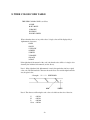
1
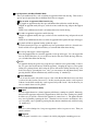
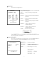
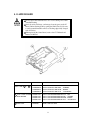
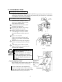
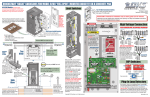
1ST PRINTING NOV 00
Standard Version
Owner’s Manual
SEGA ENTERPRISES, INC. USA
MANUAL NO. 4201-6609-01
Warranty
Your new Sega Product is covered for a period of 90 days from the date of shipment. This certifies
that the Printed Circuit Boards, Power Supplies and Monitor are to be free of defects in workmanship or materials under normal operating conditions. This also certifies that all Interactive Control
Assemblies are to be free from defects in workmanship and materials under normal operating conditions. No other product in this machine is hereby covered.
Sellers sole liability in the event a warranted part described above fails shall be, at its option, to
replace or repair the defective part during the warranty period. For Warranty claims, contact your
Sega Distributor.
Should the Seller determine, by inspection that the product was caused by Accident, Misuse, Neglect, Alteration, Improper Repair, Installation or Testing, the warranty offered will be null and void.
Under no circumstances is the Seller responsible for any loss of profits, loss of use, or other damages.
This shall be the exclusive written Warranty of the original purchaser expressed in lieu of all other
warranties expressed or implied. Under no circumstance shall it extend beyond the period of time
listed above.
BEFORE USING THE PRODUCT, BE SURE TO READ THE FOLLOWING:
To maintain the safety:
To ensure the safe usage of the product, be sure to read the following before using the product. The following
instructions are intended for the users, operators and the personnel in charge of the operation of the product.
After carefully reading and sufficiently understanding the warning displays and cautions, handle the product
appropriately. Be sure to keep this manual nearby the product or elsewhere convenient for referring to it
when necessary.
Herein, explanations which require special attention are enclosed with dual lines. Depending on the potentially hazardous degrees, the terms of WARNING, CAUTION, etc. are used. Be sure to understand the
contents of the displays before reading the text.
Indicates that mishandling the
product by disregarding this
warning will cause a potentially
hazardous situation which can
result in death or serious injury.
Indicates that mishandling the product
by disregarding this caution will cause
a slight hazardous situation which can
result in personal injury and or material
damage.
For the sage usage of the product, the following pictographs are used:
Indicates “HANDLE WITH CARE.” In order to protect the human body an equipment, this
display is attached to places where the Owner’s Manual and or Service Manual should be referred
to.
Perform work in accordance with the instructions herein stated.
Instructions for work are explained by paying attention to the aspect of accident prevention. Failing to
perform work as per the instructions can cause accidents. In the case where only those who have technical expertise should perform the work to avoid hazardous situation, the instructions herein state that the
serviceman should perform such work.
Be sure to turn off power before working on the machine.
To prevent electric shock, be sure to turn off power before starting the work in which the worker touches
the interior of the product. If the work is to be performed in the power-on status, the Instruction Manual
herein always states to that effect.
Be sure to ground the Earth Terminal (this, however, is not required in the case where a power cord
with earth is used).
This product is equipped with the Earth Terminal. When installing the product, Connect the Earth Terminal to the “accurately grounded indoor earth terminal” by using an earth wire. Unless the product is
grounded appropriately, the user can be subject to electric shock. After performing repair, etc. for the
Control equipment, ensure that the Earth Wire is firmly connected to the Control equipment.
Ensure that the Power Supply used is equipped with an Earth Leakage Breaker.
This product does not incorporate the Earth Leakage Breaker. Using a power supply which is not
equipped with the Earth Leakage Breaker can cause a fire when earth leakage occurs.
Be sure to use fuses which meet the specified rating. (only for the machines which use fuses).
Using fuses exceeding the specified rating can cause a fire and electric shock.
Specification changes (removal of equipment, conversion and addition) not designated by SEGA
are not allowed.
The parts of the product include warning labels for safety, covers for personal protection, etc. It is very
hazardous to operate the product by removing parts and or modifying the circuits. Should doors, lids
and protective parts be damaged or lost, refrain from operating the product, and contact where the
product was purchased from or the office herein stated. SEGA shall not be held responsible for any
accidents, compensation for damage to a third party, resulting from the specifications not designated by
SEGA.
Ensure that the product meets the requirements of appropriate Electrical Specifications.
Before installing the product, check for Electrical Specifications. SEGA products have a nameplate on
which Electrical Specifications are described. Ensure that the product is compatible with the power
supply voltage and frequency requirements of the location. Using any Electrical Specifications different
from the designated Specifications can cause a fire and electric shock.
Install and operate the product in places where appropriate lighting is available, allowing warning
labels to be clearly read.
To ensure safety for the customers, labels and printed instructions describing potentially hazardous
situation are applied to places where accidents can be caused. Ensure that where the product is operated
has sufficient lighting allowing the warnings to be read. If any label is peeled off, apply it again immediately. Please place an order with where the product was purchased from or the office herein stated.
When handling the Monitor, be very careful. (Applies only to the product w/monitor.)
Some of the monitor (TV) parts are subject to high tension voltage. Even after running off power, some
portions are still subject to high tension voltage sometimes. Monitor repair and replacement should be
performed only be those technical personnel who have knowledge of electricity and technical expertise.
Be sure to adjust the monitor (projector) properly. (Applies only to the product w/monitor.)
Do not operate the product leaving on-screen flickering or blurring as it is. Using the product with the
monitor not properly adjusted may cause dizziness or a headache to an operator, a player, or the customers.
When transporting or reselling this product, be sure to attach this manual to the product.
In the case where commercially available monitors and printers are used in this product, only the
contents relating to this product are explained herein. Some commercially available equipment has
functions and reactions not stated in this manual. Read this manual together with the specific Instruction Manual of such equipment.
• Descriptions herein contained may be subject to improvement changes without notice.
• The contents described herein are fully prepared with due care. However, should any question arise or
errors be found, please contact SEGA.
INSPECTIONS IMMEDIATELY AFTER TRANSPORTING THE PRODUCT TO THE LOCATION.
Normally, at the time of shipment, SEGA products are in a status allowing for usage immediately after
transporting to the location. Nevertheless, an irregular situation may occur during transportation. Before
turning on power, check the following points to ensure that the product has been transported in a satisfactory status.
Are there any dented portions or defects (cuts, etc.) on the external surfaces of the cabinet?
Are Casters and Adjusters, damaged?
Do the power supply voltage and frequency requirements meet with those of the location?
Are all wiring connectors correctly and securely connected? Unless connected in the correct direction,
connector connections can not be made accurately. Do not insert connectors forcibly.
Do power cords have cuts and dents?
Do the fuses used meet specified rating? Is the Circuit Protector in an energized status?
Are all accessories available?
Can all Doors and Lids be opened with the Accessory keys? Can Doors and Lids be firmly closed?
TABLE OF CONTENTS
BEFORE USING THE PRODUCT, BE SURE TO READ THE FOLLOWING:
1. HANDLING PRECAUTIONS ............................................................... 2
2. HOW TO PLAY ...................................................................................... 3 - 6
3. TEST MODE .......................................................................................... 7 - 10
A. SYSTEM MENU
B. GAME TEST MODE
1 INPUT TEST
Switch input test is performed.
2 GAME ASSIGNMENTS
Various settings such as game difficulty, etc. can be set.
3 BOOKKEEPING
Allows for checking data such as the number of coins inserted, operation time, game
time, etc.
4 BACKUP DATA CLEAR
Clears the contents of BOOKKEEPING.
4. GAME BOARD ...................................................................................... 11
5. COIN SELECTOR .................................................................................. 12 - 13
6. DESIGN RELATED PARTS ................................................................... 14 - 15
7. PARTS LIST ............................................................................................ 16 - 19
8. WIRE COLOR CODE TABLE ............................................................... 20
9. WIRING DIAGRAM .............................................................................. 21 - 22
Use of this product is unlikely to cause physical injuries or damages to property. However,
where special attention is required this is indicated by a thick line, the word “IMPORTANT”
and its sign in this manual.
Indicates that mishandling the product by disregarding this display can cause the
product’s intrinsic performance not to be obtained, resulting in malfunctioning.
If this is used on the cabinet such as BLAST CITY, MEGALO 410,
etc., whose coin chute is used in common with Player 1 and Player 2,
be sure to change the setting of COIN CHUTE TYPE from
INDIVIDUAL to COMMON in the COIN ASSIGNMENTS. If the
game is played on such cabinets with the COIN CHUTE TYPE set to
INDIVIDUAL, the game can not be played at Player 2 side. As for
COIN ASSIGNMENTS, refer to NAOMI SERVICE MANUAL.
When power is turned on for the first time, be sure to enter into the
TEST MODE to check in the INPUT TEST if INPUT device is
satisfactory.
1
1. HANDLING PRECAUTIONS
To prevent electric shock or IC Board malfunctioning, be sure to turn off the
power for the cabinet when installing or removing the IC Board.
Extraneous matter such as dust on the IC Board can cause the IC Board to generate
heat and result in a fire due to short circuit, etc. Ensure the IC Board surfaces are
always kept clean.
Use NAOMI for the cabinets compatible with JVS. Using NAOMI for the cabinet
other than those compatible with JVS can cause generation of heat and a fire.
Be sure to connect the IC Board and connectors completely. Insufficient insertion
can damage IC Board, etc.
For the IC Board circuit inspection, only the use of Logic Tester is permitted.
The use of ordinary testers is not permitted as these can damage the IC Board.
Do not subject the IC Board to static electricity when installing the IC Board in
the cabinet or when connecting wire harness connectors to the IC Board.
When soldering buttons, etc. to the wire harnesses, be sure to remove the wire
harnesses from the IC Board so as not to subject the IC Board to heat.
Using NAOMI without the Shield Case can cause electric wave trouble. Be sure
to use NAOMI together with the accessory Shield Case.
The monitor frequency corresponding to NAOMI is 15 kHz or 31 kHz. NAOMI
can not be used for the cabinet incorporating a monitor or projector not
corresponding to 15 kHz or 31 kHz.
Concerning the display of JAMMA VIDEO STANDARD:
JAMMA VIDEO STANDARD adopted by NAOMI is referred to as JVS. As against this
Standard, the conventional JAMMA STANDARD which employs 56P Edge Connectors adopted
by ST-V, etc. is displayed as Old JAMMA STANDARD.
The specific Manual attached to each game sometimes displays JVS as JV STANDARD, New
JAMMA STANDARD, or JAMMA 2 STANDARD AGAINST OLD JAMMA STANDARD as
JAMMA STANDARD, JS, etc.
The contents herein described are subject to change without notice.
2
2. HOW TO PLAY
ON-SCREEN DISPLAY
Monitor Position
HORIZONTAL
Synchronous Frequency
15/31 kHz
CONTROL PANEL
Moving of Wrestlers
Attack Button
A
Grapple Button Support Button
G
S
Attack Button
Enables a wrestler to punch and kick an opponent.
Grapple Button
Enables a wrestler to grapple an opponent. Also enables a wrestler to
throw, or swing onto the ropes, an opponent after grappling.
Support Button
Enables a wrestler to take an action other than attacking and grappling;
that is, to run, mount to a corner, guard, and block.
Available Playing Modes
Two playing modes are available.
Exhibition Mode
This enables you to play a 10-game tournament. You choose a wrestler as yourself and a partner
wrestler, and specify the attacks allowed for the partner; thus you may use your own vital techniques as
well as the various partner attacks in the game. Additional wrestler (from the CPU) may unexpectedly
burst into the ring or you may happen to move to a variety of stages; thus several game effects are
prepared.
Maximum 4 wrestlers can play simultaneously. In this case all the wrestlers other than yourself (as a
wrestler) may be opponents; you may attack one of them together with the rest of them; or any one of
the supporting wrestlers may suddenly betray you. Thus you can enjoy a heated and thrilling game.
Royal Ramble Mode
This enables you to join in a battle royal of maximum 9 persons on the ring. Maximum 4 wrestlers can
play. Any wrestlers fallen from the ring is disqualified. The bottom center part of the monitor screen
shows the number of persons to clear; new wrestlers will continue to appear on the ring until the
number becomes 0 (zero). The number counts down only if the playing wrestlers make the CPU
wrestler fallen from the ring. Winning wrestlers are those who still remain on the ring when the number
is 0 (zero). Furthermore, the high-level S wrestlers may burst into the ring when the number of persons
to clear approaches to 0 (zero).
3
Basic Operations
Attack Button
This button enables you to punch and kick an opponent. Press the button repeatedly to attack
without a break.
Grapple Button
This button enables you to grapple an opponent and then make him staggered or groggy,
throw him or swing him onto the ropes. The button also enables you to throw down or squeeze
a downed opponent. Furthermore, the button enables you to pick up a weapon on the stage
other than the ring.
Support Button
This button enables you to run into the directions set by the lever; and then you may use the
attack and/or grapple buttons to battle. If you are nearby the corner, you may set the lever into
the direction of the post, press the button to mount to the corner, and use the attack and/or
grapple button to battle. Also, you may hold down the button to guard yourself against an
opponent’s offences. In addition, you may press the button in a timely manner against an
opponent’s offence thereby to counterattack. Finally the button enables you to pinfall a downed
opponent.
Button Operations after Grappling
Pressing the Attack Button after Grappling
This action enables you to make an opponent groggy (defenseless). This action, if taken
while setting the lever into any desired direction, enables you to make an opponent staggered
(also, defenseless) into the set direction. Press the attack button again to punch or kick the
groggy or staggered opponent while the grapple button to throw. In these cases, the oppornent
cannot counterattack.
Pressing the Grapple Button after Grappling
This action, if taken while setting the lever into any of the neutral/upper/lower/left/right
directions, enables you to throw a grappled opponent even if grappled in the rear.
Pressing the Support Button after Grappling
This action enables you to swing or hammer-throw an opponent onto the ropes. After swinging,
press the attack or grapple button to battle. Alternately set the lever into any desired directions
to swing the opponent into the set direction. Set it into a slant direction to swing the opponent
to the corner in the set direction and thus make the opponent corner-down. Grapple, and then
punch, kick, or throw the corner-downed opponent.
NOTE: When grappled you can counterattack by pressing the button same as the one opponent
is pressing.
4
Partner Attacks (in Exhibition Mode)
According to a WWF rule, you specify your own wrestler and its partner. Attacks by the
partner are called partner attacks. You also specify any one out of the three partner attacks;
Type A, Type B, and Type C. You can use a partner attack by pressing any two buttons
simultaneously.
Independent Partner Attacks
Only a partner wrestler attacks an opponent. These attacks include a dashing punch/kick,
continuous attack, weapon attack, dived attack from a corner, and vital technique.
Two-Platoon Attacks
You (as a wrestler) may try to grapple (or punch or kick) an opponent. After successfully
grappling, you and the partner cooperate to do the two-platoon attacks.
Supporting Partner Attacks
The partner does not attack but provides various supporting actions. Such actions include
giving of a weapon, increasing of your special gauge number, decreasing of an opponent’s
special gauge number, making an opponent groggy, escaping from a pitfall, etc.
NOTE: The Partner Attack are not usable in a wire-netting stage.
“S” Special Gauge Icon
Special gauge icon is located below a power gauge icon and indicates a “S” number. Saving
and increasing of the “S” number enables you to use high-grade (HG) attacks, vital techniques,
etc. You can use these features by pressing the three buttons simultaneously.
HG Attacks (decreasing of “S” number: 1 each)
HG attack is more powerful than a usual one. Such powerful attacks include a dashing attack,
attack from a corner, downward attack, etc. and thus are usable in various situations.
Vital Technique (decreasing of “S” number: 3 each)
Every wrestler is given one vital technique (and two lock techniques). Applicable situation
of these techniques varies from wrestler to wrestler. One technique is only applicable in a
standing position, another for a downed opponent, and the other from a corner. Each vital
technique can seriously damage an opponent and even KO a powerless opponent.
Escaping from a Pinch (decreasing of “S” number: 1 each)
You can escape from a pinch such as a pinfall, groggy state, downed state, grappled state, etc.
5
Special Operations with Royal Ramble Mode
The royal ramble mode has a rule of making an opponent fallen from the ring. This needs to
specify special operations that an exhibition mode does not support.
How to make an opponent fallen from the ring
To grapple an opponent nearby the ropes and hammer-throw him into outside the ring:
Grapple an opponent nearby the ropes, set the lever into outside the ring, and press the support
button.
NOTE: In an exhibition mode this is to hammer-throw into inside the ring.
To make an opponent stagger into outside the ring:
Grapple an opponent nearby the ropes, set the lever into outside the ring, and press the attack
button.
NOTE: In an exhibition mode this is to make an opponent bound against the ropes and stagger.
To punch or kick an opponent leaning against the ropes:
If attacked nearby the ropes, an opponent may lean against them and be in a downed state.
Punch or kick such an opponent and then you can make him fallen from the ring.
To raise up and stagger a downed opponent:
Press the grapple button for a downed opponent to raise up and stagger. You can stagger him
into any desired directions; if you set the lever into the direction outside the ring, therefore,
you can make him fallen from the ring.
NOTE:
An opponent having the power may grasp the ropes and thus resist against falling. If this is
the case, press the attack button to stonk the opponent. Grasping the ropes to resist against
falling for a prolonged time and loosing the power will result in falling from the ring. Get
back to the ring by operating the lever. Also, you can return to the ring immediately when
pressing the three buttons simultaneously with decreasing “S” number by 1.
Referee Knockout
You can attack a referee only with a weapon. State of the Referee Knocked Out occurs when
you have knocked out the referee twice. In this state the partner attacks can be repeated
without a break while usually they can be repeated only with a break. Also in this state you
are not counted down even in a pinfall.
Win and Loss Rule (in Exhibition Mode)
Pinfall
Press the support button for a downed opponent, which starts counting for a pinfall. Alternately,
throw down an opponent and press the support button, which also starts counting for a pinfall.
In either case you will be a winner if the opponent is counted out to 3. The pinned wrestler
may cancel a pinfall by operating the lever. (Turn the lever for an easier cancellation.) Also,
you can quickly cancel a pinfall by pressing the three buttons simultaneously with decreasing
“S” number by 1.
KO
Exercise a vital technique for a low-power opponent to reduce its power to zero. Then you
will be a winner.
Judgment
When the game is ended in a tie, a winner is decided by judging the remaining power etc.
6
3. TEST MODE
A. SYSTEM MENU
When you have changed the settings of the SYSTEM ASSIGNMENTS, COIN
ASSIGNMENTS, and GAME ASSIGNMENTS (on the GAME TEST
MODE screen), be sure to select the EXIT from the SYSTEM MENU screen
and press the test button to exit from a test mode. This action can store the
new settings in the IC on the board. Disconnecting the power when in a test
mode may fail to store the new settings and eventually the present settings
may remain effective.
This game allows you to set the number of players to 2 or 4. Correctly set it
according to the number of the input cables connected to the cabinet. Failure
to do so may malfunction the game.
This test mode mainly allows the IC Board to be checked for accurate functioning, monitor
color to be adjusted as well as COIN ASSIGNMENTS and GAME ASSIGNMENTS to be
adjusted.
1) After turning power on, press the TEST Button to have the following SYSTEM MENU
displayed.
SYSTEM MENU
RAM TEST
JVS TEST
SOUND TEST
C.R.T. TEST
SYSTEM ASSIGNMENTS
COIN ASSIGNMENTS
BOOKKEEPING
BACKUP DATA CLEAR
CLOCK SETTING
ROM BOARD TEST
GAME TEST MODE
[XXXXXXX
]
-> EXIT
SELECT WITH SERVICE BUTTON
AND
PRESS TEST BUTTON
In the SYSTEM ASSIGNMENTS.
CABINET TYPE is set to 2 PLAYER(S) or 4 PLAYER(S),
and MONITOR TYPE is set to HORIZONTAL.
The other items are initially set to as follows:
ADVERTISE SOUND ON
SERVICE TYPE
COMMON
COIN ASSIGNMENTS initial settings as follows:
COIN CHUTE TYPE: COMMON
COIN/CREDIT SETTING: #1
COIN CHUTE #1 (#2): 1 COIN 1 CREDIT
SEQUENCE SETTING of COIN ASSIGNMENTS functions as follows:
SEQUENCE 1: Number of credits required for game start
(initial value = 1 CREDIT).
SEQUENCE 2: Number of credits required for CONTINUE
(initial value = 1 CREDIT).
SEQUENCE 3~8: NOT USED.
MEANING OF DISPLAY IN BOOKKEEPING 2/2
P1 (~P4) SEQ 1: Play frequency of Player 1
(~Player 4).
P1 (~P4) SEQ 2: Frequency CONTINUE by Player 1
(~Player 4).
P1 (~P4) SEQ 3~8: NO USE.
CAUTION FOR SETTING
When you have set the SERVICE TYPE and the COIN CHUTE TYPE to INDIVIDUAL,
the players 1 and 2 share the credit of COIN 1 and SERVICE 1 while the players 3 and 4
share the credit of COIN 3 and SERVICE 3.
If you want to use the coin chute for COIN 2 (4) and the service button for SERVICE 2 (4),
therefore, set the SERVICE TYPE and the COIN CHUTE TYPE to COMMON.
7
2) Press the SERVICE Button to move the arrow. Bring the arrow to the desired item and
press the TEST Button.
3) Press the TEST Button in the GAME TEST MDOE to display the GAME TEST MODE
peculiar to this game. See the next page onward.
4) Upon finishing the test, bring the arrow to EXIT and press the TEST Button to return
to the Game mode.
For detailed explanations as regards the SYSTEM TEST MODE, refer to NAOMI
SERVICE MANUAL (420-6455-01).
B. GAME TEST MODE
Move the -> mark to GAME TEST MODE item on the SYSTEM MENU screen, and
press the TEST Button. The game-specific GAME TEST MODE screen appears.
<<GAME TEST MODE>>
1
2
3
4
INPUT TEST
GAME ASSIGNMENTS
BOOKKEEPING
BACKUP DATA CLEAR
-> EXIT
SELECT WITH SERVICE BUTTON
AND
PRESS TEST BUTTON
GAME TEST MODE screen
Pressing the SERVICE Button can move the -> mark. Move the -> mark to a desired
item, and press the TEST Button.
After testing, select the EXIT and press the TEST Button. The SYSTEM MENU screen
reappears.
8
1 INPUT TEST
This screen tests the input devices.
Press each button and make sure that the corresponding OFF
disappears and the ON appears.
<<INPUT TEST>>
TEST BUTTON
[OFF]
SERVICE BUTTON [OFF]
1P
[OFF]
[OFF]
[OFF]
[OFF]
[0][0][0]
[0] [0]
[0][0][0]
START
ATTACK
GRAPPLE
SUPPORT
STICK
2P
[OFF]
[OFF]
[OFF]
[OFF]
[0][0][0]
[0] [0]
[0][0][0]
PRESS SERVICE BUTTON
AND
TEST BUTTON TO EXIT
TEST ............... Changes to ON when pressing the TEST
BUTTON.
SERVICE ........ Changes to ON when pressing the SERVICE
BUTTON.
START ............ Changes to ON when pressing the START
BUTTON.
ATTACK ......... Changes to ON when pressing the ATTACK
BUTTON.
GRAPPLE ..... Changes to ON when pressing the
GRAPPLE BUTTON.
SUPPORT ..... Changes to ON when presssing the
SUPPORT BUTTON.
LEVER ........... From 0 to1 on the set direction.
000
0 0
000
If set to the upper
right direction.
001
0 0
000
If the CABINET TYPE is set to 4 PLAYER(S) on the SYSTEM ASSIGNMENTS screen,
the 3P and 4P columns, are displayed.
2 GAME ASSIGNMENTS
This screen sets the difficulty level and playing time. Press the SERVICE Button to
move to a desired item, and press the TEST Button to select a new setting.
DIFFICULTY ......... 5 levels are selectable.
<< GAME ASSIGNMENTS >>
DIFFICULTY
TIME LIMIT
RESET
[NORMAL]
[180]
EXIT
TIME LIMIT .......... Playing time in minute for a game.
60, 120, or 180 is selectable.
RESET .................... Initial settings are recovered.
Initial settings are:
SELECT WITH SERVICE BUTTON
AND
PRESS TEST BUTTON
DIFFICULTY ...... NORMAL
TIME LIMIT ...... 180
9
3 BOOKKEEPING
This screen displays the playing time data.
<< BOOKKEEPING >> PAGE 1/2
PLAY TIME
AVERAGE TIME
LONGEST TIME
SHORTEST TIME
-D-H-M-S
-M-S
-M-S
-M-S
PLAY TIME ................. Actual playing time data (For 2P
game, playing time periods are not
overlapped.)
Press the TEST Button to open the next PAGE 2/2
screen.
PRESS TEST BUTTON TO CONTINUE
<< BOOKKEEPING >> PAGE 2/2
0M00S ~ 0M29S
0M30S ~ 0M59S
1M00S ~ 1M29S
1M30S ~ 1M59S
2M00S ~ 2M29S
2M30S ~ 2M59S
3M00S ~ 3M29S
3M30S ~ 3M59S
4M00S ~ 4M29S
4M30S ~ 4M59S
5M00S ~ 5M29S
5M30S ~ 5M59S
6M00S ~ 6M29S
6M30S ~ 6M59S
7M00S ~ 7M29S
7M30S ~ 7M59S
8M00S ~ 8M29S
8M30S ~ 8M59S
9M00S ~ 9M29S
9M30S ~ 9M59S
OVER 10M00S
-
This screen indicates the by-playtime play frequency.
Press the TEST Button to return to the GAME TEST MODE
screen.
PRESS TEST BUTTON TO EXIT
4 BACKUP DATA CLEAR
This screen clears the high scores and the bookkeeping data.
<< BACKUP DATA CLEAR >>
YES (CLEAR)
-> NO (CANCEL)
SELECT WITH SERVICE BUTTON
AND PRESS TEST BUTTON
Press the SERVICE Button to move the -> mark to YES
item, and press the TEST Button. When the system
completes clearing, the COMPLETED message appears on
the screen. Press the TEST Button to return to the GAME
TEST MODE screen. Press the SERVICE Button to move
the -> mark to NO item, and press the TEST Button. The
system does not execute clearing, but returns to the GAME
TEST MODE screen.
10
4. GAME BOARD
Do not expose the Game Board so as to avoid causing an accident
or malfunctioning.
Static electricity discharge can damage electronic parts on the IC
Board. Before starting work by opeing the Shield Case Lid, be sure
to touch grounded metallic surfaces to discharge physically charged
static electricity.
When replacing the Game Board, refer to the CVT Manual and
Instruction Manual.
ASSY CASE ( 1
+ 2 )
PART NO.
DESCRIPTION
840-0040D-01
840-0040D-02
840-0040D-03
840-0040D-04
ASSY CASE NAO WR1 USA
ASSY CASE NAO WR1 EXP
ASSY CASE NAO WR1 KOR
ASSY CASE NAO WR1 AUS
1 ASSY CASE NAOMI 840-0001A-01
MAIN BOARD
2 ROM CASE
: USA
: OTHERS
: KOREA
: AUSTRALIA
840-0001A-02
840-0001A-03
840-0001A-04
ASSY CASE NAOMI MAIN BD USA
ASSY CASE NAOMI MAIN BD EXP
ASSY CASE NAOMI MAIN BD KOR
ASSY CASE NAOMI MAIN BD AUS
840-0040C
ROM CASE NAO WR1
11
:USA
: OTHERS
: KOREA
: AUSTRALIA
5. COIN SELECTOR
HANDLING THE COIN JAM
If the coin is not rejected when the REJECT BUTTON is pressed, open the coin chute door
and open the selector gate. After removing the jammed coin, put a normal coin in and check
to see that the selector correctly functions.
CLEANING THE COIN SELECTOR
1
2
3
4
5
6
GATE
The coin selector should be cleaned
once every 3 months. When cleaning,
follow the procedure below:
Turn the power for the machine OFF.
Open the coin chute door.
Open the gate and dust off by using a
soft brush (made of wool, etc.).
Remove and cleen smears by using a
soft cloth dipped in water or diluted
chemical detergent and then squeezed
dry.
Remove the CRADLE.
When removing the retaining ring(Ering), be very careful so as not to bend
the shaft.
Remove stain from the shaft and pillow
portions by wiping off with a soft cloth,
etc.
After wiping as per #5 above, further
apply a dry cloth, etc. to cause the coin
selector to dry completely.
FIG. 5a
CRADLE
FIG.5b
Never apply machine oil, etc. to
the coin selector
After cleaning the Coin Selector,
Insert a regular coin during the
normal working status and ensure
that the Selector functions correctly.
Insert a coin
while keeping
COIN INSERTION TEST
the Reject
Once a month, when performing the COIN SW Button pressed
down and check
TEST, simultaneously check the following:
if it is
rejected.
Does the Coin Meter count satisfactorily?
Does the coin drop into the Cashbox correctly?
Is the coin rejected when inserted while keeping
the REJECT BUTTON is pressed down?
COIN METER
FIG. 5c
12
OPTIONAL DOLLAR BILL ACCEPTOR
THE COIN DOOR ASSEMBLY USED ON WWF ROYAL RUMBLE MINI
DX COMES EQUIPPED TO ACCEPT A DOLLAR BILL ACCEPTOR. ALL
NEEDED WIRING CONNECTIONS ARE CONVIENENTLY LOCATED INSIDE
THE GAME FOR THIS APPLICATION.
THE COIN DOOR CAN ACCCOMMODATE THE FOLLOWING
VALIDATOR(S):
FORWARD-MOST
HOLE POSITION
**42-1155-00
Mars 2000 series
MARS VALIDATOR $1, 2, 5 300 CAP
The frame and cashbox enclosure on this coindoor has been modified to accomodate
a Mars 2000 series upstacker. A 2000 series stacker can be added by simply removing the cut-out plate. This one entry door can be ordered through Happ Controls or
one of Happ Controls authorized distributors. The part number is 40-6000-10EX.
The Mars stacker can be obtained through an autherized Mars distibutor.
Note: Your game may have either Happ Controls Coin Door Assembly or the Wells
Gardner Coin Door Assembly (not shown).
**Happ part number
NOTE: Your game is equipped with a Wells Gardner coin door assembly Model #WGD802105-2608.
Security Locking Bar/Bracket Set Part No.# 999-1102
13
6. DESIGN RELATED PARTS
(D-1/2)
1
6
2
4
3
5
7
7
8
8
9
10
14
6. DESIGN RELATED PARTS
(D-2/2)
ITEM NO.
PART NO.
DESCRIPTION
1
2
3
999-1094
999-1113
999-1098
4
5
6
7
999-1090
999-1091
999-1115
999-1101
MARQUEE PLATE BILLBOARD
MARQUEE END CAP DECAL LEFT
INSTR #2 PLAYER INSTR. - SELECT WRESTLER BELOW BILLBOARD
DECAL BEZEL LEFT (2 PER)
DECAL BEZEL RIGHT (2 PER)
MARQUEE END CAP DECAL RIGHT
INSTR. #1 MAIN - MOVEMENT INS. (2 PER) BOTTOM OF EACH MONITOR BEZEL
CONTROL PANEL ART
DECAL FRONT DOOR LEFT
DECAL FRONT DOOR RIGHT
DECAL SIDE CABINET UPPER RS
DECAL SIDE CABINET UPPER LS
8
9
10
NOT SHOWN
NOT SHOWN
999-1095
999-1096
999-1097
999-1100
999-1099
15
7. PARTS LIST
1 TOP ASSY
(D-1/2)
13
10
12
1
2
8
3
7
4
6
5
9
11
16
1 TOP ASSY
ITEM NO.
1
2
3
4
5
6
7
8
9
10
11
12
13
NOT SHOWN
NOT SHOWN
NOT SHOWN
(D-2/2)
PART NO.
999-1088
999-1109
999-1089
999-1110
999-1086
999-1111
999-1087
999-1112
999-1095
999-1092
999-1116
999-1114
LOC. PURCHASE
999-1093
999-0167
999-0169
DESCRIPTION
PUSHBUTTON ROUND RED 53-9200-13 (4 PER)
JOYSTICK HAPP RED #50-7608-10
PUSHBUTTON ROUND BLUE 53-9200-12 (4 PER)
JOYSTICK HAPP BLUE #50-7608-12
PUSHBUTTON ROUND GRN. 53-9200-13 (4 PER)
JOYSTICK HAPP GRN. #50-7608-13
PUSHBUTTON ROUND YEL. 53-9200-15 (4 PER)
JOYSTICK HAPP YEL. #50-7608-15
OVERLAY - CONTROL PANEL
MONITOR BEZEL GOLD (2 PER)
HANDLE PIPE CHROME
MARQUEE BEZEL GOLD
36” 30 WATT FLUORESCENT FIXTURE
CONTROL PNL & HINGE - SILVER
LEG LEVELER 1/2 - 13 X 4”
CASTER 160 - 2 1/2
NOTE: Your game will come equipped with a Wells Gardner 29” monitor Model #WGM2972-U0T-529K.
17
2 SW UNIT
4
2
1
3
ITEM NO.
PART NO.
DESCRIPTION
1
2
3
4
509-5028
220-5179
601-0042
999-1050
SW PB 1M
POT 5K OHM 31VA305
KNOB 22MM
COIN METER
3 AC UNIT
1
2
ITEM NO.
PART NO.
DESCRIPTION
1
2
999-1044
999-0676
AC INLET PANEL TYPE
SW ROCKER J8 V-B
18
4 ASSY POWER SUPPLY
1
2
3
4
ITEM NO.
PART NO.
1
2
3
4
400-5397-01
999-0141
838-13616
837-13551-92
DESCRIPTION
POWER SUPPLY
TRANSFORMER MCI-4-49-703
AUDIO POWER AMP 2CH
I/O CONTROL BOARD FOR JVS
19
8. WIRE COLOR CODE TABLE
THE WIRE COLOR CODE is as follow:
A PINK
B SKY BLUE
C BROWN
D PURPLE
E LIGHT GREEN
Wires other than those of any of the above 5 single colors will be displayed by 2
alphanumeric characters.
1 RED
2 BLUE
3 YELLOW
4 GREEN
5 WHITE
7 ORANGE
8 BLACK
9 GRAY
If the right-hand side numeral of the code is 0, then the wire will be of a single color
shown by the left-hand side numeral (see the above).
Note 1: If the right-hand side alphanumeric is not 0, that particular wire has a spiral
color code. The left-hand side character shows the base color and the right-hand side
one, the spiral color.
<Example> 51 ****** WHITE/RED
RED
WHITE
Note 2: The character following the wire color code indicates the size of the wire.
U:
K:
L:
None:
AWG16
AWG18
AWG20
AWG22
20
VISIT OUR WEBSITE!