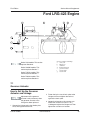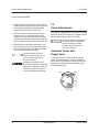
1
Technical
Publications
®
Supplement
Service
Manual
For the following products:
S-40
Z-45/22
S-80 & 85
Z-60/34
First Edition, Third Printing
Part No. 35023
First Edition
Genie Industries has endeavored to deliver the
highest degree of accuracy possible. However,
continuous improvement of our products is a
Genie policy. Therefore product specifications are
subject to change without notice.
Readers are encouraged to notify Genie of errors
and send in suggestions for improvement. All
communications will be carefully considered for
future printings of this and other manuals. Please
write or fax to the Technical Publications team:
Genie North America
Telephone (206) 881-1800
Toll Free in U.S.A. 800 536-1800
Toll Free in Canada 800 426-8089
Fax (206) 883-3475
Genie Europe
Telephone (44) 01636-605030
Fax (44) 01636-611090
Genie Industries
PO Box 69
Redmond, WA 98073-6900, USA
Fax Number: (206) 556-8528.
If you have any questions, call Genie Industries.
®
Copyright © 1995 by Genie Industries
First Edition:
First Printing, February 1995
Second Printing, March 1995
Third Printing, June 1995
Genie® is a registered trademark
of Genie Industries. Registered 2009987
Patents pending
Printed on recycled paper
Printed in U.S.A.
ii
Genie Supplement
Part No. 35023
First Edition
How To Use This Supplement
Serial Number Breaks:
This supplement is an addition to the service
manuals listed below. The serial numbers listed
below mark the first affected machine . Only the
following changes are documented in this
supplement:
Product
S-40
S-80 & S-85
Z-45/22
Z-60/34
Machines after
271
132
2134
481
Replacement of the Ford LSG-423 engine
with the Ford LRG-423 engine
If you have any questions about what this
supplements covers or how it fits in to your
existing documentation, please call the Genie
Industries Service Department.
Service Manual
There are four sections to the service manual
supplement.
The Specifications section contains only the
specifications for Ford LRG-423 Engine.
The maintenance section contains only those
maintenance procedures that are different for the
Ford LRG engine. Please note the procedure
number for your machine, indentified at the
beginning of each procedure in this supplement.
The schematic section contains complete, updated
electrical schematics for the Gasoline/LPG
machines. The schematics are arranged by
product.
The repair section contains the complete Ford
LRG engine section. Please note the section
number for your machine.
Service Manuals:
Product
S-40
S-80 & S-85
Z-45/22
Z-60/34
Part No. 35023
Part Number
32222
34032
32960
30105
Genie Supplement
iii
First Edition
Table of Contents
Section One
Specifications
Ford LRG-423 Engine ................................................................................................................................ 1
Section Two
Scheduled Maintenance Procedures
B-1
Check the Engine Belt(s) ............................................................................................... 2
B-2
Check and Adjust the Engine Idle Mixture - Gasoline/LPG Models ............................... 2
B-3
Check and Adjust the Engine RPM ............................................................................... 2
C-1
Replace the Gasoline Fuel Filter - Gasoline/LPG Models ............................................. 4
C-2
Replace the PCV Valve - Gasoline/LPG Models ........................................................... 5
C-3
Replace the Spark Plugs - Gasoline/LPG Models ......................................................... 6
C-4
Check and Adjust the Air/LPG Mixture - Gasoline/LPG Models .................................... 6
C-5
Check and Adjust the Ignition Timing - Gasoline/LPG Models ...................................... 8
D-1
Change or Recondition the Engine Coolant - Gasoline/LPG Models ............................. 8
D-2
Change the Fuel Lines .................................................................................................. 9
D-3
Check the Engine Valve Clearance - Gasoline/LPG Models ....................................... 10
D-4
Check the Engine Cylinder Compression - Gasoline/LPG Models .............................. 10
D-5
Clean the PCV Hoses and Fittings - Gasoline/LPG Models ........................................ 11
D-6
Replace the Timing Belt - Gasoline/LPG Models ........................................................ 12
Section Three
S-40 Electrical Schematics
Electrical Schematic - Gasoline/LPG Models .............................................................. 13
Ground Control Box Legend - Gasoline/LPG Models .................................................. 15
Relay Panel Legend - Gasoline/LPG Models .............................................................. 16
Platform Control Box Legend - Gasoline/LPG Models ................................................ 17
S-80/85 Electrical Schematics
Electrical Schematic - Gasoline/LPG Models .............................................................. 18
Ground Control Box Legend - Gasoline/LPG Models .................................................. 20
Relay Panel Legend - Gasoline/LPG Models .............................................................. 21
Platform Control Box Legend - Gasoline/LPG Models ................................................ 22
Z-45/22 Electrical Schematics
Electrical Schematic - Gasoline/LPG Models .............................................................. 23
Ground Control Box Legend - Gasoline/LPG Models .................................................. 25
Relay Panel Legend - Gasoline/LPG Models .............................................................. 26
Platform Control Box Legend - Gasoline/LPG Models ................................................ 27
iv
Genie Supplement
Part No. 35023
First Edition
Section Three, continued
Z-60/34 Electrical Schematics
Electrical Schematic - Gasoline/LPG Models .............................................................. 28
Ground Control Box Legend - Gasoline/LPG Models .................................................. 30
Relay Panel Legend - Gasoline/LPG Models .............................................................. 31
Platform Control Box Legend - Gasoline/LPG Models ................................................ 32
Section Four
Part No. 35023
Repair Procedures
7-1 Governor Actuator ............................................................................................. 33
7-2
Choke Adjustments ............................................................................................ 34
7-3
Timing Adjustment ............................................................................................. 35
7-4
Carburetor Adjustment ....................................................................................... 35
7-5
RPM Adjustment ................................................................................................ 35
7-6
Flex Plate ........................................................................................................... 35
7-7
Water Temperature and Oil Pressure Gauges ................................................... 36
7-8
Vacuum Switch .................................................................................................. 36
Genie Supplement
v
First Edition
Genie Supplement
Part No. 35023
First Edition
Service Manual Supplement
Specifications
Ford Engine LRG-423
Displacement
140 cu in
2.3 liters
Number of cylinders
Bore & stroke
4
3.781 x 3.126 inches
96.04 x 79.4 mm
Horsepower
63 @ 4000 rpm
Firing order
1-3-4-2
S-40 RPM Specifications
Low idle - carburetor
900 rpm
Oil viscosity requirements
Temperature below 60°F / 15.5°C
-10°F to 90°F / -23°C to 32°C
10W-40 to 10W-50
Temperature above
20°F / -6.6°C
20W-40 or 20W-50
Use oils meeting API classification SG (labeled SG/CC
or SG/CD) as they offer improved wear protection.
Units ship with 10W-40 SG/CC.
1600 rpm
Starter motor
High idle
2500 rpm
Normal engine cranking speed
Low idle - carburetor
900 rpm
10W-30
Temperature above
-10°F / -23°C
Low idle - electronic governor
S-80/85 RPM Specifications
5W-30
200 to 250 rpm
Current draw, normal load
170A
Current draw, maximum load
200A
Low idle - electronic governor
1600 rpm
Current draw, minimum
140A
High idle
2500 rpm
Maximum circuit voltage drop
while starting (normal temperature)
0.5V DC
Brush length, new
0.66 in
16.8 mm
Brush length wear limit
0.25 in
6.35 mm
Z-45/22 RPM Specifications
Low idle - carburetor
900 rpm
Low idle - electronic governor
1400 rpm
High idle
2150 rpm
Z-60/34 RPM Specifications
Brush spring tension
Low idle - carburetor
900 rpm
Low idle - electronic governor
1600 rpm
High idle
2500 rpm
Governor
electronic
Compression ratio
9.4:1
Compression pressure (approx.)
Pressure (psi) of lowest cylinder must be
at least 75% of highest cylinder
Valve clearances collapsed tappet
Oil capacity
(including filter)
Part No. 35023
Bolt torque
through brush
45 to 84 inch-pounds
5.08 to 9.5 Nm
Brush mounting
bolt torque
15 to 20 foot-pounds
20 to 27 Nm
Maximum commutator
run-out
0.005 inches
0.127 mm
Battery
Type
0.035 to 0.055 inches
0.889 to 1.397 mm
Quantity
Cold cranking ampere
Lubrication system
Oil pressure
(operating temp. @ 2000 rpm)
64 ounces
18 Newtons
40 to 60 psi
2.75 to 4.1 bar
5 quarts
4.7 liters
Reserve capacity @ 25A rate
12V, Group 31
1
1000A
200 minutes
Fuel pump
Electronic solenoid
Genie Industries
7 psi
0.48 bar
1
Service Manual Supplement
First Edition
Scheduled Maintenance Procedures
B-1
Check the Engine Belt(s)
B-2
Check and Adjust the Engine Idle
Mixture - Gasoline/LPG Models
Genie S-40 models: This
procedure replaces B-1.
Genie S-40 models: This
procedure replaces B-11.
Genie S-80/85 models: This
procedure replaces B-1.
Genie S-80/85 models: This
procedure replaces B-11.
Genie Z-45/22 models: This
procedure replaces B-1.
Genie Z-45/22 models: This
procedure replaces B-11.
Genie Z-60/34 models: This
procedure replaces B-1.
Maintaining the engine belt(s) is essential to good
engine performance and service life. The machine
will not operate properly with a loose or defective
belt and continued use may cause component
damage.
Do not inspect while the engine
is running. Remove the key to
secure from operation.
Beware of hot engine
components. Contact with hot
engine components may cause
severe burns.
Genie Z-60/34 models: This
procedure replaces B-11.
Complete information to perform this procedure is
available in the Ford LRG-423 2.3 Liter Industrial
Engine Service Manual (Ford number: PPD-194287). Genie part number 33907.
B-3
Check and Adjust the
Engine RPM
Genie S-40 models: This
procedure replaces B-12.
1 Inspect the engine belt for:
· cracking
Genie S-80/85 models: This
procedure replaces B-12.
· glazing
· separation
Genie Z-45/22 models: This
procedure replaces B-12.
· breaks
Ford LRG-423 engines are
equipped with a serpentine belt
and incorporate a self adjusting
pulley tensioner. No adjustment is
required.
Genie Z-60/34 models: This
procedure replaces B-12.
Maintaining the engine rpm at the proper setting
for both low and high idle is essential to good
engine performance and service life. The machine
will not operate properly if the rpm is incorrect and
continued use may cause component damage.
Perform this procedure in gasoline
mode with the engine at normal
operating temperature.
1 Disconnect the blue/black wire from the
governor actuator.
2
Genie Industries
Part No. 35023
First Edition
Service Manual Supplement
SCHEDULED MAINTENANCE PROCEDURES
2 Connect an rpm gauge to the engine, then start
the engine from the ground controls.
Result: Refer to the RPM Specification chart for
the correct rpm setting.
9 Restart the engine, turn the low or high speed
set screw clockwise to increase the rpm or
counterclockwise to decrease the rpm.
Do not adjust any trimpot other
than specified in this procedure.
Skip to step 4 if the low idle rpm is correct.
3 Turn the idle adjustment screw on the
carburetor clockwise to increase rpm or
counterclockwise to decrease rpm.
a
b
Gasoline/LPG idle adjustment
a
low idle adjustment
b
high idle adjustment
a
b
10 Apply a drop of silicone to the top of the trimpot
screw. Apply a bead of silicone to the surface
of the back panel prior to re-assembly.
Gasoline/LPG low idle adjustment
a
carburetor
b
adjustment screw
11 Re-assemble the governor and recheck low
and high idle.
4 Turn the engine off and reconnect the
blue/black wire to the governor actuator.
S-40 RPM Specifications
5 Start the engine from the ground controls.
Result: Refer to the RPM Specification chart for
the correct rpm setting.
6 Move the engine idle control switch to high idle
(rabbit symbol) from the ground controls.
Result: Refer to the RPM Specification chart for
the correct rpm setting.
7 Turn the engine off.
Low idle - carburetor
Low idle - electronic governor
1600 rpm
High idle
2500 rpm
S-80/85 RPM Specifications
Low idle - carburetor
900 rpm
Low idle - electronic governor
1600 rpm
High idle
2500 rpm
Z-45/22 RPM Specifications
If low and high idle rpm’s are correct,
disregard adjustment steps 8 and 9.
Low idle - carburetor
8 Remove the mounting fasteners from the
electronic governor located on the engine
side bulkhead, then remove the back panel
from the governor.
900 rpm
Low idle - electronic governor
1400 rpm
High idle
2150 rpm
Z-60/34 RPM Specifications
Low idle - carburetor
Part No. 35023
900 rpm
900 rpm
Low idle - electronic governor
1600 rpm
High idle
2500 rpm
Genie Industries
3
Service Manual Supplement
First Edition
SCHEDULED MAINTENANCE PROCEDURES
C-1
Replace the Gasoline Fuel
Filter - Gasoline/LPG Models
Genie S-40 models: This
procedure replaces C-9.
Genie S-80/85 models: This
procedure replaces C-10.
Genie Z-45/22 models: This
procedure replaces C-9.
Genie Z-60/34 models: This
procedure replaces C-9.
Replacing the gasoline fuel filter is essential to
good engine performance and service life. A dirty
or clogged filter may cause the engine to perform
poorly and continued use may cause component
damage. Extremely dirty conditions may require
that the filter be replaced more often.
Engine fuels are combustible.
Replace the fuel filter in an open,
well-ventilated area away from
heaters, sparks, flames and
lighted tobacco. Always have an
approved fire extinguisher within
easy reach.
a
a
b
b
a
pivot plate retaining bolts
engine pivot plate
2 Disconnect the fuel hose from the filter, then
remove the fitting from the filter.
3 Remove the filter from the carburetor.
a
b
Perform this procedure with the
engine off.
1 Remove the 2 bolts from under the engine pivot
plate. Swing the engine pivot plate away from
the machine to access the fuel filter, located
near the carburetor.
a
b
fuel filter
hose from the fuel pump to
the fuel filter
4 Install the fitting into the new fuel filter, then
install the fiter into the carburetor.
4
Genie Industries
Part No. 35023
First Edition
Service Manual Supplement
SCHEDULED MAINTENANCE PROCEDURES
5 Connect the fuel hose to the filter.
6 Clean up any fuel that may have spilled during
the installation procedure.
1 Remove the 2 bolts from under the engine pivot
plate. Swing the engine pivot plate away from
the machine to access the PCV valve.
7 Start the machine from the ground controls,
then inspect the fuel filter and hose for leaks.
If a fuel leak is discovered, keep
any additional personnel from
entering the area and do not
operate the machine. Repair
the leak immediately.
8 Swing the engine pivot plate back to its original
position and replace the two retaining bolts.
C-2
Replace the PCV Valve
- Gasoline/LPG Models
a
Genie S-40 models: This
procedure replaces C-10.
a
b
Genie S-80/85 models: This
procedure replaces C-11.
b
a
pivot plate retaining bolts
engine pivot plate
2 Remove the hose from the PCV valve, then
remove the valve.
Genie Z-45/22 models: This
procedure replaces C-10.
Genie Z-60/34 models: This
procedure replaces C-10.
Yearly replacement of the PCV valve is essential
to good engine performance. A malfunctioning
valve can impair crankcase ventilation and may
cause engine damage.
Perform this procedure with the
engine off.
a
a
PCV valve
3 Install the new PCV valve. Connect the hoses.
4 Swing the engine pivot plate back to its original
position and replace the two retaining bolts.
Part No. 35023
Genie Industries
5
Service Manual Supplement
First Edition
SCHEDULED MAINTENANCE PROCEDURES
C-3
Replace the Spark Plugs
- Gasoline/LPG Models
C-4
Check and Adjust the Air/LPG
Mixture - Gasoline/LPG Models
Genie S-40 models: This
procedure replaces C-12.
Genie S-40 models: This
procedure replaces C-13.
Genie S-80/85 models: This
procedure replaces C-13.
Genie S-80/85 models: This
procedure replaces C-14.
Genie Z-45/22 models: This
procedure replaces C-12.
Genie Z-45/22 models: This
procedure replaces C-13.
Genie Z-60/34 models: This
procedure replaces C-12.
Genie Z-60/34 models: This
procedure replaces C-13.
Periodic replacement of the spark plugs is
essential to good engine performance and
service life. Worn, loose or corroded spark plugs
will cause the engine to perform poorly and may
result in component damage.
Maintaining the proper air-to-fuel mixture during
LPG operation is essential to good engine
performance.
Engine fuels are combustible.
Perform this procedure in an
open, well-ventilated area away
from heaters, sparks, flames and
lighted tobacco. Always have an
approved fire extinguisher within
easy reach.
Perform this procedure with the
engine off.
1 Label, then disconnect the plug wires from the
spark plugs by grasping the molded boot. Do
not pull on the plug wire.
The engine rpm needs to be
preset for gasoline fuel operation
before adjusting the LPG idle
mixture. Refer to B-3, Check and
Adjust the Engine RPM.
2 Blow out any debris around spark plugs.
3 Remove all the spark plugs from the engine.
4 Adjust the gap on each new spark plug.
5 Install the new spark plugs, then connect the
wires. Be sure that each spark plug wire is
attached to the correct spark plug.
Spark plug specifications
Spark plug type
Motorcraft AWSF-52C
Spark plug gap
0.042 to 0.046 inches
1.07 to 1.18 mm
Spark plug torque
6
The engine should be warmed to
normal operating temperature
before performing this procedure.
1 Move the fuel select switch to LPG fuel and
start the engine from the ground controls.
5 to 10 foot-pounds
7 to 14 Nm
Genie Industries
Part No. 35023
First Edition
Service Manual Supplement
SCHEDULED MAINTENANCE PROCEDURES
2 Loosen the high idle mixture adjustment
lock nut.
6 Move the engine idle control switch to low idle
(turtle symbol) and adjust the low idle screw to
obtain an air-to-fuel mixture ratio
of 13.0:1 to 13.2:1.
a
a
high idle mixture
adjustment screw
3 Load the system by pressing the boom retract
switch, then move the engine idle control
switch to high idle (rabbit symbol).
4 Adjust the high idle adjustment screw to obtain
an air-to-fuel mixture ratio of 13.0:1 to 13.2:1,
using an exhaust gas analyzer.
a
a
Preliminary setting is 1/4 inch of
threads showing. Measure from
top of lock nut to top of adjustment
screw.
If an exhaust gas analyzer is not
available, adjust to obtain peak or
optimum rpm.
low idle mixture adjustment screw
Preliminary setting: turn low idle
adjustment screw clockwise all the
way in. Turn low idle adjustment
screw counterclockwise 2 3/4
turns.
5 Hold the adjustment screw and tighten the
lock nut.
Part No. 35023
Genie Industries
7
Service Manual Supplement
First Edition
SCHEDULED MAINTENANCE PROCEDURES
C-5
Check and Adjust the Ignition
Timing - Gasoline/LPG Models
Perform this procedure with the
engine off and cooled.
1 Put on protective clothing and eye wear.
2 Disconnect the coolant return hose at the
radiator and drain the coolant return tank.
Genie S-40 models: This
procedure replaces C-14.
3 Remove the radiator cap from the radiator.
Genie S-80/85 models: This
procedure replaces C-15.
4 Remove the 2 bolts from under the engine pivot
plate. Swing the engine pivot plate away from
the machine to access the radiator drain valve.
Genie Z-45/22 models: This
procedure replaces C-14.
Genie Z-60/34 models: This
procedure replaces C-14.
Complete information to perform this procedure is
available in the Ford LRG-423 2.3 Liter Industrial
Engine Service Manual (Ford number: PPD-194287). Genie part number 33907.
D-1
Change or Recondition the
Engine Coolant
- Gasoline/LPG Models
Genie S-40 models: This
procedure replaces D-2.
a
Genie S-80/85 models: This
procedure replaces D-2.
a
b
Genie Z-45/22 models: This
procedure replaces D-2.
a
pivot plate retaining bolts
engine pivot plate
5 Open the drain valve on the radiator and allow
all the coolant to drain into a suitable container.
Genie Z-60/34 models: This
procedure replaces D-2.
Replacing or reconditioning the engine coolant is
essential to good engine performance and service
life. Old or dirty coolant may cause the engine to
perform poorly and continued use may cause
engine damage. Extremely dirty conditions may
require coolant to be changed more frequently.
Beware of hot engine parts and
coolant. Contact with hot engine
parts and/or coolant will cause
severe burns.
8
b
6 After all the coolant has drained, close the drain
valve. Connect the coolant return hose to
the radiator.
7 Open the drain valve on the engine block and
allow the coolant to drain into a container.
After the fluid is drained, close the drain valve.
8 Replace all coolant hoses and clamps.
9 Pour the proper coolant mixture (anti-freeze
and water) for your climate into the radiator
until it is full.
Genie Industries
Part No. 35023
First Edition
Service Manual Supplement
SCHEDULED MAINTENANCE PROCEDURES
10 Disconnect the upper hose at the top and hold
it until coolant starts to pour out of the open
hose. Then immediately reconnect the hose.
D-2
Change the Fuel Lines
Genie S-40 models: This
procedure replaces D-3.
a
Genie S-80/85 models: This
procedure replaces D-3.
Genie Z-45/22 models: This
procedure replaces D-3.
Genie Z-60/34 models: This
procedure replaces D-3.
b
Maintaining the fuel lines in good condition is
essential to safe operation and good engine
performance. Failure to detect a worn, cracked or
leaking fuel line may cause an unsafe operating
condition.
a
b
Engine fuels are combustible.
Replace the fuel lines in an open,
well-ventilated area away from
heaters, sparks, flames and
lighted tobacco. Always have an
approved fire extinguisher within
easy reach.
upper hose
lower hose
11 Fill the radiator and then fill the coolant
recovery tank to the NORMAL range.
12 Clean up any coolant spilled during this
procedure.
13 Start the engine from the ground controls,
run it for 30 seconds, and then turn it off.
14 Inspect for leaks and then check the fluid
level in the coolant recovery tank. Add
water if needed.
Perform this procedure with the
engine off.
1 Close the manual fuel shutoff valve, located
next to the fuel tank.
15 Start the engine from the ground controls
and run it until reaching normal operating
temperature.
16 Allow engine to cool and check the fluid level in
the coolant recovery tank. Add water if needed.
Ford Engine
Coolant capacity
Part No. 35023
11.5 quarts
10.9 liters
Genie Industries
9
Service Manual Supplement
First Edition
SCHEDULED MAINTENANCE PROCEDURES
2 Remove and replace the fuel line hoses and
clamps according to the following illustrations:
Fuel may be expelled under
pressure. Wrap a cloth around
fuel hoses to absorb leaking fuel
before disconnecting them.
a
b
D-3
Check the Engine Valve
Clearance - Gasoline/LPG Models
Genie S-40 models: This
procedure replaces D-4.
Genie S-80/85 models: This
procedure replaces D-4.
c
Genie Z-45/22 models: This
procedure replaces D-4.
Genie Z-60/34 models: This
procedure replaces D-4.
Complete information to perform this procedure is
available in the Ford LRG-423 2.3 Liter Industrial
Engine Service Manual (Ford number: PPD-194287). Genie part number 33907.
D-4
Check the Engine Cylinder
Compression
- Gasoline/LPG Models
Genie S-40 models: This
procedure replaces D-5.
d
a
b
c
d
Genie S-80/85 models: This
procedure replaces D-5.
carburetor
fuel filter
hose from the fuel filter to
the fuel pump
hose from the fuel pump
to the fuel tank (not shown)
Genie Z-45/22 models: This
procedure replaces D-5.
Genie Z-60/34 models: This
procedure replaces D-5.
3 Clean up any fuel that may have spilled during
this procedure.
4 Start the engine from the ground controls, then
inspect the fuel filter and hoses for leaks.
Complete information to perform this procedure is
available in the Ford LRG-423 2.3 Liter Industrial
Engine Service Manual (Ford number: PPD-194287). Genie part number 33907.
If a fuel leak is discovered, keep
any additional personnel from
entering the area and do not
operate the machine. Repair
the leak immediately.
10
Genie Industries
Part No. 35023
First Edition
Service Manual Supplement
SCHEDULED MAINTENANCE PROCEDURES
D-5
Clean the PCV Hoses and
Fittings - Gasoline/LPG Models
2 Disconnect the hose from the PCV valve, then
disconnect the hose from the engine.
a
Genie S-40 models: This
procedure replaces D-6.
Genie S-80/85 models: This
procedure replaces D-6.
Genie Z-45/22 models: This
procedure replaces D-6.
c
Genie Z-60/34 models: This
procedure replaces D-6.
Maintaining PCV hoses is essential to good engine
performance. Improperly functioning PCV hoses
will fail to ventilate the crankcase and continued
use of neglected hoses could result in component
damage.
Perform this procedure with the
engine off.
1 Remove the 2 bolts from under the engine pivot
plate. Swing the engine pivot plate away from
the machine to access the PCV hoses.
b
a
b
c
hose, carburetor to valve cover
PCV valve
hose, PCV valve to carburetor
3 Disconnect the hose from the carburetor, then
disconnect the hose from the valve cover.
4 Clean the hoses with a mild cleaning solvent.
5 Dry both hoses and inspect them for cracks
and damage. Replace the hoses if they are
damaged.
a
a
b
Part No. 35023
b
a
pivot plate retaining bolts
engine pivot plate
Genie Industries
11
Service Manual Supplement
First Edition
SCHEDULED MAINTENANCE PROCEDURES
D-6
Replace the Timing Belt
- Gasoline/LPG Models
Genie S-40 models: This
procedure replaces D-9.
Genie S-80/85 models: This
procedure replaces D-9.
Genie Z-45/22 models: This
procedure replaces D-9.
Genie Z-60/34 models: This
procedure replaces D-9.
Complete information to perform this procedure is
available in the Ford LRG-423 2.3 Liter Industrial
Engine Service Manual (Ford number: PPD-194287). Genie part number 33907.
12
Genie Industries
Part No. 35023
Service Manual Supplement
S-40 Electrical Schematic Gasoline/LPG Models
A
B
C
D
1
2
3
4
5
6
7
8
13
Genie Industries
Part No. 35023
E
F
G
H
I
J
K
L
M
N
O
Service Manual Supplement
S-40 Electrical Schematic Gasoline/LPG Models
O
N
M
L
K
J
I
H
G
F
E
D
C
B
A
1
2
3
4
5
6
7
8
Part No. 35023
Genie Industries
14
Service Manual Supplement
S-40 Electrical Schematic Gasoline/LPG Models
Service Manual Supplement
S-40 Ground Control Box Legend Gasoline/LPG Models
Part No. 35023
Genie Industries
15
Service Manual Supplement
S-40 Relay Panel Legend Gasoline/LPG Models
16
Genie Industries
Part No. 35023
Service Manual Supplement
S-40 Platform Control Box Legend Gasoline/LPG Models
Part No. 35023
Genie Industries
17
Service Manual Supplement
S-80/85 Electrical Schematic Gasoline/LPG Models
A
B
C
D
1
2
3
4
5
6
7
8
18
Genie Industries
Part No. 35023
E
F
G
H
I
J
K
L
M
N
O
Service Manual Supplement
S-80/85 Electrical Schematic Gasoline/LPG Models
O
N
M
L
K
J
I
H
G
F
E
D
C
B
A
1
2
3
4
5
6
7
8
Part No. 35023
Genie Industries
19
Service Manual Supplement
S-80/85 Electrical Schematic Gasoline/LPG Models
Service Manual Supplement
S-80/85 Ground Control Box Legend Gasoline/LPG Models
Part No. 35023
Genie Industries
20
Service Manual Supplement
S-80/85 Relay Panel Legend Gasoline/LPG Models
21
Genie Industries
Part No. 35023
Service Manual Supplement
S-80/85 Platform Control Box Legend Gasoline/LPG Models
Part No. 35023
Genie Industries
22
Service Manual Supplement
Z-45/22 Electrical Schematic Gasoline/LPG Models
Service Manual Supplement
Z-45/22 Electrical Schematic Gasoline/LPG Models
A
B
C
D
1
2
3
4
5
6
7
8
23
Genie Industries
Part No. 35023
E
F
G
H
I
J
K
L
M
N
O
Service Manual Supplement
Z-45/22 Electrical Schematic Gasoline/LPG Models
O
N
M
L
K
J
I
H
G
F
E
D
C
B
A
1
2
3
4
5
6
7
8
Part No. 35023
Genie Industries
24
Service Manual Supplement
Z-45/22 Ground Control Box Legend Gasoline/LPG Models
Part No. 35023
Genie Industries
25
Service Manual Supplement
Z-45/22 Relay Panel Legend Gasoline/LPG Models
26
Genie Industries
Part No. 35023
Service Manual Supplement
Z-45/22 Platform Control Box Legend Gasoline/LPG Models
Part No. 35023
Genie Industries
27
Service Manual Supplement
Z-60/34 Electrical Schematic Gasoline/LPG Models
A
B
C
D
1
2
3
4
5
6
7
8
28
Genie Industries
Part No. 35023
E
F
G
H
I
J
K
L
M
N
O
Service Manual Supplement
Z-60/34 Electrical Schematic Gasoline/LPG Models
O
N
M
L
K
J
I
H
G
F
E
D
C
B
A
1
2
3
4
5
6
7
8
Part No. 35023
Genie Industries
29
Service Manual Supplement
Z-60/34 Electrical Schematic Gasoline/LPG Models
Service Manual Supplement
Z-60/34 Ground Control Box Legend Gasoline/LPG Models
Part No. 35023
Genie Industries
30
Service Manual Supplement
Z-60/34 Relay Panel Legend Gasoline/LPG Models
31
Genie Industries
Part No. 35023
Service Manual Supplement
Z-60/34 Ground Control Box Legend Gasoline/LPG Models
Part No. 35023
Genie Industries
32
First Edition
Service Manual Supplement
Ford LRG-423 Engine
b
a
c
d
g
110°
f
e
Governor actuator and linkage
a
clevis yoke
b
linkage rod
c
carburetor
d
throttle plate shaft
e
governor actuator
f
actuator shaft
g
actuator arm
Genie S-40 models: This section
replaces Section 6.
Genie S-80/85 models: This
section replaces Section 7.
Genie Z-45/22 models: This
section replaces Section 7.
Genie Z-60/34 models: This
section replaces Section 8.
7-1
Governor Actuator
How to Set Up the Governor
Actuator and Linkage
Adjustment of the governor
actuator is only necessary when
the governor actuator or the
linkage has been replaced.
1 Connect the linkage rod to the throttle plate
shaft, then tighten the lock nut.
Part No. 35023
2 Fasten the lock nut and clevis yoke to the
linkage rod. Do not tighten the lock nut
against the clevis yoke.
3 Loosen the fastener on the actuator arm.
Rotate the actuator arm until it is at a
110 degree angle to the linkage rod. Then
tighten the actuator arm fastener.
Genie Industries
33
First Edition
Service Manual Supplement
FORD LRG-423 ENGINE
4 Position the linkage rod so that the throttle is in
the idle position. Then adjust the clevis yoke on
the linkage rod to obtain the proper length.
Install the yoke onto the actuator arm.
5 With the throttle in the idle position and the
actuator arm at a 110 degree angle to the
linkage, rotate the clevis yoke on the linkage
rod two turns counterclockwise to pre-load the
spring. Tighten the lock nut on the linkage rod.
6 Manually pull the actuator arm through a full
cycle to be sure that the linkage moves freely.
Be sure that the linkage activates the throttle
shaft to approximately half throttle.
The linkage must be free of
friction and obstruction. Do not
let it rub against the engine,
brackets or hoses.
Component damage hazard.
If the throttle linkage is improperly
adjusted and allowed to reach full
throttle, the engine will over-rev
and cause component damage.
7-2
Choke Adjustments
This engine is equipped with an electrically heated
automatic choke. The choke has a poppet valve to
enhance cold starting ability on LPG fuel.
Choke adjustments are affected
by climate. Richer adjustment
will be necessary in colder
climates, leaner adjustment
in warmer climates.
Automatic Choke with
Poppet Valve
The choke functions in both gasoline and LPG
mode. The choke butterfly may be adjusted to a
fully closed (rich) position for colder climates and
the poppet valve will provide a flow path during
LPG fueled operation.
rich
34
Genie Industries
lean
Part No. 35023
First Edition
Service Manual Supplement
FORD LRG-423 ENGINE
7-3
Timing Adjustment
Flex Plate Removal
Complete information to perform this procedure is
available in the Ford LRG-423 2.3 Liter Industrial
Engine Service Manual (Ford number: PPD-194287). Genie part number 33907.
2 Disconnect the linkage from the governor,
then remove the governor linkage from
the carburetor. Do not alter the length of
the linkage.
7-4
Carburetor Adjustment
3 Disconnect the wiring plug at the electronic
displacement controller (EDC), located on
the drive pump.
1 Disconnect and remove the hose between
the carburetor venturi and the air cleaner.
Complete information to perform this procedure is
available in the Ford LRG-423 2.3 Liter Industrial
Engine Service Manual (Ford number: PPD-194287). Genie part number 33907.
4 Remove the mounting fasteners from the
regulator mounting bracket, then pull the
bracket up past the bell housing. Secure
the bracket before continuing.
5 Support the drive pump with an appropriate
lifting device. Then remove all of the pump
mounting plate to engine bell housing bolts.
7-5
RPM Adjustment
6 Carefully pull the pump away from the
engine and secure it from moving.
Refer to Maintenance Procedures, B-3, Check and
Adjust the Engine RPM.
7 Remove the flex plate mounting fasteners,
then remove the flex plate from the fly wheel.
How to Install the Flex Plate
7-6
Flex Plate
The flex plate acts as a coupler between the
engine and the pump. It is bolted to the engine
flywheel and has a splined center to drive
the pump.
a
b
c
d
e
1 Install the flex plate onto the flywheel with the
raised spline towards the pump. Torque the
flex plate mounting bolts to 34 ft-lbs (46 Nm).
2 Install the coupler onto the pump shaft with the
set screw towards the pump. Leave a 1/4 inch
(6.35 mm) gap between the coupler and pump
end plate.
3 Apply Loctite® removable thread sealant to the
coupler set screw. Torque the set screw to
45 ft-lbs (61 Nm).
Component damage hazard. Do
not force the drive pump during
installation or the flex plate teeth
may become damaged.
f
a
b
c
d
e
f
Part No. 35023
pump
pump shaft
coupler
flex plate with raised spline
flywheel
1/4 inch gap
4 Install the pump and torque the pump mounting
plate fasteners to 34 ft-lbs (46 Nm).
Genie Industries
35
First Edition
Service Manual Supplement
FORD LRG-423 ENGINE
7-7
Water Temperature and Oil
Pressure Gauges
7-8
Vacuum Switch
How to Test the Vacuum Switch
The water temperature gauge is an electrical
gauge. The sending unit has limit contacts that are
factory set. The contacts will close at 230o F
(109o C). When the contacts close, the engine will
shut off to prevent damage and will not start until
the temperature drops below the contact point.
Temperature will be indicated when the key is on
and the Emergency Stop Button is pulled out to
the ON position.
a
b
Component damage hazard.
Do not crank the engine with
the over-temperature light on.
The oil pressure gauge is an electrical gauge. The
sending unit has limit contacts that are factory set.
The contacts will close at 8 psi (0.55 bar). When
the contacts close, the engine will shut off to
prevent damage. Oil pressure will be indicated
when the engine is running.
Component damage hazard.
Do not crank the engine with the
low oil pressure light on.
d
a
b
c
d
c
ohmmeter
common terminal (SOL.)
vacuum switch
normally open terminal (ING.)
1 Connect the leads from an ohmmeter or
continuity tester to the common and normally
open terminals.
Result: There should be no continuity
(infinite Ω).
2 Apply mild suction to the vacuum port.
Result: The switch should close and show full
continuity (zero Ω).
Component damage hazard.
Do not short the vacuum switch
terminals to ground.
36
Genie Industries
Part No. 35023
U.S.A.
18340 NE 76th Street
P.O. Box 69
Redmond, Washington
98073-0069
Europe
Brunel Drive
Newark
Nottinghamshire
NG24 2EG England