1
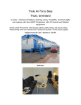
U. S. Army Post - Ft. Bliss, TX
52 lanes – Remove 20 82-70 Xli and install Edge
Day 1 – Tuesday, July 29, 2014 – Arrived early and unloaded tools and set-up tool shop behind
the Pinspotters that we are replacing – Lanes 1-20. Began removing all components necessary to
remove front ends and back ends of the old 82-70 Xli Pinspotters. Trucks came and we
unloaded.
We removed all components needed to start removing old Pinspotters except rear tie-down
plates and dealing with the wiring down Pinspotter legs for scoring/bumpers, etc.
Distributors, Sweeps, Pin Lights, Black tracks, Chassis, Chassis support, V-plates, PBL belt
tensioners, upsweep rails/boomerangs, E-Stop wireways and support brackets, hand rails, sweep
guards/curtain hanger brackets, PBL’s, Paddles and Light Ball Sensors, etc. – all back-end and
front end related components removed and stored. All hardware saved to give to the center.
Daily hours: 9 (me) + 16 (skilled) + 16 (laborer) = 41. Job hours: 9 + 16 + 16 = 41.
Day 2 – Wednesday, July 30, 2014 – We removed the old tie-down plates with a lot of trouble.
Had to grind many, as bolts just spinning. Removed old ball detects, hotdogs, tied-up sweep
links for shipping, banded tables up for removal, removed all wiring to separate front ends saving
scoring wire to 3 QT and camera and home run for Pinspotter MCU. Removed all back ends to
the parking lot.
We ran all the back end jack screws up all the way to be lying flat on the parking lot for shipping.
We had a lot of trouble doing so, as many jack screws were frozen. We cleaned-up the back end
area completely, behind the old front ends. We removed all the old front ends to the parking lot.
All 40 pinspotters outside – 20 old anfd 20 new.
Rolled-up tools. Daily hours: 10 + 18 + 18 = 46. Job hours: 19 + 34 + 34 = 87.
Day 3 – Thursday, July 31, 2014 – Another great day today. Brought-up Lanes 1 and 20’s 7-10
lines, and drew a string across the 20 lanes and painted the 7-10 line on top of kickbacks.
Installed Unistrut hardware in position on kickbacks with gauge templates. Uncrated and placed
all front ends on kickbacks.
Set front end frame heights to 18 7/8” and centered over pindecks.
Set height and squeezed frames to center
Frames set to have about 3/16” of frame showing beyond the securing washer
We unpacked back ends, brought inside, and placed behind front ends.
We stayed late to get all new equipment inside, as weather forcast is calling for heavy rain/flood
warnings for tomorrow. Everything safely inside. Daily hours: 11 + 20 + 20 = 51. Job hours: 30
+ 54 + 54 = 138.
Day 4 – Friday, August 1, 2014 – We packed all of the old backends for shipping back to
Richmond on Monday.
We began packing the old front ends in a steady light rain. We got all but 4 skidded when the
steady light rain turned to monsoon.
We installed all 20 New backends, mating with the New front ends, which were secured in the
correct place yesterday. We had much trouble getting perfect dead-flush mating at rear and
dead perfect level elevation, so that all pulleys and PBL saddles are dead in line (up/down and
in/out) for easy install/removal, while at the same time achieving great single division catwalk
mating, and a wide double division between backend side-frames (9 7/8” – 10”) (old ones were 9
½” – WAY too narrow) so that mechanics can easily install/remove PBL unit. The existing
kickbacks are not all 6.25” from 7-10 line to rear of kickback. They go in and out as much as ¼”.
It worked-out well, as we drew a string across rears of kickbacks before starting, to identify the
offending kickbacks, so we could allow for them with less or extra washer spacing between
frontends and backends to maintain dead-straight alignment of backends. Back ends in a perfect
line and single division catwalks great:
Single Division Catwalks
Mating In/Out great
All 20 Backends Installed
Daily hours: 9 + 16 + 16 = 41. Job hours: 39 + 70 + 70 = 179.
Day 5 – Saturday, August 2, 2014 – It was raining hard at start of our day, but we pallet-jacked
the PSP Crates inside shop door and emptied each crate, placing the entire contents of a crate
behind a pair of lanes. All PSP Crate contents safely inside.
The rain stopped for a little while and we finished skidding the old Pinspotter front ends.
We installed the Ball Doors and shimmed Lifter Boomerangs onto Upsweep Rails (all openings
between frames at double division either 9 7/8” or 10” – great width for PBL installation/removal)
and installed (Lifters centered on Ball Doors) on 1-20.
We installed the pit lights and sweeps on 1-20. One Pit Light had two RH mounting brackets in it
instead of a RH and a LH, so we installed the LH one upside-down and ordered a LH (070-001908), and there were a total of 12 8-32 nuts for pit light (813-933-162) missing. Also ordered.
We removed the shipping bolts from Bins on 1-20 (and removed Bin Shipping Cotter Pins).
We re-located the PBL Bumper brackets and Bumpers to the TOP of the backend frames on 1-20,
instead of the bottoms of the frames, where they had to be located for shipping.
We performed the stroke of: Setting PBL Motor Pulleys at proper width, installing Chassis mount
plates,
installing Hotdogs, Mousetraps, Rudder Drive Pulleys, Shimmed Ratchets, and hanging PBL Belts
and Ratchet Drive belts on 1-20.
We removed all 60 shipping motor plugs and installed all 60 vent plugs.
We began installing Black Tracks to Upsweep Rails at the top and Downsweep Assembly at the
bottom (with lower bow-tie). Black Track is dead-center between Pinspotter Frames at top and
bottom, and dead-level at top and bottom.
Two pairs of lanes completed on Black Track. We broke-down all empty boxes, gathered all
trash, and removed to the dumpster. Daily Hours: 10 + 16 + 16 = 42. Job Hours: 49 + 86 + 86
= 221.
Day 6 – Monday, August 4, 2014 – Trucks came today to ship old pinspotters and chassis back to
Richmond. Loaded and sent on their way. We finished the black tracks on all lanes that we
started on Saturday. We installed the E-Stop boxes behind the guys installing Black Track. Level
with wireways and centered between wireways.
We began running Foul and Ball Lift wires underground and removing the old wire to return to
the center intact.
Old Ball Lift wire removed and new wire installed
Old Foul Wire removed and new Installed
They sent Xli foul wire for Xli Chassis-to-Foul Unit, but they have Radaray (as you can see above)
Left a message to see if Richmond wants me to use the Xli Foul Wire sent instead of the 4conductor Radaray wire. We have half the center re-wired underground. We started the long
stroke of installing: Sized Lifter-to-Ratchet rod (GREAT!! All sized (lifter rod) from factory for the
first time @ 15.5” center-to-center – the proper length 90+% of the time), Centered PBL
(centered on Upsweep rails at the top and on Lifter at the bottom), PBL Belts (adjusting carpet
drive pulleys for proper alignment), Centered PBL Belt Tensioners and springs, Shimmed Spring
Straps, Ratchet and Mousetrap belts, Mousetrap tension rods/springs, PBL rearward tension
rods/springs, and Ratchet Belt tensioner springs. 7 of 10 complete. Here Pictures of the process:
All Lined-up and Centered perfectly
Began adjusting Sweeps and Tables. I am going to leave several Sweeps and Tables raw for
Training School. Daily hours: 10 + 16 + 16 = 42. Job hours: 59 + 102 + 102 = 263.
Day 7 – Tuesday, August 5, 2014 – We cleaned the rear parking lot of all hardware from the
Pinspotters that were staged there. We finished running underground wire to Foul and Ball Lifts
up front. We found the 088-200-515 Adapters for converting Xli Foul cable to Radaray. We wired
comletely, the foul units and Ball Returns up front, checked underground with flashlight to be
sure all wires are out of harm’s way, buttoned-up capping and restored ball lift area to normal
(trap doors, Options Hoods and Access Panels, etc.). We returned all old wiring that we removed
from undergrounds to the Bowling Center. We installed Chassis mount brackets/plates.
We Installed PBL Guard uprights and installed the rear wireways to the center hole of the Chassis
mount plates.
We installed Light Ball Sensors and adjusted for proper Rudder and Paddle location.
Rudder Bisecting the stop-bumper
Paddle centered in door
All Light ball sensors needed no shimming for the Paddle to be centered, only slight in or out of
the Rudder in the aluminium Rudder housing was needed. All Rudder Arm ends were within 1/8”
of being flush to rear of the rear aluminium housing. Here is a picture of installed and centered
LBS:
We installed the Pinspotter Tie-Down Plates on all the Singles, using one plate per single, since
all the singles are close to one-another and dead-even. This allowed us to miss the old holes for
tie-down plates from the old Pinspotters (they used two plates since the backends at the singles
were too far apart to use one plate).
The doubles required us to drill new holes in the plates, because the holes provided were close
to the old tie-down plate holes. We drilled all the new holes in the 20 double-division plates
ready to install tomorrow. We finished static (will tweak under power) table and sweep adjusting
on 1-10 (we left 10 of each (11-20) RAW for Pinspotter Training School Monday, Tuesday,
Wednesday August 11, 12, 13). We prepared to install CE Ladders. Daily Hours: 9 + 16 + 16 =
41. Job hours: 68 + 118 + 118 = 304.
Day 8 – Wednesday, August 6, 2014 – We finished LBS install. On ALL: Boomerang clear of
frame bolt by 1/8” AND Rudder clear of Boomerang at even lane LBS stroke
We finished installing all Tie-Down Plates. We installed all Chassis. We installed all distributors.
We installed all Distributor O-Pans:
We began Final Wiring.
All Grounds to covers, wire harnesses, and Chassis connected.
Ran all connections to Chassis as shown above. Grounds connected.
Ran all cables and MCU daisey chain. Ran underground wire down Pinspotter leg.
Seven of ten Final Wirings complete. Waiting for Mask Cables to add into Odd Machine wireway.
We Installed CE Ladders and hand-rails at 6 of the 9 locations for this center.
Removed cardboard protection on carpets. Removed PBL guards from even backends. Brokedown all cardboard boxes and cleaned-up. Daily Hours: 10 + 16 + 8 = 34. Job Hours: 78 + 134
+ 126 = 338.
Day 9 – Thursday, August 7, 2014 – We finished final wiring and fired them up to let carpets run.
All good except combo motor gearbox leaking at bottom seal.
Assembly in Richmond is still trapping Mask Switch wires sometimes, when installing grounds:
We finished CE ladders. We tweaked the sweep travels and spot rods under power (things that
crank adjusting can’t get right). 10 of each left raw for Training School (I cleared that with
Center Manager). Adjusted LBS on 1-10 (11-20 left raw for Training School). Adjusted
distributors for height over Durabins, centering and clutch tension. Lubed Distributors. Had to
move a few Distributor Drive Housings inward on some odd Pinspotters, as drive rod balls were
bottoming-out on housing at 1 and 5 positions. We adjusted all PBL heights for ½” clearance
from a ball resting on Lifter. We installed all Ball Detects and reflectors on a stringline. All were
good regarding double-check with gauge - isolating front eyeballs from rear eyeballs.
We checked all ball lifts up front for on/off with Pinspotter and cycle/mechanic call. All good
except 11-12. This pair hasn’t recently been turned on and off by a Pinspotter. It is running and
beeping every day, since the Ball Lift board has no #1 post to attach the Ball Lift Control wire to.
The control wires go on terminals #1 and #2 of terminal strip J1. There is no #1 terminal screw
on the J1 terminal strip:
#1 on J1 is just an empty hole and J1 terminal strip broken
I told the center about the issue so they could order a new board. We addressed all the Chassis.
We installed new MCU and set all Chassis parameters at MCU up front at control desk – verifying
proper communications to new Pinspotters. We rebooted all the 3QT’s that we had disconnected
for the Pinspotter install. All came back up fine except 13-14 which was a bad 3QT. We installed
PBL guards. We installed Rear LBS guards.
We buttoned-down all wireways that we could (left even lane wireway open to install mask wires
on the way here from Richmond). All that is left to do is install the mask wires when they come
tomorrow, and install Ball Wiper cloths, install Chassis rear covers and Cover-Keepers, and test
scoring, foul cycle, etc. which I will do over the weekend – as Training School doesn’t start until
Monday. Daily hours: 10 + 16 + 16 = 42. Job hours: 88 + 150 + 142 = 380.
Day 10 – Friday, August 8, 2014 – We finished-up today. We received the Mask wires and
installed on 1-20 and tested – all good.
We installed the Center’s Ground Buss to the new Pinspotters, grinding paint off frames for a
good ground and securing.
We installed the Chassis Rear Guard after connecting the mask wire and buttoned-down the rest
of the wireway covers that had to be left off waiting for the final mask cable to go in.
We installed the curtains and positioned the curtain-protectors.
We cleaned the Pinspotter plastic parts and applied Armor-all. They look great.
Daily Hours: 10 + 16 + 16 = 42. Final Job Hours: 98 + 166 + 158 = 422. 21.1 Man-Hours per
lane.
Pinspotter Training (instructions for both Steel Table and Aluminum Table-types shown)
Sweep (82-70-style)
1. Loosen 4 long sweep rod jam nuts (2 on rod here and 2 on rod on the other side)
and the 2 short sweep rod
jam nuts, (getting about 12-14 threads showing (total)- combining the threads showing on both
sides of the long rods beyond the snug jam nuts, for equal “hang” position at zero degrees across
the center) make sure that female half of telescoping tube is screwed-in tight against the rod end
or jam nut.
2. Adjust first guard height over lane with threaded link (about 1.25” off lane),
1/4” or so, with threaded link bracket up or down,
3. Adjust 4-5-6 row height to
4. At rearmost position,
travel squareness with long sweep rods and overall travel with short sweep rod,
5. Check/readjust travel under power, 6. Tighten 6 jam nuts.
Table (Aluminum)
1. Table to lowest spotting point:
2. ACHIEVE - Parallel-5/16” (stabilizer rods/clevis) and flag:
adjust
3. Check respot cell situation – carburetor link lengths, and strike cam rod length
4. Reverse crank table to 6” off deck and adjust combination square adjustment:
5. Pin bottoms to 5/16” and adjust cup sizes for even hang, and spot rod for proper “toe,” (1/16”
clearance between the square head stop bolt and the stop):
6. Adjust individual cups on spot via spotting cup U-Bolts:
7. Adjust respot rod for proper respot cell action, 7. Pick up standing pins in respot cells and
adjust respot cells(tiny screw in cell using ¼” thin wrench) for proper pin “hang” from a closed
cell, 8. Fine-tune cups for perfect spotting under power. Adjust 1 st and 2nd guard as needed in Xli
MCU mode.
Pinspotter Training
Steel Table Xli or Edge
Sweeps
Step 1 – Loosen the 6 jam nuts (2 each) on each of the 3 sweep rods.
View from pindeck – looking up:
2 Jam nuts on the short travel rod and 2 each on the two long rods (7 pin side long rod
not shown)
Step 2 – Crank the sweep motor Counter-Clockwise to perfect GUARD position (all the
way DOWN and all the way OUT). Set the larger ends of the sweep gauge blocks under
the sweep near outer edges of the lane.
Loosen the bolt through the SLOT in the Triangular plate.
Hold the bolt and Telescoping Rod forward and tighten to set guard sweep height at the
size of the gauge.
Step 3 – Crank to 4-5-6 row and move the triangle plate UP or Down… (plate down =
Sweep up, plate up = Sweep down)
to achieve the gap represented by the SMALL side of Sweep Gauges as shown below.
Step 4 – Adjust the sweep left or right to CENTER over pindeck. Gaps from pindeck to
sweep should be near equal on both sides.
Step 5 – Crank sweep to rearmost point and adjust the evenness of the travel by
adjusting one of the Long rods.
Step 6 – Adjust the OVERALL travel with the SHORT sweep rod so that the sweep covers
about 15% of the rear of the 7-8-9-10 spots when looking from Pindeck.
Step 7 – Crank/Run sweep back to HOME and tighten the 6 jam nuts loosened in Step 1.
Run the sweep under power and adjust overall travel so the sweep travels rearward
PAST the reference lines behind the 7 and 10 spots, BUT SHORT of the end of the
Pindeck. Set all Guard positions for 1st and 2nd Guard and record positions in your
manual.
Light Ball Sensors
Step 1 – Install Light Ball Sensor unit CENTERED between the Kickbacks.
Be sure that the RUDDER ARM bisects the Rudder arm stop-bumper (Up and Down
adjustment) Shim the Light Ball Sensor FRAME at the TOP two attaching bolts to RAISE
the rudder arm or at the BOTTOM two frame attaching bolts to LOWER the rudder arm,
so that the rudder arm BISECTS the rudder arm stop bumpers on a 45 degree angle.
Adjust the rudder arm IN OR OUT of it’s housing to achieve a CENTERED PADDLE within
the ball door opening.
Be sure that the LIFTER height is about 1/8” above the ball door weldment:
Adjust the LIFTER height by shortening or lengthening the LIFTER ROD.
Step 2 – Snug the RESET CAMS up and out of your way
Snug the POWER STROKE INDUCING ARC CAM forward and centered out of your way,
and then make the RUDDER TRAVEL WIDENING/NARROWING ECCENTRIC PLATE as
least eccentric as possible (shaft as far as possible toward the center of the rudder drive
pulley).
Step 3 – Adjust the length of the RUDDER TRAVEL CENTERING ROD to fit onto the
Rudder Drive pulley stud, evenly changing the length from both ends of the rod. Run
under power and observe the travel of the Rudder Arm relative to the Stop Bumpers.
Adjust the length of the RUDDER TRAVEL CENTERING ROD to CENTER the travel of the
Rudder Arm as well as possible and tighten jam nuts. Adjust the RUDDER TRAVEL
WIDENING/NARROWING ECCENTRIC PLATE to achieve 1/16” of OVERTRAVEL of the
POWER STROKE INDUCING ARC CAM as the rudder arm dwells momentarily on each
rudder stop bumper, and tighten both plate securing nuts.
Step 4 – Stop the LBS when Rudder travel is on one of the travel-stop bumpers. Adjust
the POWER STROKE RESET CAM for that side to be within 1/32” of the POWER STROKE
CAM FOLLOWER. Repeat for the other side. Then tweak the POWER STROKE RESET
CAMS with a pry bar, to obtain BOTH a FULL RESET of the Power Stroke Cam Follower,
AND YET allow the rudder arm to fully reach it’s rudder stop bumper. THERE IS ONLY
ONE PLACE that the Reset Cams can be positioned that will achieve BOTH a FULL RESET
of the Power Stroke Cam Follower AND a complete Rudder Travel ALL THE WAY to the
Rudder stop bumper.
Step 5 – Position the POWER STROKE INDUCING ARC CAM
To within 1/8” and centered between the two POWER STROKE CAM FOLLOWERS. BE
CERTAIN THAT THE ARC CAM DOES NOT TOUCH EITHER POWER STROKE CAM
FOLLOWERS DURING ROUTINE MOTION. Run under power and inhibit the rudder arm
listening for a strong “CLICK” sound as the power stroke is induced. A change in the
angle of the Arc Cam may be needed to induce a solid “click” for BOTH odd and even
sides. YOU ARE NOT FINISHED until: 1. Overtravel of Arc Cam is 1/16” and fairly
even on both odd and even sides, 2. POWER STROKE RESET CAMS reset the power
stroke cam followers COMPLETELY – AND the rudder arm reaches and dwells on BOTH
rudder arm stop bumpers. 3. Arc Cam is VERY close to, but NOT touching either Power
Stroke Cam Follower during routine motion. 4. There is a solid “CLICK” as the power
stroke is induced on BOTH SIDES.
Steel Tables
Step 1 – Crank the Table to the spotting position holding down the spot latch, so that
pins are delivered to cups and table goes all the way to the pindeck. The table is at it’s
lowest point when these three points are in a straight line.
Step 2 – Make the table PARALLEL to the pindeck by adjusting the Table Tie-Rods, so
that when measuring under the 1, 8, and 10 Pin button-head respot cell pivot bolts, all
three corner are THE SAME distance from the pindeck – PARALLEL to the pindeck.
Adjust the CLEVIS length, so that the table is 5/16” from the pindeck. We call this
PARALLEL-5/16”. The Table should be PARALLEL TO the pindeck AND 5/16” from the
pindeck. A bit higher than 5/16” OK. Lower than 5/16” not OK.
Step 3 – “Flag” the table by inserting table flags into the table at the 1, 7, and 10 pin
respot cell locations as shown below, and move the table as needed (one side at a time),
by loosening the 3 bolts on each side of the table, that connect the steel table to the
table weldments. Locate the table so that the table flags point to the center of the 1, 7,
and 10 spots.
Check and adjust respot cells and cell-opening cam follower at this point if necessary. All
cells should be fully open with a bit of “slop” in the rear fingers, as we discussed.
Step 4 – When the table is “Parallel 5/16” and flagged, crank the table BACKWARDS
(clockwise) until the PIN BOTTOMS are 5/16” from the pindeck. At this point, you should
have about a 1/16” gap between the square-head stop bolt and the stop.
(First be certain that about 4 threads are showing between square head and housing).
Check for any low or high hanging pins and adjust cups accordingly. Adjust the length of
the SPOT ROD to achieve the 1/16” gap, between Square Head Stop Bolt and the Stop.
Step 5 – Crank the table a bit lower, with pins hovering over the spots (about 1/8” 3/16” from spots), and adjust each individual spotting cup to CENTER the pin bottom
over the spot BOTH Left-To-Right
AND Front-To-Back
Loosen BOTH TOP spotting cup bolts until cup is hanging freely. Tap the cup and block
evenly - right or left until centered. Choose ONE U-BOLT and tighten top nut of that Ubolt until the pin bottom is centered over the spot from front-to-back, then tighten lower
and upper nuts of that U-Bolt EQUALLY in small increments, to maintain the cups
centered-from-front-to-back location until the cup is secured in place by that one U-Bolt.
Then tighten the loose U-Bolt’s nuts in such a way as to MATCH THE NUMBER OF
THREADS showing beyond the TIGHTENED U-BOLT’S upper and lower nuts for even
pressure on the spotting cup. Repeat for all cups. Test under power and adjust individual
cups if one or a few cups are off spot. If ALL cups are good from front-to back but ALL
are a bit in front of or behind spots (by about the same amount – commonly possible
due to cranking vs. running under power) – then tweak SPOT ROD to adjust ALL cups a
bit forward or back. Check respot rod adjustment for a gap between the pawl and the
center of the W-Shaped respot cell shifter of about 5/16”-3/8”. Test respotting action
under power looking for a smooth opening and closing/ locking of cells on the pins. If
cells don’t close all the way and lock soundly – decrease Pawl gap. If the cells slap the
pins too hard and struggle to unlock when trying to open – increase pawl gap. Stop table
at zero with pins in all cells and check the “hang” of the pins in the grippers. Pins should
be held near TOP of the top red stripe. Adjust individual cells as needed.
Distributors (Non-Edge)
First- check for proper post shimming to provide about 3/16” clearance between front underside
belt guide and Bin Frame/Durabin at 8-9 position and check for proper “balance” by removing
the two rear springs and checking that distributor doesn’t swing toward 7 or 10 side. Distributor
should be balanced and Orientor pan should be level.
Squeeze to obtain a 5 ½” pan opening…
and ¼” or so clearance from level O-pan to pin wheel.
THEN:
1. Center distributor via safety link. 2. Make sure big spring front hanger bracket is straight and
not bent rearward and that the jam nut trapping this spring hanger bracket is tight.
3. Make sure that pin seating rods are inward to within 1/8” of passing pinwheel cleats (7).
4. Adjust REAR kidney up-down adjustment. Lower/raise lower rear adjusting nut to be adjusted
so that a head-first pin is flush with kidney while a butt-first pin is a bit loose when contacting
kidney, and upper rear kidney adjusting nut is adjusted for a ¾”-7/8” PIN DROP from kidney to
Orientor Pan. 5. Adjust INNER kidney nuts so that the belly of a BUTT-FIRST strikes O-Pan just
PAST center of pan, and belly of a HEAD-FIRST pin strikes O-Pan just SHORT OF the center of the
O-Pan. 6. Check clutch spring for proper tension. “Feel” clutch tension by rotating inner clutch
facing rearward. ¾ to 7/8 of a turn on the clutch spring should yield proper clutch tension, but
feel this tension, as contamination may require more than the recommended tension until such
time that the clutch can be cleaned. 7. Index distributor to 7-pin corner. Test butt-first
orientation the head-first orientation on ALL 7 CLEATS of the pin wheel. Look for NO
HEASITATION as a pin proceeds down distributor belt. Repeat for 10-pin corner. If pins hesitate,
pry upward slightly on the support under the distributor belt just beyond the O-Pan, as it may be
too concave to allow distributor belt to “grab” the pin and convey it forward. 8. Be sure that the
stop bracket lines-up exactly with the tab on the inner (gold) clutch plate at ALL pin positions. 9.
Put machine on continuous cycle and observe/double-check for smooth orientation and
progression from position-to-position.
Review the entire Service Manual, covering all the adjustments we have made so far,
and where they can be found in the manual, as well as PM pages, Parts Drawings,
Troubleshooting, Lubrication, Distributor Manual, MCU Manual, PBL Manual, Chassis
Manual, Motor Manual, Stop Sheets, Frames-per-Stop, and all other Service Manual
sections. Cover shop set-up and review special tools.
Train on Cameras and Scoring as needed. Check/adjust the ball detects on the Q-Vision
Cameras. Show how to load and send Pinspotter Default Parameters, and how to scopein all cameras through Conqueror. Cover all other major scoring components and
network diagram for the center.
Removed and reinstalled a cushion and bounce board/carpet assembly (5 day course).
Review shuttle adjustments (gap and stop) and cover shuttle rod intricacies. Change a
Pinspotter chassis (testing spare) and load all MCU settings which we have recorded in
the Chassis Manual including Guard settings. Change a PBL showing eccentric
adjustments possible, and discussing importance of upper and lower PBL centering
relative to upsweep rails and lifter.
Completely lube pinspotter front ends and run. Adjust all foul detectors and test. Check
all bumpers.
Perform the entire PM schedule and clean Pinspotters (5 day course).
QAMF Edge Training School
Final Exam
Table and Front End
Circle correct answers
1. Table “flags” are used to do what?
A. Set table height
B. Spot pins
C. Center table over pindeck
2. At it’s lowest spotting position, table should be parallel to pindeck and how far
above the pindeck?
A. 1”
B. 5/16” C. 1/8”
3. The solenoid fires right before the table is about to:
A. pick up standing pins
B. set a new rack of pins.
4. When the solenoid fires, it does three things. Which below is NOT one of those
three things:
A. Unblock the shuttle
B. Induce a long table stroke
C. Cause cups to turn downward
D. Open respot cells
Figure 1
5. In figure #1, item 11 is the respot rod. What is it’s function?
A. Used to raise or lower table
B. Used to open and close respot cells
C. Used to level table
6. In figure #1, item 9 is called what?
A. Table leveling tie rod
B. Sweep travel rod
C. Spot rod
Figure 2
7. Figure 2 is of what component?
A. Table drive assembly
B. Table motor assembly
C. Table torque tube assembly
8. In Figure #2, item 4 is called the clevis. What is it’s function.
A. Used to raise or lower table
B. Used to open and close respot cells
C. Used to level table
9. Table adjustments can be done in any order.
A. True
B. False
10. When spotting, the pin bottoms should strike the pindeck:
A. Slightly toe-first
B. Flat
C. Slightly heel-first
11. The length of which rod determines when the spotting cups shift rearward,
releasing pins in the spotting motion:
A. Spot rod
B. Respot rod
C. Table tie-rod
12. The length of which rod determines when the respot cells open and close:
A. Spot rod
B. Respot rod
C. Table tie-rod
13. The length of which rods determines the levelness of the table:
A. Spot rod
B. Respot rod
C. Table tie-rod
14. The spotting cups are all individually adjustable.
A. True
B. False
15. When changing a spotting cup, the table should be positioned:
A. As high as it will go
B. As low as it will go
C. Pin bottoms hovered over spots
16. How many respot cells are on a pinspotter?
A. 2
B. 6
C. 10
17. How many different respot cell types are on a pinspotter?
A. 2
B. 6
C. 10
18. How many respot cells on a pinspotter have carburetor links attached to
them?
A. 2
B. 6
C. 10
19. Respot cells should hold a pin just above the top red stripe/Crown on the
pin.
A. True
B. False
20. During which cycle are respot cells called upon to operate?
A. Strike cycle
B. 1st ball cycle
C. Foul cycle
QAMF Edge Training School
Sweep, Back End, and PBL Circle correct answers
1. The sweeps lowest point in the sweeping motion is:
A. At guard position
B. Over the 4-5-6 row of pin spots
C. All the way at the back of the pindeck
Figure 3
2. In Figure 3, the position of the bolt (item 6) in the slot of the bracket (item 8)
determines the sweep’s height where?
A. At guard position
B. Over the 4-5-6 row of pin spots
C. All the way at the back of the pindeck
Figure 4
3. In figure 4. The bracket shown is bolted to the side-frame and it adjusts up or
down to change the sweep height during the sweeping motion. Where do you
position the sweep to make this adjustment?
A. At guard position
B. Over the 4-5-6 row of pin spots
C. All the way at the back of the pindeck
Figure 5
4. Item 48 in figure 5 is the sweep travel rod. This rod’s length determines how far
the sweep travels rearward. Where do you position the sweep to make this
adjustment?
A. At guard position
B. Over the 4-5-6 row of pin spots
C. All the way at the back of the pindeck
5. When the sweep is at guard position, it should be:
A. 1 1/8” – 1 3/16” above the lane surface
B. About 3/16” above the pindeck
C. Even with the rear tailplank reference marks
6. When the sweep is over the 4-5-6 row of pin spots, it should be:
A. 1 1/8” – 1 3/16” above the lane surface
B. About 3/16” above the pindeck
C. Even with the rear tailplank reference marks
7. When the sweep is running under power, it’s rear-most position should be:
A. 1 1/8” – 1 3/16” above the lane surface
B. About 3/16” above the pindeck
C. Even with the rear tailplank reference marks
8. The sweep is adjustable from right-to-left over the pindeck.
A. True
B. False
9. It is possible to adjust the travel of the 7-pin side of the sweep and the 10-pin
side of the sweep independently.
A. True
B. False
10. If a sweep-table interlock occurs because a pin gets trapped between the
sweep and the flat-gutter, this usually is an indication of what?
A. Sweep is traveling too far rearward
B. Sweep is not traveling far enough rearward
11. The assembly that stops the ball as the ball leaves the pindeck is called:
A. The carpet
B. The bounce plate
C. The cushion
12. The item which conveys the pins back to the pin elevator is called:
A. The carpet
B. The bounce plate
C. The cushion
13. The “hidden” assembly which funnels the ball toward the ball exit is called:
A. The carpet
B. The bounce plate
C. The cushion
14. The back end motor drives three pinspotter components. They are the PBL
system, the pin elevator, and what?
A. The sweep
B. The table
C. The distributor
Figure 6
Figure 6 is the light ball sensor assembly. Locate items 19, 25, 39, and 52. Each
item does one of the four choices below.
15. Item 19 does what?
A. Centers the rudder/paddle travel
B. Induces a “power stroke”
C. Resets the power stroke cam follower to “normal stroke” D.
Narrows or widens the rudder/paddle travel
16. Item 25 does what?
A. Centers the rudder/paddle travel
B. Induces a “power stroke”
C. Resets the power stroke cam follower to “normal stroke” D.
Narrows or widens the rudder/paddle travel
17. Changing the length of item 39 does what?
A. Centers the rudder/paddle travel
B. Induces a “power stroke”
C. Resets the power stroke cam follower to “normal stroke” D.
Narrows or widens the rudder/paddle travel
18. Adjusting item 52 does what?
A. Centers the rudder/paddle travel
B. Induces a “power stroke”
C. Resets the power stroke cam follower to “normal stroke” D.
Narrows or widens the rudder/paddle travel
19. The same belt which drives the carpet, drives the PBL system.
A. True
B. False