1
Agilent Technologies 85325A R/Q/U/V/W
Millimeter Subsystem
Agilent Technologies 85326A Millimeter-Wave
Interface Kit
Operating and Service
Manual
Manual part number: 85325-90061
Printed in USA
November 1999
Revision 1.0
Notice
The information contained in this document is subject to change without
notice.
Agilent Technologies makes no warranty of any kind with regard to this
material, including, but not limited to, the implied warranties of
merchantability and fitness for a particular purpose. Agilent Technologies
shall not be liable for errors contained herein or for incidental or
consequential damages in connection with the furnishing, performance, or
use of this material.
Agilent Technologies assumes no responsibility for the use or reliability of
its software on equipment that is not furnished by Agilent Technologies.
This document contains proprietary information which is protected by
copyright. All rights are reserved. No part of this document may be
photocopied, reproduced, or translated to another language without prior
written consent of Agilent Technologies.
RESTRICTED RIGHTS LEGEND
Use, duplication, or disclosure by the U.S. Government is subject to
restrictions as set forth in subparagraph (c)(1)(ii) of the Rights in Technical
Data and Computer Software clause at DFARS 252.227-7013 for DOD
agencies, and subparagraphs (c)(1) and (c)(2) of the Commercial Computer
Software Restricted Rights clause at FAR 52.227-19 for other agencies.
Agilent Technologies, Inc.
1400 Fountaingrove Parkway
Santa Rosa, CA 95403-1799, U.S.A.
© Copyright Agilent Technologies, Inc. 2000
ii Agilent 85325A Operating and Service Manual
What You’ll Find in This Manual
Chapter 1
•
Installation
Chapter 2
•
Operation
Chapter 3
•
General Information
Chapter 4
•
Performance Verification
Chapter 5
•
Timebase Check and Adjustment
Chapter 6
•
Service
Appendix A
•
Using the HP 8340/41 in Your System
Appendix B
•
Connecting the Waveguide Properly
Agilent 85325A Operating and Service Manual iii
Warranty
Custom systems are warranted by contractual agreement between Agilent
Technologies and the customer.
Certification
Agilent Technologies, Inc., certifies that this product met its published
specifications at the time of shipment from the factory. Agilent Technologies
further certifies that its calibration measurements are traceable to the
United States National Institute of Standards and Technology (NIST,
formerly NBS), to the extent allowed by the Institute’s calibration facility,
and to the calibration facilities of other International Standards
Organization members.
Warranty
This Agilent Technologies system product is warranted against defects in
materials and workmanship for a period corresponding to the individual
warranty periods of its component products. Instruments are warranted for a
period of one year. During the warranty period, Agilent Technologies will, at
its option, either repair or replace products that prove to be defective.
Warranty service for products installed by Agilent Technologies and certain
other products designated by Agilent Technologies will be performed at
Buyer’s facility at no charge within Agilent Technologies service travel
areas. Outside Agilent Technologies service travel areas, warranty service
will be performed at Buyer’s facility only upon Agilent Technologies’ prior
agreement and Buyer shall pay Agilent Technologies’ round trip travel
expenses. In all other areas, products must be returned to a service facility
designated by Agilent Technologies.
For products returned to Agilent Technologies for warranty service, Buyer
shall prepay shipping charges to Agilent Technologies and Agilent
Technologies shall pay shipping charges to return the product to Buyer.
However, Buyer shall pay all shipping charges, duties, and taxes for products
returned to Agilent Technologies from another country.
Agilent Technologies warrants that its software and firmware designated by
Agilent Technologies for use with an instrument will execute its
programming instructions when properly installed on that instrument.
Agilent Technologies does not warrant that the operation of the instrument,
or software, or firmware will be uninterrupted or error free.
LIMITATION OF WARRANTY. The foregoing warranty shall not apply
to defects resulting from improper or inadequate maintenance by Buyer,
Buyer-supplied software or interfacing, unauthorized modification or
misuse, operation outside of the environmental specifications for the
product, or improper site preparation or maintenance.
iv Agilent 85325A Operating and Service Manual
NO OTHER WARRANTY IS EXPRESSED OR IMPLIED. AGILENT
TECHNOLOGIES SPECIFICALLY DISCLAIMS THE IMPLIED
WARRANTIES OR MERCHANTABILITY AND FITNESS FOR A
PARTICULAR PURPOSE.
EXCLUSIVE REMEDIES. THE REMEDIES PROVIDED HEREIN ARE
BUYER’S SOLE AND EXCLUSIVE REMEDIES. AGILENT
TECHNOLOGIES SHALL NOT BE LIABLE FOR ANY DIRECT,
INDIRECT, SPECIAL, INCIDENTAL, OR CONSEQUENTIAL
DAMAGES, WHETHER BASED ON CONTRACT, TORT, OR ANY
OTHER LEGAL THEORY.
YEAR 2000. Agilent Technologies warrants that each Agilent Technologies
hardware, software, and firmware product on Agilent Technologies’
Corporate Price List (dated July 1, 1998 or later) delivered under the
product’s contract of sale will be able to accurately process date data
(including, but not limited to, calculating, comparing, and sequencing) from,
into, and between the twentieth and twenty-first centuries, and the years
1999 and 2000, including leap year calculations, when used in accordance
with the product documentation provided that all other products (that is,
hardware, software, firmware) used in combination with such Agilent
Technologies product(s) properly exchange date data with it. If the
agreement requires that specific Agilent Technologies products must
perform as a system in accordance with the foregoing warranty, then that
warranty will apply to those Agilent Technologies products as a system, and
Customer retains sole responsibility to ensure the year 2000 readiness of its
information technology and business environment. The duration of this
warranty extends through January 31, 2001.
The remedies available under this warranty will be defined in, and subject to,
the terms and limitations of the warranties contained in the contract of sale.
To the extent permitted by local law, this warranty applies only to branded
Agilent Technologies products and not to products manufacture by others
that may be sold or distributed by Agilent Technologies. Nothing in this
warranty will be construed to limit any rights or remedies provided
elsewhere in the contract of sale with respect to matters other than year 2000
compliance.
Assistance
Product maintenance agreements and other customer assistance agreements
are available for Agilent Technologies products.
For assistance, call your local Agilent Technologies Sales and Service Office
(refer to “Service and Support” on page vi).
Agilent 85325A Operating and Service Manual v
Service and Support
Any adjustment, maintenance, or repair of this product must be performed
by qualified personnel. Contact your customer engineer through your local
Agilent Technologies Service Center. You can find a list of local service
representatives on the Web at:
http://www.agilent-tech.com/services/English/index.html
If you do not have access to the Internet, one of these centers can direct you
to your nearest representative:
United States:
Test and Measurement Call Center
(800) 452 4844 (toll-free in US)
Canada:
(905) 206 4725
Europe:
(31 20) 547 9900
Japan:
Measurement Assistance Center
(81) 426 56 7832
(81) 426 56 7840 (FAX)
Latin America:
(305) 267 4245, (305) 267-4220
(305) 267 4288 (FAX)
Australia/New Zealand:
1 800 629 485 (Australia)
0800 738 378 (New Zealand)
(61 3) 9210 5489 (FAX)
Asia-Pacific:
(852) 2599 7777
(852) 2506 9285 (FAX)
vi Agilent 85325A Operating and Service Manual
Safety and Regulatory Information
Review this product and related documentation to familiarize yourself with
safety markings and instructions before you operate the instrument. This
product has been designed and tested in accordance with international
standards.
WARNING
The WARNING notice denotes a hazard. It calls attention to a procedure,
practice, or the like, that, if not correctly performed or adhered to, could result
in personal injury. Do not proceed beyond a WARNING notice until the
indicated conditions are fully understood and met.
CAUTION
The CAUTION notice denotes a hazard. It calls attention to an operating
procedure, practice, or the like, which, if not correctly performed or adhered
to, could result in damage to the product or loss of important data. Do not
proceed beyond a CAUTION notice until the indicated conditions are fully
understood and met.
Instrument Markings
!
When you see this symbol on your instrument, you should refer to the instrument’s
instruction manual for important information.
This symbol indicates hazardous voltages.
The laser radiation symbol is marked on products that have a laser output.
This symbol indicates that the instrument requires alternating current (ac) input.
The CE mark is a registered trademark of the European Community. If it is
accompanied by a year, it indicates the year the design was proven.
The CSA mark is a registered trademark of the Canadian Standards Association.
1SM1-A
This text indicates that the instrument is an Industrial Scientific and Medical Group 1
Class A product (CISPER 11, Clause 4).
This symbol indicates that the power line switch is ON.
This symbol indicates that the power line switch is OFF or in STANDBY position.
Agilent 85325A Operating and Service Manual vii
Safety Earth
Ground
This is a Safety Class I product (provided with a protective earthing
terminal). An uninterruptible safety earth ground must be provided from the
main power source to the product input wiring terminals, power cord, or
supplied power cord set. Whenever it is likely that the protection has been
impaired, the product must be made inoperative and secured against any
unintended operation.
Before Applying Power
Verify that the product is configured to match the available main power
source as described in the input power configuration instructions in this
manual. If this product is to be powered by autotransformer, make sure the
common terminal is connected to the neutral (grounded) side of the ac power
supply.
viii Agilent 85325A Operating and Service Manual
Declaration of Conformity
This is to certify that this product meets the radio frequency interference
requirements of Directive FTZ 1046/1984. The German Bundespost has
been notified that this equipment was put into circulation and has been
granted the right to check the product type for compliance with these
requirements.
If test and measurement equipment is operated with unshielded cables
and/or used for measurements on open set-ups, the user must insure that
under these operating conditions, the radio frequency interference limits are
met at the border of his premises.
Model Agilent 85325A
and
Model Agilent 85326A
Hiermit wird bescheinigt, dass dieses Gert/System in bereinstimmung mit
den Bestimmungen von Postverfgung 1046/84 funkentst"rt ist.
Der Deutschen Bundespost wurde das Inverkehrbringen dieses
Gertes/Systems angezeight und die Berechtigung zur berprfung der Serie auf
Einhaltung der Bestimmungen eingerumt.
Zustzinformation fr Mess-und Testgerte:
Werden Mess- und Testgerte mit ungeschirmten Kabeln und/oder in offenen
Messaufbauten verwendet, so ist vom Betreiber sicherzustellen, dass die
Funk-Entst"rbestimmungen unter Betriebsbedingungen an seiner Grundstcksgrenze eingehalten werden.
Agilent 85325A Operating and Service Manual ix
Typeface Conventions
•
Used to emphasize important information:
Use this software only with the Agilent 00000X.
•
Used for the title of a publication:
Refer to the Agilent 85325A Operating and Service Manual.
•
Used to indicate a variable:
Type LOAD BIN filename.
Instrument Display
•
Used to show on-screen prompts and messages that you will see on the
display of an instrument:
The Agilent 00000X will display the message CAL1 SAVED.
[Keycap]
•
Used for labeled keys on the front panel of an instrument or on a
computer keyboard:
Press [Return].
{Softkey}
•
Used for simulated keys that appear on an instrument display:
Press {Prior Menu}.
User Entry
•
Used to indicate text that you will enter using the computer keyboard;
text shown in this typeface must be typed exactly as printed:
Type LOAD PARMFILE
•
Used for examples of programming code:
Italics
#endif // ifndef NO_CLASS
Path Name
•
Used for a subdirectory name or file path:
Edit the file usr/local/bin/sample.txt
Computer Display
•
Used to show messages, prompts, and window labels that appear on a
computer monitor:
The Edit Parameters window will appear on the screen.
•
Used for menus, lists, dialog boxes, and button boxes on a computer
monitor from which you make selections using the mouse or keyboard:
Double-click EXIT to quit the program.
x Agilent 85325A Operating and Service Manual
Contents
1.
Installation
Required Equipment . . . . . . . . . . . . . . . . . . . . . . . . . . . . . . . . . . . . . . . . 1-2
Table 1-1. Equipment Required . . . . . . . . . . . . . . . . . . . . . . . . . . . . 1-2
Initial Setup . . . . . . . . . . . . . . . . . . . . . . . . . . . . . . . . . . . . . . . . . . . . . . . 1-3
Figure 1-1. Initial Setup . . . . . . . . . . . . . . . . . . . . . . . . . . . . . . . . . 1-3
Using an HP/Agilent 8340/41 RF Source . . . . . . . . . . . . . . . . . . . . 1-3
Connecting the Waveguide . . . . . . . . . . . . . . . . . . . . . . . . . . . . . . . . 1-3
10 MHz Reference Connection . . . . . . . . . . . . . . . . . . . . . . . . . . . . 1-4
Receiver Settings . . . . . . . . . . . . . . . . . . . . . . . . . . . . . . . . . . . . . . . . . . 1-5
Setting Up the Receiver . . . . . . . . . . . . . . . . . . . . . . . . . . . . . . . . . . 1-5
Table 1-2. Rf Source DENOM Value Table . . . . . . . . . . . . . . . . . . . 1-6
Table 1-3. Lo Source Multiplier DENOM Table . . . . . . . . . . . . . . . 1-7
Mixer LO Power Level Adjustment . . . . . . . . . . . . . . . . . . . . . . . . . . . . 1-8
Initial Setup . . . . . . . . . . . . . . . . . . . . . . . . . . . . . . . . . . . . . . . . . . . 1-8
Initial Fixed Attenuator Value Selections . . . . . . . . . . . . . . . . . . . . . 1-8
Table 1-4. Selecting Agilent 85326A Reference and
Test Attenuation . . . . . . . . . . . . . . . . . . . . . . . . . . . . . . . . . . . . . 1-9
Figure 1-2. Reference Attenuator Installation . . . . . . . . . . . . . . . . 1-10
Figure 1-3. Test Attenuator Installation . . . . . . . . . . . . . . . . . . . . 1-10
Adjustment Procedures . . . . . . . . . . . . . . . . . . . . . . . . . . . . . . . . . . . . . 1-11
Procedure 1 . . . . . . . . . . . . . . . . . . . . . . . . . . . . . . . . . . . . . . . . . . . 1-11
Figure 1-4. Measuring LO Power from the Reference Module . . . 1-11
Figure 1-5. Reference Mixer Connections . . . . . . . . . . . . . . . . . . . 1-13
Figure 1-6. LO Power Measurement Point for Test Module . . . . . 1-13
Procedure 2 . . . . . . . . . . . . . . . . . . . . . . . . . . . . . . . . . . . . . . . . . . . 1-14
Mixer Operational Check . . . . . . . . . . . . . . . . . . . . . . . . . . . . . . . . . . . 1-16
Figure 1-7. Test Mixer Connections . . . . . . . . . . . . . . . . . . . . . . . 1-17
When Using an HP/Agilent 8350 LO Source . . . . . . . . . . . . . . . . 1-18
Saving the Setup . . . . . . . . . . . . . . . . . . . . . . . . . . . . . . . . . . . . . . . . . . 1-19
Final Installation . . . . . . . . . . . . . . . . . . . . . . . . . . . . . . . . . . . . . . . . . . 1-20
Figure 1-8. Leveling Control Cables . . . . . . . . . . . . . . . . . . . . . . . 1-20
Figure 1-9. Agilent 85325A/85326A Installation Block Diagram
(Coupled Reference) . . . . . . . . . . . . . . . . . . . . . . . . . . . . . . . . 1-21
Figure 1-10. Agilent 85325A/85326A Visual Installation Diagram
(Coupled Reference) . . . . . . . . . . . . . . . . . . . . . . . . . . . . . . . . 1-22
Figure 1-11. Agilent 85325A/85326A Installation Block Diagram
(Radiated Reference) . . . . . . . . . . . . . . . . . . . . . . . . . . . . . . . . 1-23
If Using an HP/Agilent 8340/41 RF Source . . . . . . . . . . . . . . . . . . 1-23
Connecting the Waveguide . . . . . . . . . . . . . . . . . . . . . . . . . . . . . . . 1-23
Proper Torque for Coax Connections . . . . . . . . . . . . . . . . . . . . . . . 1-24
Table 1-5. Proper Connector Torque . . . . . . . . . . . . . . . . . . . . . . . 1-24
Agilent Technoligies 85325A Operating and Service Manual Contents-1
Turn ON AC Power . . . . . . . . . . . . . . . . . . . . . . . . . . . . . . . . . . . . . 1-24
2.
Operation
Mixer Operating Parameters . . . . . . . . . . . . . . . . . . . . . . . . . . . . . . . . . .
Maximum RF Input Power . . . . . . . . . . . . . . . . . . . . . . . . . . . . . . . .
Maximum LO Input Power . . . . . . . . . . . . . . . . . . . . . . . . . . . . . . . .
Required LO Power . . . . . . . . . . . . . . . . . . . . . . . . . . . . . . . . . . . . . .
Connector Care . . . . . . . . . . . . . . . . . . . . . . . . . . . . . . . . . . . . . . . . .
Proper Waveguide Connector Alignment . . . . . . . . . . . . . . . . . . . . .
3.
General Information
Chapter Contents . . . . . . . . . . . . . . . . . . . . . . . . . . . . . . . . . . . . . . . . . . .
Product Description . . . . . . . . . . . . . . . . . . . . . . . . . . . . . . . . . . . . . . . . .
Specifications . . . . . . . . . . . . . . . . . . . . . . . . . . . . . . . . . . . . . . . . . . . . . .
About Specifications . . . . . . . . . . . . . . . . . . . . . . . . . . . . . . . . . . . . .
Table 3-1. R, Q, and U Band System Level Specifications . . . . . . . .
Table 3-2. V and W Band System Level Specifications . . . . . . . . . . .
MM-Wave Source and Mixer Characteristics . . . . . . . . . . . . . . . . . . . . .
Table 3-3. MM-Wave Source Information . . . . . . . . . . . . . . . . . . . .
Table 3-4. MM-Wave Mixer Information . . . . . . . . . . . . . . . . . . . . .
Supplied Equipment . . . . . . . . . . . . . . . . . . . . . . . . . . . . . . . . . . . . . . . . .
Table 3-5. Supplied Parts . . . . . . . . . . . . . . . . . . . . . . . . . . . . . . . . .
Maximum RF Cable Lengths . . . . . . . . . . . . . . . . . . . . . . . . . . . . . . . . . .
Figure 3-1. LS, LR, and LT Cables . . . . . . . . . . . . . . . . . . . . . . . . . .
Table 3-6. Maximum Cable Lengths (meters) . . . . . . . . . . . . . . . . .
Formulas for Cable Length Maximums . . . . . . . . . . . . . . . . . . . . . .
Figure 3-2. LS, LR, LT Cable Lengths, Example . . . . . . . . . . . . . . . .
4.
2-2
2-2
2-2
2-2
2-2
2-2
3-1
3-1
3-2
3-2
3-2
3-3
3-4
3-4
3-4
3-5
3-5
3-6
3-6
3-6
3-7
3-7
System Performance Verification
Introduction . . . . . . . . . . . . . . . . . . . . . . . . . . . . . . . . . . . . . . . . . . . . . . .
Recommended Test Equipment . . . . . . . . . . . . . . . . . . . . . . . . . . . . . . . .
Non-Banded Equipment . . . . . . . . . . . . . . . . . . . . . . . . . . . . . . . . . .
Table 4-1. Recommended Test Equipment (non-banded) . . . . . . . . .
Band-Dependent Equipment . . . . . . . . . . . . . . . . . . . . . . . . . . . . . . .
Table 4-2. Recommended Test Equipment (banded) . . . . . . . . . . . .
Receiver Performance Verification . . . . . . . . . . . . . . . . . . . . . . . . . . . . .
Overview . . . . . . . . . . . . . . . . . . . . . . . . . . . . . . . . . . . . . . . . . . . . . .
System Configuration . . . . . . . . . . . . . . . . . . . . . . . . . . . . . . . . . . . .
Measurement Parameters Section . . . . . . . . . . . . . . . . . . . . . . . . . . .
Calculation Parameters Section . . . . . . . . . . . . . . . . . . . . . . . . . . . . .
Setting Up The Equipment . . . . . . . . . . . . . . . . . . . . . . . . . . . . . . . . . . .
Procedure . . . . . . . . . . . . . . . . . . . . . . . . . . . . . . . . . . . . . . . . . . . . . .
Table 4-3. Proper Connector Torque . . . . . . . . . . . . . . . . . . . . . . . .
Figure 4-1. Initial Equipment Configuration . . . . . . . . . . . . . . . . . .
Table 4-4. Switch Positions for Analyzer Mode . . . . . . . . . . . . . . . .
RF to IF Conversion . . . . . . . . . . . . . . . . . . . . . . . . . . . . . . . . . . . . .
IF Noise Measurements . . . . . . . . . . . . . . . . . . . . . . . . . . . . . . . . . . .
Channel Crosstalk . . . . . . . . . . . . . . . . . . . . . . . . . . . . . . . . . . . . . . .
Contents-2 Agilent Technoligies 85325A Operating and Service Manual
4-1
4-1
4-2
4-2
4-3
4-3
4-4
4-4
4-4
4-4
4-5
4-6
4-6
4-6
4-7
4-8
4-8
4-8
4-8
Compression . . . . . . . . . . . . . . . . . . . . . . . . . . . . . . . . . . . . . . . . . . . 4-9
5.
Service
Introduction . . . . . . . . . . . . . . . . . . . . . . . . . . . . . . . . . . . . . . . . . . . . . . . 5-1
Theory of Operation . . . . . . . . . . . . . . . . . . . . . . . . . . . . . . . . . . . . . . . . 5-2
Figure 5-1. System Diagram . . . . . . . . . . . . . . . . . . . . . . . . . . . . . . 5-2
Transmitter Section . . . . . . . . . . . . . . . . . . . . . . . . . . . . . . . . . . . . . . 5-3
Receiver Section . . . . . . . . . . . . . . . . . . . . . . . . . . . . . . . . . . . . . . . . 5-4
Recommended Test Equipment . . . . . . . . . . . . . . . . . . . . . . . . . . . . . . . 5-7
Non-Banded Equipment . . . . . . . . . . . . . . . . . . . . . . . . . . . . . . . . . . 5-8
Table 5-1. Recommended Test Equipment (Non-Banded) . . . . . . . . 5-8
Band-Dependent Equipment . . . . . . . . . . . . . . . . . . . . . . . . . . . . . . 5-9
Table 5-2. Recommended Test Equipment (Banded) . . . . . . . . . . . . 5-9
Troubleshooting . . . . . . . . . . . . . . . . . . . . . . . . . . . . . . . . . . . . . . . . . . 5-10
Special 5/16 Inch Wrench . . . . . . . . . . . . . . . . . . . . . . . . . . . . . . . 5-10
Replaceable Parts . . . . . . . . . . . . . . . . . . . . . . . . . . . . . . . . . . . . . . . . . 5-11
Ordering Information . . . . . . . . . . . . . . . . . . . . . . . . . . . . . . . . . . . 5-11
How to Order Parts . . . . . . . . . . . . . . . . . . . . . . . . . . . . . . . . . . . . . 5-11
MM-Wave Module Parts . . . . . . . . . . . . . . . . . . . . . . . . . . . . . . . . 5-12
Table 5-3. Test Module (85326-60001)Parts . . . . . . . . . . . . . . . . . 5-12
Figure 5-2. Agilent 85326A (85326-60001) . . . . . . . . . . . . . . . . . 5-12
Table 5-4. Reference Module (85326-60002)Parts . . . . . . . . . . . . 5-13
Figure 5-3. HP/Agilent 85356A (85326-60002) . . . . . . . . . . . . . . 5-13
Band-Related Parts . . . . . . . . . . . . . . . . . . . . . . . . . . . . . . . . . . . . . 5-14
Table 5-5. Parts Supplied in Specific Bands . . . . . . . . . . . . . . . . . 5-14
Repairing a Mixer or Source Module . . . . . . . . . . . . . . . . . . . . . . . 5-14
Miscellaneous Parts . . . . . . . . . . . . . . . . . . . . . . . . . . . . . . . . . . . . 5-15
Adjustments . . . . . . . . . . . . . . . . . . . . . . . . . . . . . . . . . . . . . . . . . . . . . 5-15
Table 5-6. Miscellaneous Parts . . . . . . . . . . . . . . . . . . . . . . . . . . . 5-15
6.
Using the HP/Agilent 8340/41 in Your System
Figure A-1. HP/Agilent 8340/41 RF Source . . . . . . . . . . . . . . . . . . A-1
7.
Connecting the Waveguide Properly
Handling and Storing . . . . . . . . . . . . . . . . . . . . . . . . . . . . . . . . . . . .
Connecting Waveguide . . . . . . . . . . . . . . . . . . . . . . . . . . . . . . . . . . .
Precision Flanges . . . . . . . . . . . . . . . . . . . . . . . . . . . . . . . . . . . . . . .
Figure B-1. Alignment Holes . . . . . . . . . . . . . . . . . . . . . . . . . . . . . .
Aligning Two Precision Flanges . . . . . . . . . . . . . . . . . . . . . . . . . . . .
Figure B-2. Inserting Slip Rings . . . . . . . . . . . . . . . . . . . . . . . . . . .
Figure B-3. Align Flanges . . . . . . . . . . . . . . . . . . . . . . . . . . . . . . . .
Figure B-4. Inspect Flange Connections . . . . . . . . . . . . . . . . . . . . .
Aligning Precision and Non-Precision Flanges . . . . . . . . . . . . . . . .
Figure B-5. Align Pin with Head . . . . . . . . . . . . . . . . . . . . . . . . . . .
Figure B-6. Tighten Screws . . . . . . . . . . . . . . . . . . . . . . . . . . . . . . .
B-1
B-1
B-2
B-2
B-3
B-3
B-3
B-4
B-5
B-5
B-5
Agilent Technoligies 85325A Operating and Service Manual Contents-3
-4 Agilent Technoligies 85325A Operating and Service Manual
Installation
1
Installation
This chapter explains how to:
•
•
•
•
WARNING
set up the equipment
adjust LO power levels
check mixer operation
perform final installation
This equipment is capable of radiating millimeter-wave energy from the end of
an unterminated waveguide. Do not look directly into the open end of any
waveguide when it is connected to a source of millimeter-wave energy.
Take precautions consistent with ANSI C95.1 - 1982, a study performed by the
American National Standards Institute that sets limits for human exposure to
microwave and millimeter-wave energy. Copies of this publication are available
from:
American National Standards Institute
11 West 42 Street
New York, New York 10036
Telephone: (212) 642-4900
WEB site: www.ansi.org
CAUTION
Do not connect LO power to the HP/Agilent 11970 mixers until you adjust
the LO power in “Mixer LO Power Level Adjustment” on page 1-8. If you
connect LO power before adjusting it you could permanently damage the
mixers.
Agilent Technologies 85325A Operating and Service Manual 1-1
Installation
Required Equipment
Required Equipment
The following equipment is required when performing installation.
Table 1-1
Equipment Required
Item
Qty
HP/Agilent Model or Part Number
Power Meter
1
HP/Agilent 436, 437, 438, E4418, or E4419
Power Sensor
1
HP/Agilent 8485A, 8487A or 8481A
5/16 inch Wrench
1
08555-20097 (supplied with Agilent 85326A)
T-10 Torx Driver
1
8710-1623 (supplied with Agilent 85326A)
1/4 inch Wrench
1
8710-0510 (supplied with Agilent 85325A)
3/16 inch Wrench
1
8710-0013 (supplied with Agilent 85325A)
3/32 Hex Ball Driver
1
8710-1539 (supplied with Agilent 85325A)
Adapter, 3.5 mm (f) to (f)
1
1250-1749
1-2 Agilent Technologies 85325A Operating and Service Manual
Installation
Initial Setup
Initial Setup
Connect the equipment as shown in Figure 1-1.
Figure 1-1
Initial Setup
NOTE
It is important that you connect the mm-wave head to the RF source (as
shown in Figure 1-1) before using the procedures in this manual. The
mm-wave head configures the RF source so it will accept mm-wave band
start and stop frequency commands from the receiver.
Using an
HP/Agilent 8340/41
RF Source
If you are using an HP/Agilent 8340/41 as an RF source, refer to Appendix
A for setup information.
Connecting the
Waveguide
When connecting the waveguide, refer to Appendix B, “Connecting the
Waveguide Properly.” Use the waveguide accessory hardware kit when
connecting the waveguide components.
Agilent Technologies 85325A Operating and Service Manual 1-3
Installation
Initial Setup
10 MHz Reference
Connection
The 10 MHz reference connection (see Figure 1-1 on page 1-3) between the
RF and LO sources locks the signal frequency of the two sources together.
When the sources are separated by a long distance, make sure the 10 MHz
signal is at least -17 dBm or greater at the 10 MHz REF INPUT. The
10 MHz REF OUTPUT produces 0 dBm.
Checking the Signal
You can check to see if a 10 MHz signal is reaching the destination source as
follows:
NOTE
This procedure assumes at least one source has a front panel.
Procedure
1. Set up the sources so that they are not under HP/Agilent 8530 control.
2. Connect the 10 MHz cable between the LO and RF source 10 MHz REF
jacks. Make sure you use the 10 MHz REF IN on the source with a front
panel. (This will be called the receiving unit.)
3. Preset the sources.
4. If EXT REF is displayed on the bottom-left of the receiving units display,
the signal is satisfactory.
1-4 Agilent Technologies 85325A Operating and Service Manual
Installation
Receiver Settings
Receiver Settings
NOTE
[[Brackets]
indicate a front-panel key or on a computer key board.
a display softkey selection.
{Braces} indicate
Setting Up the
Receiver
1. Turn ON the RF source. Make sure it is set to GPIB address 19.
2. Turn ON the LO source. Make sure it is set to GPIB address 18.
3. Turn ON the following components in the order shown:
a. RF power amplifier (if used)
b. HP/Agilent 85309A
c. Receiver
NOTE
If your LO source is an HP/Agilent 8350, it is normal for
CAUTION, NO IF FOUND or
CAUTION: SOURCE 1 FAILURE
RF UNLOCKED
to appear on the screen at this time. The message will go away later, when
you connect the reference mixer.
4. Press:
[USER PRESET]
[SYSTEM]
{GPIB ADDRESSES}
{SOURCE #2} [1][8] [x1]
(sets address of the LO source)
5. If using an HP/Agilent 8510, press: {TEST SET} [3][1] [x1]
6. If using an HP/Agilent 8530, press: {CONVERTER} {SET ADDRESS} [3][1] [x1]
Press:
[RECALL] {MORE} {FACTORY PRESET}
Press:
[SYSTEM] {MORE} {SYSTEM PHASELOCK}
a. If using a synthesized LO, select {LOCK TYPE: NONE}.
b. If using an HP/Agilent 8350 source, select {LOCK TYPE: EXTERNAL}.
Agilent Technologies 85325A Operating and Service Manual 1-5
Installation
Receiver Settings
7. Press:
[PRIOR MENU]
{POWER LEVELING}
{SOURCE 1: MM MODULE LEVELING}
NOTE I
In some setups, {SOURCE 1: MM MODULE LEVELING} is not appropriate. Select
{SOURCE 1: INTERNAL} if:
❍
Using an HP/Agilent 8510B
❍
Using an HP/Agilent 8510C with firmware Revision 6.1 or lower.
❍
The source interface cable is not connected to the
HP/Agilent 836xx.
❍
Using an HP/Agilent 8340/41, and it is not connected as shown in
Appendix A.
8. Press:
{SOURCE 2: INTERNAL}
[PRIOR MENU]
{EDIT MULT. SRC.}
9. Press:
{DEFINE: SOURCE #1}
{MULTIPLIER NUMER.} [1] [x1]
10. Press {MULTIPLIER DENOM.} and do one of the following:
a. If source 1 (the RF source) is an HP/Agilent 836xx, and the source
interface cable is connected: press [1] [x1]
b. If source 1 is an HP/Agilent 836xx and the source interface cable is
not connected, enter the DENOM value for your band (shown in
Table 1-2), remember to terminate with [x1].
Table 1-2
Rf Source DENOM Value Table
Band
DENOM Value
Start Freq (GHz)
Stop Freq (GHz)
R
2
26.5
40
Q
3
33
50
U
3
40
60
V
4
50
75
W
6
75
110
1-6 Agilent Technologies 85325A Operating and Service Manual
Installation
Receiver Settings
c. If source 1 is an HP/Agilent 8340/41, enter the DENOM value (in
Table 1-2 on page 1-6) for your band. Terminate with [x1].
11. Press:
{OFFSET FREQUENCY} [0] [x1]
{DONE}
12. Press:
{DEFINE: SOURCE #2}
{MULTIPLIER NUMER.} [1] [x1]
13. Press {MULTIPLIER DENOM.}, and enter the value (shown in Table 1-3),
remember to terminate with [x1]:
Table 1-3
Lo Source Multiplier DENOM Table
Band
DENOM Value
Start Freq (GHz)
Stop Freq (GHz)
R
8
26.5
40
Q
10
33
50
U
10
40
60
V
14
50
75
W
18
75
110
14. Press:
{OFFSET FREQUENCY} [2][0] [MHz]
{DONE}
15. Press: {RECEIVER}{CONSTANT FREQUENCY} [2][0] [MHz]
16. Press: {DONE} {MULT. SRC: ON / SAVE}
17. Press STIMULUS [MENU] {POWER MENU}
{POWER SOURCE 1} [0] [x1]
{POWER SOURCE 2} [1][0] [x1]
[PRIOR MENU] {STEP}
18. Enter the start and stop frequencies using the [START] and [STOP] keys. Use
the start/stop frequencies shown in Table 1-2 for your specific mixer.
Agilent Technologies 85325A Operating and Service Manual 1-7
Installation
Mixer LO Power Level Adjustment
Mixer LO Power Level Adjustment
NOTE
[Brackets]
indicate a front-panel key or a computer key board.
a display softkey selection.
{Braces} indicate
CAUTION
It is critical that you set LO power before connecting the HP/Agilent 11970
mixers.
Initial Setup
1. If using an HP/Agilent 8530A, press:
[DOMAIN] {FREQUENCY}
2. Place the receiver in the single point (CW) mode by pressing:
STIMULUS [MENU], {SINGLE POINT}.
3. Press [CENTER] and enter the lowest frequency available in your
millimeter band.
Initial Fixed
Attenuator Value
Selections
The internal fixed attenuator value in the reference module is set so the
mixer LO input port is not damaged by excessive power (maximum power
for an HP/Agilent 11970x is +20 dB). The maximum unleveled power is
possible if the ALC loop of the HP/Agilent 85309A and reference module is
broken.
To check what the maximum unleveled power level is:
1. Disconnect the detector voltage feedback cable at the reference module
while monitoring the power level as shown in Figure 1-4 on page 1-11.
Perform the test within the frequency range of operation.
2. Install an attenuator in the reference module which has a value that
keeps the power level below your mixers damage level. (See Figure 1-2
on page 1-10.)
NOTE
The attenuator values shown in Table 1-4 on page 1-9 can be used if
HP/Agilent 85381A RF cable assemblies are used.
3. Determine the minimum attenuator value for the 85326-60001 (test
module), and the 85326-60002 (reference module) using Table 1-4 on
page 1-9.
1-8 Agilent Technologies 85325A Operating and Service Manual
Installation
Mixer LO Power Level Adjustment
Table 1-4
Selecting Agilent 85326A Reference and Test Attenuation
Length of LO Cable from
HP/Agilent 85309A1 to Reference
Module2
(LV Cable)
Reference Module
Attenuation Required
Test Module Attenuation
Required
9 meters
0 dB
0 dB
8 meters
1 dB
0 dB
7 meters
1 dB
1 dB
6 meters
2 dB
1 dB
5 meters
2 dB
2 dB
4 meters
3 dB
2 dB
1.5 to 3 meters
3 dB
3 dB
1. Assumes use of HP/Agilent 85381A cable type.
2. A standard Agilent 85325A system uses 8, 6, or 4 meter cables.
How to Use the Chart
Determine the length of the LO cable that goes from the HP/Agilent 85309A
REF LO OUT connector to the reference module's LO IN connector.
Look the length up in Table 1-4 to find the appropriate amount of attenuation
for the test and reference modules.
HP/Agilent cables have label sleeves marked C04, C06, or C08. The number
represents the length of the cable in meters. Standard systems use LO cables
that are 4, 6, or 8 meters in length. Other lengths are not standard but might
apply to special systems.
Changing Attenuation
Procedure
1. Use the supplied #10 TORX driver to remove the screws securing the
module covers.
2. Observe the attenuator that is connected to the reformable cable. Hold
the body of this attenuator in place with one of the supplied 5/16 inch
wrenches.
3. Use the other 5/16 inch wrench to disconnect the reformable cable.
4. Remove other attenuators, as required, using this method.
5. Place unused attenuators in the holders (see Figure 1-2 and Figure 1-3
on page 1-10.)
6. Replace the reformable cable.
Agilent Technologies 85325A Operating and Service Manual 1-9
Installation
Mixer LO Power Level Adjustment
7. Make sure the connections inside the module are secure before replacing
the module covers (8 to 10 in-lbs of torque is recommended).
8. Replace the module covers and screws. Tighten the screws until they are
snug. Do not over-tighten.
Figure 1-2
Reference Attenuator Installation
Figure 1-3
Test Attenuator Installation
1-10 Agilent Technologies 85325A Operating and Service Manual
Installation
Adjustment Procedures
Adjustment Procedures
NOTE
[Brackets]
indicate a front-panel key on a computer keyboard.
a display softkey selection.
{Braces} indicate
LO power must be adjusted before connecting the Agilent 85325A mixers to
avoid damaging them. Use Procedure 1 or 2, as appropriate:
Procedure 1
•
Procedure 1
Use this procedure if you are only going to use the Agilent
85325A/Agilent 85325A mixer configuration.
•
Procedure 2
Use this procedure if you are going to reconfigure your system between
Agilent 85325A/Agilent 85326A mixers and other mixer types.
Procedure 2 eliminates the need to readjust LO power when switching
between the Agilent 85325A and other mixers.
This procedure applies to systems that only use Agilent 85325A mixers.
Initial Setup
1. Zero and calibrate the power meter (refer to your power meter manual).
2. Determine the power sensor calibration factor at 4 GHz, and set the
power meter accordingly.
3. Connect the power meter as shown in Figure 1-4.
Figure 1-4
Measuring LO Power from the Reference Module
4. Measure the power output of the reference module as shown in
Figure 1-4. Be sure to measure power at the end of the LO cable.
Agilent Technologies 85325A Operating and Service Manual 1-11
Installation
Adjustment Procedures
Adjust the LO Power to
the Reference Mixer
1. Adjust the HP/Agilent 85309A front panel LO POWER ADJUST
control until the power meter reads between 17 and 17.8 dBm. The “LO
POWER OUT OF RANGE” light should be off.
2. Note the reading of the HP/Agilent 85309A display and write it down
here:
Agilent 85326A DETECTOR VOLTAGE SETTING:______________
millivolts
If the LO power adjust setting is ever changed, you can return to the
appropriate power level for the millimeter system by referring to this setting.
To return to the original power level, Turn the LO POWER ADJUST knob
until the voltage reading matches the value written above.
To find the maximum unleveled power, disconnect the detector voltage
feedback cable at the reference module while monitoring the power level as
shown in Figure 1-4 on page 1-11. Remember to perform the test within the
frequency range of operation.
NOTE
When performing the following step, connect the LO, IF, and detector
voltage cables to the reference MODULE first, then connect cables to the
mixer. This lowers the risk of electrostatic damage to the mixers.
3. Connect the reference mixer to the reference module and directional
coupler, refer to Figure 1-5.
The warning beeper should now stop.
4. Press [ENTRY OFF] to remove the error message from the receiver display.
1-12 Agilent Technologies 85325A Operating and Service Manual
Installation
Adjustment Procedures
Figure 1-5
Adjust the LO Power to
the Test Mixer
Figure 1-6
Reference Mixer Connections
1. Zero the power meter.
2. Measure the LO power output of the test module as shown in Figure 1-6.
LO Power Measurement Point for Test Module
3. The LO power should be between +16 and +17 dBm. If the LO power is
outside this range, you must change the amount of attenuation inside the
test module. This is accomplished by adding or removing attenuators
inside the module.
Use various combinations of the 1, 2, and 4 dB attenuators to adjust the
LO power to the required range.
4. If you have more than one test module, repeat power measurement for
each test channel module as explained above.
Agilent Technologies 85325A Operating and Service Manual 1-13
Installation
Adjustment Procedures
Procedure 2
This procedure applies to systems that use HP/Agilent 85320A/B mixers, in
addition to the Agilent 85325A.
Initial Setup
1. Refer to the detector voltage label on the HP/Agilent 85320B reference
mixer. Set the HP/Agilent 85309A “LO POWER ADJUST” control to
match this value. You do not need to connect the HP/Agilent 85320B
mixer to the system.
2. Zero and calibrate the power meter.
3. Determine the power sensor calibration factor at 4 GHz, and set the
power meter accordingly.
4. Connect the power sensor to the LO output of the Agilent 85326A
reference module (refer to Figure 1-4 on page 1-11). Be sure to connect
the power sensor to the end of the LO cable.
Checking the Reference
LO Power
1. Measure the power output of the reference module.
a. If measured power is between 15 and 17.5 dBm, no adjustment is
necessary. Go directly to the Adjusting LO Power to the Test Mixer
section on page 1-15.
b. If the measured level is outside of the above range, you will have to
change the LO power whenever you switch between
HP/Agilent 85320A/B and Agilent 85325A mixer systems. For
HP/Agilent 85320A/B mixers, refer to the HP/Agilent 85320A/B
Mixer Modules User's Guide.
Since you must set the LO power separately for each type of mixer,
adjust the LO power for the millimeter-wave mixers at this time. To do
this, perform Procedure 1, starting at “Adjusting LO Power to the
Reference Mixer.” on page 1-12.
2. Adjust the HP/Agilent 85309A front panel LO POWER ADJUST
control until the power meter reads between 17 and 17.8 dBm. The “LO
POWER OUT OF RANGE” light should be off.
3. Note the reading of the HP/Agilent 85309A display and write it down
here:
HP/Agilent 85326/85320 DETECTOR VOLTAGE SETTING: ________
millivolts.
If the LO POWER ADJUST setting is ever changed, you can return to the
appropriate power level for the millimeter system by referring to this setting.
To return to the original power level, Turn the LO POWER ADJUST knob
until the voltage reading matches the value written above.
1-14 Agilent Technologies 85325A Operating and Service Manual
Installation
Adjustment Procedures
NOTE
When performing the following step, connect the LO, IF, and detector
voltage cables to the reference module first, then connect cables to the mixer.
This lowers the risk of electrostatic damage to the mixers.
4. Connect the reference mixer to the reference module and directional
coupler, refer to Figure 1-5 on page 1-13. The warning beeper on the
receiver should stop.
5. Press [ENTRY OFF] to remove the error message from the receiver display.
Adjust the LO Power to
the Test Mixer
1. Measure the LO power output of the test module as shown in Figure 1-6
on page 1-13.
2. Look up the power level (see below) and perform the corresponding
action.
If power is:
❍
NOTE
Less than 14.75 dBm: Reduce the amount of attenuation in the test
module until power is between 14.75 and 16.25 dBm.
If you have removed all attenuators from the test module, and power is still
less than 14.75 dBm, this means that you cannot switch between the
Agilent 85325A mixers and your other mixers without readjusting LO power
each time. Perform “Procedure 1" on page 1-11 to adjust LO power for the
Agilent 85325A mixers. To adjust LO power for the other mixers, refer to
the operating manual for those mixers.
❍
14.75 to 16.25 dBm: Proper LO power, no further adjustment is
needed.
❍
Greater than 16.25 dBm: Add attenuation inside the test module
until power is between 15 and 16.25 dBm.
3. If you have more than one test module, repeat the power measurement
(the previous two steps) for each test module.
Agilent Technologies 85325A Operating and Service Manual 1-15
Installation
Mixer Operational Check
Mixer Operational Check
NOTE
[Brackets]
indicate a front-panel key or computer keyboard.
a display softkey selection.
{Braces} indicate
NOTE
When installing the mixers, connect the 3.5 mm cables to the test/reference
modules before connecting them to the mixers. This will minimize the
danger of an electrostatic discharge damaging the mixers.
1. Make sure the equipment is connected as shown in Figure 1-5 on
page 1-13.
2. Press:
STIMULUS [MENU] {STEP}
3. Enter the start and stop frequencies of your millimeter band.
4. Make sure averaging is OFF by pressing:
RESPONSE [MENU] {AVERAGING OFF}
5. Measure the a1 input as follows:
If using an HP/Agilent 8510, press:
PARAMETER [MENU] {USER 1 a1}
If using an HP/Agilent 8530, press:
PARAMETER [MENU]
{SERVICE PARAMETERS}
{SERVICE 1 a1}
The signal you are measuring is from the coupled arm of the directional
coupler.
6. Set the display reference value so the trace is centered vertically:
Press [REF VALUE] and turn the rotary knob.
7. Write down the reference value, you will need it later in this procedure:
REF VALUE = ____________________________
8. Set display scale to 1 dB/division, press:
[SCALE] [1] [x1]
1-16 Agilent Technologies 85325A Operating and Service Manual
Installation
Mixer Operational Check
9. Make sure the signal is at anticipated levels. The coupled arm attenuates
the output of the HP/Agilent 8355xA by 30 dB (this can vary depending
on the type of coupler used). Power flatness should be approximately
+/-3 dB across the band.
10. Press:
[DISPLAY]
{DATA -> MEMORY}
11. Disconnect the reference mixer from the coupled arm of the directional
coupler. Put the test mixer in its place, as shown in Figure 1-7.
NOTE
If your system has more than one test channel, connect the coupled arm to
the first test channel (TEST 1).
12. Connect the Test LO and Test IF cables to the test module first, then to
the test mixer.
Figure 1-7
NOTE
Test Mixer Connections
Perform steps 13 through 18 ONLY if using a synthesized LO source.
Proceed to “When Using an HP/Agilent 8350 LO Source” on page 1-18 if
you have an HP/Agilent 8350 LO source.
Agilent Technologies 85325A Operating and Service Manual 1-17
Installation
Mixer Operational Check
13. Determine which receiver input has the test signal connected to it (b1,
b2, or a2).
14. Measure that input using the USER softkeys (on HP/Agilent 8510) or
SERVICE PARAMETER softkeys (on HP/Agilent 8530).
15. Press:
[DISPLAY]
{SELECT DEFAULTS}
{DEFAULT to MEMORY: 1}
{DATA and MEMORY}
Adjust the display reference so the two traces are centered vertically.
Refer to the value you wrote down in Step 7.
16. Set display scale to 1 dB/division.
17. Make sure the two signals are within 3 dB of each other.
18. If your system has more than one test channel, check each one in the
same way.
When Using an
HP/Agilent 8350 LO
Source
Perform the following steps ONLY if using an HP/Agilent 8350 LO source:
1. Press {DATA and MEMORY}
2. On the rear panel of the HP/Agilent 85309A:
a. Disconnect the green (b2) wire from the TEST IF OUT connector.
b. Move the brown (a1) cable from the REFERENCE IF OUT
connector to the TEST IF OUT connector.
3. Make sure the two displayed traces are within 3 dB of each other. (This
step is required so the receiver can phase lock.)
4. If your system has a second test channel:
a. Move the red (b1) wire to the TEST IF OUT connector.
b. Make sure the two displayed traces are within 3 dB of each other.
5. If your system has a third test channel:
a. Move the yellow (a2) wire to the TEST IF OUT connector.
b. Make sure the two displayed traces are within 3 dB of each other.
6. Move the a1 and b2 (and possibly b1 and a2) input lines back to their
original configuration.
1-18 Agilent Technologies 85325A Operating and Service Manual
Installation
Saving the Setup
Saving the Setup
NOTE
[Brackets]
indicate a front-panel key or a computer keyboard.
a display softkey selection.
{Braces} indicate
Press [SAVE] {USER PRESET 8} to save the current instrument setup. Whenever
you press [USER PRESET] or turn the receiver on, the proper settings for this
system will be recalled.
Agilent Technologies 85325A Operating and Service Manual 1-19
Installation
Final Installation
Final Installation
This procedure assumes that the other components of the antenna
measurement system are already connected. Refer to the installation
instructions for the receiver or HP/Agilent 85310A if necessary.
Figure 1-8
CAUTION
Leveling Control Cables
If you disconnect the detector voltage cable (while the LO source is on), LO
power will go to maximum. This will damage the millimeter-wave mixers as
soon as they are connected.
If you disconnect the LO signal cable, the LO power will go to maximum
while the HP/Agilent 85309A tries to send the appropriate amount of power
to the mixers. If you then reconnect the LO cable, the LO power to any
connected mixer will initially be at damage levels. The HP/Agilent 85309A
will detect the high LO power and reduce it, but the mixers could be
damaged before power is reduced.
Remember that the HP/Agilent 85309A sends the same LO power to both
mixers. If high LO power occurs then both millimeter-wave mixers may be
destroyed.
Do not connect LO power to the HP/Agilent 11970 mixers until you adjust
the LO power. Refer to the “Mixer LO Power Level Adjustment” on
page 1-8 If you connect LO power before adjusting it you could permanently
damage the mixers.
1-20 Agilent Technologies 85325A Operating and Service Manual
Installation
Final Installation
Procedure
1. Move all system components to their final location.
2. Connect the system using one of these methods:
a. If you are using a coupled reference channel, connect the system as
shown in Figure 1-9 and Figure 1-10 on page 1-22.
b. If you are using a radiated reference, connect as shown in
Figure 1-11 on page 1-23.
Refer to Figure 1-1 on page 1-3 for system-level connections.
Figure 1-9
Agilent 85325A/85326A Installation Block Diagram (Coupled Reference)
Agilent Technologies 85325A Operating and Service Manual 1-21
Installation
Final Installation
Figure 1-10
Agilent 85325A/85326A Visual Installation Diagram (Coupled Reference)
1-22 Agilent Technologies 85325A Operating and Service Manual
Installation
Final Installation
Figure 1-11
Agilent 85325A/85326A Installation Block Diagram (Radiated Reference)
If Using an HP/Agilent
8340/41 RF Source
If you are using an HP/Agilent 8340/41 as an RF source, refer to Appendix
A for setup information.
Connecting the
Waveguide
When connecting a waveguide, refer to Appendix B, “Connecting the
Waveguide Properly.” Use the Waveguide Accessory Hardware Kit when
connecting the waveguide components.
Agilent Technologies 85325A Operating and Service Manual 1-23
Installation
Final Installation
Proper Torque for
Coax Connections
Table 1-5
Turn ON AC Power
The coax RF connectors in the setup must be properly torqued or the system
will not provide its best performance. Proper connection torque also keeps
moisture out the connectors, and eliminates radio frequency interference
(RFI) from the connector interface. The amount of torque required depends
on the type of connector. Table 1-5 lists the proper torque values. Do not
over-tighten connectors.
Proper Connector Torque
Connector
Torque / cm-kg Torque / N-cm
Torque / in-lbs
Wrench Part
Number
Type-N
52
508
45
8710-1935
3.5 mm
9.2
90
8
8720-1765
SMA
5.7
56
5
8710-1582
2.4 mm
9.2
90
8
8720-1765
Turn ON the AC power for all of the components in the following order:
1. RF and LO sources, RF power amplifier
2. HP/Agilent 85309A LO/IF unit
3. Receiver
1-24 Agilent Technologies 85325A Operating and Service Manual
Operation
2
Operation
CAUTION
Leveling Feedback Loop
Never interrupt the LO leveling feedback from the reference module leveling
coupler, detector, or leveling cables. Doing so can cause the LO power to
exceed the damage level of the HP/Agilent 11970 mixers.
Electrostatic Discharge
When installing the mixers, connect the SMA cables to the test/reference
modules before connecting them to the mixers. This will minimize the
danger of an electrostatic discharge damaging the mixers.
NOTE
The Agilent 85325 millimeter wave system is designed to be used with a
HP/Agilent 85310A or HP/Agilent 85301B. Refer to these manuals for
system level operating information.
Agilent Technologies 85325A Operating and Service Manual 2-1
Operation
Mixer Operating Parameters
Mixer Operating Parameters
Operate the HP/Agilent 11970A mixers within the following operating
parameters:
Maximum RF Input
Power
CW: No greater than +20 dBm
Pulse: No greater than +24 dBm at < 1 µs
Average: No greater than +20 dBm
Maximum LO Input
Power
No greater than +20 dBm
Required LO Power
The HP/Agilent 11970 mixers require +14 to +18 dBm at the LO input.
Connector Care
Leave the plastic waveguide flange cap on whenever the system waveguide
connectors are not connected together. This protects the mating surface from
scratches, which can degrade performance.
Proper Waveguide
Connector Alignment
If you are using Q, U, V, or W bands, waveguide flanges must be aligned
properly or measurement errors may result. Refer to Appendix B.
2-2 Agilent Technologies 85325A Operating and Service Manual
General Information
3
General Information
Chapter Contents
•
•
•
•
•
Product Description
Specifications
MM-Wave Source and Mixer Characteristics
Supplied Equipment
Maximum Cable Lengths
Product Description
The Agilent 85325A millimeter subsystem is designed for use with the
HP/Agilent 85309A distributed frequency converter. The subsystem (in
conjunction with the transmit RF source, source amplifier, and HP/Agilent
85309A) downconverts mm-wave frequencies to a 20 MHz IF signal. This
IF signal is required by the HP/Agilent 8510 or HP/Agilent 8530 receiver.
The frequency range of your millimeter-wave system depends on whether
you are using an R, Q, U, V, or W band source module.
Agilent Technologies 85325A Operating and Service Manual 3-1
General Information
Specifications
Specifications
About Specifications
Table 3-1
•
All millimeter bands are specified with HP/Agilent 11970 harmonic
mixers.
•
Sensitivity is defined as signal equals noise. Averaging will improve
sensitivity by 10 log x (averaging factor).
•
Channel isolation is the coherent RF leakage from the reference mixer to
the test mixer with inputs terminated.
•
To insure best system performance, take care in connecting all
waveguide flanges by securing all four screw points. Appendix B
explains how to connect waveguide connectors properly.
•
For specified performance of the mm-wave source, refer to
documentation for the RF source module used.
R, Q, and U Band System Level Specifications
Agilent R85325A
R Band
Agilent Q85325A
Q Band
33 to 40 GHz
Agilent U85325A
U Band
Frequency Range (GHz)
26.5 to 40 GHz
40 to 50 GHz
40 to 48 GHz
mm Wave Source Module
HP/Agilent 83554A
Max. Output Power (dBm) 1
+7
+3
+3
+3
+3
Sensitivity (dBm)
(S/N = 1, with 0 averages
-88
-85
-85
-86
-86
Sensitivity (dBm)
(S/N = 1, with 128 averages)
-109
-106
-106
-107
-107
Dynamic Range (dB)
(0 averages)
-79
-71
-77
-72
-78
Compression Lvl (dBm) 1
(at 0.1 dB)
-19
-24
-21
-24
-21
Channel Isolation (dB)
(reference to test)
-100
-100
-100
-100
-100
Typical Match 1 (dB)
15.5
15.5
15.5
15.5
15.5
HP/Agilent 83555A
48 to 60 GHz
HP/Agilent 83556A
1. the input of test and reference isolators.
3-2 Agilent Technologies 85325A Operating and Service Manual
General Information
Specifications
Table 3-2
V and W Band System Level Specifications
Frequency Range (GHz)
Agilent V85325A
Agilent W85325A
50 - 75 GHz - V Band
75 - 110 GHz - W Band
mm Wave Source Module
HP/Agilent 83557A
HP/Agilent 83558A
Sensitivity (dBm)
(S/N = 1, with 0 averages
-78
(-82 typical)
-71
(-74 typical)
Sensitivity (dBm)
(S/N = 1, with 128 averages)
-99
(-103 typical)
-92
(-95 typical)
Dynamic Range (dB)
(0 averages)
60
(68 typical)
56
(62 typical)
Compression Lvl (dBm)
(at 0.1 dB)
-18
-15
Channel Isolation (dB)
(reference to test)
-100
-100
Typical Match 1 (dB)
9.5
9.5
1. At the input of test and reference isolators.
Agilent Technologies 85325A Operating and Service Manual 3-3
General Information
MM-Wave Source and Mixer Characteristics
MM-Wave Source and Mixer Characteristics
The following tables identify the INPUT and OUTPUT characteristics of the
HP/Agilent 8355xA series millimeter-wave sources and HP/Agilent 11970x
mixers.
Table 3-3
MM-Wave Source Information
MM Source Model # Output Frequency MM-Wave Output1 Harmonic Number
RF Input Level
HP/Agilent 83554A
26.5 - 40 GHz
7 dBm
2
+17 dBm
HP/Agilent 83555A
33 - 50 GHz
3 dBm
3
+17 dBm
HP/Agilent 83556A
40 - 60 GHz
3 dBm
3
+17 dBm
HP/Agilent 83557A
50 - 75 GHz
3 dBm
4
+17 dBm
HP/Agilent 83558A
75 - 110 GHz
0 dBm
6
+17 dBm
Mixer Model #
RF Frequency
Range
Harmonic Number
LO Power Level
HP/Agilent 11970A
26.5 - 40 GHz
8
+16 ± 2 dBm
HP/Agilent 11970Q
33 - 50 GHz
10
+16 ± 2 dBm
HP/Agilent 11970U
40 - 60 GHz
10
+16 ± 2 dBm
HP/Agilent 11970V
50 - 75 GHz
14
+16 ± 2 dBm
HP/Agilent 11970W
75 - 110 GHz
18
+16 ± 2 dBm
1. At 25°C ±
Table 3-4
5°C
MM-Wave Mixer Information
3-4 Agilent Technologies 85325A Operating and Service Manual
General Information
Supplied Equipment
Supplied Equipment
The following items are supplied with the Agilent 85325A and the
Agilent 85326A.
Table 3-5
Supplied Parts
Description
Standard
Quantity
Option 001
Quantity
Option 002
Quantity
Model or Part
Number
MM-Wave Source
Module
1
1
1
HP/Agilent
8355xA
Directional Coupler
1
1
1
HP/Agilent
752D
Mixers
2
3
4
HP/Agilent
11970 C01
Isolators
2
3
4
HP/Agilent365A
1/4 inch Wrench
1
1
1
8710-0510
3/16 inch Wrench
1
1
1
8710-0013
3/32 Hex Ball Drive
1
1
1
8710-1539
4-40, 0.4 inch Screws
50
50
50
3030-0221
4-40, 0.5 inch Screws
50
50
50
3030-0209
4-40 Hex Nuts
50
50
50
2260-0002
4-40 Captive Screws
50
50
50
1390-0765
T-10 TORX Driver
1
1
1
8710-1623
5/16 inch Wrench
1
1
1
8720-0015
4 dB Attenuator1
1
2
3
0955-0208
2 dB Attenuator2
2
3
4
0955-0301
1 dB Attenuator2
2
3
4
0955-0321
1
1
1
85325-90065
With the Agilent 85325A:
With the Agilent 85326A:
With both:
Operating and Service
Manual
1. This attenuator is shipped inside the test module.
2. These attenuators are shipped inside the test and reference modules.
Agilent Technologies 85325A Operating and Service Manual 3-5
General Information
Maximum RF Cable Lengths
Maximum RF Cable Lengths
In millimeter-wave systems, there is a length limit on the
HP/Agilent 85381A LO cable that goes from the LO source to the LO
INPUT of the HP/Agilent 85309A (LS) and the LR cable (the cable that goes
between the REF LO OUT of the
HP/Agilent 85309A and the LO IN on the reference module).
LS = source module cable
LR = reference module cable
LT = test module cable
Refer to Figure 3-1 and Table 3-6 to determine the maximum LS length.
Figure 3-1
Table 3-6
LS, LR, and LT Cables
Maximum Cable Lengths (meters)
Cable Type
LO Frequency (max)
LO Source to
HP/Agilent 85309A to
GHz
HP/Agilent 85309A (LS) Agilent 85325A/B (LR,
LT)
HP/Agilent 85381A
6
17
6
MaCom FA29RX
6
18
11
3-6 Agilent Technologies 85325A Operating and Service Manual
General Information
Maximum RF Cable Lengths
Formulas for Cable
Length Maximums
Figure 3-2
The maximum LO source frequency required when driving the
HP/Agilent 11970x waveguide mixers is 6.11 GHz. The two cable lengths
(LR and LT) are affected by this maximum frequency. Refer to the diagram
below.
LS, LR, LT Cable Lengths, Example
The maximum length of the LO cables (LR or LT) is a function of:
a. the LO power required by the mixers
b. the LO output power available from the HP/Agilent 85309A across
the LO frequency range (3 to 6 GHz)
c. the loss through other microwave components in the LO path.
NOTE
Test and reference cables must be the same length.
The output LO power of the HP/Agilent 85309A is normally greater than
+20.8 dBm between 3 and 6 GHz. The mixers require a nominal +16 dBm
(+14 dBm minimum). The difference between these two LO power levels
(+20.8 dBm and +16 dBm) determines the maximum loss of the test and
reference path.
Agilent Technologies 85325A Operating and Service Manual 3-7
General Information
Maximum RF Cable Lengths
The loss through the Agilent 85326A and the associated 1 meter cable is
about 1.6 dB. The loss associated with either the LR or LT cables cannot
exceed 3.2 dB.
If using an HP/Agilent 85381A type cable, the length should not exceed
5 meters.
CAUTION
The damage level for the HP/Agilent 11970x mixer is +20 dBm. This can
occur if the ALC loop is broken and the proper setup procedure was not used
for the Agilent 85325A internal attenuator values.
3-8 Agilent Technologies 85325A Operating and Service Manual
System Performance Verification
4
System Performance Verification
Introduction
NOTE
This software is intended for R-band, Q-band, V-band and W-band. For
U-band, contact Agilent Service and Support office, (see “Service and
Support”on page vi) for U-band verification information.
This performance verification should be performed at least once a year.
This procedure verifies that the millimeter subsystem meets or exceeds its
published specifications. Specifications are listed in Chapter 3. If traceability
to a local standards organization is required, then it can be done with this
procedure. One such standards organization is the United States National
Institute of Standards and Technology.
The performance verification is composed of two parts:
•
•
transmitter verification
receiver verification
The transmitter verification should be performed first. This allows the
receiver verification to be run with a transmitter that is known to be within
specifications.
Recommended Test Equipment
The following tables list major instruments required for performing the
millimeter wave measurement system verification. Substitute test
instruments can be used if they meet or exceed the critical specification
shown in the Table 4-1 on page 4-2 and Table 4-2 on page 4-3. “No
substitute” means you must use the listed device. Miscellaneous adapters
and cables are also required, and may not be listed in the tables.
To determine the recommended equipment for testing each of the millimeter
wave system instruments, refer to the manual for that instrument.
Agilent Technologies 85325A Operating and Service Manual 4-1
System Performance Verification
Non-Banded
Equipment
Table 4-1 shows equipment that is not millimeter wave band dependent. The
equipment can be used with any millimeter system.
Table 4-1
Recommended Test Equipment (non-banded)
Item
Critical Specification
Recommended Model (or Part Number)
The following equipment is part of the antenna measurement system
Receiver
No substitute
HP/Agilent 8510B/C or HP/Agilent 8530A
LO Source
HP/Agilent 8350,
HP/Agilent 8340 or HP/Agilent
8341
HP/Agilent 8360 series
LO/IF Unit
No substitute
HP/Agilent 85309A
RF Source
HP/Agilent 8350,
HP/Agilent 8340 or
HP/Agilent 8341
HP/Agilent 8360 series
Amplifier1
Frequency band of test
HP/Agilent 8349A
Computer Requirements
IBM-PC compatible computer
No substitute
Pentium 133 or better
No substitute
Windows 95, Windows 98, Windows NT 4.0 installed
GPIB interface card and cable (Hewlett-Packard or National
Instruments)
HP BASIC for Windows, version 6.32 or later installed
A CD-ROM reader
Internet Explorer 4.0 or higher, or Netscape 4.0 or higher
System performance verification software
HP/Agilent 8511A,B and Antenna
Measurement System Performance
Verification Software
Additional Equipment Needed
Printer
Windows compatible
Power Meter2
No substitute
HP/Agilent 436A,437B,438A, E4418, E4419
Power Sensor3
No substitute
HP/Agilent 8485A, 8481A or 8487A
Connector Adapters
Type-N and 3.5 mm
Various3
Torque Wrench
No substitute
Refer to Table 4-3 on page 4-6
1. Not all antenna test systems will use an amplifier.
2. For traceability verification the Power Meter and Power Sensor should be traceable. No other traceable instruments are required.
3. Type-N(m) to 3.5 (f), type-N (f) to 3.5 (f), 3.5 (f) to 3.5 (f).
4-2 Agilent Technologies 85325A Operating and Service Manual
System Performance Verification
Band-Dependent
Equipment
Table 4-2 shows equipment that is millimeter wave band dependent. Fixed
terminations, variable attenuators, and directional couplers are only usable
in one band. Therefore, if your system has more than one millimeter wave
band, you must have a termination, variable attenuator, and directional
coupler for each band.
NOTE
U-band: Contact Agilent Service and Support (see “Service and Support”on
page vi) for U-band verification information.
Table 4-2
Recommended Test Equipment (banded)
Item
Critical Specification
Recommended Model or Part Number
Power Sensor
No substitute
R-band: HP/Agilent R8486A
Q-band: HP/Agilent Q8486A
V-band: HP/Agilent 8486A
W-band: HP/Agilent W8486A
Fixed Termination1
Return loss >30 dB
R-band: HP/Agilent R910A
Q-band: HP/Agilent Q910A
V-band: HP/Agilent V910C
W-band: HP/Agilent W910C
Variable Vane Attenuator
0 to 40 dB attenuation
R-band: HP/Agilent R382A
Q-band: HP/Agilent Q382A
V-band: Millitech DRA-15 (v-band)
W-band: Millitech DRA-10 (w-band)
Directional Coupler
Coupling factor 10 dB
R-band: HP/Agilent R752C
Q-band: HP/Agilent Q752C
V-band: HP/Agilent V752C
W-and: HP/Agilent W752C
1. You must have a fixed termination for each test channel of your system
Agilent Technologies 85325A Operating and Service Manual 4-3
System Performance Verification
Receiver Performance Verification
Receiver Performance Verification
Overview
The performance verification software is used to verify the performance of
millimeter and microwave downconverters. These downconverters are used
in the HP/Agilent 8511A/B and the HP/Agilent 85301B Systems with
HP/Agilent 85320A/B or HP/Agilent 85325A/B mixers (HP/Agilent 11970
Series Mixers).
The receiver performance verification checks the receiver section of the
antenna measurement system. The tests are divided into two sections.
System Configuration
Sets up the millimeter wave system for verification. It is also used to input
the system hardware’s model and serial numbers.
Measurement
Parameters Section
These test the various parameters of the receiver system. The results of these
tests are used to calculate the specified parameters in the section below. It is
possible to have one of these tests fail but still be within the specified
parameters of the millimeter subsystem. These tests consist of:
RF to IF Conversion
Measures the power loss of the mixers when the RF signal is converted to
the IF signal. This is not a specified system performance parameter.
IF Noise
Measures sensitivity (the RMS noise level of the trace data when the test or
reference channels are terminated with a 50 ohm load). This is not a
specified system performance parameter.
Crosstalk
Measures signal leakage between the antenna reference and the test
channels. This is a specified system performance parameter.
Compression
Measures input power at which the mixers exhibit 0.1 dB compression. This
is a specified system performance parameter.
4-4 Agilent Technologies 85325A Operating and Service Manual
System Performance Verification
Receiver Performance Verification
Calculation
Parameters Section
The results of the above section is used to calculate the specified parameters
of the millimeter subsystem. These tests consist of:
Tracking Results
Calculates the conversion gain tracking between channels using RF to IF
conversion measurements from the first section.This is not a specified
system performance parameter.
Sensitivity Results
Calculates the actual sensitivity of the receiver in RMS power using IF
Noise and RF to IF Conversion measurements from the first section.This is a
specified system performance parameter.
Crosstalk Results (isolation)
Calculates the actual crosstalk between all channels using Crosstalk and RF
to IF Conversion measurements from the first section. This is a specified
system performance parameter.
Dynamic Range Results
Calculates the dynamic range of the system using Compression, IF Noise,
and RF to IF Conversion measurements from the first section. This is a
specified system performance parameter.
Agilent Technologies 85325A Operating and Service Manual 4-5
System Performance Verification
Setting Up The Equipment
Setting Up The Equipment
Procedure
1. The receiver, LO/IF unit, mixers, LO source, and cables should be in the
same configuration in which they are normally used. Make sure that all
cables are connected properly. All connectors should be properly
torqued, refer to Table 4-3 for proper torque specifications.
Table 4-3
CAUTION
Proper Connector Torque
Connector
Torque
cm-kg
Torque
N-cm
Torque
in-lbs
Wrench
Part Number
Type-N
52
508
45
8710-1935
3.5 mm
9.2
90
8
8720-1765
SMA
5.7
56
5
8710-1582
2.4
9.2
90
8
8720-1765
Never exceed the recommended torque when attaching cables.
2. Connect test equipment to the system components as shown in
Figure 4-1 on page 4-7. The mixers must be placed near the verification
system during the performance verification.
CAUTION
Do not connect the LO cables to the mm-wave mixers until the LO power
level has been checked.
4-6 Agilent Technologies 85325A Operating and Service Manual
System Performance Verification
Setting Up The Equipment
Figure 4-1
NOTE
Initial Equipment Configuration
This procedure assumes you will be using some of the cables from your
actual range, specifically, the cables between the LO/IF unit and the mixers.
This requires that the cables be pulled from their installation location so that
the mixers can be placed near the verification system. If the cables cannot be
pulled, they must be tested separately. In this case the mixers should be
connected to the verification system with a backup set of HP/Agilent 85381
cables of the same type and length as the cables normally used in the system.
Agilent Technologies 85325A Operating and Service Manual 4-7
System Performance Verification
Setting Up The Equipment
3. Turn on all equipment and allow it to warm up for one hour.
If you cannot bring the mixer down from the antenna tower, consider taking
the RF source and power meter up to the mixers. In this case, two additional
GPIB extenders* will be required: One to connect the power meter to the
general GPIB bus, and one to connect the RF source to the receiver system
bus.
4. Make sure the HP/Agilent 8360's language switches are set to the
Analyzer Mode shown in Table 4-4. The HP/Agilent 8360A will not
work with your antenna measurement system while set to the TMSL
mode.
Table 4-4
Switch Positions for Analyzer Mode
L3
L2
L1
A5
A4
A3
A2
A1
0
0
1
X
X
X
X
X
0 =switch down. 1 = switch up
X = leave as is
Turn the HP/Agilent 8360A OFF, then ON to implement the switch change.
RF to IF Conversion
This procedure uses a power meter to calibrate the RF output power from a
RF source. Next, the receiver measures this calibrated RF power across the
frequency band. It then calculates the difference between the calibrated RF
power and the power measured by the receiver. The difference between the
two is the conversion gain (loss).
IF Noise
Measurements
Low-level noise is the RMS noise level of the trace data when the channel is
terminated with a low VSWR termination. Each channel (mixer) is tested
across the frequency band to determine the RMS noise level.
Channel Crosstalk
This test measures the signal leakage from one channel to another channel.
In this test a high power signal is input to one channel (mixer), and the other
channel is terminated with a low VSWR termination. Either the “a1” or “a2”
channel is used to phase lock the system.
*
Ensure that the GPIB extender is set to slow mode.
4-8 Agilent Technologies 85325A Operating and Service Manual
System Performance Verification
Setting Up The Equipment
Compression
This test measures the input power at which the mixer exhibits 0.1 dB
compression.Each channel is tested over the test frequency range. Data is
taken at 51 frequency points.
First, a power level is input to the test mixer that is within its normal
operating range. The input to reference mixer is set to a much lower level.
The test mixer output is ratioed to the reference mixer output and the data is
put into memory. The data is then normalized to give a 0 dB reference,
Next, the input level is increased until the normalized data changes by
0.1 dB. The test mixer power level is the 0.1 dB compression point.
Agilent Technologies 85325A Operating and Service Manual 4-9
System Performance Verification
Setting Up The Equipment
4-10 Agilent Technologies 85325A Operating and Service Manual
Service
5
Service
Introduction
This chapter explains how to find and correct malfunctions in the
millimeter-wave system. This chapter covers the following topics:
•
•
•
•
•
Theory of Operation
Recommended Test Equipment
Receiver Troubleshooting
Replaceable Parts
Adjustments
Agilent Technologies 85325A Operating and Service Manual 5-1
Service
Theory of Operation
Theory of Operation
A millimeter wave antenna measurement system (which uses an
HP/Agilent 85309A frequency converter) consists of a transmitter and
receiver section.
Figure 5-1 shows the block diagram of the antenna measurement system.
Figure 5-1
System Diagram
5-2 Agilent Technologies 85325A Operating and Service Manual
Service
Theory of Operation
Transmitter Section
The transmitter consists of a synthesized RF source, amplifier, mm-wave
source module, and transmit antenna. The RF source and transmit antenna
provide the stimulus signal for the antenna being tested. The RF source is
controlled by the receiver using the system bus. The RF source is called
SOURCE 1 in the receiver's softkey menus. GPIB extenders are required if the
distance between the receiver and RF source exceeds IEEE 488.2 limits.
Refer to Allowable GPIB Cable Lengths below.
The Purpose of Each Device in the Transmitter Section
Source and Amplifier
MM Source Module
(MM Head)
The RF source and amplifier provide the +17 dBm power level required by
the mm source module.
This module multiplies the RF frequency by a factor of 2, 3, 4, 5 or 6,
depending on the model used. The source module interface (SMI) allows the
source module to become an integrated part of the RF source. With the
interface cable connected, the RF source knows that multiplied frequencies
are being produced. Because of this, the source responds properly when the
receiver asks for frequencies above its normal range. The source module
accepts RF input power levels from +17 to +27 dBm.
The power output of the source module can be changed with the
STIMULUS controls on the receiver. When the SMI cable is used, the
HP/Agilent source module produces leveled mm-wave power.
Allowable GPIB Cable Lengths
You are allowed 2 meters of cable length for each instrument that is
connected to the main GPIB bus (or to the system bus). A typical system has
a computer, printer (or plotter), receiver, and positioner-controller connected
to the main GPIB bus (four devices). The total GPIB cable length allowed in
this example system is 2 x 4 = 8 meters. Under no circumstances can the
total cable length ever exceed 20 meters, no matter how many devices are in
the system.
If your system exceeds the allowed GPIB cable length, you must use GPIB
extenders.
System Bus Cable Lengths
There are usually two instruments connected to this bus (the RF and the LO
sources). Calculate the system bus limitation separately, using the same
formula.
2 (meters/device) x 2 (devices) = 4 meters allowable length
Because the RF source is often far away from the receiver, GPIB extenders
are commonly used. Always use the slow mode on extenders connected to
the system bus.
Agilent Technologies 85325A Operating and Service Manual 5-3
Service
Theory of Operation
Extender Recommendations
If using high speed “TURBO” (fast CW) modes, use fiber optic extenders
for distances greater than 250 meters. Using coax at distances over 250
meters greatly slows the whole GPIB bus. This slows the data transfer to the
system computer which results in slow measurements.
Always use Fast Mode on coax extenders connected to the main GPIB bus.
Always use Slow Mode on coax extenders connected to the
HP/Agilent 8530A local bus.
Receiver Section
The receiver section consists of the antenna under test, reference antenna (or
directional coupler), frequency converter, mm-wave mixer modules,
mm-wave mixers, isolators and the receiver (HP/Agilent 8530 or
HP/Agilent 8510).
Purpose of Each Device in the Receiver Section
Isolators
There is an isolator on the input of each mixer. The isolators perform two
functions:
•
•
They improve the impedance match between the test or reference
antenna and the mixers.
The isolators stop mixer harmonic signals from radiating back toward
the antennas, reducing crosstalk.
Mixers
The HP/Agilent 8510 or HP/Agilent 8530 receivers cannot accept RF
frequencies directly. Mixers are required to downconvert the RF frequencies
to a 20 MHz IF frequency. The test and reference mixers are identical, but
are driven by different types of mixer “modules.”
Mixer Modules
Mixers must receive proper LO power (+16 ± 2 dBm) or they will not work
properly. The Reference Module has an internal detector that measures the
amount of LO power it receives. The detector's output voltage is sent to the
HP/Agilent 85309A LO/IF unit, which controls the LO power level. This
system does not measure power to the test module. It is assumed that the
electrical distance to the test module is the same as the electrical distance to
the reference module. Thus, the power arriving at the test module will be
equal to the power arriving at the reference module. The system cannot
control test and reference LO power independently.
The test module has a diplexer, which allows the LO and IF signals to travel
through the same cable. This allows you to use a single-ring rotary joint for
the antenna under test.
5-4 Agilent Technologies 85325A Operating and Service Manual
Service
Theory of Operation
HP/Agilent 85309A LO/IF
Unit
The LO/IF unit performs the following functions:
•
•
•
•
•
LO Source
It amplifies and distributes LO power to the mixer modules.
It keeps LO power at the desired power with it's automatic leveling
control (ALC) circuitry.
It receives IF power from each mixer module, amplifies it, and sends the
IF signals to the receiver.
It reduces crosstalk between the test and reference channels.
The LO source supplies the LO signal which allows the mixers to
downconvert RF frequencies to a lower IF frequency. The LO signal is
amplified by the HP/Agilent 85309A LO/IF unit, which then splits the LO
signal and routes it to both mixer modules. The LO source is controlled by
the receiver using the system bus. The receiver's system bus designates the
LO source as SOURCE 2. (In “Turbo Mode” configurations, the LO and RF
sources are connected to the main GPIB bus.)
If you use a synthesized LO source, you must connect the timebase
reference oscillators of the RF source, LO source, and receiver together. This
ensures that the downconverted IF frequency is exactly 20 MHz. If distance
prohibits the timebase connections, then adjustments to the LO timebase
must be performed periodically. Refer to the HP/Agilent 85310A Operating
and Service Manual for instructions.
NOTE
The HP/Agilent 85310 is a product that contains the HP/Agilent 85309A,
along with microwave frequency mixers. The HP/Agilent 85310A manual
describes the
HP/Agilent 85309A LO/IF unit in great detail.
Non-synthesized LO sources (HP/Agilent 8350) require a phase lock
reference signal (LO PHASELOCK OUT) from the receiver, and do not
require the timebases to be connected. Refer to the HP/Agilent 85310A
Operating and Service Manual or HP/Agilent 85301B Operating and
Service Manual for more information.
Receiver
The receiver's primary task is to take the 20 MHz IF signals from the LO/IF
unit and convert them into digital data. The data is processed by the receiver
and displayed.
The receiver also controls the frequencies produced by the RF and LO
sources. This is done by means of the receiver's dedicated GPIB bus, called
the System Bus. This bus is separate from the GPIB bus, and it's sole
purpose is to allow the receiver to control slave instruments.
Agilent Technologies 85325A Operating and Service Manual 5-5
Service
Theory of Operation
If the LO source is not synthesized (HP/Agilent 8350), then the receiver LO
PHASELOCK OUT provides the phase lock signal. This signal is input to
the HP/Agilent 8350 FM IN jack.
5-6 Agilent Technologies 85325A Operating and Service Manual
Service
Recommended Test Equipment
Recommended Test Equipment
The following tables list major instruments required for supporting the
mm-wave measurement system. To determine recommended test equipment
for each of the mm-wave system instruments, refer to the manual for that
instrument. Substitute test instruments can be used if they meet or exceed the
Critical Specification shown in Table 5-1 on page 8 and Table 5-2 on page 9.
“No substitute” means you must use the listed device.
Miscellaneous adapters and cables are also required, and may not be listed in
the tables.
Agilent Technologies 85325A Operating and Service Manual 5-7
Service
Recommended Test Equipment
Non-Banded
Equipment
Table 5-1 shows equipment that is not mm-wave band dependent. The
equipment can be used with any mm system.
Table 5-1
Recommended Test Equipment (Non-Banded)
Item
Critical Specification
Recommended Model or Part
Number
Use1
Receiver
No substitute
See Compatible Instruments2
I, O, P, T
LO Source
No substitute
See Compatible Instruments2
I, O, P, T
LO/IF Source
No substitute
HP/Agilent 85309A
I, O, P, T
RF Source
No substitute
See Compatible Instrument2
I, O, P
RF Source
1 to 26.5 GHz3
HP/Agilent 83640B
T
Amplifier
No substitute
HP/Agilent 8349B
I, O
Power Meter
No substitute
HP/Agilent 436A, 437B, (for R, Q, or
W bands)
IP, T
Power Sensor
No substitute
HP/Agilent 8485A, 8481A or 8487A
I, P, T
Connector Adapters
type-N and 3.5 mm
Various4
I, P, T
mmW Network Analyzer System
mm-wave band must match your
system
HP/Agilent 8510C or 8510C opt. 011
system
T6
Spectrum Analyzer
Up to 20 GHz
Various
IT5
Additional Mixer6
mm band must match your system
HP/Agilent 11970A
IT
1. I = installation; O = operation; P = performance verification; T = troubleshooting and repair
2. Located in the HP/Agilent 85310A manual.
3. Must be controlled independently of receiver.
4. Type-N to 3.5 (f); Type-N (f) to 3.5 (f); 3.5 (f) to 3.5 (f).
5. Recommended for on-site use.
6. Required by spectrum analyzer.
5-8 Agilent Technologies 85325A Operating and Service Manual
Service
Recommended Test Equipment
Band-Dependent
Equipment
Table 5-2 shows equipment that is mm-wave band dependent. Fixed
terminations, variable attenuators, and directional couplers are only usable
in one band. Therefore, if your system has more than one mm-wave band,
you must have a termination, variable attenuator, and directional coupler for
each band.
NOTE
U-band: Contact HP Service and Support (see “Service and Support” on
page -vi) for U-band verification information.
Table 5-2
Item
Recommended Test Equipment (Banded)
Recommended Model or Part
Number
Critical Specification
Power Meter
Use1
HP/Agilent E4418 and E4419
Power Sensors2
Return loss > 14 dB
R-band: HP/Agilent R8486A
Q-band: HP/Agilent Q8486A
V-band: HP/Agilent V8486A
W-band: HP/Agilent W8486A
P, T
Fixed Termination2
Return loss > 30 dB
HP/Agilent x910A3
P, T
0 to 40 dB attenuation
HP/Agilent x382A3
P
Variable Vane Attenuator2
V-band, Millitech DRA-15
W-band, Millitech DRA-10
Directional Coupler2
HP/Agilent x752C3
Coupling factor 10 dB
P, T
1. I=installation; O = operation; P = performance verification; T = troubleshooting and repair
2. You must have one of these devices for each mm-wave band
3. Where x stands for the band R, Q, U, V, or W.
Agilent Technologies 85325A Operating and Service Manual 5-9
Service
Troubleshooting
Troubleshooting
To troubleshoot the millimeter-wave system, refer to the Service chapter of
the
HP/Agilent 85310A Distributed Frequency Converter Operating and Service
Manual.
Special 5/16 Inch
Wrench
A specially-modified 5/16 wrench is supplied with this product. The
“closed” end has been machined to be smaller, and has been slotted so it will
fit over a cable.
5-10 Agilent Technologies 85325A Operating and Service Manual
Service
Replaceable Parts
Replaceable Parts
Ordering Information
To order a part, contact the nearest Agilent Technologies office (See
“Service and Support” on page vi.), or you can find a list of Agilent
Technologies Service Centers on the web at http://www.agilent.com/.
How to Order Parts
If you need to order a replacement part, contact you nearest Agilent
Technologies representative.
To order a part that is not listed in the replaceable parts lists, include the
instrument model number, complete serial number, the description and
function of the part, and the number of parts required. Address the order to
the nearest Agilent Technologies office.
Agilent Technologies 85325A Operating and Service Manual 5-11
Service
Replaceable Parts
MM-Wave Module
Parts
Test Module
See Figure 5-2 for the component layout.
Table 5-3
Figure 5-2
Test Module (85326-60001)Parts
Reference
Designator
Description
HP/Agilent Part
Number
AT1
4 dB attenuator, coax
0955-0208
AT2
2 dB attenuator, coax
0955-0301
AT3
1 dB attenuator, coax
0955-0321
E1
Adapter, SMA (m) / (m)
1250-1159
J1
Connector, RF type-N
08340-60221
J2, J3
Connector, 3.5 mm bulkhead
5062-6618
U1
Diplexer
5086-7542
W1
Cable, SMA (m) / SMB (f)
85320-60003
W2
RF cable, reformable
85325-20004
Agilent 85326A (85326-60001)
When Replacing a Diplexer
The diplexer has a dot on its case. This dot is next to the diplexer's LO port.
When you install the new diplexer, make sure the end with the dot is
connected to the cable that goes to the LO OUT bulkhead connector.
5-12 Agilent Technologies 85325A Operating and Service Manual
Service
Replaceable Parts
Reference Module
See Figure 5-3 for the component layout.
Table 5-4
Figure 5-3
Reference Module (85326-60002)Parts
Reference
Designator
Description
HP/Agilent Part
Number
AT1
2 dB attenuator, coax
0955-0301
AT2
1 dB attenuator, coax
0955-0321
D1
Directional coupler/detector
0955-0568
J1, J2, J3
Connector, RF type-N
08340-60221
J4, J5
Connector, 3.5 mm bulkhead
5062-6618
W1
Cable, IF through
85325-20006
W2
Cable, detector voltage
85325-60004
W3
Cable, reformable
85325-20004
W4
Cable, LO out
85325-20005
HP/Agilent 85356A (85326-60002)
Agilent Technologies 85325A Operating and Service Manual 5-13
Service
Replaceable Parts
Band-Related Parts
You receive a different directional coupler, mm-wave source module,
detector, and isolator depending on the band of the system.
Table 5-5
Parts Supplied in Specific Bands
Description
Parts Supplied
for R Bands
Parts Supplied
for Q bands
Parts Supplied
for U bands
Parts Supplied
for V Bands
Parts Supplied
for W Bands
Directional coupler
00752-60025
0955-0617
0955-0618
00752-60024
HP/Agilent
W752D
MM source module1
HP/Agilent
83555A
HP/Agilen
83555A
HP/Agilent
83556A
HP/Agilent
83557A
HP/Agilent
83558A
Mixer1
HP/Agilent
11970A2
HP/Agilent
11970Q2
HP/Agilent
11970U2
HP/Agilent
11970V2
HP/Agilent
11970W2
Isolator
85325-60006
(HP/Agilent
R365A)
85325-60005
(HP/Agilent
Q365A)
85325-60007
(HP/Agilent
U365A)
85325-60008
(HP/Agilent
V365A)
85325-60009
(HP/Agilent
W365A)
Waveguide straight
00899-60001
0955-0364
1. This item can be repaired.
2. Must be equipped with option C01.
Repairing a Mixer or
Source Module
The mm source module and mixers can be repaired rather than replaced.
Contact your nearest Agilent service center for instructions on returning a
unit for repair. These items are not field-serviceable.
5-14 Agilent Technologies 85325A Operating and Service Manual
Service
Replaceable Parts
Miscellaneous Parts
Table 5-6
The following parts are supplied with each system.
Miscellaneous Parts
Description
HP/Agilent Part Number
Screws, captive
1390-0765
Screws, 1/2 inch
3030-0209
Screws, 3/8 inch
3030-0221
Nut, hex 4-40
2260-0002
Nut, hex 4-40
2260-00091
RF cable, SMA (m) / (m), 1 m
5061-5458
Wrench, 1/4 inch
8710-0510
Wrench, 3/16 inch
8720-0013
Torx driver T10
8710-1623
Modified wrench, 5/162
08555-20097
Attenuator, fixed, 10 dB, 3.5 mm
HP/Agilent 8493C, opt.
010
Operating and Service Manual
85325-90001
1. Only supplied with R band.
2. This wrench is specially designed. The “closed” end has been
machined to be smaller, and has been slotted so it will fit over a cable.
The modified end has another feature as well, it slips when
approximately 10 inch-pounds of force is exerted on the SMA
connection. 10 inch-pounds is the torque specification for all SMA
connections inside the mm-wave modules, or inside the
HP/Agilent 85309A.
Adjustments
Only the HP/Agilent 85309A LO/IF unit requires periodic circuitry
adjustments. Refer to the HP/Agilent 85310A or HP/Agilent 85301B
Operating and Service Manual for HP/Agilent 85309A adjustment
procedures. If the LO and RF source's timebases are not connected together,
refer to either of the manuals (mentioned above) for adjustment instructions.
The LO power to the test and reference modules must be adjusted during
installation. Refer to Installation, Chapter 1 for more instructions.
Agilent Technologies 85325A Operating and Service Manual 5-15
Service
Replaceable Parts
5-16 Agilent Technologies 85325A Operating and Service Manual
Using the HP/Agilent 8340/41 in Your System
A
Using the HP/Agilent 8340/41 in Your System
Connect an HP/Agilent 8340/41 RF source as shown in Figure A-1.
Figure A-1
HP/Agilent 8340/41 RF Source
Agilent Technologies 85325A Operating and Service Manual A-1
Using the HP/Agilent 8340/41 in Your System
A-2 Agilent Technologies 85325A Operating and Service Manual
Connecting the Waveguide Properly
B
Connecting the Waveguide Properly
Handling and Storing
Handle and store the devices with care; their continued performance and
accuracy depend on maintaining precise mechanical tolerances. When the
devices are not in use, replace their protective end caps.
Connecting Waveguide
Unlike threaded devices, waveguide mating planes are flanges (often
precision) that you must carefully screw together. Always connect
waveguide in the same flange orientation. For example, use the label as a
reference and always connect a device with the label facing the same
direction.
Wear
While connector wear can eventually degrade performance, properly
connected waveguide flanges experience very little wear, and should have a
long life.
Visual Inspection
Each time you make a connection, inspect mating surfaces for dirt, dust,
foreign particles, or scratches which can degrade device performance. A
damaged mating surface can damage any good surface connected to it. If
necessary, clean all mating surfaces using alcohol and a lint-free swab or
cloth.
Agilent Technologies 85325A Operating and Service Manual B-1
Connecting the Waveguide Properly
Precision Flanges
Figure B-1
A precision flange has four corner holes (for the screws) and two precision
alignment holes, as shown in Figure B-1 below. A non-precision flange has
only the four corner holes.
Alignment Holes
If you wish to connect two precision flanges, refer to ““Aligning Two
Precision Flanges” on page B-3.” If you wish to connect a precision flange to
a non-precision flange, refer to “Aligning Precision and Non-Precision
Flanges” on page B-5.
B-2 Agilent Technologies 85325A Operating and Service Manual
Connecting the Waveguide Properly
Aligning Two Precision
Flanges
Figure B-2
1. If necessary, place slip pins in the top and bottom holes of one flange
(see Figure B-2 below).
Inserting Slip Rings
2. Using the pins as guides, carefully align the flanges, and insert screws in
two opposite corner holes (see Figure B-3 below).
Figure B-3
Align Flanges
3. Place a lock washer and nut on each screw, and finger tighten.
4. Insert the remaining two screws.
5. Place a lock washer and nut on each screw, and finger tighten.
6. If necessary, remove the alignment pins.
7. Go to “Tighten Flange Connections” on page B-4.
Agilent Technologies 85325A Operating and Service Manual B-3
Connecting the Waveguide Properly
Tighten Flange
Connections
8. In an X pattern (for equal compression), tighten all four screws (see
Figure B-4). Do not over-tighten.
9. Visually inspect the connection.
Figure B-4
NOTE
Inspect Flange Connections
The best connection has symmetrical pressure applied as you gradually
tighten the screws.
Inspect Flange
Connections
Visually inspect a flange connection as follows:
10. Place an electric light or white paper behind the connection.
11. Check the flange matings for any gap. A good connection has no gaps
between the connected waveguide flanges, and the waveguide walls are
flush (there is no step or offset).
12. Make sure that all four screws are equally torqued.
NOTE
Remember the most common cause of measurement error is a poor
connection.
B-4 Agilent Technologies 85325A Operating and Service Manual
Connecting the Waveguide Properly
Aligning Precision and
Non-Precision Flanges
Figure B-5
1. Place an alignment pin (with head) in the corner hole of one flange.
Place a second alignment pin in the diagonal corner hole of the second
flange (see Figure B-5).
Align Pin with Head
2. Using the pins as guides, carefully align the flanges, and insert screws in
the two open corner holes.
3. Place a lock washer and nut on each screw and finger tighten.
4. Remove the alignment pins and insert the remaining two screws.
5. Place a lock washer and nut on each screw and finger tighten.
Tighten Flange
Connections
Figure B-6
6. In an X pattern (for equal compression), tighten all four screws (see
Figure B-6). Do not over-tighten.
Tighten Screws
Agilent Technologies 85325A Operating and Service Manual B-5
Connecting the Waveguide Properly
NOTE
The best connection has symmetrical pressure applied as you gradually
tighten the screws.
Inspect Flange
Connections
Visually inspect a flange connection as follows:
7. Place an electric light or white paper behind the connection.
8. Check the flange matings for any gap. A good connection has no gaps
between the connected waveguide flanges, and the waveguide walls are
flush (there is no step or offset).
9. Make sure that all four screws are equally torqued.
NOTE
Remember the most common cause of measurement error is a poor
connection.
B-6 Agilent Technologies 85325A Operating and Service Manual
Index
A
address
HP-IB, 1-5
LO source, 1-5
adjusting LO power for HP 85325A mixers, 1-11
adjusting LO power to test mixer, 1-15
adjustment
HP 85309A LO/IF unit, 5-15
LO power to reference mixer, 1-12
LO power to test mixer, 1-13
mixer LO power, 1-8
adjustment procedures, 1-11
attenuation
changing, 1-9
attenuator placement diagram
reference module, 1-10
test module, 1-10
B
band-dependant equipment, 4-3
block diagram
coupled reference, 1-21
radiated reference, 1-23
C
cable lengths
system bus, 5-3
cable torque specifications, 1-24
cables
formulas for maximum lengths, 3-7
length of LO cable from HP 85309A to reference module, 1-9
Ls, Lr, Lt, 3-6
calculating system bus cable lengths, 5-3
changing attenuation, 1-9
checking
reference LO power, 1-14
coax torque specifications, 1-24
connector
proper torque, 4-6
proper torque specifications, 1-24
connector care, 2-2
diplexer
replacing, 5-12
E
electrostatic discharge, 2-1
equipment, 1-1
band-dependent, 4-3
initial onfiguration, 4-7
non-banded, 4-2
proper connector torque, 4-6
recommended test, 4-1
required, 1-2
set up, 1-1, 4-6
supplied, 3-5
test, 5-7
G
general information, 3-1
H
HP 11970 mixers power requirement, 2-2
HP 8510B
power leveling settings for, 1-6
HP 8510C
power level settings for, 1-6
HP 85309A LO/IF unit, 5-5
HP 8530A
power level settings for, 1-6
HP-IB address of LO source, 1-5
I
initial setup, 1-3
installation, 1-1
block diagram, 1-21, 1-23
final, 1-20
perform final, 1-1
reference attenuator, 1-10
test attenuator, 1-10
D
L
denom values
see Table 1-2, 1-6
description of product, 3-1
leveling control cables, 1-20
leveling feedback loop, 2-1
LO input power, maximum, 2-2
Agilent Technoligies 85325A Operating and Service Manual Index-1
LO leveling feedback, 2-1
LO power, 1-1
adjusting for HP 85325A in conjunction with other
mixers, 1-14
LO power level
adjust, 1-1
LO power level adjustment for mixers, 1-8, 1-11
LO power required, 2-2
LO source, 5-5
receiver, 5-5
LO source HP-IB address, 1-5
M
mixer information
mm-wave, 3-4
mixer LO power level adjustment, 1-8
mixer modules, 5-4
mixer operating parameters, 2-2
mixer operation, 1-1
mixer operation check, 1-16
MM source module, 5-3
MM-wave
mixer characteristics, 3-4
source characteristics, 3-4
MM-wave mixer information, 3-4
multiple source mode settings, 1-6
multiplier denominator
table of values for HP 11970A, Q, U, V, W, 1-7
O
offset frequency setting, 1-7
operation, 2-1
theory of, 5-2
operational check
mixers, 1-16
optional 10 MHz reference connection, 1-4
P
perform final installation, 1-1
performance verification, 4-1
compression, 4-4
crosstalk, 4-4
dynamic range results, 4-5
IF noise, 4-4
RF to IF conversion, 4-4
sensitivity results, 4-5
tracking results, 4-5
phaselock settings, 1-5
power
adjusting LO power to test module, 1-15
checking reference LO, 1-14
LO
adjusting if using HP 85325A in conjunction with other
mixers, 1-14
adjusting if using HP 85325A mixers, 1-11
power, LO, 2-2
product description, 3-1
proper waveguide connector alignment, 2-2
R
receiver section
isolators, 5-4
mixers, 5-4
receiver settings, 1-5
recommended test equipment, 5-7
reference mixer connections, 1-13
reference module, 5-4
reference module pad placement diagram, 1-10
required LO power, 2-2
RF cable lengths, maximum, 3-6
RF input power, maximum, 2-2
S
saving the setup, 1-19
selecting reference and test attenuation for the HP 85326A, 1-9
service, 5-1
setting up the receiver, 1-5
settings
multiple source mode, 1-6
offset frequency, 1-7
phaselock, 1-5
power leveling, 1-6
HP 8510B, 1-6
HP 8510C, 1-6
power leveling settings, source cable not connected, 1-6
receiver, 1-5
setup
saving, 1-19
source
LO, 5-5
source information
mm-wave, 3-4
specifications, 3-2
R, Q, U bands, 3-2
V, W bands, 3-3
start and stop frequencies for HP 11970A, Q, U, V, W, 1-7
system phase lock settings, 1-5
T
test equipment, 5-7
recommended, 4-1
test equipment, recommended, 4-1
test mixer
adjusting LO power, 1-15
test module, 5-4
Index-2 Agilent Technoligies 85325A Operating and Service Manual
theory of operation, 5-2
torque
connector, 4-6
torque specifications for cables, 1-24
transmitter section, 5-3
purpose of each device, 5-3
U
using an HP 8350 LO power source, 1-18
using the HP 8340/41 RF source, 1-23
W
waveguide
accesory hardware kit, 1-23
accessory hardware kit, 1-3
connecting, 1-23
connector alignment, 2-2
waveguide alignment, see Appendix B
Agilent Technoligies 85325A Operating and Service Manual Index-3
-4 Agilent Technoligies 85325A Operating and Service Manual


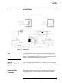
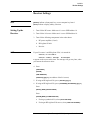

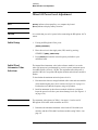
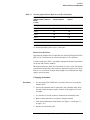
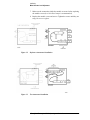
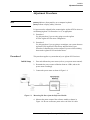
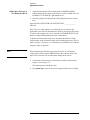
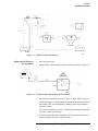
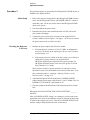

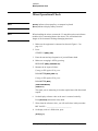
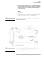
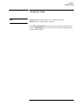
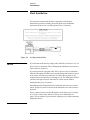
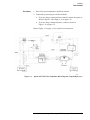
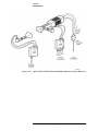


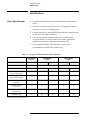

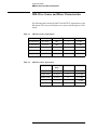

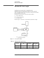
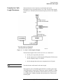


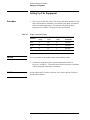

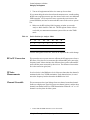


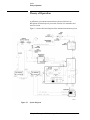


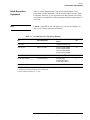

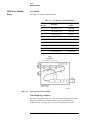
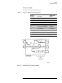

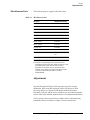


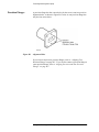
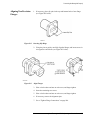


![[EN] SPARK Manual April2011](http://vs1.manualzilla.com/store/data/005899229_1-00bdd099054b23c9b74e57dfb72b875f-150x150.png)