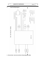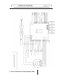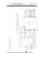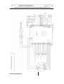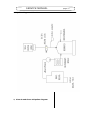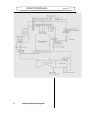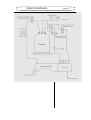
1
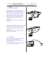
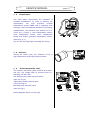
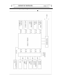
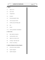
SERVICE MANUAL
Contents
1. Signal
1.1
Water level
1.2
Door state
1.3
Temperature
1.4
Pressure
1.5
Electromagnetism valve
1.6
Vacuum pump control
1.7
Heating ring & Heating pipe
1.8
Fan
1.9
Printer
1.10
Sensor parameter emendation
2. Error Code
2.1
Man-made interruption
2.2
Interrupt alarm code
2.3
Water level control error
2.4
Draining. Used water fail
2.5
Printer not working
3. Pipeline diagram & wiring diagram
3.1
Electrical principle diagram
3.2
System diagram
3.3
Pipeline diagram
page 17
SERVICE MANUAL
1. Signal
1.1
Water level inspector
A. This autoclave has a water tank inbuilt to
supply distilled water to the autoclave unit during
operation. The cycle will be affected if there is
not enough water. The autoclave has a water
level sensor that will alarm when the distilled
water is low and will send a signal to PCB as a
reminder to the user to fill water chamber to
ensure the sterilization cycle can finish
successfully.
Right figure shows the wiring of lowest water
level sensor.
B. The autoclave also has a separate tank to collect
the used water. After several cycles, the used
water tank will fill up. There is also a high level
water sensor to remind the users to drain the
used water.
You can see right figure showing the wiring of
highest water level sensor.
1.2
Door State
The chamber is an airtight body, it must afford
max. 2.4Bar pressure during the cycle.
Therefore, the door’s airtight credibility is the
most important thing.
You can see the figure on the right showing the
wiring of the door signal inspection.
page 17
SERVICE MANUAL
1.3
Temperature
The most basic requirement for autoclave is
constant temperature. In order to achieve the
requirement,
the
high
precision
PT1000
temperature sensor CMOS chip is imported from
Germany. With international advanced technology
encapsulation, the precision can achieve ±0.1°C.
There are 2 types, 3 sets temperature sensor,
inner
temperature
sensor,
outer
temperature
sensor and steam generator temperature sensor.
(See Fig a, b, c )
You can see the right figure showing the wiring.
1.4
Pressure
During the whole cycle, the chamber is full of
high temperature and high pressure steam.
1.5
Electromagnetism valve
The machine has three types solenoid valve total
five pcs. The simple data of solenoid valve is
following: DC24V 15W
Two position three way solenoid valves.
(One pcs. Fig a)
3 Normally closed solenoid valve.
(Three pcs Fig b)
Normally open solenoid valve
(One pcs Fig c)
Wiring diagram shown on the right.
page 17
SERVICE MANUAL
1.6 Vacuum pump control
The function of the vacuum pump is to vacuumize
the autoclave. Our autoclave is furnished with a
septum style vacuum pump where the max.
Pressure is 0.9Bar .It can draw out the residual
air from the equipment to reach the request of
sterilization.
(The wiring diagram of the vacuum pump, right
figure).
The control of heating ring and heating stick
The machine has adopted electric heating ring and
heating stick to heat the chamber and steam
generator. (Wiring diagram, right figure)
1.8
Fan
The steam in the chamber will become water
during the condensation phase and enter into the
used water tank after the sterilization. The fan is
the most important part of condensation it
exhausts hot steam in the condenser.
(The wiring diagram is right figure)
1.9
Printer
Runyes steam sterilizer can adopt the
prescriptive printer which tracks the record of
sterilization. Runyes steam sterilizers are only
compatible to the micro printer accompanying
this autoclave.
(The wiring diagram of printer, right figure)
page 17
SERVICE MANUAL
1.10
page 17
the data adjusting of sensor
The data of temperature and pressure must be
adjusted before leaving the factory. This phase is
accomplished by the debugging box. If the
customer needs this operation we can offer the
debugging box. (Caution: Every steam sterilizer
has been adjusted so customers needn’t debug
again to avoid the failure.)
Debugging step
1.
Turn off the power and open the door.
2.
Take off the connective wire of temperature sensor on the PCB board then
add the standard resistance.
3.
Take off the connective wire of key-press panel then connect the debugging
box.
4.
5.
Open the power switch of autoclave.
Press the debug button to enter into the revised page layout. Button “P” is
used to choose the adjust option. P means the pressure, T0 means the
temperature of sensor in the chamber, and T1 means the temperature of
steam generator’s sensor. T2 means the temperature of chamber sensor.
Referenced standard is following:
The adjusted value of pressure is between 0.00 and 0.05 (LED display should
be adjusted to 0.00)
The adjusted value of temperature should be adjusted to 130.0
6.
After the above operation, press the debug button to go back to the normal
page layout. The adjustment is over. (Note: We suggest you enter into the
revised page layout to check if the debugging has finished)
SERVICE MANUAL
page 17
2. Failure and code
2.1
Human interruption
If the user needs to exit the running of the cycle he
or she must press the START button for 3 seconds.
Caution: If you exit the sterilization cycle before
drying phase the instruments in it the chamber
have not been sterilized.
2.2
Interrupt Alarm Code
code E1:
The sensors check has automatically failed, usually there are four situations
below:
Code E1-C1: the chambers inner temperature
sensor has short circuited and cut off or the inner
temperature sensor and inspect the electric circuit
which on mainboard is failed.
Solution:
If the machine is still very hot, please allow it to cool down first
A. Use the multimeter to check the resistance data
of the inner temperature. Normally, the resistance
will be 1-2k, if not, please change the sensor
B. Turn the power off then check the magnified
chip
temperature (LT1014 or MAX479 or LMC660
or MAX478) if its hot or not. If it is hot please
replace the chip.
C. If the above inspections are normal the inner
temperature sensor does not have a problem.
SERVICE MANUAL
page 17
Code E1-C2:
The steam generator sensor short circuit, cut off or the temperature inspection
electric circuit which on mainboard is failed.
Solution:
If the machine is still very hot, please wait until it cools then start the machine.
A.
Use the multimeter to check the resistance data of the steam generator
temperature sensor. Normally, the resistance will be 1-2k, if not, please replace
the sensor.
B. Turn the power off then check the magnified chip temperature (LT1014 or
MAX479 or LMC660 or MAX478) if it’s hot or not. If it is hot please replace the
chip.
C. If the above inspections are normal the inner
temperature does not have a problem.
Code E1-C3:
The chamber outside temperature sensor short
circuit, cut off or the chamber outside temperature
inspection electric circuit which on mainboard is
failed.
Solution:
If the machine is still very hot, please wait until it cools then start the machine.
A. Use the multimeter to check the resistance data of the chamber outside
temperature sensor. Normally, the resistance will be 1-2k, if not, please change
the sensor.
B. Turn off the power then check the magnified chip temperature (LT1014 or
MAX479 or LMC660 or MAX478) if it’s hot or not. If it is hot please replace the
chip.
C. If the above inspections are normal the inner temperature does not have a
problem.
SERVICE MANUAL
page 17
SERVICE MANUAL
page 17
Code E1-C4:The pressure sensor is failed.
Solution:
A. Replace the pressure sensor
Code E2:Chamber overpressure
(The chamber pressure is above 2.4 bar for longer than 2 seconds)
Solution:
A. Please check when the pressure rises, the chamber inner temperature will also
rise up. If not or rise up very slowly, then you should check the inner temperature
sensor, please refer to E1-C1 process.
B. The chamber keep vacuum pressure, the vacuum pressure will be -0.7 bar
within 4 minutes under normally room temperature, and it will above 0.1 bar
within 5 minutes if the pressure do not leak out, otherwise, you should check the
chamber cover, solenoid valve, safety valve, vacuum pump, connector welded
points, till you find the problems where and why the pressure leak out, then solve
the problems if you find it.
C. During the machine normally working cycle, please observe if the machine
vacuum could be lower than -0.6 bar, even lower than -0.7 bar if the machine is
still cold.
D. Adjust the chamber cover and tighten a little if necessary.
E. When you run a cycle for the first time with a packed or non packed
instruments and it comes up with E2, please don’t worry. It will not come out with
the E2 alarm again when you run it the second time. When the machine leaves
the factory, the pipe which steam gets into is empty with no water inside.
SERVICE MANUAL
page 17
Code E3:the chamber overtemperature:
(the chamber temperature above 145 ℃ and the time longer than 2 seconds)
Solution:
A. if the machine is cold, please check the machine and refer to E1-C3 process,
you can find the problem as usually, and also please solve the problem.
B. If the machine is hot, please restart the machine at first, if the E3 still
continues or change as E1-C3, then please stop the machine and cool down the
machine.
C. Please start the machine when it cooled down enough, if the E3 or E1-C3 will
not stop showing, then the problem must be with the outside chamber
temperature sensor, it cuts off when the machine reaches a high temperature,
and connects again when the machine has cooled down enough. If so, you will
have to change a better outside temperature sensor.
D. If E3 comes out again when it cool down enough,
then please check the
machine refer to E1-C3 process, you can find the problem and solve it .
Code E4:constant temperature and constant pressure failed.
(the chamber pressure tolerance is greater than 0.25bar or temperature tolerance
greater than 2.5℃)
Solution:
A. please check if you can open the solenoid valve which the steam gets into.
B. please refer to E2 process.
Code E5:release the steam failed
(The steam less than 0.3bar when you release the steam longer than 20 seconds)
Solution:
A. check if you can open the steam release valve or not.
B. check if the steam release pipe has folded or not.
C. check if the two place three connections valve connected correctly or not,
including the base bottom connectors connected correctly or not.
D. check the pressure sensor on the mainboard is welded correctly.
SERVICE MANUAL
page 17
Code E6:the door will be opened automatically.
Solution:
A. Check the limit switch which inspects the door situation, usually, if you press
the limit switch, it will comes out ticktack sound, if not, you should change
another limit switch.
B. When the door is closed, you should adjust the
door if the door bolt is exceed the highest point.
Code E7:the steam generator overtemperature
(the temperature over than 230℃ and the time longer than 2 seconds)
Solution:
A. if the machine is cold, please check the machine refer to E1-C2 process, you
can find the problem and solve it.
B. If the machine is hot, please restart the machine at first, if the E7 still
continues or change as E1-C2, then please stop the machine and cool down the
machine.
C. Please start the machine when it cool down, if the E7 or E1-C2 will not comes
out ,then the problem must be the steam generator sensor, it cuts off when the
machine was in high temperature, and connects again when the machine cool
down enough. If so, you will have to change a better outside temperature sensor.
D. If E7 comes out again when it cool down enough,
then please check the
machine refer to E1-C2 process, you can find the problem and solve it .
Code E8:preheating failed
(the outside temperature sensor and steam generator temperature can not reach
at preheating data which is 55℃ and 150℃ within 30 minutes)
Solution:
A. the chamber and the steam generator are all hot, then please check the
outside temperature sensor and steam generator temperature sensor, please refer
to E1-C2 and E1-C3 process.
B. the chamber is cold, please use multimeter to check the loop of the heating
ring is good or not, usually the resistance will be 30Ω or more or less, if the loop
is cut off, then please the chamber temperature protection device is good or not,
usually it will be good, you can use multimeter to find it good or not. If it’s good,
SERVICE MANUAL
page 17
then please check the two red connection columns were connected good or not.
C. if the steam generator is cold, please check if you have revolve the
temperature adjustment device till bottom or not, then please use multiemeter to
check the loop of the heating stick is good or not, usually the resistance will be
30Ω or more or less, if there is not any resistance, then please check the two feet
of the temperature adjustment device. Usually it will be good, you can use
multimeter to find it good or not. If it’s good, but the resistance of the whole loop
is very large, then please check the three red connection columns were connected
good or not.
D. if you have finished the above three process, then you should think of to
change another mainboard.
Code E9:get into steam failed
(it can not reach at the preconcerted pressure within 30 minutes)
Solution
A. check the electromagnetism valve which the steam gets into, normally
you
can
open it, if you can’t open it, then please change another good one.
B. check the pipe which the steam gets into, it must be expedite as normally.
C. check the water level sensor to see if the there is no water, and the sensor can
not feel the water.
D. please check if you have revolved the temperature adjustment device of the
steam generator till bottom or not, if not, please revolve it till bottom.
E. check the steam generator sensor, please refer to the E1-C2。
F. check the pressure rise up or not when the steam gets into, if not, please
check the pressure sensor which refer to E1-C4 process.
G. if you have check all the above parts and still failed, then please change
another good steam generator.
SERVICE MANUAL
2.3
page 17
Warning of Water level
During the prodecure, if the distilled water tank
lacks water (water level lower than designed
lowest-location), it comes to warning.See right
figure. If it continues to warn after filled with water,
the lowest water level sensor maybe restricted or
damaged.Please check the wire-connection.You can
replace the sensor for solution.
Regarding the level sensor of used water tank,
followes the same inspect way at the highest water
level.
2.4 Failure of wastewater emission
Sometimes, wastewater can't exhaust from outinterface. Please check whether the interface is
blocked, and then remove the dirt.
2.5 Printer out of working
The printer doesn’t work after connecting well. Now
you should check the indicator on the printer if it is
light or not. If the indicator is not light this indicate
that there is no power. You must check the
connecting cable carefully. If cable is good and the
indicator is still not light please replace the printer.
If the two indicators are light the printer still
doesn’t work .You should make sure that the
printer is “on” or “off” in the options. If still won’t
do please replace a new one.
2.6 The time can’t be set up
Sometimes the time data which you have adjusted may be occur the error,
moreover the data can’t be adjusted again. At this time,you should check the
power of battery. One simple solution is that start the machine and let it in a
stand by state for several hours.This will charge the battery Then you will solve
this problem soon.
SERVICE MANUAL
3.1
Electrical principal diagram
page 17
SERVICE MANUAL
3.2
Wiring Diagram
1、
Tench wiring diagram
2、Three times vacuum autoclave wiring diagram (LED)
page 17
SERVICE MANUAL
3、Class-N autoclave wiring diagram (LED)
page 17
SERVICE MANUAL
page 17
4. Three times vacuum autoclave wiring diagram( LCD display)
SERVICE MANUAL
3.3 Pipeline Diagram
page 17
SERVICE MANUAL
1. Pipeline diagram of Tench
2、Class-B and Class-S Pipeline diagram
page 17
SERVICE MANUAL
2、
CLASS-N Pipeline diagram
page 17
SERVICE MANUAL
page 17