1
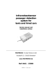
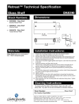
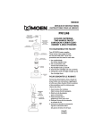
3371
ExactTemp
Service Manual
# 153768 - 5/10
©2010 Moen Incorporated • 25300 Al Moen Drive • North Olmsted, OH 44070-8022 U.S.A.
In Canada Moen Inc. • 2816 Bristol Circle • Oakville, Ontario L6H5S7
# 153768
MAINTENANCE RECORD
THERMOSTATIC MIXING VALVE
TABLE OF CONTENTS
I.
Legal/Disclaimer/Safety Warnings
pg2
II.
Valve Specifications
pg3
Valve ref.:
Location:
Installation Date:
Maintenance frequency:
Commissioning/maintenance check:
III.
Exploded Valve Diagram/Cartridge Diagram
pg4
IV.
Trouble Shooting
pg5
V.
Cartridge Calibration
pg6-8
VI.
Cartridge Servicing
1. Removal of the cartridge
2. Installation of the cartridge
VIII. Maintenance Record/Notes
TECHNICIAN
SERVICE DETAILS
pg9-10
pg11-12
VII. Stops & Checks Servicing
1. Removal of the stops and checks
2. Installation of the stops and checks
DATE
pg13
NOTES
pg13
pg14
HELPFUL TOOLS
5/8” Socket
1-1/4” Socket
Small Flat Head Screwdriver
Phillips Head Screwdriver
Channel Locks
Thermometer
Needle Nose Pliers
Safety Glasses
page 1
page 14
REPLACING STOPS & CHECKS
LEGAL/DISCLAIMER/SAFETY
NOTE: If servicing stops, water shut off valves must be shut off prior to removal.
Removal of the stops and checks:
1. Using a 5/8” socket, remove the stop by turning counterclockwise.
CAUTION — TIPS FOR REMOVAL OF OLD FAUCET: Always turn water supply
OFF before removing existing faucet or disassembling the valve. Open faucet
handle to relieve water pressure and ensure that complete water shut-off has
been accomplished.
FLUSHING
Flush supply lines prior to installation is strongly recommended to prevent
malfunction of thermostatic cartridge.
2. Using pliers, remove check valve by pulling on the check valve’s ribs.
WARNING: Risk of scalding
Varying the calibration of this thermostatic
valve to increase water temperature increases
the risk of injury from scalding. The installer is
responsible for installing the valve and any
recalibration of the water temperature in
accordance with the instructions.
Installation of the stops and checks:
1. Push the check valve into the opening.
CAUTION: Danger of scald injury. Valve
can be recalibrated to provide higher
temperature water.
2. Using a 5/8” socket, install the stop body by turning clockwise.
page 13
This valve has been preset at the factory to
provide a range of water temperatures. Any
change in settings or water inlet conditions from
those used during calibration at the factory may
raise the outlet temperature and may cause
scalding. The responsibility for the proper
installation and any recalibration of this valve
lies with the installer.
page 2
VALVE SPECIFICATIONS
Installation of the cartridge continued:
4. Using a 1-1/4” socket, install the
cartridge retaining nut in the valve.
7. Without rotating the cartridge stem,
align the temperature limit stop and the
stem.
2
1
DESCRIPTION
• Brass construction
• 3/4" IPS connections
• Thermostatic valve design with integral checkstops
OPERATION
• Temperature lever operates through a 340 degree arc with
maximum cold at full clockwise rotation and maximum hot at
full counterclockwise rotation
• Safety stop preset temperature at 105 degrees F ( 41degrees C)
• Safety stop override allows maximum temperature at 120
degrees F (49 degrees C)
• Factory established temperature range from 70 degrees F (21
degrees C) to 120 degrees F (49 degrees C)
• Must be used with at least one 3600 valve.
CARTRIDGE
• 130156 thermostatic cartridge design with
non metallic/nonferrous materials
STANDARDS
• Third party certified to ASME A112.18.1/CSA B125.1, ASSE 1016
and all applicable requirements referenced therein including
CARTRIDGE SERVICING
5. Using a wrench, install the handle
adapter nut onto the valve.
8. While pushing in the stem, install the
screw by turning clockwise until the
screw bottoms out.
6. Install spring.
1
2
9. If integrated stops were used, release
them by turning stop stem
counterclockwise until they stop.
page 3
page 12
CARTRIDGE SERVICING
EXPLODED VALVE DIAGRAM
Installation of the cartridge:
1. Verify that the cartridge is properly set by aligning the drilled hole in
the cartridge stem to the indent on the cartridge body.
1
2
3
4
5
6
2. Assemble the temperature limit stop to the cartridge ensuring that
the key on the temperature limit stop is aligned to the slot in the cartrige.
7
8
9
1.
2.
3.
4.
5.
Check Valve
6. Handle Adapter Nut
Stop Body
7. Spring
Stop Stem
8. Stem
Temperature Limit Stop
9. Screw
Cartridge Nut
For service kit numbers refer to moen.com
3. By pushing on the front of the temperature limit stop, insert cartridge into
the valve body until the temperature limit stop key is fully seated into the valve.
CARTRIDGE DIAGRAM
1
2
3
5
4
1.
2.
3.
4.
page 11
Bottom O-Ring
Middle O-Ring
Top O-Ring
Screens
5. Pre-Set Temperature Alignment
Markings (105˚)
page 4
Problem
Description
Cause
CARTRIDGE SERVICING
Fix
Reduced flow or
no flow from device
Stop stems are closed
Turn stop stems
counterclockwise
No flow or reduced flow
Reduced flow or
no flow from device
Blocked screens on
cartridge
Remove cartridge and
rinse. See “Cartridge
Servicing” (pg 9).
Outlet water
temperature too high
Water is hotter than
105˚F at safety stop or
120˚F in full hot
Cartridge is out of
calibration
Remove cartridge and
rinse. See “Cartridge
Calibration” (pg 7).
1
No flow or reduced flow
Removal of cartridge continued:
5. Using a 1-1/4” socket, remove the cartridge retaining nut by turning
counterclockwise.
2
TROUBLE SHOOTING
6. Remove temperature limit stop.
Outlet water
temperature too high
Water is hotter than
105˚F at safety stop or
120˚F in full hot
Missing or damaged
bottom o-ring
Replace cartridge.
See “Cartridge
Servicing” (pg 9).
Leak from around the
cartridge
Continuous leak from
behind trim
Cartridge has missing
or damaged top
o-ring.
Replace cartridge.
See “Cartridge
Servicing” (pg 9).
Leak from around the
cartridge
Continuous leak from
behind trim
Missing or loose
cartridge nut
Replace or tighten
cartridge nut.
See “Cartridge
Servicing” (pg 9).
All hot or all cold water
Temperature
adjustment does not
provide mixed
temperature
Inlets are reversed
No temperature stop
detected
Handle rotates greater
than 200˚ and does
not engage a stop
Temperature limit stop
is not properly seated
in the valve
page 5
Reinstall with hot water
line to hot side of the
valve and cold water
line to cold side of the
valve.
7. Remove cartridge by using a wrench to pull out the cartridge.
Reassemble
temperature limit stop.
See “Cartridge
Servicing” (pg 9).
page 10
CARTRIDGE CALIBRATION
CARTRIDGE SERVICING
Removal of cartridge:
1. If water supply shut off valves are not accessible or are not present, actuate the
stops by rotating the stop stem clockwise. Do not over tighten stop stem as this
could damage the check valve. (fig.1)
2. While holding the stem to prevent rotation, remove the screw turning
counterclockwise. (fig.2)
Rotate the temperature control counterclockwise from the coolest setting (80˚ F) at
the 7:00 position to the safety stop setting (105˚ F) at the 12:00 position.
Push in the end of the stem to activate the safety stop override, then rotate the
stem counterclockwise from (105˚ F) at the 12:00 position to the maximum
temperature (120˚ F) at the 9:00 position. (fig.1)
Use a thermometer to test the temperature of the water. If it is 120˚ F or less, turn
the water off and attach your trim. No calibration is necessary.
3. Remove spring. (fig.3)
4. Using a wrench, remove the handle adapter nut by turning counterclockwise.
(fig.4)
1
Temperature Valve
12
Turn
7
1
12
Push, Hold, and Turn
9
1
2
fig.1
3
fig.2
2
fig.1
If the temperature is higher than 120˚ F, the valve must be calibrated to a lower
temperature. To lower the maximum temperature, proceed to step 2 on page 7.
fig.3
fig.4
page 9
page 6
CARTRIDGE CALIBRATION
CARTRIDGE CALIBRATION
cont.
cont.
2
C4
Temperature Valve
Rotate the temperature stem from the hottest
position (9:00) clockwise to the safety stop
position position (12:00). This is 1/4 of a turn
and the stem will pop out when the proper
position is reached.
12
Rotate the stem from the (2:00) position
counterclockwise to the (12:00) position.(fig.4)
12
9
1
2
Continue rotating the stem clockwise from the
(12:00) position to the (2:00) position. (fig.2)
12
2
3
fig.4
fig.2
5
3
Replace the stem in the new position and
secure with screw. (fig.5)
Disengage Splines
While holding the stem to prevent rotation,
remove the screw turning counterclockwise.
Pull the stem from the valve without rotating.
(fig.3)
2
1
1
fig.5
2
fig.3
Test the temperature of the water. If it is still over 120˚ F, repeat
steps 3 and 4 to lower the maximum temperature.
page 7
page 8
2
CARTRIDGE CALIBRATION
CARTRIDGE CALIBRATION
cont.
cont.
2
C4
Temperature Valve
Rotate the temperature stem from the hottest
position (9:00) clockwise to the safety stop
position position (12:00). This is 1/4 of a turn
and the stem will pop out when the proper
position is reached.
12
Rotate the stem from the (2:00) position
counterclockwise to the (12:00) position.(fig.4)
12
9
1
2
Continue rotating the stem clockwise from the
(12:00) position to the (2:00) position. (fig.2)
12
2
3
fig.4
fig.2
5
3
Replace the stem in the new position and
secure with screw. (fig.5)
Disengage Splines
While holding the stem to prevent rotation,
remove the screw turning counterclockwise.
Pull the stem from the valve without rotating.
(fig.3)
2
1
1
fig.5
2
fig.3
Test the temperature of the water. If it is still over 120˚ F, repeat
steps 3 and 4 to lower the maximum temperature.
page 7
page 8
2
CARTRIDGE CALIBRATION
CARTRIDGE SERVICING
Removal of cartridge:
1. If water supply shut off valves are not accessible or are not present, actuate the
stops by rotating the stop stem clockwise. Do not over tighten stop stem as this
could damage the check valve. (fig.1)
2. While holding the stem to prevent rotation, remove the screw turning
counterclockwise. (fig.2)
Rotate the temperature control counterclockwise from the coolest setting (80˚ F) at
the 7:00 position to the safety stop setting (105˚ F) at the 12:00 position.
Push in the end of the stem to activate the safety stop override, then rotate the
stem counterclockwise from (105˚ F) at the 12:00 position to the maximum
temperature (120˚ F) at the 9:00 position. (fig.1)
Use a thermometer to test the temperature of the water. If it is 120˚ F or less, turn
the water off and attach your trim. No calibration is necessary.
3. Remove spring. (fig.3)
4. Using a wrench, remove the handle adapter nut by turning counterclockwise.
(fig.4)
1
Temperature Valve
12
Turn
7
1
12
Push, Hold, and Turn
9
1
2
fig.1
3
fig.2
2
fig.1
If the temperature is higher than 120˚ F, the valve must be calibrated to a lower
temperature. To lower the maximum temperature, proceed to step 2 on page 7.
fig.3
fig.4
page 9
page 6
Problem
Description
Cause
CARTRIDGE SERVICING
Fix
Reduced flow or
no flow from device
Stop stems are closed
Turn stop stems
counterclockwise
No flow or reduced flow
Reduced flow or
no flow from device
Blocked screens on
cartridge
Remove cartridge and
rinse. See “Cartridge
Servicing” (pg 9).
Outlet water
temperature too high
Water is hotter than
105˚F at safety stop or
120˚F in full hot
Cartridge is out of
calibration
Remove cartridge and
rinse. See “Cartridge
Calibration” (pg 7).
1
No flow or reduced flow
Removal of cartridge continued:
5. Using a 1-1/4” socket, remove the cartridge retaining nut by turning
counterclockwise.
2
TROUBLE SHOOTING
6. Remove temperature limit stop.
Outlet water
temperature too high
Water is hotter than
105˚F at safety stop or
120˚F in full hot
Missing or damaged
bottom o-ring
Replace cartridge.
See “Cartridge
Servicing” (pg 9).
Leak from around the
cartridge
Continuous leak from
behind trim
Cartridge has missing
or damaged top
o-ring.
Replace cartridge.
See “Cartridge
Servicing” (pg 9).
Leak from around the
cartridge
Continuous leak from
behind trim
Missing or loose
cartridge nut
Replace or tighten
cartridge nut.
See “Cartridge
Servicing” (pg 9).
All hot or all cold water
Temperature
adjustment does not
provide mixed
temperature
Inlets are reversed
No temperature stop
detected
Handle rotates greater
than 200˚ and does
not engage a stop
Temperature limit stop
is not properly seated
in the valve
page 5
Reinstall with hot water
line to hot side of the
valve and cold water
line to cold side of the
valve.
7. Remove cartridge by using a wrench to pull out the cartridge.
Reassemble
temperature limit stop.
See “Cartridge
Servicing” (pg 9).
page 10
CARTRIDGE SERVICING
EXPLODED VALVE DIAGRAM
Installation of the cartridge:
1. Verify that the cartridge is properly set by aligning the drilled hole in
the cartridge stem to the indent on the cartridge body.
1
2
3
4
5
6
2. Assemble the temperature limit stop to the cartridge ensuring that
the key on the temperature limit stop is aligned to the slot in the cartrige.
7
8
9
1.
2.
3.
4.
5.
Check Valve
6. Handle Adapter Nut
Stop Body
7. Spring
Stop Stem
8. Stem
Temperature Limit Stop
9. Screw
Cartridge Nut
For service kit numbers refer to moen.com
3. By pushing on the front of the temperature limit stop, insert cartridge into
the valve body until the temperature limit stop key is fully seated into the valve.
CARTRIDGE DIAGRAM
1
2
3
5
4
1.
2.
3.
4.
page 11
Bottom O-Ring
Middle O-Ring
Top O-Ring
Screens
5. Pre-Set Temperature Alignment
Markings (105˚)
page 4
VALVE SPECIFICATIONS
Installation of the cartridge continued:
4. Using a 1-1/4” socket, install the
cartridge retaining nut in the valve.
7. Without rotating the cartridge stem,
align the temperature limit stop and the
stem.
2
1
DESCRIPTION
• Brass construction
• 3/4" IPS connections
• Thermostatic valve design with integral checkstops
OPERATION
• Temperature lever operates through a 340 degree arc with
maximum cold at full clockwise rotation and maximum hot at
full counterclockwise rotation
• Safety stop preset temperature at 105 degrees F ( 41degrees C)
• Safety stop override allows maximum temperature at 120
degrees F (49 degrees C)
• Factory established temperature range from 70 degrees F (21
degrees C) to 120 degrees F (49 degrees C)
• Must be used with at least one 3600 valve.
CARTRIDGE
• 130156 thermostatic cartridge design with
non metallic/nonferrous materials
STANDARDS
• Third party certified to ASME A112.18.1/CSA B125.1, ASSE 1016
and all applicable requirements referenced therein including
CARTRIDGE SERVICING
5. Using a wrench, install the handle
adapter nut onto the valve.
8. While pushing in the stem, install the
screw by turning clockwise until the
screw bottoms out.
6. Install spring.
1
2
9. If integrated stops were used, release
them by turning stop stem
counterclockwise until they stop.
page 3
page 12
REPLACING STOPS & CHECKS
LEGAL/DISCLAIMER/SAFETY
NOTE: If servicing stops, water shut off valves must be shut off prior to removal.
Removal of the stops and checks:
1. Using a 5/8” socket, remove the stop by turning counterclockwise.
CAUTION — TIPS FOR REMOVAL OF OLD FAUCET: Always turn water supply
OFF before removing existing faucet or disassembling the valve. Open faucet
handle to relieve water pressure and ensure that complete water shut-off has
been accomplished.
FLUSHING
Flush supply lines prior to installation is strongly recommended to prevent
malfunction of thermostatic cartridge.
2. Using pliers, remove check valve by pulling on the check valve’s ribs.
WARNING: Risk of scalding
Varying the calibration of this thermostatic
valve to increase water temperature increases
the risk of injury from scalding. The installer is
responsible for installing the valve and any
recalibration of the water temperature in
accordance with the instructions.
Installation of the stops and checks:
1. Push the check valve into the opening.
CAUTION: Danger of scald injury. Valve
can be recalibrated to provide higher
temperature water.
2. Using a 5/8” socket, install the stop body by turning clockwise.
page 13
This valve has been preset at the factory to
provide a range of water temperatures. Any
change in settings or water inlet conditions from
those used during calibration at the factory may
raise the outlet temperature and may cause
scalding. The responsibility for the proper
installation and any recalibration of this valve
lies with the installer.
page 2
MAINTENANCE RECORD
THERMOSTATIC MIXING VALVE
TABLE OF CONTENTS
I.
Legal/Disclaimer/Safety Warnings
pg2
II.
Valve Specifications
pg3
Valve ref.:
Location:
Installation Date:
Maintenance frequency:
Commissioning/maintenance check:
III.
Exploded Valve Diagram/Cartridge Diagram
pg4
IV.
Trouble Shooting
pg5
V.
Cartridge Calibration
pg6-8
VI.
Cartridge Servicing
1. Removal of the cartridge
2. Installation of the cartridge
VIII. Maintenance Record/Notes
TECHNICIAN
SERVICE DETAILS
pg9-10
pg11-12
VII. Stops & Checks Servicing
1. Removal of the stops and checks
2. Installation of the stops and checks
DATE
pg13
NOTES
pg13
pg14
HELPFUL TOOLS
5/8” Socket
1-1/4” Socket
Small Flat Head Screwdriver
Phillips Head Screwdriver
Channel Locks
Thermometer
Needle Nose Pliers
Safety Glasses
page 1
page 14
3371
ExactTemp
Service Manual
# 153768 - 5/10
©2010 Moen Incorporated • 25300 Al Moen Drive • North Olmsted, OH 44070-8022 U.S.A.
In Canada Moen Inc. • 2816 Bristol Circle • Oakville, Ontario L6H5S7
# 153768