1
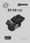
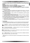
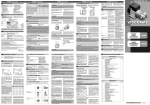
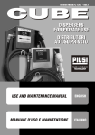
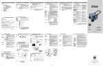
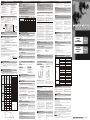
ENGLISH (Translated from Italian)
A
A
B
C
D
E
F
G
H
ENGLISH (Translated from Italian)
INDEX
Index
Machine and Manufacturer Identification
Declar. of Incorporation of partly-completed Machinery
Machine Description
Technical Specifications
E1 Performance Specifications
E2 Electrical Specifications
Operating Conditions
F1 Environmental Conditions
F2 Electrical Power Supply
F3 Working Cycle
F4 Fluids Permitted / Fluids Not Permitted
Moving and Transport
Installation
H1 Disposing of the Packing Material
B
H2
H3
H4
H5
I
L
M
N
O
P
Q
R
Preliminary Inspection
Positioning the Pump
Connecting the Tubing
Considerations Regarding
Delivery and Suction Lines
H6 Line Accessories
H7 Electrical Connections
Initial Start-Up
Daily Use
Problems and Solutions
Maintenance
Noise Level
Disposal
Exploded Diagrams and Spare Parts
Dimensions and Weights
! ATTENTION
The curve refers to the following operating conditions:
! ATTENTION
It is the installer's responsibility to use tubing with adequate characteristics.
Fluid:
Temperature:
Suction Conditions:
The use of tubing unsuitable for use with Diesel fuel can damage the pump, injure
persons and cause pollution.
•
Do not operate switches with wet hands.
•
Prolonged contact with diesel fuel can
Diesel Fuel
20°C
The tube and the pump position relative to the fluid level is such
that a pressure of 0.3 bar is generated at the nominal flow rate.
ELECTRICAL SPECIFICATIONS
ELECTRICAL POWER
MANUFACTURER:
PIUSI SPA - VIA PACINOTTI - Z.I. RANGAVINO
46029 SUZZARA (MN)
IDENTIFICATION PLATE (EXAMPLE WITH THE FIELDS IDENTIFIED):
PRODUCT
CODE
PRODUCTION
YEAR
MODEL
TECHNICAL
DATA
MANUAL
MODEL PUMP
The undersigned:
PIUSI S.p.A - Via Pacinotti c.m. - z.i.Rangavino
46029 Suzzara (Mantova) - Italy
Frequency
(Hz)
PANTHER 56 230V/50HZ
AC
230
50
370
2.2
PANTHER 56 230V/60HZ
AC
230
60
370
2.2
PANTHER 72 230V/50HZ
AC
230
50
550
3.3
PANTHER 56 400V/50HZ
AC
400
50
370
0.9
PANTHER 56 400V/60HZ
AC
400
60
370
0.9
PANTHER 72 400V/50HZ
AC
400
50
550
1.3
AC
110
50
500
5.5
PANTHER 56 110V/60HZ
AC
110
60
700
7.5
PANTHER 56 100V/50HZ
AC
100
50
550
6.5
PANTHER 56 100V/60HZ
AC
100
60
600
7.8
(*)
OPERATING CONDITIONS
ENVIRONMENTAL CONDITIONS
TEMPERATURE:
min. -20°C / max. +60°C
RELATIVE HUMIDITY:
max. 90%
! ATTENTION
The temperature limits shown apply to the pump components and must be respected to
avoid possible damage or malfunction.
F2
Tighten the connections, if necessary.
F3
WORKING CYCLE
by-pass with the consequent noticeable
reduction of the flow rate supplied.
The combination of the length of the tubing,
the diameter of the tubing, the flow rate of
the diesel fuel and the line accessories
installed can create back pressure greater
than the maximums anticipated such as
to cause the (partial) opening of the pump
In such cases, to allow correct functioning of
the pump, it is necessary to reduce system
resistance, using shorter tubing and/or of
wider diameter and line accessories with less
resistance (e.g. , an automatic dispensing
nozzle for greater flow rates).
SUCTION
During the start-up phase, with an empty
suction tube and the pump wetted with fluid,
the electric pump unit is capable of suctioning
the liquid with a maximum difference in height
of 2 meters. It is important to point out that the
priming time can be as long as one minute and
the presence of an automatic dispensing
nozzle on the delivery line prevents the
evacuation of air from the installation, and,
therefore, prevents proper priming.
For this reason, it is always advisable to prime the
pump without an automatic delivery nozzle,
verifying the proper wetting of the pump. The
installation of a foot valve is recommended to
prevent the emptying of the suction tube and
keep the pump wet. In this way, the pump will
subsequently always start up immediately.
When the system is functioning, the pump can
work with pressure at the inlet as high as 0.5
bar, beyond which cavitation phenomena can
begin, with a consequent loss of flow rate and
increase of system noise.
As we have said up to this point, it is important
to guarantee low suction pressure by using
short tubing of a diameter equal to or larger
than recommended, reducing curves to a
minimum and using suction filters of wide
cross-section and foot valves with the lowest
possible resistance.
It is very important to keep the suction filters
clean because, once clogged, they increase
system resistance.
The difference in height between the pump
and the fluid level must be kept as small as
possible and, at any rate, within the 2 meters
anticipated for the priming phase.
If this height is exceeded, it will always be
necessary to install a foot valve to allow for the
filling of the suction tube and provide tubing of
wider diameter. It is recommended that the
pump not be installed at a difference in height
greater than 3 meters.
! ATTENTION
In the case that the suction tank is higher than the pump, it is advisable to install an
antisiphon valve to prevent accidental diesel fuel leaks.
Dimension the installation in order to control the back pressures due to water
hammering.
H6
In the priming phase the pump must blow the
air initially present in the entire installation out
of the delivery line.
•
•
That the pump is not running completely
dry;
That the suction tubing is not allowing air
to seep in;
That the suction filter is not clogged;
F4
Self-Priming, volumetric, rotating electric vane pump, equipped with by-pass valve.
MOTOR:
Asynchronous motor, single-phase and three-phase, 2 pole, closed type (protection
class IP55 in conformance with EN 60034-5-86 regulations) self-ventilated, directly
flanged to the pump body.
FILTER:
Inspectable suction filter.
TECHNICAL SPECIFICATIONS
E1
PERFORMANCE SPECIFICATIONS
When priming has occurred, verify that the pump is operating within the anticipated range, in
particular:
•
•
That under conditions of maximum back
pressure, the power absorption of the
motor stays within the values shown on
the identification plate;
NOT PERMITTED:
GASOLINE
INFLAMMABLE LIQUIDS with PM < 55°C
LIQUIDS WITH VISCOSITY > 20 cSt
WATER
FOOD LIQUIDS
CORROSIVE CHEMICAL PRODUCTS
• SOLVENTS
L
(Maximum
Flow Rate)
B
(Maximum
Back
Pressure)
C
(Bypass)
Panther 56
60
0.6
Panther 72
80
0.5
PA80 Automatic
Dispensing Nozzle
PA60 Automatic
Dispensing Nozzle
Self2000 Manual
Dispensing Nozzle
K33/K44 Meter
4 meters of 1” tube
4 meters of 3/4” tube
Back
Pressure
LINE ACCESSORIES
line accessories whose use is compatible with
the proper functioning of the pumps.
DELIVERY
Automatic dispensing nozzle
Manual dispensing nozzle
Meter
Flexible tubing
SUCTION
Foot valve with filter
Rigid and flexible tubing
b. Before starting the pump make sure that
the delivery valve is closed (dispensing
nozzle or line valve).
! ATTENTION
It is the installer's responsibility to provide the line accessories necessary for the safe
and proper functioning of the pump.
The use of accessories unsuitable for use with diesel fuel can damage the pump, injure
persons and cause pollution.
H7
RELATED DANGERS:
FIRE - EXPLOSION
FIRE - EXPLOSION
MOTOR OVERLOAD
PUMP OXIDATION
CONTAMINATION OF THE SAME
PUMP CORROSION
INJURY TO PERSONS
• FIRE - EXPLOSION
DAMAGE TO GASKET SEALS
Given the limited weight and size of the
pumps (see overall dimensions), moving the
pumps does not require the use of lifting
devices.
To change the cable, open the terminal strip
cover and connect the line according to the
following diagram:
THREE PHASE
A.C. LINE
H
H1
DISPOSING OF THE PACKING MATERIAL
45
0.5
•
Check that the machine has not suffered
any damage during transport or storage.
•
Panther 56
100/110-60Hz
Make sure that the motor shaft turns
freely.
54
0.5
•
•
Panther 56
56
1.5
Clean the inlet and outlet openings,
removing any dust or residual packing
material.
Check that the electrical specifications
correspond to those shown on the
identification plate.
Panther 72
72
1.3
Panther 56
60 Hz
98
1.4
Panther 56
100/110-50Hz
42
1.4
Panther 56
100/110-60Hz
50
1.4
Panther 56
0
2.7
Panther 72
0
2.8
Panther 56
60 Hz
0
2.8
Panther 56
100/110-50Hz
0
2.7
Panther 56
100/110-60Hz
0
2.8
H2
H3
•
•
Delivery Closed
•
•
PRELIMINARY INSPECTION
TO
MOTOR
model.
The characteristics of the capacitor are shown
on the identification plate for each pump
The switch has the sole function of starting/
stopping the pump and cannot in any way
substitute for the main circuit breaker
provided for in the applicable regulations.
THREE-PHASE MOTORS
Three-phase motors are supplied with a
terminal strip box and terminal strip.
To connect the electric motor to the electric
power line, open the terminal strip cover
and connect the cables according to the
diagram.
In either case, act as follows:
a. Close the delivery valve
b. Attach the end of the delivery to the slot provided on the tank
c. Turn the ON/OFF switch to the OFF position.
M
The pump can be installed in any position
(pump axis vertical or horizontal)
Attach the pump using screws of
adequate diameter for the attachment
The pumps are supplied without electrical safety equipment such as fuses, motor
protectors, systems to prevent accidental restarting after power failures or others.
It is indispensable to install an electric panel, upstream from the pump's power
supply line, equipped with an appropriate residual current operated circuit
breaker.
holes provided in the base of the pump
(see the section "OVERALL
DIMENSIONS" for their position and
dimension).
It is the installer's responsibility to perform the electrical connections with respect for
the applicable regulations.
! ATTENTION
THE MOTORS ARE NOT OF AN ANTI-EXPLOSIVE TYPE.
Do not install them where inflammable vapors can be present.
Respect the following (not exhaustive) instructions to ensure a proper electrical
installation:
H4
•
CONNECTING THE TUBING
Before connection, make sure that the
tubing and the suction tank are free of dirt
and thread residue that could damage the
pump and its accessories.
Before connecting the delivery tube,
•
partially fill the pump body with diesel fuel
to facilitate priming.
•
Do not use conical threaded joints that
could damage the threaded pump
openings if excessively tightened.
•
I
SUCTION TUBING:
DELIVERY TUBING:
- Minimum recommended nominal diameter:
- Nominal recommended pressure:
During installation and maintenance,
make sure that the electric supply lines
are not live.
Use cables characterized by the minimum
cross-sections, nominal voltages and
wiring-type adequate to the characteristics shown in Paragraph E2 ELECTRICAL
SPECIFICATIONS and the installation
environment.
In three-phase motors verify the correct
1”
10 bar
•
•
direction of rotation (see Paragraph R DIMENSIONS AND WEIGHTS)
All motors are equipped with a ground
terminal to connect to the ground line of
the electrical network.
Always close the cover of the terminal
strip box before supplying electrical
power, after ascertaining the integrity of
the gasket seals that ensure protection
grade IP 55.
INITIAL START-UP
•
Check that the quantity of diesel fuel in the
suction tank is greater than the amount
you wish to transfer.
•
Make sure that the residual capacity of the
delivery tank is greater than the quantity
you wish to transfer.
MANUALE
D’USO E
MANUTENZIONE
ITALIANO
USE AND
MAINTENANCE
MANUAL
ENGLISH
PROBLEMS AND SOLUTIONS
Problem
THE MOTOR TURNS
SLOWLY WHEN
STARTING
Possible Cause
Rotor jammed
The motor protecting thermal
switch has tripped
Wait for the motor to cool, verify that
it restarts, and research the cause
of the overheating
Motor problems
Contact the Service Department
Low voltage in the electric power
line
Bring the voltage back within the
anticipated limits
Low level in the suction tank
Refill the tank
Foot valve blocked
Clean and/or replace the valve
Filter clogged
Clean the filter
Excessive suction pressure
Lower the pump with respect to the
level of the tank or increase the
cross-section of the tubing
High loss of head in the circuit
(working with the by-pass open)
Use shorter tubing or of greater
diameter
By-pass valve blocked
Dismantle the valve, clean and/or
replace it
Air entering the pump or the
suction tubing
Check the seals of the connections
Low rotation speed
INCREASED PUMP
NOISE
LEAKAGE FROM THE
PUMP BODY
•
Do not run the pump dry. This can cause
serious damage to its components.
•
Make sure that the tubing and line
accessories are in good condition. Diesel
fuel leaks can damage objects and injure
persons.
Correttive Action
Check the electrical connections and
the safety systems
Check for possible damage or obstruction of the rotating components
A narrowing in the suction tubing
N
! ATTENTION
Verify that the terminal strip blades are positioned according to the diagram provided for
the available power supply voltage. Verify the correct direction of rotation of the motor
(see the paragraph overall dimensions), and, if not correct, invert the connection of the
two cables in the power supply plug or on the terminal strip.
POSITIONING THE PUMP
- Minimum recommended nominal diameter: 1-1/4”
- Nominal recommended pressure:
10 bar
- Use tubing suitable for functioning under suction pressure
Back Pressure
When dispensing is finished, turn off the
pump.
- A safety device tripping
- A drop in line voltage
LOW OR NO
FLOW RATE
any way dangerous or polluting.
Refer to local regulations for its disposal.
0.5
0
f.
LACK OF ELECTRIC POWER:
TO MOTOR
Single-phase motors are supplied with a bipolar switch and capacitor wired and installed
inside the terminal strip box (see diagram).
INSTALLATION
75
C
e. Close the delivery valve to stop
dispensing.
! ATTENTION
Functioning with the delivery closed is only allowed for brief periods (2-3 minutes
maximum). After use, make sure the pump is turned off.
SINGLE PHASE
The pumps were carefully packed before
shipment.
Check the packing material on delivery and
store in a dry place.
Panther 56
100/110-50Hz
B
d. Open the delivery valve, solidly grasping
the end of the tubing.
c. Turn the ON/OFF switch to ON. The by-
ELECTRICAL CONNECTIONS
SINGLE-PHASE MOTORS
Single-phase motors are supplied with a
pre-existing 2-meter cable with electric plug.
•
•
•
•
•
•
Panther 56
60 Hz
A
pass valve allows functioning with the
delivery closed for only brief periods.
Resume operations as described in Paragraph L - DAILY USE, after determining the cause of
the stoppage.
MOVING AND TRANSPORT
The packing material does not require special
precautions for its disposal, not being in
Flow Rate
A
Flow
Rate
That the back pressure in the delivery line
is not greater than the maximum back
pressure anticipated for the pump.
DAILY USE
a. If using flexible tubing, attach the ends of
the tubing to the tanks. In the absence of an
appropriate slot, solidly grasp the delivery
tube before beginning dispensing.
CONDENSER
G
Typical Delivery Configuration
Model
than 0.5 bar;
•
That the suction pressure is not greater
The performance diagram shows flow rate as a function of back pressure.
Functioning
Point
•
That the suction height is not greater than
2 meters (if the height is greater than 2
meters, fill the suction tube with fluid);
That the delivery tube is allowing the
evacuation of the air.
A lack of electric power, with the consequent accidental stopping of the pump, can be
caused by:
The pumps are furnished without line accessories. Following is a list of the most common
FLUIDS PERMITTED / FLUIDS NOT PERMITTED
PERMITTED:
• DIESEL FUEL at a viscosity of from 2 to 5.35 cSt (at a temperature of 37.8°C)
Minimum Flash Point (PM): 55°C
•
•
•
•
•
•
E
•
Lack of electric power
MACHINE DESCRIPTION
PUMP:
Therefore it is necessary to keep the outlet
open to permit the evacuation of the air.
The priming phase can last from several seconds to a few minutes, as a function of the
characteristics of the system. If this phase is prolonged, stop the pump and verify:
THE MOTOR IS NOT
TURNING
D
Single-phase motors are provided with an
automatic thermal protection switch.
! ATTENTION
If an automatic type dispensing nozzle is installed on the end of the delivery line, the
evacuation of the air will be difficult because of the automatic stopping device that keeps
the valve closed when the line pressure is too low. It is recommended that the automatic
dispensing nozzle be temporarily disconnected during the initial start-up phase.
•
Panther 56 and Panther 72 pumps are self-priming
and characterized by good suction capacity.
! ATTENTION
Functioning under by-pass conditions is only allowed for brief periods of time (2-3
minutes maximum).
the legal representative
CONSIDERATIONS REGARDING DELIVERY AND SUCTION LINES
The choice of pump model must be made keeping
the characteristics of the system in mind.
The pumps are designed for continuous use under conditions of maximum back pressure.
Suzzara, 29/12/2009
•
Bulletin
M0042C
IT/EN
Rev. 1
The thermal protection automatically turns off when the motor is sufficiently cool.
H5
The maximum acceptable variations from the
electrical parameters are:
Voltage:
+/- 5% of the nominal value
Frequency: +/- 2% of the nominal value
! ATTENTION
Power from lines with values outside the indicated limits can damage the electrical
components.
damage the skin. The use of glasses and
gloves is recommended.
Turn off the pump and wait for it to cool before resuming use.
ELECTRICAL POWER SUPPLY
Depending on the model, the pump must be
supplied by a single-phase alternating current line
whose nominal values are shown in the table in
Paragraph E2 - ELECTRICAL SPECIFICATIONS.
is in conformity with the legal provisions indicated in the directives:
- Machine Directive 2006/42/EC
- Low-Voltage Directive 2006/95/EC
- Electromagnetic Compatibility Directive 2004/108/EC
To which the essential safety requirements have been applied and complied with what indicated on
annex I of the machine directive applicable to the product and shown below: 1.1.3 - 1.1.5 - 1.3.1 1.3.2 - 1.3.3 - 1.3.4 - 1.3.8 - 1.4.1 - 1.4.2.1 - 1.5.1 - 1.5.2 - 1.5.4 - 1.5.5 - 1.5.8 - 1.5.11 - 1.6.1 - 1.6.3 1.6.4 - 1.7.1 - 1.7.2 - 1.7.3 - 1.7.4.
The documentation is at the disposal of the competent authority following motivated request at Piusi
S.p.A. or following request sent to the email address: doc_tec@piusi.com
The person authorised to compile the technical file and
draw up the declaration is Otto Varini as legal representative.
(*)
refers to functioning with maximum back pressure
F
Machine designed for the transfer of diesel fuel
PANTHER 56 / PANTHER 72
refer to Lot Number shown on CE plate affixed to product
refer to the year of production shown on the CE plate affixed to the
product
is intended to be incorporated in a machine (or to be with other machines) so as to create a
machine to which applies Machine Directive 2006/42/EC, may not be brought into service before
the machine into which it is to be incorporated has been declared in conformity with the provisions
of the directive 2006/42/EC.
(*)
PANTHER 56 110V/50HZ
HEREBY STATES under its own responsibility, that the partly-completed machinery:
Description:
Model:
Serial number:
Year of manufacture:
Maximum
(Amp)
Voltage
(V)
F1
DECLARATION OF INCORPORATION OF PARTLY-COMPLETED MACHINERY
Nominal
(Watt)
CURRENT
Current
! ATTENTION
Always check that the revision level of this manual coincides with what is shown on the
identification plate.
C
POWER
Never start or stop the pump by inserting
or removing any plugs.
! ATTENTION
Extreme operating conditions can raise the motor temperature and, consequently,
cause the thermal protection switch to stop it.
Check all the connections after the initial installation and on a daily basis after that.
DELIVERY
The burst pressure of the pump is of 20 bar.
E2
• PANTHER 72 230V/50HZ
• PANTHER 72 400V/50HZ
Loosening of the connections (threaded connections, flanging, gasket seals) can cause
serious ecological and safety problems.
To obtain the best performance, it is very important to reduce loss of suction pressure as
much as possible by following these instructions:
• Shorten the suction tube as much as possible
• Avoid useless elbows or throttling in the tubes
• Keep the suction filter clean
• Use a tube with a diameter equal to, or greater than, indicated (see Installation)
Available Models:
• PANTHER 56 400V/50HZ
• PANTHER 56 400V/60HZ
ENGLISH (Translated from Italian)
•
Under different suction conditions higher pressure values can be created that reduce
the flow rate compared to the same back pressure values.
MACHINE AND MANUFACTURER IDENTIFCATION
• PANTHER 56 230V/50HZ
• PANTHER 56 230V/60HZ
ENGLISH (Translated from Italian)
Use tubing suitable for working
under suction pressure
Check the voltage at the pump.
Adjust the voltage and/or use cables
of greater cross-section
The suction tubing is resting on
the bottom of the tank
Raise the tubing
Cavitation occurring
Reduce suction pressure
until the air is purged from
Irregular functioning of the by-pass Dispense
the circuit
Air present in the diesel fuel
Verify the suction connections
Seal damaged
Check and replace the mechanical
seal
MAINTENANCE
Panther 56 and Panther 72 pumps are designed and constructed to require a minimum of
maintenance.
• On a weekly basis, check that the tubing
• On a monthly basis, check and keep the
joints have not loosened, to avoid any
pump filter clean and any other filters
leakage.
installed.
• On a monthly basis, check the pump body
• On a monthly basis, check that the electric
and keep it clean of any impurities.
power supply cables are in good condition.
O
NOISE LEVEL
Under normal working conditions the noise
emission from all models does not exceed the
P
value of 70 db at a distance of 1 meter from
the electric pump.
DISPOSAL
The components must be given to companies that specialise in the disposal and recycling of
industrial waste and, in particular, the:
DISPOSAL OF PACKAGING:
The packaging consists of biodegradable cardboard which can be delivered to companies for
normal recycling of cellulose.
DISPOSAL OF METAL COMPONENTS:
The metal components, both painted and stainless steel, are usually recycled by companies that
are specialised in the metal-scrapping industry.
DISPOSAL OF ELECTRIC AND ELECTRONIC COMPONENTS:
these have to be disposed by companies that are specialised in the disposal of electronic
components, in accordance with the instructions of 2002/96/EC (see text of Directive below).
ENVIRONMENTAL INFORMATION FOR CUSTOMERS IN THE EUROPEAN UNION:
European Directive 2002/96/EC requires that the equipement bearing this symbol
on the product and/or its packaging must not be disposed of with unsorted
municipal waste. The symbol indicates that this product should be disposed of
separately from regular household waste streams.
It is your responsibility to dispose of this and other electric and electronic
equipment via designated collection facilities appointed by the government or
local authorities.
DISPOSAL OF OTHER PARTS:
The disposal of other parts such as pipes, rubber seals, plastic components and cables should be
entrusted to companies that special in the disposal of industrial waste.
Bulletin M0042C IT/EN - Rev.1
Copyright
ITALIANO (Lingua Originale)
A
A
B
C
D
E
F
G
H
ITALIANO (Lingua Originale)
INDICE
! ATTENZIONE
La curva si riferisce alle seguenti condizioni operative:
Indice
Identificazione macchina e costruttore
Dichiaraz. di incorporazione delle quasi-macchine
Descrizione della macchina
Dati tecnici
E1 Prestazioni
E2 Dati elettrici
Condizioni operative
F1 Condizioni ambientali
F2 Alimentazione elettrica
F3 Ciclo di lavoro
F4 Fluidi ammessi / Fluidi non ammessi
Movimentazione e trasporto
Installazione
H1 Smaltimento imballo
B
Fluido:
Temperatura:
Condizioni di aspirazione:
H2
H3
H4
H5
I
L
M
N
O
P
Q
R
Controlli preliminari
Posizionamento della pompa
Collegamento delle tubazioni
Considerazioni sulle linee di
mandata ed aspirazione
H6 Accessori di linea
H7 Collegamenti elettrici
Primo avviamento
Uso giornaliero
Problemi e soluzioni
Manutenzione
Livello di rumore
Smaltimento
Esplosi e parti di ricambio
Ingombri e pesi
Gasolio
20°C
Il tubo e la posizione della pompa rispetto al livello del fluido è tale
che si generi una depressione di 0,3 bar alla portata nominale.
Per ottenere le migliori prestazioni è molto importante ridurre il più possibile le perdite
di pressione in aspirazione seguendo le seguenti indicazioni:
• accorciare il più possibile il tubo di aspirazione
• evitare inutili gomiti o strozzamenti nei tubi
• tenere pulito il filtro di aspirazione
• usare un tubo di diametro uguale o maggiore al minimo indicato (vedi installazione)
ALIMENTAZIONE
• PANTHER 56 230V/50HZ
• PANTHER 56 230V/60HZ
• PANTHER 56 400V/50HZ
• PANTHER 56 400V/60HZ
• PANTHER 72 230V/50HZ
• PANTHER 72 400V/50HZ
PIUSI SPA - VIA PACINOTTI - Z.I. RANGAVINO
46029 SUZZARA (MN)
TARGHETTA (ESEMPIO CON IDENTIFICAZIONE DEI CAMPI):
CODICE
PRODOTTO
ANNO DI
PRODUZIONE
MODELLO
DATI TECNICI
MANUALE
MODELLO POMPA
DICHIARAZIONE DI INCORPORAZIONE DELLE QUASI MACCHINE
La sottoscritta:
PIUSI S.p.A - Via Pacinotti c.m. - z.i.Rangavino
46029 Suzzara (Mantova) - Italia
Frequenza
(Hz)
Nominale (*)
(Watt)
Massima (*)
(Amp)
230
50
370
2.2
AC
230
60
370
2.2
PANTHER 72 230V/50HZ
AC
230
50
550
3.3
PANTHER 56 400V/50HZ
AC
400
50
370
0.9
PANTHER 56 400V/60HZ
AC
400
60
370
0.9
PANTHER 72 400V/50HZ
AC
400
50
550
1.3
PANTHER 56 110V/50HZ
AC
110
50
500
5.5
PANTHER 56 110V/60HZ
AC
110
60
700
7.5
PANTHER 56 100V/50HZ
AC
100
50
550
6.5
PANTHER 56 100V/60HZ
AC
100
60
600
7.8
(*)
si riferiscono al funzionamento con la massima contropressione
F
CONDIZIONI OPERATIVE
F1
CONDIZIONI AMBIENTALI
TEMPERATURA:
min. -20°C / max. +60°C
UMIDITA' RELATIVA:
max. 90%
! ATTENZIONE
Le temperature limite indicate si applicano ai componenti della pompa e devono essere
rispettate per evitare possibili danneggiamenti o malfunzionamenti.
F2
ASPIRAZIONE
Le pompe Panther 56 e Panther 72 sono
autoadescanti e caratterizzate da una buona
capacità di aspirazione.
Durante la fase di avviamento con tubo
d'aspirazione svuotato e pompa bagnata dal
fluido, il gruppo elettropompa è in grado di
aspirare il liquido con un dislivello massimo di
2 metri.
E' importante segnalare che il tempo
d'adescamento può durare fino a un minuto e l'eventuale presenza di una pistola automatica in
mandata impedisce l'evacuazione dell'aria dalla
installazione, e quindi il corretto adescamento.
Pertanto è sempre consigliabile eseguire le
operazioni di adescamento senza pistola automatica, verificando la corretta bagnatura della
pompa. Si raccomanda di installare sempre una
valvola di fondo per impedire lo svuotamento
della tubazione di aspirazione e mantenere
bagnata la pompa ; in questo modo le successive operazioni di avviamento saranno sempre
immediate .
CICLO DI LAVORO
H6
Quando l'impianto è in funzione, la pompa
può lavorare con depressioni alla bocca
d'aspirazione fino a 0.5 bar, dopodiché
possono avere inizio fenomeni di cavitazione,
con conseguente caduta della portata e
aumento della rumorosità dell'impianto.
Per quanto esposto è importante garantire basse
depressioni all'aspirazione, utilizzando tubazioni
brevi e di diametro maggiore o uguale a quello
consigliato, ridurre al minimo le curve e utilizzare
filtri in aspirazione di ampia sezione e valvole
di fondo con la minima resistenza possibile.
E’ molto importante mantenere puliti i filtri
d'aspirazione perché una volta intasati
aumentano la resistenza dell'impianto.
Il dislivello tra pompa e livello del fluido deve
essere mantenuto il più basso possibile e
comunque entro i 2 metri previsti per la fase
d'adescamento.
Se si supera questa altezza occorre installare
sempre una valvola di fondo per consentire il
riempimento della tubazione d'aspirazione, e
prevedere tubazioni di diametro maggiore. Si
consiglia comunque di non installare la
pompa per dislivelli maggiori di 3 metri.
•
•
Non avviare o arrestare mai la pompa
inserendo o disinserendo eventuali spine
elettriche.
Non intervenire sugli interruttori a mani
bagnate.
•
•
ACCESSORI DI LINEA
MANDATA
Pistole automatiche
Pistola manuale
Contalitri
Tubazioni flessibili
ASPIRAZIONE
Valvola di fondo con filtro
Tubazioni rigide e flessibili
Nella fase di adescamento la pompa deve
scaricare dalla linea di mandata l'aria
inizialmente presente in tutta l'installazione.
•
•
che la pompa non giri completamente a
secco;
che la tubazione di aspirazione garantisca
l'assenza di infiltrazioni;
che il filtro in aspirazione non sia intasato;
•
POMPA:
Elettropompa rotativa autoadescante di tipo volumetrico a palette, equipaggiata
con valvola di by-pass.
MOTORE: Motore asincrono monofase e trifase , a 2 poli, di tipo chiuso (classe di protezione
IP55 secondo la normativa EN 60034-5-86) autoventilato, direttamente flangiato al
corpo pompa.
FILTRO:
E
DATI TECNICI
E1
PRESTAZIONI
AMMESSI:
• GASOLIO a VISCOSITA’ da 2 a 5,35 cSt (a temperatura 37.8°C)
Punto di infiammabilità minimo (PM): 55°C
•
•
•
•
•
•
Filtro di aspirazione ispezionabile.
FLUIDI AMMESSI / FLUIDI NON AMMESSI
NON AMMESSI:
BENZINA
LIQUIDI INFIAMMABILI con PM < 55°C
LIQUIDI CON VISCOSITA’ > 20 cSt
ACQUA
LIQUIDI ALIMENTARI
PRODOTTI CHIMICI CORROSIVI
• SOLVENTI
H7
•
•
•
che nelle condizioni di massima contropressione l'assorbimento del motore rientri
nei valori indicati in targhetta;
che la depressione in aspirazione non
L
•
superi 0.5 bar;
che la contropressione in mandata non
superi la massima contropressione
prevista dalla pompa.
USO GIORNALIERO
a. Se si utilizzano tubazioni flessibili, fissare
le estremità di queste ai serbatoi. In caso
di assenza di opportuni alloggiamenti,
impugnare saldamente l'estremità della
tubazione di mandata prima di iniziare
l'erogazione.
b. Prima di avviare la pompa assicurarsi che
la valvola in mandata sia chiusa (pistola
di erogazione o valvola di linea ).
valvola di by-pass consente il funzionamento a mandata chiusa solo per brevi
periodi.
PERICOLI RELATIVI:
INCENDIO - ESPLOSIONE
INCENDIO - ESPLOSIONE
SOVRACCARICO DEL MOTORE
OSSIDAZIONE DELLA POMPA
CONTAMINAZIONE DEGLI STESSI
CORROSIONE DELLA POMPA
DANNI ALLE PERSONE
• INCENDIO - ESPLOSIONE
DANNI ALLE GUARNIZIONI
LINEA TRIFASE
C.A.
•
•
•
•
•
•
f.
MANCANZA DI ALIMENTAZIONE ELETTRICA:
- intervento dei sistemi di sicurezza
- caduta di linea
In ogni caso operare come segue:
a. Chiudere la valvola di mandata
b. Fissare l'estremità della mandata nell'alloggiamento previsto sul serbatoio
c. Portare l'interruttore di comando in posizione OFF.
M
PROBLEMI E SOLUZIONI
Problema
IL MOTORE GIRA
LENTAMENTE IN FASE
DI AVVIAMENTO
MONOFASE
AL MOTORE
PORTATA BASSA
O NULLA
Possibile causa
Azione correttiva
Controllare le connessioni elettriche
ed i sistemi di sicurezza
Controllare possibili danni o ostruzioni agli organi rotanti
Attendere il raffreddamento del
motore, verificare la ripartenza,
ricercare la causa della sovra temperatura
A
(Massima
portata)
B
(Massima
contropressione)
Panther 56
60
0.6
Panther 72
80
0.5
Panther 56
60 Hz
75
0.5
Panther 56
100/110-50Hz
45
0.5
Panther 56
100/110-60Hz
54
Panther 56
56
1.5
Panther 72
72
1.3
Panther 56
60 Hz
98
1.4
Panther 56
100/110-50Hz
42
1.4
Panther 56
100/110-60Hz
(Bypass)
Pistola automatica
PA80
Pistola automatica
PA60
Pistola manuale
Self 2000
H1
H2
•
0.5
•
•
50
2.7
Panther 72
0
2.8
0
Panther 56
100/110-50Hz
0
0
2.8
Mandata chiusa
•
2.7
2.8
•
A
B
Per lo smaltimento fare riferimento ai
regolamenti locali.
CONTROLLI PRELIMINARI
•
Le caratteristiche del condensatore sono indicate
MOTORI TRIFASE
I motori trifase sono forniti con scatola
morsettiera e morsettiera.
Per collegare il motore elettrico alla linea di
alimentazione, aprire il coperchio della
morsettiera e connettere i cavi secondo lo
schema.
Assicurarsi che l'albero motore ruoti
liberamente.
Controllare che i dati elettrici corrispondano
con quelli indicati in targhetta.
Le pompe sono fornite senza apparecchiature elettriche di sicurezza quali fusibili,
motoprotettori, sistemi contro la riaccensione accidentale dopo periodi di mancanza di
alimentazione o altri; è indispensabile installare a monte della linea di alimentazione
della pompa un quadro elettrico di alimentazione dotato di interruttore differenziale
idoneo.
diametro adeguato ai fori di fissaggio
previsti nella zampatura della pompa
(vedi sezione "INGOMBRI" per posizione
e dimensione di questi).
E' responsabilità dell’installatore effettuare il collegamento elettrico nel rispetto delle
applicabili normative.
! ATTENZIONE
I MOTORI NON SONO DI TIPO ANTIDEFLAGRANTE
Non installare dove possono essere presenti vapori infiammabili.
Rispettare le seguenti indicazioni (non esaustive) per assicurare una corretta installazione
elettrica:
H4
•
COLLEGAMENTO DELLE TUBAZIONI
Prima del collegamento accertarsi che le
tubazioni e il serbatoio di aspirazione
siano privi di scorie o residui di filettatura
che potrebbero danneggiare la pompa e
gli accessori.
Prima di collegare la tubazione di manda-
•
ta riempire parzialmente il corpo pompa
con gasolio per facilitare l'adescamento.
Non utilizzare giunti di collegamento a
filettatura conica che potrebbero causare
danni alle bocche filettate delle pompe se
serrati eccessivamente.
Contropressione
•
•
TUBAZIONE DI MANDATA:
- Diametri nominali minimi raccomandati:
- Pressione nominale raccomandata:
Durante l'installazione e le manutenzioni
accertarsi che le linee elettriche di
alimentazione non siano sotto tensione.
Utilizzare cavi caratterizzati da sezioni
minime, tensioni nominali e tipo di posa
adeguati alle caratteristiche indicate nel
paragrafo E2 - DATI ELETTRICI e
all'ambiente di installazione.
Per i motori trifase, accertarsi del corretto
senso di rotazione, con riferimento al
I
- Diametri nominali minimi raccomandati:
1”1/4
- Pressione nominale raccomandata:
10 bar
- Utilizzare tubazioni adatta a funzionamento in depressione
1”
10 bar
Contattare il Servizio Assistenza
Bassa tensione di alimentazione
Riportare la tensione nei limiti
previsti
Basso livello serbatoio di
aspirazione
Valvola di fondo bloccata
Riempire il serbatoio
Filtro intasato
Eccessiva depressione
dell’aspirazione
Pulire il filtro
Abbassare la pompa rispetto al livello serbatoio o aumentare la sezione
delle tubazioni
Elevate perdite di carico nel
circuito (funzionamento a bypass
aperto)
Usare tubazioni più corte o di
maggior diametro
Pulire e/o sostituire la valvola
Valvola di bypass bloccata
•
•
paragrafo R - INGOMBRI E PESI.
Tutti i motori sono equipaggiati con
terminale di terra da collegare alla linea di
terra della rete.
Chiudere sempre il coperchio della
scatola morsettiera prima di fornire
alimentazione elettrica, dopo essersi
accertati dell'integrità delle guarnizioni
che assicurano il grado di protezione
IP55.
PRIMO AVVIAMENTO
•
Controllare che la quantità di gasolio presente nel serbatoio di aspirazione sia maggiore
di quella che si desidera trasferire.
•
Assicurarsi che la capacità residua del
serbatoio di mandata sia maggiore di
quella che si desidera trasferire.
Restrizione del tubo in aspirazione
Bassa velocità di rotazione
ELEVATA RUMOROSITA’
DELLA POMPA
PERDITE DAL CORPO
POMPA
N
! ATTENZIONE
Verificare che le lame della morsettiera siano posizionate secondo lo schema previsto
per la tensione di alimentazione disponibile. Verificare il corretto senso di rotazione del
motore (vedere paragrafo INGOMBRI), ed in caso negativo invertire il collegamento dei
2 cavi nella spina di alimentazione o sulla morsettiera.
POSIZIONAMENTO DELLA POMPA
La pompa può esser installata in qualunque posizione (asse pompa verticale
o orizzontale )
Fissare la pompa utilizzando viti di
per ciascun modello sulla targhetta della pompa.
L'interruttore ha la sola funzione di
marcia/arresto della pompa e non può in
alcun modo sostituire l’interruttore generale
previsto dalle applicabili normative.
TUBAZIONE DI ASPIRAZIONE:
C
0
I motori monofase sono forniti con
interruttore bipolare e condensatore
cablati e installati all’interno della scatola
morsettiera (vedi schema).
SMALTIMENTO IMBALLO
•
AL
MOTORE
1.4
0
Panther 56
60 Hz
Prima della spedizione le pompe sono accuratamente imballate.
Controllare l'imballo al ricevimento e immagazzinare in luogo asciutto.
INSTALLAZIONE
Controllare che la macchina non abbia
subito danni durante il trasporto o
l'immagazzinamento.
Pulire con cura le bocche di aspirazione e
mandata rimuovendo eventuale polvere o
materiale d'imballo residuo.
H3
•
Panther 56
Panther 56
100/110-60Hz
H
Il materiale di imballo non richiede speciali
precauzioni di smaltimento, non essendo in
alcun modo pericoloso o inquinante.
Portata
C
Contropressione
Contalitri K33/K44
Portata
4 metri tubo da 1”
Modello
4 metri tubo da 3/4”
Punto
di
funzionamento
Dato il limitato peso e dimensione delle
pompe (vedere Ingombri), la movimentazione
delle pompe non richiede l'uso di mezzi di
sollevamento.
Problemi al motore
Ingresso d'aria nella pompa o nel
tubo di aspirazione
MOVIMENTAZIONE E TRASPORTO
•
Non utilizzare la pompa a secco; ciò può
comportare seri danni ai suoi componenti.
•
Assicurarsi che le tubazioni e gli accessori
di linea siano in buone condizioni. Perdite
di gasolio possono causare danni a cose
e persone.
10
120
90
130
100
40
190
110
MANUTENZIONE
e costruite per richiedere una minima
Controllare mensilmente e mantenere
pulito il filtro della pompa e gli eventuali
altri filtri installati.
Controllare mensilmente che i cavi di alimentazione elettrica siano in buone condizioni.
LIVELLO DI RUMORE
In normali condizioni di funzionamento
l’emissione di rumore di tutti i modelli non
P
Smontare la valvola, pulirla e/o
sostituirla
Controllare la tenuta delle connessioni
Utilizzare un tubo adatto a lavorare
in depressione
Controllare la tensione alla pompa;
regolare la tensione o/e usare cavi
di maggior sezione
La tubazione di aspirazione poggia Sollevare la tubazione
sul fondo del serbatoio
Ridurre la depressione alla
Presenza di cavitazione
aspirazione
Funzionamento irregolare del
Erogare sino a spurgare l'aria
bypass
presente nel circuito
Verificare le connessioni in
Presenza di aria nel gasolio
aspirazione
Controllare ed eventualmente
Danneggiamento della tenuta
sostituire la tenuta meccanica
Le pompe Panther 56 e 72 sono state progettate
manutenzione.
• Controllare settimanalmente che i giunti
•
delle tubazioni non siano allentati, per
evitare eventuali perdite.
• Controllare mensilmente il corpo pompa e
•
mantenerlo pulito da eventuali impurità.
O
R
INGOMBRI E PESI
DIMENSIONS AND WEIGHTS
Peso • Weight:
PANTHER 56: 7.0 Kg
PANTHER 72: 8.2 Kg
186 Panther 72
150 Panther 56
Quando l'erogazione é completata spegnere la pompa.
! ATTENZIONE
Il funzionamento a mandata chiusa è ammesso solo per brevi periodi (2 / 3 minuti max ).
Dopo l’uso assicurarsi che la pompa sia spenta.
CONDENSATORE
G
120
140
e. Chiudere la valvola in mandata per arrestare l'erogazione.
c. Azionare l'interruttore di marcia. La
Il diagramma delle prestazioni, mostra la portata in funzione della contropressione.
Tipica configurazione in mandata
50
30
20
d. Aprire la valvola in mandata, impugnando
saldamente l'estremità della tubazione.
Intervento del motoprotettore
termico
Per cambiare il cavo aprire il coperchio della
morsettiera e connettere la linea secondo il
seguente schema:
170
60
Ad adescamento avvenuto, verificare che la pompa funzioni all'interno del campo previsto, in
particolare:
COLLEGAMENTI ELETTRICI
MOTORI MONOFASE
I motori monofase sono forniti con un cavo
già esistente di 2 mt. con spina.
100
che l'altezza di aspirazione non sia maggiore di 2 mt. (se l'altezza è maggiore di 2 mt.,
riempire il tubo d'aspirazione di fluido);
che la tubazione di mandata garantisca
l'evacuazione dell'aria.
Rotore bloccato
F4
180
150 80
La fase di adescamento può durare da qualche secondo a pochi minuti, in funzione delle
caratteristiche dell'impianto. Se tale fase si prolunga arrestare la pompa e verificare:
Mancanza di alimentazione
DESCRIZIONE DELLA MACCHINA
130
70
! ATTENZIONE
Se alla fine della linea di mandata è installata una pistola di tipo automatico, l'evacuazione
dell'aria può essere difficoltosa a causa del dispositivo d'arresto automatico che mantiene
la valvola chiusa quando la pressione della linea è troppo bassa. E' raccomandato
smontare provvisoriamente la pistola automatica nella fase di primo avviamento.
•
160
Pertanto è necessario mantenere aperto lo
scarico per consentire l'evacuazione dell'aria.
IL MOTORE NON GIRA
D
140
! ATTENZIONE
Condizioni operative estreme possono causare l'innalzamento della temperatura del
motore e conseguentemente il suo arresto per l'intervento della protezione termica.
Spegnere la pompa e attenderne il raffreddamento prima di riprenderne l'uso.
La protezione termica si disinserisce automaticamente quando il motore si é raffreddato
sufficientemente.
Riprendere le operazioni come descritto alla sezione L - Uso Giornaliero, dopo aver determinato la
causa dell'arresto.
! ATTENZIONE
E' responsabilità dell’installatore provvedere agli accessori di linea necessari per un
sicuro e corretto funzionamento della pompa.
L'uso di accessori inadatti all’uso con gasolio può causare danni alla pompa o alle
persone e inquinamento.
ESPLOSI E PARTI DI RICAMBIO
EXPLODED DIAGRAM AND SPARE PARTS
Un prolungato contatto della pelle con il
gasolio può provocare danni. L'utilizzo di
occhiali e guanti é raccomandato.
I motori monofase sono provvisti di interruttore automatico di protezione termica.
Una mancanza di alimentazione elettrica, col conseguente arresto accidentale della pompa, può
esser dovuto a:
accessori di linea il cui utilizzo è compatibile
con il corretto utilizzo delle pompe.
! ATTENZIONE
Il funzionamento in condizioni di by-pass è ammesso solo per periodi brevi (2/3 minuti
massimo).
il legale rappresentante
In questi casi, per consentire un corretto
funzionamento della pompa, é necessario
ridurre le resistenze dell'impianto,
utilizzando tubazioni più corte e/o di maggior
diametro ed accessori di linea con resistenze
minori. (es. una pistola automatica per
portate maggiori).
Le pompe sono fornite senza accessori di
linea. Nel seguito sono elencati i più comuni
Le pompe sono progettate per uso continuativo in condizioni di massima contropressione.
Suzzara, 29/12/2009
(parziale) del bypass della pompa con
conseguente sensibile riduzione della portata
erogata.
! ATTENZIONE
Nel caso che il serbatoio d'aspirazione risulti più alto della pompa è consigliabile
prevedere una valvola rompi-sifone per impedire accidentali fuoriuscite di gasolio.
Dimensionare l’installazione al fine di contenere le sovrapressioni dovute al colpo
d’ariete.
Le massime variazioni accettabili per i parametri elettrici sono:
Tensione: +/- 5% del valore nominale
Frequenza: +/- 2% del valore nominale
! ATTENZIONE
L'alimentazione da linee con valori al di fuori dei limiti indicati, può causare danni ai
componenti elettrici.
F3
La combinazione della lunghezza del tubo,
del diametro del tubo, della portata di gasolio
e degli accessori di linea installati, possono
creare contropressione superiori a quelle
massime previste tali da causare l' apertura
ALIMENTAZIONE ELETTRICA
In funzione del modello la pompa deve essere
alimentata da linea monofase o trifase in corrente
alternata i cui valori nominali sono indicati nella
tabella del paragrafo E2 - DATI ELETTRICI.
è conforme alle disposizioni legislative che traspongono le direttive:
- Direttiva Macchine 2006/42/CE
- Direttiva Bassa Tensione 2006/95/CE
- Direttiva Compatibilità Elettromagnetica 2004/108/CE
Alla quale sono stati applicati e rispettati i requisiti essenziali di sicurezza, riportati negli allegati I
della direttiva macchine applicabili al prodotto e riportati di seguito: 1.1.3 - 1.1.5 - 1.3.1 - 1.3.2 1.3.3 - 1.3.4 - 1.3.8 - 1.4.1 - 1.4.2.1 - 1.5.1 - 1.5.2 - 1.5.4 - 1.5.5 - 1.5.8 - 1.5.11 - 1.6.1 - 1.6.3 - 1.6.4 1.7.1 - 1.7.2 - 1.7.3 - 1.7.4.
La documentazione è a disposizione dell'autorità competente su motivata richiesta presso Piusi
S.p.A. o richiedendola all'indirizzo e-mail: doc_tec@piusi.com
La persona autorizzata a costituire il fascicolo tecnico e a redigere
la dichiarazione è Otto Varini in qualità di legale rappresentante.
Voltaggio
(V)
AC
Macchina destinata al travaso di gasolio
PANTHER 56 / PANTHER 72
riferirsi al Lot Number riportato sulla targa CE apposta sul prodotto
riferirsi all'anno di produzione riportato sulla targa CE apposta sul
prodotto
è destinata ad essere incorporata in una macchina (o ad essere con altre macchine) onde
costituire una macchina cui si applica la Direttiva Macchine 2006/42/CE, non potrà essere messa
in servizio prima che la macchina nella quale sarà incorporata venga dichiarata conforme alle
disposizioni della direttiva 2006/42/CE.
CORRENTE
PANTHER 56 230V/60HZ
DICHIARA sotto la propria responsabilità, che la quasi macchina:
Descrizione:
Modello:
Matricola:
Anno di costruzione:
Corrente
POTENZA
PANTHER 56 230V/50HZ
! ATTENZIONE
Controllare sempre che la revisione del presente manuale coincida con quella indicata
sulla targhetta.
C
La scelta del modello di pompa dovrà essere
fatto tenendo conto delle caratteristiche
dell’impianto.
DATI ELETTRICI
Modelli disponibili:
CONSIDERAZIONI SULLE LINEE DI MANDATA E ASPIRAZIONE
MANDATA
La pressione di scoppio della pompa è di 20 bar.
E2
H5
Q
ITALIANO (Lingua Originale)
! ATTENZIONE
E' responsabilità dell’installatore utilizzare tubazione di adeguate caratteristiche.
L'utilizzo di tubazioni inadatte all’uso con gasolio può causare danni alla pompa o alle
persone e inquinamento.
L'allentamento delle connessioni (connessioni filettate, flangiature, guarnizioni) può
causare seri problemi ecologici e di sicurezza.
Controllare tutte le connessioni dopo la prima installazione e successivamente
quotidianamente.
Se necessario serrare tutte le connessioni.
Con diverse condizioni di aspirazione si possono creare valori più alti della depressione
che riducono la portata a fronte degli stessi valori di contropressione.
IDENTIFICAZIONE MACCHINA E COSTRUTTORE
COSTRUTTORE:
ITALIANO (Lingua Originale)
supera il valore di 70 dB alla distanza di 1
metro dall’elettropompa.
SMALTIMENTO
In caso di demolizione del distributore, le parti di cui è composto devono essere affidate a ditte
specializzate nello smaltimento e riciclaggio dei rifiuti industriali e, in particolare:
SMALTIMENTO DELL’IMBALLAGGIO:
L’imballaggio è costituito da cartone biodegradabile che può essere consegnato alle aziende per
il normale recupero della cellulosa.
SMALTIMENTO DELLE PARTI METALLICHE:
Le parti metalliche, sia quelle verniciate, sia quelle in acciaio inox sono normalmente recuperabili
dalle aziende specializzate nel settore della rottamazione dei metalli.
SMALTIMENTO DEI COMPONENTI ELETTRICI ED ELETTRONICI:
devono obbligatoriamente essere smaltite da aziende specializzate nello smaltimento dei
componenti elettronici, in conformità alle indicazioni della direttiva 2002/96/CE (vedi testo direttiva
nel seguito).
INFORMAZIONI RELATIVE ALL’AMBIENTE PER I CLIENTI RESIDENTI NELL’UNIONE EUROPEA:
La direttiva Europea 2002/96/EC richiede che le apparecchiature contrassegnate
con questo simbolo sul prodotto e/o sull’imballaggio non siano smaltite insieme ai
rifiuti urbani non differenziati. Il simbolo indica che questo prodotto non deve
essere smaltito insieme ai normali rifiuti domestici.
E’ responsabilità del proprietario smaltire sia questi prodotti sia le altre apparecchiature elettriche ed elettroniche mediante le specifiche strutture di raccolta
indicate dal governo o dagli enti pubblici locali.
SMALTIMENTO DI ULTERIORI PARTI:
Ulteriori parti costituenti il distributore, come tubi, guarnizioni in gomma, parti in plastica e
cablaggi, sono da affidare a ditte specializzate nello smaltimento dei rifiuti industriali.
Senso di
rotazione
Direction
of rotation
Unità di misura: mm
Unit of measurement: mm