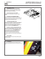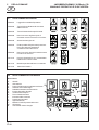
1
24493G-IT (rev.1) Safety and Operation Manual Manuale Operativo e di Sicurezza Fairway 305 Series: CG000301 onwards - Engine type: Kubota V1505 Product code: JGPP010 Series: CG200301 onwards - Engine type: Kubota V1505-Turbo Product code: JGPP010T WARNING: If incorrectly used this machine can cause severe injury. Those who use and maintain this machine should be trained in its proper use, warned of its dangers and should read the entire manual before attempting to set up, operate, adjust or service the machine. AVVERTENZA: Questa macchina può causare gravi infortuni se viene utilizzata in modo errato. Prima di accingersi ad approntare, usare, mettere a punto o eseguire la manutenzione di questa macchina, coloro che la utilizzano ed i responsabili della manutenzione devono essere addestrati all’impiego della macchina, devono essere informati dei pericoli, e devono leggere l’intero manuale. RJ 100 122003 © 2004, Ransomes Jacobsen Limited. All Rights Reserved 1 CONTENTS GB CONTENTS JACOBSEN FAIRWAY 305 Series CG SAFETY AND OPERATORS MANUAL PAGE 2 2.1 2.2 INTRODUCTION IMPORTANT ...................................................................................................... 2 PRODUCT IDENTIFICATION .............................................................................. 2 3 3.1 3.2 3.3 3.4 3.5 3.6 3.7 3.8 3.9 SAFETY INSTRUCTIONS OPERATING INSTRUCTIONS ............................................................................ 3 SAFETY SIGNS .................................................................................................. 3 STARTING THE ENGINE .................................................................................... 3 DRIVING THE MACHINE .................................................................................... 3 TRANSPORTING ............................................................................................... 3 LEAVING THE DRIVING POSITION .................................................................... 4 SLOPES ............................................................................................................ 4 BLOCKED CUTTING CYLINDERS ...................................................................... 4 ADJUSTMENTS, LUBRICATION AND MAINTENANCE ..................................... 4/5 4 4.1 4.2 4.3 4.4 4.5 4.6 4.7 4.8 4.9 SPECIFICATIONS ENGINE SPECIFICATION ................................................................................... 6 MACHINE SPECIFICATION ................................................................................ 6 DIMENSIONS .................................................................................................... 6 VIBRATION LEVEL ............................................................................................ 6 SLOPES ............................................................................................................ 7 RECOMMENDED LUBRICANTS ........................................................................ 7 CUTTING PERFORMANCE ................................................................................ 7 CUTTING PERFORMANCE (AREA) ................................................................... 7 CONFORMITY CERTIFICATES ........................................................................... 8 5 5.1 5.2 DECALS SAFETY DECALS ............................................................................................. 10 INSTRUCTION DECALS ................................................................................... 10 6 6.1 6.2 6.3 6.4 6.5 6.6 6.7 6.8 6.9 6.10 6.11 6.12 6.13 6.14 6.15 6.16 6.17 CONTROLS STARTER SWITCH .......................................................................................... 11 THROTTLE CONTROL ..................................................................................... 11 STEERING WHEEL RAKE ADJUSTMENT ........................................................ 11 TRACTION FOOTPEDAL FORWARD/REVERSE ............................................. 11 FOOTPEDAL NEUTRAL LATCH ....................................................................... 11 SPEED LIMITER ............................................................................................... 12 PARKING BRAKE ............................................................................................. 12 HYDRAULIC LIFT LEVER ................................................................................. 12 UNIT COUNTERBALANCE CONTROL .............................................................. 13 VARIABLE CYLINDER SPEED .......................................................................... 13 BACKLAPPING LEVER .................................................................................... 13 CUTTING UNIT SWITCHES .............................................................................. 14 UNIT TRANSPORT STOP ................................................................................ 14 INSTRUMENT PANEL ....................................................................................... 15 HOURMETER ................................................................................................... 15 REEL STOP LEVER .......................................................................................... 16 BONNET RELEASE KEY ................................................................................... 16 7 7.1 7.2 7.3 7.4 7.5 7.6 7.7 7.8 OPERATION DAILY INSPECTION .......................................................................................... 17 OPERATOR PRESENCE AND SAFETY INTERLOCK SYSTEM ......................... 18 OPERATING PROCEDURE ............................................................................... 19 STARTING THE ENGINE ................................................................................... 20 DRIVING ........................................................................................................... 20 MOWING .......................................................................................................... 21 TO STOP THE ENGINE ..................................................................................... 21 PUSHING THE MACHINE WITH THE ENGINE STOPPED ................................. 21 8 8.1 8.2 ADJUSTMENTS HEIGHT OF CUT (SEE CUTTING UNIT MANUAL) ............................................. 22 SEAT ................................................................................................................ 22 9 9.1 9.2 MAINTENANCE LUBRICATION AND MAINTENANCE CHART .................................................... 23 DAILY CHECKS ................................................................................................ 25 10 GUARANTEE / SALES & SERVICE ................................................................... 26 GB-1 2 JACOBSEN FAIRWAY 305 Series CG SAFETY AND OPERATORS MANUAL INTRODUCTION GB 2.1 IMPORTANT IMPORTANT: This is a precision machine and the service obtained from it depends on the way it is operated and maintained. This SAFETY AND OPERATORS MANUAL should be regarded as part of the machine. Suppliers of both new and second-hand machines are advised to retain documentary evidence that this manual was provided with the machine. This machine is designed solely for use in customary grass cutting operations. Use in any other way is considered as contrary to the intended use. Compliance with and strict adherence to the conditions of operation, service and repair as specified by the manufacturer, also constitute essential elements of the intended use. Before attempting to operate this machine, ALL operators MUST read through this manual and make themselves thoroughly conversant with Safety Instructions, controls, lubrication and maintenance. Accident prevention regulations, all other generally recognized regulations on safety and occupational medicine, and all road traffic regulations shall be observed at all times. Any arbitrary modifications carried out on this machine may relieve the manufacturer of liability for any resulting damage or injury. 2.2 PRODUCT IDENTIFICATION B A C D GB-2 E A B C D E Machine Name Serial Number Year of Manufacture Machine Weight Engine Power 3 SAFETY INSTRUCTIONS JACOBSEN FAIRWAY 305 Series CG SAFETY AND OPERATORS MANUAL GB This safety symbol indicates important safety messages in this manual. When you see this symbol, be alert to the possibility of injury, carefully read the message that follows, and inform other operators. • 3.1 • • • • OPERATING INSTRUCTIONS Ensure that the instructions in this book are read and fully understood. No person should be allowed to operate this machine unless they are fully acquainted with all the controls and the safety procedures. Never allow children or people unfamiliar with these instructions to use this machine. Local regulations may restrict the age of the operator. • • • • 3.2 • 3.3 • • 3.4 • • • • SAFETY SIGNS It is essential all safety labels are kept legible, if they are missing or illegible they must be replaced. If any part of the machine is replaced and it originally carried a safety label, a new label must be affixed to the replacement part. New safety labels are obtainable from Ransomes dealers. STARTING THE ENGINE Before starting the engine check that the brakes are applied, drives are in neutral, guards are in position and intact, and bystanders are clear of the machine. Do not run the engine in a building without adequate ventilation. DRIVING THE MACHINE Before moving the machine, check to ensure that all parts are in good working order, paying particular attention to brakes, tyres, steering and the security of cutting blades. Replace faulty silencers, mow only in daylight or good artificial light Always observe the Highway Code both on and off the roads. Keep alert and aware at all times. Watch out for traffic when crossing or near roadways. Stop the blades rotating before crossing surfaces other than grass. • • • 3.5 • • • • Remember that some people are deaf or blind and that children and animals can be unpredictable. Keep travelling speeds low enough for an emergency stop to be effective and safe at all times, in any conditions. Remove or avoid obstructions in the area to be cut, thus reducing the possibility of injury to yourself and/or bystanders. When reversing, take special care to ensure that the area behind is clear of obstructions and/or bystanders. DO NOT carry passengers. Keep in mind that the operator or user is responsible for accidents or hazards occurring to other people or their property. When the machine is to be parked, stored or left unattended, lower the cutting means unless the transport locks are being used. While mowing, always wear substantial footwear and long trousers. Do not operate the equipment when barefoot or wearing open sandals. Check the grass catcher frequently for wear or deterioration. After striking a foreign object. Inspect. the lawnmower for damage and make repairs before restarting and operating the equipment. If the machine starts to vibrate abnormally, check immediately. TRANSPORTING Ensure that the cutting units are securely fastened in the transport position. Do not transport with cutting mechanism rotating. Drive the machine with due consideration of road and surface conditions, inclines and local undulations. Sudden decelerating or braking can cause the rear wheels to lift. Remember that the stability of the rear of the machine is reduced as the fuel is used. GB-3 3 JACOBSEN FAIRWAY 305 Series CG SAFETY AND OPERATORS MANUAL SAFETY INSTRUCTIONS GB 3.6 • • LEAVING THE DRIVING POSITION Park the machine on level ground. Before leaving the driving position, stop the engine and make sure all moving parts are stationary. Apply brakes and disengage all drives. Remove the starter key. 3.7 SLOPES TAKE EXTRA CARE WHEN WORKING ON SLOPES • Local undulations and sinkage will change the general slope. Avoid ground conditions which can cause the machine to slide. • Keep machine speeds low on slopes and during tight turns. • Sudden decelerating or braking can cause the rear wheels to lift. Remember there is no such thing as a “safe” slope. • Travel on grass slopes requires particular care. • • • • • • • • DO NOT USE ON SLOPES GREATER THAN 15° • IMPORTANT: When working on any slope set the weight transfer, if fitted to its maximum (+) setting. 3.8 BLOCKED CUTTING CYLINDERS • Stop the engine and make sure all moving parts are stationary. • Apply brakes and disengage all drives. • Release blockages with care. Keep all parts of the body away from the cutting edge. Beware of energy in the drive which can cause rotation when the blockage is released. • Keep other people away from the cutting units as rotation of one cylinder can cause the others to rotate. 3.9 ADJUSTMENTS, LUBRICATION AND MAINTENANCE • Stop the engine and make sure all moving parts are stationary. • Apply brakes and disengage all drives. • Read all the appropriate servicing instructions. • Use only the replacement parts supplied by the original manufacturer. • When adjusting the cutting cylinders take care not to get hands and feet trapped when rotating cylinders. • Make sure that other people are not touching any cutting units, as rotation of one cylinder can cause the others to rotate. • To reduce the fire hazard, keep the engine, silencer and battery compartments free of grass, leaves or excessive grease. • Replace worn or damaged parts for safety. GB-4 • • • • • • • When working underneath lifted parts or machines, make sure adequate support Is provided. Do not dismantle the machine without releasing or restraining forces which can cause parts to move suddenly. Do not alter engine speed above maximum quoted in Engine Specification. Do not change the engine governor settings or overspeed the engine. Operating the engine at excessive speed may increase the hazard of personal injury. When refuelling, STOP THE ENGINE, DO NOT SMOKE. Add fuel before starting the engine, never add fuel while the engine is running. Use a funnel when pouring fuel from a can into the tank. Do not fill the fuel tank beyond the bottom of the filler neck. Replace all fuel tank and container caps securely. Store fuel in containers specifically designed for this purpose. Refuel outdoors only and do not smoke while refuelling. If fuel is spilled, do not attempt to start the engine but move the machine away from the area of spillage and avoid creating any source of ignition until fuel vapours have dissipated. Allow the engine to cool before storing in any enclosure. Never store the equipment with fuel in the tank inside a building where fumes may reach an open flame or spark. If the fuel tank has to be drained, this should be done outdoors. Do not spill fuel onto hot components. When servicing batteries, DO NOT SMOKE, and keep naked lights away. Do not place any metal objects across the terminals. 3 SAFETY INSTRUCTIONS GB JACOBSEN FAIRWAY 305 Series CG SAFETY AND OPERATORS MANUAL DANGER - Indicates an imminently hazardous situation which, if not avoided, WILL result in death or serious injury. IMPORTANT: Transport speed is for highway use only. Never select transport speed on grass areas or uneven or unsurfaced roads or tracks. WARNING - Indicates a potentially hazardous situation which, if not avoided, COULD result in death or serious injury. The operating Instructions for the Cutting Units are contained in a separate Publication . CAUTION - Indicates a potentially hazardous situation which, if not avoided, MAY result in minor or moderate injury and property damage. It may also be used to alert against unsafe practices. WARNING WARNING Hydraulic Fluid escaping under pressure can penetrate skin and do serious damage. Immediate medical assistance must be sought. WARNING Batteries produce explosive gases and contain corrosive acid and supply levels of electrical current high enough to cause burns. California Proposition 65 Engine Exhaust, some of its constituents, and certain vehicle components contain or emit chemicals known to the state of California to cause cancer and birth defects or other reproductive harm. WARNING DO NOT USE ON SLOPES GREATER THAN 15° WARNING Before releasing transport latches it is important that all cutting units are fully raised. 1. Park the machine on level ground. 2. With the engine running at operating speed raise the cutting units to their maximum position by operating lift levers whilst seated in the driving position. 3. Disengage drives, stop the engine and make sure all moving parts are stationary. Apply brakes and remove the starter key. 4. transport latches can now be released. GB-5 4 JACOBSEN FAIRWAY 305 Series CG SAFETY AND OPERATORS MANUAL SPECIFICATIONS GB 4.1 ENGINE SPECIFICATION Fuel Tank Capacity: Kubota 28KW (38HP) @ 3000 RPM, 4 cylinder (in line) vertical Diesel engine, 4 stroke, water cooled, 1498cc (91.44 cu.in) with 12V electric start. Model: V1505-BBS-EC-1 Maximum Speed: 3000 ± 50 RPM (No load) Idle Speed: 1500 RPM Oil Sump Capacity:6.0 litres (10.56 Imp.pints) Fuel: No. 2-D Diesel fuel (ASTM D975) 45.4 litres (10 Imp. galls) 12 US galls TYPE: Hydraulic Tank Capacity: Battery: Exide 093 (SAE 500) 4.3 DIMENSIONS Width of cut: 2.94 metres (116in) Overall width: 3.22 metres (126.8in) Overall width: 2.52 metres (99.2in) (transport) Overall height: 1.6 metres (63in) Overall length: 2.75 metres (113.4in) Overall weight of machine: 1515 kg (3340lb) TYPE: Kubota 34.7KW (46.5HP) @ 3000 RPM, 4 cylinder (in line) Turbo charged Diesel engine, 4 stroke, water cooled, 1498cc (91.44 cu.in) with 12V electric start. Model: V1505-TBS-1-S1 Maximum Speed: 3000 ± 50 RPM (No load) Idle Speed: 1500 RPM Oil Sump Capacity:6.4 litres (11.26 Imp.pints) Fuel: No. 2-D Diesel fuel (ASTM D975) 4.2 37.8 litres (8.3 Imp. galls) 10 US galls 4.4 VIBRATION LEVEL 4.4.1 VIBRATION LEVEL The machine was tested for whole body and hand/ arm vibration levels. The operator was seated in the normal operating postion with both hands on the steering mechanism. The engine was running and the cutting device was rotating with the machine stationary. MACHINE SPECIFICATION Frame construction:Heavy duty formed steel chassis with box section frame rails. Cutting unit drive: Fixed displacement hydraulic motors directly coupled to cutting unit. Transmission: Full time 4-wheel drive. Direct coupled variable displacement pump to direct coupled 29 cu in front, 21 cu in rear wheel motors. Speeds: Cutting: 0 - 12km/h (0 - 7.5 mph) FORWARD Transport: 0 - 14km/h (0 - 8.5mph) FORWARD Reverse: 0 - 6.4km/h (0 -4 mph) Steering: Hydrostatic power steering, with adjustable tilt steering wheel. Brakes: Hydrostatic braking with mechanical type band parking brakes, 260mm x 45mm (10.25in x 1.75in) on front wheels. Standard ISO 5349: 1986 Mechanical vibration. Guidelines for the measurement and the assessment of human exposure to hand-transmitted vibration. Max LH or RH FAIRWAY 305 SeriesCG0 Hand / Arm Acceleration level Accelerations m/s 2 X Aeq Y Aeq Z Aeq 0.636 0.611 0.620 Dominant Value 0.636 Standard ISO 2631-1: 1985 Evaluation of human exposure to whole body vibration -- Part 1: General requirements. FAIRWAY 305 SeriesCG0 Whole Body Acceleration level Mean Seat Location Floor Location Accelerations m/s 2 Accelerations m/s 2 x y z x y z 0.01 0.0181 0.0469 0.01 0.0178 0.0333 TYRE PRESSURES Front Wheel Rear Wheel Product Fairw ay 250, 305, 405 AR 250 GB-6 Tyre Siz e Tyre Type 26.5 x 14.00 - 12 Titan Ultra Trac 4pr Tyre Pressure 1 4 - 2 0 p si 1.00 - 1.37 bar Tyre Siz e Tyre Type 20 x 10.00 - 8 Titan Ultra Trac 4pr Tyre Pressure 1 4 - 2 0 p si 1.00 - 1.37 bar 4 SPECIFICATIONS JACOBSEN FAIRWAY 305 Series CG SAFETY AND OPERATORS MANUAL GB 4.4.2 VIBRATION LEVEL (TURBO) When the machine was tested for hand/arm vibration levels. The operator was seated in the normal operating position with both hands on the steering mechanism. The engine was running and the cutting device was rotating with the machine stationary. 4.5 SLOPES DO NOT USE ON SLOPES GREATER THAN 15° The slope 15° was calculated using static stability measurements according to the requirements of EN 836. The Machinery Safety Directive 98/37/EC By compliance to: The Lawnmower Standard EN836:1997 Referenced to hand/Arm: EN1033:1996 Engine oil: Should be to MIL-L-2104C or to A.P.I. Classification SE/SF/SG grades. [10W-30] Hydraulic Oil: To A.P.I. Classification CE/SF grades SAE 10W-30 Grease: Shell Darina R2, or equivilant. Information Supplied for Physical Agents Directive 2002/44/EC By reference to: Hand/Arm Standards: BS EN ISO 5349-1 (2001) BS EN ISO 5349-2 (2001) 4.7 Max LH or RH Jacobsen Fairw ay 305 Turbo Series: CG2 Hand / Arm Acceleration level Accelerations m/s 4.6 RECOMMENDED LUBRICANTS CUTTING PERFORMANCE 2 Mean Value of X, Y, Z Aeq 46 cuts per meter at 12 km/hr with 7-knife cutting head units. 0.37 When the machine was tested for Whole Body vibration levels. The operator was seated in the normal operating position with both hands on the steering mechanism. The cutting device was rotating with the machine driven in a straight line at 6 Km/hr on a level freshly cut lawn. The Machinery Safety Directive 98/37/EC By compliance to: Whole Body EN1032:2003 72 cuts per meter at 12 km/hr with 11-knife cutting head units. 4.8 CUTTING PERFORMANCE (AREA) 3.175 hectares/hr. at 12 km/hr. ( 7.85 acres/hr at 7.5 mph) 10% allowance is included for normal overlaps and turning at the end of each cut. Information Supplied for Physical Agents Directive 2002/44/EC By reference to: Whole Body Standards BS EN ISO 2631-1 (1997) Max LH or RH Foot Jacobsen Fairw ay 305 Turbo Series: CG2 Whole Body Acceleration level Accelerations m/s 2 Mean Value of X, Y, Z Aeq max 0.65 Seat Location Jacobsen Fairw ay 305 Turbo Series: CG2 Whole Body Acceleration level Accelerations m/s 2 Mean Value of X, Y, Z Aeq max 0.47 GB-7 4 SPECIFICATIONS GB 4.9 JACOBSEN FAIRWAY 305 Series CG SAFETY AND OPERATORS MANUAL CONFORMITY CERTIFICATES EC Declaration of Conformity • Déclaration de Conformité CE • EG Conformiteits-Declaratie • EG-Konformitatsbescheinigung • Certificato di Conformità CE • EF Konformitetserklæring • EU Uppfyllandecertifikat • Ilmoitus yhdenmukaisuudesta ey:n sääntöjen kanss • Declaración de Conformidad de la CE • Declaração de Conformidade da CE We the undersigned • Nous, soussignés • Wij, ondergetekenden • Wir, die Unterzeichnenden • Noi sottoscritti Undertegnede • Undertecknarna • Me allekirjoittaneet • Los abajo firmantes • Nós, abaixo assinados Ransomes Jacobsen Limited West Road, Ransomes Europark, Ipswich, England, IP3 9TT Declare that the machine Described Below • Certifions que la machine suivante • verklaren dat onderstaand beschreven machine • erklären, dass die nachfolgend beschriebene Maschine • Dichiariamo che la macchina descritta di seguito • Erklærer, at følgende maskine • Deklarerar att den maskin som beskrivs nedan • vahvistamme, että alla kuvattu kone • Certificamos que la máquina descrita abajo • declaramos que a máquina a seguir descrita Make & Type • Nom & Type • Merk & Type • Marke und Typ • Marca e tipo • Fabrikat og type • Fabrikat & typ • Malli ja tyyppi • Marca y Tipo • Marca & Tipo .............. Jacobsen Fairway 305 Category • Modèle •Categorie • Kategorie • Categoria • Kategori • Luokka • Categoría • Categoria ......................................................................................................... Ride on Cylinder Mower Series • Série • Serie • Sarja .............................................................................................. CG0 & CG2 Engine • Motor • Moteur • Motore • Moottori ....................................................................... Kubota Type • Typ • Tipo • Tyyppi .................................................................................................. V1505-E & V1505-T Net Installed Power • Puissance nette • Netto geïnstalleerd vermogen • installierte Antriebsleistung • Potenza installata netta • Nettoeffekt installere • Installerad nettoeffekt • Asennettu nettoteho • Potencia instalada neta • Potência real instalada ....................................................................................................... 28 KW & 34.7KW Cutting Width • Largeur de coupe • Maaibreedte • Schnittbreite • Larghezza di taglio • Klippebredde • Klippbredd • Leikkuuleveys • Anchura de corte • Potência real instalada ....................................................................... 294cm Complies with the provisions of the following European directives and amendments and the regulations transposing it into national law • Est conforme aux prescriptions des normes, modifications et règles européennes suivantes • voldoet aan de bepalingen van de volgende Europese Richtlijnen en Amendementen, alsmede aan de verordeningen die deze omzetten in nationale wetgeving • den Bestimmungen der folgenden Europa-Richtlinien einschließlich aller Änderungen und Ergänzungen sowie den Vorschriften, die diese in das nationale Recht umsetzen, entspricht • soddisfa quanto previsto dalle seguenti direttive ed emendamenti europei e dalle normative che li riportano in legge nazionale • Overholder bestemmelserne i følgende EF-direktiver med ændringer og i de forordninger, hvorved de omsættes til national lov • Uppfyller kraven i följande europeiska direktiv med tillägg och regler transponerade till nationell lagstiftning • täyttää seuraavana mainittujen Euroopan direktiivien ja muutosten ja säännösten asettamat edellyt Machinery Safety Directive • Directive de sécurité des machines • Richtlijn Machineveiligheid • Richtlinie zur Maschinensicherheit • Direttiva sulla sicurezza del macchinario • Maskinsikkerhedsdirektivet • Maskinsäkerhetsdirektiv • Koneen turvallisuutta koskeva direktiivi • Directiva de seguridad de maquinaria • Directiva de segurança de máquinas ................ 98/37/EC EMC Directive • Directive de compatibilité électromagnétique • EMC Richtlijn • EMK-Richtlinie • Direttiva EMC • EMC-direktivet • Elektromagnetiskt kompatibilitetsdirektiv • EMC-direktiivi • Directiva EMC ............................................................................................. 89/336/EC ROPS Directive • Directive de ROPS • ROPS Richtlijn • ROPS-Richtlinie • Direttiva ROPS • ROPS-direktivet • ROPS direktiv • ROPS-direktiivi • Directiva ROPS ...... 86/298/EC Noise in the Environment Directive • Directiv • Richtlijn Milieulawaa • Richtlinie zum Umgebungslärm • Direttiva sulla rumorosità nell’ambiente • Støjemissionsdirektivet • Bullerdirektiv • Melu ympäristöä koskevassa direktiivissä • Directiva sobre ruido en el ambiente • Directiva Ruído no Ambiente ................................ 2000/14/EC Measured Sound Power Level • Niveau de puissance sonore assuré • Gegarandeerd geluidsvermogenniveau • Garantierter Schallleistungspege • Livello di potenza del suono misurato • Målt lydeffektniveau • Uppmätt ljudfraftsnivå • Mitattu åånitehon taso • Nivel de Potencia Sonora • Nívelde intensidade de som medido .. 101 dB(A) LWA Guaranteed Sound Power Level • Niveau de puissance sonore assuré • Gegarandeerd geluidsvermogenniveau • Garantierter Schallleistungspege • Livello di potenza del suono misurato • Garanteret lydeffektniveau • Garanterad ljudtrycksnivå • Taattu äänitehon taso • Nivel Garantizado de Potencia Sonora • Nível garantido de intensidade sonora .............................................................................. 105 dB(A) LWA GB-8 4 SPECIFICATIONS GB JACOBSEN FAIRWAY 305 Series CG SAFETY AND OPERATORS MANUAL Conformity Assessment Procedure • Procédure de conformité•évaluation • Conformiteitsbeoordelingsprocedur • Verfahren zur Beurteilung der Konformität • Procedura di valutazione conformità • Procedure for overensstemmelsesvurdering • Procedur för utvärderande av uppfyllande • Yhdenmukaisuuden arviointiproseduuri • Procedimiento de evaluación de conformidad • Processo de avaliação de conformidade Annex VI, Part 1• Annexe VI, Part 1 • Bijlage VI, Part 1 • Anlage VI, Part 1 • Allegato VI, Part 1 • Anneks VI, Part 1 • Annex VI, Part 1 • Liite VI, Part 1 • Anexo VI, Part 1 • Anexo VI, Part 1 U.K. Notifiable Body (No.1088) • Institut britannique à notifie(No.1088)r • Britse onderzoeksinstantie (No.1088) • in GB zu informierende Institution (No.1088) • Ente notificabile Gran Bretagna • (No.1088) • Organ, som skal underrettes (No.1088) • Brittiskt meddelandeorgan (No.1088) • Ison-Britannian ilmoitusosapuoli (No.1088) • Cuerpo notificable en el Reino Unido (No.1088) • Entidade a notificar no Reino Unido ( No.1088) Sound Research Laboratories Limited Holbrook House, Little Waldingfield Sudbury, Suffolk CO10 0TH Operator Ear Noise Level • Bruit au niveau des oreilles de l’opérateur • Geluidsniveau op oorhoogte bediener • Schallpegel am Ohr des Fahrers • Livello rumorosità orecchio operatore • Støjniveau ved betjening • Bullernivå vid operatörens öron • Käyttäjän korvaan kohdistuva äänitaso • Nivel de ruido en el oido del operari • Nível de ruído nos ouvidos do operador ............... 84.1 dB(A)Leq (98/37/EC) Complies with the following harmonised standard or technical provisions • est conforme aux normes harmonisées • Voldoet aan de volgende geharmoniseerde norm of technische bepalingen • Diese Maschine entspricht den folgenden harmonisierten Normen oder technischen Bestimmungen • Rispetta il seguente standard armonizzato o requisiti tecnici • Overholder følgende harmoniserede standardbestemmelser eller tekniske bestemmelser • Uppfyller följande harmoniserade standard eller tekniska definitione • täyttää seuraavat harmonisoidut standardit tai tekniset edellytykset • Cumple con los siguientes estándares de hramonización o provisiones técnicas • Está em conformidade com a norma harmonizada ou com as provisões técnicas seguintes Machinery Safety • Sécurité des machines • Machineveiligheid • Maschinensicherhei • Sicurezza del macchinario • Maskinsikkerhed • Maskinsäkerhet • Koneen turvallisuus • Seguridad de maquinaria • Segurança de máquinas .................................................................................................... EN836 Hand Transmitted Vibration • Vibrations transmises aux mains • Via de hand overgebrachte trilling • Auf das Hand-Arm-System übertragene Schwingungen • Vibrazione trasmessa dalla mano • Håndoverført vibration • Handöverförda vibrationer • Käsivälitteinen tärinä • Vibración transmitida a la mano • Vibrações transmitidas através das mãos ........................................................................ ISO5349: 1986 Whole Body Vibration • Vibrations du corps entier • Trilling hele lichaam • Auf den gesamten Körper übertragene Schwingungen • Vibrazione di tutto il corpo • Vibration i hele kroppen • Hel kropps vibrationer • Koko kehoon kohdistuva tärinä • Vibración de todo el cuerpo • Vibração em todo o corpo ................................................. ISO2631-1: 1985 Keeper of Technical File, Place & Date of Declaration • Lieu & Date de déclaration • Plaats & datum verklaringsaflegging • Ort und Datum dieser Erklärung • Luogo e data della dichiarazione • Sted og dato for erklæringen • Plats & datum för deklaration • Lausunnon paikka ja päivämäärä • Lugar y fecha de la declaración • Local e data da declaração Technical Director Ransomes Jacobsen Limited West Road, Ransomes Europark, Ipswich, England, IP3 9TT 01.02.2005 T Lansdell Technical Director Certificate Number • Numéro du certificat • Certificaatnummer • Zertifikat Nummer • Numero certificato • Certifikatnummer • Certifikat nummer • Sertifikaattinumero • Número de certificado • Número do Certificado 4118269 (Rev.3) GB-9 5 DECALS GB 5.1 SAFETY DECALS A903491 Read Operator's Manual. A903489 Keep a Safe Distance from the Machine. A903492 Stay Clear of Hot Surfaces. A903488 Do Not Open or Remove Safety Shields While the Engine is Running. A903494 Caution Rotating Blades. A903493 Avoid Fluid Escaping Under Pressure. Consult Technical Manual for Service Procedures. A903490 Do Not Remove Safety Shields While Engine is Running. A911410 Danger of Explosion if the Battery Terminals are Short Circuited. A911416 Maximum permitable working slope. A911434 Caution Diesel Fuel 5.2 INSTRUCTION DECALS Description A. B. C. D. E. F. G. H. I. J. K. L. M. N. GB-10 Diesel Fuel Hydraulic Oil Jacking Point Cutting Unit Lift Fwd/Rev Traction Pedal Cutter Engage Weight Transfer Parking Brake Ignition Switch Tyre Pressure CE Approval Maximum Sound Power Level Engine Rev's Cutting cylinder speed. JACOBSEN FAIRWAY 305 Series CG SAFETY AND OPERATORS MANUAL 6 CONTROLS GB JACOBSEN FAIRWAY 305 Series CG SAFETY AND OPERATORS MANUAL 6.1 STARTER KEY SWITCH The starter key (A) should be turned clockwise to the 'pre-heat' (No. 2) position to heat the glowplugs when the green warning lamp goes out, on warning lamp disply module, turn the starter key clockwise to the 'start' (No. 3) position to start the engine. After starting, the key should be released and allowed to return automatically to the 'on' (No. 1) position for normal running. 6.2 THROTTLE CONTROL LEVER The lever (B) should be moved away from the operator to increase the engine speed and towards the operator to decrease the engine speed. NOTE: Engine should be used at full speed. 6.3 STEERING WHEEL RAKE ADJUSTMENT The steering wheel is adjustable for rake. The clamping release knob (A) is situated on the side of the control console on the left hand side. To adjust turn the clamping knob anticlockwise to release and pivot the steering wheel backwards and forwards to obtain desired setting then lock in position by turning clamping knob clockwise. 6.4 TRACTION FOOT PEDAL To move the machine forward press the front of the foot pedal (A). To reverse depress the rear of the foot pedal. When the pedal is released it will return to its neutral position. 6.5 NEUTRAL LATCH (B) Has two functions: 1. The engine cannot be started when the Neutral Latch is depressed. 2. The FWD/REV pedal will not work as described if the Neutral Latch is not simultaneously depressed. GB-11 6 CONTROLS GB 6.6 SPEED LIMITER The speed limiter (A) is operated by pivoting the lever under the footpedal. When positioned under the footpedal the machine is limited to cutting speed, when not under the footpedal transport speed is availabe. 6.7 PARK BRAKES Push the pedal forward (A) until it locks to set parking brake. Release parking brake by pushing the brake pedal at the same time lever (B) is pulled up. 6.8 HYDRAULIC LIFT LEVER The cutting units can be raised and lowered by control lever (A) situated on the right hand side of the operators seat and can be operated as follows: To lift: Move the lever backwards and hold in position until the units are at the required height. To lower: Move the lever forwards and hold in this position, the units will lower to ground level. The lever automatically returns to a neutral position when released. NOTE: If any unit is raised out of work then lowered into work again the blades will not rotate until the mow foot switch is depressed. NOTE: The units will only lift and lower when the engine is running. GB-12 JACOBSEN FAIRWAY 305 Series CG SAFETY AND OPERATORS MANUAL 6 CONTROLS GB JACOBSEN FAIRWAY 305 Series CG SAFETY AND OPERATORS MANUAL 6.9 UNIT COUNTERBALANCE CONTROL Cutting unit ground pressure can be varied within preset limits and is controlled by the handwheel (A) on the right hand side of the operator's seat located next to the lift/lower lever. The handwheel is turned clockwise to reduce the groundweight of the cutting unit, improving slope climbing ability. The handwheel is turned anti clockwise to increase the ground weight of the unit. Increased down pressure will reduce the likelyhood of cutting unit bounce when cutting undulating ground. When cutting level ground the normal setting is midway way between the maximum and minimum positions. 6.10 VARIABLE CYLINDER SPEED The speed of rotation of the cutting cylinders is adjustable by means of the handwheel (A) situated on the left hand side of the operator. Cylinder speed should be set to maximum in normal cutting conditions. In very long growth conditions, cylinder speed should be reduced to obtain best finish,cylinder speed should also be reduced when cutting very short, dry grass to prevent excesive cylinder and bottom blade wear. Rotate the hand wheel clockwise to increase cylinder speed, anticlockwise to decrease cylinder speed. 6.11 BACKLAPPING LEVER Sets reel rotational direction with three positions: (a) forward for mowing, (b) reverse for backlapping and (c) neutral. See the separate cutting unit operator's manual for an explanation of the backlapping procedure. GB-13 6 CONTROLS GB 6.12 CUTTING UNIT SWITCHES To commence cutting ensure speed limiter is in mow position and the units have been lowered. Push bottom of the rocker switch (G) and depress foot switch (A) Push top of rocker switch to stop cutter unit rotation. (Cutting units stop rotating automatically when raised.) 6.13 UNIT TRANSPORT STOP Depressing the pedal (A) while lifting the cutting units allows the cutting units to be raised for machine transport. GB-14 JACOBSEN FAIRWAY 305 Series CG SAFETY AND OPERATORS MANUAL 6 CONTROLS GB JACOBSEN FAIRWAY 305 Series CG SAFETY AND OPERATORS MANUAL 6.14 INSTRUMENT PANEL A. ENGINE PREHEAT INDICATOR LAMP Colour green, on when the ignition switch is turned clockwise to the pre-heat position. Once the lamp goes out the engine can be started. B. ENGINE TEMPARATURE GUAGE Indicates current temparature of engine, whilst running. C. HYDRAULIC OIL WARNING LAMP Colour red, on when the hydraulic oil temperature reaches a preset level. If the lamp comes on bring the machine to a stop, disengage the cutting units, apply the parking brake and stop the engine. D. CHARGING WARNING LAMP Colour red, on when ignition is switched on and will go out when the engine is started. If the light comes on while the engine is running, the fan belt may be slipping or broken or a fault in the electrical system is indicated and should be investigated. STOP IMMEDIATELY. E. ENGINE OIL PRESSURE WARNING LAMP Colour red, on when the ignition is switched on, and will go out once the engine has started. If the light comes on while the engine is running - STOP IMMEDIATELY as this indicates that the engine oil pressure is too low. Check the level of oil in the sump and top up as necessary. Check the oil pressure sender switch. Continued operation may cause extensive damage to the engine. F. FUEL GUAGE Located to the left of the engine temparature guage. Monitors fuel level. 6.15 HOURMETER Located on the lefthand side of the steering tower, above the parking brake. (A) Records engine running hours. GB-15 GB 6.16 REEL STOP LEVER Friction control that keeps cutting unit from bouncing when operating over rough ground conditions. 6.17 BONNET RELEASE KEY Release bonnet by inserting key (A) into base of latch bracket. GB-16 JACOBSEN FAIRWAY 305 Series CG SAFETY AND OPERATORS MANUAL 7 OPERATION JACOBSEN FAIRWAY 305 Series CG SAFETY AND OPERATORS MANUAL GB 7.1 DAILY INSPECTION CAUTION The daily inspection should be performed only when the engine is off and all fluids are cold. Lower implements to the ground, engage parking brake, stop engine and remove ignition key. 1. Perform a visual inspection of the entire unit, look for signs of wear, loose hardware and missing or damaged components. Check for fuel and oil leaks to ensure connections are tight and hoses and tubes are in good condition. 2. Check the fuel supply, radiator coolant level, crankcase oil level and air cleaner is clean. All fluids must be at the full mark with the engine cold. 3. Make sure all cutting units are adjusted to the same height of cut. 4. Check all tyres for proper inflation. 5. Test the operator presence and safety interlock system. GB-17 7 JACOBSEN FAIRWAY 305 Series CG SAFETY AND OPERATORS MANUAL OPERATION GB 7.2 1. OPERATOR PRESENCE AND SAFETY INTERLOCK SYSTEM The operator presence & safety interlock system prevents the engine from starting unless the neutral latch is released, and the mowing device is switched off. The system also stops the engine if the operator leaves the seat with the mowing device engaged or the neutral latch depressed. WARNING Never operate the equipment with the operator presence & safety interlock system disengaged or malfunctioning. Do not disconnect or bypass any switch. 2. Perform each of the following tests to ensure the operator presence & safety interlock system is functioning properly. Stop the test and have the system inspected and repaired if any of the tests fail as listed below: • • • The engine does not start in test 1; The engine does start during tests 2 or 3. The engine continues to run during test 4. 3. Refer to the chart below for each test and follow the check (9) marks across the chart. Shut engine off betwen each test. Test 1: Represents normal starting procedure. The operator is seated, pedal neutral latch is released, the operators feet are off the pedals and the mower engagement device is off. The engine should start. Test 2: The engine must not start if the mower engage device is on. Test 3: The engine must not start if the neutral latch is depressed. (Traction Pedal) Test 4: Start the engine in the normal manner, then turn mower engage device on and lift your weight off the seat. Test Operator Seated Neutral Latch Released Yes Yes No 1 9 9 2 9 9 3 9 4 9 No Mow er Sw itch On 9 Off Yes 9 9 9 9 Engine Starts 9 9 9 No 9 Lift your weight off seat. The cutting units must stop rotating within seven (7) seconds GB-18 7 OPERATION JACOBSEN FAIRWAY 305 Series CG SAFETY AND OPERATORS MANUAL GB 7.3 OPERATING PROCEDURE CAUTION To help prevent injury, always wear safety glasses, leather work shoes or boots, a hard hat and ear protection. 1. Under no circumstances should the engine be started without the operator seated on the tractor. 2. Do not operate tractor or attachments with loose, damaged or missing components. Whenever possible mow when grass is dry 3. First mow in a test area to become thoroughly familiar with the operation of the tractor and control levers. 4. Study the area to determine the best and safest operating procedure. Consider the height of the grass, type of terrain, and condition of the surface. Each condition will require certain adjustments or precautions. 5. Never direct discharge of material toward bystanders, nor allow anyone near the machine while in operation. The owner/operator is responsible for injuries inflicted to bystanders and/or damage to their property. CAUTION Pick up all debris you can find before mowing. Enter a new area cautiously Always operate at speeds that allow you to have complete control of the tractor 6. Use discretion when mowing near gravel areas (roadway, parking areas, cart paths, etc.). Stones discharged from the implement may cause serious injuries to bystanders and/or damage the equipment. 7. Disengage the drive motors and raise the implements when crossing paths or roads. Look out for traffic. 8. Stop and inspect the equipment for damage immediately after striking an obstruction or if the machine begins to vibrate abnormally. Have the equipment repaired before resuming operation. WARNING Before you clean, adjust, or repair this equipment, always disengage all drives, lower implements to the ground, engage parking brake, stop engine and remove key from ignition switch to prevent injuries. GB-19 7 JACOBSEN FAIRWAY 305 Series CG SAFETY AND OPERATORS MANUAL OPERATION GB WARNING DO NOT USE ON SLOPES GREATER THAN 15° 9. Slow down and use extra care on hillsides. Read Section 3.7. Use caution when operating near drop off points. 10. Never use your hands to clean cutting units. Use a brush to remove grass clippings from blades. Blades are extremely sharp and can cause serious injuries OPERATION OF THE MACHINE Read the Safety Instructions. BEFORE OPERATING FOR THE FIRST TIME • Check and adjust tyre pressure, if necessary, to 1 kg/cm2 (14 psi). • Add diesel fuel to tank if neccesary. • Check engine oil and top-up, if necessary. • Check radiator coolant and top-up, if necessary (50% antifreeze solution). • Make sure you understand the information contained in the previous sections. 7.4 STARTING THE ENGINE The following procedure is for starting cold engines. 1. Ensure the FWD/REV pedal is in the neutral position, the mow switch is off, the throttle setting is in a mid position and the parking brake is applied. 2. Turn the ignition switch to position No.2 and hold until the glow plug light goes off (5-10 sec.) 3. Turn ignition key fully clockwise to the start position and operate the starter motor until the engine starts (This should only take a few seconds) 4. When the engine starts, release the key immediately and it will return to the RUN position. 5. If the engine does not start, preheat the glow plugs and try again. GB-20 NOTES: • Warm engine - When the engine is warm because of surrounding temperature or recent operation, step No.2 of the cold engine starting procedure may be skipped (no need to preheat glow plugs). • If the engine fails to start after two tries (with preheat if necessary), wait 20 seconds and try again. • The starter motor should never be run continuously for longer than 30 seconds or it may fail. 7.5 • • • • DRIVING Release brake - Make sure the parking brake is released before attempting to go forward or reverse. Forward - Gently depress the top plate of the FWD/REV foot pedal to reach desired ground speed. Reverse - Gently depress the bottom plate of the FWD/REV foot pedal to reach desired ground speed. To stop - Gently return the FWD/REV foot pedal to the neutral position. NOTES: • Use complete foot to operate both forward and reverse. • Do not move pedal suddenly–always operate slowly and smoothly. Never move pedal violently from forward to reverse or vice versa. • Always keep foot firmly on the foot pedal– a too relaxed foot control may result in a jerky motion. 7 OPERATION JACOBSEN FAIRWAY 305 Series CG SAFETY AND OPERATORS MANUAL GB 7.6 1. MOWING Lower the units with the cutting unit lift control. 2. Ensure speed limiter is in mow position 3. Engage the cutting mechanism by pushing on the lower half of cutting unit switch and operating the floor mounted switch. 3. Release the parking brake and begin driving forward. NOTE: Always set the throttle to full for mowing, even when the grass is heavy. When the engine is labouring, reduce forward speed by easing up on the FWD/REV foot pedal. 7.7 1. 2. 3. 3. 4. 7.8 1. 2. 3. TO STOP THE ENGINE Disengage power to the cutting units with the cutting unit switch. Remove foot from the FWD/REV pedal. Set the parking brake. Move the throttle control lever to the SLOW position. Turn the ignition key to OFF. PUSHING THE MACHINE WITH THE ENGINE STOPPED To push, disengage the parking brake. Turn screw (A) located on the underside of the transmission pump 1 turn counterclockwise. Set the steering wheel so that the rear wheels are pointing straight ahead. After pushing, return screw (A) to their previous positions. DO NOT exceed the following speeds and distance when moving the machine in 'Free Wheel'. Maximum Speed: Maximum Distance: 1.5 Km/Hr (1 mph) 2Km (1 1/4 miles) DO NOT allow the machine to free wheel down slopes even when unloading down ramps. GB-21 8 ADJUSTMENTS GB 8.1 HEIGHT OF CUT See seperate cutting unit operator's manual. 8.2 SEAT (GS85/90) The seat can be adjusted for operator's weight and leg reach to provide a comfortable position for operating the machine. 1. ADJUSTMENT FOR OPERATOR WEIGHT To Adjust: The position of the adjusting knob (A) is on the front of the seat, in the centre below the seat cushion. By rotating the knob clockwise the weight capacity is increased and by rotating the knob anticlockwise the weight capacity is decreased. 2. FORE AND AFT ADJUSTMENT To Adjust: The position of the adjusting lever is on the right hand side of the seat below the seat cushion (B). By moving the lever towards the seat, the seat can be slid backwards and forwards. When in the desired position release the lever to locate in one of the pre set positions. 3. BACK REST ADJUSTMENT The back rest has three preset positions To Adjust: The position of the release lever is on the left hand side of the seat back rest (C). Move the lever upwards to move the upper part of the back rest forward. Move the lever downwards to move the upper part of the back rest rearwards. NOTE:The seat is fitted with a microswitch to sense operator presence. When the machine is fitted with a ROPS frame or cab a lap belt is fitted and should be worn at all times GB-22 JACOBSEN FAIRWAY 305 Series CG SAFETY AND OPERATORS MANUAL 9 MAINTENANCE JACOBSEN FAIRWAY 305 Series CG SAFETY AND OPERATORS MANUAL GB 9.1 LUBRICATION AND MAINTENANCE CHART B lack bullet points are operator checks and w hite bullet points are w orkshop maintenance procedures First 50 hours D aily Every 50 hours Every 100 hours Every 400 hours Every 600 hours E nd of S easo n EN GIN E C heck Oi l Level C hange Oi l z z z C lean Ai r Fi lter Element z z C hange Ai r Fi lter Element C hange Oi l Fi lter C artri dge z Replace Fuel Fi lters z z z z z z MAC H IN E C heck Interlock System z C heck/Top-up C oolant Level z C heck/D rai n Water Seperator z C heck Tyre Pressure z C heck Hydrauli c Flui d Level z C heck/C lean Engi ne Bay, Bug Screen & Radi ator z z C heck Nuts & Bolts For Ti ghtness z C heck Hydrauli c Fi tti ngs For Ti ghtness z C heck Rear Wheel Toe-i n z C heck Battery C ondi ti on C heck Belt Tensi on z z z C hange Hydrauli c Oi l & Fi lter z z D rai n & C lean Fuel Tank z z D rai n & Flush C ooli ng System z C heck Parki ng Brake Adjustment z *Service more often in dirty conditions Lubricate the Grease Fittings w ith Shell D arina R 2 grease w eekly (SEE C H AR T) GB-23 9 JACOBSEN FAIRWAY 305 Series CG SAFETY AND OPERATORS MANUAL MAINTENANCE GB z z Lubricate every 40 working hours at arrows (except lubricate all reel fittings daily). Coupling between reel and hydraulic motor should be half full of non-tracking grease. FLUID REQUIREMENTS GB-24 QUANTITY TYPE ENGINE OIL (NON TURBO) (w ith filter) 6.0 Litres 10W 30 (SE/SF/SG) ENGINE OIL (TURBO) (w ith filter) 6.4 Litres 10W 30 (SE/SF/SG) HYDRAULIC OIL (w ith filter) 37.9 Litres 10W 30 (CE/SF) RADIATOR COOLANT 5 Litres 50% ANTI-FREEZE 9 MAINTENANCE GB JACOBSEN FAIRWAY 305 Series CG SAFETY AND OPERATORS MANUAL 9.2 DAILY CHECKS (Every 8 working hours) Oil Level. Check level of oil in sump. Remove dipstick (Located in area B) wipe and replace and check that oil is up to the maximum mark. Top up with 10W30 if neccesary(A). It is important that this test is carried out with the engine cold and the vehicle parked on level ground. Hydraulic Oil Level. Check hydraulic oil level in tank. The level of oil should be maintained halfway up the sight glass (C). Top up with10W30 hydraulic oil or equivilent if neccessary. The oil level should be checked cold with the machine parked on level ground. IMPORTANT: Absolute cleanliness must be observed when filling the hydraulic tank. Oil must be filtered through a 25 micron filter before entering the hydraulic tank. Cooling System. Check coolant level in expansion tank the coolant level should be between the marks indicated on the expansion bottle. Top up if neccessary using a 50% antifreeze solution. Air Filter. If working in dusty conditions the air filter element should be examined and cleaned/replaced every 8 working hours(D). Cleaning the air filter. Remove loose dirt from element with compressed air working from the "clean" to "dirty" side. Note: Compressed air must not exceed 6bar, with the nozzle 50mm away from element. The element should be replaced after 6 cleanings. Cooling System. Check Bug Screen/Radiator & Oil cooler are all free from dust /debris and there is an uninterupted air flow to the engine. The screen should be fitted with the mesh facing the rear of the machine. Any debris should be removed with a soft hand brush. GB-25 10 GUARANTEE / SALES & SERVICE GB JACOBSEN FAIRWAY 305 Series CG SAFETY AND OPERATORS MANUAL GUARANTEE We GUARANTEE that should any defect in workmanship or material occur in the goods within TWO YEARS or two thousand hours (on models equipped with hour meters), or whichever occurs first. Exception to this warranty will be Aeration products, which are covered for a period of TWO-YEARS or five hundred hours (on models equipped with hour meters) or whichever occurs first. We will repair, or at our option, replace the defective part without making any charge for labour or for materials, provided that the claim under this guarantee is made through an authorised dealer and that the defective part shall, if we so request, be returned to us or to the dealer. This guarantee is in addition to, and does not exclude, any condition or warranty implied by law, except that we accept no liability in respect of used/second-hand goods, or in respect of defects which in our opinion are in any way or to any extent attributable to misuse, lack of reasonable care or ordinary wear and tear, or to the fitting of spares, replacements, or extra components which are not supplied or approved by us for the purpose. The use of non-recommended oil or lubricant nullifies the guarantee. Damage through transport or normal wear does not come under the guarantee. The warranty is extended to the original purchaser only and is not transferable to subsequent owners. The warranty period begins on the date the product is delivered to the end user (customer), unless otherwise agreed with the manufacturer. At the end of the first year the owner must have the product serviced by an authorised dealer to be eligible for the second year of warranty coverage. SALES & SERVICE A network of authorised Sales and Service dealers has been established and these details are available from your supplier. When service attention, or spares, are required for the machine, within or after the guarantee period your supplier or any authorised dealer should be contacted. Always quote the registered number of the machine. If any damage is apparent when delivery is made, report the details at once to the supplier of the machine. KEY NUMBERS. It is recommended that all key numbers are noted here: Starter Switch :- ......................................................................... Diesel tank :- .............................................................................. It is also recommended that the machine and engine numbers are recorded. The machine serial number is located on the registration plate and the engine serial number can be found on the rocker cover. Machine Number :- .................................................................... Engine Number :- ...................................................................... GB-26 1 INDICE JACOBSEN FAIRWAY 305 Serie: CG MANUALE OPERATIVO E DI SICUREZZA IT INDICE PAGINA 2 2.1 2.2 INTRODUZIONE IMPORTANTE .................................................................................................... 2 IDENTIFICAZIONE DEL PRODOTTO ................................................................. 2 3 3.1 3.2 3.3 3.4 3.5 3.6 3.7 3.8 3.9 ISTRUZIONI PER LA SICUREZZA ISTRUZIONI DI FUNZIONAMENTO .................................................................... 3 AVVISI DI SICUREZZA ...................................................................................... 3 AVVIO DEL MOTORE ........................................................................................ 3 GUIDA DELLA MACCHINA ................................................................................ 3 TRASPORTO .................................................................................................... 3 AL TERMINE DELLA GUIDA .............................................................................. 4 PENDII ............................................................................................................... 4 TAMBURI DI TAGLIO BLOCCATI ....................................................................... 4 REGOLAZIONI, LUBRIFICAZIONE E MANUTENZIONE ...................................... 4 4 4.1 4.2 4.3 4.4 4.5 4.6 4.7 4.8 4.9 DATI TECNICI SPECIFICHE DEL MOTORE ............................................................................... 6 SPECIFICHE DELLA MACCHINA ....................................................................... 6 DIMENSIONI ...................................................................................................... 6 LIVELLO DI VIBRAZIONE .................................................................................. 6 PENDII ............................................................................................................... 7 LUBRIFICANTI CONSIGLIATI ............................................................................ 7 PRESTAZIONI DI TAGLIO .................................................................................. 7 PRESTAZIONI DI TAGLIO (AREA) ..................................................................... 7 CERTIFICATO DI CONFORMITÀ CE ................................................................... 8 5 5.1 5.2 DECALCOMANIE DECALCOMANIE DI SICUREZZA ..................................................................... 10 DECALCOMANIE DELLE ISTRUZIONI .............................................................. 10 6 6.1 6.2 6.3 6.4 6.5 6.6 6.7 6.8 6.9 6.10 6.11 6.12 6.13 6.14 6.15 6.16 6.14 COMANDI INTERRUTTORE DELLA CHIAVE DI AVVIAMENTO .......................................... 11 LEVA DI COMANDO ACCELERATORE ............................................................. 11 REGOLAZIONE DELL’ANGOLO DI INCLINAZIONE DELLO STERZO ................ 11 PEDALE DELLA TRAZIONE ............................................................................. 11 DISPOSITIVO DI FOLLE ................................................................................... 11 LIMITATORE DI VELOCITÀ .............................................................................. 12 FRENI DI STAZIONAMENTO ............................................................................. 12 LEVA DI SOLLEVAMENTO IDRAULICA ............................................................ 12 COMANDO DI CONTROBILANCIAMENTO DELL’UNITÀ .................................. 13 VELOCITÀ DEL CILINDRO VARIABILE ............................................................ 13 LEVA DI ROTAZIONE INVERSA ........................................................................ 13 INTERRUTTORI DELL’UNITÀ DI TAGLIO .......................................................... 14 ARRESTO DI TRASPORTO DELL’UNITÀ ......................................................... 14 QUADRO PORTASTRUMENTI ......................................................................... 15 CONTAORE ...................................................................................................... 15 LEVA DI ARRESTO DELL’ELICOIDALE ............................................................ 16 CHIAVE DI RILASCIO DEL COFANO ................................................................. 16 7 7.1 7.2 7.3 7.4 7.5 7.6 7.7 7.8 FUNZIONAMENTO ............................................................................................. ISPEZIONE GIORNALIERA ............................................................................... 17 SISTEMA DI RILEVAMENTO PRESENZA OPERATORE E DISPOSITIVO AUTOMATICO DI SICUREZZA ................................................. 18 PROCEDIMENTO PER IL FUNZIONAMENTO ................................................... 19 AVVIO DEL MOTORE ....................................................................................... 20 GUIDA .............................................................................................................. 20 TAGLIO ............................................................................................................ 21 PER ARRESTARE IL MOTORE ......................................................................... 21 SPINGERE LA MACCHINA A MOTORE SPENTO ............................................. 21 8 8.1 8.2 REGOLAZIONE ALTEZZA DI TAGLIO (VEDERE MANUALE DELL’UNITÀ DI TAGlIO) ................ 22 SEDILE ............................................................................................................. 22 9 9.1 9.2 MANUTENZIONE SCHEMA DI LUBRIFICAZIONE E MANUTENZIONE .......................................... 23 VERIFICHE GIORNALIERE ................................................................................ 25 10 GARANZIA / VENDITE ED ASSITENZA ............................................................. 26 IT-1 2 JACOBSEN FAIRWAY 305 Serie: CG MANUALE OPERATIVO E DI SICUREZZA INTRODUZIONE IT 2.1 IMPORTANTE IMPORTANTE: Questa è una macchina di precisione, le cui prestazioni dipendono dal modo in cui viene gestita e mantenuta. Il MANUALE OPERATIVO E DI SICUREZZA deve essere considerato parte della macchina. I fornitori di macchine nuove ed usate sono pregati di conservare la documentazione comprovante la fornitura del presente manuale insieme alla macchina. Questa macchina è stata realizzata per il normale taglio del tappeto erboso, ed il suo utilizzo per qualsiasi altra operazione è considerato contrario all’uso previsto. Gli elementi essenziali dell’uso previsto comprendono la rigorosa osservanza delle condizioni d’impiego, manutenzione e riparazione, in conformità alle istruzioni del fabbricante. Prima di utilizzare questa macchina, TUTTI gli operatori DEVONO leggere attentamente il presente manuale e familiarizzarsi con le istruzioni per la sicurezza, i comandi, la lubrificazione e la manutenzione. Si dovranno sempre osservare le norme per la prevenzione degli infortuni, ogni altra norma sulla sicurezza e la medicina del lavoro generalmente riconosciuta, come pure tutte le disposizioni previste dal codice della strada. Eventuali modifiche arbitrarie apportate a questa macchina potranno esimere il fabbricante dalla responsabilità di danni o infortuni risultanti dalle stesse. 2.2 IDENTIFICAZIONE DEL PRODOTTO B A C D IT-2 E A B C D E Nome della macchina Numero di serie Anno di fabbricazione Peso della macchina Potenza del motore 3 ISTRUZIONI PER LA SICUREZZA IT JACOBSEN FAIRWAY 305 Serie: CG MANUALE OPERATIVO E DI SICUREZZA • Questo simbolo di sicurezza indica importanti messaggi per la sicurezza in questo manuale. Questo simbolo allerta gli utenti sulla possibilità di lesioni. Leggere attentamente il messaggio che segue e informare gli utenti. • 3.1 ISTRUZIONI DI FUNZIONAMENTO • Assicurarsi che le istruzioni di questo manuale siano lette e comprese appieno. L’uso di questa macchina non deve essere mai consentito a persone non autorizzate e non consapevoli di tutti i controlli e delle procedure di sicurezza. L’uso di questa macchina non deve essere mai consentito a bambini e persone che non conoscano le presenti istruzioni. Le norme locali vigenti possono prevedere un limite d’età per l’operatore. • • • 3.2 AVVISI DI SICUREZZA • Tutte le targhette ed i cartelli di sicurezza devono essere leggibili in tutti i tempi: se mancano o sono illeggibili, devono essere sostituiti. Se qualsiasi componente della macchina cui era originariamente affissa una targhetta di sicurezza viene sostituito, una nuova targhetta deve essere affissa al pezzo di ricambio montato. Nuove targhette di questo tipo sono disponibili presso il Reparto Ricambi Ransomes. 3.3 AVVIO DEL MOTORE • Prima di avviare il motore, controllare che i freni siano azionati, le marce siano in folle, i ripari siano in posizione ed intatti e che il personale di servizio sia lontano dalla macchina. Non far funzionare il motore in locali non adeguatamente ventilati. • • • • • • • • • 3.4 GUIDA DELLA MACCHINA • Prima di avviare la macchina, controllare per assicurarsi che tutte le sue parti siano in buone condizioni di funzionamento, prestando particolare attenzione ai freni, i pneumatici, lo sterzo e la sicurezza delle lame di taglio. Sostituire i silenziatori difettosi, tosare l’erba soltanto durante il giorno od in presenza di una buona illuminazione artificiale. • Osservare sempre il Codice della Strada, sia su strada che al di fuori di essa. Prestare in tutti i casi il massimo livello d’attenzione e prendere atto delle situazioni circostanti. Prestare attenzione al traffico se si devono attraversare delle strade o si deve lavorare in prossimità di strade. Interrompere la rotazione delle lame prima di attraversare superfici non erbose. Considerare la possibile presenza di persone non vedenti e non udenti e tenere a mente l’imprevedibilità di bambini e animali. Tenere bassa la velocità di marcia, per poter effettuare arresti d’emergenza in tutte le condizioni ed in tutti i casi. Eliminare o evitare gli ostacoli nell’area da tosare, riducendo così la possibilità di rischi per l’incolumità sia del personale che degli astanti. Durante la retromarcia prestare particolare attenzione per accertarsi che l’area alle spalle dell’operatore sia libera da ostacoli e/o dagli astanti. NON trasportare passeggeri. Tenere presente che l’operatore o l’utente è responsabile di eventuali incidenti o pericoli a cui possano essere esposte le altre persone od i loro beni. Quando la macchina deve essere parcheggiata, messa in deposito o lasciata incustodita, abbassare i dispositivi di taglio, eccetto nei casi in cui vengano adoperati i dispositivi di bloccaggio per il trasporto. Durante il taglio dell’erba, indossare sempre delle calzature robuste e pantaloni lunghi. Non azionare la macchina a piedi nudi od indossando sandali aperti. Controllare spesso che il raccoglitore dell’erba non presenti segni di usura o deterioramento. Dopo aver urtato un oggetto estraneo, ispezionare il tosaerba per verificare se vi sono danni ed effettuare le riparazioni eventualmente necessarie prima di avviare ed azionare di nuovo la macchina. Se la macchina inizia a vibrare in modo anomalo, controllarla immediatamente. 3.5 TRASPORTO • Assicurarsi che nella posizione per il trasporto le unità di taglio siano fermate in maniera sicura. Non effettuare il trasporto con il meccanismo di taglio in rotazione. Guidare la macchina tenendo conto delle condizioni della strada e delle superfici interessate, delle pendenze e ondulazioni del terreno. • IT-3 3 ISTRUZIONI PER LA SICUREZZA IT • • In caso di decelerazione o frenata improvvisa si può provocare il sollevamento delle ruote posteriori. Tenere presente che la stabilità della parte posteriore della macchina diminuisce man mano che si utilizza il carburante. 3.6 AL TERMINE DELLA GUIDA • Parcheggiare la macchina sopra un terreno livellato. Prima di lasciare la posizione di guida, fermare il motore ed accertarsi che tutte le parti in moto si siano fermate. Applicare il freno e disconnettere tutti i sistemi di marcia. Togliere la chiave di accensione. JACOBSEN FAIRWAY 305 Serie: CG MANUALE OPERATIVO E DI SICUREZZA 3.9 REGOLAZIONI, LUBRIFICAZIONE E MANUTENZIONE • Spegnere il motore ed assicurarsi che tutte le parti mobili siano ferme. Innestare i freni e scollegare tutte le trasmissioni. Leggere tutte le istruzioni pertinenti all’assistenza. Usare solo le parti di ricambio originali fornite dal produttore. Quando si regolano i tamburi di taglio tenere le mani ed i piedi ad una distanza di sicurezza perché non vengano imprigionati durante la rotazione. Assicurarsi che altre persone non tocchino le parti taglienti, perché la rotazione di un tamburo può far girare anche gli altri tamburi. Per ridurre i rischi d’incendio, mantenere il motore, i vani del motore, del silenziatore e della batteria sgombri da erba, foglie o grasso in eccesso. Sostituire le parti logore o danneggiate per salvaguardare la sicurezza. Quando si lavora al di sotto di alcuni componenti o dell’intera macchina, dopo averle sollevate, accertarsi di disporre di un supporto adeguato. Non smontare la macchina senza avere liberato o trattenuto le forze che possono causare il movimento improvviso dei componenti. Non alterare la velocità del motore al di sopra dei valori massimi stabiliti nella Specifica del Motore. Non modificare le impostazioni del regolatore del motore, né accelerare eccessivamente il motore. L’azionamento del motore a velocità eccessiva può incrementare il rischio di infortuni personali. SPEGNERE IL MOTORE E NON FUMARE quando si versa il carburante nel serbatoio. Aggiungere il combustibile prima di avviare il motore, non aggiungerlo mai a motore acceso. Usare un imbuto durante il travaso del carburante dalla tanica al serbatoio. Non riempire il serbatoio del combustibile oltre il fondo del bocchettone di rifornimento. Richiudere correttamente i tappi del serbatoio del combustibile e di tutti i contenitori. Conservare il carburante in contenitori espressamente costruiti per questo scopo. Effettuare i rifornimenti di combustibile soltanto all’aperto e non fumare durante l’operazione di rifornimento. • • • • 3.7 PENDII • • • PRESTARE PARTICOLARE ATTENZIONE QUANDO SI LAVORA IN PENDII • • • • • Le ondulazioni del terreno e l’affondamento fanno cambiare la pendenza generale. Evitare le condizioni di terreno che fanno scivolare la macchina. Moderare la velocità della macchina sui tratti in pendenza e nelle curve strette. In caso di decelerazione o frenata improvvisa si può causare il sollevamento delle ruote posteriori. Ricordare che non esistono pendenze cosiddette “sicure”. Quando si lavora su pendii erbosi esercitare particolare attenzione. • • • NON USARE SU PENDII SUPERIORI A 15° • IMPORTANTE: Quando si lavora su pendii, impostare il trasferimento del peso se montato al valore massimo (+). • 3.8 TAMBURI DI TAGLIO BLOCCATI • Spegnere il motore ed assicurarsi che tutte le parti mobili siano ferme. Innestare i freni e scollegare tutte le trasmissioni. Eliminare con cura le cause d’inceppamento. Tenere il corpo lontano dagli spigoli taglienti. Tenere a mente che l’energia di trazione può causare una certa rotazione quando si elimina l’inceppamento. Tenere le altre persone lontane dalle unità di taglio, dato che la rotazione di un cilindro può causare la rotazione anche degli altri cilindri. • • • • IT-4 • • • 3 ISTRUZIONI PER LA SICUREZZA IT • • • Se viene disperso della benzina, non tentare di avviare il motore, ma spostare la macchina lontano dall’area dove è avvenuta la dispersione, evitando di creare qualsiasi fonte di accensione, finché i vapori di benzina non si siano dispersi. Lasciar raffreddare il motore prima d’immagazzinare la macchina in un ambiente chiuso. Non conservare mai la macchina con della benzina nel serbatoio all’interno di un locale dove i vapori potrebbero venire a contatto con fiamme vive o scintille. PERICOLO - Indica una situazione pericolosa imminente, che, se non evitata, PROVOCHERÀ certamente morte o gravi lesioni. AVVISO - Indica una situazione potenzialmente pericolosa che, se non evitata, POTREBBE provocare morte o gravi lesioni. ATTENZIONE - Indica una situazione potenzialmente pericolosa che, se non evitata, PROBABILMENTE provocherà lesioni da lievi a moderate e danni a proprietà. Può essere utilizzato anche per allertare contro procedimenti non sicuri. JACOBSEN FAIRWAY 305 Serie: CG MANUALE OPERATIVO E DI SICUREZZA • • • • Se è necessario svuotare il serbatoio del combustibile, farlo all’aperto. Non disperdere del carburante sopra componenti caldi. NON FUMARE e tenere lontane le fiamme vive durante l’assistenza tecnica alle batterie. Non collegare alcun oggetto metallico ai terminali. IMPORTANTE: La velocità di trasporto deve essere utilizzata soltanto su strada. Non selezionare mai la velocità di trasporto su aree erbose o sopra superfici stradali o sentieri non livellati o non asfaltati. Le istruzioni per il funzionamento delle unità di taglio sono contenute in una pubblicazione separata. AVVISO Il fluido idraulico che fuoriesce sotto pressione può penetrare la pelle e causare gravi danni. Consultare immediatamente un medico. AVVISO Prima di rilasciare i dispositivi di chiusura di trasporto, è importante che tutte le unità di taglio siano completamente sollevate. 1. Parcheggiare la macchina su un terreno in piano. 2. Con il motore in funzione a velocità di funzionamento, sollevare le unità di taglio nella loro massima posizione azionando le leve di sollevamento mentre si sta seduti nella posizione di guida. 3. Disinnestare le leve di comando, arrestare il motore ed assicurarsi che tutti i cinematismi siano fermi. Innestare i freni e togliere la chiave di accensione. 4. Ora, è possibile rilasciare i dispositivi di chiusura di trasporto. AVVISO Proposta 65 della California Il sistema di scarico del motore, alcune sue parti ed alcuni componenti del veicolo contengono od emettono sostanze chimiche note allo Stato della California per essere cancerogene o causanti difetti ai nascituri od altri danni riproduttivi. AVVISO Le batterie producono gas esplosivi, contengono acidi corrosivi ed erogano alta corrente elettrica in grado di provocare ustioni. AVVISO NON USARE SU PENDII SUPERIORI AI 15°. IT-5 4 JACOBSEN FAIRWAY 305 Serie: CG MANUALE OPERATIVO E DI SICUREZZA DATI TECNICI IT 4.1 SPECIFICHE DEL MOTORE Volume serbatoio carburante: 45,4 litri Volume serbatoio idraulico: 37,8 litri Batteria: Exide 093 (SAE 500) TIPO: Kubota 28 KW a 3000 giri/min., motore diesel verticale (in linea) a 4 cilindri, 4 tempi, raffreddato ad acqua, 1498 cc con avviamento elettrico a 12V. Modello: V1505-BBS-EC-1 Velocità massima: 3000 ± 50 giri/min. (senza carico) Velocità minimo: 1500 giri/min. Capacità della coppa dell’olio: 6 litri Carburante: Gasolio n. 2-D (ASTM D975) 4.3 Larghezza di taglio: Larghezza totale: Larghezza totale: (trasporto) Altezza totale: Lunghezza totale: Peso totale della macchina: TIPO: Kubota 34,7KW a 3000 giri/min., motore Diesel turbo 4 cilindri (in linea), 4 tempi, raffreddato ad acqua, 1498 cc con avviamento elettrico a 12V. Modello: V1505-TE Velocità massima: 3000 ± 50 giri/min. (senza carico) Velocità minimo: 1500 giri/min. Capacità della coppa dell’olio: 6,4 litri Carburante: Gasolio n. 2-D (ASTM D975) 4.2 4.4 2,94 metri 3,22 metri 2,52 metri 1,6 metri 2,75 metri 1515 kg LIVELLO DI VIBRAZIONE 4.4.1 LIVELLO DI VIBRAZIONE La macchina è stata testata per accertare i livelli di vibrazione dell’intero corpo, delle mani e delle braccia. L’operatore era seduto nella normale posizione di lavoro, con entrambe le mani sul meccanismo di sterzo; il motore era avviato, e l’unità di taglio girava mentre la macchina era ferma. SPECIFICHE DELLA MACCHINA Telaio: DIMENSIONI Standard ISO 5349: 1986 vibrazione meccanica. Linee guida pere la misurazione e la valutazione dell’esposizione umana alla vibrazione trasmessa dalla mano. Telaio in acciaio formato per servizio pesante con binari del telaio profilati a scatola. Comando dell’unità di taglio: Motori idraulici a cilindrata fissa direttamente accoppiati all’unità di taglio. Trasmissione: Trazione integrale permanente. Pompa di cilindrata variabile accoppiata diretta per dirigere 475 cc accoppiati nei motori delle ruote anteriori, 343 cc in quelli delle ruote posteriori. Velocità: di taglio: 0 - 12 km/h AVANTI di trasporto: 0 - 14 km/h AVANTI di retromarcia: 0 - 6,4 km/h Sterzo: Servosterzo idrostatico, con ruota di regolazione inclinazione sterzo. Freni: Frenatura idrostatica con freni di stazionamento a nastro di tipo meccanico, 260 mm x 45 mm sulle ruote anteriori. Acceleraz ioni massime sinistra o FAIRWAY 305 Serie CG0 Livello di acceleraz ione della mano/braccio destra m/s 2 X Aeq Y Aeq Z Aeq 0.636 0.611 0.620 Valore dominante 0.636 Standard ISO 2631-1: 1985 Valutazione dell’esposizione umana alla vibrazione dell’intero corpo — Parte 1: Requisiti generali. FAIRWAY 305 Serie CG0 Livello di acceleraz ione di tutto il corpo Media Collocaz ione del suolo Collocaz ione del sedile Acceleraz ioni m/s 2 Acceleraz ioni m/s 2 x y z x y z 0.0100 0.0181 0.0469 0.0100 0.0178 0.0333 Pneimatici Identificaz ione Del Prodotto Fairw ay 250, 305, 405 AR 250 IT-6 Anteriori Pneumatici Tipo 26.5 x 14.00 - 12 Titan Ultra Trac 4pr Posteriori Pressione 1 4 - 2 0 p si 1.00 - 1.37 bar Pneumatici Tipo 20 x 10.00 - 8 Titan Ultra Trac 4pr Pressione 1 4 - 2 0 p si 1.00 - 1.37 bar 4 JACOBSEN FAIRWAY 305 Serie: CG MANUALE OPERATIVO E DI SICUREZZA DATI TECNICI IT 4.4.2 LIVELLO DI VIBRAZIONI 4.5 Quando la macchina è stata testata per i livelli di vibrazioni alla mano e al braccio, l’operatore era seduto nella normale posizione di guida con entrambe le mani sul meccanismo di sterzo, il motore funzionava e l’apparato di taglio girava mentre la macchina era ferma. NON USARE SU PENDII SUPERIORI A 15° L’inclinazione di 15° è stata calcolata con misure di stabilità statica, in ottemperanza alle norme EN 836. Direttiva sulla sicurezza dei macchinari 98/37/CE In conformità a: norma sui tosaerba EN836:1997 Riferimento a mano e braccio: EN1033:1996 Informazioni fornite per la Direttiva sugli Agenti Fisici 2002/44/EC Con riferimento a: norme su mano e braccio: BS EN ISO 5349-1 (2001) BS EN ISO 5349-2 (2001) 4.7 PENDII LUBRIFICANTI CONSIGLIATI Olio motore: Deve essere classificazione MILL-2104C o A.P.I. gradi SE/SF/ SG. [10W-30]. Olio idraulico: Classificazione A.P.I. gradi CE/ SF SAE 10W-30. Grasso: Shell Darina R2, o equivalente. 4.8 PRESTAZIONI DI TAGLIO 46 tagli al metro a 12 km/ora con unità a 7 lame. Acceleraz ione max sx o dx Jacobsen Fairw ay 305 Turbo Serie: CG2 Livello di acceleraz ione mano/braccio in m/s2 Valore medio di X, Y, Z Aeq 0,37 Quando la macchina è stata testata per i livelli di vibrazioni sull’intero corpo, l’operatore era seduto nella normale posizione di guida con entrambe le mani sul meccanismo di sterzo, l’apparato di taglio girava e la macchina procedeva in linea retta a 6 km/ h su un tappeto erboso piano, appena tosato. 72 tagli al metro a 12 km/ora con unità di taglio a 11 lame. 4.9 PRESTAZIONI DI TAGLIO (AREA) 3,175 ettari/ora a 12 km/ora. È consentita una tolleranza del 10% per gli overlap normali e le svolte al termine di ogni taglio. Direttiva sulla sicurezza dei macchinari 98/37/CE In conformità a: Corpo intero EN1032:2003 Informazioni fornite per la Direttiva sugli Agenti Fisici 2002/44/EC Con riferimento a: Norme su corpo intero BS EN ISO 2631-1 (1997) Acceleraz ione piede max sx Jacobsen Fairw ay 305 Turbo Serie: CG2 Livello di acceleraz ione corpo intero o dx in m/s2 Valore medio di X, Y, Z Aeq 0,65 Posiz ione del sedile Jacobsen Fairw ay 305 Turbo Serie: CG2 Livello di acceleraz ione corpo intero Acceleraz ione m/s2 Valore medio di X, Y, Z Aeq 0,45 IT-7 4 DATI TECNICI IT 4.8 JACOBSEN FAIRWAY 305 Serie: CG MANUALE OPERATIVO E DI SICUREZZA CERTIFICATO DI CONFORMITÀ CE EC Declaration of Conformity • Déclaration de Conformité CE • EG Conformiteits-Declaratie • EG-Konformitatsbescheinigung • Certificato di Conformità CE • EF Konformitetserklæring • EU Uppfyllandecertifikat • Ilmoitus yhdenmukaisuudesta ey:n sääntöjen kanss • Declaración de Conformidad de la CE • Declaração de Conformidade da CE We the undersigned • Nous, soussignés • Wij, ondergetekenden • Wir, die Unterzeichnenden • Noi sottoscritti Undertegnede • Undertecknarna • Me allekirjoittaneet • Los abajo firmantes • Nós, abaixo assinados Ransomes Jacobsen Limited West Road, Ransomes Europark, Ipswich, England, IP3 9TT Declare that the machine Described Below • Certifions que la machine suivante • verklaren dat onderstaand beschreven machine • erklären, dass die nachfolgend beschriebene Maschine • Dichiariamo che la macchina descritta di seguito • Erklærer, at følgende maskine • Deklarerar att den maskin som beskrivs nedan • vahvistamme, että alla kuvattu kone • Certificamos que la máquina descrita abajo • declaramos que a máquina a seguir descrita Make & Type • Nom & Type • Merk & Type • Marke und Typ • Marca e tipo • Fabrikat og type • Fabrikat & typ • Malli ja tyyppi • Marca y Tipo • Marca & Tipo .............. Jacobsen Fairway 305 Category • Modèle •Categorie • Kategorie • Categoria • Kategori • Luokka • Categoría • Categoria ......................................................................................................... Ride on Cylinder Mower Series • Série • Serie • Sarja .............................................................................................. CG0 & CG2 Engine • Motor • Moteur • Motore • Moottori ....................................................................... Kubota Type • Typ • Tipo • Tyyppi .................................................................................................. V1505-E & V1505-T Net Installed Power • Puissance nette • Netto geïnstalleerd vermogen • installierte Antriebsleistung • Potenza installata netta • Nettoeffekt installere • Installerad nettoeffekt • Asennettu nettoteho • Potencia instalada neta • Potência real instalada ....................................................................................................... 28 KW & 34.7KW Cutting Width • Largeur de coupe • Maaibreedte • Schnittbreite • Larghezza di taglio • Klippebredde • Klippbredd • Leikkuuleveys • Anchura de corte • Potência real instalada ....................................................................... 294cm Complies with the provisions of the following European directives and amendments and the regulations transposing it into national law • Est conforme aux prescriptions des normes, modifications et règles européennes suivantes • voldoet aan de bepalingen van de volgende Europese Richtlijnen en Amendementen, alsmede aan de verordeningen die deze omzetten in nationale wetgeving • den Bestimmungen der folgenden Europa-Richtlinien einschließlich aller Änderungen und Ergänzungen sowie den Vorschriften, die diese in das nationale Recht umsetzen, entspricht • soddisfa quanto previsto dalle seguenti direttive ed emendamenti europei e dalle normative che li riportano in legge nazionale • Overholder bestemmelserne i følgende EF-direktiver med ændringer og i de forordninger, hvorved de omsættes til national lov • Uppfyller kraven i följande europeiska direktiv med tillägg och regler transponerade till nationell lagstiftning • täyttää seuraavana mainittujen Euroopan direktiivien ja muutosten ja säännösten asettamat edellyt Machinery Safety Directive • Directive de sécurité des machines • Richtlijn Machineveiligheid • Richtlinie zur Maschinensicherheit • Direttiva sulla sicurezza del macchinario • Maskinsikkerhedsdirektivet • Maskinsäkerhetsdirektiv • Koneen turvallisuutta koskeva direktiivi • Directiva de seguridad de maquinaria • Directiva de segurança de máquinas ................ 98/37/EC EMC Directive • Directive de compatibilité électromagnétique • EMC Richtlijn • EMK-Richtlinie • Direttiva EMC • EMC-direktivet • Elektromagnetiskt kompatibilitetsdirektiv • EMC-direktiivi • Directiva EMC ............................................................................................. 89/336/EC ROPS Directive • Directive de ROPS • ROPS Richtlijn • ROPS-Richtlinie • Direttiva ROPS • ROPS-direktivet • ROPS direktiv • ROPS-direktiivi • Directiva ROPS ...... 86/298/EC Noise in the Environment Directive • Directiv • Richtlijn Milieulawaa • Richtlinie zum Umgebungslärm • Direttiva sulla rumorosità nell’ambiente • Støjemissionsdirektivet • Bullerdirektiv • Melu ympäristöä koskevassa direktiivissä • Directiva sobre ruido en el ambiente • Directiva Ruído no Ambiente ................................ 2000/14/EC Measured Sound Power Level • Niveau de puissance sonore assuré • Gegarandeerd geluidsvermogenniveau • Garantierter Schallleistungspege • Livello di potenza del suono misurato • Målt lydeffektniveau • Uppmätt ljudfraftsnivå • Mitattu åånitehon taso • Nivel de Potencia Sonora • Nívelde intensidade de som medido .. 101 dB(A) LWA Guaranteed Sound Power Level • Niveau de puissance sonore assuré • Gegarandeerd geluidsvermogenniveau • Garantierter Schallleistungspege • Livello di potenza del suono misurato • Garanteret lydeffektniveau • Garanterad ljudtrycksnivå • Taattu äänitehon taso • Nivel Garantizado de Potencia Sonora • Nível garantido de intensidade sonora .............................................................................. 105 dB(A) LWA IT-8 4 DATI TECNICI IT JACOBSEN FAIRWAY 305 Serie: CG MANUALE OPERATIVO E DI SICUREZZA Conformity Assessment Procedure • Procédure de conformité•évaluation • Conformiteitsbeoordelingsprocedur • Verfahren zur Beurteilung der Konformität • Procedura di valutazione conformità • Procedure for overensstemmelsesvurdering • Procedur för utvärderande av uppfyllande • Yhdenmukaisuuden arviointiproseduuri • Procedimiento de evaluación de conformidad • Processo de avaliação de conformidade Annex VI, Part 1• Annexe VI, Part 1 • Bijlage VI, Part 1 • Anlage VI, Part 1 • Allegato VI, Part 1 • Anneks VI, Part 1 • Annex VI, Part 1 • Liite VI, Part 1 • Anexo VI, Part 1 • Anexo VI, Part 1 U.K. Notifiable Body (No.1088) • Institut britannique à notifie(No.1088)r • Britse onderzoeksinstantie (No.1088) • in GB zu informierende Institution (No.1088) • Ente notificabile Gran Bretagna • (No.1088) • Organ, som skal underrettes (No.1088) • Brittiskt meddelandeorgan (No.1088) • Ison-Britannian ilmoitusosapuoli (No.1088) • Cuerpo notificable en el Reino Unido (No.1088) • Entidade a notificar no Reino Unido ( No.1088) Sound Research Laboratories Limited Holbrook House, Little Waldingfield Sudbury, Suffolk CO10 0TH Operator Ear Noise Level • Bruit au niveau des oreilles de l’opérateur • Geluidsniveau op oorhoogte bediener • Schallpegel am Ohr des Fahrers • Livello rumorosità orecchio operatore • Støjniveau ved betjening • Bullernivå vid operatörens öron • Käyttäjän korvaan kohdistuva äänitaso • Nivel de ruido en el oido del operari • Nível de ruído nos ouvidos do operador ............... 84.1 dB(A)Leq (98/37/EC) Complies with the following harmonised standard or technical provisions • est conforme aux normes harmonisées • Voldoet aan de volgende geharmoniseerde norm of technische bepalingen • Diese Maschine entspricht den folgenden harmonisierten Normen oder technischen Bestimmungen • Rispetta il seguente standard armonizzato o requisiti tecnici • Overholder følgende harmoniserede standardbestemmelser eller tekniske bestemmelser • Uppfyller följande harmoniserade standard eller tekniska definitione • täyttää seuraavat harmonisoidut standardit tai tekniset edellytykset • Cumple con los siguientes estándares de hramonización o provisiones técnicas • Está em conformidade com a norma harmonizada ou com as provisões técnicas seguintes Machinery Safety • Sécurité des machines • Machineveiligheid • Maschinensicherhei • Sicurezza del macchinario • Maskinsikkerhed • Maskinsäkerhet • Koneen turvallisuus • Seguridad de maquinaria • Segurança de máquinas .................................................................................................... EN836 Hand Transmitted Vibration • Vibrations transmises aux mains • Via de hand overgebrachte trilling • Auf das Hand-Arm-System übertragene Schwingungen • Vibrazione trasmessa dalla mano • Håndoverført vibration • Handöverförda vibrationer • Käsivälitteinen tärinä • Vibración transmitida a la mano • Vibrações transmitidas através das mãos ........................................................................ ISO5349: 1986 Whole Body Vibration • Vibrations du corps entier • Trilling hele lichaam • Auf den gesamten Körper übertragene Schwingungen • Vibrazione di tutto il corpo • Vibration i hele kroppen • Hel kropps vibrationer • Koko kehoon kohdistuva tärinä • Vibración de todo el cuerpo • Vibração em todo o corpo ................................................. ISO2631-1: 1985 Keeper of Technical File, Place & Date of Declaration • Lieu & Date de déclaration • Plaats & datum verklaringsaflegging • Ort und Datum dieser Erklärung • Luogo e data della dichiarazione • Sted og dato for erklæringen • Plats & datum för deklaration • Lausunnon paikka ja päivämäärä • Lugar y fecha de la declaración • Local e data da declaração Technical Director Ransomes Jacobsen Limited West Road, Ransomes Europark, Ipswich, England, IP3 9TT 01.02.2005 T Lansdell Technical Director Certificate Number • Numéro du certificat • Certificaatnummer • Zertifikat Nummer • Numero certificato • Certifikatnummer • Certifikat nummer • Sertifikaattinumero • Número de certificado • Número do Certificado 4118269 (Rev.3) IT-9 5 DECALCOMANIE IT 5.1 DECALCOMANIE DI SICUREZZA A903491 Leggere il manuale dell’operatore. A903489 Tenersi ad una distanza di sicurezza dalla macchina. A903492 Tenersi lontano dalle superfici calde. A903488 Non rimuovere o togliere i ripari di sicurezza mentre il motore è in funzione. A903496 Attenzione lame girevoli. A903493 Evitare perdite di liquido sotto pressione. Per le procedure di assistenza, consultare il manuale tecnico. A903490 Non rimuovere i ripari di sicurezza mentre il motore è in funzione. A911410 Pericolo di esplosione se i morsetti della batteria sono cortocircuitati. A911416 Massima pendenza di lavoro consentita. A911434 Attenzione Gasolio. 5.2 DECALCOMANIE DELLE ISTRUZIONI Descrizione A. B. C. D. E. F. G. H. I. J. K. L. M. N. IT-10 Gasolio Olio idraulico Punto di sollevamento mediante martinetto Sollevamento unità di taglio Pedale di avanzamento/retromarcia Innesto dispositivo di taglio Trasferimento del peso Freno di stazionamento Interruttore di accensione Pressione pneumatici Approvazione CE Massimo livello di potenza del suono Giri motore Velocità del cilindro di taglio JACOBSEN FAIRWAY 305 Serie: CG MANUALE OPERATIVO E DI SICUREZZA 6 COMANDI IT 6.1 JACOBSEN FAIRWAY 305 Serie: CG MANUALE OPERATIVO E DI SICUREZZA INTERRUTTORE DELLA CHIAVE DI AVVIAMENTO Quando si spegne la spia verde sul modulo di visualizzazione delle spie, occorre girare la chiave di avviamento (A) in senso orario nella posizione di ‘preriscaldamento’ (N. 2) per scaldare le candele ad incandescenza, girare la chiave di avviamento in senso orario nella posizione ‘avvio’ (N. 3) per avviare il motore. Dopo l’avvio, occorre rilasciare la chiave e consentirle di tornare automaticamente nella posizione ‘acceso’ (No. 1) per la marcia normale. 6.2 LEVA DI COMANDO ACCELERATORE Occorre spostare la leva (B) lontano dall’operatore per aumentare la velocità del motore e verso l’operatore per diminuirla. NOTA: il motore deve essere usato a velocità piena. 6.3 REGOLAZIONE DELL’ANGOLO DI INCLINAZIONE DELLO STERZO È possibile regolare l’angolo dello sterzo. La manopola di rilascio bloccaggio (A) si trova dal lato del quadro comandi a sinistra. Per regolare, girare la manopola di bloccaggio in senso antiorario per rilasciare e ruotare lo sterzo all’indietro ed in avanti per ottenere l’impostazione desiderata, quindi bloccare in posizione girando la manopola di bloccaggio in senso orario. 6.4 PEDALE DELLA TRAZIONE Per far avanzare la macchina in avanti, premere la parte anteriore del pedale (A). Per la retromarcia, premere la parte posteriore del pedale. Al rilascio del pedale, questo tornerà nella posizione di folle. 6.5 DISPOSITIVO DI FOLLE (B) Ha due funzioni: 1. Non è possibile avviare il motore con il dispositivo di folle premuto. 2. Il pedale di avanzamento/retromarcia non funzionerà come descritto se non si preme contemporaneamente il dispositivo di folle. IT-11 6 COMANDI IT 6.6 LIMITATORE DI VELOCITÀ Il limitatore di velocità (A) si aziona ruotando la leva che si trova sotto il pedale. Quando questa si trova sotto il pedale, la macchina si limita alla velocità di taglio, quando non si trova sotto il pedale, è disponibile la velocità di trasporto. 6.7 FRENI DI STAZIONAMENTO Per innestare il freno di stazionamento, spingere il pedale in avanti (A) fino a che non si blocchi. Rilasciare il freno di stazionamento spingendo il pedale del freno e contemporaneamente sollevando la leva (B). 6.8 LEVA DI SOLLEVAMENTO IDRAULICA È possibile sollevare ed abbassare le unità di taglio mediante la leva di comando (A) che si trova a destra del sedile operatore e può essere azionata come segue: per sollevare: spostare la leva all’indietro e tenerla in posizione fino a che le unità non si trovino all’altezza richiesta; per abbassare: spostare la leva in avanti e tenerla in tale posizione, le unità si abbasseranno a livello del suolo. Al suo rilascio, la leva torna automaticamente in una posizione di folle. NOTA: se si solleva e poi si abbassa un’unità, le lame non gireranno fino a che non si prema l’interruttore taglio. NOTA: le unità si solleveranno e si abbasseranno solo con il motore in marcia. IT-12 JACOBSEN FAIRWAY 305 Serie: CG MANUALE OPERATIVO E DI SICUREZZA 6 COMANDI IT 6.9 JACOBSEN FAIRWAY 305 Serie: CG MANUALE OPERATIVO E DI SICUREZZA COMANDO DI CONTROBILANCIAMENTO DELL’UNITÀ È possibile variare la pressione sul terreno dell’unità di taglio entro i limiti preimpostati e controllarla mediante il volantino (A) posto a destra del sedile dell’operatore a fianco della leva di sollevamento/ abbassamento. Si gira il volantino in senso orario per ridurre il peso sul terreno dell’unità di taglio, migliorando la capacità di salita sui pendii. Si gira il volantino in senso antiorario per aumentare il peso sul terreno dell’unità. Una aumentata pressione ridurrà la probabilità che l’unità di taglio rimbalzi quando taglia su un terreno ondulato. Quando si taglia un terreno livellato, l’impostazione normale è la via di mezzo tra le posizioni massima e minima. 6.10 VELOCITÀ DEL CILINDRO VARIABILE La velocità di rotazione dei cilindri di taglio è regolabile mediante il volantino (A) che si trova sul lato sinistro dell’operatore. La velocità del cilindro deve essere impostata al massimo nelle normali condizioni di taglio. In condizioni di crescita molto alta, occorre ridurre la velocità del cilindro al fine di ottenere la finitura ottimale, inoltre occorre ridurre la velocità del cilindro quando si taglia erba molto corta e secca, onde evitare un’usura eccessiva del cilindro e della lama inferiore. Girare il volantino in senso orario per aumentare la velocità del cilindro, in senso antiorario per diminuirla. 6.11 LEVA DI ROTAZIONE INVERSA Imposta il senso di rotazione dell’elicoidale con tre posizioni: (a) in avanti per il taglio, (b) all’indietro per la rotazione inversa e (c) in folle. Per una spiegazione sulla procedura di rotazione inversa, consultare il manuale dell’operatore dell’unità di taglio a parte. IT-13 6 COMANDI IT 6.12 INTERRUTTORI DELL’UNITÀ DI TAGLIO Per iniziare il taglio, assicurarsi che il limitatore di velocità si trovi in posizione di taglio e che le unità siano state abbassate. Spingere la parte inferiore dell’interruttore a bilanciere (G) e premere l’interruttore del pedale(A) Spingere la parte superiore dell’interruttore a bilanciere per arrestare la rotazione dell’unità di taglio (le unità di taglio arrestano la rotazione automaticamente una volta sollevate). 6.13 ARRESTO DI TRASPORTO DELL’UNITÀ Premendo il pedale (A) durante il sollevamento delle unità di taglio, è possibile sollevare queste ultime per il trasporto della macchina. IT-14 JACOBSEN FAIRWAY 305 Serie: CG MANUALE OPERATIVO E DI SICUREZZA 6 COMANDI IT 6.14 QUADRO PORTASTRUMENTI A. SPIA DI PRERISCALDAMENTO DEL MOTORE Di colore verde, si accende quando si gira l’interruttore di accensione in senso orario nella posizione di preriscaldamento. Una volta che la spia si spegne, è possibile avviare il motore. B. INDICATORE DI TEMPERATURA DEL MOTORE Indica la temperatura attuale del motore durante la marcia. C. SPIA OLIO IDRAULICO Di colore rosso, si accende quando la temperatura dell’olio idraulico raggiunge un livello preimpostato. Se la spia si accende, arrestare la macchina, disinnestare le unità di taglio, innestare il freno di stazionamento ed arrestare il motore. JACOBSEN FAIRWAY 305 Serie: CG MANUALE OPERATIVO E DI SICUREZZA E. SPIA DELLA PRESSIONE DELL’OLIO MOTORE Di colore rosso, si illumina quando si accende l’accensione e si spegne quando si avvia il motore. Se si accende durante la marcia del motore - ARRESTARSI IMMEDIATAMENTE poiché ciò indica che la pressione dell’olio motore è troppo bassa. Verificare il livello dell’olio nella coppa e rabboccarlo, se necessario. Verificare l’interruttore del trasmettitore pressione olio. Il funzionamento continuo potrebbe provocare danni estesi al motore. F. INDICATORE LIVELLO CARBURANTE Si trova a sinistra dell’indicatore di temperatura del motore. Monitora il livello del carburante. D. SPIA DI CARICA Di colore rosso, si illumina quando si accende l’accensione e si spegne quando si avvia il motore. Se si accende durante la marcia del motore, potrebbe essere slittata o rotta la cinghia del ventilatore o potrebbe essersi verificato un guasto nell’impianto elettrico per cui occorre verificare. ARRESTARSI IMMEDIATAMENTE. 6.15 CONTAORE Si trova a sinistra della torretta dello sterzo, sopra il freno di stazionamento. (A) Registra le ore di marcia del motore. IT-15 6 COMANDI IT 6.16 LEVA DI ARRESTO DELL’ELICOIDALE Comando frizione che evita alle unità di taglio di collidere quando si lavora in condizioni di terreno ineguale. 6.17 CHIAVE DI RILASCIO DEL COFANO Rilasciare il cofano inserendo la chiave (A) nella base del supporto del dispositivo di chiusura. IT-16 JACOBSEN FAIRWAY 305 Serie: CG MANUALE OPERATIVO E DI SICUREZZA 7 FUNZIONAMENTO IT 7.1 JACOBSEN FAIRWAY 305 Serie: CG MANUALE OPERATIVO E DI SICUREZZA ISPEZIONE GIORNALIERA ATTENZIONE Effettuare l’ispezione giornaliera soltanto quando il motore è spento e tutti i fluidi sono freddi. Abbassare gli attrezzi al terreno, applicare il freno di stazionamento, fermare il motore e togliere la chiave d’accensione. 1. Effettuare un’ispezione visiva dell’intera unità, verificare la presenza di eventuali segni di usura, componenti allentati, assenti o danneggiati. Controllare la presenza di perdite di carburante e olio per accertarsi che i raccordi siano serrati e che i tubi e i condotti siano in buone condizioni. 2. Controllare la fornitura del carburante, il livello dell’olio nella coppa ed il pulitore dell’aria. Tutti i fluidi devono essere al segno di pieno con il motore freddo. 3. Accertarsi che tutte le unità di taglio siano regolate alla stessa altezza di taglio. 4. Controllare che tutti i pneumatici siano correttamente gonfi. 5. Testare i sistema di rilevamento presenza operatore e dispositivo automatico di sicurezza. IT-17 7 JACOBSEN FAIRWAY 305 Serie: CG MANUALE OPERATIVO E DI SICUREZZA FUNZIONAMENTO IT 7.2 1. SISTEMA DI RILEVAMENTO PRESENZA OPERATORE E DISPOSITIVO AUTOMATICO DI SICUREZZA Il sistema di rilevamento presenza operatore e dispositivo automatico di sicurezza evita che il motore si avvii se non viene prima rilasciato il dispositivo di folle e non viene spento il dispositivo di taglio. Inoltre, il sistema arresta il motore se l’operatore lascia il sedile con il dispositivo di taglio innestato o il dispositivo di folle premuto. AVVISO Non mettere mai in funzione l’apparecchiatura con il sistema di rilevamento presenza operatore e dispositivo automatico di sicurezza disinnestato o non correttamente funzionante. Non scollegare o bypassare alcun interruttore. 2. Realizzare ciascuna delle seguenti prove per assicurasi che il sistema di rilevamento presenze operatore e dispositivo automatico di sicurezza funzioni correttamente. Arrestare la prova e far controllare e riparare il sistema nel caso in cui una qualsiasi delle seguenti prove dovesse fallire: • • • Il motore non si avvia nella prova 1; Il motore non si avvia durante le prove 2 o 3. Il motore continua a funzionare durante la prova 4. 3. Consultare lo schema fornito di seguito per ciascuna prova e seguire i segni di spunta (?) nello schema. Tra ciascuna prova, spegnere il motore. Prova 1: Rappresenta la normale procedura di avvio. L’operatore si trova seduto, il dispositivo di folle del pedale è rilasciato, i piedi dell’operatore sono fuori dai pedali ed il dispositivo di innesto di taglio è spento. Il motore deve avviarsi. Prova 2: Il motore non deve avviarsi se il dispositivo di innesto di taglio è acceso. Prova 3: Il motore non deve avviarsi se il dispositivo di folle è premuto. (pedale della trazione) Prova 4: Avviare il motore al solito modo, quindi accendere il dispositivo di innesto di taglio e sollevare il proprio peso dal sedile. Prova Operatore seduto Sì No Dispositivo di folle rilasciato Sì 1 9 9 2 9 9 3 9 4 9 No Interruttore di taglio Acceso Spento 9 9 Sì No 9 9 9 Il motore si avvia 9 9 9 9 Sollevare il proprio peso dal sedile. Le unità di taglio devono arrestare la rotaz ione entro sette (7) secondi. IT-18 7 FUNZIONAMENTO JACOBSEN FAIRWAY 305 Serie: CG MANUALE OPERATIVO E DI SICUREZZA IT 7.3 PROCEDIMENTO PER IL FUNZIONAMENTO ATTENZIONE Per contribuire a prevenire gli infortuni, indossare sempre occhiali protettivi di sicurezza, scarpe o stivali da lavoro di cuoio, un casco protettivo e paraorecchi. 1. In nessun caso si deve avviare il motore quando il sistema di rilevamento della presenza dell’operatore è innestato. 2. Non azionare il trattore o gli attrezzi se contengono componenti allentati, danneggiati o assenti. Se possibile, tosare l’erba quando è asciutta. 3. Tagliare prima in un’area di prova per familiarizzarsi con il funzionamento del trattore e le leve di controllo. 4. Studiare l’area e stabilire la procedura migliore e più sicura da seguire. Prendere in esame l’altezza dell’erba, il tipo di terreno e le condizioni della superficie. Ogni condizione richiede la messa a punto o precauzioni. 5. Non dirigere mai lo scarico dello sfalcio verso gli astanti, e non permettere ad alcuno di avvicinarsi alla macchina quando è in moto. Il proprietario e l’operatore sono responsabili di eventuali infortuni causati agli astanti e/o di danni ad articoli di loro proprietà. ATTENZIONE Raccogliere tutti i detriti reperiti prima della tosatura. Entrare con cautela in una nuova area. Usare il tosaerba sempre a velocità che consentono il totale controllo del trattore. 6. Prestare particolare attenzione quando si usa la tosaerba vicino ad aree contenente ghiaia (strade, parcheggi, sentieri non asfaltati, ecc.). I sassi scaricati dall’apparecchio possono causare gravi lesioni agli astanti e/o danneggiare l’apparecchio. 7. Disinnestare i motori di comando e sollevare gli attrezzi quando si attraversa la strada o un sentiero. Prestare attenzione al traffico. 8. Fermare ed ispezionare l’apparecchiatura per rilevare i danni eventualmente presenti immediatamente dopo aver colpito un’ostruzione o se la macchina inizia a vibrare in modo anomalo. Far riparare l’apparecchio prima di riprendere il funzionamento. AVVISO Prima di pulire, regolare o riparare questo apparecchio, scollegare sempre tutti i comandi, abbassare gli attrezzi al terreno, applicare il freno di stazionamento, fermare il motore e rimuovere le chiavi dall’interruttore d’accensione per prevenire lesioni. IT-19 7 JACOBSEN FAIRWAY 305 Serie: CG MANUALE OPERATIVO E DI SICUREZZA FUNZIONAMENTO IT AVVISO NON USARE SU PENDENZE DI OLTRE 15°. 9. Rallentare e prestare particolare attenzione su pendii. Leggere la sezione 3.7. Procedere con cautela durante i lavori vicini ai punti di discesa di passeggeri. 10. Non pulire mai le unità di taglio con le mani. Utilizzare una spazzola per rimuovere l’erba tagliata dalle lame. Le lame sono estremamente affilate e possono provocare gravi lesioni. FUNZIONAMENTO DELLA MACCHINA Leggere le istruzioni sulla sicurezza. PRIMA DELLA PRIMA MESSA IN FUNZIONE • Verificare e regolare la pressione dei pneumatici, se necessario, su 1 kg/cm2. • Aggiungere gasolio al serbatoio, se necessario. • Verificare l’olio motore e rabboccare, se necessario. • Verificare il liquido di raffreddamento radiatore e rabboccare, se necessario (soluzione antigelo 50%). • Assicurarsi di comprendere le informazioni contenute nelle sezioni precedenti. 7.4 AVVIO DEL MOTORE La seguente procedura si riferisce all’avvio di motori a freddo. 1. Assicurarsi che il pedale di avanzamento/ retromarcia sia in folle, che l’interruttore di taglio sia spento, che l’impostazione dell’acceleratore sia in una posizione di mezzeria e che il freno di stazionamento sia innestato. 2. Girare l’interruttore di accensione nella posizione N.2 e tenerlo in posizione fino a che la spia delle candele ad incandescenza non si spenga (5-10 sec.) 3. Girare l’interruttore di accensione completamente in senso orario nella posizione di avvio e mettere in funzione il motorino di avviamento fino a che il motore non si avvii (dovrebbero occorrere solo pochi secondi). 4. Una volta avviato il motore, rilasciare immediatamente la chiave e tornerà in posizione MARCIA. 5. Se il motore non si avvia, preriscaldare le candele ad incandescenza e ritentare. IT-20 NOTE: • Motore caldo - Quando il motore è caldo a causa della temperatura circostante o di un recente funzionamento, si può ignorare la fase N.2 della procedura di avvio del motore a freddo (non occorre preriscaldare le candele ad incandescenza). • Se il motore non si avvia dopo due tentativi (con il preriscaldamento, se necessario), attendere 20 secondi e ritentare. • Il motorino di avviamento non deve mai essere azionato di continuo per un periodo superiore a 30 secondi, in caso contrario potrebbe guastarsi. 7.5 GUIDA • Rilasciare il freno - Assicurarsi che il freno di stazionamento sia disinnestato prima di tentare di avanzare o andare in retromarcia. Avanzamento - Premere dolcemente la piastra superiore del pedale di avanzamento/ retromarcia per raggiungere la velocità sul terreno desiderata. Retromarcia - Premere dolcemente la piastra inferiore del pedale di avanzamento/ retromarcia per raggiungere la velocità sul terreno desiderata. Per arrestarsi - Far tornare dolcemente il pedale di avanzamento/retromarcia nella posizione di folle. • • • NOTE: • Usare tutto il piede per mettere in funzione sia l’avanzamento che la retromarcia. • Non spostare il pedale all’improvviso, azionarlo sempre dolcemente ed uniformemente. Non spostare mai il pedale violentemente dalla posizione di avanzamento a quella di retromarcia o viceversa. • Tenere sempre il piede saldamente sul pedale, un controllo del piede troppo rilassato potrebbe causare un movimento a scatti. 7 FUNZIONAMENTO IT 7.6 JACOBSEN FAIRWAY 305 Serie: CG MANUALE OPERATIVO E DI SICUREZZA TAGLIO 1. Abbassare le unità con il comando di sollevamento delle unità di taglio. 2. Assicurarsi che il limitatore di velocità si trovi nella posizione di taglio 3. Innestare il meccanismo di taglio spingendo sulla metà inferiore dell’interruttore dell’unità di taglio ed azionare l’interruttore montato sul fondo. 4. Rilasciare il freno di stazionamento ed iniziare ad avanzare. NOTA: Impostare sempre l’acceleratore a manetta per il taglio, anche quando l’erba è pesante. Quando il motore lavora, ridurre la velocità di avanzamento diminuendo la pressione sul pedale di AVANZAMENTO/RETROMARCIA. 4. Girare l’interruttore di accensione su SPENTO. 7.7 PER ARRESTARE IL MOTORE 1. Disinnestare l’alimentazione alle unità di taglio con l’interruttore delle unità di taglio. 2. Togliere il piede dal pedale di avanzamento/ retromarcia. 3. Innestare il freno di stazionamento. 4. Spostare la leva di comando dell’acceleratore nella posizione LENTO. IMPORTANTE: I motori turbo devono stare al minimo per cinque minuti prima di essere spenti. 4. Girare l’interruttore di accensione su SPENTO. 7.8 SPINGERE LA MACCHINA A MOTORE SPENTO 1. Per spingere, disinnestare il freno di stazionamento. Girare la vite (A) che si trova sul lato posteriore della pompa di trasmissione di un giro in senso antiorario. Impostare lo sterzo in modo che le ruote posteriori puntino diritte di fronte. Dopo aver spinto, far tornare la vite (A) nella posizione precedente. 2. 3. NON superare la seguenti velocità e distanza quando si sposta la macchina a ‘ruota libera’. Velocità massima: Distanza massima: 1,5 Km/ora 2 Km NON lasciare andare la macchina a ruota libera lungo pendii, anche quando si scarica lungo rampe. IT-21 8 REGOLAZIONE IT 8.1 ALTEZZA DI TAGLIO Consultare il manuale dell’operatore a parte 8.2 SEDILE (GS85/90) È possibile regolare il sedile in modo che il peso e le gambe dell’operatore raggiungano una posizione comoda per azionare la macchina. 1. REGOLAZIONE PER IL PESO DELL’OPERATORE Per regolare: la posizione della manopola di regolazione (A) è di fronte al sedile, al centro sotto il cuscino del sedile. Girando la manopola in senso orario, si aumenta la capacità di peso e girandla in senso antiorario la si diminuisce. 2. REGOLAZIONE DA PRORA A POPPA Per regolare: La posizione della leva di regolazione è a destra del sedile, sotto il cuscino (B). Spostando la leva verso il sedile, è possibile far scivolare quest’ultimo in avanti o indietro, una volta raggiunta la posizione desiderata, rilasciare la leva per posizionarsi in una delle posizioni preimpostate. 3. REGOLAZIONE DELLO SCHIENALE Lo schienale dispone di tre posizioni preimpostate Per regolare: La posizione della leva di rilascio è a sinistra dello schienale del sedile (C). Spostare la leva verso l’alto per spostare la parte superiore dello schienale in avanti. Spostare la leva verso il basso per spostare la parte superiore dello schienale indietro. NOTA: il sedile è dotato di un microinterruttore per il rilevamento della presenza dell’operatore. Quando la macchina è dotata di un telaio o una cabina ROPS è montata una cintura addominale che deve essere indossata sempre IT-22 JACOBSEN FAIRWAY 305 Serie: CG MANUALE OPERATIVO E DI SICUREZZA 9 MANUTENZIONE JACOBSEN FAIRWAY 305 Serie: CG MANUALE OPERATIVO E DI SICUREZZA IT 9.1 SCHEMA DI LUBRIFICAZIONE E MANUTENZIONE I punti neri sono segni di verifica dell'operatore e quelli bianchi si riferiscono a procedure di manutenz ione in officina Prime 50 ore Ogni giorno Ogni 50 ore Ogni 100 ore Ogni 400 ore Ogni 600 ore A fine stagione MOTOR E Veri fi care i l li vello dell’ oli o C ambi are l’ oli o z z z Puli re l’ elemento del fi ltro dell’ ari a z z C ambi are l’ elemento del fi ltro dell’ ari a C ambi are la cartucci a del fi ltro dell’ oli o z Sosti tui re i fi ltri carburante z z z z z z MAC C H IN A Veri fi care i l si stema del di sposi ti vo automati co z Veri fi care/rabboccare i l li vello del li qui do refri gerante z Veri fi care/scari care i l separatore dell’ acqua z Veri fi care la pressi one dei pneumati ci z Veri fi care i l li vello del li qui do i drauli co z Veri fi care/puli re i l vano motore, la gri gli a parai nsetti ed i l radi atore z z Veri fi care la tenuta dei dadi e dei bulloni z Veri fi care la tenuta degli accessori i drauli ci z Veri fi care la convergenza delle ruote anteri ori z Veri fi care le condi zi oni della batteri a Veri fi care la tensi one della ci nghi a z z z C ambi are l’ oli o i drauli co ed i l fi ltro z z Scari care e puli re i l serbatoi o carburante z Scari care e lavare abbondantemente l’ i mpi anto di raffreddamento z Veri fi care la regolazi one del freno di stazi onamento z z * Effettuare gli interventi di assistenz a più frequente in condiz ioni di sporco Lubrificare gli accessori a grasso con grasso Shell D arina R 2 settimanalmente (VED ER E SC H EMA) IT-23 9 JACOBSEN FAIRWAY 305 Serie: CG MANUALE OPERATIVO E DI SICUREZZA MANUTENZIONE IT z L’accoppiamento tra l’elicoidale ed il motore idraulico deve essere mezzo pieno di grasso non tracciante. z Lubrificare ogni 40 ore di lavoro nei punti indicati dalle frecce (lubrificare però tutti gli accessori dell’elicoidale quotidianamente). REQUISITI DEL LIQUIDO IT-24 QUANTITÀ TIPO OLIO MOTORE (NON TURBO) (con filtro) 6 Litri 10W 30 (SF-CD) OLIO MOTORE (TURBO) (con filtro) 6,4 Litri 10W 30 (SF-CD) OLIO IDRAULICO (con filtro) 37,9 Litri 10w 30 (SF-CE) LIQUIDO REFRIGERANTE RADIATORE 5 Litri 50% ANTIGELO 9 MANUTENZIONE IT 9.2 JACOBSEN FAIRWAY 305 Serie: CG MANUALE OPERATIVO E DI SICUREZZA VERIFICHE GIORNALIERE (ogni 8 ore di lavoro) Livello dell’olio Verificare il livello dell’olio nella coppa. Togliere l’asta di livello (posta nell’area B) pulirla e reinserirla controllando che l’olio sia sopra il segno massimo. Rabboccare con 10W30 se necessario (A). È importante che questa prova sia effettuata con il motore freddo ed il veicolo parcheggiato su terreno piano. Livello dell’olio idraulico Verificare il livello dell’olio idraulico nel serbatoio. Il livello dell’olio deve essere mantenuto a metà del vetrino di ispezione (C). rabboccare con olio idraulico 10W30 o equivalente se necessario. Occorre verificare il livello dell’olio a freddo con la macchina parcheggiata su terreno piano. IMPORTANTE: Quando si riempie il serbatoio idraulico, occorre osservare l’assoluta pulizia. Occorre filtrare l’olio attraverso un filtro da 25 micron prima di inserirlo nel serbatoio idraulico. Impianto di raffreddamento Verificare il livello del liquido di raffreddamento nel serbatoio di espansione; il livello del liquido di raffreddamento deve essere tra i segni indicati sul vaso di espansione. Rabboccare se necessario usando una soluzione di antigelo al 50%. Filtro dell’aria Se si lavora in condizioni di polvere, occorre esaminare e pulire/sostituire l’elemento del filtro dell’aria ogni 8 ore di lavoro (D). Pulizia del filtro dell’aria Togliere lo sporco dall’elemento con l’aria compressa nella direzione dal lato “pulito” a quello “sporco”. Nota: l’aria compressa non deve superare i 6 bar, con l’ugello a 50 mm dall’elemento. L’elemento deve essere sostituito dopo 6 pulizie. Impianto di raffreddamento Verificare che la griglia parainsetti/radiatore ed il radiatore dell’olio non presentino polvere/sfridi e che esista un flusso ininterrotto d’aria al motore. La griglia deve essere montata con la maglia verso la parte posteriore della macchina. Occorre eliminare eventuali sfridi con una spazzola manuale soffice. IT-25 10 GARANZIA / VENDITE ED ASSITENZA IT JACOBSEN FAIRWAY 305 Serie: CG MANUALE OPERATIVO E DI SICUREZZA GARANZIA GARANTIAMO che, in caso di difetti di lavorazione o materiale del prodotto entro DUE ANNI o duemila ore (per i modelli dotati di contaore), a seconda di quale si verifichi per primo, eccezion fatta per i prodotti per arieggiatura, che sono coperti per un periodo di DUE ANNI o cinquecento ore (per i modelli dotati di contaore), a seconda di quale si verifichi per primo, provvederemo alla riparazione o, a nostro insindacabile giudizio, alla sostituzione della parte difettosa, senza addebito del costo della manodopera o dei materiali, sempreché il reclamo in garanzia venga presentato tramite un concessionario autorizzato, e che la parte difettosa venga resa, se lo richiederemo, a noi o al concessionario. Questa garanzia è in aggiunta a, e non esclude, qualsiasi condizione o garanzia implicita a termine di legge, eccetto che non accettiamo responsabilità alcuna nei confronti di merce di seconda mano, o di difetti che a nostro parere siano in qualsiasi modo ed in qualsiasi misura dovuti a cattivo uso, mancanza di attenzione ragionevole o usura normale di servizio, o all’installazione di parti di ricambio e in sostituzione, o componenti aggiuntivi, che non siano stati forniti o approvati da noi a tale scopo. L’uso di olio o di lubrificanti non raccomandati annulla questa garanzia. Danni derivanti dal trasporto o l’usura normale non sono coperti da questa garanzia. La garanzia s’intende valida solamente per l’acquirente originale e non è trasferibile a proprietari successivi. Il periodo di garanzia ha inizio alla data di consegna del prodotto all’utente finale (il cliente), salvo accordi al contrario stipulati con il costruttore. Per avere diritto al secondo anno di garanzia, al termine del primo anno il proprietario deve fare revisione il prodotto da un concessionario autorizzato. VENDITE ED ASSISTENZA È stata stabilita una rete di Concessionari Autorizzati per la Vendita e l’Assistenza, e questi particolari sono ottenibile dal Vostro fornitore. Quando si richiedano il servizio di assistenza o parti di ricambio per la macchina, sia entro il periodo di garanzia che al di fuori di esso, occorre contattare il proprio fornitore od un qualsiasi Concessionario Autorizzato. Citare sempre il numero di matricola della macchina . Se si rende evidente un qualsiasi danno al momento della consegna, fare subito un rapporto dei particolari relativi al fornitore della macchina. NUMERI DELLE CHIAVI. Si raccomanda di prendere qui nota di tutti i numeri delle chiavi.: Interruttore di Avviamento: ....................................................... Serbatoio Diesel: .......................................................................... Si raccomanda anche di prendere nota dei numeri della macchina e del motore. Il numero di matricola della macchina si trova sulla piastra di registrazione, ed il numero di matricola del motore è riportata sul copriinterruttori a bascula. Numero della Macchina: .............................................................. Numero del Motore: ..................................................................... IT-26 World Class Quality, Performance and Support Equipment from Ransomes Jacobsen Limited is built to exacting standards ensured by ISO 9001 registration at all our manufacturing locations. A worldwide dealer network and factory-trained technicians backed by Ransomes Jacobsen Parts Xpress provide reliable, high-quality product support. Qualità, prestazioni e assistenza di livello internazionale Le apparecchiature prodotte dalla Ransomes Jacobsen Limited sono realizzate secondo standard rigorosi previsti dalla registrazione alle norme ISO 9001 presso tutti i nostri stabilimenti. La rete internazionale di rivenditori e tecnici altamente qualificati gode del supporto esclusivo del servizio Ransomes Jacobsen Parts Xpress, unico per affidabilità e qualità dei prodotti. BOB-CAT BUNTON CUSHMAN Ransomes Jacobsen Limited West Road, Ransomes Europark, Ipswich, IP3 9TT English Company Registration No. 1070731 www.ransomesjacobsen.com JACOBSEN RANSOMES RYAN E-Z-GO