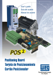
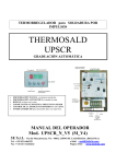
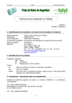
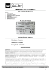
1
Owner's Guide
Guide
Owner's
Manual
Instalación
Manual del
del Usuario
Usuario ee Instalacion
RC - R/B
RQ - R/B
Leer el manual antes de usar.
Read the owner`s guide before using.
It includes guarantee certificate
Incluye certificado de garantia
Nota: las instruciones en Español empiezan en la página 17
For future reference, fill in detail of your purchase below and keep this Owne's Guide in a safe place.
Conserve el manual para futuras referencias.
Congratulations!
You made the perfect choice. You just acquired a world class
technology product. Custumed in high resistance plastic for a
longer lasting, lighter and more compact appliance. Which
also avoids rusting problems.
In this handbook, we will try to clarify all your doubts,
from the installation premises election to the basic handle
controls.
❋ CONTENTS
- Installation instructions .................................................................................................... 3
- Electrical installation ........................................................................................................ 6
- Power suply ..................................................................................................................... 8
- Operating your air conditioning applicance ..................................................................... 10
- Care and maintenance of the appliance .......................................................................... 15
- Troubleshooting Guide ................................................................................................... 16
LIST OF SYMBOLS
V - Volt
- Ground
A - Amps
- Caution
Hz - Hertz
W - Watt
- Risk of electric discharge
Kg - Kilogram
- Fuse
Oz - Ounce
in - in
- Read the manual before using.
IPXX - IP number
❋ IMPORTANT RECOMMENDATIONS
- install your air conditioning unit facing the longest side of the chosen
room.
- the ideal installation height is 1.5 m up from the floor level.
- in the event of installing a second air conditioning unit in the same
room, avoid the proximity of the two appliances.
-NEVER install your device behind curtains, furniture or dividers, because this may block the air flow of your appliance.
2
- Its better to install your appliance on the walls facing east or south,
where solar incidence is weaker.
- avoid using the cooling function of your appliance with indoors temperatures lower than 20 ºC, so ice may not be formed on the internal
heat exchanger.
- To avoid freezing of the external heat exchanger, do not use the heating
function with outdoors temperatures lower than 4ºC.
-WHENEVER you want to change from the cooling function to the warming function, or conversely, turn off the equipment and wait at least 2
minutes before turning it on again.
- If electrical energy is interrupted, immediately turn your unit off and turn
it on again just after 1 minute of the energy re-establishment. This procedure will avoid damage to the compressor due to tension variations.
- Do not use the temperature control (thermostat knob) as a switch to
turn on-off the equipment. The thermostat is the principal safety device
of its electrical circuit.
❋ INSTALLATION INSTRUCTIONS
INSTALLATION ON WALLS
The opening in the wall must allow the perfect fit of a framework to fix the appliance,
as well as to give a decorative finishing. Remember that the wooden beams of the framework must be of at least of 2.5 cm thick.
You must have in mind that the wall you choose to install the unit on must be free of
pillars, girders, pipelines and electrical ducts. According to the following table and the previous figure, chose the internal sizes of the framework:
Dimensions
A
48,5 cm
B
33,5 cm
3
C(máx)
17 cm
Build the framework, fixing the four parts. Put and fix the frame onto
the wall through 6 fixing points (3 upside and 3 downside)
INSTALLATION OF THE APPLIANCE
- to detach the metallic base of the appliance, unscrew the
safety screw located on the right hand side lateral part of the same.
- join the two lateral beams to the base with a screw in each
lateral.
screw
screw
- fix the metallic set (base and beams) to the framework,
with three screws at the base and two screws at each lateral beam
NOTE: before resuming the installation, be sure that the
slope of the base is 0.5 blister (1 cm).
- slide the appliance on the metallic base all the way and
put the safety screw located in the straight lateral part of the appliance back on.
- arrange the restraining foam to the lateral and upper parts
between the framework and the appliance to avoid air flow between the external and the internal environments.
- fix the molding on the wall to finish the installation procedure.
IMPORTANT
1) Once the installation ended, confirm the slope of the appliance is correct.
2) To reduce the cable length:
- withdraw the plastic front by unscrewing the two screws
located in the upper part of the appliance
- adjust the cable length, arrange the remaining cable on
the back of the control panel
4
- Put the plastic front back on by encasing first the lower part
and then the upper part
3) The unit comes out of factory with the cable arranged on
right hand side, but if you wish, it is possible to change it to the
other side. To do this, withdraw the plastic front, pass the cable to
the other side placing it in the lower part of the appliance, and clip
the plastic front on the labeled place.
4) Your appliance has a drainage for water to exit. Depending on the place of installation, you may use a hose connected to
the drainage net of your residence to avoid water dripping from
occurring.
drain
5) In order to keep a normal air flow through the compressor and condenser please verify that the lateral and superior openings of the appliance are turn outward and TOTALLY cleared. Otherwise, your appliance may present operation problems, with possible compressor failure. Very thick walls should be beveled outwardly.
WALL INSTALLATION USING SPECIAL CONCRETE BOXES
- follow all the previous instructions
- verify if the slope of the appliance is correct (0,5 blister - 1 cm)
- leave lateral and upper openings so the air flow within the compressor and the condenser is normal.
INSTALLATION ON WINDOWS
The installation on windows is recommended only in those
cases in which there is not any possibility of installing the appliance on walls, since it can cause vibrations and noise. But, if it is
the only place available, follow these suggestions:
5
- You must have a iron or steel reinforced structure, French
hand type or loafer, duly measured for your appliance, similar dimensions to those for wall installation
- Avoid all contact of the appliance with the glass panes,
supporting it with rubber cradles to avoid vibrations and noise.
❋ ELECTRICAL INSTALLATION
1. All the wiring will have to comply with the local and national codes of electricity and
it will have to be installed by qualified personnel.
2. There must be available an individual derived circuit with a proper outlet for the
exclusive operation of this air conditioning appliance. Consult following table with information on the capacity suggested for the cables for the derived circuit.
3. It is essential that the outlet plug that you select matches the inlet plug of the
appliance and it is within reaching distance of the installed appliance.
NOTE: The inlet cord is 39 inches ( 991 mm) long and it is attached to the lower part of the command checkerboard. DO NOT
USE a plug adapter nor an extension cord. Check Table 2 for information on types of plugs and fuses.
4. Comply with the fuse type (Table 2) indicated in the data plate of the appliance,
located above the air discharge.
5. IMPORTANT: The wires in the principal cable are arranged according to the following colour code:
Green and Yellow: Earth
Blue: Neutral
Brown: Phase
Since the colors of the wires in the principal cable of this equipment could not correspond to the terminals identifying colours in the plug, proceed in the following way:
✓ the green and yellow wire must be connected to the terminal in the plug that it is labeled
with the letter E (Earth) or by the earth symbol or coloured green and yellow.
✓ the blue wire must be connected to the terminal that it is labeled with the letter N or black
coloured.
✓ the brown wire must be connected to the terminal that it is labeled with the letter L or
coloured in red
6
MODELS
RC-067- RC-097- RQ-097- RC-081- RC-051- RC-077-
RQ-077-
COOLING ONLY COOLING ONLY HEAT PUMP COOLING ONLY COOLING ONLY COOLING ONLY
HEAT PUMP
220 V
1 PHASE - 50 HZ
POWER SUPPLY
LOCKED ROTOR CURRENT (NOTE 1)
NOMINAL
CONDITIONS *
OPERATING
ELETRIC DRAWS
COOLING
MAX.
CONDITIONS **
NOMINAL
CONDITIONS ***
HEATING
MAX.
CONDITIONS ****
OPERATING
LIMITS
MAIN
SUPPLY
DELAYED FUSES
WIRE SIZE (NOTE 2)
22,8
A
15,0
A
6,5
4,5
4,5
W
1760
2490
N/A
22,8
2490
58,6
9,9
2345
42,2
10,5
1150
4,7
2050
4,7
2050
N/A
N/A
N/A
N/A
N/A
N/A
A
4,5
4,7
W
__
2050
__
2050
A
W
__
A
mm
C
TEMP.
ROOM
o
C
OUTSIDE
o
MINIMUM
C
TEMP.
ROOM
o
C
V
N/A
2,5
2
o
__
15
A
OUTSIDE
__
N/A
W
MAXIMUM
POWER SUPPLY
115V - 50HZ - 1 PHASE
220 V
1 PHASE - 50 HZ
43
43
24 d. b.
18 w. b.
32 d. b. 32 d. b.
23 w. b. 23 w. b.
27
19
19
5
21 d. b. 21 d. b.
15 w. b. 15 w. b.
* NOMINAL CONDITIONS:
TEMPERATURE CLIMATE
220 V - 1 PHASE - 50 HZ
ISO 5151.2/T1
43
32 d. b. 32 d. b.
23 w. b. 23 w. b.
19
__
198 min-264 máx.
43
19
21 d. b. 21 d. b.
15 w. b. 15 w. b.
104 min-127 MAX.
43
24 d. b.
18 w. b.
32 d. b.
23 w. b.
27
19
5
21 d. b.
15 w. b.
__
198 min-264 máx.
*** NOMINAL CONDITIONS:
220 V - 1 PHASE - 50 HZ
AHAM RAC-1
indoor: 21,1ºC dry bulb 15ºC wet bulb
outdoor: 8,3ºC dry bulb 6,1ºC wet bulb
indoor: 27ºC dry bulb 19ºC wet bulb
outdoor: 35ºC dry bulb 24ºC wet bulb
** MAX. CONDITIONS:
198V - 1 PHASE 50 HZ
ISO 5151.2/T1
**** MAX. CONDITIONS:
198V - 1 PHASE - 50HZ
ISO 5151-2
indoor: 32ºC dry bulb 23ºC wet bulb
outdoor: 43ºC dry bulb 24ºC wet bulb
indoor: 27ºC
outdoor: 24ºC dry bulb 18ºC wet bulb
7
❋ POWER SUPPLY
Always use thermomagnetic circuit breakers together with differential circuit breakers.
The wiring shall comply according with the Standards for buildings. The nominal section of the
power supply line conductors for the electric outlet shall comply with the directives of standards
considering the nominal current, the total length until the power consumption point and the
correction factors for cabling grouping shall be verified.
Cable (mm2)
1,5
2,5
4,0
Max. Amps (A)
13
18
24
Recommended Fuse (A)
16
20
25
Values taken from the standard for cables in conduits.
IMPORTANT:
The conductors current capacity shall NEVER be less than the thermomagnetic circuit
breaker capacity.
It is not recommended to install two single-phase thermomagnetic circuit breakers in
this case.
Before plug in the equipment, check if the outlet polarity is the same as the one shown
in the equipment data sheet.
TABLE 2
RECEPTACLE AND FUSE TYPES
125
250
15
20
15
20
30
10
250
20
30
16
FUSE
SIZE
15
20
20
30
15
TIME DELAY
FUSE
(or Circuit
Breaker)
Plug
Plug
RATED VOLTS
AMPS
WALL
OUTLET
15
20
Cartridge
8
30
15
Used on
Argentina only
used
on
Europe
GROUNDING
All our units are manufactured according to the strictest safety requirements. To ensure a
complete and effective protection to the user IT IS VERY IMPORTANT AND ESSENTIAL TO
HAVE A PERFECT GROUNDING CONNECTION.
Comply with the standards about the grounding connections for this type of equipment, even
if the circuit has a differential circuit breaker for its additional protection.
Use grounding conductors similar to the power supply cables with green or yellow insulation
colors.
IN NONE CIRCUNSTANCES the unit’s plug shall be removed by cutting the power supply
cables, or a two-pin plug installed, and adapters shall not be used for plugging the unit. Use
three-pin plugs only.
NEVER connect the grounding cables to water distribution pipes. This action may cause a
risk for you as well as for other people.
THE UNIT SHALL BE PLUGGED IN ONLY AFTER YOU HAVE COMPLIED WITH ALL THESE
REQUIREMENTS.
9
❋ OPERATING YOUR AIR CONDITIONING APPLIANCE (FOR MECHANICAL UNITS ONLY)
In order to get the best performance of your air conditioning unit is necessary for you to know how to operate the
thermostat and the select functions knobs properly.
Reading the following instructions you will understand
easily how to operate your equipment.
- always turn the select functions knob clockwise
- turn the knob until desired position is reached-cooling (COOL) or heating (HEAT)
- turn the thermostat knob to the maximum position
for the chosen function
- wait for the equipment to work raising or dropping
room temperature
- once you feel comfortable with the temperature
reached turn slowly the thermostat knob in the opposite
sense, towards the minimum position, until a click is heard
- then turn the knob in the opposite sense, towards
the maximum position, just a little.
By following the previously described procedure you
will be setting the equipment to maintain the current temperature which you find ideally comfortable.
To turn off your air conditioning appliance its enough
to turn the select function knob clockwise to the (MODE)
OFF position.
10
❋ OPERATING YOUR AIR CONDITIONING APPLIANCE (FOR REMOTE CONTROL UNITS ONLY)
LIGA/DES
LIGA/DES
By pressing the
key you turn your ELECTRONIC AIR
CONDITIONING ON or OFF on the remote control. When
you turn on the equipment, the LEDs on the electronic panel will
display the information from the previous programming. When you
turn it off, all LEDs turn off as well. When you change any setting
on your remote control, the electronic panel on the inside unit will
acknowledge the change with a "BEEP". Don't worry if you try to
turn on the equipment again in less than 3 minutes and it does not
respond immediately, as this is normal procedure controlled by an
internal safety device on the compressor.
FUNÇÃO
AQUEC.
REFRIG.
VENT.
AUTO
By pressing the FUNCTION keys you can select the desired OPERATION MODE.
AQUEC.
On
(HEAT)mode the equipment will raise the selected
temperature between 18 and 29 ºC. When switching the OPAQUEC.
ERATION MODE to
(HEAT) the electronic controller will assume the last selected temperature. If this is not the
lowers
11
convenient temperature,
you can change the settings by
+
TEMP.
using the TEMP. or
keys.
AQUEC.
The
(HEAT) mode is only available on units that operate
both on cooling and heating.
The activation of this mode will be acknowledged by a red LED on
the electronic panel.
REFRIG.
On
(COOL) mode the equipment will lower the selected
temperature between 18 (64F) and 29 ºC (84F). When switching
REFRIG.
the OPERATION MODE to
, (COOL) the electronic controller
will assume the last selected temperature. If this is not the convenient
+
temperature, you can change the settings by using the
or
TEMP.
TEMP.
keys.
The
activation
of
this
mode
will
be
acknowledged
by
_
an orange LED on the electronic panel.
VENT.
On
(FAN) mode, the equipment circulates the air by using
the fan only, with no temperature change. The activation of this
mode will be acknowledged by a green LED on the electronic panel.
AUTO
The
mode keeps the temperature constant as monitored
by the electronic controller, automatically switching between COOLING and HEATING and alsochanging the speed as necessary.
When switching to AUTO the electronic controller will assume the
last selected temperature. If this is not the convenient
temperature,
+
TEMP.
you can change the settings by using the TEMP. or _ keys.
Once the electronic controller has selected an operation mode, it
won't be changed in less than 30 minutes since the last mode
switch, even if it is necessary, in order to protect the equipment.
AUTO
The
option is only available on units that operate both on
cooling and heating.
The activation of this mode will be acknowledged simultaneously
by an orange LED and a red LED on the electronic panel.
+
By pressing the TEMP keys, you perform the ppropriate
TEMPERATURE SETTING for your convenience.
+
The
key raises the temperature. The TEMP.
key
_
TEMP.
TEMP.
TEMP.
-
12
28ºC
29ºC
This option can be viewed on sis LEDs on the electronic
panel, as shown on the table on the right:
26ºC
27ºC.
!
Note:
23ºC
24ºC
25ºC
• on VENT.
(FAN) mode, the temperature LEDs will
remain off.
• the electronic panel will "BEEP" twice if the temperature range is exceeded.
22ºC
BAIXA
TEMP.
18ºC
19ºC
20ºC
ALTA
21ºC
VELOC.
TIMER
2h
5h
8h
By pressing the SPEED keys, you select the desired FAN
SPEED.
ALTA
: HIGH: by pressing this key, your air conditioner
will operate at top fan speed, regardless of temperature
mode.
BAIXA
: LOW: by pressing this key, you air conditioner
will operate at minimun fan speed, regardless of temperature mode.
By pressing the "TIMER" keys you can set the unit's operation
time until it is automatically turned off. You can choose between:
2h
: 2h - by pressing this key once, you set the equipment to
turn5h off after two hours.
: 5h - by pressing this key once, you set the equipment to
turn8h off after five hours.
: 8h - by pressing this key once, you set the equipment to
turn off after eight hours.
These settings will be acknowledged by a yellow LED on the electronic panel.
To change the equipment's operation time, just press the key for
the newly desired selection. Just bear in mind that, by performing
this change, you will be canceling the previous setting and starting
a new one, and the newly selected time will be counted from the
moment of change.
To cancel a program setting, just press the same key that was
used to activate it. The canceling of the "TIMER" mode will be
acknowledged by the turning off of the yellow LED on the electronic panel.
13
BASIC PROCEDURE
REPLACING THE REMOTE CONTROL BATTERIES
The remote control of you ELECTRONIC AIR CONDITIONING
uses two AA 1,5 V batteries. Never use old batteries or any type
other than the specified one and keep in mind that the average lasting
time of a battery is 1 (one) year. Do not replace batteries while the
equipment is on. Remove the cover of the battery chamber on the
upper part of the remote control and replace them. Test them by
turning off the equipment. If it doesn't work, remove the batteries and
repeat the operation.
EMERGENCY MODE
This mode shoud only be used to activate the equipment in case of dead batteries
on the remote control or loss or damage of the remote control.
The EMERGENCY MODE is actvated by an inside button
on the electronic panel, as shown on the left. Use a pointed object
to activate the button (A).
By pressing the button once, the equipment will operate on:
(A)
COOLING on cooling-only units
AUTO: on units that operate both on cooling heating
On both cases, the equipmente will assume 23 ºC (73F) as the convenient temperature. By pressing the button once again, the equipmente will turn off.
REMOTE CONTROL POSITIONING
• The remote control can be used at a maximum distance of 7 meters from the
equipment.
• Getting sounds:
The "BEEP" will be heard in the following cases, indicating that a command was
accepted:
- on turning on
- on turning off
- on switching modes
- on changing the temperature setting
14
DIRECTING THE AIR FLOW
You can change the direction to which the air flows by moving the adjustable baffles
on your unit. You can move them up, down, to the left or to the right.
❋ CARE AND MAINTENANCE OF THE APPLIANCE
WARNING
Before you clean the air conditioner br sure to turn off the circuit breaker or the
power main switch.
PLASTIC FRONT AND CABINET
Clean the plastic front and the cabinet with a damp flannel or a soft cloth with warm
water and neutral soap. Do not use steel sponges on the appliance because they may scratch
the surface. NEVER use detergents, alcohol or water directly on the plastic front of the appliance.
AIR FILTER
Your air conditioning appliance has a filter that retains all the impurities of the air.
The filter requires special care, to clean it follow de instructions:
- before to start cleaning it, turn off it the appliance
- to remove it, raise it using the two handles located under the air exhaust of your
appliance.
- vacuum clean or wash it with luke warm water and neutral soap. Flap and let dry
well before putting it back on the appliance.
- clean the filter every two weeks
IMPORTANT
- a dirty air filter means a reduced capacity of your air conditioning
unit and an energy consumption increase.
- NEVER operate your appliance without the air filter, since the dust
and other solid particles may penetrate the components, and thus
damaging your appliance.
- for the models with heaters, it is advisable to turn on the heating
once a month.
- if the device is not going to be used in long time, turn off the main
switch and unplug it.
CABLES
Verify periodically if the power supply cable or register are damaged, for safety do not use the
unit. Before using the equipment again the power supply cable must be replaced by qualified
personnel, manufacturer or specialized technical service.
15
❋ TROUBLESHOOTING GUIDE
Before calling a technician, see how to proceed if your air conditioning device presents some of the following described symptoms.
TROUBLE
The unit does not work
The unit does not
work properly
PROBABLE CAUSE
1) The main switch turned off
2) Appliance is unplugged
outlet
3) Energy failure
SOLUTIONS
1) Turn main switch back on
2)Plug your unit to the electrical
1) Dirty air filter
2) Air flow is blocked
1) Clean the air fliter
2) Remove objects interfering with
the air flow (curtains, furniture, ...)
3) Be sure all the doors and
windows are well closed
4) Supress any heat source
5) Place the thermostat knob
correctly according to this
handbook
6) Chose a larger model to fulfill
your needs
3) The room is not well closed
4) There is some heat source
5) Thermostat knob is not
correctly placed
6)The device is under
dimensioned for the premises
Frozen internal
heat exchanger
1) Unproper air flow
1) Move objects that may be
blocking the air flow
2) Clean the air filter
2) Dirty air filter
Water leaks within
the room
3)Wait for the energy to come back
1) Clogged drainage
2) Improper installation
1) Unclogged the drainage
2)Install the unit properly according
to this handbook
16
¡Felicitaciones!
Usted acaba de hacer una excelente elección. Usted adquirió
un producto con tecnología mundial, producido en plástico de
alta resistencia que permite más durabilidad, elimina problemas
de oxidación y hace con que el aparato sea más liviano y
compacto.
En este manual, procuramos aclarar todas sus dudas, desde
el lugar elegido para la instalación hasta el simple manejo de
los controles.
❋ ÍNDICE
- Instrucciones para instalación ........................................................................................ 18
- Instalación eléctrica ....................................................................................................... 21
- Alimentación eléctrica .................................................................................................... 23
- Operando su aparato de aire acondicionado ................................................................... 25
- Conservación y mantenimiento del aparato .................................................................... 31
- Soluciones prácticas ...................................................................................................... 32
LA LISTA DE SÍMBOLOS
V - Volt
A - Ampere
Hz - Hertz
W - Watt
Kg - Kilogramo
Oz - Onza
in - Pulgada
IPXX - Número IP
- Tierra
- Precaución
- Riesgo de choque eléctrico
- Fusible
- Leer el manual antes de usar.
❋ RECOMENDACIONES IMPORTANTES
- instale su aire acondicionado de frente para el una mayor dimensión
del ambiente escogido.
- la altura ideal para la instalación es de 1,5m arriba del nivel del
piso.
- en la instalación de un segundo aire acondicionado en un mismo
ambiente, evite la proximidad de los dos aparatos.
- JAMÁS obstruya la circulación de aire de su aparato, instalándolo
atrás de cortinas, muebles o poneles divisorias.
17
- procure instalar su aparato en las paredes orientadas hacia el este o
el sur, donde la incidencia solar es más débil.
- evite el uso de este aparato en la operación de enfriamiento con
temperaturas internas inferiores a 20 ºC para que no ocurra formación
de hielo en el dispositivo de calor interno.
- evite el uso de este aparato en la operación calentamiento con
temperaturas externas inferiores a 4ºC, pues podrá ocurrir el
congelamiento del dispositivo de calor externo.
- SIEMPRE que quiera cambiar de la operación enfriamiento para
calentamiento, o viceversa, apague el equipo y aguarde 2 minutos
antes de encenderlo nuevamente.
- si la energía eléctrica fue interrumpida, apague inmediatamente su
aire acondicionado y solamente vuelva a encenderlo 1 minuto después
del restablecimiento. Ese procedimiento evitará variaciones de tensión
que pueden ocasionar que el compresor se queme.
- no utilice el interruptor como llave de encendido-apagado del equipo.
El interruptor es el principal dispositivo de seguridad de su circuito
eléctrico.
❋ INSTRUCCIONES PARA INSTALACIÓN
INSTALACIÓN EN PAREDES
La abertura en la pared debe permitir el encaje perfecto de un marco para fines de
acabado, bien como para fijar el aparato. Conviene recordar que el espesor de la madera
del marco debe ser de por lo menos de 2,5 cm.
Usted debe tener mucha atención cuando escoja el local en la pared. Él debe estar
libre de pilares, vigas, tuberías y electroductos. De acuerdo con la tabla a seguir y la figura
anterior, vea los tamaños internos del marco:
Tamaño
A
48,5 cm
B
33,5 cm
C (máx.)
17 cm
18
Arme el marco, fijando las cuatro partes. Coloque y fíjelo en la
pared a través de los 6 puntos de fijación (3 arriba y 3 abajo).
INSTALACIÓN DEL APARATO
- para desprender la base metálica del aparato, retire el
tornillo de seguridad localizado en la parte lateral derecha del
mismo.
- prenda los dos tirantes laterales en la base con un tornillo
en cada lateral.
tornillo
tornillo
traba
moldura
tornillo
de seguridad
10 mm
inclinación
- fije el conjunto metálico (base y tirantes) en el marco,
prendiéndolo y fijándolo con los tres tornillos de la parte inferior y
los dos laterales
NOTA: antes de continuar la instalación, observe si la
inclinación de la base es de 0,5 ampolla (1 cm).
- deslice el aparato sobre la base metálica hasta el fondo y
coloque el tornillo de seguridad localizado en la parte lateral
derecha del aparato
- coloque la espuma de vedado en las laterales y parte superior entre el marco y el aparato para evitar el pasaje de aire del
ambiente externo para el interno y viceversa
- fije la moldura en la pared para dar el acabado en la
instalación.
IMPORTANTE
1) Terminada la instalación, observe si la inclinación del
aparato está correcta.
2) Para disminuir la largura del cable:
- retire la frente plástica a través de los dos tornillos
localizados en la parte superior del aparato
- ajuste el tamaño del cable, colocando la parte excedente
atrás del panel de control
- Coloque nuevamente la frente plástica encajando primero
la parte inferior de la misma
19
3) El cable de su aparato sale de fábrica colocando al lado derecho,
pero si usted lo desea, es posible cambiarlo de lado. Para esto,
retire la frente plástica, pase el cable para el otro lado
acomodándolo en la parte inferior del aparato, recorte la frente
plástica en el local marcado.
4) Su aparato contiene un dreno para salida de agua.
Dependiendo del local instalado, use una manguera conectada a
la red de drenaje de su residencia evitando que ocurra goteo de
agua en locales no apropiados.
dreno
interna
pared
externa
abertura 92cm
5) Para que el movimiento del aire en el compresor y
condensador se procese normalmente, verifique atentamente si
las aberturas laterales y superior del aparato están volcadas para
fuera y TOTALMENTE desobstruidas. Caso contrario, su aparato
corre el riesgo de presentar problemas en el funcionamiento, con
posibilidad de que el compresor se queme. Paredes muy espesas
deben ser chaflanadas exteriormente.
INSTALACIONES EN PAREDES CON EL USO DE CAJAS ESPECIALES DE CONCRETO
- siga todas as instrucciones anteriores
- verifique si la inclinación del aparato está correcta (0,5 ampolla 1cm)
- deje aberturas laterales y superior para que el movimiento del
aire en el compresor y en el condensador se procese normalmente.
INSTALACIÓN EN VENTANAS
La instalación en ventanas sólo se recomienda en casos
en los cuales no exista la posibilidad de instalar el aparato en
paredes, pues puede provocar vibraciones y ruidos. Pero, si es el
único local disponible para la instalación, siga algunas sugerencias:
- disponga de una estructura reforzada en fierro o acero, tipo mano
francesa o cantonera, debidamente medida para su aparato para
que se la fije en le pared
- intente evitar al máximo el contacto del aparato con los
vidrios, apoyándolo con cuñas de goma para evitar vibraciones y
ruido.
20
❋ INSTALACIÓN ELÉCTRICA
1.Todo el alambrado deberá cumplir con las normas locales y nacionales de electricidad
y deberá ser instalado por electricistas calificados y con experiencia.
2.Deberá haber disponible un circuito independiente con su enchufe destinado
exclusivamente para la operación de este aparato de aire acondicionado. Consulte la siguiente
tabla con informaciones sobre la capacidad sugerida para los cables del circuito
independiente.
3.Es esencial que el enchufe que usted seleccione corresponda al enchufe de
alimentación del aparato y esté al alcance del aparato instalado.
NOTA: El cordón de alimentación mide __ pulgadas ( ____ mm)
d e largo y se extiende desde la parte inferior del tablero de mando.
NO USE un adaptador de enchufe ni un cordón de extensión.
Consulte la Tabla 2 para tipos de enchufes e información de
fusibles.
4.Cumpla con las indicaciones de fusible (Tabla 2) indicadas en la placa de datos del
aparato, localizado encima de la sección de salida de aire.
5.IMPORTANTE: Los alambres en este cable principal tienen colores de acuerdo con
el siguiente código:
Verde y Amarillo: Tierra
Azul: Neutro
Marrón: Fase
Como los colores de los alambres en el cable principal de este equipo pueden no
corresponder a las marcas de colores identificando los terminales en su enchufe, proceda
de la siguiente manera:
✓ el alambre que está pintado de verde y amarillo debe ser conectado al terminal en el
enchufe que está marcado con la letra E (Earth/ Tierra) o por el símbolo tierra o pintado
de verde y amarillo.
✓ el alambre que está pintado de azul debe estar conectado al terminal que está
marcado con la letra N o pintado de negro.
✓ el alambre que está pintado de marrón debe estar conectado al terminal que está
marcado con la letra L o pintado de rojo.
21
MODELOS
RC-067- RC-097- RQ-097-
ALIMENTACIÓN ELÉCTRICA
220 V
1 PHASE - 50 HZ
TRACCIÓN DE POTENCIA DE
FUNCIONAMIENTO
CORRIENTE DE ARRANQUE (NOTA 1)
CONDIC.
NOMINALES *
ENFRIAMIENTO
MAX.
CODICIONES **
CONDIC.
NOMINALES ***
CALEFACCIÓN
MAX.
CODICIONES ****
FUSIBLES RETARDADO
LÍMITES DE
FUNCIONAMIENTO
CALIBRE DE LOS CONDUCTORES (NOTA 2)
TEMPERATURA
EXTERIOR
MÁXIMA
INTERIOR
MINIMUM
EXTERIOR
TEMP.
INTERIOR
ALIMENTACIÓN ELÉCTRICA
FRÍO SOLO
FRÍO SOLO BOMBA DE CALOR
15,0
A
RC-081- RC-051- RC-077- RQ-077FRÍO SOLO
FRÍO SOLO
115V - 50HZ - 1 PHASE
22,8
FRÍO SOLO
BOMBA DE CALOR
220 V
1 PHASE - 50 HZ
22,8
42,2
10,5
1150
4,7
2050
4,7
2050
N/A
N/A
N/A
__
A
6,5
4,5
4,5
W
1760
2490
2490
58,6
9,9
2345
N/A
N/A
N/A
N/A
4,5
4,7
__
2050
2050
A
W
A
W
__
A
W
mm
o
C
o
C
o
C
V
N/A
2,5
2
C
__
15
A
o
__
N/A
43
43
24 d. b.
18 w. b.
32 d. b. 32 d. b.
23 w. b. 23 w. b.
19
27
19
__
198 min-264 máx.
43
43
24 d. b.
18 w. b.
32 d. b. 32 d. b. 32 d. b.
23 w. b. 23 w. b. 23 w. b.
19
5
21 d. b. 21 d. b.
15 w. b. 15 w. b.
43
19
19
21 d. b. 21 d. b. 21 d. b.
15 w. b. 15 w. b. 15 w. b.
104 min-127 MAX.
27
5
__
198 min-264 máx.
(*) Condiciones Nominales
(***) Condiciones Nominales
CLIMAS TEMPLADOS
220 V - 1 fase - 50Hz
220 V – 1 fase – 50Hz
AHAM RAC-1
ISO 5152.1/T1
interior: 21,1ºC bulbo seco 15ºC bulbo húmedo
exterior: 8,3ºC bulbo seco 6,1ºC bulbo húmedo
interior: 27 ºC bulbo seco 19 ºC bulbo húmedo
exterior: 35 ºC bulbo seco 24 ºC bulbo húmedo
(**)
Condiciones Máx.
(****)Condiciones Máx.
CLIMAS TEMPLADOS
198V - 1 fase - 50Hz
198V – 1 fase – 50Hz
ISO 5151-2
ISO 5152.1/T1
interior: 27ºC
interior: 32 ºC bulbo seco 23 ºC bulbo húmedo
exterior: 24ºC bulbo seco 18ºC bulbo húmedo
exterior: 43 ºC bulbo seco 24 ºC bulbo húmedo
22
❋ ALIMENTACIÓN ELÉCTRICA
Utilice siempre interruptores termomagnéticos en conjunto con interruptores diferenciales.
La instalación debe realizarse acorde a lo establecido por la Reglamentación para la Ejecución
de Instalaciones Eléctricas en Inmuebles. La sección nominal de los conductores de la línea
de alimentación hasta el tomacorriente deben obedecer a lo indicado por las normas,
considerándose la corriente nominal, la distancia al punto de consumo y los factores de
corrección para agrupación de cables.
Cable (mm2)
1,5
2,5
4,0
Corriente Máxima (A)
13
18
24
Interruptor Termomagnetico
16
20
25
Valores extraídos de la norma para cables instalados en cañerías.
IMPORTANTE:
NUNCA utilice conductores cuya capacidad sea inferior a la capacidad nominal del interruptor termomagnético.
No es recomendable el uso de dos interruptores termomagnéticos monopolares para esta
aplicación.
Antes de conectar el equipo cerciórese que la polaridad de su tomacorriente sea igual a la
indicada en la ficha eléctrica del equipo.
23
INSTALACIÓN DE TIERRA
Todas nuestras unidades están fabricadas con las más estrictas normas de seguridad. Para
que la protección total del usuario sea efectiva ES IMPRESCINDIBLE PROVEER UNA
PERFECTA CONEXION A TIERRA.
Cumpla con el requerimiento legal que obliga a realizar la conexión a tierra de este tipo de
aparatos, aún contando con la protección adicional de un disyuntor diferencial.
Utilice conductores de tierra de sección igual a los cables de alimentación con aislación
color verde/amarillo..
BAJO NINGUNA CIRCUNSTANCIA puede cambiarse la ficha de la unidad cortando el cable
de alimentación, ni utilizarse tomacorriente de 2 bornes o adaptadores para la conexión a la
red. Utilice solamente tomacorriente con 3 bornes.
NUNCA asegure la continuidad de la toma de tierra con la cañería de la red de agua; ésto
coloca en riesgo su seguridad o la de terceros.
SI CUMPLIO CON TODOS ESTOS REQUISITOS, CONECTE LA UNIDAD
TABLA 2
TIPOS DE TOMACORRIENTES Y FUSIBLES
VOLTIOS
NOMINALES
AMPERIOS
125
250
250
15
20
15
20
30
10
20
30
16
15
20
15
20
30
15
20
30
15
TOMACORRIENTE
CAPACIDAD
DE FUSIBLE
FUSIBLE CON
RETARDO
(o interruptor
de Circuito)
Enchufe Enchufe
Cartucho
24
Para aplicaciones en la
Argentina solamente
Aplicacion
en la
Europe
❋ OPERANDO SU APARATO DE AIRE ACONDICIONADO (SÓLO PARA LOS APARATOS MECANICOS)
Para que usted obtenga el mejor desempeño de su
aparato de aire acondicionado es necesario saber colocar
correctamente el botón del termostato y el botón del selector
de operaciones.
A través de la lectura de las instrucciones descritas
abajo usted entenderá fácilmente cómo operar su equipo.
- gire siempre el botón selector de operaciones
(MODE) en el sentido horario
- coloque el mismo en la operación deseadaenfriamiento (COOL) o calentamiento (HEAT).
- gire el botón del termostato colocándolo en su
posición máxima para la operación escogida
- aguarde que el equipo climatice su ambiente
- al sentir que la temperatura en el ambiente alcanzó
la temperatura de comodidad deseada, diríjase hasta el equipo y gire lentamente el botón del termostato en dirección a su
posición mínima hasta que usted escuche un pequeño “click”
- ejecute entonces un leve giro en el sentido contrario
Para apagar su aparato de aire acondicionado basta
girar el botón del selector de operaciones en el sentido horario
basta colocar el mesmo em apagar ( MODE OFF)
25
❋ OPERANDO SU APARATO DE AIRE ACONDICIONADO (SÓLO PARA LOS APARATOS ELECTRÓNICOS)
LIGA/DES
LIGA/DES
Presione la tecla
usted ENCIENDE Y APAGA su
AIRE ACONDICIONADO ELETRÓNICO a través del control
remoto. Al enceder el equipo aparecerá en el panel electrónico, a
través de los LED's, la totalidad de las informaciones contenidas
en la programación anterior. Al pagarlo, todos los LED's se
apagarán. Al cambiar cualquier parámetro a través de su control
remoto el panel electrónico localizado en la unidad interna
responderá al comando emitiendo un "BEEP" indicando que recibió
la información. No se extrañe si, al intentar encender nuevamente
antes de que hayan pasado 3 minutos, no hay respuesta inmediata
del equipo, pues se trata de un procedimiento normal operado
por dispositivo interno de protección del compresor.
26
FUNÇÃO
AQUEC.
REFRIG.
VENT.
AUTO
Presionando las teclas del grupo FUNCIÓN (FUNÇÃO) usted
opta por la OPERACIÓN DESEADA.
AQUEC.
En la función
(CALENTAMIENTO) el equipo, cuando
está en funcionamiento eleva la temperatura que usted ha
establecido entre 18 ºC (64F) y 29ºC (84F). Al cambiar la
AQUEC.
OPERACIÓN DESEADA por
(CALIENTAMIENTO) el
controlador electrónico asumirá la última temperatura que
usted haya establecido. Caso esta no sea la temperatura
ideal para su comodidad, proceda al ajuste
de la
+
TEMP.
temperatura. Para tanto, utilice las teclas TEMP. o - .
AQUEC.
La opción
(CALIENTAMIENTO) solamente está
disponible en unidades que operen en enfriamiento y
calentamiento.
La confirmación del accionamiento de esta función se dará
a través del LED rojo en el panel electrónico.
REFRIG.
En la función
(ENFRIAMIENTO) el equipo, cuando
está en funcionamiento, reduce la temperatura que usted ha
establecido entre 18ºC (64F) y 29ºC (84F). Al cambiar la
REFRIG.
OPERACIÓN DESEADA por
(ENFRIAMIENTO) el
controlador electrónico asumirá la última temperatura que
usted haya establecido. Caso esta no sea la temperatura ideal
para su comodidad, proceda
al
ajuste de temperatura. Pra
+
TEMP.
tanto, utilice las teclas TEMP. o _ . La confirmación del
accionamiento de estas funciones se dará a través del LED
anaranjado en el panel electrónico.
VENT.
En la función
(VENTILACIÓN) el equipo fuerza la
circulación del aire del ambiente permaneciendo en
funcionamiento apenas el ventilador del mismo, sin
alteración de la temperatura. La confirmación del
accionamiento de esta función se dará a través del LED
verde en el panel electrónico.
AUTO
La función
consiste en mantener la temperatura del
ambiente acondicionado siempre constante a través de
monitoreo por el controlador electrónico de la unidad dando
al mismo libertad de opción entre las funciones de
ENFRIAMIENTO o CALENTAMIENTO, buscando también
la velocidad de funcionamiento más adecuada para tal. Al
AUTO
cambiar para la función
el controlador electrónico
27
+
TEMP.
-
!
Presionando las teclas del grupo TEMP. usted ejecuta el
AJUSTE DE TEMPERATURA
propio para su comodidad.
+
A través de la tecla TEMP usted está elevando la temperatura
TEMP.
del ambiente. A través de la tecla _ usted está reduciendo
la temperatura del ambiente.
Esta opción está visible en el panel electrónico a través de
6 LED's, conforme la tabla al lado:
18ºC
19ºC
20ºC
21ºC
22ºC
23ºC
24ºC
25ºC
26ºC 27ºC.
28ºC
29ºC
TEMP.
asumirá la última temperatura que usted haya establecido.
Caso no sea la temperatura ideal para su comodidad,
proceda al ajuste de la temperatura. Para tanto utilice las
+
TEMP.
teclas TEMP o _
.
Después que el controlador electrónico defina por una de
las funciones, aunque se verifique la necesidad de cambio
de la misma, esta sólo se efectuará 30 minutos después
de la última alteración, a fin de proteger el equipo. La opción
AUTO
solamente está disponible en unidades que operen
en enfiamiento y calentamiento. La confirmación del
accionamiento de esta función se dará a través de los LEDs
anaranjado y rojo actuando simultáneamente en el panel
electrónico.
VELOC.
Observación:
VENT.
• Operando en la función
(VENTILACIÓN) los LED's
referentes a temperatura permanecerán apagados.
• El panel electrónico emitirá "BEEPs" caso el range de
temperatura sea traspasada.
TEMP.
ALTA
BAIXA
Presionando las teclas del grupo VELOCIDADE (SPEED)
Usted selecciona la VELOCIDAD DE VENTILACIÓN
deseada.
ALTA
: ALTA: presionando una vez esta tecla, su
acondicionador de aire operará en la velocidad máxima de
insuflación
de aire, independiente e la función escogida.
BAIXA
: BAJA: presionando una vez esta tecla, su
acondicionador de aire operará en la velocidad mínima de
insuflación de aire, independiente e la función escogida.
Presionando las teclas del grupo TIEMPO (TIMER) usted
define el tiempo de funcionamiento de la unidad hasta que
esta se apague automáticamente. Usted puede optar por:
28
TIMER
2h
5h
8h
2h
: 2h - presionando una vez esta tecla, usted estará
informando al equipo que este deberá apagarse al final de
dos horas de funcionamiento.
5h
: 5h - presionado una vez esta tecla, usted estará
informando al equipo que este deberá apagarse al final de
cinco horas de funcionamiento.
8h
: 8h - presionando una vez esta tecla, usted estará
informando al equipo que este deberá apagarse al final de
ocho horas de funcionamiento.
La confirmación del accionamiento de esta función, se dará a
través del LED amarillo en el panel electrónico.
Para alterar el tiempo de funcionamiento del equipo, basta
presionar la tecla del nuevo horario desado. Recuerde que,
haciendo esta alteración, usted estará cancelando la programación
anterior e iniciando una nueva, o sea, el nuevo tiempo de
funcionamiento se contará a partir del momento de la altración.
Para cancelar un comando de programación, basta presionar una
vez la misma tecla usada para accionarlo. La confirmación del
cancelamiento de la función TIMER se dará cuando el LED amarillo
del panel electrónico se apague.
PROCEDIMIENTOS BÁSICOS
SUSTITUYENDO LAS PILAS DEL CONTROL REMOTO
El control remoto de su AIRE ACONDICIONADO
ELECTRÓNICO utiliza 2 (dos) pilas tipo AA 1,5V. Jamás utilice
pilas usadas u otras que no las especifiadas y recuerde que la
duración promedio de una pila para esta aplicación es de
aproximadamente 1(un) año. No realice la sustitución de las pilas
con el equipo encendido.
Remueva las pilas en la parte superior del control remoto y
opere la sustituición de las mismas. Haga la prueba encendiendo
el aparato. En el caso de que no funciones retire las pilas y reinicie
toda la operación.
29
MODO EMERGENCIA
Este modo solamente debe usarse para accionar el equipo en caso de que las pilas
del control remoto estén descargadas o entonces en caso de pérdida o daño del mismo.
EL MODO EMERGENCIA se acciona a través de un botón
interno localizado en el panel electrónico, conforme la figura anexa.
Para accionar el botón, utilice un objeto puntiagudo.
(A)
Apretando el botón (A) 1 (una) vez el equipo pasará a
funcionar en la función:
REFRIG.: en los aparatos que operan apenas en
enfriamiento
AUTO: en los aparatos que operan en calentamiento y
enfriamiento
En ambas situaciones el equipo asumirá como temperatura ideal para funcionamiento
237ºC (73F). Apretando el botón nuevamente 1 (una vez), el equipo se apagará.
POSICIÓN DEL CONTROL REMOTO
• El control remoto puede ser usado a una distancia máxima de hasta 7 metros del
equipo.
• Recibiendo señales sonoras:
La señal de "BEEP" del equipo podrá ser escuchada en los siguientes casos,
indicando la recepción de la señal:
- al ecender
- al apagar
- al cambiar de operación
- al proceder a un nuevo ajuste de temperatura
30
DIRECCIÓN DEL AIRE
Su aparato de aire acondicionado permite dirigir el aire para arriba, para abajo, para la
izquierda o para la derecha a través de los deflectores regulables.
❋ CONSERVACIÓN Y MANTENIMIENTO DEL APARATO
ADVERTÊNCIA
Antes de limpiar el acondiconador de aire, apague el disyuntor o el interruptor principal.
FRENTE PLÁSTICA Y GABINETE
Haga una limpieza periódica en la frente plástica y en el gabinete con una franela o un
pedazo de tela suave mojada con agua tibia y jabón neutro. No utilice esponjas de acero en la
limpieza de su aparato pues ellas arañan el mismo. JAMÁS use detergentes, alcohol o agua
directamente sobre la frente plástica del aparato.
FILTRO DE AIRE
Su aparato de aire acondicionado tiene un filtro que retiene las impurezas del aire del
ambiente. Él requiere cuidados especiales para limpieza, como sigue:
- antes de limpiarlo apague el aparato
- para retirarlo, levántelo con las agarraderas localizadas debajo de la salida de aire de
su aparato.
- límpielo con aspirador de polvo o con agua tibia y jabón neutro. Sacuda y seque bien
antes de colocarlo nuevamente en el aparato.
- esta limpieza debe hacerse quincenalmente
IMPORTANTE
- filtro de aire obstruido representa la reducción de la capacidad de su aire
acondicionado y el aumento del consumo de energía.
- NUNCA opere su aparato sin el filtro de aire, pues el polvo e impurezas se
instalarán en otros componentes, dañando su aparato.
- es aconsejable encender los aparatos modelo caliente/frío en el calentamiento
por algunos minutos de 30 en 30 días.
- si no se utiliza su aire acondicionado por un período de tiempo más largo,
desconecte o enchufe y apague el interruptor.
CABLES
Verifique periódicamente si el cable electrico de alimentacion y su ficha no se encuentren
dañado, por seguridad no utilice el aparato. Antes de volver a utilizar el equipo el cable de
alimentacion debe ser reemplazado por personal calificado, fabricante o servicio técnico
especializado.
31
❋ SOLUCIONES PRÁCTICAS
Antes de llamar un técnico, vea cómo proceder si su aire acondicionado presenta
alguno de los síntomas abajo descritos.
PROBLEMA
El aire
acondicionado
no funciona
Equipo no
acondiciona
adecuadamente
PROBABLES CAUSAS
1) interruptor apagado
2) cable de alimentación
desconectado de la redeléctrica
3) falta de energía en la red
1) filtro de aire sucio
2) obstrucción del flujo de aire
3) ambiente abierto
4) existencia de alguna fuente de
calor en el ambiente
5) botón del termostato mal
colocado
6) el aparato no fue
adecuadamente medido para
el ambiente
Dispositivo de
calor interno
congelado
1) circulación ineficaz del aire
Flujo de agua
para dentro
del ambiente
1) drenage tapado
2) instalación incorrecta
2) filtro de aire sucio
SOLUCIONES
1) encienda nuevamente el
interruptor
2) conecte el cable de
alimentación en el enchufe
3) aguarde el restablecimiento de
la energía
1) limpie el filtro de aire
2) remueva las obstrucciones
(cortinas, sofás, ...)
3) cierre las puertas o ventanas
abiertas
4) elimine la fuente de calor del
ambiente
5) ajuste correctamente la
posición del termostato
conforme instrucciones de este
manual
6) defina adecuadamente, de
nuevo, el modelo del aparato
para el ambiente
1) desobstruya la frente del
aparato
2) limpie o filtro de aire
1) desobstruya el drenage
2) corrija la instalación conforme
instrucciones de este manual
32
SCHEMATIC
REFRIGERATION
SYSTEM/SISTEMA
Cooling only unit / Unidades sólo
refrigeración
DE
REFRIGERACIÓN
1. Outdoor unit coil
Fico
2. Indoor unit coil
Fico
Gas
Fico
Liquid + Gas
Líquido + Gas
Liquid
Líquido
Refrigerante charge control
Control de la carga refrigerante
Heat pump unit/Unidad de bomba de calor
1. Outdoor unit coil
Serpentín unidad exterior
COOLING CYCLE
Refrigerant charge control
CICLO REFRIGERACION
Control de la carga refrigerante
2. Indoor unit coil
Serpentín unidad interior
Gas
Gas
Liquid + Gas
Líquido + Gas
HEATING CYCLE
Refrigerant charge control
CICLO CALEFFACION
Control de la carga refrigerante
Liquid
Líquido
33
WIRING DIAGRAM / CONEXIONES ELECTRICAS
MECHANICAL UNITS / APARATOS MECANICOS
RC MODELS / MODELOS
RQ MODELS / MODELOS
34
WIRING DIAGRAM / CONEXIONES ELECTRICAS
ELETRONIC UNITS / APARATOS ELETRÓNICOS
RC MODELS / MODELOS
RQ MODELS / MODELOS
35
36
37
38
GARANTIA
Garantia válida solamente para el territorio de la República Argentina
39
Av. Remedios de Escalada 2900
B 1822AAP - V. Alsina - Lanús O.
Buenos Aires - Argentina
TEL.: (011) 4229 - 5085
WE AREN'T COMFORTABLE UNTIL YOU ARE
NO ESTAMOS A GUSTO HASTA QUE USTED LO ESTÉ
Manufacturer reserves the right to discontinue, or change at any time, specifications or designs without notice and wihout incurring obligations.
El fabricante se reserva el derecho de descontinuar o cambiar en cualquer momento, las especificaciones o disños sin informar o sin incurrir en obrigaciones.
256.08.483 - A - 08/01