1
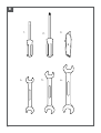
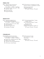
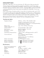
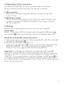
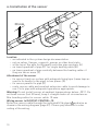
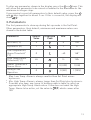
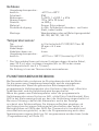
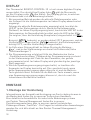
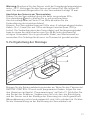
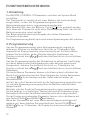
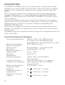
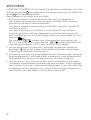
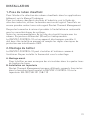
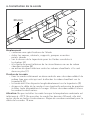
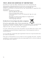
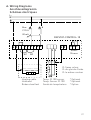
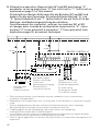
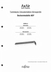
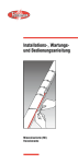
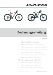
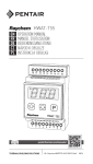
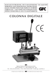
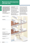
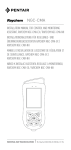
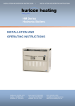
RAYSTAT-CONTROL-10 Control thermostat Thermostat Thermostat de contrôle Thermal Building Solutions ML-RaychemRAYSTATCONTROL10-IM-INST195 Rev8 English Table of contents ��������������������������������������������������������������������������������������� 2 Description & Technical data ��������������������������������������������������������������������� 6 Functional description ������������������������������������������������������������������������������� 7 Display �������������������������������������������������������������������������������������������������������� 7 Installation description ������������������������������������������������������������������������������ 8 Operational description ��������������������������������������������������������������������������� 11 Testing, commissioning and maintenance ���������������������������������������������� 14 Wiring diagrams �������������������������������������������������������������������������������������� 37 Commissioning sheet ������������������������������������������������������������������������������ 39 Deutsch Inhaltsverzeichnis ������������������������������������������������������������������������������������� 2 Beschreibung & technische Daten ���������������������������������������������������������� 16 Funktionsbeschreibung ��������������������������������������������������������������������������� 17 Display ������������������������������������������������������������������������������������������������������ 18 Montage ��������������������������������������������������������������������������������������������������� 18 Programmierung ������������������������������������������������������������������������������������� 22 Test, Inbetriebnahme und Wartung ��������������������������������������������������������� 25 Anschlussdiagramme ������������������������������������������������������������������������������ 37 Inbetriebnahmeprotokoll ������������������������������������������������������������������������� 39 FRANçAIS Table des matières ������������������������������������������������������������������������������������ 2 Description & caractéristiques techniques ��������������������������������������������� 26 Fonctionnement ��������������������������������������������������������������������������������������� 27 Afficheur ��������������������������������������������������������������������������������������������������� 28 Installation ����������������������������������������������������������������������������������������������� 29 Paramétrage �������������������������������������������������������������������������������������������� 33 Test, mise en service et entretien ����������������������������������������������������������� 36 Schémas électriques ������������������������������������������������������������������������������� 37 Fiche de mise en service ������������������������������������������������������������������������� 39 2 A 1 9a 9b V DE 8 3 2 4 5 6 7 3 B 1. 4. 4 2. 5. 3. 6. English A1.Thermostat enclosure 2, 3, 4, 5. Cable entries (2 x M25, 1 x M20, 1 x M16) 6.Temperature sensor Pt 100 7.Sensor cable 8.Push buttons 9.Digital display DEutsch A1.Thermostatgehäuse 2, 3, 4, 5. Einführungen (2 x M25, 1 x M20, 1 x M16) 6.Temperatursensor Pt 100 7.Sensorkabel 8.Steuerungstasten 9.Digitales Display français A 1.Boîtier du thermostat 2, 3, 4, 5. Entrées de câbles (2 x M25, 1 x M20, 1 x M16) 6.Sonde de température Pt 100 7.Câble de la sonde 8.Touches de programmation 9.Afficheur numérique B1.Terminal screwdriver 3 mm 2.Posi-drive screwdriver 5 mm 3.Trimming knife 4, 5, 6. Spanners (27 mm, 24 mm, 19 mm) B1.Schraubendreher 3 mm, Längsschlitz 2.Schraubendreher 5 mm, Kreuzschlitz 3.Kabelmesser 4, 5, 6. Schraubenschlüssel (27 mm, 24 mm, 19 mm) B1.Tournevis 3 mm 2.Tournevis 5 mm 3.Cutter 4, 5, 6. Clés (27 mm, 24 mm, 19 mm) 5 Description RAYSTAT-CONTROL-10 is an electronic Pt 100 control thermostat with display, advanced alarm facilities and the capability of switching large currents (25 A). The RAYSTAT-CONTROL-10 is designed to control Pentair Thermal Controls heating cable systems. Heating cable can be controlled (switched ON/OFF) either directly by the RAYSTAT-CONTROL-10 or via a contactor. Direct switching of heating cables is possible for heating loads up to 25 A. For heating loads greater than 25 A indirect switching via a suitably rated contactor controlled by a RAYSTAT-CONTROL-10 is necessary. Installation and all wiring must be in accordance with applicable regulations. The device must be installed in non hazardous areas only. Pentair Thermal Management offers other controls for use in hazardous areas. Technical data Supply voltage:230 Vac. +10%/–10%, 50/60 Hz (6V leakproof maintenance-free nonrechargeable battery incl. for programming without power supply) Main relay: max. 25 A, 250 Vac. Resistive Heater operation on sensor error: programmable: ON or OFF Hysteresis: programmable: 1K to 5K Set point T range: 0°C to + 150°C Accuracy: ±0,5 K at 5°C Operating Temperature:–30°C (–20°C, VDE approved) to +40°C ambient User interface: 4 x 7 segment digital display 4 push buttons alarm relay, max. 2 A, 250 Vac. (Potential free) Power terminals: 3 x 0,75 mm² to 4 mm² Alarm terminals: (3 + ) x 0,75 mm² to 2,5 mm² Sensor terminals: (3 + ) x 0,75 mm² to 2,5 mm² Heater terminals: (2 + ) x 0,75 mm² to 4 mm² Enclosure Exposure Temperature: Ingress Protection: Entries: Size: Weight: Material: Lid fixing: 6 –40°C to +80°C IP 65 2 x M25, 1 x M20, 1 x M16 120 x 160 x 90 (mm) approx. 800 gr. polycarbonate 4 captive screws Mounting:on a wall or directly on the pipe using support brackets, SB-100 / SB-101 / SB-110 T sensor / Type: 3-wire Pt 100 according to IEC Class B Sensor head: 50 mm x ∅ 5 mm Cable length: 3 m* Cable diameter: 4 mm Cable exposure T:–40°C to +150°C (+215°C intermittent 1000h) * The sensor cable can be extended with a 3-core shielded cable of 20 Ω max. per conductor (e.g. up to 150 m with a 3x1.5 mm² cable). The shield shall be earthed on the controller side only. Functional description During normal operation, the display alternates between the measured temperature and the set point temperature. When the measured pipe temperature exceeds the programmed setpoint value plus hysteresis, the switching contact opens and the heating cable is switched off. When the measured pipe temperature falls below the setpoint value minus hysteresis, the switching contact closes. A LED in the display indicates that the heating cable is switched on. In the event of an error, the alarm relay switches and an error code shows on the display. It is possible to program the status of the heating cable (on or off) in case of a sensor error. The unit is fitted with a battery so that programming can be done on the bench prior to mounting in the working location (see Operational description, page 11). Display RAYSTAT-CONTROL-10 has a digital display. The three left hand digits 9a are the value display and the right hand digit 9b is the status display. There are 4 different display modes possible: 1.In the normal operation mode (no error condition), the measured temperature or the set point temperature value are displayed in the value display (alternating). 7 During the time that the actual measured temperature is shown in the value display, the XT LED in the status display lights up. When the set point temperature is shown, the WT LED in the status display lights up. Also during normal operation, the middle horizontal LED in the status display lights up for the time that the heater (main relay) is ON ( ). For example: means 20°C measured temperature and heater is switched on, means set point temperature 24°C and heater is switched on. 2.In case an error is detected, the value display shows “ ” (flashing) and the status display indicates the error number (see Errors). 3.Programming is done by means of the push buttons (see Operational description). In the programming mode, the status display will indicate the code of the parameter that is selected. The value display indicates the value for the parameter. 4.When power is initially applied, all display segments will illuminate for a short period. This will also occur if no mains power is available and the battery button is pressed. Do not push the battery button when the unit is powered, as this will shorten battery life. Installation description 1. Installation of heating cable For design and selection of heating cables in sanitary applications, follow the Technical Handbook. For selection of industrial heating cables, follow the Selection Guide for Industrial Trace-Heating Systems or use the latest version of TraceCalc or contact your Pentair Thermal Management representative. Follow the design guidelines and install the system in accordance with the system specifications. Follow the “Product Safety Notice” supplied with the heating cable. Residual current device (RCD 30 mA) is required. The RAYSTAT-CONTROL-10 is a sensitive electronic device, and should be installed taking care of common guidelines for EMC interference. 8 2. Mounting of the enclosure The RAYSTAT-CONTROL-10 can be installed indoor or outdoor. Do not install the thermostat under the thermal insulation. A.Wall mounting Mount the enclosure using wall fasteners (screws) via the four, 4 mm ∅ holes. B.Mounting on a pipe Pentair Thermal Management offers different support brackets (not included) to mount the RAYSTAT-CONTROL-10 on a pipe: SB-100, SB-101 or SB-110. 3. Wiring Remove the terminal protection cover to access the terminals. Power cable: Enter a single phase (230 Vac.) power cable through the M25 gland 2 (see drawing A ) and wire according to the wiring diagram (page 37). Wiring the heating cable can be done either: A.Via junction box or contactor or when using RayClic with the cold cable through the M25 gland 3 . B. Directly into RAYSTAT-CONTROL-10. In this case, the M25 gland 3 , which is delivered pre-mounted to the RAYSTAT-CONTROL-10, is to be replaced by an appropriate kit. Follow instructions supplied with the kit for installation. Important: For Voltage Free Operation, the wire links (W1) and (W2) need to be removed. Failure to remove the wire links can result in damage to the unit or to other connected equipment. Wiring of RAYSTATCONTROL-10 to a remote alarm is optional through the M20 gland 4 . It is strongly recommended to use a remote alarm for critical operations (e.g. when extreme low temperatures (lower than –25°C) can be expected or for critical processes). 9 4. Installation of the sensor 20 mm A B 90° D C Location – as indicated in the system design documentation – not on valves, flanges, supports, pumps or other heat sinks – at the top of the pipe for thermally sensitive pipe contents (A) – on lower quadrant of pipe 90° for single heating cable (B) –on lower quadrant of pipe centrally between the heating cables if they are two or more (C) Attachment of the sensor –fix sensor firmly on surface with adequate fixing tape (same tape as used to fix heater to the pipe) in two places (D) – fix sensor parallel to pipe (D) –route sensor cable and eventual extension cable to avoid damage in use. Fix to pipe with adequate tape where appropriate. Warning: Do not install sensor at ambient temperatures below –20°C. Do not bend sensor (last 50 mm), keep it straight under all circumstances. Min. bending radius for sensor cable: 10 mm. Wiring sensor to RAYSTAT-CONTROL-10 Enter the sensor cable through the indicated M16 gland 5 and wire as shown in the wiring diagram (page 37). Please pay attention to color coding of the wiring. 10 Remark: The sensor cable can be extended up to 150 m when a cross section of 3 x 1,5 mm² is used (max. 20 Ω per conductor). The connection between sensor cable and sensor extension can be made in junction box JB-86 or equivalent. Use a shielded cable for extension to avoid interference. The shielding braid is to be earthed in the thermostat. 5. Complete installation A A A Put the terminal protection cover back in place. If RAYSTAT-CONTROL-10 is not yet programmed, please do so as described in Operational description (page 11) and onwards. Close the lid of the unit. Ensure that the pipe and sensor are thermally insulated and clad to the design specification after installation of thermostat. Seal cladding with sealant (A). 11 Operational description 1. Introduction The RAYSTAT-CONTROL-10 parameters are configured via a menu system. The unit is delivered with a battery so that the operating parameters can be set up without any need for the power supply to be connected. This is useful for setting units on the bench prior to mounting in their working location or on site when power isn’t available. Please note that the Battery key ( ) must not be pressed whilst the unit has the power supply connected. It will cause the battery to discharge immediately. The battery will be disconnected automatically when the last para-meter has been set. Once programmed, the settings will be retained even in case of power loss. 2. Activating and navigating the Menu in Set-Up mode In order to activate the Set-up mode when the unit is not connected to a ) for about 2 sec. mains power supply, press the Battery key ( This action will immediately light up all segments of the display, so correct functioning of the display can be verified. The display will then shortly show , and switch to the first parameter to be changed. In order to activate the Set-up mode when the unit is connected to a mains power supply (the display alternates between the setpoint and actual measured temperature), press the MENU key for about 2 sec. The display will shortly show , and switch to the first parameter to be changed. Stepping through the complete parameter list can be done by successively pressing the MENU key. When the last parameter has been set, the display will show , and return to normal operation. In case the unit is not connected to a power supply, the battery will be disconnected. If the unit is in Set-up mode, but no keys are activated, it will return to the normal operation (or switch the battery off when the battery is used) after about 30 sec. 12 To alter any parameter shown in the display, press the + or – keys. This will allow the parameter to be raised or lowered to the maximum or the minimum in integer steps. If you require to reset all parameters to their default value, press the + and – keys together for about 2 sec. If this is succesful, the display will show . 3. Parameters The first parameter to show up during Set-up mode is the Set Point. Other parameters, their default, minimum and maximum values are shown in the below table: Parameter Default Value Displayed Code Min. Max. Set Point (°C) 3 0 150 Hysteresis (K) 1 1 5 Low Temperature Alarm Threshold1 (°C) 0 –40 148 1 High Temperature Threshold (°C) 65 22 1503 Heater Operation if Sensor Error 1 0 (OFF) 1 (ON) Voltage Free Operation 0 0 (NO) 1 (YES) 1Max. Low Temp. Alarm is always smaller than Set Point minus hysteresis. 2Min. High Temp. Alarm is always larger than Set Point plus hysteresis. 3Consider also max. exp. temp. of heating cable in table,to select an appropriate High Temp. Alarm value. If one does not want the High Temp. Alarm to be active, set the value to , which comes after 150. 13 4. Errors Error Code Description Remedy Short Circuit Sensor (or very low resistance) Replace sensor Open Circuit Sensor Connect sensor cable or Low Temperature Threshold Alarm Verify heating system & sensor fixation High Temperature1 Threshold Alarm Verify heating system Output Voltage Error2 elay or triac R malfunction / replace unit Supply below 207 Vac.3 Verify supply voltage 1 etection of this error is disabled if High Temperature Alarm D is set off. Detection of this error is disabled in Voltage Free Mode. 3 Unit is not active when supply voltage is below approx. 190 Vac. 2 All alarms are on the same alarm relay. An alarm will clear automatically as soon as the error condition is gone. There is no need to reset; all settings are maintained. If multiple alarms are active, the alarms are shown with the following priority: (Highest), , , , , (Lowest) 14 Testing, commissioning and maintenance Test heating cable when thermostat installation is complete as directed in the Pentair Thermal Management instructions applicable for the heating cable. Fill out the commisioning sheet (page 39). Maintain thermostat during normal plant maintenance. Check: Mounting is firm Exposed sensor cable is not damaged Glands are tightened firmly Thermostat operation is correct (no error code displayed) Thermostat settings suits application Lid is closed firmly. Cladding is sealed with sealant. Disposal of Waste batteries (Applicable regulations for the European Union) The crossed out dustbin on the product and/or packaging indicates that the battery contained in the product shall not be disposable as part of normal household waste. The batteries must be disposed of responsibly to avoid potentially negative consequences to the environment and/or human health. The recycling of the materials can also help conserve natural resources. For more information on battery disposal, please contact your local civic office or your domestic waste disposal service. 15 Beschreibung Der elektronische Thermostat RAYSTAT-CONTROL-10 ist mit einem digitalen Display und umfassenden Alarmfunktionen ausgestattet. Er wurde speziell für elektrische Beheizungen entwickelt und ist für das Schalten von großen Stromen ausgelegt (25 A). Die Heizleitung wird entweder direkt über den Thermostat oder über einen Leistungsschütz ein- und ausgeschaltet. Bei einem Schaltstrom von weniger als 25 A ist eine Schaltung über den Thermostaten RAYSTATCONTROL-10 zu empfehlen. Für einen Schaltstrom von mehr als 25 A enthält der RAYSTAT-CONTROL-10 einen potentialfreien Kontakt zur Ansteuerung eines Leistungsschützes. Die Installation und der Anschluss der Steuerung müssen entsprechend den örtlich geltenden Bestimmungen erfolgen. Der Thermostat RAYSTAT-CONTROL-10 darf nicht in explosionsgefährdeten Bereichen installiert werden. Für explosionsgefährdete Bereiche bietet Pentair Thermal Management spezielle Thermostate an. Technische Daten Betriebsspannung:AC 230 V, +10%/–10%, 50/60 Hz (inkl. einem auslaufgeschützten, wartungsfreien, nichtwiederaufladbaren 6 V-Akku) Nennstrom: max. 25 A bei AC 230 V, ohmsche Last Heizleitung bei Sensorfehler: Programmierbar: EIN oder AUS Hysterese: Programmierbar: 1 bis 5 K Temperaturbereich: 0°C bis +150°C Schaltgenauigkeit: ±0,5 K bei 5°C Umgebungstemperaturbereich: –30°C (–20°C, VDE zertifiziert) bis +40°C Benutzerschnittstelle: Digitales Display 4 Tasten zur Programmierung Alarmrelais, Wechlsler potentialfrei, max. 2 A, AC 230 V Stromanschluss: 3 Anschlussklemmen für 0,75 bis 4 mm² Alarmrelais-Anschluss:3 Anschlussklemmen (+ ) für 0,75 mm² bis 2,5 mm² Sensorkabel-Anschluss:3 Anschlussklemmen (+ ) für 0,75 mm² bis 2,5 mm² Steuerrelais-Anschluss:2 Anschlussklemmen (+ ) für 0,75 mm² bis 4 mm² 16 Gehäuse Umgebungstemperatur- bereich: –40°C bis +80°C Schutzart:IP65 Bohrungen: 2 x M25, 1 x M20, 1 x M16 Abmessungen: 120 x 160 x 90 (mm) Gewicht: ca. 800 g Material: Graues Polycarbonat Deckelbefestigung: 4 x M6, Zylinderkpfschrauben - rostfreier Stahl, unverlierbar Montage: Wandmontage oder auf Befestigungswinkel SB-100, SB-101, SB-110 Temperatursensor Typ: Sensorkopf: Kabellänge: Kabeldurchmesser: Umgebungstemperatur- bereich: in 3-leitertechnik Pt 100 (IEC Class B) 50 mm x ∅ 5 mm 3 m* 4 mm –40°C bis +150°C (kurzzeitig +215°C) *Das Sensorkabel kann mit einem 3-adrigen abgeschirmten Kabel, max. 20 Ω je Leiter, verlängert werden (bis zu 150 m bei einem Leiterquerschnitt von 3 x 1,5 mm²). Die Erdung ist nur am Thermosteten vorzunehmen. Funktionsbeschreibung Bei Normalbetrieb erscheinen im Display abwechselnd die Werte für die gemessene Umgebungstemperatur und die eingegebene Haltetemperatur. Wenn die gemessene Rohrtemperatur die programmierte Haltetemperatur plus Hysterese übersteigt, öffnet der Schaltkontakt, und die Heizleitung wird ausgeschaltet. Wenn die gemessene Rohrtemperatur unter die programmierte Haltetemperatur minus Hysterese fällt, schließt der Schaltkontakt. Eine LED in der Statusanzeige zeigt an, dass die Heizleitung eingeschaltet ist. Bei einer Störung schaltet das Alarmrelais und in der Anzeige erscheint eine Fehlermeldung. Sie können außerdem eingeben, ob das Heizsystem bei einem Sensorausfall abschalten oder weiter in Betrieb bleiben soll (EIN oder AUS).Der Thermostat ist zusätzlich mit einer Batterie ausgestattet, so dass die Programmierung auch ohne Spannungsversorgung direkt vor Ort vorgenommen werden kann (siehe „Programmierung“ auf Seite 21). 17 Display Das Thermostat RAYSTAT-CONTROL-10 ist mit einem digitalen Display ausgestattet. Das dreistellige Display links 9a gibt die Messwerte an, das Display rechts 9b den Status. Das Display gibt an, in welchen Betriebszustand sich die Beheizung befindet: 1.Bei normalem Betrieb werden die aktuelle Rohrtemperatur oder der Sollwert für die Haltetemperatur im linken Display abwechselnd angezeigt. Solange die aktuelle Rohrtemperatur angezeigt wird, leuchtet die LED XT in der Statusanzeige rechts. Wenn die Haltetemperatur (Sollwert) im linken Display angezeigt wird, leuchtet die LED WT in der Statusanzeige. Im Normalbetrieb leuchtet auch die LED in der Mitte. Sie zeigt an, dass die Heizleitung (Hauptrelais) eingeschaltet ist ( ). Beispiel: bedeutet, es werden aktuell 20°C gemessen, und die bedeutet, die Haltetemperatur Heizleitung ist eingeschaltet. beträgt 24°C, und die Heizleitung ist eingeschaltet. 2.Im Falle einer Störung blinkt im linken Display die Meldung „ “, und in der Statusanzeige erscheint ein Fehlercode (siehe „Fehlermeldungen“). 3.Die Programmierung erfolgt mit Hilfe der Bedientasten (siehe „Funktionsbeschreibung“). Während der Programmierung erscheint in der Statusanzeige der Code für den Parameter, der gerade programmiert wird. Im linken Display wird gleichzeitig der jeweilige Wert angezeigt. 4.Wird die Spannungsversorgung eingeschaltet, so leuchten alle Segmente im Display kurzzeitig auf. Dies geschieht auch, wenn keine Spannungsversorgung angeschlossen ist und die BatterieTaste gedrückt wird. Drücken Sie die Batterie-Taste niemals, wenn eine Spannungsversorgung angeschlossen ist, da sich sonst die Lebensdauer der Batterie verkürzt. Montage 1. Montage der Heizleitung Informationen zur Auswahl und Auslegung von Frostschutzsystemen in der Bautechnik finden Sie in unserem Technischen Handbuch. Eine detaillierte Auswahlhilfe für industrielle Beheizungssysteme von Pentair Thermal Management finden Sie in unserer Projektierungsanleitung, bzw. in unserer speziell entwickelten Planungssoftware „TraceCalc“. Für Fragen zu individuellen Anwendungen wenden Sie sich bitte direkt an Ihre Pentair Thermal ManagementVertretung. 18 Um die ordnungsgemäße Funktion des Systems sicherzustellen, müssen die Auslegungsvorschriften und die Montageanleitung exakt befolgt werden. Beachten Sie bitte auch das mitgelieferte Sicherheitsdatenblatt. Hinweis:Es ist ein Fehlerstromschutzschalter (30mA) erforderlich. Der RAYSTAT-CONTROL-10 ist ein empfindliches elektronisches Gerät und sollte unter Berücksichtigung der allgemeinen Richtlinien zur elektromagnetischen Verträglichkeit (EMV) installiert werden. Der Thermostat RAYSTAT-CONTROL-10 ist für max. 25 A ausgelegt, die max.Heizkreislänge ist somit begrenzt. Größere Heizkreislängen können durch einen potentialfreien Kontakt über ein Leistungsschütz geschaltet werden (es sind nur entstörte Schütze zu verwenden). 2. Gehäusemontage Der Thermostat RAYSTAT-CONTROL-10 kann im Freien oder innerhalb von Gebäuden montiert werden. Montieren Sie das Gerät nicht unter der Wärmedämmung! A.Wandmontage Für die Wandmontage sind vier Löcher für M4-Schrauben im Gehäuse. B.Montage auf der Rohrleitung Pentair Thermal Management bietet auch Befestigungswinkel (nicht im Lieferumfang enthalten) für die Montage auf der Rohrleitung an: SB-100 / SB-101 / SB-110. 3. Anschluss Entfernen Sie zuerst die Gehäuseabdeckung. Anschlusskabel Führen Sie ein einphasiges Anschlusskabel (AC 230 V) durch die dafür vorgesehene M25-Verschraubung 2 (siehe Zeichnung A ) und schließen Sie das Kabel entsprechend dem Anschlussdiagramm auf Seite 37 an. Heizleitungsanschluss A.Die Heizleitung kann über einen Anschlusskasten, ein Leistungsschütz oder mit dem Kaltende des Anschlussmoduls RayClic direkt durch die M25-Verschraubung 3 angeschlossen werden. B.Die Heizleitung kann auch direkt im Thermostat angeschlossen werden. In diesem Fall muss die M25-Verschraubung 3 , die bei der Lieferung bereits an dem Thermostat montiert ist, durch eine entsprechende Anschlussgarnitur ersetzt werden. Montieren Sie die Anschlussgarnitur entsprechend der mitgelieferten Montageanleitung. 19 Hinweis: Für potentialfreien Betrieb müssen die Verbindungskabel (W1 und W2) entfernt werden, da sonst der Thermostat oder andere, daran angeschlossene Komponenten beschädigt werden können. Bei kritischen Prozessen oder extrem niedrigen Umgebungstemperaturen (unter -25°C) wird die Verwendung einer externen Alarmeinheit empfohlen. Diese kann über die M20-Verschraubung 4 direkt am Thermostaten angeschlossen werden. 4. Sensormontage Montageort des Sensors 20 mm A B 90° D C – wie in der Projekt-Auslegung vorgesehen –nicht in der Nähe von Ventilen, Flanschen, Rohrlagern, Pumpen oder anderen wärmeabstrahlenden Komponenten, wenn diese ordnungsgemäss beheizt werden – bei temperaturempfindlichen Medien: oben auf der Rohrleitung (A) –bei einzelnen Heizleitungen: im unteren Quadranten der Rohrleitung, im 90°-Abstand zur Heizleitung (B) –bei zwei oder mehreren Heizleitungen: im unteren Quadranten der Rohrleitung in der Mitte zwischen den beiden Heizleitungen (C) Befestigung des Sensors –Befestigen Sie den Sensor an zwei Stellen mit Klebeband auf der Rohrleitung (D) – Befestigen Sie den Sensor parallel zur Rohrleitung (D) –Verlegen Sie die Sensorleitung so, dass sie keiner mechanischen Beschädigung ausgesetzt ist. Befestigen Sie das Kabel mit Klebestreifen an der Rohrleitung. 20 Warnung: Montieren Sie den Sensor nicht bei Umgebungstemperaturen unter –20°C. Verbiegen Sie den Sensor auf keinen Fall (die letzten 50 mm). Der minimale Biegeradius für das Sensorkabel beträgt 10 mm. Anschluss des Sensors am Thermostaten Führen Sie das Sensorkabel durch die dafür vorgesehene M16Verschraubung 5 und schließen Sie es entsprechend dem Anschlussdiagramm auf Seite 37 an. Bitte beachten Sie die Farbcodierung der einzelnen Adern! Hinweis: Das Sensorkabel kann mit Hilfe eines 3-adrigen abgeschirmten Kabels (3 x 1,5 mm²) bis auf 150 m verlängert werden (max. 20 Ω je Leiter). Die Verbindung zwischen Sensorkabel und Verlängerungskabel kann in einem Anschlusskasten vom Typ JB-86 (oder gleichwertig) erfolgen. Verwenden Sie ein geschirmtes Kabel, um Interferenzen zu vermeiden. Das Schutzgeflecht muss im Thermostat geerdet werden. 5. Fertigstellung der Montage A A A Bringen Sie die Gehäuseabdeckung wieder an. Wenn Sie das Thermostat RAYSTAT-CONTROL-10 noch nicht programmiert haben, folgen Sie nun den Hinweisen im Kapitel „Programmierung“ auf Seite 21. Schließen Sie den Deckel des Gehäuses. Vergewissern Sie sich, dass die Rohrleitung und der Sensor nach der Montage der Steuerung vorschriftsgemäß mit Wärmedämmung isoliert und ummantelt sind, falls erforderlich. Dichten Sie die Ummantelung an der Einführung des Sensorkabels ab. 21 Funktionsbeschreibung 1. Einleitung Die RAYSTAT-CONTROL-10 Parameter sind über ein System-Menü einstellbar. Der Thermostat ist zusätzlich mit einer Batterie (im Lieferumfang) ausgestattet, so dass die Programmierung auch ohne Netzspannungsanschluss vorgenommen werden kan. Bitte beachten Sie, dass die Batterie-Taste ( ) nur gedrückt werden darf, wenn der Thermostat nicht unter Netzspannung steht, da sich die Batterie ansonsten sofort entlädt. Der Batteriebetrieb wird nach Eingabe des letzten Parameters automatisch beendet. Die Programmierung bleibt auch nach einem Spannungsausfall erhalten. 2. Programmierung Um den Programmiermodus ohne Netzspannungsversorgung zu aktivieren, drücken sie die Batterie-Taste für ca. 2 Sekunden. Alle Segmente im Display leuchten sofort kurzzeitig auf. Auf diese Weise können Sie feststellen, ob das Display fehlerfrei funktioniert. Im Display erscheint kurz und anschließend der erste einstellbare Parameter. Um den Programmiermodus bei Netzbetrieb zu aktivieren ( im Display erscheint abwechselnd Haltetemperatur oder aktuelle gemessene Temperatur), drücken Sie die Menü-Taste für ca. 2 Sekunden. Im Display erscheint kurz und anschließend der erste einstellbare Parameter. Die einstellbaren Parameter können schrittweise durch drücken der Menü-Taste aufgerufen werden. Nach Eingabe des letzten Parameters erscheint in der Anzeige und das Gerät arbeitet wieder im Normalbetrieb. Im Fall, dass der Thermostat nicht an die Netzspannung angeschlossen ist, wird die Spannungsversorgung über die Batterie unterbrochen (abgeschaltet). Befindet sich das Gerät im Programmiermodus und es werden keine Tasten betätigt, so schaltet das Thermostat nach 30 Sekunden in den Normalbetrieb zurück (bei Batteriebetrieb wird diese abgeschaltet). Die im Display erscheinenden Parameter lassen sich schrittweise mit den Tasten PLUS + und MINUS – verändern. Wenn das Thermostat auf seine Werkseinstellungen zurückgesetzt werden soll, dann drücken Sie gleichzeitig die Tasten PLUS + und MINUS – für ca. 2 Sekunden. Im Display erscheint anschließend (Default). 22 3. Parameter Der erste angezeigte Parameter im Display während des Programmiermodus ist die Haltetemperatur (Sollwert). Andere Parameter, Werkseinstellungen, Minimum- und Maximumwerte können aus der folgenden Tabelle entnommen werden. Parameter Werkseitige Code Einstellung Min. Max. Haltetemperatur (°C) 3 0 150 Hysterese (K) 1 1 5 Untertemperaturalarm1 (°C) 0 –40 1481 Übertemperaturalarm (°C) 65 22 1503 Begleitheizung bei Sensorfehler 1 0 (AUS) 1 (EIN) Potentialfreier Betrieb 0 0 (NEIN) 1 (JA) 1 Der Wert für Untertemperaturalarm ist immer niedriger als die Haltetemperatur minus Hysterese. 2 Der Wert für Übertemperaturalarm ist immer höher als die Haltetemperatur plus Hysterese 3 Wenn Sie einen Wert für Übertemperaturalarm einprogrammieren, sollten Sie auch den max. zulässigen Temperaturbereich der Heizleitung berücksichtigen. Wenn Sie den Übertemperaturalarm nicht programmieren möchten, setzen Sie den entsprechenden Parameter auf (erscheint nach „150“). 4. Fehler Der Thermostat RAYSTAT-CONTROL-10 kann sechs verschiedene Arten von Störungen unterscheiden. Wenn eine Störung vorliegt, erscheint eine entsprechende Meldung im Display. Gleichzeitig schaltet das Alarmrelais. Im Display erscheint die Meldung „ “ (blinkend), und in der Statusanzeige wird der entsprechende Fehlercode angezeigt. 23 Fehlercode Beschreibung Abhilfe Sensorkurzschluss (oder sehr geringer Widerstand) Sensor ersetzen Sensorverbindung unterbrochen Sensorkabel anschliessen oder Sensor ersetzen Untertemperaturalarm Überprüfen Sie die Rohrtemperatur und die Sensorbefestigung Übertemperaturalarm1 Überprüfen Sie die Rohrtemperatur Relaiskontakt schließt nicht mehr2 Relais defekt/ Thermostat ersetzen Versorgungsspannung unter AC 207 V3 Spannung überprüfen 1 Diese Störung wird nicht gemeldet, wenn der Übertemperaturalarm auf „AUS“ programmiert ist. 2 Bei potentialfreiem Betrieb wird diese Störung nicht gemeldet. 3 Die Thermostatsteuerung schaltet ab, wenn die Versorgungsspannung unter AC 190 V fällt. Alle Alarmfunktionen werden über ein Relais geschaltet. Der Alarm wird automatisch zurückgesetzt, sobald der Fehler behoben ist. Es ist nicht erforderlich, den Thermostat neu zu programmieren; alle Einstellungen bleiben erhalten. Treten mehrere Fehler gleichzeitig auf, so werden diese in folgender Priorität zur Anzeige gebracht: (höchste), , , , , (kleinste) 24 Test, Inbetriebnahme und Wartung Nachdem Sie den Thermostat montiert haben, prüfen Sie, ob die Heizleitung ordnungsgemäß funktioniert. Hinweise zur Überprüfung finden Sie in der Montageanleitung der Heizleitung. Nun füllen Sie das Inbetriebnahmeprotokoll aus (Seite 39). Der Thermostat sollte in regelmäßigen Abständen gewartet werden. Prüfen Sie, ob – die Thermostatsteuerung fest montiert ist – das Sensorkabel beschädigt wurde – alle Verschraubungen fest angezogen sind – das Thermostat korrekt arbeitet (keine Fehlermeldung im Display) – die Einstellungen den Anforderungen entsprechen – der Gehäusedeckel fest verschlossen ist – die Wärmedämmung abgedichtet ist. Entsorgung alter Batterien (geltende Bestimmunen für die Europäische Union) Das Symbol der durchgestrichenen Mülltonne auf dem Produkt und/ oder seiner Verpackung weist darauf hin, dass die im Produkt enthaltene Batterie nicht im normalen Haushaltsmüll entsorgt werden darf. Die Batterien müssen verantwortungsbewusst entsorgt werden, um negative Folgen für Gesundheit und Umwelt zu vermeiden. Das Recycling der Werkstoffe kann darüber hinaus zur Schonung natürlicher Ressourcen beitragen. Weitere Informationen zur Entsorgung von Batterien erhalten Sie von Ihren Stadtwerken oder dem örtlichen Müllentsorgungsdienst. 25 Description Le RAYSTAT-CONTROL-10 est un thermostat de contrôle électronique équipé d’une sonde Pt 100 et d’un afficheur. Doté de fonctions d’alarme avancées, il est capable de commuter des courants de forte intensité (25 A). Il est conçu pour réguler les systèmes de traçage électrique Pentair Thermal Management. Le ruban chauffant est commandé (MARCHE/ ARRÊT) soit directement par le RAYSTAT-CONTROL-10 soit par le biais d’un contacteur. La mise sous tension directe du circuit est possible pour des charges jusqu’à 25 A. Pour des puissances supérieures, il faut une commutation indirecte par un contacteur de calibre suffisant commandé par le RAYSTAT-CONTROL-10. Installation et câblage doivent être conformes aux réglementations en vigueur. Le régulateur est prévu pour une installation en zone ordinaire uniquement. La gamme DigiTrace comprend d’autres dispositifs de régulation pour les zones explosibles. Caractéristiques techniques Tension d’alimentation : 230 Vca +10%/–10%, 50/60 Hz (pile 6 V étanche non rechargeable pour programmation sans alimentation secteur) Relais de commande : 25 A, 250 Vca, résistif Mode sécurité pour défaut sonde : Programmable : circuit ON ou OFF Hystérésis : programmable : 1K à 5K Plage de réglage de température : 0°C à + 150°C Précision : ±0,5 K à 5°C Température de fonctionnement:–30°C (–20°C, certifié VDE) à 40°C ambiante Interface utilisateur : afficheur numérique 4 x 7 segments 4 touches de commande :relais d’alarme, max. 2 A, 250 Vca (sans potentiel) Bornes d’alimentation : 3 x 0,75 mm² - 4 mm² Connexion relais d’alarme : (3 + ) x 0,75 mm² - 2,5 mm² Connexion Sonde de température : (3 + ) x 0,75 mm² - 2,5 mm² Connexion circuit de traçage : (2 + ) x 0,75 mm² - 4 mm² 26 Boîtier Température de service : –40°C à +80°C Protection : IP 65 Entrées : 2 x M25, 1 x M20, 1 x M16 Dimensions : 120 x 160 x 90 mm Poids approx. : 800 g Matériau : polycarbonate Fixation couvercle : 4 vis captives Montage :sur paroi ou support de fixation sur la tuyauterie, SB-100 / SB-101 Sonde de température Type : Tête : Longueur du câble : Section du câble : Température de service : Sonde Pt 100 à 3 fils selon classe B de l’IEC 50 mm x ∅ 5 mm 3 m* 4 mm –40°C à +150°C (+215°C intermittent 1000h) *Peut être prolongé jusqu’à 100 m avec un câble trois conducteurs de 20 Ω maximum par conducteur (par exemple, 150 m max. avec un câble de 3 x 1,5 mm²). Fonctionnement En fonctionnement normal, l’afficheur alterne entre la température mesurée et la température de consigne. Lorsque la température mesurée dépasse la consigne programmée plus l’hystérésis, le contacteur s’ouvre et met le ruban chauffant hors tension. Lorsque la température mesurée descend sous la consigne moins l’hystérésis, le contacteur se ferme. Une diode témoin signale la mise sous tension du ruban chauffant. En cas d’erreur dans le système, le relais d’alarme est activé et un code s’affiche. Il est possible de programmer l’état du ruban chauffant (sous ou hors tension) en situation d’erreur. L’appareil est équipé d’une pile qui permet une programmation préalable avant montage et raccordement sur place (voir Paramétrage, page 32). 27 Afficheur Le RAYSTAT-CONTROL-10 est équipé d’un afficheur numérique. Les trois chiffres de gauche 9a correspondent à la valeur mesurée et le chiffre de droite 9b est un affichage d’état. Quatre modes d’affichage sont possibles: 1. En fonctionnement normal (absence d’erreur), la température mesurée ou la température de consigne s’affichent dans la partie gauche de l’afficheur (alternativement). Lorsque la température mesurée est affichée à gauche, la diode XT s’allume à droite. Lorsque la consigne est affichée, c’est la diode WT qui s’allume. La diode du milieu s’allume également en fonctionnement normal pour signaler que le circuit de traçage (relais de commande) est sous tension ( ). Par exemple, indique que la température mesurée est de indique une valeur de 20°C et que le ruban est sous tension ; consigne programmée à 24°C avec le ruban sous tension. 2. Lorsqu’une erreur est détectée, l’affichage de gauche clignote en montrant “ ” et l’affichage d’état donne un numéro permettant d’identifier le problème (voir Erreurs). 3. Les touches servent à la programmation (voir Paramétrage). En mode de programmation, l’affichage d’état indiquera le code du paramètre sélectionné et la valeur de ce paramètre s’affichera à gauche. 4. Lors de la mise sous tension initiale, tous les éléments d’affichage s’allument simultanément pendant une courte durée. Cela se produit aussi lorsqu’il n’y a pas d’alimentation principale et que la touche Pile est appuyée (ne pas appuyer sur la touche Pile lorsque l’appareil est sous tension car cela réduit la durée de vie de la pile). 28 Installation 1. Pose du ruban chauffant Pour l’étude et la sélection des rubans chauffants dans les applications bâtiment, voir le Manuel Technique. Pour les rubans chauffants destinés à l’industrie, voir le Guide de sélection industrie, utiliser la dernière version du logiciel TraceCalc ou encore prendre contact avec votre agent Pentair Thermal Management. Respecter la marche à suivre et procéder à l’installation en conformité avec les caractéristiques du système. Suivre les recommandations de la fiche de sécurité fournie avec les rubans. Disjoncteur différentiel (30 mA) est indispensable. Le RAYSTAT-CONTROL-10 est un appareil électronique sensible. Il doit donc être installé en prenant en compte les règles classiques de protection aux interférences EMC. 2. Montage du boîtier Le RAYSTAT-CONTROL-10 peut s’installer à l’intérieur comme à l’extérieur. Ne pas installer le thermostat sous le calorifuge. A.Montage mural Fixer le boîtier au mur au moyen des vis insérées dans les quatre trous de fixation de 4 mm. B.Installation sur tuyauterie Pentair Thermal Management propose différents supports (non inclus dans la fourniture) pour monter le RAYSTAT-CONTROL-10 sur la tuyauterie: SB-100 / SB-101 / SB-110 29 3. Câblage Ôter le capot du bloc de connexion pour accéder aux bornes de raccordement. Alimentation: Faire passer un câble monophasé (230 Vca) dans le presse-étoupe 2 , taille M25 (schéma A ) et raccorder selon le schéma électrique de la page 37. Raccordement du ruban chauffant: A.Via une boîte de dérivation ou un contacteur, ou en utilisant RayClic, avec le câble froid dans le presse-étoupe 3 (M25). B.Directement sur le RAYSTAT-CONTROL-10. Dans ce cas, le presse-étoupe 3 (livré prémonté sur l’appareil), doit être remplacé par un kit approprié. Suivre les instructions d’installations fournies avec le kit. Important: En fonctionnement contact sec (contacteur), les cavaliers (W1) et (W2) doivent impérativement être enlevés sous peine d’endommager l’appareil ou un autre équipement connecté. Le raccordement du RAYSTAT-CONTROL-10 à une alarme à distance est une option qui utilise le presse-étoupe 4 (M20). Une alarme distante est recommandée pour les applications critiques, lorsque des températures basses extrêmes sont à envisager (inférieures à –25°C) ou pour des procédés thermosensibles. 30 4. Installation de la sonde 20 mm A B 90° D C Emplacement – conforme aux spécifications de l’étude –éviter les vannes, robinets, supports, pompes ou autres points chauds –sur le dessus de la tuyauterie pour les fluides sensibles à la chaleur (A) –à la limite du quart inférieur de la circonférence en cas de ruban chauffant unique (B) –au milieu du quart inférieur entre les rubans chauffants s’ils sont deux ou plus (C) Fixation de la sonde – fixer la sonde solidement en deux endroits avec du ruban adhésif de même type que celui qui sert à attacher le ruban chauffant sur la tuyauterie (D) – la sonde doit être disposée longitudinalement sur la tuyauterie (D) –disposer le câble de la sonde et son éventuelle extension de manière à éviter toute dégradation à l’usage. Utiliser du ruban adhésif à tous les endroits nécessaires. Attention: Ne pas installer la sonde lorsque la température ambiante est inférieure à –20°C. Ne pas plier la sonde (les derniers 50 mm), elle doit rester droite en toutes circonstances. Rayon de courbure minimal pour le câble de la sonde: 10 mm. 31 Raccordement de la sonde au RAYSTAT-CONTROL-10 Faire passer le câble de la sonde dans le presse-étoupe 5 (M16) et raccorder selon le schéma électrique de la page 37. Les codes couleur du câblage doivent être respectés. Remarque: Le câble de la sonde peut être prolongé jusqu’à 150 m avec un câble de section 3 x 1,5 mm² (max. 20 Ω par conducteur). Raccorder cette prolongation dans une boîte de jonction JB-86 ou dispositif équivalent. Utiliser un câble blindé pour éviter les interférences. La tresse de blindage doit être reliée à la prise de terre du thermostat. 5. Fin de l’installation A A A Remettre le capot de protection des bornes en place. Si ce n’est pas encore fait, programmer le RAYSTAT-CONTROL-10 en suivant les instructions relatives au Paramétrage, page 32 et suivantes. Fermer le couvercle de l’appareil. Après l’installation du thermostat, vérifier que la tuyauterie et la sonde sont correctement isolées et calorifugées selon les spécifications prévues. Assurer soigneusement l’étanchéité des joints du revêtement calorifugé (A). 32 Paramétrage 1. Introduction Les paramètres du RAYSTAT-CONTROL-10 se programment grâce à un système de menu. L’appareil est fourni avec une pile, ce qui permet de régler les paramètres d’exploitation sans branchement à l’alimentation réseau. Les thermostats peuvent ainsi être réglés en atelier avant leur installation sur le lieu d’utilisation mais aussi sur site quand l’alimentation électrique n’est pas disponible. Attention: ne pas appuyer sur la touche de la pile ( ) pendant que l’appareil est raccordé à l’alimentation électrique. La pile se déchargerait immédiatement. La pile sera automatiquement déconnectée après le réglage du dernier paramètre. Les réglages programmés sont conservés même en cas de panne de courant secteur. 2. Mode paramétrage: Initialisation et navigation dans le menu Pour mettre le thermostat en mode de paramétrage lorsque l’appareil n’est pas raccordé à l’alimentation électrique, appuyer sur la touche Pile ( ) pendant 2 secondes environ. Tous les segments de l’afficheur s’allument brièvement pour permettre le contrôle du fonctionnement de l’affichage. L’afficheur indique ensuite et passe au premier paramètre à définir. Pour mettre le thermostat en mode de paramétrage lorsque l’appareil est raccordé à l’alimentation électrique (l’afficheur indique alternativement le point de consigne et la valeur de température mesurée), appuyer sur la touche MENU pendant 2 secondes environ. Parcourir la liste complète des paramètres effectués en appuyant successivement sur la touche Menu. Quand le dernier paramètre est , et retourne au mode de fonctionnement reglé, l’afficheur indique normal. Dans le cas où l’appareil n’est pas raccordé à l’alimentation électrique, la pile sera déconnectée. Si l’appareil est en mode de paramétrage, mais qu’aucune touche n’est appuyée, il retourne en mode de fonctionnement normal (et déconnecte la pile) après environ 30 secondes. Pour modifier n’importe quel paramètre indiqué sur l’afficheur, appuyer sur les touches Plus + où Moins – . Cela permet d’augmenter ou de diminuer la valeur du paramètre aux valeurs maximum ou minimum par nombres entiers. 33 Si vous désirez réinitialiser tous les paramètres à leur valeur par défaut, appuyer simultanément sur les deux touches Plus + et Moins – pendant environ 2 secondes. Si cela est positif, l’afficheur indique . 3. Paramètres Le premier paramètre indiqué pendant le mode paramétrage est le point de consigne. Les autres paramètres, leurs valeurs par défaut, minimum et maximum sont indiqués dans le tableau suivant. Paramètre Valeur par défaut Code affiché Min. Max. Consigne (°C) 3 0 150 Hystérésis (K) 1 1 5 Seuil alarme temp. basse1 (°C) 0 –40 148 1 Seuil alarme temp. haute (°C) 65 22 1503 État ruban si erreur de sonde 1 0 (OFF) 1 (ON) Fonctionnement sans alimentation 0 0 (NON) 1 (OUI) 1Alarme temp. basse max. est toujours inférieure à la consigne moins l’hystérésis. 2Alarme temp. haute min. est toujours supérieure à la consigne plus l’hystérésis. 3 Tenir compte aussi de la temp. max. en service du ruban chauffant pour sélectionner la valeur de l’alarme temp. haute. Pour désactiver l’alarme de temp. haute, entrer la valeur ( ) qui se trouve juste après 150. 34 4. Erreurs Le RAYSTAT-CONTROL-10 est capable d’identifier 6 erreurs. Il affiche l’erreur dès que le problème est détecté, en même temps que s’enclenche le relais d’alarme. L’afficheur côté valeur indique en clignotant “ ” et le code d’erreur correspondant est indiqué à droite. Code d’erreur Description Remède Court-circuit sonde (ou résistance très faible) Remplacer la sonde Circuit ouvert sonde accorder câble sonde R ou remplacer sonde Alarme température Vérifier fixation sonde basse et circuit chauffant Alarme température haute1 Contrôler circuit chauffant Erreur tension de sortie2 Défaillance du relais ou triac / remplacer Alimentation sous 207 Vca3 Contrôler la tension d’alimentation 1 Détection inopérante si l’alarme température haute est désactivée. Détection inopérante en mode contact sec (contacteur). 3 L’appareil cesse de fonctionner quand la tension est inférieure à 190 Vca environ. Toutes les alarmes sont sur le même relais. L’alarme est automatiquement annulée avec la fin du signal d’erreur. Il n’est pas nécessaire de réinitialiser, tous les réglages sont conservés. Si plusieurs alarmes sont activées, les alarmes sont affichées dans (la plus haute), , , , l’ordre de priorité suivant: , (la plus basse). 2 35 Test, mise en service et entretien Procéder à l’essai du ruban chauffant à la fin de l’installation du thermostat conformément aux instructions concernant le ruban chauffant. Compléter la fiche de mise en service (page 39). Vérifier et entretenir le thermostat lors des maintenances régulières des installations. Contrôles: Solidité du montage. État du câble de la sonde. Presse-étoupe bien serrés. Fonctionnement correct du thermostat (pas de code d’erreur). Réglages du thermostat adaptés à l’application. Fermeture du couvercle. Calorifugeage étanche. Collecte et recyclage de piles usagées (directives applicables dans l’Union européenne) Le sigle de la poubelle barrée figurant sur le produit et/ou son emballage indique que les piles contenues dans ce produit ne doivent pas être déposées avec les autres ordures ménagères. Les piles doivent être recyclées de manière responsable pour éviter toute conséquence potentiellement négative pour l’environnement et/ou la santé humaine. Le recyclage des matériaux peut également favoriser la préservation des ressources naturelles. Pour plus d’informations sur la collecte et le recyclage des piles, veuillez contacter le service concerné de votre municipalité ou le service national de traitement des déchets. 36 A. Wiring Diagrams Anschlussdiagramm Schémas électriques L1 N Max. C 25 A 30 mA RAYSTAT-CONTROL-10 A B C 5 L L 8 N N R R W1 alarm* 2A max. W2 R: Same colour R: die gleiche Farbe R: la même couleur Heating cable Heizband Ruban chauffant Temp. Pt 100 sensor Temp. Sensor Pt 100 Sonde de température * Optional * Optional * Option 37 B.Voltage free operation: Remove links W1 and W2 and change “U” parameter in set up mode from “0” (not volt free) to “1” (volt free) as explained on page 13 of this manual. Potentialfreier Berieb: Entfermen Sie die Brücken W1 und W2 und ändern Sie die den Parameter für potentialfreien Betrieb “U” von “0” (potentialbehaftet) auf “1” (potentialfrei) wie auf Seite 23 in der Montage- und Bedienungsanleitung beschrieben. Fonctionnement hors potentiel : enlever les cavaliers W1 et W2 et changer dans le mode de configuration le paramètre “U” : de la position “O” (sous potentiel) à la position “1” (hors potentiel) (voir explications page 34 du manuel technique) L1 N 2A 30 mA 30 mA RAYSTAT-CONTROL-10 5 l l 8 n n W/B K1 alarm* 2A max� L2 N ** Heating cable Heizband Ruban chauffant R R External contactor and power supply Externes Leistungsschütz und Spannungsversorgung Alimentation et contacteur externe Temp. Pt 100 sensor Temp.Sensor Pt 100 Sonde de température R: Same colour R: die gleiche Farbe R: la même couleur * Electrical protection by circuit-breaker may be needed for local circumstances, standards and regulations. ** Depending on the application, one- or three-pole circuit-breakers or contactors may be used. * Örtliche Gegebenheiten, Normen und Vorschriften können zwei- bzw. vierpolige Abschaltung durch Leitungsschutzschalter erforderlich machen. ** In Abhängigkeit von der Anwendung sind sowohl einals auch dreipolige Leitungsschutzschalter bzw. Schütze möglich. * Les conditions locales ainsi que la réglementation et la législation en vigueur peuvent rendre nécessaire une protection électrique par disjoncteur. ** Selon le type d’application, on utilisera des disjoncteurs ou contacteurs monopolaires ou tripolaires. 38 CB / Sicherung / Disjoncteur :......................... A Type: ........... RCD / FI-Schutzschalter / Disj. Différentiel : ���������� mA Heater / Heizband / Ruban : ............................... Length / Länge / Longueur : ������������������������������������������������������������ m Sensor / Sensor / Sonde : ................................... Length / Länge / Longueur : ������������������������������������������������������������ m Voltage (Free Operation) / Potentialfreier Betrieb / Fonctionnement contact sec : Heater Operation if Sensor Error / Abschalten bei Sensorausfall / État circuit si erreur de sonde : High Temp. Threshold / Übertemperatur / Seuil temp. haute (°C): Low Temp. Threshold / Untertemperatur / Seuil temp. basse (°C): Hysteresis (K) / Hysterese (K) / Hystérésis (K) : Set Point / Haltetemperatur / Consigne : Setting / Einstellung / Réglage Date / Datum / Date : ������������������������������������������������������ Batch No. / Los Nr / Lot n°: .......................... Display / Display / Afficheur Location / Ort / Location : ����������������������������������������������� Parameter / Parameter / Paramètre Ref./ Ref. / Réf.: ��������������������������������������������������������������� RAYSTAT-CONTROL-10 Commissioning / Inbetriebnahme / Mise en service België / Belgique Italia РОССИЯ Bulgaria Lietuva/Latvija/Eesti Serbia and Montenegro Česká Republika Magyarország Schweiz / Suisse Danmark Nederland Suomi Deutschland Norge Sverige España Österreich Türkiye France Polska United Kingdom Hrvatska Republic of Kazakhstan Tel. +32 16 21 35 02 Fax +32 16 21 36 04 salesbelux@pentair.com Tel./fax +359 56 86 68 86 fax +359 56 86 68 86 salesee@pentair.com Tel. +420 241 009 215 Fax +420 241 009 219 czechinfo@pentair.com Tel. +45 70 11 04 00 Fax +45 70 11 04 01 salesdk@pentair.com Tel. 0800 1818205 Fax 0800 1818204 salesde@pentair.com Tel. +34 902 125 307 Fax +34 91 640 29 90 ptm-sales-es@pentair.com Tél. 0800 906045 Fax 0800 906003 salesfr@pentair.com Tel. +385 1 605 01 88 Fax +385 1 605 01 88 salesee@pentair.com Tel. +39 02 577 61 51 Fax +39 02 577 61 55 28 salesit@pentair.com Тел. +7 495 926 18 85 Факс +7 495 926 18 86 salesru@pentair.com Tel. +370 5 2136633 Fax +370 5 2330084 info.baltic@pentair.com Tel. +381 230 401 770 Fax +381 230 401 770 salesee@pentair.com Tel. +36 1 253 7617 Fax +36 1 253 7618 saleshu@pentair.com Tel. 0800 551308 Fax 0800 551309 info-ptm-ch@pentair.com Tel. 0800 0224978 Fax 0800 0224993 salesnl@pentair.com Puh. 0800 11 67 99 Telekopio 0800 11 86 74 salesfi@pentair.com Tel. +47 66 81 79 90 Fax +47 66 80 83 92 salesno@pentair.com Tel. +46 31 335 58 00 Fax +46 31 335 58 99 salesse@pentair.com Tel. 0800 297410 Fax 0800 297409 info-ptm-at@pentair.com Tel. +48 22 331 29 50 Fax +48 22 331 29 51 salespl@pentair.com Tel. +90 530 977 64 67 Fax +32 16 21 36 04 ptm-sales-tr@pentair.com Tel. 0800 969013 Fax 0800 968624 salesthermaluk@pentair.com Tel. +7 495 926 18 85 Fax +7 495 926 18 86 saleskz@pentair.com www.pentairthermal.com Pentair and RAYSTAT are owned by Pentair or its global affiliates. All other trademarks are the property of their respective owners. Pentair reserves the right to change specifications without prior notice. © 2013-2015 Pentair. Thermal Building Solutions ML-RaychemRAYSTATCONTROL10-IM-INST195 Rev8 PCN 881316