1
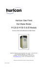
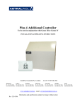
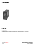
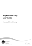
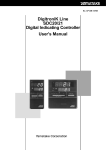
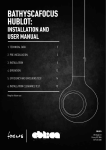
INSTALLATION AND OPERATING INSTRUCTIONS I INSTALLATION AND OPERATING INSTRUCTIONS HM Series Hydronic Boilers INSTALLATION AND OPERATING INSTRUCTIONS Melbourne: 03 9554 2275 Sydney: 02 9853 2100 Brisbane: 07 3308 5400 4/10/2010 Gold Coast: 07 5552 2600 Townsville: 07 4750 3100 Adelaide: 08 8152 7600 Perth: 08 9350 2600 sales@hurlconheating.com.au www.hurlconheating.com.au INDEX 1.0 INTRODUCTION ....................................................................................................................3 1.1 2.0 HM MODELS AVAILABLE ..................................................................................................4 2.1 3.0 4.0 5.0 NOTICE TO INSTALLERS ........................................................................................3 STANDARD EQUIPMENT – HM MODELS ...........................................................4 INSTALLATION ....................................................................................................................5 3.1 SAFETY RULES .........................................................................................................5 3.2 BOILER DIMENSIONS ..............................................................................................6 3.3 INDOOR INSTALLATION .........................................................................................6 3.4 VENTILATION – Air supply to the boiler .................................................................7 3.5 CLEARANCES ............................................................................................................8 3.6 ELECTRICAL CONNECTION ..................................................................................8 3.7 GAS CONNECTION...................................................................................................9 3.8 PUMP SELECTION:...................................................................................................9 COMMISSIONING............................................................................................................... 10 4.1 STARTING BOILER ................................................................................................ 10 4.2 TESTING BURNER PRESSURE.......................................................................... 10 4.3 CHECKING MINIMUM GAS PRESSURE ........................................................... 11 4.4 ADJUSTING MINIMUM GAS PRESSURE.......................................................... 11 4.5 FLOW SWITCH ........................................................................................................ 12 OPERATING INSTRUCTIONS ......................................................................................... 12 5.1 FROST PROTECTION ........................................................................................... 12 5.2 ENERGY SAVING TIPS ......................................................................................... 12 5.3 CONTROL SYSTEMS ............................................................................................ 13 ………………………………………………………………………………………………. 14 5.4 MAINTENANCE ....................................................................................................... 14 6.0 GAS CONVERSION ........................................................................................................... 15 6.1 BURNER CONVERSION ....................................................................................... 15 6.2 GAS PIPE SIZING TABLES .................................................................................. 16 7.0 TROUBLESHOOTING ....................................................................................................... 16 8.0 ………………………………………………………………………………………………. 17 HM SERIES WIRING DIAGRAM ...................................................................................... 18 9.0 8.1 MODEL 200 – 400 ................................................................................................... 18 8.2 MODEL 500 .............................................................................................................. 18 ONE YEAR LIMITED WARRANTY………………………………………………………………………….19 Inst195 HM Series Hydronic Boiler V10_10 2 1.0 INTRODUCTION Congratulations on your purchase of a Hurlcon Hydronic Boiler. Correct installation and service of your new heating system and correct chemical maintenance of the water will ensure years of service. The HM Series Boiler is a compact lightweight and efficient gas fired hydronic boiler. It is equipped with features that take advantage of new technology developed exclusively by Hurlcon. The Hurlcon is a floor mounted atmospheric boiler with a built in balanced flue for outdoor installation. The power output is controlled by an integrated electronic controller to maintain the set point water temperature over a wide load range. In addition, the Hurlcon Hydronic Boiler is equipped with electronic ignition. The electronic display tells at a glance the operational status of the boiler. Note: The appliance is not intended for use by young children or infirm person without supervision. Please ensure that young children are supervised to ensure that they do not play with the appliance. 1.1 NOTICE TO INSTALLERS This is a Floor Mounted - External - Hydronic Central Heating Boiler For use with Natural Gas or LP Gas as per the attached data label. Australian Gas Association Tested AGA Approval No. 6423 The information below is given to assist the installer with the installation of this range of HYDRONIC HM 200 - 500 Boilers. Please read it carefully in order to make the installation as easy as possible and to ensure the system works well and conforms to the necessary government regulations. PLEASE READ THESE INSTRUCTIONS BEFORE STARTING THE INSTALLATION. It is important that this boiler is installed and serviced as detailed in these instructions by an AUTHORISED person. This boiler is to be installed and serviced to the requirements of the Local Building, Gas, Water and Electricity Authorities. These instructions are to be held by the owner / user after installation. This boiler must not be used for a SPA or POOL Boiler This appliance must be installed in accordance with the installation instructions, local gas fitting regulations, the AGA Installation Code AG 601 and any other relevant statutory authorities. Refer to data plate for details of gas type, gas consumption and burner pressure. Inst195 HM Series Hydronic Boiler V10_10 3 2.0 HM MODELS AVAILABLE Model Input MJ (NG) Output kW 250 240 55 300 288 66 400 350 80 2.1 STANDARD EQUIPMENT – HM MODELS Electronic control including. PID control with auto tune. Set point shift via building automation system Displays set and flow temperature. Electronic ignition Safety devices Built in flow switch Built in run on timer for pump Manual reset high limit Reliable in high wind areas Built to last All copper double row heat exchanger Bronze headers with brass sensor pockets Fully powder coated steel cabinet Powder coated flue terminal Efficiency Hot surface intermittent pilot Highly efficient stainless steel burners Double row - counter flow heat exchanger Out door compensation ready, just add outdoor sensor Electronic gas modulation turn down 3 : 1 Ease of installation Fully plumbed ready to go All electrical pre wired including three pin power supply. Flow switch, run-on timer installed and wired Weather proof balanced flue external installation Terminal box for pump, outdoor compensation and room thermostat. Inst195 HM Series Hydronic Boiler V10_10 4 3.0 INSTALLATION THIS APPLIANCE MUST BE INSTALLED BY AN AUTHORISED PERSON. Refer to boiler data plate for specifications of gas type, gas consumption, burner pressure and water pressure. This appliance must be installed in accordance with local regulations and A.G.A. Installation Code AG 601. The boiler should always be installed downstream of the pump. The water connections are located on the left hand side of the boiler. Right hand connection models are available by special order. The inlet and outlet are clearly marked. Water connections are 1 ½” BSP FI. The Hurlcon Boiler is fitted with a built in flow switch and will not start unless full of water and the pump is operating. The Hurlcon Boiler incorporates a balanced flue terminal and is suitable for outdoor installation. An internal model is available on request. WARNING: An approved pressure relief valve must be fitted to this boiler before operation. 3.1 SAFETY RULES For your safety – read before lighting This appliance is equipped with an ignition device, which automatically lights the pilot. Do not try to light the pilot by hand. BEFORE OPERATING smell all around the appliance area for gas. Be sure to smell next to the floor because some gas is heavier than air and will settle on the floor. Safety What to do if you smell gas Do not try to light any gas appliance. Do not touch any electrical switch. Turn off the gas supply at the gas meter. Immediately call your gas supplier or licensed gas fitter. NOTE. Some gases are heavier than air and it may be necessary to smell for leaks at floor level. House keeping Do not store or use flammable liquid or chemicals near this appliance. Do not use aerosols in the vicinity of this gas appliance. Keep this appliance free of debris. WARNING: Should overheating occur or the gas supply fail to shut off, turn off the manual gas control valve to the appliance. Do not use this boiler if any part has been under water. Inst195 HM Series Hydronic Boiler V10_10 5 3.2 BOILER DIMENSIONS 3.3 INDOOR INSTALLATION If the HM Boiler is to be installed indoors, an indoor draught hood kit must be purchased from Hurlcon and installed on the HM Boiler to convert it to an indoor model. Product code numbers for draught hoods are: Boiler model HM 200 HM 250 HM 300 HM 400 HM 500 Indoor top model DH 20 DH 25 DH 30 DH 40 DH 50 Flue size 175 mm 175 mm 200 mm 250 mm 300 mm Part number 10966 10964 10967 10965 10968 A flue no smaller than the draught diverter diameter must be installed and terminated with an approved gas flue cowl (not a Chinaman’s hat) 600mm above any roofline that is within 1.5 metres horizontally from the flue. Inst195 HM Series Hydronic Boiler V10_10 6 3.4 VENTILATION – AIR SUPPLY TO THE BOILER When installing the boiler indoors, it is imperative that an adequate supply of fresh air is provided for combustion. Failure to provide adequate ventilation voids all warranties and may be a danger to persons or property. Please refer to AGA 601 for full details. Two permanent openings shall be provided directly to outside. The openings shall be located to ensure the distance between the top of the upper opening and the ceiling of the room or enclosure, and the distance between the bottom of the lower opening and the floor of the room or enclosure does not exceed 5% of the height of the room or enclosure. The minimum vertical dimension of any free ventilation opening shall be 6 mm. The minimum free ventilation area provided by each opening shall be: MODELS HM 2 AREA mm 200 65,000 250 80,000 300 100,000 400 130,000 500 160,000 The following diagram is provided as a guide only. All flueing and installation work must be carried out by an authorized person. Flueing must conform to local regulations and to A.G.A. installation code AG 601. Care must be taken to provide the correct ventilation and correct flueing materials in close proximity to combustible surfaces. 1500 600 Approved gas termination cowl Bolted sleeve to connect flue Draft diverter purchased from Hurlcon Upper grille for fresh air ventilation Lower grille for fresh air ventilation A Hurlcon indoor draught diverter must be fitted to unit in accordance with Hurlcon’s Instructions and Installation Codes before the boiler can be enclosed. Do not install spa blowers in the same room as a gas boiler. This is potentially dangerous to spa users. Do not store chemicals or fuel in the same room as the gas boiler. This may cause fire or explosion. When installing in a garage the HM Boiler must be installed 450 mm above floor level. Inst195 HM Series Hydronic Boiler V10_10 7 3.5 CLEARANCES The boiler must be installed at least 500 mm from any combustible surface. Clearances must comply with AG 601. Clearances from non combustible surfaces are: Front Both sides Rear Above Combustible Surfaces 500mm 500mm 500mm 1500mm 500mm Minimum Recommended service clearances 500mm on both sides and 1000 in front for component removal, connections and servicing. Boiler must be installed on a fireproof base. 3.6 ELECTRICAL CONNECTION The boiler is supplied with a standard 10 amp 3 pin plug for connection to a 240V 10 amp GPO. The boiler incorporates a 240/24 VAC transformer which supplies power to the control circuit only and must not be used for any additional equipment. All equipment connected to mains power should be protected by an RCD circuit breaker. The boiler has a 240 volt power supply for the pump electrical connection which incorporates the pump run on timer. A terminal strip is provided for a 24 volt room thermostat and the addition of an outdoor compensation sensor. If the supply cord is damaged, it must be replaced by the manufacturer or its service agent or a similarly qualified person in order to avoid a hazard. Electrical connections T1 T2 ROOM T’STAT O’DOOR SENSOR PUMP 5 amp max Connect circulator to these connections. 240 Volts- 5 Amps max. Use relays for higher capacity or 3 phase pumps. Field wiring of outdoor sensor by others Remove loop to connect room thermostat – 24 VOLT The thermostat cannot be powered from this circuit. A dry contact must be provided. Inst195 HM Series Hydronic Boiler V10_10 8 3.7 GAS CONNECTION The gas connection is on the left side of the boiler. A 20 mm (25mm for HM 500) flare nipple is provided for gas line connection. An approved manual shut off valve must be installed in the gas fitting line before the boiler so that the gas can be turned off and the boiler removed for servicing if required. The gas valves should be sized the same as the gas fitting line to prevent excessive pressure drop in the gas pipe. The gas fitting line should be installed by an authorised person and comply with local regulations and A.G.A. code AG 601. The gas line from the meter will usually be of a larger size than the gas inlet connection. Therefore a reduction to the boiler connection fitting will be necessary. The reduction should be as close to the boiler as possible. Before using the boiler, test all connections for gas leaks using soapy water. The boiler gas valve has a built in pressure regulator. A ⅛” pressure test point is provided on the burner manifold. On starting the boiler, a manometer must be used and burner pressure checked against the boiler data plate. The gas valve regulator may need adjustment to correct manifold pressure. Incorrect burner pressure may void warranty. 3.8 PUMP SELECTION: If a pump has not been supplied by your Dealer as part of this Boiler package, it will be necessary to size the Pump in accordance with the following flow rate and pressure drop chart. System pressure drop will need to be added to the corresponding boiler pressure drop. FLOW RATES & PRESSURE DROPS Boiler Model 250 300 400 Flow l/s 1.33 1.59 2.13 Boiler pressure drop kPa 1.90 2.50 5.10 Flow l/s 0.89 1.06 1.42 Boiler pressure drop kPa 1.60 2.00 4.20 Flow l/s 0.66 0.80 1.06 Boiler pressure drop kPa 0.44 0.69 1.47 10 Deg C Rise 15 Deg C Rise 20 Deg C Rise Inst195 HM Series Hydronic Boiler V10_10 9 4.0 COMMISSIONING 4.1 STARTING THE BOILER 1. Purge gas line of any air and wait five minutes for gas to clear. 2. Plug three pin plug into a suitable power point and switch on. The READY indicator should light. Digital controller should now operate and indicate water temperature 3. Pump should start, the FLOW indicator should light. 4. Turn Burner Switch ON. 5. After a few seconds, the burner should ignite. Ignition will be confirmed by the BURNER indicator. 6. If the burner fails to light, check FLOW indicator is on. Turn burner switch off then on to reset ignition system. 4.2 TESTING BURNER PRESSURE 1. Set up manometer 2. Turn boiler “OFF”. 3. Remove screw from ⅛” brass test point located on outlet side of gas valve/burner manifold 4. Connect manometer tube to test point 5. Turn boiler “ON” and wait for main burner to ignite and gas modulation to go to fully open. 6. Once main burner has ignited, the manometer must indicate the nominal burner pressure listed below. 7. To adjust gas valve regulator, remove regulator adjustment cap and, using a screwdriver, turn plastic bush clockwise to increase, anti-clockwise to decrease burner pressure. Maximum inlet gas pressure is: Natural Gas 3.5 kPa Propane Gas 3.5 kPa ULPG 3.5 kPa Nominal burner pressure is: Natural Gas kPa Propane Gas kPa ULPG kPa Inst195 HM Series Hydronic Boiler V10_10 High Flame Low Flame High Flame HM 250 0.82 0.10 2.50 HM 300 0.82 0.10 2.50 HM 400 0.75 0.10 2.50 Low Flame 0.80 0.80 0.80 High Flame 2.00 2.00 2.00 Low Flame 0.80 0.80 0.80 10 4.3 CHECKING MINIMUM GAS PRESSURE 1. 2. 3. 4. 5. 6. 7. 8. Set up manometer Turn boiler “OFF”. Remove screw from ⅛” brass test point located on outlet side of gas valve/burner manifold Connect manometer tube to test point Turn boiler “ON” and wait for main burner to ignite. Press and hold EXIT button for 5 seconds. Hand indicator lights. Press and hold Decrease button to move gas ball valve to lowest setting. Read gas pressure. 4.4 ADJUSTING MINIMUM GAS PRESSURE Increasing minimum gas pressure 1. 2. 3. 4. 5. Press Increase button until correct pressure is reached. Release locking screw. Move actuator to lowest setting. Tighten locking screw. Return to automatic operation by pressing EXIT for 5 seconds. Decreasing minimum gas pressure 1. 2. 3. 4. 5. 6. Release locking screw. Move actuator toward the maximum setting. Tighten locking screw. Press and hold Decrease button to move gas valve to lowest setting. Repeat until correct minimum gas pressure is achieved. Return to automatic operation by pressing EXIT for 5 seconds. Inst195 HM Series Hydronic Boiler V10_10 11 4.5 FLOW SWITCH The Hurlcon Boiler has an inbuilt flow switch which allows the burner to operate only when the system is full of water and the circulating pump is operating. NOTE: The installed flow switch has no user adjustments. Air in the system may stop the boiler from lighting 5.0 OPERATING INSTRUCTIONS STOP! Read the safety rules above. Turn off electric power to appliance. This appliance is equipped with an ignition device which automatically lights the pilot. Do not try to light the pilot by hand. Wait five minutes to clear out any gas. If you then smell gas, STOP! Refer to instructions above. Turn on power to appliance. Turn Burner Switch ON. The boiler will ignite in around 10 seconds. If the appliance will not operate, turn burner switch OFF for 5 seconds, then ON again. If the appliance still does not ignite, call your service technician. TO TURN GAS OFF TO APPLIANCE Turn off all electrical power to the appliance. Turn off gas tap in gas line prior to boiler. 5.1 FROST PROTECTION If there is any possibility of the boiler being left cold during frost conditions, an approved anti-freeze should be added. 5.2 ENERGY SAVING TIPS Make sure the ingress of cold air under doors and through gaps around windows is kept to a minimum. All open fire chimneys evaporative air-conditioning ducts etc should be closed to stop the loss of warm air. During the summer or while on vacation, turn the boiler off. Set up a regular program of preventative maintenance for the boiler each new heating season. Check heat exchanger, controls, burner operation etc. If the heating system will not be used for a prolonged period, turn the boiler off at the main gas valve and electrical power supply. Inst195 HM Series Hydronic Boiler V10_10 12 5.3 CONTROL SYSTEMS DIGITAL CONTROLLER OPERATION Manual operation Flow Temp. Control system ready Set Point Temp Modulating valve closing Modulating valve opening Not used 6 6 Limit Comparator Increase value button Decrease value button PGM PGM Program set button EXIT Program exit button EXIT WRF 40 DESCRIPTION The sophisticated digital thermostat controller provides display of water flow temperature, set point temperature and operating status of the boiler. TEMPERATURE DISPLAY The RED display indicates the flow water temperature from the boiler. The GREEN display indicates the boiler water flow set temperature. The controller is set to Hurlcon factory default settings at the time of manufacture. These settings are suitable for a wide range of applications but may require fine tuning depending on individual project specifications and characteristics. A detailed Siemens RWF 40 product manual is available on request which details how all settings are made and the auto tune function is activated. Standard settings are as follows Radiator & Fan Coil System Set temp Dead zone High limit Automatic reset High Limit Manual Reset 80 ˚C ± 5 ˚C 85 ˚C 90 ˚C Inst195 HM Series Hydronic Boiler V10_10 13 OPERATION Sequence of events once the boiler has been correctly installed with the room thermostat and burner turned off. Event Turn on electrical power to the boiler Turn on burner switch. Turn on room thermostat Water flow reaches set temperature. Water flow temperature reaches set temperature plus 5 ˚C Water flow temperature falls to set temperature. Water flow temperature reaches 90 ˚C Burner switch turned off Room thermostat switches off Room thermostat switches on Water flow stopped by external control Water flow is reinstated Result Controller powers up and completes test procedure. Pump starts up. Flow indicator on. Ignition sequence begins; checks water flow, high limit and flow temperature against set temperature. Modulation valve adjusts gas rate. Ready indicator on Burner lights. Burner indicator on. Modulation valve has reduced gas flow to hold set temperature. All indicators on Burner turns off. Burner indicator off Modulating gas valves starts to open. Burner relights. Burner indicator on High limit switch opens, burner shuts down. Pump continues to run for preset time. Burner shuts down, pump continues to run. Ready indicator off. Burner shuts down; pump continues to run for preset time. Ready indicator off. Pump restarts, burner ignites. Flow switch de-activates, burner turns off and pump continues to run for preset time. Flow indicator off. Flow switch reactivates, burner re ignites. Flow indicator on. 5.4 MAINTENANCE It is recommended that the following items are professionally checked at least every six months and at the beginning of every heating season. 1. Examine the balanced flue or indoor draught diverter. Make sure there are no obstructions to the flow of air to, or flue products from, the appliance. 2. Visually check the main burner and pilot flames. If the flame appears yellow, the burner should be cleaned by a qualified service technician. 3. Keep the boiler area clear and free of combustibles and flammable liquids. Chlorine should not be stored in the vicinity of the boiler. Chlorine vapours, when drawn through a boiler, can rapidly cause corrosion of the heat exchanger. 4. Keep the boiler area free from garden refuse and debris. This will help prevent insects nesting in the unit and ensure extended life and reliability of your boiler. Inst195 HM Series Hydronic Boiler V10_10 14 6.0 GAS CONVERSION 6.1 BURNER CONVERSION 1. 2. 3. 4. 5. 6. 7. 8. 9. 10. 11. 12. 13. 14. 15. 16. 17. 18. Model 200 250 300 400 500 Turn off gas supply to unit. Turn off power supply to pump and boiler. Remove front access door Disconnect gas supply from gas valve. Remove the two Phillips head screws from the angle brackets at the end of the manifold tube securing burner assembly to combustion chamber. Disconnect wiring from gas valve Remove drive motor form gas valve. Slide complete burner tray out through the access opening. Remove the four s/s bolts securing the injector manifold to the burner tray. Remove burner injectors and replace with desired gas type injectors. Remove pilot burner and change pilot injector to desired gas type. Remove regulator screw cap from top of gas valve Turn plastic plug anti-clockwise until fully removed and withdraw spring. Insert spring for desired gas type and re-install plastic plug. Re-install burner assembly and reconnect gas supply. Check gas system for leaks. Commence lighting procedure as described above. Adjust burner pressure as described above. Natural Gas Injector Pilot size Size N18 3.30 mm silver N18 3.30 mm silver N18 3.30 mm silver N18 3.30 mm silver N18 3.30 mm silver Burner pressure 0.82 kPa 0.82 kPa 0.82 kPa 0.75 kPa 0.78 kPa Inst195 HM Series Hydronic Boiler V10_10 Propane Gas Injector Pilot size size N10 1.9 mm black N10 1.9 mm black N10 1.9 mm black N10 1.9 mm black N10 1.9 mm black Burner pressure 2.50 kPa 2.50 kPa 2.50 kPa 2.50 kPa 2.50 kPa ULPG Gas Injector Pilot size size N10 1.9 mm black N10 1.9 mm black N10 1.9 mm black N10 1.9 mm black N10 1.9 mm black Burner pressure 2.00 kPa 2.00 kPa 2.00 kPa 2.00 kPa 2.00 kPa 15 6.2 GAS PIPE SIZING TABLES Natural gas at 1.13 kPa gas meter pressure VICTORIA Maximum run of copper pipe with average number of fittings Model 20 mm 25 mm 32 mm HM 200 2m 8m 30 m HM 250 6m 18 m HM 300 4m 14 m HM 400 3m 8m HM 500 1 6m 40 mm 75 m 45 m 35 m 20 m 14 m 1.25 kPa gas meter pressure S.A., W.A., some areas N.S.W. Maximum run of copper pipe with average number of fittings Model 20 mm 25 mm 32 mm HM 200 6m 25 m 90 m HM 250 4m 18 m 60 m HM 300 3m 14 m 45 m HM 400 2m 8m 25 m HM 500 6m 18 m 40 mm 240 m 160 m 110 m 70 m 45 m 2.75 kPa gas meter pressure N.S.W. some areas, some new areas of Victoria. Maximum run of copper pipe with average number of fittings Model 15 mm 20 mm 25 mm HM 200 4m 40 m 160 m HM 250 3m 25 m 100 m HM 300 2m 20 m 85 m HM 400 12 m 50 m HM 500 8m 35 m 32 mm 320+ m 320+ m 280 m 160 m 100 m 50 mm 320 m 220 m 140 m 90 m 60 m 50 mm 320 m 320 m 320 m 300 m 200 m 7.0 TROUBLESHOOTING BOILER WILL NOT LIGHT Possible cause Remedy Automatic ignition system fails Pump not running Pump air locked Flow switch open Defective gas control Thermostat turned off Set temperature lower than water temperature Water too hot-fault condition displayed High Limit Thermostat open Insufficient water flow Check water flow light indicator. Check pump and flow switch Air bleed system & pump bearing By pass to test Shut off gas supply and call for service Turn on Increase set temperature Refer to fault indication table Reset Check for too many valves turned off BOILER MAKING KNOCKING NOISES Possible cause Remedy Boiler operating after pump has shut off Heat exchanger scaled Shut off gas supply and call for service Shut off gas supply and call for service Inst195 HM Series Hydronic Boiler V10_10 16 If the boiler cannot be made to perform correctly, please contact the Hurlcon Service Office closest to you. For VICTORIA: NEW SOUTH WALES: QUEENSLAND: SOUTH AUSTRALIA WEST AUSTRALIA Phone (03) 9765 9765 Phone (02) 9674 8544 Phone (07) 3393 3233 Phone (08) 8345 5755 Phone (08) 9258 9322 For all other areas, please contact our Victorian office. Siemens RWF40 controller program standard settings To access press and hold PRG for 10 seconds Process data. Parameter Display Setpoint 1 * Setpoint 2 (optional) * Digital Setpoint Shift (optional) * SP1 SP2 Dsp Outside Temperature (optional) tA Predefinition of external setpoint * SPE Actual Factory Settings Setting 80 0 0 Parameter Level. Parameter Limit value of limit comparator * Switching differential for limit comparator * Proportional band * Derivative time Integral action time Contact spacing * Actuator running time Switch-on threshold burner / stage II * Switch-off threshold stage II * Upper switch-off threshold * Response threshold Heating curve slope Parallel displacement * Display AL HySt Pb.1 dt rt db tt HyS1 HyS2 HyS3 q H P Analog input 1, 2 & 3 setpoint changeover / shift Limit comparator: controller type: setpoint 1 locking Unit address decimal place / unit, signal for out-ofrange Measurement range start analog input 1 * Measurement range end analog input 1 * Measurement range start analog input 2 * Measurement range end analog input 2 * Lower setpoint limit * Upper setpoint limit * Actual value correction, analog input 1 * Actual value correction, analog input 2 * Actual value correction, analog input 3 * Filter time constant for digital filter, analog input 1 0 0 20 30 120 2 60 -2 0 4 0 4 0 Configuration Level. To access press and hold PRG for 10 seconds for second time Parameter Factory Setting Display Factory Setting C111 C112 9030 0010 C113 SCL SCH SCL2 SCH2 SPL SPH OFF1 OFF2 OFF3 DF1 0100 0 100 0 0 50 85 0 0 0 1 For OUTDOOR TEMP control refer to wiring diagram. For NIGHT SETBACK connect D2 and Ground on RWF40 to time clock delaya fully featured PID controllefact Inst195 HM Series Hydronic Boiler V10_10 17 8.0 HM SERIES WIRING DIAGRAM 8.1 MODEL 200 – 400 3 LED BOARD PUMP RUN ON TIMER WH BL WH BURNER ON/OFF RESET OR BR 15 A2 RD GY WH Q64 M9 Q63 B9 FUSE 18 A N E TRANSFORMER XU6 B1 M6 A3 RD BL OR PL BR HI LIMIT GY Q14 XB6 Q13 G1+ Y1 U1 Q M1 SENSOR BL PL 3 PIN PLUG OR FLOW SWITCH WH Y2 I1 N D2 L1 D1 OR - ORANGE GY - GREY BR - BROWN WH - WHITE RD - RED PL - PURPLE BL - BLUE GND OR GAS VALVE WH WH A N E TE G+ CA G- CG X1- CB X1+ PL O/A SENSOR THERMOSTAT PUMP CONNECTION BL OR PL BR Y1 G Y2 RWF40 CONTROLLER MOD GAS VALVE 8.2 MODEL 500 3 LED BOARD PUMP RUN ON TIMER WH BL WH BURNER ON/OFF RESET OR BR 15 A2 PL RD GY WH Q64 M9 Q63 B9 FUSE A N E 18 TRANSFORMER XU6 B1 M6 A3 RD BL OR BR PL HI LIMIT GY Q14 XB6 Q13 G1+ Y1 U1 Q M1 Y2 I1 N D2 L1 D1 SENSOR BL PL 3 PIN PLUG OR WH FLOW SWITCH OR OR - ORANGE GY - GREY BR - BROWN WH - WHITE RD - RED PL - PURPLE BL - BLUE GND WH WH WH IGNITION MODULE O/A SENSOR G+ CA G- CG X1- CB X1+ 3 1 6 9 4 5 2 RWF40 CONTROLLER D+ TH BL G IGNITOR Inst195 HM Series Hydronic Boiler V10_10 TE BR ANE THERMOSTAT PUMP CONNECTION BL OR PL OR GAS VALVE Y1 Y2 MOD GAS VALVE 18 9.0 ONE YEAR LIMITED WARRANTY GENERAL CONDITIONS Hurlcon cover your boiler with a limited 1 year warranty against defective materials and workmanship from the date of purchase (plus 30 days to allow for installation). The heat exchanger, including headers are covered by a five year warranty (plus 30 days to allow for installation). Proof of purchase date must be provided in order to substantiate warranty claim. The warranty includes in field labour costs where the boiler is installed in a capital city metropolitan area. Labour charges apply to boilers installed outside of these areas. Any costs for transport of faulty or replacement parts, removal or reinstallation are the owner’s responsibility. Hurlcon assumes no liability for consequential damages of any kind. Like your motor vehicle, your new boiler requires periodic service and maintenance to keep it operating in top condition and at maximum efficiency. An annual service by one of our qualified service technicians is highly recommended. LIMITATIONS All warranties only apply if the boiler is installed and operated in complete compliance with the installation and operating instructions. The warranty shall not apply to any boilers or parts that have been subject to accident, negligence, alteration, abuse or misuse. ADDITIONAL WARRANTY EXCLUSIONS: This warranty does not cover failures or malfunctions resulting from: Failure to properly install, operate or maintain the boiler in accordance with our printed instructions provided. Abuse, alteration, accident, fire, flood and the like. Examples of misuse or neglect include, but are not limited to, physical damage from external force, not following installation instructions, leaving door off for extended periods of time, inappropriate application of the boiler, etc. Scaling, freezing, or other conditions causing an inadequate water circulation. Incorrect gas pressure or gas supply. Incorrect or excessive flow rate of water. Failing to correct bleed water system of air. Chemical contamination of combustion air or use of chemical additives to the water. No person is authorised to make any warranties on Hurlcon’s behalf. To place a service call, contact your nearest Hurlcon office. Inst195 HM Series Hydronic Boiler V10_10 19 INSTALLATION AND OPERATING INSTRUCTIONS I INSTALLATION AND OPERATING INSTRUCTIONS HURLCON HEATING Pty. Limited. A.B.N. 97 007 284 504 www.hurlconheating.com.au email: service@hurlconheating.com.au Information and specifications subject to change without notice. Victoria: Ph: (03) 9554 2275 Fax: (03) 9554 2272 New South Wales: Ph: (02) 9853 2100 Fax: (02) 98532170 Queensland: Ph: (07) 3308 5400 Fax: (07) 3308 5470 Inst195 HM Series Hydronic Boiler V10_10 South Australia: Ph: (08) 8152 7600 Fax: (08) 8152 7670 Western Australia: Ph: (08) 9350 2600 Fax: (08) 9350 2670 Gold Coast: Ph: (07) 5552 2600 Fax: (07) 5552 2670 Townsville: Ph: (07) 4750 3100 Fax: (07) 4750 3170 20