1
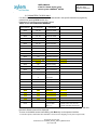
Technical Specification User’s Manual Logimac 280VM - PLC based control system Version : September2010 280VM USER’S MNUAL of the PLC-based duplex pump control system LOGIMAC® 280VM Page: 2 of 41 Date June 2012 Replacing: September 2010 . TABLE OF CONTENTS PAGE System parameters’ default settings------------------------------------------------------------------------------------------------------- 3 PLC read-only data registers readings ---------------------------------------------------------------------------------------------------- 4 1. INTRODUCTION----------------------------------------------------------------------------------------------------- 5 1.1 Approvals ---------------------------------------------------------------------------------------------------------------------------- 5 1.2 Part numbers------------------------------------------------------------------------------------------------------------------------ 5 2. HARDWARE DESCRIPTION ------------------------------------------------------------------------------------ 6 2.1 PLC configuration ----------------------------------------------------------------------------------------------------------------- 6 2.2 Operator interface ----------------------------------------------------------------------------------------------------------------- 7 2.3 Alarm annunciator ----------------------------------------------------------------------------------------------------------------- 8 3.PLC INPUT & OUTPUT CONNECTIONS -------------------------------------------------------------------- 10 4. PLC PROGRAM DESCRIPTION ----------------------------------------------------------------------------- 12 4.1 Initial parameter writing ---------------------------------------------------------------------------------------------------------12 4.2 Analog input/output reading & scaling.--------------------------------------------------------------------------------------13 4.3 Starting pump choice. ----------------------------------------------------------------------------------------------------------16 4.4 Contactor operation. ------------------------------------------------------------------------------------------------------------17 4.5 Alarms: memorizing, indication, acknowledge, reset--------------------------------------------------------------------18 4.6 Flushing once a day sequence -----------------------------------------------------------------------------------------------21 4.7 Pump capacity calculation------------------------------------------------------------------------------------------------------21 4.8 Pumped volume calculation ---------------------------------------------------------------------------------------------------23 4.9 VFD control operation -----------------------------------------------------------------------------------------------------------24 5. OPERATOR INTERFACE PROGRAM DESCRIPTION. --------------------------------------------------------27 5.1 Parameters to read only --------------------------------------------------------------------------------------------------------28 5.2 Parameters to read & write-----------------------------------------------------------------------------------------------------29 5.3 Alarm scanning--------------------------------------------------------------------------------------------------------------------34 5.4 System coldstart. -----------------------------------------------------------------------------------------------------------------35 5.5 Alarm register----------------------------------------------------------------------------------------------------------------------36 5.6 Display of the alarm register ---------------------------------------------------------------------------------------------------36 6. APPENDICES. -------------------------------------------------------------------------------------------------------------------- 37 © Copyright ITT Flygt 2004 FCDN-#95174-V4-LOGIMAC_280VM__USER`S_MANUAL.DOC P/N 13-52 20 36 USER’S MNUAL of the PLC-based duplex pump control system LOGIMAC® 280VM Page: 3 of 41 Date June 2012 Replacing: September 2010 . SYSTEM PARAMETERS’ DEFAULT SETTINGS FUNCTIO N KEY PLC REGISTER PARAMETER Write F3 - WritePREV-F3 102 New password 9 WRITE 24 # of pumps inPARAllel (in simultaneous operation) 2 526 Language F - French E - English INITIAL VALUE NOTES E - English 2- parallel operation 1-one pump only 24H-Flush disable Flush hour 24H WRITE 2 Start 1 delay 10 s WRITE 5 Start 2 delay WRITE 8 Blocking delay P1 15 s WRITE 11 Blocking delay P2 15 s WRITE 20 Alarm delay 5s WRITE 132 M1/M2 closing delay 10s WRITE 590/592 WRITE 70/72 WRITE 74 Start 1 level 100 cm WRITE 75 Start 2 level 120 cm WRITE 76 Stop 1 level 50 cm WRITE 77 Stop 2 level 50 cm WRITE 107 106 High level alarm Low level alarm 200 cm 0 cm WRITE 96 P1 max. current 50 A WRITE 98 P1 max. current 50 A WRITE 111 601 P1 high current alarm Delay 35 A 30s WRITE 112 604 P2 high current alarm Delay 35 A 30s WRITE 100 607 P1 low current alarm Delay 0A 30s WRITE 101 610 P2 low current alarm Delay 0A 30s WRITE ON/OFF - ALTERNATE Mode Choice ON `WRITE 94 M-zone Inferior Level 80cm `WRITE 95 M-zone superior Level 90cm L280CAP only WRITE 1060 M-zone AREA 0 m^2 Required for inflow calculation WRITE 113/2033 1P Cnom/Cref 0 l/s WRITE 115/2035 2p Cnom/Cref 0 l/s Cnom- required for inflow calculation WRITE 114 Capacity histeresis 0 l/s L280CAP only 30/36/60/09 Hz L280VFD only WRITE 1503/1505/1504/1506 10 s Flowmeter scaling Min/Max Level scaling Frequency:Min/Start/Max/D On Power up only 0-80l/s 0-320 cm ON OFF toggle P1lead/P2lead L280CAP only Cnom-required for inflow calculation © Copyright ITT Flygt 2004 FCDN-#95174-V4-LOGIMAC_280VM__USER`S_MANUAL.DOC P/N 13-52 20 36 USER’S MNUAL of the PLC-based duplex pump control system LOGIMAC® 280VM Page: 4 of 41 Date June 2012 Replacing: September 2010 . PLC READ-ONLY DATA REGISTER READING PARAMETER FUNCTION KEY of OPERATOR INTERFACE PLC REGISTER FUNCTION KEY PLC REGISTER READ 146, 143 Runtime P1 TOTAL READ 176, 173 Runtime P1 /DAY READ 155, 152 Runtime P2 TOTAL READ 185, 182 Runtime P2 /DAY READ 164, 161 Runtime P12 TOTAL READ 194, 191 Runtime P12 /DAY READ 217, 214 Overflow runtime READ 202 No. of starts P1 READ 205 No. of starts P2 READ 208 Hi level occurrences READ 220 Overflow occurrences READ 1503/1505/1504/ 1506 Freq:Min/Start/Max/D READ 1501/1502 SpeedP1/SpeedP2 READ 596 Flowmeter reading READ 136/223 READINGS 1 2 3 4 5 6 7 PARAMETER L280VFD only P1/P2 current READ 74 ,2 Start 1 Level & delay READ 75, 5 Start 2 Level & delay READ 76 Stop 1 Level 77 Stop 2 Level READ 70, 72 Level Range READ 1400 Pumped volume total READ 1402 Pumped volume/day READ 1645 Dynamic inflow READ 1024 Cycle inflow L280CAP only READ 1300 P1Capacity calcul. L280CAP only READ 1302 P2Capacity calcul. L280CAP only READ 1308 2P Capacity calcul. L280CAP only Read than ALM 270 Alarm register © Copyright ITT Flygt 2004 FCDN-#95174-V4-LOGIMAC_280VM__USER`S_MANUAL.DOC P/N 13-52 20 36 USER’S MNUAL of the PLC-based duplex pump control system LOGIMAC® 280VM Page: 5 of 41 Date June 2012 Replacing: September 2010 . INTRODUCTION The LOGIMAC® 280VM P/N 13-50 90 90 was designed for the control and supervision of a sewage pumping station with one or two pumps. The complete system consists of programmable logic controller LOGIMAC® 280VM-PLC as per the configuration specified in the following chapter, the operator interface LOGIMAC® 280VM-OP and the alarm annunciator LOGIMAC® 280-AP. LOGIMAC® 280-PLC takes an analog level signal 4-20 mA from any of the level sensor with that kind of output. The controller can be used in one of the three programmed mode which is set before shipping: L280 as previous Logimac 280CIM L280CAP with pumps’ capacities calculation L280VFD with VFD control following the level changes Dynamic inflow & pumped volume can be calculated in any of modes. 1.1 Approvals Sensor: CSA certified for operation in Class I, Division 2, Groups C and D hazardous environments. (Note: For this approval to be valid special installation conditions apply). 1.2 Part numbers LOGIMAC® 280VM-PLC (P/N 13-50 90 91 Analog I/O expansion unit (P/N 13-40 02 30) LOGIMAC® 280-AP (P/N 13-50 90 19) LOGIMAC® 280VM-OP (P/N 13-50 90 92) © Copyright 1995 ITT Flygt ® The LOGIMAC is registered mark of ITT Flygt. All rights reserved. No part of this manual may be reproduced or copied without the written permission of ITT Flygt. © Copyright ITT Flygt 2004 FCDN-#95174-V4-LOGIMAC_280VM__USER`S_MANUAL.DOC P/N 13-52 20 36 USER’S MNUAL of the PLC-based duplex pump control system LOGIMAC® 280VM Page: 6 of 41 Date June 2012 Replacing: September 2010 . 2. HARDWARE DESCRIPTION 2.1 LOGIMAC® 280-PLC CONFIGURATION The programmable logic controller (PLC) is composed of the modules specified in the table 2.1 below depending on power supply module . 2.1 CONFIGURATION of LOGIMAC® 280VM-PLC ITEM # DESCRIPTION CPU & Memory TECHNICAL DATA Flash user memory program memory: 9 Kwords storage memory: 2 Kwords operation speed: 1.0 ms/ 1Kword of logic user program: L280VM P/N 16 - inputs 24V DC; current consumption: 7.3mA max./point 11 relays+1 DC -outputs Operating voltage: 5-30 V DC 13-50 90 91 5-250 V AC max. load: 2A resistive/ 0.6A inductive Supply 120V AC ( 102 -132V), 60 Hz (47- 63 Hz) DC output power supply: 24V + -10%, 200 mA max. current P/N 13-40 02 30 Dimensions (90H x 150W x76D) mm service temperature 0..+55°C stocking temperature -40..+85°C Port Two serial ports:1: RS 232, 2: RS 485 Removable terminal strip included Analogue Expansion unit Inputs: current 4-20mA 4-inputs/2-outputs outputs: current 4-20mA Supply : 120V AC ( 102 -132V), 60 Hz (47- 63 Hz) Dimensions: 90H x 95W x76D) mm © Copyright ITT Flygt 2004 FCDN-#95174-V4-LOGIMAC_280VM__USER`S_MANUAL.DOC P/N 13-52 20 36 USER’S MNUAL of the PLC-based duplex pump control system LOGIMAC® 280VM Page: 7 of 41 Date June 2012 Replacing: September 2010 . 2.2 OPERATOR INTERFACE LOGIMAC® 280-OP The operator interface LOGIMAC® 280-OP is is a fully programmable man-machine interface. One part of a programming can be done using the software, specific for the unit, and another one should be programmed in the PLC program software for PLC ladder programming. The operator interface is equipped of: • • • • • • • • 8-01 SYSTEM OK LEVEL: 120 cm Read Write 6 programmable function-key Alpha-numeric key-pad LCD screen 160x32 pixels (89.6x17.9mm display) for small graphic/80 total characters on 4 lines PLC communication port RS 232 RS422/RS485 serial programming port cable: operator interface-PLC (DB9F- RG45) The supply voltage 24VDC Power consumption: Normal 0.1A @ 24VDC, Max 0.3A 14:50 Function-keys description D&T Function-keys FIG.1 Operator interface unit LOGIMAC 280VM-OP The operator interface was fully programmed for this application (see description of this programming in chapter 5 of this manual). For further details, please refer to the manufacturer user manual supplied with unit. © Copyright ITT Flygt 2004 FCDN-#95174-V4-LOGIMAC_280VM__USER`S_MANUAL.DOC P/N 13-52 20 36 USER’S MNUAL of the PLC-based duplex pump control system LOGIMAC® 280VM Page: 8 of 41 Date June 2012 Replacing: September 2010 . 2.3 ALARM ANNUNCIATOR LOGIMAC® 280-AP 2.3.1 TECHNICAL DATA : Supply voltage: 24V DC Current consuming: 80 mA. 2.3.2 COMPONENTS and THEIR FUNCTIONS: The annunciator is composed of four (4 ) integrates parts: • Printed circuit board (P/N 13-50 90 59) • Face plate with descriptions (P/N 13-51 15 34) • Board connector with terminal (P/N13-42 00 03) • Flat cable (P/N 13-41 00 15) The printed circuit board circuit contains: • • • • represent the circuit as per drawing 2603-A2 (see appendices 1). The 13 diodes LED ( D1..D13), 2 push buttons (SW1et SW2), 13 resistors (R1..R13) to limit the current and 26 auxiliary diodes of type 1N4004 (D14.. 39). Each parallel circuit (total 16 circuits) is connected to one pin (1-16) of the (P1) plug for the flat cable . The functions of circuit are : Indication: The positive (+) signal of 24V DC power supply connected to terminal 2 is common for all diodes LED. To turn on the diode LED, the negative (-) signal should be connected to another end of circuit. It can be done if the PLC output relay contact, connected to the specific LED circuit closes (All PLC outputs connected to annunciator should have the common terminal COM connected to negative (-) terminal of source). Lamp test: The negative (-) signal of 24V DC power supply connected to terminal 1 is used to test LED diodes. Pushing the push button SW1, connects 24V DC power supply to all LED diode circuits and turn all LED’s on. Acknowledge/Reset: By pressing the push button SW2, the positive (+) signal of 24V DC power supply will be connected to PLC input being connected to terminal 4 of the annunciator. This input signal is programmed in PLC as acknowledge signal ( first appearance) and as reset signal (second appearance). It is important to connect the common terminal COM of this PLC input to negative ( - ) terminal of source. © Copyright ITT Flygt 2004 FCDN-#95174-V4-LOGIMAC_280VM__USER`S_MANUAL.DOC P/N 13-52 20 36 USER’S MNUAL of the PLC-based duplex pump control system LOGIMAC® 280VM Page: 9 of 41 Date June 2012 Replacing: September 2010 . Faceplate is a two-side lamicoid plate with descriptions in English on one side, and in French on another. The descriptions are as per drawing C-51 15 34 (See appendices 1). Board connector with terminal is composed of 16 screw-terminals connected to a 16-pin male plug (P2) for flat cable. The flat cable is a 2-meters length flat cable with one female-plug on each end, which can be plug in: • the P1 plug (on printed circuit board) and • the P2 plug ( on board connector with terminals). © Copyright ITT Flygt 2004 FCDN-#95174-V4-LOGIMAC_280VM__USER`S_MANUAL.DOC P/N 13-52 20 36 USER’S MNUAL of the PLC-based duplex pump control system LOGIMAC® 280VM Page: 10 of 41 Date June 2012 Replacing: September 2010 . 3. LOGIMAC® 280-PLC INPUT & OUTPUT CONNECTION LOGIMAC® 280-PLC has 16 digital inputs, 11 digital relay-based outputs, 1 transistor digital output (high speed) d 4 analog 4-20 mA inputs & 2 analog outputs. For this application the inputs and outputs are assigned to the signals specified in the table 1, 2, 3 and 4 respectively. TABLE 1.: DIGITAL INPUT ASSIGNATION INPUT DESCRIPTION NOTES 1 ACKNOWLEDGE/ RESET signal provided by push button “ACKNOWLEDGE/ RESET on the alarm annunciator 2 P1 AUTO P1 mode selector in AUTO position 3 P2 AUTO P2 mode selector in AUTO position 4 GEN SET RUN GEN SET RUN NO contact. If closed , one pump only is allowed to run (no parallel operation of two pumps) 5 OL1( B1) contact indicating overcurrent of the P1 pump (breaker auxiliary contact) 6 R6 leakage. P1 interface relay contact from Mini CAS II unit indicating a water leakage in P1 pump 7 R5 high temp. P1 interface relay contact from Mini CAS II unit indicating a high temperature in P1 pump 8 OL2( B2) contact indicating overcurrent of the P2 pump (breaker auxiliary contact) 9 R8 leakage P2 interface relay contact from Mini CAS II unit indicating a water leakage in P2 pump 10 R7 high temp.P2 interface relay contact from Mini CAS II unit indicating a high temperature in P2 pump 11 FLH or ISRH high level contact indicating the high level reached (follows FLH float NO contact) 12 Overflow (optional) contact indicating the overflow level reached.(FLOV float NO contact) 13 FLL or ISRL low level contact indicating the low level reached (follows FLL float NC contact) 14 PFD voltage or phase failure detection (PFD) 15 M1 contactor closed auxiliary contact of the M1 contactor to indicate the contactor status 16 M2 contactor closed auxiliary contact of the M2 contactor to indicate the contactor status For wiring details see drawing E-97786: LOGIMAC 280VM I/O connection © Copyright ITT Flygt 2004 FCDN-#95174-V4-LOGIMAC_280VM__USER`S_MANUAL.DOC P/N 13-52 20 36 USER’S MNUAL of the PLC-based duplex pump control system LOGIMAC® 280VM Page: 11 of 41 Date June 2012 Replacing: September 2010 . TABLE 2.: DIGITAL OUTPUT ASSIGNATION OUTPUT DESCRIPTION NOTES 1 spare 24V DC output 2 M1 closing signal order to close the M1 contactor (interface relay R1) 3 M2 closing signal order to close the M2 contactor (interface relay R2) 4 COMMON alarm Common alarm signal for remote transmission (interface relay R14) 5 High level alarm HIGH LEVEL alarm signal (120V AC circuit) 6 Low level alarm LOW LEVEL alarm signal to the alarm annunciator 7 P1 OVERLOAD alarm /M1 closing fault P1 OVERLOAD alarm signal to the alarm annunciator (this output is also activated if M1 contactor does not close its contact during ten (10) seconds following the order to close - R1 relay contact closing) 8 P2 OVERLOAD alarm /M2 closing fault P2 OVERLOAD alarm signal to the alarm annunciator (this output is also activated if M2 contactor does not close its contact during ten (10) seconds following the order to close - R2 relay contact closing 9 P1 leakage alarm P1 LEAK. alarm signal to the alarm annunciator 10 P2 leakage alarm P2 LEAK. alarm signal to the alarm annunciator 11 P1 high temp. alarm P1TEMP alarm signal to the alarm annunciator 12 P2 high temp. alarm P2 TEMP alarm signal to the alarm annunciator For wiring details see drawing E-97786: LOGIMAC 280VM I/O connection TABLE 3 ANALOG INPUT ASSIGNATION INPUT DESCRIPTION Notes 1 Level signal Level signal from an ultrasonic sensor. Use the operator interface for scaling 2 P1 current signal P1 pump current signal from current transducer. Use the (optional) operator interface for scaling 3 P2 current signal P2 pump current signal from current transducer. Use the (optional) operator interface for scaling 4 Flowmeter Signal of flow from Flowmeter (4-20mA) For wiring details see drawing E-97786: LOGIMAC 280VM I/O connection TABLE 4 ANALOG OUTPUT ASSIGNATION OUTPUT DESCRIPTION Notes 1 P1 VFD signal 4-20 mA signal to control VFD (P1) following level changes 2 P2 VFD signal 4-20 mA signal to control VFD (P2) following level changes For wiring details see drawing E-97786: LOGIMAC 280VM I/O connection © Copyright ITT Flygt 2004 FCDN-#95174-V4-LOGIMAC_280VM__USER`S_MANUAL.DOC P/N 13-52 20 36 USER’S MNUAL of the PLC-based duplex pump control system LOGIMAC® 280VM Page: 12 of 41 Date June 2012 Replacing: September 2010 . 4. PLC PROGRAM DESCRIPTION 4.1 INITIAL PARAMETERS WRITING During the first scan or coldstart of the program the initial default parameters are automatically written to the assigned memory registers. TABLE 4 presents the list of the parameters and their default values. An operator can read or change (write) these parameters using operator interface function keys listed in the first column of the table (see 5.2 chapter for details). TABLE 4: SYSTEM PARAMETERS’ DEFAULT SETTINGS FUNCTIO N KEY PLC REGISTER PARAMETER Write F3 - WritePREV-F3 102 New password 9 WRITE 24 # of pumps inPARAllel (in simultaneous operation) 2 526 Language F - French E - English INITIAL VALUE NOTES E - English 2- parallel operation 1-one pump only 24H-Flush disable Flush hour 24H WRITE 2 Start 1 delay 10 s WRITE 5 Start 2 delay WRITE 8 Blocking delay P1 15 s WRITE 11 Blocking delay P2 15 s WRITE 20 Alarm delay 5s WRITE 132 M1/M2 closing delay 10s WRITE 590/592 WRITE 70/72 WRITE 74 Start 1 level 100 cm WRITE 75 Start 2 level 120 cm WRITE 76 Stop 1 level 50 cm WRITE 77 Stop 2 level 50 cm WRITE 107 106 High level alarm Low level alarm 200 cm 0 cm WRITE 96 P1 max. current 50 A WRITE 98 P1 max. current 50 A WRITE 111 601 P1 high current alarm Delay 35 A 30s WRITE 112 604 P2 high current alarm Delay 35 A 30s WRITE 100 607 P1 low current alarm Delay 0A 30s WRITE 101 610 P2 low current alarm Delay 0A 30s WRITE ON/OFF - ALTERNATE Mode Choice ON `WRITE 94 M-zone Inferior Level 80cm `WRITE 95 M-zone superior Level 90cm L280CAP only WRITE 1060 M-zone AREA 0 m^2 Required for inflow calculation WRITE 113/2033 1P Cnom/Cref 0 l/s Cnom-required for inflow calculation WRITE 115/2035 2p Cnom/Cref 0 l/s Cnom- required for inflow calculation WRITE 114 Capacity histeresis 0 l/s L280CAP only 30/36/60/09 Hz L280VFD only WRITE 1503/1505/1504/1506 10 s Flowmeter scaling Min/Max Level scaling Frequency:Min/Start/Max/D On Power up only 0-80l/s 0-320 cm ON OFF toggle P1lead/P2lead L280CAP only © Copyright ITT Flygt 2004 FCDN-#95174-V4-LOGIMAC_280VM__USER`S_MANUAL.DOC P/N 13-52 20 36 USER’S MNUAL of the PLC-based duplex pump control system LOGIMAC® 280VM Page: 13 of 41 Date June 2012 Replacing: September 2010 . 4.2 ANALOG INPUT/OUTPUT READING & SCALING All analog inputs are based on 12-bit analog-digital converter. During each scan of program 12 bits are converted in 16-bit analog data word %AI. Factory scaling for analog inputs of 4-20 mA and the corresponding level and the pump current scaling for the default ranges is provided on fig.2 and 3. 320 28000 280 24000 240 20000 200 16000 160 12000 120 8000 80 4000 40 20 19 18 17 16 15 14 13 12 11 10 9 8 7 6 5 4 3 2 0 1 0 water level in cm 32000 0 value in PLC LOGIMAC 280 PLC analog input (level sensor) sensor current in mA FIG. 2 ANALOG INPUT SCALING (LEVEL) The scaling will be automatically changed by PLC if an operator provides different values of ranges using the operator interface. © Copyright ITT Flygt 2004 FCDN-#95174-V4-LOGIMAC_280VM__USER`S_MANUAL.DOC P/N 13-52 20 36 USER’S MNUAL of the PLC-based duplex pump control system LOGIMAC® 280VM Page: 14 of 41 Date June 2012 Replacing: September 2010 . LOGIMAC 280 PLC analog input (current sensor) 50 32000 45 28000 40 P U M 35 P 24000 V A 20000 L U E 16000 C 30 U R R 25 E N T 20 I N 15 I N 12000 P L C A 8000 10 4000 0 5 0 1 2 3 4 5 6 7 8 9 10 11 12 13 14 15 16 17 18 19 20 0 sensor current in mA FIG.3 ANALOG INPUT SCALING (CURRENT) If the inputs of pumps’ currents are not used, no changes are required in default values of ranges. The PLC will treat these inputs as a zero signal. © Copyright ITT Flygt 2004 FCDN-#95174-V4-LOGIMAC_280VM__USER`S_MANUAL.DOC P/N 13-52 20 36 USER’S MNUAL of the PLC-based duplex pump control system LOGIMAC® 280VM Page: 15 of 41 Date June 2012 Replacing: September 2010 . Logimac 280VM output scalling 20 F Maximum (default 60Hz) Output current in mA 16 12 8 F MINimum (default 30Hz) 4 0 0 4000 8000 12000 16000 20000 Value in PLC Applicable for controls using the Logimac280VFD only © Copyright ITT Flygt 2004 FCDN-#95174-V4-LOGIMAC_280VM__USER`S_MANUAL.DOC P/N 13-52 20 36 24000 28000 32000 USER’S MNUAL of the PLC-based duplex pump control system LOGIMAC® 280VM Page: 16 of 41 Date June 2012 Replacing: September 2010 . 4.3 STARTING PUMP CHOICE The control system allows the operation of either one or two pumps in parallel but prevents simultaneous start of two pumps. In automatic mode a choice of the pump to start is done by the PLC program following the conditions specified below: P1 PUMP is chosen to start as a duty pump if : • • • • The start conditions are reached (water level is higher than START 1 or high level float is active) and P1 pump is operational (no faults) and the alternate mode is not chosen or P2 pump is faulty, or the alternate mode is chosen but P2 pump operation had been memorized or P1 operation had not been memorizing P2 PUMP is chosen to start as a duty pump if : • • • • The start conditions are reached (water level is higher than START 1 or high level float is active) and P2 pump is operational (no faults), and the P1 pump is faulty, or the alternate mode is chosen and the P1 cycle of operation had been memorized, P1 PUMP is chosen to start as a standby pump if : • • • The parallel operation conditions are reached (water level is higher than START 2 level or high level float is active) and P1 pump is operational (no faults), and M2 contactor is closed P2 PUMP is chosen to start as a standby pump if : • • • The parallel operation conditions are reached (water level is higher than START 2 level or high level float is active) and P2 pump is operational (no faults) , and M1 contactor is closed To start the pump, either the start conditions or parallel conditions should be kept during at least 10second period calling START DELAY. The default value of 10 seconds can be changed by operator (see TIME DELAY CHANGE in chapter 5.2) If one of pumps is stopped (for whatever reason) the BLOCKING DELAY will be activated. Neither the pump P1 or P2 can start during this period (two pumps will be prevented to start). If two pumps are running and one of them stops this delay will not have effect on running pump. The default value of the BLOCKING DELAY are 15 s and can be adjusted by operator using operator interface for each pump separately (see TIME DELAY CHANGE in chapter 5.2). © Copyright ITT Flygt 2004 FCDN-#95174-V4-LOGIMAC_280VM__USER`S_MANUAL.DOC P/N 13-52 20 36 USER’S MNUAL of the PLC-based duplex pump control system LOGIMAC® 280VM Page: 17 of 41 Date June 2012 Replacing: September 2010 . 4.4 CONTACTOR OPERATION In automatic mode the M1 contactor (or the M2 contactor) will close following the closing signal from R1 (or R2) interface relay after START DELAY as specified in previous chapter. Reception of the contactor closing confirmation by PLC will be indicated by turning on the respective diode LED labeled RUN P1 or RUN P2 on the alarm annunciator (see appendices 1 for annunciator details). NOTE: Closing fault: If PLC does not receive a confirmation of the contactor closing (see M1 or M2 contact as PLC inputs) during the 10-second period following the closing order (R1 or R2 relay contact closing), the closing order will be removed and the alarm will be signaled. In automatic mode, if stop conditions are reached, the running pump contactor will open. If two pumps are running, M1 contactor opens first (on STOP 1) and M2 contactor follows (on STOP2). Each contactor can be open or closed manually, using a mode selector MAN-OFF-AUTO (MAN-OFF positions). Either during manual or automatic operation the contactor opens automatically on fault conditions of the respective pump. © Copyright ITT Flygt 2004 FCDN-#95174-V4-LOGIMAC_280VM__USER`S_MANUAL.DOC P/N 13-52 20 36 USER’S MNUAL of the PLC-based duplex pump control system LOGIMAC® 280VM Page: 18 of 41 Date June 2012 Replacing: September 2010 . 4.5 ALARMS : Memorizing, indication, acknowledge, reset. 4.5.1 P1 or P2 pump OVERLOAD / M1 or M2 contactor CLOSING FAULT On the overload fault, the respective pump breaker opens. Auxiliary contacts of breakers are used as the overload signal for PLC inputs (OL1or B1, OL2 or B2). If one of contacts is closed (OL1 or OL2), the corresponding contactor closing signal will be removed ( see R1 or R2 relay) and the OVERLOAD alarm will be memorized in PLC memory and be indicated by the flashing LED diode (OVERLOAD P1 or OVERLOAD P2) on the alarm annunciator. The LED diodes OVERLOAD P1 or OVERLOAD P2 turn on also in the case of Closing fault of the M1 or M2 contactor (see NOTE in previous chapter). A distinction between OVERLOAD and CONTACTOR CLOSING FAULT can be seen on the operator interface message. This alarm will be held, even if the fault conditions disappear. The contactor of the pump in fault will open automatically and cannot be closed without an operator intervention. Reset the circuit after the fault correction: push the RESET push-button once for acknowledge (LED stops flashing), and twice for reset. 4.5.2. ALARM: WATER LEAKAGE OF P1/ P2 PUMP The faults detection will be done by the sensors attached to Mini CAS II units of ITT Flygt. The interface relay of this unit (R6 or R8) operates if water is detected in the corresponding pump. The contact of this relay is connected to PLC input to provide the information. If one of these contacts is closed, the corresponding contactor closing signal will be removed (see R1 or R2 relay) and the alarm LEAKAGE will be memorized in PLC memory and be indicated by the flashing LED diode ( LEAK. P1 or LEAK. P2) on the alarm annunciator. This alarm will be held, even if the fault conditions disappear. The contactor of the pump in fault will open automatically and cannot be closed without an operator intervention. Reset the circuit after the fault correction: push the RESET push-button once for acknowledge (LED stops flashing), and twice for reset. 4.5.3. ALARM: HIGH TEMPERATURE OF P1/ P2 PUMP The faults detection will be done by the sensors attached to Mini CAS II units of Flygt. The interface relay of this unit (R5 or R7) operates if a temperature of pump goes higher than sensor adjustment in the corresponding pump. The contact of this relay is connected to PLC input to supply the information. If one of these contacts is closed, the corresponding contactor closing signal will be removed ( see R1 or R2 relay) and the alarm HIGH TEMPERATURE will be memorized in PLC memory and will be indicated by flashing LED diode (TEMP P1 or TEMP P2) on the alarm annunciator. This alarm will be held, even if the fault conditions disappear. The contactor of the pump in fault will open automatically and cannot be closed without an operator intervention. Reset the circuit after the fault correction: push the RESET push-button once for acknowledge (LED stops flashing), and twice for reset. © Copyright ITT Flygt 2004 FCDN-#95174-V4-LOGIMAC_280VM__USER`S_MANUAL.DOC P/N 13-52 20 36 USER’S MNUAL of the PLC-based duplex pump control system LOGIMAC® 280VM Page: 19 of 41 Date June 2012 Replacing: September 2010 . 4.5.4. ALARM: HIGH WATER LEVEL The fault detection is done by FLH float or by analog level sensor (version 1.4 or later). When float is tilted its normally open contact (NO) (or ISRH interface relay ) closes. That contact is connected to the PLC input 11. If this contact is closed, a HIGH LEVEL alarm will be indicated by the LED diode (HIGH LEVEL) on the alarm annunciator. This alarm will disappear from annunciator if fault conditions disappear. The High level alarm is also activated when the level reaches the High level value adjusted using operator interface. In both cases R14 relay will operate (its NO contact is available for a remote transmission of the ALARM signal). The common alarm will stay even if fault condition disappears. Reset the circuit after the fault correction: push the RESET push-button twice for reset The output 5 gives a High Level signal. This output is energized on High Level float tilted. This output can be used to connect the interposing relay (with 120V AC coil) if a dry contact is needed for remote High Level alarm indication. 4.5.5. ALARM: LOW LEVEL The faults detection is done by FLL float or by analog level sensor (version 1.4 or later). The normally closed contact of the float (or normally open contact (NO) of ISRL interface relay) is connected to the PLC input. If this contact is closed, a LOW water LEVEL alarm will be memorized in PLC memory and will be indicated by the flashing LED diode (LOW LEVEL) on the alarm annunciator. This alarm will be registered and indicated on the annunciator even if fault conditions disappear. The Low level alarm is also activated when the level reaches the Low level value adjusted using operator interface. In both cases R14 relay will operate (its NO contact is available for a remote transmission of the ALARM signal). The common alarm will stay even if fault condition disappears. Reset the circuit after the fault correction: push the RESET push-button twice for reset. The contactors of the pumps will open automatically but can be closed if fault conditions disappear. Reset the circuit after the fault correction: push the RESET push-button once for acknowledge (LED stops flashing), and twice for reset . 4.5.6. ALARM: POWER FAILURE The faults detection will be done by the power failure detector (PFD) connected to three phases of the power entrance. The PFD operates on phase or power failure. Its NC contact is open if three phases are present and voltage value is between adjusted limits. On fault this contact will close. If this contact is closed, the contactor closing signals will be removed (see R1 and R2 relays) and the alarm POWER FAILURE will be indicated by the LED diode (POWER FAILURE) on the alarm annunciator. This alarm will disappear if fault conditions disappear. On fault the contactors will open automatically but can be closed following start sequence if the utility power is back to normal. © Copyright ITT Flygt 2004 FCDN-#95174-V4-LOGIMAC_280VM__USER`S_MANUAL.DOC P/N 13-52 20 36 USER’S MNUAL of the PLC-based duplex pump control system LOGIMAC® 280VM Page: 20 of 41 Date June 2012 Replacing: September 2010 . 4.5.7. ALARM: P1/P2 PUMP LOW CURRENT If the pump current analog inputs are used these alarms can be available. The limit values for these alarms can be provided by an operator using the operator interface (see chapter 5.2 for details). The default values are established as zero (0) Amps. An operator can change these values for the LOWEST POSSIBLE CURRENT established during pump’s running test. If the pump current value is lower than established lowest value for respective pump, LOW CURRENT OF P1 (or P2) PUMP alarm will be registered in PLC memory. The 30-seconde delay (by default) prevents the activation of the alarm during transient conditions. This alarm will be indicated on operator interface display (see chapter 5.3 “Alarm scanning” for details). This alarm will be held, even if the fault conditions disappear. The contactor of the pump in fault will open automatically and cannot be closed without an operator intervention. Reset the circuit after the fault correction: push the RESET push-button once for acknowledge, and twice for reset. 4.5.8. ALARM: P1/P2 PUMP HIGH CURRENT If pump current analog inputs are used these alarms can be available. The limit values for these alarms can be provided by an operator using the operator interface (see chapter 5.2 for details). The default values are established on 350 Amps. An operator can change these values for the HIGHEST POSSIBLE CURRENT established during pump’s running test. If the pump current value I1 (or I2) is higher than established highest value for respective pump, the HIGH CURRENT OF P1 (or P2) PUMP alarm will be registered in PLC memory. The 30-seconde delay (by default) prevents the activation of the alarm during transient conditions. This alarm will be indicated on the operator interface display (see chapter 5.3 Alarm scanning for details). This alarm will be held, even if fault conditions disappear. The contactor of the pump in fault will open automatically and cannot be closed without an operator intervention. Reset the circuit after the fault correction: push the RESET push-button once for acknowledge, and twice for reset. 4.5.9. COMMON ALARM All alarms described above will activate the COMMON ALARM OUTPUT with R14 interface relay. The contacts of this relay are available to remote control or indication. © Copyright ITT Flygt 2004 FCDN-#95174-V4-LOGIMAC_280VM__USER`S_MANUAL.DOC P/N 13-52 20 36 USER’S MNUAL of the PLC-based duplex pump control system LOGIMAC® 280VM Page: 21 of 41 Date June 2012 Replacing: September 2010 . 4.6 FLUSHING ONCE A DAY SEQUENCE The special sequence is programmed to do a flushing of a piping system once a day. It can be used either for a system designed for an operation of one pump only at the time (setting of # of pumps in PARAllel: 1) or for the system where two pumps are allowed in parallel operation (setting of # of pumps in PARAllel: 2). The hour of flushing can be adjusted on the operator interface (see first screen under function key F2 write). The default value is 24h, which made this function disable. Operator should set the hour of flushing (0 - 23h). If this hour is reached a START 1 level set value will be ignored. Two pumps will start if level START 2 is reached. As usual the start delay is applied between pump starts to prevent simultaneously start of two pumps. Two pumps will stop on STOP level. Once the flushing cycle finished the system return to the normal sequence. 4.7 PUMP CAPACITY CALCULATION (For L280CAP only) The PLC is programmed to calculate the pump capacity using so-called Jacuzzi Jaeger method. The method requires a MEASURE ZONE (a volume bounded by two sump levels: inferior level and superior level) to be defined. The MEASURE ZONE should be chosen between last STOP level and first START. In addition to these levels, the MEASURE ZONE section area (S) should be also defined. The default parameters are shown in the table 7 (next chapter). These two levels and area can be changed using the operator’s interface (see next chapter for details). It is very important to input the data as precise as possible. NOTE: If a section area of measure zone changes within the zone, recalculate the equivalent section for uniform zone based on constant zone volume. See the sketch below for details S START 2 START 1 SUPERIOR LEVEL INFERIOR LEVEL MEASURE ZONE STOP 2 STOP 1 Pump capacity calculation is based on the average CYCLE INFLOW and on the time needed to pump the defined previously volume of the MEASURE ZONE out. The cycle inflow is measured and calculated for each pumping cycle during the rising liquid level in MEASURE ZONE. © Copyright ITT Flygt 2004 FCDN-#95174-V4-LOGIMAC_280VM__USER`S_MANUAL.DOC P/N 13-52 20 36 USER’S MNUAL of the PLC-based duplex pump control system LOGIMAC® 280VM Page: 22 of 41 Date June 2012 Replacing: September 2010 . In addition the value of the DYNAMIC INFLOW is calculated every second by PLC. The dynamic inflow can be read on the operator interface screen. It can be considered as instantaneous value of the inflow. NOTE: The Dynamic Inflow can be calculated also without the option of Pump Capacity Calculation (L280CAP) if the values of rated capacity & sump section area are inputted. During each pumping cycle one of the following pump capacities will be calculated by PLC: • • • P1 capacity (if only P1 pump pumps out all volume of the measure zone) P2 capacity (if only P2 pump pumps out all volume of the measure zone) 2P capacity (two pumps capacity - if two pumps pump out all volume of the measure zone) The calculation results of the CYCLE INFLOW and PUMP’S CAPACITIES can be read on the operator’s interface screen (see next chapter for details) and can be printed on the system printer for each pumping cycle (see printing option for details). SYSTEME CALIBRATION For proper operation the system should be properly calibrated. The calibration consists to choose the initial values of pump capacity used by the system as reference values. To make it done automatically proceed as follow: - choose the period of the day with low inflow to have only one pump in operation at the time - choose INFERIOR & SUPERIOR level of the MEASURE ZONE - measure the area of the section of the MEASURE ZONE - Enter all the parameters using operator interface : INFERIOR & SUPERIOR level in cm (format xxx.x) AREA in square meters (format xx.xx) - Pump the station to a level below the measure zone - Enter the rated value of the pump capacity ( if this value is not available, enter the random value different from that one you see on the operator interface screen) - Put the pump functioning mode selectors in AUTO position - wait to the end of pumping cycle; the entered previously RATED CAPACITY 1P Cnom will be completed by the real value of measured system REFERENCE CAPACITY Cref. - If the values Cnom and Cref. differ more than 10% , repeat the last 4 steps by entering calculated Cref as Cnom. To calibrate 2 pumps capacity calculation: pump the station to a level below the measure zone and wait until the level increases to Start 1 - after the first pump starts, put the second pump in operation manually (pump Man-Off-Auto selector in Man position ) - Wait to the end of the pumping cycle (until the first pump stops) and than return the second pump to the automatic operation. - The system is now calibrated: The values of 1P Cref and 2P Cref are used as reference values to determine the lowest and highest limits of a pump calculated capacities. It is recommended to do this calibration once a year to keep the system calculation error within the lowest values possible. © Copyright ITT Flygt 2004 FCDN-#95174-V4-LOGIMAC_280VM__USER`S_MANUAL.DOC P/N 13-52 20 36 USER’S MNUAL of the PLC-based duplex pump control system LOGIMAC® 280VM Page: 23 of 41 Date June 2012 Replacing: September 2010 . 4.8 PUMPED VOLUME CALCULATION For L280 A pumped volume is calculated continuously using the rated values of pump capacities (if they are inputted by operator) during the operation time. It is added continuously to the value of the pumped volume per day. Each day, at midnight, the daily pumped volume is added to the total pumped volume and the value of the daily pumped volume is set to zero (0). At any time, the pumped volumes (total and daily) can be read on the operator’s interface (see next chapter for details) For L280VFD mode unable A pumped volume is calculated continuously using the rated values of pump capacities (if they are inputted by operator) during the operation time. The rated pump capacity is multiplied by the ratio of the actual pump speed to the rated speed (60Hz). The value of the pumped volume is added continuously to the value of the pumped volume per day. Each day, at midnight, the daily pumped volume is added to the total pumped volume and the value of the daily pumped volume is set to zero (0). At any time, the pumped volumes (total and daily) can be read on the operator’s interface (see next chapter for details) For L280CAP mode unable A pumped volume is calculated using the recent, cycle calculated values of pump capacities and the operation time in each pumping cycle. It is calculated at the end of each cycle and the calculated value is added to the value of the pumped volume per day. Each day, at midnight, the daily pumped volume is added to the total pumped volume and the value of the daily pumped volume is set to zero (0). At any time, the pumped volumes (total and daily) can be read on the operator’s interface (see next chapter for details) At start up of the new station, default values are used to calculate a pumped volume. These default values are based on the value of the RATED CAPACITY. The RATED CAPACITY default value=0 so this calculation is disable . To do the calibration & unable the calculation, an operator should input at least a rated capacity of one pump 1P Cnom > 0 (see next chapter for details ). © Copyright ITT Flygt 2004 FCDN-#95174-V4-LOGIMAC_280VM__USER`S_MANUAL.DOC P/N 13-52 20 36 USER’S MNUAL of the PLC-based duplex pump control system LOGIMAC® 280VM Page: 24 of 41 Date June 2012 Replacing: September 2010 . 4.9 VFD CONTROL OPERATION L280VFD option For the projects with a Variable Frequency Drive (VFD) when the pump speed has to be control following the level changes, the L280VFD option can be unable. Once this option unable Logimac 280 will be able to give 4-20 mA signals to control pumps’ VFDs. See the figure below for parameters required to operate this control. Pump frequency (Level) Fmin=30Hz/Fstart=36Hz/Fmax=60Hz/Dfactor=0.9 60 50 Frequency in Hz 40 P LEAD P LAG 2 pumps 30 20 10 STOP 1 STOP 2 START 1 START 2 0 50 60 70 80 90 100 110 120 130 140 level in cm The required parameters are: F min (Minimum Frequency) – has to the same as set in VFD. It corresponds to 4 mA VFD speed input signal. F start (Frequency at start level) F max (maximum Frequency – usually 60Hz) – has to be the same as set in VFD. It corresponds to 20mA VFD speed input signal Dfactor (the ratio of START 2 - START1) saying how fast the maximum frequency has to be reach (range 0.1—1.0) (example Dfactor = 0.9 means that the leading pump maximum frequency will be reached at the level 118cm as a result of START1+ Dfactor *(START 2- START 1) All this parameters are adjustable by operator using operator interface. Note: The minimum speed Fmin should not be lower than 30Hz. Control functioning: If START 1 level (100cm) is reached the leading pump will start with the speed corresponding to Fstart (36Hz ). If the level decreases with pumping the pump speed will decrease until Fmin at STOP 1 level. In that point the pump stops. If the level increases with leading pump functioning , its speed will increase linearly up to Fmax (60Hz) reached at the level = START 1 + Dfactor *(START2 – START1) = 100+ 0.9*(120-100)=118cm © Copyright ITT Flygt 2004 FCDN-#95174-V4-LOGIMAC_280VM__USER`S_MANUAL.DOC P/N 13-52 20 36 USER’S MNUAL of the PLC-based duplex pump control system LOGIMAC® 280VM Page: 25 of 41 Date June 2012 Replacing: September 2010 . Once this level reaches the leading pumps will be running at rated speed. If the level still increases and reaches the START 2 level, the lagging pump will start. The speed pattern of the lagging pump is the same as the leading pump so theoretically the lagging pump speed will be Fstart (36Hz) but the system recalculates the both values to have the same speed for both pumps keeping the same total capacity. So the speed of 2 pumps working together will be: (SPEED lead+ SPEED lag )/2 = (60+36)/2=48 Hz. If the level still increase the lag pump theoretical speed (SPEED lag) will increase linearly up to Fmax (60Hz) reached at level = START 2 + Dfactor *(START2 – START1) = 120+ 0.9*(120-100)=138cm. The system will recalculate the same speed for both pumps (SPEED lead+ SPEED lag )/2. The same pattern will be follow if the level decreases down to STOP 2 level when the lag pump will stop. After the lag pump stops and the level still deceases the lead pump speed will decrease linearly until Fmin at STOP 1 level when the pump stop. NOTE:If high level alarm is reached the pumps speed will run with full speed corresponding to Fmax adjusted (usually 60Hz) © Copyright ITT Flygt 2004 FCDN-#95174-V4-LOGIMAC_280VM__USER`S_MANUAL.DOC P/N 13-52 20 36 USER’S MNUAL of the PLC-based duplex pump control system LOGIMAC® 280VM Page: 26 of 41 Date June 2012 Replacing: September 2010 . Exemple of Trend of VFD duplex pump control . Pumps capacity 35l/s; START1=100c; START2-120cm; Inflow varies from 5-46l/s © Copyright ITT Flygt 2004 FCDN-#95174-V4-LOGIMAC_280VM__USER`S_MANUAL.DOC P/N 13-52 20 36 USER’S MNUAL of the PLC-based duplex pump control system LOGIMAC® 280VM Page: 27 of 41 Date June 2012 Replacing: September 2010 . 5. OPERATOR INTERFACE PROGRAM DESCRIPTION Using the operator interface, an operator can : • read or change PLC current date & time • read the parameters and data stored in the PLC data registers • read the alarm register • write the system operating parameters • monitor the alarms • reset all parameters to their default values (cold start) If no alarm is active the following screen is displayed on the operator interface display: Month Day Hour 8-01 SYSTEM OK LEVEL: 120cm Read Write Minutes 14:50 D&T This is the default screen The date (month - day) and the time (hour : minutes) stored in the CPU of PLC are displayed on the operator interface default screen. If these values do not correspond with reality, the operator can change it using operator interface key pad. To change one of the displayed values (month, day, hour, minutes) an operator should : • • Push D&T function-key Screen change to 8-01 SYSTEM OK LEVEL: 120cm Read Write 14:50 D&T • Use ÖÕ arrow-keys to place the cursor on a value to change (coursor flashes on the value), • Type the new value • Push ENTER • Push D&T to confirm • Screen return to default 8-01 SYSTEM OK LEVEL: 120cm Read Write 14:50 D&T Repeat the procedure for each value to change © Copyright ITT Flygt 2004 FCDN-#95174-V4-LOGIMAC_280VM__USER`S_MANUAL.DOC P/N 13-52 20 36 USER’S MNUAL of the PLC-based duplex pump control system LOGIMAC® 280VM Page: 28 of 41 Date June 2012 Replacing: September 2010 . 5.1 PARAMETERS TO READ ONLY If no alarm is active, an operator can read the data stored in the specific data memory register by consecutively pushing Read function key. Parameters to read are given in the table 5 below: TABLE 5. PLC DATA REGISTER READING PARAMETER FUNCTION KEY PLC REGISTER READ 146, 143 Runtime P1 TOTAL READ 176, 173 Runtime P1 /DAY READ 155, 152 Runtime P2 TOTAL READ 185, 182 Runtime P2 /DAY READ 164, 161 Runtime P12 TOTAL READ 194, 191 Runtime P12 /DAY READ 217, 214 Overflow runtime READ 202 No. of starts P1 READ 205 No. of starts P2 READ 208 Hi level occurrences READ 220 Overflow occurrences READ 1503/1505/1504/1506 Freq:Min/Start/Max/D L280VFD only READ 1501/1502 SpeedP1/SpeedP2 L280VFD only READ 596 Flowmeter reading READ 136/223 READ 74 ,2 Start 1 Level & delay READ 75, 5 Start 2 Level & delay READ 76 Stop 1 Level 77 Stop 2 Level READ 70, 72 Level Range READ 1400 Pumped volume total READ 1402 Pumped volume/day READ 1645 Dynamic inflow READ 1024 Cycle inflow L280CAP only READ 1300 P1Capacity calcul. L280CAP only READ 1302 P2Capacity calcul. L280CAP only READ 1308 2P Capacity calcul. L280CAP only Read than ALM 270 Alarm register MAIN P1/P2 current P1/P2 ALTERN CHOICE:ALT/P1 Lead / P2 Lead L280 v.1.0 CHOICE:L280/L280CAP/L280VFD * Once displayed, each defined screen will be active during 60 seconds if no key is pushed. After this period the default screen will be displayed. To return to the default screen immediately, push Back key on the operator interface. * Controller option (L280/L280CAP/L280VFD) is chosen before shipping (level2 password protected) © Copyright ITT Flygt 2004 FCDN-#95174-V4-LOGIMAC_280VM__USER`S_MANUAL.DOC P/N 13-52 20 36 USER’S MNUAL of the PLC-based duplex pump control system LOGIMAC® 280VM Page: 29 of 41 Date June 2012 Replacing: September 2010 . 5.2 PARAMETERS TO READ AND WRITE If the default screen is displayed (no alarm), an operator can read and write the control system parameters. To have access to these functions, the PASSWORD is required. The read and write parameters are given in table 6 below. TABLE 6. SYSTEM READ-WRITE PARAMETERS FUNCTIO N KEY PLC REGISTER PARAMETER Write F3 - WritePREV-F3 102 New password 9 WRITE 24 # of pumps inPARAllel (in simultaneous operation) 2 526 Language F - French E - English INITIAL VALUE NOTES E - English 2- parallel operation 1-one pump only 24H-Flush disable Flush hour 24H WRITE 2 Start 1 delay 10 s WRITE 5 Start 2 delay WRITE 8 Blocking delay P1 15 s WRITE 11 Blocking delay P2 15 s WRITE 20 Alarm delay 5s WRITE 132 M1/M2 closing delay 10s WRITE 590/592 WRITE 70/72 WRITE 74 Start 1 level 100 cm WRITE 75 Start 2 level 120 cm WRITE 76 Stop 1 level 50 cm WRITE 77 Stop 2 level 50 cm WRITE 107 106 High level alarm Low level alarm 200 cm 0 cm WRITE 96 P1 max. current 50 A WRITE 98 P1 max. current 50 A WRITE 111 601 P1 high current alarm Delay 35 A 30s WRITE 112 604 P2 high current alarm Delay 35 A 30s WRITE 100 607 P1 low current alarm Delay 0A 30s WRITE 101 610 P2 low current alarm Delay 0A 30s WRITE ON/OFF - ALTERNATE Mode Choice ON `WRITE 94 M-zone Inferior Level 80cm `WRITE 95 M-zone superior Level 90cm L280CAP only WRITE 1060 M-zone AREA 0 m^2 Required for inflow calculation WRITE 113/2033 1P Cnom/Cref 0 l/s Cnom-required for inflow calculation WRITE 115/2035 2p Cnom/Cref 0 l/s Cnom- required for inflow calculation WRITE 114 Capacity histeresis 0 l/s L280CAP only 30/36/60/09 Hz L280VFD only WRITE 1503/1505/1504/1506 10 s Flowmeter scaling Min/Max Level scaling Frequency:Min/Start/Max/D On Power up only 0-80l/s 0-320 cm ON OFF toggle P1lead/P2lead L280CAP only © Copyright ITT Flygt 2004 FCDN-#95174-V4-LOGIMAC_280VM__USER`S_MANUAL.DOC P/N 13-52 20 36 USER’S MNUAL of the PLC-based duplex pump control system LOGIMAC® 280VM Page: 30 of 41 Date June 2012 Replacing: September 2010 . If Write function-key is pressed the following screen appears: Password: 0 Read Write Chang Back • Use ÖÕ arrow-keys to place the cursor on a digit 0 (Courser flashes on the value), • Type the password using the numeric key-pad and press ENTER The PASSWORD should be a number composed of 4 digits maximum. • key. If the password is correct the following message appears on the screen: Accepted, continue Defau • Write Lang Back Push the desired function-key - Defau to coldstart (default parameters) - Write to read or change another parameter - Lang to change display language - Back to return to default screen - LANGUAGE CHANGE: • On default screen push Write key and type password to get following screen: Accepted, continue Defau • • Write Lang Back Push Lang on a that screen The following screen appears: English Fr pour changer Read or Write Fr En Ecrir Fr En Francais En to change Lire • • • Active language is displayed Push Fr to change to French or En to change to English Press Write to write another parameter © Copyright ITT Flygt 2004 FCDN-#95174-V4-LOGIMAC_280VM__USER`S_MANUAL.DOC P/N 13-52 20 36 USER’S MNUAL of the PLC-based duplex pump control system LOGIMAC® 280VM Page: 31 of 41 Date June 2012 Replacing: September 2010 . PASSWORD CHANGE: • On default screen push write Password: 0 Read • Write Chang Back Type the password and push Enter Accepted, continue Defau • • • Write Lang Back Push PREV to return to previous screen Push Chang The following screen appears New Password: 9 4 digits max Read • • Write Back Type your new password (composed of 4 digits max.) Press ENTER NUMBER OF PUMP IN PARALLEL OPERATION, FLUSH hour & TIME DELAY CHANGE: • On default screen push Write and type password to get following screen: Accepted, continue Defau • • PUSH F2/F3 or F1 Write Lang Back Push Write function-key The following screen appears # of pumps: PARAL. 2 Flush hour: 24 Read • • • Write Back Type 1 in place 2 if no parallel operation is required. Push Write to change or read another parameter or Back to return to default screen If you push Write the first DELAY screen appears: P1 Start Delay: 10s Read Write Back © Copyright ITT Flygt 2004 FCDN-#95174-V4-LOGIMAC_280VM__USER`S_MANUAL.DOC P/N 13-52 20 36 USER’S MNUAL of the PLC-based duplex pump control system LOGIMAC® 280VM Page: 32 of 41 Date June 2012 Replacing: September 2010 . • • • • • • Use ÖÕ arrow-keys to place the cursor Type the new value Press ENTER Push Write function-key to read or write other delay Repeat four previous steps to change the time delay value Push Write to change or read another parameter or Back to return to default screen LEVEL PARAMETERS CHANGE: • If you push Write function-key on the last Delay screen • The first LEVEL screen appears: Minimum Level: 0cm Read • • • • Write Back Use ÖÕ arrow-keys to place the cursor Type new value (instead of 0) if needed Press ENTER Push Read function-key to read or write other level parameter or Back to return to default screen ALTERNATION MODE DISABLE: • On default screen push write and type password to get following screen: Accepted, continue Defau • Write Lang Back Push Write function-key consecutively to get the screen Altern: ON/EN OFF/ON to change OFF • • Write ON Back Push OFF function-key to disable the alternate mode The following screen appears: Altern: OFF/HORS P2LD OFF/ON to change OFF • • • • Write ON Back Now you are in mode P2 leading pump To change for P1 leading pump push OFF again (consecutive push of OFF toggles between P1lead & P2lead) Push ON to back to alternate mode or Push Back to return to default screen: © Copyright ITT Flygt 2004 FCDN-#95174-V4-LOGIMAC_280VM__USER`S_MANUAL.DOC P/N 13-52 20 36 USER’S MNUAL of the PLC-based duplex pump control system LOGIMAC® 280VM Page: 33 of 41 Date June 2012 Replacing: September 2010 . Once displayed, each defined screen will be active during 60 seconds if no key is pushed. After this period the default screen will be displayed. To return to default screen immediately push Back key on the operator interface. PUMP CAPACITY CALCULATION PARAMETERS CHANGE (FOR L280CAP ONLY) • If the controller is in L280CAP mode and you push Write function-key on the ALTERNATE screen the first CAPACITY CALCULATION screen appears: M-zone inf. Level: 70cm Read • • • Write Back Type the value of the M-zone (Measure zone) INFerior level (see paragraph Pump Capacity Calculation for details) Press ENTER Press function key Write to read or set other parameter of CAPACITY CALCULATION PUMP CURRENT PARAMETERS CHANGE • If you push Write function-key on the last CAPACITY CALCULATION screen • The first CURRENT screen appears: P1 max. Current : 20mA= 50A Read • • • Write Back Type the value of the P1 pump Maximum current (value of CT range divided by the number of wire turns in the CT’s window) Press ENTER Press function Write to read or set other parameter of CURRENT VFD CONTROL PARAMETERS CHANGE (For L280VFD only) • If you push Write function-key on the last CURRENT screen • The VFD parameter screen appears: Freq Min/Start/Max/D-factor: 30 /36 /60 /0.9 Read Write Back • Type the values of the frequencies: Minimum (for 4mA output) Start (frequency when the pump start) Maximum (maximum frequency for 20mA output) D-factor (0.2..1.0 a value of the ratio defining the level when the maximum frequency is reached) see paragraph VFD control operation for details • Press ENTER • Press function Write to read or set other parameter or press Back to return to the default screen © Copyright ITT Flygt 2004 FCDN-#95174-V4-LOGIMAC_280VM__USER`S_MANUAL.DOC P/N 13-52 20 36 USER’S MNUAL of the PLC-based duplex pump control system LOGIMAC® 280VM Page: 34 of 41 Date June 2012 Replacing: September 2010 . 5.3 ALARM SCANNING If one or more alarms described in the chapter 4.5 are activated the corresponding alarm-messages will appear on the screen of the operator interface, following the FAULT message. All displayed alarm messages are bilinguals. During the alarm’s scanning, each screen is displayed for 2 seconds. The list of alarm-messages is given in the table 7. TABLE 7. ALARM- MESSAGES MESSAGE Notes SURCHARGE P1 or DEFAUT M1 P1 OVERLOAD FUITE P1 LEAKAGE P1 M1 CLOSING FAULT HAUTE TEMP. P1 P1 HIGH TEMP. SURCHARGE P2 or DEFAUT M2 P2 OVERLOAD FUITE P2 LEAKAGE P2 M2 CLOSING FAULT HAUTE TEMP. P2 P2 HIGH TEMP. HAUT NIVEAU HIGH LEV.201. cm present value of the level is displayed PERTE DU RESEAU POWER FAILURE BAS NIVEAU LOW LEV. 11.5 cm present value of the level is displayed BAS COURANT P1 LOW CURR< 10 A alarm set value of the pump’s current is displayed HAUT COURANT P1 HIGH CURR>. 35 A alarm set value of the pump’s current is displayed BAS COURANT P2 LOW CURR< 10 A alarm set value of the pump’s current is displayed HAUT COURANT P2 HIGH CURR> 35 A alarm set value of the pump’s current is displayed DEFAUT/FAULT niveau/level: 202.4 present value of the level is displayed cm © Copyright ITT Flygt 2004 FCDN-#95174-V4-LOGIMAC_280VM__USER`S_MANUAL.DOC P/N 13-52 20 36 USER’S MNUAL of the PLC-based duplex pump control system LOGIMAC® 280VM Page: 35 of 41 Date June 2012 Replacing: September 2010 . 5.4 SYSTEM COLDSTART During the coldstart the default values of all system parameters ( see table 4 for details) are written to the specific data memory registers. The coldstart is done automatically during the PLC program first scan. An operator using the operator interface can also do it. COLDSTART: The coldstart is done automatically during the PLC program first scan. An operator using the operator interface can also do it. • On default screen push Write and type password to get following screen: Accepted, continue Defau • • Write Lang Back Push and hold Defau function-key The following screen will appear For cold start Hold Defau 10s Writing… Defau • Write Lang Back After 10 s screen change to: For cold start Hold Defau 10s Done Defau Write Lang Back © Copyright ITT Flygt 2004 FCDN-#95174-V4-LOGIMAC_280VM__USER`S_MANUAL.DOC P/N 13-52 20 36 USER’S MNUAL of the PLC-based duplex pump control system LOGIMAC® 280VM Page: 36 of 41 Date June 2012 Replacing: September 2010 . 5.5 ALARM’S REGISTER Up to 16 alarms with date and time can be stored in PLC registers %R300-%R400 following the FIFO rule (first in-first out). To CLEAR alarm’s register an operator should push Read and than push and hold ALM function key during 10 seconds. 5.6 DISPLAY OF ALARM’S REGISTER To read alarm’s register : • • • On DEFAULT SCREEN push Read function key Push ALM function key first screen of the alarm’s register appears giving the number of alarms since the last clearing ALARMSLog: 10 alarms ALM for data Hold 10s to Reset Read • • ALM Back Push ALM function key The most recent alarm appears with date :month- day and: time: hour :minutes FAULT P1 8-01 Read 14:50 ALM Back month - day hour : minutes NOTE: The number of the alarms displayed on the first screen can be higher than 16, but only last 16 alarms will stay in PLC memory. © Copyright ITT Flygt 2004 FCDN-#95174-V4-LOGIMAC_280VM__USER`S_MANUAL.DOC P/N 13-52 20 36 USER’S MNUAL of the PLC-based duplex pump control system LOGIMAC® 280VM Page: 37 of 41 Date June 2012 Replacing: September 2010 . APPENDICE 1 ANNUNCIATOR DRAWINGS: • Alarm annunciator for PLC : Annunciator face-plate with descriptions (LOGIMAC® 280 -AP) -dwg. # C-51 15 34 • Alarm annunciator for PLC : Printed circuit & interconnection schematic - dwg. # 2603-A2 © Copyright ITT Flygt 2004 FCDN-#95174-V4-LOGIMAC_280VM__USER`S_MANUAL.DOC P/N 13-52 20 36 USER’S MNUAL of the PLC-based duplex pump control system LOGIMAC® 280VM . © Copyright ITT Flygt 2004 FCDN-#95174-V4-LOGIMAC_280VM__USER`S_MANUAL.DOC P/N 13-52 20 36 Page: 38 of 41 Date June 2012 Replacing: September 2010 USER’S MNUAL of the PLC-based duplex pump control system LOGIMAC® 280VM . © Copyright ITT Flygt 2004 FCDN-#95174-V4-LOGIMAC_280VM__USER`S_MANUAL.DOC P/N 13-52 20 36 Page: 39 of 41 Date June 2012 Replacing: September 2010 USER’S MNUAL of the PLC-based duplex pump control system LOGIMAC® 280VM Page: 41 of 41 Date June 2012 Replacing: September 2010 . www.xylemwatersolutions.com/ca Pointe-Claire, QC, Tel.: (514)695-0133 • Saint-Augustin-de-Desaures, QC, Tel.: (418)878-1800 • Val d’Or, QC, Tel.: (819)825-0792•Coquitlam, BC, Tel.: (604) 941-6664 • Calgary, AB, Tel.: (403) 279-8371 Edmonton, AB, Tel.: (780) 489-1961•Saskatoon, SK, Tel.: (306) 933-4849 • Winnipeg, MB, Tel.: (204) 235-0050 •Toronto, ON, Tel.: (416) 679-1199 •Ottawa, ON, Tel.: (613) 225-9600 • Sudbury, ON, Tel.: (705) 560-2141 •Moncton, NB, Tel.: (506) 857-2244 • Halifax, NS, Tel.: (902) 450-1177 • St. John’s, NL, Tel.: (709) 722-6717. © Copyright ITT Flygt 2004 FCDN-#95174-V4-LOGIMAC_280VM__USER`S_MANUAL.DOC P/N 13-52 20 36