1
Gemstone
User Manual
Version 1.0
PE-SBC-9263-CE-1-1A
Acknowledgments
April 2009
Proelec has made every attempt to ensure that the information in this user manual is
accurate and complete. However, Proelec assumes no responsibility for any errors,
omissions, or for any consequences resulting from the use of the information included
herein or the equipment it accompanies. Proelec reserves the right to make changes in its
products and specifications at any time without notice.
Any software described in this document is furnished under a license or non-disclosure
agreement. It is against the law to copy this software on magnetic tape, disk, or other
medium for any purpose other than the licensee's personal use.
Proelec AB
Granvägen 1
82635 Söderhamn
Sweden
Tel:
+46-270-76507
+46-70-5146507
Internet:
www.proelec.se
E-Mail
info@proelec.se
Acknowledgments:
ARM, ARM9 and Thumb are trademarks of ARM Ltd.
Windows, Win32, Windows CE are trademarks of Microsoft Corporation.
All other trademarks are trademarks of their respective companies.
Copyright © 2009 PROELEC AB
All rights reserved.
GEMSTONE User Manual
2
www.proelec.se
Contents
Contents
1
2
3
4
Document Presentation .................................................................................................................. 6
1.1
Abbrevations Used .................................................................................................................. 6
1.2
Purpose.................................................................................................................................... 6
General Information ........................................................................................................................ 7
2.1
Board Features ........................................................................................................................ 7
2.2
AT91SAM9263 Microcontroller Specification ......................................................................... 7
2.3
Electrostatic Warning .............................................................................................................. 9
Hardware ....................................................................................................................................... 10
3.1
Layout .................................................................................................................................... 10
3.2
Connectors ............................................................................................................................ 11
3.3
Power Supply ......................................................................................................................... 17
3.4
Temperature Range ............................................................................................................... 17
Windows Embedded CE ................................................................................................................ 18
4.1
General Information .............................................................................................................. 18
4.2
Customized Windows CE Image ............................................................................................ 18
4.2.1
Developing the Application ........................................................................................... 18
4.2.2
Kiosk Mode .................................................................................................................... 18
4.3
USB Driver.............................................................................................................................. 19
4.3.1
USB Host ........................................................................................................................ 19
4.3.2
USB Device ..................................................................................................................... 19
4.3.3
Interface ........................................................................................................................ 19
4.4
Display Driver ........................................................................................................................ 20
4.4.1
Configure the Display .................................................................................................... 20
4.4.2
Implementation ............................................................................................................. 20
4.5
ADS7846 Touch screen driver ............................................................................................... 21
4.5.1
Implementation ............................................................................................................. 21
4.5.2
Calibration ..................................................................................................................... 21
4.6
NANDFlash Driver .................................................................................................................. 21
4.6.1
Integrated Support ........................................................................................................ 21
4.7
10/100 Fast Ethernet Driver .................................................................................................. 22
4.8
Serial Driver ........................................................................................................................... 22
GEMSTONE User Manual
3
www.proelec.se
Contents
4.8.1
Implementation ............................................................................................................. 23
4.8.2
Managed Code .............................................................................................................. 23
4.9
PIO Driver .............................................................................................................................. 24
4.9.1
Implementation ............................................................................................................. 24
4.9.2
Managed Driver ............................................................................................................. 24
4.10
4.9.2.1
OutputPort ................................................................................................................ 24
4.9.2.2
InputPort ................................................................................................................... 25
4.9.2.3
InputEventPort .......................................................................................................... 26
4.9.2.4
WakeupPort............................................................................................................... 27
4.9.2.5
PeripheralPort ........................................................................................................... 28
4.9.2.6
PWMPort ................................................................................................................... 29
CAN Driver ............................................................................................................................. 30
4.10.1
Implementation ............................................................................................................. 31
4.10.2
Managed Driver ............................................................................................................. 31
4.11
4.10.2.1
CANMessage .......................................................................................................... 31
4.10.2.2
Config..................................................................................................................... 32
4.10.2.3
TransmitMailbox.................................................................................................... 33
4.10.2.4
SimpleReceptionMailbox....................................................................................... 34
4.10.2.5
ChainedReceptionMailbox .................................................................................... 36
TWI/I2C Driver ....................................................................................................................... 38
4.11.1
Implementation ............................................................................................................. 38
4.11.2
Managed Driver ............................................................................................................. 39
4.11.2.1
4.12
5
SPI Driver ............................................................................................................................... 41
4.12.1
Implementation ............................................................................................................. 42
4.12.2
Managed Driver ............................................................................................................. 42
Linux .............................................................................................................................................. 43
5.1
6
I2CBus .................................................................................................................... 39
General Information .............................................................................................................. 43
FlashTool........................................................................................................................................ 44
6.1
General Information .............................................................................................................. 44
6.2
Windows CE ........................................................................................................................... 44
6.2.1
Program GUI .................................................................................................................. 44
6.2.2
Install SAM-BA Windows Driver .................................................................................... 45
6.2.3
Starting up the board in SAM-BA Mode ........................................................................ 45
GEMSTONE User Manual
4
www.proelec.se
Contents
6.2.4
Programming the DataFlash .......................................................................................... 46
6.2.5
Erasing the DataFlash .................................................................................................... 46
6.2.6
Programming the NandFlash ......................................................................................... 46
6.2.7
Erasing the NandFlash ................................................................................................... 47
6.2.8
EBoot Settings ............................................................................................................... 47
6.2.9
Programming Status ...................................................................................................... 47
6.3
Linux ...................................................................................................................................... 47
7
Appendix A: Schematics ................................................................................................................ 48
8
Revision History ............................................................................................................................. 58
9
References ..................................................................................................................................... 59
GEMSTONE User Manual
5
www.proelec.se
Document Presentation
1 Document Presentation
1.1 Abbrevations Used
BSP
OAL
PB
VS
WinCE
MDD
PDD
CF
HW
SW
FIFO
FAL
FMD
MBR
GPIO
PIO
CAN
TWI
I2C
SPI
GUI
HIVE
Board Support Package
OEM Adaptation Layer
Platform Builder
Visual Studio
Windows CE
Model Device Driver – platform independent layer of a device driver
Platform Dependent Driver - platform dependent layer of a device driver
Compact .NET Framework
Hardware
Software
First In First Out Queue
Flash Abstraction Layer
Flash Media Device
Master Boot Record
General Purpose Input/Output
Parallel Input/Output
Controller Area Network
Two-Wire Interface
Inter-Integrated Circuit
Serial Peripheral Interface
Graphical User Interface
A logical group of keys, subkeys, and values in the registry that has a set of
supporting files containing backups of its data
1.2 Purpose
This document aims to give a description of the GEMSTONE hardware and the Windows CE 6.0
drivers, assemblies made by Proelec that can be used in VS (Visual Studio).
This document will not list any source code explaining how all the WinCE drivers are implemented in
the BSP (Board Support Package). More detailed information is only available on managed drivers
that can be used in managed code.
GEMSTONE User Manual
6
www.proelec.se
General Information
2 General Information
2.1 Board Features
The board is equipped with an AT91SAM9263 Microcontroller from Atmel (324-ball LFBGA package)
together with the following:
•
•
•
•
•
•
•
•
•
•
•
•
64 Mbytes of SDRAM memory
256 Mbytes of NANDFlash memory
One TWI bus (I2C)
One USB USB Full Speed (12 Mbits/s) device port interface
Two USB Full Speed (12 Mbits/s) host port interfaces
Three RS232 serial communication ports
One DBGU serial communication port
One serial CAN 2.0B communication port
One Ethernet 100-base TX with two status LEDs
One AC97 Audio Controller
One 3.5"-10" QVGA TFT LCD with TouchScreen and Backlight control
One Lithium Coin Cell Battery Retainer for 12 mm cell size
2.2 AT91SAM9263 Microcontroller Specification
•
Incorporates the ARM926EJ-S™ ARM® Thumb® Processor
– DSP instruction Extensions, Jazelle® Technology for Java® Acceleration
– 16 Kbyte Data Cache, 16 Kbyte Instruction Cache, Write Buffer
– 200 MIPS at 180 MHz, 220 MIPS at 200 MHz
– Memory Management Unit
– EmbeddedICE™, Debug Communication Channel Support
– Mid-level Implementation Embedded Trace Macrocell™
•
Bus Matrix
– Nine 32-bit-layer Matrix, Allowing a Total of 28.8 Gbps of On-chip Bus Bandwidth
– Boot Mode Select Option, Remap Command
•
Embedded Memories
– One 128 Kbyte Internal ROM, Single-cycle Access at Maximum Bus Matrix Speed
– One 80 Kbyte Internal SRAM, Single-cycle Access at Maximum Processor Bus Matrix
Speed
– One 16 Kbyte Internal SRAM, Single-cycle Access at Maximum Bus Matrix Speed
•
Dual External Bus Interface (EBI0 and EBI1)
– EBI0 Supports SDRAM, Static Memory, ECC-enabled NAND Flash and CompactFlash®
– EBI1 Supports SDRAM, Static Memory and ECC-enabled NAND Flash
•
DMA Controller (DMAC)
– Acts as one Bus Matrix Master
– Embeds 2 Unidirectional Channels with Programmable Priority, Address Generation,
Channel Buffering and Control
•
Twenty Peripheral DMA Controller Channels (PDC)
GEMSTONE User Manual
7
www.proelec.se
General Information
•
LCD Controller
– Supports Passive or Active Displays
– Up to 24 bits per Pixel in TFT Mode, Up to 16 bits per Pixel in STN Color Mode
– Up to 16M Colors in TFT Mode, Resolution Up to 2048x2048, Supports Virtual Screen
Buffers
•
2D Graphics Accelerator
– Line Draw, Block Transfer, Polygon Fill, Clipping, Commands Queuing
•
Image Sensor Interface
– ITU-R BT. 601/656 External Interface, Programmable Frame Capture Rate
– 12-bit Data Interface for Support of High Sensibility Sensors
– SAV and EAV Synchronization, Preview Path with Scaler, YCbCr Format
•
USB 2.0 Full Speed (12 Mbits per second) Host Double Port
– Dual On-chip Transceivers
– Integrated FIFOs and Dedicated DMA Channels
• USB 2.0 Full Speed (12 Mbits per second) Device Port
– On-chip Transceiver, 2,432-byte Configurable Integrated DPRAM
•
Ethernet MAC 10/100 Base-T
– Media Independent Interface or Reduced Media Independent Interface
– 28-byte FIFOs and Dedicated DMA Channels for Receive and Transmit
•
Fully-featured System Controller, including
– Reset Controller, Shutdown Controller
– Twenty 32-bit Battery Backup Registers for a Total of 80 Bytes
– Clock Generator and Power Management Controller
– Advanced Interrupt Controller and Debug Unit
– Periodic Interval Timer, Watchdog Timer and Double Real-time Timer
•
Reset Controller (RSTC)
– Based on Two Power-on Reset Cells, Reset Source Identification and Reset
Output Control
•
Shutdown Controller (SHDWC)
– Programmable Shutdown Pin Control and Wake-up Circuitry
•
Clock Generator (CKGR)
– 32768Hz Low-power Oscillator on Battery Backup Power Supply, Providing a
Permanent Slow Clock
– 3 to 20 MHz On-chip Oscillator and Two Up to 240 MHz PLLs
•
Power Management Controller (PMC)
– Very Slow Clock Operating Mode, Software Programmable Power Optimization
Capabilities
– Four Programmable External Clock Signals
•
Advanced Interrupt Controller (AIC)
– Individually Maskable, Eight-level Priority, Vectored Interrupt Sources
– Two External Interrupt Sources and One Fast Interrupt Source, Spurious Interrupt
Protected
•
Debug Unit (DBGU)
– 2-wire UART and Support for Debug Communication Channel, Programmable
ICE Access Prevention
•
Periodic Interval Timer (PIT)
– 20-bit Interval Timer plus 12-bit Interval Counter
•
Watchdog Timer (WDT)
– Key-protected, Programmable Only Once, Windowed 16-bit Counter Running at
Slow Clock
•
Two Real-time Timers (RTT)
– 32-bit Free-running Backup Counter Running at Slow Clock with 16-bit Prescaler
•
Five 32-bit Parallel Input/Output Controllers (PIOA, PIOB, PIOC, PIOD and PIOE)
– 160 Programmable I/O Lines Multiplexed with Up to Two Peripheral I/Os
GEMSTONE User Manual
8
www.proelec.se
General Information
– Input Change Interrupt Capability on Each I/O Line
– Individually Programmable Open-drain, Pull-up Resistor and Synchronous Output
•
One Part 2.0A and Part 2.0B-compliant CAN Controller
– 16 Fully-programmable Message Object Mailboxes, 16-bit Time Stamp Counter
•
Two Multimedia Card Interface (MCI)
– SDCard/SDIO and MultiMediaCard™ Compliant
– Automatic Protocol Control and Fast Automatic Data Transfers with PDC
– Two SDCard Slots Support on eAch Controller
•
Two Synchronous Serial Controllers (SSC)
– Independent Clock and Frame Sync Signals for Each Receiver and Transmitter
– I²S Analog Interface Support, Time Division Multiplex Support
– High-speed Continuous Data Stream Capabilities with 32-bit Data Transfer
•
One AC97 Controller (AC97C)
– 6-channel Single AC97 Analog Front End Interface, Slot Assigner
•
Three Universal Synchronous/Asynchronous Receiver Transmitters (USART)
– Individual Baud Rate Generator, IrDA® Infrared Modulation/Demodulation,
Manchester Encoding/Decoding
– Support for ISO7816 T0/T1 Smart Card, Hardware Handshaking, RS485 Support
•
Two Master/Slave Serial Peripheral Interface (SPI)
– 8- to 16-bit Programmable Data Length, Four External Peripheral Chip Selects
– Synchronous Communications at Up to 90Mbits/sec
•
•
•
One Three-channel 16-bit Timer/Counters (TC)
– Three External Clock Inputs, Two Multi-purpose I/O Pins per Channel
– Double PWM Generation, Capture/Waveform Mode, Up/Down Capability
One Four-channel 16-bit PWM Controller (PWMC)
One Two-wire Interface (TWI)
– Master Mode Support, All Two-wire Atmel® EEPROMs Supported
• IEEE® 1149.1 JTAG Boundary Scan on All Digital Pins
•
Required Power Supplies
– 1.08V to 1.32V for VDDCORE and VDDBU
– 3.0V to 3.6V for VDDOSC, VDDPLL and VDDIOP0 (Peripheral I/Os)
– 1.65V to 3.6V for VDDIOP1 (Peripheral I/Os)
– Programmable 1.65V to 1.95V or 3.0V to 3.6V for VDDIOM0/VDDIOM1 (Memory
I/Os)
•
Available in a 324-ball BGA Green Package
2.3 Electrostatic Warning
The board is shipped in protective anti-static packaging. The board must not be subjected to
high electrostatic potentials. A grounding strap or similar protective device should be worn
when handling the board. Avoid touching the component pins or any other metallic element.
GEMSTONE User Manual
9
www.proelec.se
Hardware
3 Hardware
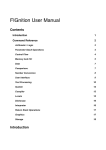
3.1 Layout
The board layout has 6 signal layers. Two of them are the power- and GND-plane.
Figure 2.1
GEMSTONE User Manual
10
www.proelec.se
Hardware
3.2 Connectors
All board connectors are shown in figure 2.1
ICE Interface
J1-1
J1-2
J1-3
J1-4
J1-5
J1-6
J1-7
J1-8
J1-9
J1-10
J1-11
J1-12
J1-13
J1-14
J1-15
J1-16
J1-17
J1-18
J1-19
J1-20
3V3
3V3
NTRST
GND
TDI
GND
TMS
GND
TCK
GND
RTCK
GND
TDO
GND
NRST
GND
NC
GND
NC
GND
Power, GPIO and CAN
J3-1
PB20
PB21
J3-2
J3-3
PB22
J3-4
PB23
J3-5
PB25
J3-6
PB26
J3-7
PB30
J3-8
PB31
J3-9
CAN-H
J3-10
CAN-L
J3-11
PB7
J3-12
PB29
J3-13
GND
J3-14
GND
J3-15
5V
J3-16
5V
GEMSTONE User Manual
11
www.proelec.se
Hardware
USART 1
J15-1
J15-2
J15-3
J15-4
TXD, Peripheral A (PA26)
RXD, Peripheral A (PA27)
RTS, Peripheral A (PA28)
CTS, Peripheral A (PA29)
USART 2
J4-1
J4-2
J4-3
J4-4
TXD, Peripheral A (PD0)
RXD, Peripheral A (PD1)
RTS, Peripheral B (PD7)
CTS, Peripheral B (PD8)
USART 3
J14-1
J14-2
J14-3
J14-4
TXD, Peripheral A (PD2)
RXD, Peripheral A (PD3)
RTS, Peripheral B (PD5)
CTS, Peripheral B (PD6)
USB Host A
J5-1
J5-2
J5-3
J5-4
GND
HDPA
HDMA
5V
USB Host B
J6-1
J6-2
J6-3
J6-4
GND
HDPB
HDMB
5V
USB Device
J11-1
J11-2
J11-3
J11-4
CNX
DDM
DDP
GND
RJ45 ETHERNET CONNECTOR
J12
Ethernet 100-base TX with two status LEDs
GEMSTONE User Manual
12
www.proelec.se
Hardware
Debug UART (DBGU)
J13-1
NC
J13-2
DTXD
J13-3
DRXD
J13-4
NC
J13-5
NC
J13-6
GND
Sound AC97
J16-1
J16-2
J16-3
J16-4
Headphone Left
Headphone Right
5V
GND
LCD – LVDS
J17-1
J17-2
J17-3
J17-4
J17-5
J17-6
J17-7
J17-8
J17-9
J17-10
J17-11
J17-12
J17-13
J17-14
J17-15
J17-16
J17-17
J17-18
J17-19
J17-20
J17-21
J17-22
J17-23
J17-24
J17-25
J17-26
J17-27
J17-28
J17-29
GND
TXOUT0TXOUT0+
TXOUT1TXOUT1+
TXOUT2TXOUT2+
GND
TXCLK0TXCLK0+
NC
NC
NC
NC
GND
NC
NC
GND
NC
NC
NC
NC
NC
NC
GND
NC
NC
NC
3V3
GEMSTONE User Manual
13
www.proelec.se
Hardware
J17-30
J17-31
J17-32
3V3
3V3
NC
LCD
J18-1
J18-2
J18-3
J18-4
J18-5
J18-6
J18-7
J18-8
J18-9
J18-10
J18-11
J18-12
J18-13
J18-14
J18-15
J18-16
J18-17
J18-18
J18-19
J18-20
J18-21
J18-22
J18-23
J18-24
J18-25
J18-26
J18-27
J18-28
J18-29
J18-30
J18-31
J18-32
J18-33
J18-34
J18-35
J18-36
J18-37
J18-38
J18-39
J18-40
5V
5V
GND
GND
3V3
3V3
Backlight ON/OFF (PB9)
GND
NC
NC
B0 (PC22)
B1 (PC23)
B2 (PC24)
B3 (PC17)
B4 (PC26)
B5 (PC27)
NC
NC
G0 (PC14)
G1 (PC15)
G2 (PC16)
G3 (PC12)
G4 (PC18)
G5 (PC19)
NC
NC
R0 (PC6)
R1 (PC7)
R2 (PC8)
R3 (PC9)
R4 (PC10)
R5 (PC11)
GND
GND
DOTCK (PC2)
VSYNC (PC0)
DATA ENABLE (PC3)
HSYNC (PC1)
3V3
3V3
GEMSTONE User Manual
14
www.proelec.se
Hardware
LCD
J19-1
J19-2
J19-3
J19-4
J19-5
J19-6
J19-7
J19-8
J19-9
J19-10
J19-11
J19-12
J19-13
J19-14
J19-15
J19-16
J19-17
J19-18
J19-19
J19-20
J19-21
J19-22
J19-23
J19-24
J19-25
J19-26
J19-27
J19-28
J19-29
J19-30
J19-31
J19-32
J19-33
J19-34
J19-35
J19-36
J19-37
J19-38
J19-39
J19-40
3V3
3V3
3V3
DOTCK (PC2)
GND
HSYNC (PC1)
GND
DATA ENABLE (PC3)
GND
NC
GND
R5 (PC11)
R4 (PC10)
R3 (PC9)
GND
R2 (PC8)
R1 (PC7)
R0 (PC6)
NC
G5 (PC19)
G4 (PC18)
G3 (PC12)
NC
G2 (PC16)
G1 (PC15)
G0 (PC14)
NC
B5 (PC27)
B4 (PC26)
B3 (PC17)
NC
B2 (PC24)
B1 (PC23)
B0 (PC22)
Power Control In (3V3)
Contrast Control (3V3 or PB9)
X-RIGHT (Touchscreen)
Y-LOW (Touchscreen)
X-LEFT (Touchscreen)
Y-UP (Touchscreen)
GEMSTONE User Manual
15
www.proelec.se
Hardware
USB
J20-1
J20-2
J20-3
J20-4
J20-5
J20-6
J20-7
J20-8
J20-9
J20-10
5V
GND
HDMA (Host A)
GND
HDPA (Host A)
HDPB (Host B)
GND
HDMB (Host B)
GND
5V
Power Supply
J21-1
J21-2
J21-3
J21-4
5V
12V (Inverter J26)
GND
GND
LCD Inverter
J26-1
J26-2
J26-3
J26-4
J26-5
J26-6
J26-7
Contrast Control
Contrast Control (PB8)
Backlight ON/OFF (PB9)
GND
GND
12V
12V
TWI (I2C)
J27-1
J27-2
J27-3
J27-4
J27-5
TWD (SDA)
TWCK (SCL)
GND
GND
5V
Touchscreen
J28-1
J28-2
J28-3
J28-4
X-LEFT
Y-LOW
X-RIGHT
Y-UP
GEMSTONE User Manual
16
www.proelec.se
Hardware
3.3 Power Supply
Connect 5V and ground (GND) from the power supply to J21.
The 12V power supply on J21 is only used if a display inverter is connected to J26.
3.4 Temperature Range
The GEMSTONE platform is available in two temperature ranges:
•
•
Standard temperature range -20° +70°C
Extreme industrial temperature range -40° +85°C
Contact Proelec for more information about the industrial variant.
GEMSTONE User Manual
17
www.proelec.se
Windows Embedded CE
4 Windows Embedded CE
4.1 General Information
The GEMSTONE platform and Windows Embedded CE 6.0 can be used in many types of
devices. One typical device can be a real-time and mission-critical industrial controller with
display support. The platform is very usable when you want to cooperate with a system in a
machine and a display is needed to interact with the user. The display is also usable in
systems there you want to show different type of sensor data. The touch screen support also
makes it very easy to interact with the system without a keypad.
4.2 Customized Windows CE Image
The Windows Embedded CE 6.0 image (kernel + BSP) is built with PB (Platform Builder), an
integrated tool in VS 2005. The image can be customized to support all type of functions and
peripherals on the board. Please contact Proelec for more information about building a
customized WinCE image.
4.2.1 Developing the Application
When you create a new application (VS project) it’s possible to use a custom image from
Proelec that has Windows Explorer and ActiveSync enabled. These features make it possible
to deploy and debug the application on the device directly from VS.
Requirements:
•
•
•
•
•
•
•
•
•
GEMSTONE hardware, PE-SBC-9263-CE-1-1A
Windows Embedded CE 6.0 image from Proelec (developer version)
A PC with Windows XP or Windows Vista
Microsoft Visual Studio 2005 + available service packs from Microsoft
Compact .NET Framework 2.0 + available service packs from Microsoft
ActiveSync enabled on the developer PC.
Platform SDK from Proelec
FlashTool from Proelec or SAM-BA from Atmel (used when programming the
DataFlash/NandFlash on the board)
USB Device cable
4.2.2 Kiosk Mode
When the application is finished and is going to be released to customer, a new WinCE
image can be made by Proelec that disables Windows Explorer and instead starts the
application (kiosk mode). The ActiveSync feature can also be disabled for higher security.
Customized start-up code in C/C++ can also be written to support application updates via
USB or other needed start-up functionality.
GEMSTONE User Manual
18
www.proelec.se
Windows Embedded CE
4.3 USB Driver
4.3.1 USB Host
USB host controllers mostly conform to one of the two standard specifications:
• OHCI
• UHCI
WinCE provides support for both this kind of controllers. All the processing is done by the
Model Device Driver (MDD) that exposes a stream driver interface. The Platform Dependent Driver
(PDD) only turns on the OHCI controller and initializes some variables (address of the controller,
system interrupt number and some objects specific to the OHCI MDD).
The driver works with USB keyboards, mouse and Mass Storage Devices.
4.3.2 USB Device
This driver is also known as an USB Function driver. Its primary purpose is to provide connectivity
between a WinCE device and a desktop PC.
The idea is that a WinCE device that contains suitable USB Function controller hardware will be
used as a serial port, mass storage device or a network device (RNDIS) when it’s connected to a
desktop PC. Essentially, there are two drivers that will be used in this type of designs:
•
•
USB Function driver
Runs on the WinCE platform and exposes the device as the wanted device to the desktop
Host-side USB driver
Runs on the desktop PC and talks to the WinCE via USB transfers.
The host driver also exposes a serial interface to the application layer so that a client
application (such as ActiveSync) running on the desktop can use it for any serial applications.
4.3.3 Interface
Communication over the USB is done by sending packets of data on the same physical line.
However USB (as a protocol) provides multiple logical lines. Those lines are called endpoints.
For more information about USB, please have a look at
http://www.beyondlogic.org/usbnutshell/usb1.htm.
GEMSTONE User Manual
19
www.proelec.se
Windows Embedded CE
4.4 Display Driver
The WinCE display driver is built on a layered architecture. The display driver is loaded by the
Graphics, Windowing and Events Subsystem (GWES) at WinCE boot. GWES calls DDI.dll that is the
default dll for the display driver. This dll exports a single function called DrvEnableDriver that returns
to the caller a pointer to an array of 27 function pointers. Those functions are called as soon as GWES
needs to display something on the device.
4.4.1 Configure the Display
When a display is configured to be used in our platform the parameters for the display and screen
are stored in the Windows registry. This feature makes it very easy to handle many types of different
displays that can be used with our platform.
Please contact Proelec for more information regarding different types of display solutions.
Example of settings in the file lcd.reg to handle a Toshiba 800x600 LVDS display:
[HKEY_LOCAL_MACHINE\System\GDI\ROTATION]
"Angle"=dword:0
[HKEY_LOCAL_MACHINE\Drivers\Display\LCDC]
"Width"=dword:320
"Height"=dword:258
"Bpp"=dword:10
"VRAMWidthInPixel"=dword:400
"VRAMHeightInPixel"=dword:400
"VRAMaddress"=dword:23e00000
"VRAMBusWidth"=dword:20
"UpperMargin"=dword:10
"LowerMargin"=dword:10
"LeftMargin"=dword:10
"RightMargin"=dword:10
"Vsync"=dword:2
"Hsync"=dword:8
"PixelClock"=dword:1312D00
;Screen width in pixel
;Screen heigth in pixel
;Bit per pixel
;Frame buffer width in pixel
;Frame buffer heigth in
;Frame buffer location.
;SDRAM has a 32-bits bus width
; Vertical Back Porch
; Vertical Front Porch
; Horizontal Back Porch
; Horizontal Front Porch
; Vertical Sync pulse width
; Horizontal sync pulse width
; Pixel clock
4.4.2 Implementation
It uses Graphics Primitive Engine (GPE) to provide a fast and reliable interface with Hardware (HW),
implements DirectDraw and provide a D3DMobile support. The driver is designed to use a rectangle
video memory space, placed either in general RAM or in specific Video RAM. The driver permits to
select which operation you want to do with HW, and which you want to do in Software (SW).
All HW calls are asynchronous and push to a FIFO. The driver support all display mode supported by
the GPE.
GEMSTONE User Manual
20
www.proelec.se
Windows Embedded CE
4.5 ADS7846 Touch screen driver
The touchpad driver is a layered native driver. Layered means that it’s composed of two layers.
The upper one is the platform independent MDD layer which implements the interface with the
system and is the functional part of the driver.
The second one is the platform dependant PDD layer that implements the interface to the hardware.
Native means that this driver has a specific interface dedicated to touch screen drivers.
4.5.1 Implementation
The ADS7846 driver uses the SPI driver for its communication, and use specific IOControls to perform
transaction between the chip and the driver. A timer forces input detection to perform the sampling
for the detection of stylus movement.
4.5.2 Calibration
At startup, a calibration application is launched allowing users to calibrate the touch screen if no
corresponding information is found in the registry. If Hive based registry is used for the device, the
calibration is only performed once at the first device boot.
Registry entries needed to load the driver at startup:
[HKEY_LOCAL_MACHINE\init]
"Launch70"="touchcalibrate1.exe"
"Depend70"=hex:14,00, 1e,00
4.6 NANDFlash Driver
The NAND flash driver is a block driver separated in two layers. The Flash Abstraction Layer (FAL) is
oriented toward the system and exposes the block driver interface. It relies on the
Flash Media Device (FMD) to access the hardware. The FAL also manages the wear leveling.
This layer is provided by Microsoft.
FMD layer handles the hardware transactions. It is provided by the OEM. It basically consists in a
set of functions to read, erase and write sectors. On our platform, the FMD has been enhanced to
add another level of translation and protection. This allows us among other things to set the Master
Boot Record (MBR) at any physical address instead of sector #0. This FMD is called the Generic FMD.
4.6.1 Integrated Support
The board has 256MB NAND Flash that can be used to store the WinCE image and to offer a logical
device that can be used to store files.
If Hive based registry is enabled, the device is storing the registry settings.
GEMSTONE User Manual
21
www.proelec.se
Windows Embedded CE
4.7 10/100 Fast Ethernet Driver
The driver supports the EmacB controller on the AT91SAM9263. This internal controller takes place
in the Ethernet stack as a MAC controller. The driver implements the Network Device Interface
(NDIS). NDIS is part of the networking architecture used in Microsoft Windows operating systems.
NDIS provides simplified miniport device driver architecture to enable communication with network
adapters using common driver interfaces.
4.8 Serial Driver
This is a layered driver. The driver is implemented as a stream driver. Stream means that this
driver is accessed through a Win32 file IO interface.
The standard stream driver functions exported by the driver are:
COM_Init
COM_Deinit
COM_Open
COM_Close
COM_Read
COM_Write
COM_Seek
COM_PowerDown
COM_PowerUp
COM_IOControl
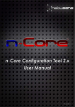
The received data is stocked in a specific class named “DmaManager”. The DMAManager is
composed of two FIFO and a current buffer, see figure 4.1.
Figure 4.1
GEMSTONE User Manual
22
www.proelec.se
Windows Embedded CE
4.8.1 Implementation
Reception buffers’ number and size and emission buffers’ size are given by the registry. There are no
software imposed limits for the size. There must be at least 4 buffers for reception. Currently the
driver uses 2 buffers for emission.
During emission, the driver uses the 2 buffers in a round robin fashion always feeding the PDC with a
filled buffer and pre filling the other one until there is no more data to send. Feeding the PDC means
updating its registers with the address and filled size of a DMA buffer containing bytes to send.
Once the PDC transmitted those bytes to the UART, it launches an empty buffer interrupt handled by
the driver by feeding the PDC with its ready buffer and by refilling the buffer just released.
During reception, the driver uses its available buffers through the DMA manager as explained at the
beginning of this chapter. When flow control is activated, the RTS line is cleared when there are more
than a half of the available buffers free and raised when there is more than three quarters of the
available buffers full.
4.8.2 Managed Code
In managed code you can use the SerialPort class that exists in Compact .NET Framework (CF). The
class supports the serial driver in WinCE. A custom driver from Proelec can also be used if you have
any problem with the SerialPort class. Contact Proelec for more information.
GEMSTONE User Manual
23
www.proelec.se
Windows Embedded CE
4.9 PIO Driver
The AT91SAM9263 Parallell Input/Output (PIO) controller can manage up to 32 fully programmable
input/output (I/O) lines. Each I/O line may be dedicated as a general-purpose I/O (GPIO) or be
assigned to a special function of an embedded peripheral. This assures effective optimization of the
pins.
Each I/O line of the PIO Controller features:
• An input change interrupt enabling level change detection on any I/O line.
• A glitch filter providing rejection of pulses lower than one-half of clock cycle.
• Multi-drive capability similar to an open drain I/O line.
• Control of the the pull-up of the I/O line.
• Input visibility and output control.
The PIO Controller also features a synchronous output providing up to 32 bits of data output in
a single write operation.
4.9.1 Implementation
The driver is implemented as a stream driver, and the driver is accessed through a Win32 file IO
interface in WinCE. A managed driver is available that can be used in CF and VS to handle different
types of functions on the available PIO pins that exists on the board.
4.9.2 Managed Driver
The driver is an assembly developed by Proelec that can be used in both C# and VB.NET.
The assembly help file is available in the distribution package, but can also be downloaded from the
Proelec homepage.
Filename:
PEWinCEGPIOLib.dll
Namespace: Proelec.Win32CE.IO.GPIO
Help file:
PEWinCEGPIOLib.chm
4.9.2.1 OutputPort
A class that represents an output pin on one of the PIO controller ports.
Constructor:
[C#]
public void OutputPort(
Port port,
UInt32 pinNumber,
bool initialState
);
Parameters:
port :
Port controller, Enum: {PA, PB, PC, PD, PE}
pinNumber: Pin number to use on the port controller
initialState: Initial state of the pin, true (high) or false (low)
Example:
Sets pin PC9 as an output and the initial state to true.
GEMSTONE User Manual
24
www.proelec.se
Windows Embedded CE
OutputPort port = new OutputPort(Port.PC, 9, true);
Properties:
State:
Returns or sets the output state
public bool State {get; set;}
Methods:
Set:
Sets the output state to true. Returns true if success, else false
public bool Set();
Clear:
Sets the output state to false. Returns true if success, else false
public bool Clear();
Read:
Reads and returns the output state
public bool Read();
Write:
Sets the output state. Returns true if success, else false
public bool Write(bool state);
Toogle:
Toggles the output state. Returns true if success, else false
public bool Toogle();
4.9.2.2 InputPort
A class that represents an input pin on one of the PIO controller ports.
Constructor:
[C#]
public void InputPort(
Port port,
UInt32 pinNumber,
);
public void InputPort(
Port port,
UInt32 pinNumber,
bool pullUp,
bool glitchFilter
);
Parameters:
port :
pinNumber:
pullUp:
glitchFilter:
Port controller, Enum: {PA, PB, PC, PD, PE}
Pin number to use on the port controller
Enables or disables the internal pull-up resistor, default = true
Enables or disables the internal glitch filter, default = false
Example:
Sets pin PB20 as an input.
InputPort port = new InputPort(Port.PB, 20);
GEMSTONE User Manual
25
www.proelec.se
Windows Embedded CE
Properties:
State:
Returns the input pin state
public bool State {get;}
Pullup:
Returns or Sets the internal pull-up resistor enable property
public bool Pullup {get; set;}
GlitchFilter: Returns or Sets the internal glitch filter enable property
public bool GlitchFilter {get; set;}
Methods:
Read:
Reads and returns the input state
public bool Read();
4.9.2.3 InputEventPort
A class that represents an event driven input pin on one of the PIO controller ports.
Constructor:
[C#]
public void InputEventPort(
Port port,
UInt32 pinNumber,
);
public void InputEventPort(
Port port,
UInt32 pinNumber,
bool pullUp,
bool glitchFilter
CEThreadPriority priority,
bool enabled
);
Parameters:
port :
pinNumber:
pullUp:
glitchFilter:
priority:
enabled:
Port controller, Enum: {PA, PB, PC, PD, PE}
Pin number to use on the port controller
Enables or disables the internal pull-up resistor, default = true
Enables or disables the internal glitch filter, default = false
Windows CE thread priority, default = CEThreadPriority.Normal
Enables or disables event handler on changed input state, default = true
Example:
Sets pin PB20 as an event driven input.
InputEventPort port = new InputEventPort(Port.PB, 20);
GEMSTONE User Manual
26
www.proelec.se
Windows Embedded CE
Properties:
State: Returns the input pin state
public bool State {get;}
Enabled: Enables or disables event handler on changed input state
public bool Enabled {get; set;}
Methods:
Read:
Reads and returns the input state
public bool Read();
WndProc: The window process message method
protected override void WndProc(
ref Message msg
);
Dispose:
The dispose method used to free allocated resources in WinCE
new public void Dispose();
Events:
StateChanged:
Event is trigged when the state is changed on the selected pin
public event System.EventHandler StateChanged;
StateEventArguments: The state event argument constructor
public void StateEventArgs(
bool state
);
PortState property: Returns the current pin state
public bool PortState {get;}
4.9.2.4 WakeupPort
A class that represents a wake-up pin on one of the PIO controller ports.
The selected pin can be used to wake-up the system after suspending WinCE.
Constructor:
[C#]
public void WakeupPort(
Port port,
UInt32 pinNumber,
);
public void WakeupPort(
Port port,
UInt32 pinNumber,
bool pullUp,
bool glitchFilter
);
Parameters:
port :
Port controller, Enum: {PA, PB, PC, PD, PE}
pinNumber: Pin number to use on the port controller
GEMSTONE User Manual
27
www.proelec.se
Windows Embedded CE
pullUp:
glitchFilter:
Enables or disables the internal pull-up resistor, default = true
Enables or disables the internal glitch filter, default = false
Example:
Register PC4 as an wake-up pin.
WakeupPort port = new WakeupPort(Port.PC, 4);
Properties:
State:
Returns the wake-up pin state
public bool State {get;}
Pullup:
Returns or Sets the internal pull-up resistor enable property
public bool Pullup {get; set;}
GlitchFilter: Returns or Sets the internal glitch filter enable property
public bool GlitchFilter {get; set;}
Methods:
Read:
Reads and returns the wake-up state
public bool Read();
Remove:
Unregisters the pin as an wake-up
public bool Remove();
4.9.2.5 PeripheralPort
A class that is used to set a pin on one of the PIO controller ports to one of the peripheral functions,
A or B.
Constructor:
[C#]
public void PeripheralPort(
Port port,
UInt32 pinNumber,
PeripheralGroup peripheral
);
public void PeripheralPort(
Port port,
UInt32 pinNumber,
PeripheralGroup peripheral,
bool pullUp,
bool openDrain
);
Parameters:
port :
Port controller, Enum: {PA, PB, PC, PD, PE}
pinNumber: Pin number to use on the port controller
peripheral : Peripheral function, Enum: {A, B}
GEMSTONE User Manual
28
www.proelec.se
Windows Embedded CE
pullUp:
openDrain:
Enables or disables the internal pull-up resistor, default = false
Enables or disables the internal open drain transistor, default = true
Example:
Set pin PD0 to peripheral function TXD1 (USART 1).
PeripheralPort port = new PeripheralPort(Port.PD, 0, PeripheralGroup.A);
Properties:
State:
Returns the pin state
public bool State {get;}
Methods:
Read:
Reads and returns the wake-up state
public bool Read();
4.9.2.6 PWMPort
A class that represents a PWM-channel.
Constructor:
[C#]
public void PWMPort(
PWMChannel channel,
UInt32 frequency,
UInt32 dutyCycle
);
Parameters:
channel :
PWM channel, Enum: {PWC0, PWC1, PWC2, PWC3}
frequency:
The frequency in Hz
dutyCycle :
The duty cycle in % (0-100)
Example:
Using PC28 as PWM channel 0, frequency 1KHz and 50% duty cycle.
PWMPort port = new PWMPort(PWMChannel.PWC0, 1000, 50);
Methods:
Config:
Sets frequency and duty cycle on current PWM channel. Returns true on success
public bool Config(
UInt32 frequency,
UInt32 dutyCycle
);
GEMSTONE User Manual
29
www.proelec.se
Windows Embedded CE
Start:
Starts the PWM channel. Returns true on success, else false
public bool Start();
Stop:
Stops the PWM channel. Returns true on success, else false
public bool Stop();
4.10 CAN Driver
The AT91SAM9263 Controller Area Network (CAN) controller provides all the features required to
implement the serial communication protocol CAN defined by Robert Bosch GmbH, the CAN
specification as referred to by
ISO/11898A (2.0 Part A and 2.0 Part B) for high speeds and ISO/11519-2 for low speeds.
The CAN Controller is able to handle all types of frames (Data, Remote, Error and Overload) and
achieves a bit rate of 1 Mbit/sec.
CAN controller accesses are made through configuration registers. 16 independent message
objects (mailboxes) are implemented. Any mailbox can be programmed as a reception buffer block
(even non-consecutive buffers). For the reception of defined messages, one or several message
objects can be masked without participating in the buffer feature. An interrupt is generated when
the buffer is full. According to the mailbox configuration, the first message received can be locked in
the CAN controller registers until the application acknowledges it, or this message can be discarded
by new received messages. Any mailbox can be programmed for transmission. Several transmission
mailboxes can be enabled in the same time. A priority can be defined for each mailbox
independently. The CAN block diagram is shown in figure 4.2
GEMSTONE User Manual
30
www.proelec.se
Windows Embedded CE
Figure 4.2
4.10.1 Implementation
The driver is implemented as a stream driver, and the driver is accessed through a Win32 file IO
interface in WinCE. A managed driver is available that can be used in CF and VS to handle CAN
messages.
4.10.2 Managed Driver
The driver is an assembly developed by Proelec that can be used in both C# and VB.NET.
The assembly help file is available in the distribution package, but can also be downloaded from the
Proelec homepage.
Filename:
PEWinCECANLib.dll
Namespace: Proelec.Win32CE.IO.CAN
Help file:
PEWinCECANLib.chm
4.10.2.1 CANMessage
A class that represents a CAN message.
Constructor:
[C#]
public void CANMessage();
public void CANMessage(
byte[] message,
int position
);
public void CANMessage(
UInt32 identifier,
UInt32 length,
byte[] data
);
Parameters:
message :
position:
identifier :
length:
data:
Properties:
Identifier:
A byte array of CANMessage objects
Can message position in the byte array of CANMessage objects
The message identifier, 11/29 bits
Length of data, 1-8 bytes
A byte array of message data, max 8 bytes
Returns or sets the message identifier
public UInt32 Identifier {get; set;}
Data:
Returns or sets the array of message data, max 8 bytes
public byte[] Data {get; set;}
Length:
Returns or sets the length of message data, 1-8 bytes
public UInt32 Length {get; set;}
GEMSTONE User Manual
31
www.proelec.se
Windows Embedded CE
NumOfBytes:
Returns the object size in bytes
public static int NumOfBytes {get;}
Methods:
ToBytes: Returns the message object as an byte array
public byte[] ToBytes();
4.10.2.2 Config
A class used to configure the CAN controller.
Constructor:
[C#]
public void Config();
Methods:
SetBaudrate: Sets the baudrate, max 1 Mbits/sec
public void SetBaudRate(
BaudRate baudRate
);
baudRate: enum { BITRATE_50, BITRATE_100, BITRATE_125, BITRATE_250, BITRATE_500,
BITRATE_800, BITRATE_1000}
SetFrameMode Sets the frame mode
public void SetFrameMode(
FrameMode frameMode
);
frameMode: enum { Standard, Extended}
SetWriteInterval: Sets the minimal time between two sent messages, 0 = Disabled
public void SetWriteInterval(
int milliSeconds
);
SetPriority256: Sets the CAN interrupt service thread (IST) priority (0-256), 0 is highest
public void SetPriority256(
int priority
);
GEMSTONE User Manual
32
www.proelec.se
Windows Embedded CE
4.10.2.3 TransmitMailbox
A class that represents a mailbox configured for transmission of CAN messages.
Constructor:
[C#]
public void TransmitMailbox(
int mailbox,
);
public void TransmitMailbox(
int mailbox,
int identifier
);
Parameters:
mailbox :
The mailbox index to use, 0-15
identifier:
Can message identifier, 11/29 bits
Properties:
Enabled:
Returns or sets the mailbox enabled property
public bool Enabled {get; set;}
Identifier:
Returns or sets the mailbox identifier
public int Identifier {get; set;}
IsOpen: Returns true if mailbox is opened, else false
public bool IsOpen {get;}
Methods:
Open:
Opens the mailbox
public void Open();
public void Open(
bool enabled
);
Close:
Closing the mailbox
public void Close();
Write:
Writes CAN message
public int Write(
CANMessage message
);
message: CANMessage object to write
public int Write(
byte[] buffer
);
buffer: Byte array of CANMessage objects to write
GEMSTONE User Manual
33
www.proelec.se
Windows Embedded CE
4.10.2.4 SimpleReceptionMailbox
A class that represents a single mailbox configured for reception of CAN messages.
Using this type of mailbox in real-time systems is not recommended. The mailbox can be overloaded
with incoming messages. The ChainedReceptionMailbox object should be used in that kind of
systems.
Constructor:
[C#]
public void SimpleReceptionMailbox(
int mailbox,
);
public
int
int
int
);
void SimpleReceptionMailbox(
mailbox,
acceptanceCode,
acceptanceMask,
public void SimpleReceptionMailbox(
int mailbox,
int maxBufferSize
);
public
int
int
int
int
);
void SimpleReceptionMailbox(
mailbox,
acceptanceCode,
acceptanceMask,
maxBufferSize
Parameters:
mailbox :
The mailbox index to use, 0-15
acceptanceCode : The mailbox acceptance code
acceptanceMask : The mailbox acceptance mask
maxBufferSize:
The maximal number of CANMessage objects that can be stored in the buffer
Properties:
Enabled:
Returns or sets the mailbox enabled property
public bool Enabled {get; set;}
AcceptanceCode: Returns or sets the mailbox acceptance code
public int AcceptanceCode {get; set;}
AcceptanceMask: Returns or sets the mailbox acceptance mask
public int AcceptanceMask {get; set;}
Count: Returns the number of messages in mailbox buffer
public int Count {get;}
GEMSTONE User Manual
34
www.proelec.se
Windows Embedded CE
IsOpen: Returns true if mailbox is opened, else false
public bool IsOpen {get;}
Methods:
Open:
Opens the mailbox
public void Open();
public void Open(
bool enabled
);
Close:
Closing the mailbox
public void Close();
Clear:
Clears all the messages in the mailbox buffer
public void Clear();
Read:
Reads a CAN message
public CANMessage Read();
public int Read(
byte[] buffer,
int count
);
buffer: Byte array of CAN messages to write
count: Number of messages in buffer
Events:
OnMessageRecieved: Event is trigged when a new message arrives in the buffer
public event MessageRecievedEventHandler OnMessageRecieved;
MessageRecievdArgs: The event argument constructor
public void MessageRecievedArgs(
CANMessage message
);
Message property: Returns the CANMessage object
public CANMessage Message {get;}
GEMSTONE User Manual
35
www.proelec.se
Windows Embedded CE
4.10.2.5 ChainedReceptionMailbox
A class that represents two or more chained mailboxes configured for reception of CAN messages.
This type of mailbox is recommended to use in real-time systems.
Constructor:
[C#]
public void ChainedReceptionMailbox(
int startMailbox,
int numOfMailboxes
);
public
int
int
int
int
);
void ChainedReceptionMailbox(
mailbox,
numOfMailboxes,
acceptanceCode,
acceptanceMask,
public
int
int
int
);
void ChainedReceptionMailbox(
mailbox,
numOfMailboxes,
maxBufferSize
public
int
int
int
int
int
);
void ChainedReceptionMailbox(
mailbox,
numOfMailboxes,
acceptanceCode,
acceptanceMask,
maxBufferSize
Parameters:
mailbox :
numOfMailboxes :
acceptanceCode :
acceptanceMask :
maxBufferSize:
Properties:
Enabled:
The start mailbox index to use, 0-15
The number of mailboxes to chain
The mailbox acceptance code
The mailbox acceptance mask
The maximal number of CANMessage objects that can be stored in the buffer
Returns or sets the mailbox enabled property
public bool Enabled {get; set;}
AcceptanceCode: Returns or sets the mailbox acceptance code
public int AcceptanceCode {get; set;}
AcceptanceMask: Returns or sets the mailbox acceptance mask
public int AcceptanceMask {get; set;}
Count: Returns the number of messages in mailbox buffer
public int Count {get;}
GEMSTONE User Manual
36
www.proelec.se
Windows Embedded CE
IsOpen: Returns true if mailbox is opened, else false
public bool IsOpen {get;}
Methods:
Open:
Opens the mailbox
public void Open();
public void Open(
bool enabled
);
Close:
Closing the mailbox
public void Close();
Clear:
Clears all the messages in the mailbox buffer
public void Clear();
Read:
Reads a CAN message
public CANMessage Read();
public int Read(
byte[] buffer,
int count
);
buffer: Byte array of CAN messages to write
count: Number of messages in buffer
Events:
OnMessageRecieved: Event is trigged when a new message arrives in the buffer
public event MessageRecievedEventHandler OnMessageRecieved;
MessageRecievdArgs: The event argument constructor
public void MessageRecievedArgs(
CANMessage message
);
Message property: Returns the CANMessage object
public CANMessage Message {get;}
GEMSTONE User Manual
37
www.proelec.se
Windows Embedded CE
4.11 TWI/I2C Driver
The Two-wire Interface (TWI) interconnects components on a unique two-wire bus, made up of
one clock line and one data line with speeds of up to 400 Kbits per second, based on a byte-oriented
transfer format. It can be used with any Atmel Two-wire Interface bus Serial EEPROM and
Inter-Integrated Circuit (I2C) compatible device such as Real Time Clock (RTC), Dot Matrix/Graphic
LCD Controllers and Temperature Sensor, to name but a few. The TWI is programmable as master
transmitter or master receiver with sequential or single-byte access. A configurable baud rate
generator permits the output data rate to be adapted to a wide range of core clock frequencies.
Table 4.1 lists the compatibility level of the Atmel Two-wire Interface and a full I2C compatible device.
Figure 4.3 shows the TWI block diagram.
Table 4.1
I2C Standard
Standard Mode Speed (100 KHz)
Fast Mode Speed (400 KHz)
7 or 10 bits Slave Addressing
START BYTE, START + b000000001 + Ack + Sr
Repeated Start (Sr) Condition
ACK and NACK Management
Slope control and input filtering (Fast mode)
Clock strectching
Atmel TWI
Supported
Supported
Supported
Not Supported
Not Fully Supported
Supported
Supported
Supported
Figure 4.3
4.11.1 Implementation
The driver is implemented as a stream driver, and the driver is accessed through a Win32 file IO
interface in WinCE. A managed driver is available that can be used in CF and VS to handle the I2C bus.
GEMSTONE User Manual
38
www.proelec.se
Windows Embedded CE
4.11.2 Managed Driver
The driver is an assembly developed by Proelec that can be used in both C# and VB.NET.
The assembly help file is available in the distribution package, but can also be downloaded from the
Proelec homepage.
Filename:
PEWinCEI2CLib.dll
Namespace: Proelec.Win32CE.IO.I2C
Help file:
PEWinCEI2CLib.chm
4.11.2.1 I2CBus
A class used to handle the TWI/I2C bus.
Constructor:
[C#]
public void I2CBus();
public void I2CBus(
UInt32 clockRate
);
Parameters:
clockRate :
The bus clock rate. Default = 100K.
Methods:
SetTransferRate: Sets the clock rate
public void SetTransferRate(UInt32 clockRate);
Read:
Reads data from a device connected to the bus, exceptions are thrown on errors
public void Read(
UInt32 deviceAddr,
UInt32 internalAddr,
InternalAddressSize internalAddrSize,
bool disableInterrupt,
byte[] buffer,
UInt32 bytesToRead
);
Parameters:
deviceAddr :
internalAddr :
internalAddrSize :
disableInterrupt :
buffer:
bytesToRead :
Device address
Internal address
Internal address size, enum: {NoAddress, OneByte, TwoByte, ThreeByte}
Interrupt Enable/Disable while reading
Data buffer
Number of bytes to read
GEMSTONE User Manual
39
www.proelec.se
Windows Embedded CE
Write: Write data to a device connected to the bus, exceptions are thrown on errors
public void Write(
UInt32 deviceAddr,
UInt32 internalAddr,
InternalAddressSize internalAddrSize,
bool disableInterrupt,
byte[] buffer,
UInt32 bytesToWrite
);
Parameters:
deviceAddr :
internalAddr :
internalAddrSize :
disableInterrupt :
buffer:
bytesToWrite :
Device address
Internal address
Internal address size, enum: {NoAddress, OneByte, TwoByte, ThreeByte}
Interrupt Enable/Disable while writing
Data buffer
Number of bytes to write
GEMSTONE User Manual
40
www.proelec.se
Windows Embedded CE
4.12 SPI Driver
The Serial Peripheral Interface (SPI) circuit is a synchronous serial data link that provides
communication with external devices in Master or Slave Mode. It also enables communication
between processors if an external processor is connected to the system.
The Serial Peripheral Interface is essentially a shift register that serially transmits data bits to
other SPIs. During a data transfer, one SPI system acts as the “master”' which controls the
data flow, while the other devices act as “slaves'' which have data shifted into and out by the
master. Different CPUs can take turn being masters (Multiple Master Protocol opposite to Single
Master Protocol where one CPU is always the master while all of the others are always
slaves) and one master may simultaneously shift data into multiple slaves. However, only one
slave may drive its output to write data back to the master at any given time.
A slave device is selected when the master asserts its NSS signal. If multiple slave devices
exist, the master generates a separate slave select signal for each slave (NPCS).
The SPI system consists of two data lines and two control lines:
• Master Out Slave In (MOSI): This data line supplies the output data from the master shifted
into the input(s) of the slave(s).
• Master In Slave Out (MISO): This data line supplies the output data from a slave to the
input of the master. There may be no more than one slave transmitting data during any
particular transfer.
• Serial Clock (SPCK): This control line is driven by the master and regulates the flow of the
data bits. The master may transmit data at a variety of baud rates; the SPCK line cycles
once for each bit that is transmitted.
• Slave Select (NSS): This control line allows slaves to be turned on and off by hardware
Block Diagram:
Figure 4.4
GEMSTONE User Manual
41
www.proelec.se
Windows Embedded CE
Application Block Diagram: Single Master/Multiple Slave Implementation
Figure 4.5
4.12.1 Implementation
The driver is implemented as a stream driver, and the driver is accessed through a Win32 file IO
interface in WinCE.
4.12.2 Managed Driver
A public managed SPI driver is not available. Please contact Proelec to get more information about
how to get a custom driver that you can use in VS.
GEMSTONE User Manual
42
www.proelec.se
Linux
5 Linux
5.1 General Information
The GEMSTONE platform can be used with an embedded Linux distribution.
Proelec can develop a custom Linux image. The image can be customized to support all type
of functions and peripherals on the board. Please contact Proelec for more information
about building a customized Linux image.
GEMSTONE User Manual
43
www.proelec.se
FlashTool
6 FlashTool
6.1 General Information
FlashTool is a program used to program both the DataFlash and NandFlash memory on the board.
The tool exists only for use with the WinCE distribution from Proelec, but can be customized for
other distributions or environments.
The program uses the SAM Boot Assistant (SAM-BA) Application Program Interface (API) from Atmel
to interact with the board memories.
6.2 Windows CE
The program FlashTool AT91SAM9263CE is distributed with the Windows CE image, and is
used to put the FirstBoot, EBoot and OS-image into the board memories.
DataFlash:
NandFlash:
FirstBoot and EBoot
OS-image
6.2.1 Program GUI
Figure 6.1
GEMSTONE User Manual
44
www.proelec.se
FlashTool
6.2.2 Install SAM-BA Windows Driver
If the distribution package AT91-ISP 1.1X from Atmel already is installed on your computer, you don’t
need to install the custom FlashTool driver from Proelec if the version of the package is
1.10 or higher. If you have an older version you must uninstall the AT91-ISP 1.1X package before
installing the driver from Proelec.
If you want to install the FlashTool driver from Proelec, just go to the Tools menu in the program and
select install driver, See figure 6.2. The driver is not Microsoft certified, so you must accept the
installation when the acceptance dialog appears on the screen.
When installation of the driver is finished the board can be started up in SAM-BA (programming)
mode, see 6.2.3.
Figure 6.2
6.2.3 Starting up the board in SAM-BA Mode
Hold down button U6 (see figure 2.1) while switching on the board power supply (5V).
If you hear a sound from the PC, the board should be in SAM-BA (programming) mode.
If you have problems to set the board in programming mode, check that the device exists in the
Windows device manager. If you have installed the Proelec driver you should look in
the Ports (COM and LPT) category of devices, and if you have installed the AT91-ISP 1.1X package you
should look in USB devices.
GEMSTONE User Manual
45
www.proelec.se
FlashTool
6.2.4 Programming the DataFlash
The DataFlash memory is programmed in two phases. First phase is to put the FirstBoot file into the
memory and second phase the EBoot file. Figure 6.3 shows the controls used while programming the
DataFlash.
Figure 6.3
FirstBoot:
Select the FirstBoot file and then use the Write FirstBoot button to put the file into memory.
EBoot:
Select the EBoot file and then use the Write EBoot button to put the file into memory.
6.2.5 Erasing the DataFlash
The DataFlash memory can be erased if you press the Erase All button in the DataFlas section of the
program, see figure 6.4. To re-enable booting the OS, you must program the FirstBoot and EBoot file.
The EBoot settings are also erased, so you must load Default Settings, edit and save the settings to
successfully boot the OS again.
Figure 6.4
6.2.6 Programming the NandFlash
The NandFlash memory is programmed by putting the OS-image file into the memory.
Figure 6.5 shows the controls to use while programming. Select the OS-image file and then use the
Write Image button to put the file into memory. The EBoot field Flash Image Size is automatically
changed, so remember to save the new setting to DataFlash if the image size is different.
Figure 6.5
GEMSTONE User Manual
46
www.proelec.se
FlashTool
6.2.7 Erasing the NandFlash
The NandFlash memory can be erased if you press the Erase All button, see figure 6.5.
To re-enable booting the OS, you must re-program the OS-image file into the NandFlash memory.
6.2.8 EBoot Settings
To load the EBoot default settings into the program fields, use the Set Defaults button. Figure 6.6
shows the controls to use when handling the settings.
Use the Read Settings button to load data from the DataFlash memory and Write Settings button to
store the data back into the memory.
Figure 6.6
6.2.9 Programming Status
Current programming status and errors are shown in the list box to the right, see figure 6.7.
Figure 6.7
6.3 Linux
A FlashTool program for a custom embedded Linux distribution can be made by Proelec.
Please contact Proelec for more information.
GEMSTONE User Manual
47
www.proelec.se
Appendix A: Schematics
7 Appendix A: Schematics
GEMSTONE User Manual
48
www.proelec.se
Appendix A: Schematics
GEMSTONE User Manual
49
www.proelec.se
Appendix A: Schematics
GEMSTONE User Manual
50
www.proelec.se
Appendix A: Schematics
GEMSTONE User Manual
51
www.proelec.se
Appendix A: Schematics
GEMSTONE User Manual
52
www.proelec.se
Appendix A: Schematics
GEMSTONE User Manual
53
www.proelec.se
Appendix A: Schematics
GEMSTONE User Manual
54
www.proelec.se
Appendix A: Schematics
GEMSTONE User Manual
55
www.proelec.se
Appendix A: Schematics
GEMSTONE User Manual
56
www.proelec.se
Appendix A: Schematics
GEMSTONE User Manual
57
www.proelec.se
Revision History
8 Revision History
Version
1.0
Comments
Document start
GEMSTONE User Manual
Date
2009-04-17
58
www.proelec.se
References
9 References
Atmel. (2009). AT91SAM9263 Resources page.
http://www.atmel.com/dyn/products/product_card.asp?part_id=4056. (2009-04-17).
Atmel. (2009). AT91SAM9263 Preliminary.
http://www.atmel.com/dyn/resources/prod_documents/doc6249.pdf. (2009-04-17).
GEMSTONE User Manual
59
www.proelec.se