1
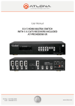
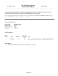
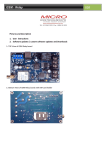
AUTO TRANSFER SWITCH (ATS)
USER MANUAL
POWER MASTER
AUTO TRANSFER SWITCH (ATS)
Introduction
Appliances running on 230 volts are automatically switched between a Master AC source
and Slave AC source. The total switching time is less than 10 ms. To give but two
examples: if the Master IN fails, then the microwave oven's clock keeps running and any
data in the computer is preserved.
The ATS can be used with any up to a capacity of 40A.
Operation
The ATS is situated between a Master AC source and Slave AC source. If the voltage
level or the frequency of the Master Input varies, then the ATS switches to the Slave
Input. Once the Master’s supply has remained continuously stable for 30 seconds, the
ATS switches back. In this way, the appliances are continuously protected against
damage from voltage drops. The ATS is suitable for modern appliances such as video
recorders, computers and microwave ovens, devices that cannot stand up (well) to a drop
in voltage. The ATS automatic switch box can be used with any type of inverter; the best
results, however, are obtained with an inverter from Power Master Technology Series.
Application of Slave Input and Master Input
The source selection of Slave and Master depends on user’s environment, equipment and
usage and typically, mains/generators is used as priority source to be Master Input and
DC/AC inverters as alternate source to be Slave Input. The usage of DC/AC inverters as
priority Main Input and mains/generator as alternate Slave Input are also applicable.
Installation
· Install the ATS in a dry, well-ventilated area. The ATS may be mounted on the table,
using the three holes in the rear of the casing to put in the Master input cable, Slave
input cable, AC output cable and opening the entry on the upper casing to tighten the
cables on the terminals with screws.
· The input cables from the generator, mains and the inverter, any AC source, and the
output cables to the appliances should be connected to the terminals according to
Figure 1.
· The Master Input socket needs to be protected against current levels higher than 20/40
amp.
· The Slave Input socket needs to be protected against current levels higher than 20/40
amp.
L
N
L
N2
PE
)
E
V
A
L
S
(
INPUT1
(M ASTER)
PE
INPUT2
Figure 1 Connection Terminal
1
L
N
OUTPUT
PE
Front Panel
LED Indicators
AC OUTPUT
POWER
MASTER
POWER
SLAVE
OUTPUT MASTER
OUTPUT SLAVE
AC
OUTPUT
OUTPUT
MASTER
OUTPUT
SLAVE
POWER
MASTER
POWER
SLAVE
The Master power within the specified voltage and frequency
has been input.
The Slave Input power within the specified voltage and
frequency has been input.
The appliances are running on the Master source as a priority.
The appliances are running on the Slave source when the Master
source fails.
The AC output has been successfully supplied from either
POWER MASTER or POWER SLAVE.
2
Rear Panel
PM-ATS-20A
PM-ATS-40A
3
Specifications
Model No.
Maximum switched capacity
Master Input
Voltage
Frequency
Slave Input
Voltage
Frequency
Thresholds for output of Master
For switching to Slave
For switching to Master
Continuous stability interval
Dimensions (H x W x D)
PM-ATS-20A
20A
PM-ATS-40A
40A
190-240 volts
50Hz/60Hz
(selectable)
190-240 volts
50Hz/60Hz
(selectable)
0-240 volts
Not monitored
0-240 volts
Not monitored
180 volts
188 volts
30 sec
95 x 130 x 220 mm
180 volts
188 volts
30 sec
95 x 130 x 255 mm
4
5
6
7