1
RMX 1000 User Guide
Version 1.1
Copyright © 2007 Polycom, Inc.
All Rights Reserved
Catalog No. 3150-16966-001
Version 1.1
Proprietary and Confidential
The information contained herein is the sole intellectual property of Polycom, Inc. No distribution, reproduction or unauthorized
use of these materials is permitted without the expressed written consent of Polycom, Inc. Information contained herein is subject
to change without notice and does not represent commitment of any type on the part of Polycom, Inc. Polycom and Accord are
registered trademarks of Polycom, Inc.
Notice
While reasonable effort was made to ensure that the information in this document was complete and accurate at the time of
printing, Polycom, Inc., cannot assume responsibility for any errors. Changes and/or corrections to the information contained in
this document may be incorporated into future issues.
Regulatory Notices
United States Federal Communication
CE & UL Mark
Commission (FCC)
Part 15: Class A Statement. This equipment has
been tested and found to comply with the limits for
a Class A digital device, pursuant to Part 15 of the
FCC Rules. Test limits are designed to provide
reasonable protection against harmful interference
when the equipment is operated in a commercial
environment. This equipment generates uses and
can radiate radio-frequency energy and, if not
installed and used in accordance with the
instruction
manuals,
may
cause
harmful
interference to radio communications. Operation of
this equipment in a residential area is likely to
cause harmful interference, in which case the user
will be required to correct the interference at his or
her own expense.
Polycom Inc., declares that the Polycom
RSS2000 is in conformity with the following
relevant harmonized standards:
EN 60950-1:2001+A11:2004
EN 55022:2006
EN 55024:1998/A1:2001/A2:2003
EN 61000-3-2:2006
EN 61000-3-3:1995/A1:2001/A2:2005
UL Listed (USA)
CUL Listed (Canada)
Following the provisions of the Council Directive
1999/CE on radio and telecommunication
terminal equipment and the recognition of its
conformity.
Compliant with European Battery Directive 2006/66/EC
To comply with the European Battery Directive 2006/66/EC, dispose of weak and worn out batteries in
accordance with local and national regulations.
Polycom RMX 1000 User Guide
Table of Contents
Table of Contents············································································ i
System Overview ········································································ 1-1
RMX 1000 ········································································ 1-1
RMX 1000 Main Features ···················································· 1-1
Video Display······························································· 1-1
LPR ············································································ 1-1
IVR-Enabled Conferencing·············································· 1-2
Recording Link ····························································· 1-2
Conferencing Capabilities and Options······························ 1-2
User Interfaces······························································ 1-3
Full Integration with SE 200············································· 1-3
First Time Installation and Configuration································· 2-1
Hardware Installation and Setup ·········································· 2-1
Configuration Preparations ················································· 2-1
Obtaining Network Information······································· 2-1
Obtaining Product Activation Key ···································· 2-2
First Time Configuration····················································· 2-1
Connecting PC to RMX 1000 ············································ 2-1
Logging in to Web UI····················································· 2-2
Modifying the Default IP Address ···································· 2-3
Configuring Other Network Options (Optional) ·················· 2-4
Basic Operation ·········································································· 3-1
RMX 1000 Screen Components············································· 3-1
User Rights ·································································· 3-1
Pane Layout ································································· 3-2
Common Operations······················································ 3-4
Starting a Conference ························································· 3-5
Starting a Conference from the Conferences Pane ················ 3-6
Starting a Conference Using the Remote Control ················· 3-7
Connecting to a Conference – Dialing Methods ······················· 3-8
Dial-in – RMX 1000 Registered to GK ································ 3-8
Dial-in – RMX 1000 Not Registered to GK ·························· 3-9
i
Table of Contents
Conference Profiles···································································· 4-1
Defining a Profile ······························································ 4-2
General Settings ···························································· 4-3
Video Quality ······························································· 4-4
Video Settings ······························································ 4-6
Conference Skin ···························································· 4-8
Conference Recording ···················································· 4-8
Modifying a Profile···························································· 4-9
Deleting a Profile······························································· 4-9
Setting a Default Profile ······················································ 4-9
Recording Link············································································ 5-1
Recording Setup································································ 5-1
General Settings ···························································· 5-2
DTMF Code Setting ······················································· 5-2
Recording Control ····························································· 5-3
Meeting Rooms ··········································································· 6-1
Creating a Meeting Room ··············································· 6-1
Modifying a Meeting Room············································· 6-4
Deleting a Meeting Room················································ 6-4
Reservations ··············································································· 7-1
Adding a Reservation························································· 7-1
Reserving a One-Time Conference ···································· 7-2
Reserving a Daily Conference ·········································· 7-3
Reserving a Weekly Conference ······································· 7-3
Reserving a Monthly Conference ······································ 7-4
Modifying a Reservation····················································· 7-5
Deleting a Reservation························································ 7-5
Address Book ············································································· 8-1
Adding a Participant to the Address Book ······························ 8-1
Creating a Participant in the Address Book························· 8-1
Adding a Participant from an Ongoing Conference ·············· 8-4
Defining a Participant Group ··············································· 8-5
Modifying a Participant/Group ··········································· 8-5
Deleting a Participant/Group ·············································· 8-5
Conference/Participant Monitoring ··········································· 9-1
Conference Monitoring······················································· 9-1
ii
Polycom RMX 1000 User Guide
Viewing Conferences List Pane ············································ 9-1
Viewing Conference Parameters··········································· 9-2
Conference Control···························································· 9-3
Participant Monitoring ······················································· 9-7
Viewing Participant List ····················································· 9-7
Viewing Participant Properties············································· 9-8
Participant Control ···························································· 9-9
Users and Connections···························································· 10-1
User List·········································································10-2
Defining New User ···························································10-2
Deleting User ··································································10-3
Modifying User Password··················································10-3
Viewing User Connection ··················································10-4
Network Service········································································ 11-1
IP Setting ········································································11-1
Advanced Setting ·····························································11-3
Routers ······································································11-4
Gatekeeper ·································································11-4
QoS ···········································································11-5
Ports··········································································11-7
Email ·········································································11-7
IVR Service ················································································ 12-1
Default IVR Information ····················································12-1
Customizing IVR Information·············································12-3
Replace the IVR information···········································12-3
Recording an Audio Message ·········································12-3
CDR ···························································································· 13-1
CDR Files ·······································································13-1
Viewing CDR Records·······················································13-2
Saving CDR Records ·························································13-3
RMX Utilities·············································································· 14-1
System Alerts ··································································14-1
H.323 Link ······································································14-2
System Time····································································14-2
Customization ·································································14-3
Modifying Language·····················································14-4
iii
Table of Contents
Setting System Name ····················································14-4
Security Setting ································································14-4
Device Upgrade ·······························································14-5
Product Activation ···························································14-7
Log Management ·····························································14-8
Software Management·······················································14-9
Backup Configuration ···················································14-9
Restoring Configuration ·············································· 14-10
Signaling and Hardware Monitoring ······································· 15-1
Signaling Monitoring ························································15-1
Hardware Monitor ···························································15-2
Personal Conference Manager (PCM)····································· 16-1
Introduction to PCM and Operations ···································16-2
Creating a Conference ·······················································16-4
Entering an Existing Conference··········································16-8
Conference Control for Regular Participants ························ 16-10
Click & View ····························································· 16-10
Camera Control ························································· 16-12
Video Force······························································· 16-13
Chairperson Conference Control ······································· 16-14
Invite Participant························································ 16-16
Participant mute/status··············································· 16-16
Drop Participant ························································ 16-18
Terminate Conference ················································· 16-19
Appendix A - Connection Failure Diagnosis ·························· 17-1
Appendix B: Telnet/Terminal Commands ······························· 18-1
HyperTerminal Parameters ················································18-1
Login ·············································································18-1
Command Introduction ·····················································18-2
Appendix C: Glossary ······························································ 19-1
iv
1
System Overview
This chapter will serve as a brief introduction to the RMX 1000 system and its
major functions and features. The subsequent chapters provide more details
to attend, manage, and monitor conferences through the RMX 1000 system,
and on maintaining the device.
RMX 1000
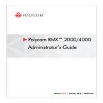
The Polycom real-time media conferencing platform (RMX 1000) is a
high-value multipoint platform for small IP networks or remote locations on
large IP networks.
The Polycom RMX 1000 provides the following features:
•
All-in-one box is easy to install, configure, and manage
•
Provides high quality audio, video, and content sharing
•
Ensures an optimal experience even on sub-optimal networks with
Polycom LPR
•
Familiar user interface and web interface (same as RMX 2000)
•
Siren 22 Stereo
•
H.264 Content
•
Internal Reservation (optional) – or external with Polycom SE 200
•
Personal Conference Manager (PCM)
The Polycom RMX 1000 Multipoint Control Unit (MCU) meets International
Telecommunication Union-Telecommunication Standardization Sector
(ITU-T) standards for multipoint multimedia bridging devices, and meets
ETSI standards for telecommunication products.
1-1
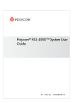
Chapter 1- System Overview
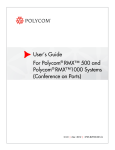
LAN
PC
RMX
1000
RMX1000
HDX
RMX 1000
Web Client
IP Phone
Figure 1-1 Multipoint Video Conferencing Using a Polycom RMX 1000
1-2
Polycom RMX 1000 User Guide
RMX 1000 Main Features
Video Display
Dynamic Continuous Presence
The dynamic Continuous Presence capability of the RMX 1000 system
ensures viewing flexibility by offering multiple viewing points and window
layouts for video conferencing. The Continuous Presence mode offers 24
different onscreen layouts to accommodate different numbers of participants
and conference settings.
High Definition
High Definition (HD) refers to high-quality picture resolution. An
HD-compliant endpoint can connect to a conference at a resolution of
1280x720 (720p) and a bit rate of 1024 kbp ~2 Mb.
Multiple Switching Modes
If the number of participants in a conference is higher than the number of
onscreen spaces in the selected layout, the RMX 1000 system supports
switching between video participants in one of these modes:
•
Voice activation (loudest sites are included in the layout)
•
Administrator-specified (one or more participants configured for display
in a selected video window)
•
Lecture Mode – The lecturer is viewed in full screen by all conference
participants, while the audience is rotated through the lecturer’s view in
a “time-switched” mode.
H.239
An H. 239 compliant endpoint can simultaneously send and receive two
channels of conference video streams: dynamic conference video and PC
screen content. This mode of content sharing is used for many functions, such
as training or reporting.
Media Encryption
The system has an optional AES 128-bit media encryption mode, so the
conferencing connection is more secure.
LPR
LPR (Lost Packet Recovery) is a Polycom algorithm designed to protect IP
video calls from the impact of network packet loss. LPR offers five key
benefits:
•
Allows users to conduct high quality video calls over loss-prone IP
networks (DSL, cable, satellite, high contention LANs / WANs, etc.)
without suffering the effects of packet loss.
•
Protects video calls from short-term network issues by temporarily
adjusting the bit rate of the call in progress.
•
Reduces the jitter buffer and associated delay.
1-1
Chapter 1- System Overview
•
Allows an organization to use all available bandwidth for its video calls.
•
Protects all elements of the videoconference call; voice, video, and
content.
IVR-Enabled Conferencing
The Interactive Voice Response (IVR) function lets participants perform
various operations during ongoing conferences according to voice prompts.
The participants use their endpoints’ keypads and remote control to interact
with the conference’s menu-driven scripts using Far-End Camera Control
(FECC) and DTMF codes.
Recording Link
The RMX 1000 system supports recording links similar to other Polycom
MCUs. This recording link can work with the Polycom RSS 2000 to record the
content of an RMX 1000 conference.
Conferencing Capabilities and Options
On Demand Conferencing
The following options are available when setting up conferences:
•
Instant Conference – Convene an instant one-time-only conference. The
conference is deleted from the MCU immediately after its completion.
•
Meeting Room – Meeting rooms are stored in the MCU memory, without
occupying any MCU resources until used. They can be activated
anytime.
•
Reserve a Conference (using SE 200, or internally with optional with
keycode) – The reserved conference is stored on the SE 200 (or RMX 1000,
if using internal scheduling) and occupies resources only for its specified
timeframe. The system automatically initiates and terminates the
conference according to the reservation start and end times.
Connection Methods
•
Dial-out: automatically connect pre-defined participants (automatic line
rate detection)
•
Dial-in:
― Inbound calling by pre-defined participants
― Inbound calling by undefined participants
Conference Management and Monitoring Features
The Polycom RMX 1000 Web Client provides capabilities for management
and monitoring of participants and conferences as follows:
1-2
•
Lecture Mode in Continuous Presence conferences
•
Far End Camera Control (FECC/LSD) in video conferences
•
Automatic termination of empty (no participant) conferences
•
Control of listening and broadcasting audio volume for individual
Polycom RMX 1000 User Guide
participants
•
Conference control via DTMF codes from participant’s endpoint or
telephone
•
Multimedia encryption
•
Real-time display of all conferences and participants
•
Real-time monitoring of each participant’s connection status and
properties
•
Easily accessible Call Detail Records (CDR) for administrator
•
Active display of all system resources
User Interfaces
Web Interface
The system provides a user-friendly Web-based operations interface. To
conveniently and easily manage and monitor conferences, or maintain the
device, the user only needs to access the Web client program of the RMX 1000
system by using the IE browser at the PC. The Web interface is designed for
both administrator and operator level users.
Personal Conference Manager (PCM)
The Personal Conference Manager (PCM) is a menu-based onscreen interface
viewed on a participant’s endpoint. The user can perform common
conference operations using the endpoint’s remote control and onscreen
operation menus. The interface is designed for end users.
Full Integration with SE 200
The RMX 1000 system can be completely integrated with the Polycom
ReadiManager SE 200 for centrally-managed scheduling. The SE 200 can
manage the RMX 1000 as follows:
•
Viewing details of the RMX 1000 system
•
Modifying conference profiles and scheduling conferences
•
Monitoring ongoing conferences
•
Managing the ongoing conference and participants, e.g., extending the
conference time, terminating the conference, adding/deleting a
participant, and sending notification E-mails to a participant
1-3
2
First Time Installation and
Configuration
Follow the procedure below to implement First Time Installation and
Configuration of the RMX 1000 system:
1
Hardware Installation and Setup
2
Configuration Preparations
― Get the information needed for network configuration.
― Get the product activation key.
3
First Time Configuration
― Connect a PC to the RMX 1000.
― Log in to the Web interface.
― Modify the default IP address.
― Configure other network options.
Hardware Installation and Setup
Install the hardware and connect lines as described below:
1
Put the RMX 1000 product on a stable surface at the installation site.
2
Carefully take the RMX 1000 device out of the package. You can install
the device in the rack or position it on an even surface.
3
― Mount the RMX 1000 in the rack: Install rack brackets, supplied by
the rack manufacturer, in the rack. Mount the RMX 1000 on top of the
rack brackets. Fasten the RMX 1000 to the rack with screws.
― Put the RMX 1000 on a safe, even, and clean surface.
Connect cables on the back panel of the RMX 1000:
― Power Cable: Firmly insert the plug into the power socket to prevent
poor contact.
― LAN Cable: Connect to the LAN1 port of the RMX 1000.
Configuration Preparations
Obtaining Network Information
Before the first time configuration, obtain the following information from the
network administrator. This helps you to configure the RMX 1000 in your
local network:
2-1
Chapter 2- First Time Installation and Configuration
•
The IP address, subnet mask, and default gateway IP address of the RMX
1000 LAN port
•
(Optional) Gatekeeper address, and the H.323 prefix and E.164 number
to be assigned to the RMX 1000
Obtaining Product Activation Key
Before using the RMX 1000, you need to register and activate the device.
Follow the procedure below to obtain the product activation key. When you
power on and log in to the RMX 1000 for the first time, the system displays
the Product Activation dialog box, requesting you to enter a Product
Activation Key.
1
Enter http://portal.polycom.com in the address bar of the browser to
access the login page of the Polycom resource center.
2
In the login box, enter your Email address and password, and then click
Sign In. If you are a new user, click the Register for an Account link for
registration.
3
Click Service & Support in the upper navigation bar on the interface. On
the Service & Support page, click Product Activation in the left navigation
bar.
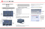
Figure 2-1 Service & Support Page
2-2
Polycom RMX 1000 User Guide
4
Enter the Activate Your Product page. Enter the License Number and
Serial Number of the product in the Single License Number pane, and
then click the Generate button. You can find the license number and
serial number of the product from the document provided with the RMX
1000. Record the activation key displayed in the Key Code field.
Figure 2-2 Activation Key Generating Page
First Time Configuration
Connecting PC to RMX 1000
1
Connect your PC to the LAN1 port (the LAN1 port is enabled by default)
of the RMX 1000 with a cross-over network cable, or connect your PC
and RMX 1000 to the same switch in the LAN. Turn on the power switch
at the RMX 1000.
2
Configure the IP address for your PC, which is in the same network
segment as the IP address of the RMX 1000.
The default IP address of the RMX 1000 before delivery is:
― IP address of the LAN1 port - 192.168.1.254
― Subnet mask - 255.255.255.0
― Default gateway IP address - 192.168.1.1
You can also view the current address information of the product using
the RMX 1000 Discover tool provided with the device.
Run the RMX 1000Discover.exe file in the CD provided with the product.
Click the Discover button to display the current address information of
the device.
2-1
Chapter 2- First Time Installation and Configuration
Figure 2-3 RMX 1000 Discover Tool Interface
Logging in to Web UI
1
Run the Web browser on the PC. Enter http://<RMX 1000 IP address> in
the address bar, and then press Enter.
2
(Optional) Select a language for the Web interface from the drop-down
menu. If the browser or OS of your PC does not support the selected
language, the content is displayed in English.
3
On the Welcome interface, enter the default User Name (POLYCOM) and
Password (POLYCOM). Click the Login button to enter the Web
configuration interface.
Figure 2-4 Logging in to the RMX 1000 Web Interface
4
2-2
The Product Activation dialog box is displayed. Fill in the activation key
obtained in Obtaining Product Activation Key in the Activation Key box,
and then click the Save button. Click the Close button.
Polycom RMX 1000 User Guide
Figure 2-5 Product Activation Page
Modifying the Default IP Address
After accessing the RMX 1000 Web configuration interface, you can modify
the default IP address for the device based on the settings of your local
network.
1
Click the IP Setting configuration item in the RMX Management pane.
2
In the IP Setting configuration pane, right-click, and select LAN1 ->
Properties.
3
In the LAN1 Settings dialog box, set the IP address obtained from the
network administrator, and configure the device for use on your local
network.
Figure 2-6 Modifying the IP Address
Table 2-1 LAN Port Setting Parameters
Parameter
Description
2-3
Chapter 2- First Time Installation and Configuration
Parameter
Description
Use LAN1
Enables/disables the network port
DHCP
If the user network is configured with a Dynamic Host
Configuration Protocol (DHCP) server, select this option
to automatically obtain the IP address.
Deselect this option to use a static IP address, in which
case you need to configure the next three options.
IP Address
Set the IP address for this network port
Subnet Mask
Set the subnet mask for this network port
Gateway
Set the gateway address for this network port. If the Set
as Default option is selected, the device packet will be
forwarded through this gateway by default when there is
no matched static route. In this case, a default route is
displayed in the list of the Advanced Setting -> Router
page. For details, refer to the Routers section.
NAT
The Network Address Translation (NAT) function enables
you to translate a private network IP address into a public
network IP address before transmission. To enable NAT,
select this box and then type the public network IP
address to be displayed to the outside.
Obtain DNS server
address automatically
Used in combination with the DHCP option. When the
DHCP check box is selected, this option allows you to
obtain the DNS server address automatically from a
DHCP server in the network.
Preferred/Alternate
DNS Server
If you did not select the option for automatic DNS address
discovery, you must enter the preferred/alternate DNS
server addresses here for the device to resolve domain
names.
LAN Speed
Sets the speed/duplex modes for LAN ports. Supported
speed/duplex modes include 10/100M, Full Duplex or Half
Duplex, and the 1000M Network mode. You can also
select Auto to use Auto-Negotiation with the switch port.
Note: Contact the network administrator before setting
LAN Speed, to ensure that the switch configuration is
matched with the MCU port.
Configuring Other Network Options (Optional)
If necessary, you can configure other network parameters according to the
following procedure:
2-4
1
Click the Advanced Setting configuration item in the RMX Management
pane.
2
In the Advanced Setting configuration pane, double-click the list item or
right-click and then select Properties.
3
Based on the network requirement, set the routing information in the
following dialog box.
Polycom RMX 1000 User Guide
Figure 2-7 Advanced Setting – Routers Setting
Table 2-2 Routers Setting
Parameter
Description
Router IP Address
Set the IP address for the sending router of packet
transmission.
Remote IP Address
Set the target network address for packet transmission
Subnet Mask
Set the subnet mask for the target network
4
Click the Gatekeeper tab and set the required gatekeeper information.
Figure 2-8 Advanced Setting – Gatekeeper Setting
Table 2-3 Gatekeeper Setting
Parameter
Description
2-5
Chapter 2- First Time Installation and Configuration
Parameter
Description
Register to Gatekeeper
Set whether or not to register with the gatekeeper. You
must check this option to set the following parameters.
Primary (Alternate)
Gatekeeper
Indicates whether or not the device is registered with the
primary (or alternate) gatekeeper.
Gatekeeper IP address
Set the IP address for the primary (or alternate)
gatekeeper.
Gatekeeper Port
The port number for the primary (or alternate) gatekeeper.
System Prefix/E164.
Set the E.164 number for the system.
System H.323 Alias
Set the H.323 alias for the system.
5
Click the OK button to complete the configuration.
For more network service configuration information, refer to Advanced
Setting.
2-6
3
Basic Operation
This chapter introduces the Web UI components of the RMX 1000 and
common operations, and how to start a simple conference. The goal of this
chapter is to provide a quick guide on how to start a conference with minimal
effort.
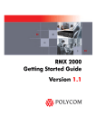
RMX 1000 Screen Components
The Web configuration homepage of the RMX 1000 consists of five panes:
•
Conference List
•
RMX Management
•
List Pane
•
Address Book
•
Status Bar
Conference
List Pane
List Pane
Address
Book
RMX
Management
Pane
Status Bar
Figure 3-1 Layout of the Web Interface
User Rights
You can log in to the Web interface as a conference chairperson, an operator,
or an administrator.
3-1
Chapter 3- Basic Operation
RMX 1000 can support a maximum of 20 users simultaneously connected to Web UI.
The table below shows the operation abilities of users at different levels when
accessing the Web interface of the RMX 1000.
Table 3-1 List of User Rights
View
Chairperson
Operator
Administrator
Conference List
√
√
√
List Pane
√
√
√
Address Book
√
√
√
Status Bar
√
√
RMX Management
√
√
Conference Alert
√
√
Conference Status
√
√
Configuration Interface
√
√
System Operations
Chairperson
Operator
Administrator
Start Conference
√
√
√
Monitor Conference
√
√
√
Monitor Participant
√
√
√
√
√
Solve Basic Problems
Modify Device
Configuration
√
The administrator has all operation rights to the Web interface. Unless otherwise
specified, this guide describes the interface operations of an administrator.
Pane Layout
Conference List
The Conferences list pane shows all the conferences running on the current
device and their relevant information, including status, ID, start time and end
time. Here you can create, delete, and lock conferences, as well as view
conference details. The title bar of the pane indicates the number of the
3-2
Polycom RMX 1000 User Guide
ongoing conferences.
Figure 3-2 Conference List Pane
If you log in as the conference chairperson, the pane only shows the
conferences with no chairperson password. To view the conferences for
which a chairperson password is set, enter the password in the Chairperson
Password box.
RMX Management
The RMX Management pane lists the menu options for conference
configuration, in addition to device maintenance and management. Only
users at administrator or operator levels can configure the menu options.
After an item is selected in the RMX Management pane, the corresponding
configuration items will be displayed in the List pane.
List Pane
The List Pane displays a list of the participants of the ongoing conference by
default. When you click a menu item in the RMX Management pane, the List
Pane displays the related parameter list. You can view all the property
parameters and make specific configurations. The panel title varies with the
selected option.
Status Bar
Located at the bottom of the Web interface, the status bar shows the system
alert information, H.323 link status, resources usage and MCU status.
•
System Alerts
The indication bar shows problems with the system. If there are problems
with the system, this indication bar flashes in red until all the problems
are solved.
Click System Alerts on the left part of the Status Bar to display the system
alert pane. For more information about System Alerts, see System Alerts.
•
H. 323 Link Status
This indication bar shows in real time the endpoints connected with the
system and relevant information. When an H.323 endpoint is connected
to the device, Connected H. 323 Link on the status bar is highlighted in red.
Click this control to open the H.323 link status pane. For more information
about H.323 links, see H.323 Link.
3-3
Chapter 3- Basic Operation
•
Resources Usage
This indication bar shows the number of Resources used in the system
and Resources available in the system. For example,
indicates that 40 resources are available
and 4 of them are in use. Click Resources Usage to view details about
Resources usage, as shown below.
Figure 3-3 Resources Usage Information
•
MCU State
The following explains the information displayed in the MCU State area:
―
- The MCU is functioning normally.
―
- The MCU has a MINOR problem but keeps
working.
―
- The MCU has a MAJOR problem. MCU
behavior could be affected and attention is required.
Address Book
The Address Book shows the participant information set on the RMX 1000. It
enables users to easily add participants to the conference. Here the user can
add and delete participants or set participant groups. For more information
about the address book, see Address Book.
Common Operations
List Sorting
All the list items on the Web interface can be sorted by parameter properties.
Click the desired column header in the list. When a small triangle ( )
appears, you can sort the list in ascending or descending order. After a list is
sorted by a column header in ascending (or descending) order, you can click
the column header again to sort it in opposite order.
3-4
Polycom RMX 1000 User Guide
Figure 3-4 List Sorting
Right-click Shortcut Menu
The Web interface provides right-click shortcut menus for common
operations such as viewing detailed parameters, creating/deleting items, etc.
Alternatively, you can perform these operations by double-clicking the
corresponding list items or by using the corresponding buttons on the toolbar
of the pane.
Pane Sizing
Move the mouse pointer to the border of the pane; when the pointer turns
into an arrow, drag to size the pane while holding down the left mouse
button.
Confirm/Cancel
To confirm your settings on the parameter configuration interface, click the OK
button in the lower part of the interface. To abort your settings, click the
Cancel button.
Starting a Conference
There are several ways to start a conference with the RMX 1000:
•
Click the New Conference button in the Conferences pane.
•
Directly enter the dialing number, including a new conference ID,
through the remote control.
•
Dial into a meeting room. A Meeting Room is a conference that is saved
in the MCU, without occupying any resources. It remains in passive
mode until it is activated by the first participant. For more information
about Meeting Rooms, see Meeting Room.
•
Reserve a conference (optional): The reserved conference is stored at the
MCU and reserves system resources for the call’s specified time. The
3-5
Chapter 3- Basic Operation
system automatically convenes the conference according to the
reservation time. For more information about conference reservation, see
Reservation.
•
Dial into the PCM (personal control manager) lobby to create a
conference. For more information about creating a conference via PCM,
see Creating a Conference.
This part describes how to create a conference instantly through the
Conferences pane and remote control. An instant conference can be established
only when the required system resources are available. The conference is
deleted right after its completion to maximize system resources.
The RMX 1000 can support a maximum of 32 ongoing conferences.
Starting a Conference from the Conferences Pane
Click
in the Conferences pane to display the New Conference page.
Figure 3-5 New Conference Page
The New Conference page displays the default conference name, duration,
profile of conference parameters, and the conference ID automatically
allocated by the system. These options are configurable, but none of these
settings need to be modified to start a conference.
The conference chairperson or organizer should inform other participants of
the conference ID used for the conference, so that they can dial in.
If necessary, set the basic parameters for the meeting and add participants or
relevant supplementary information as desired. For more information, see
Creating a Meeting Room.
After completing the setup, click OK. After that, the conference list shows that
the new conference is running. If no participant is specified for the conference,
the status is displayed as
conference.
3-6
, until a participant dials in to the
Polycom RMX 1000 User Guide
Figure 3-6 Running an Instant Conference
Starting a Conference Using the Remote Control
To create a new conference directly by the remote control of an endpoint,
enter the dialing number as described in the table below on the remote
control.
Table 3-2 Dialing number for Creating a conference
Scenario
Dialing Number
Create a conference
which has no
password
RMX 1000 is registered to GK:
[RMX 1000 E.164 Prefix][Conference ID]
RMX 1000 isn’t registered to GK:
[RMX 1000 IP Address]##[Conference ID]
Create a conference
which has one
password only
RMX 1000 is registered to GK:
[RMX 1000 E.164 Prefix][Conference ID]##[Password]
RMX 1000 isn’t registered to GK:
[RMX 1000 IP Address]##[Conference ID]##[Password]
Note: If only one password is entered, it will be defined as a
chairperson password. In this case, there won’t be a
conference password and the user will receive the
chairperson abilities.
Create a conference
which has both
conference and
chairperson password
RMX 1000 is registered to GK:
[RMX 1000 E.164 Prefix][Conference ID]##[Conference
Password]##[Chair Person password]
RMX 1000 isn’t registered to GK:
[RMX 1000 IP Address]##[Conference ID]##[Conference
Password]##[Chair Person password]
Note: The conference password and chairperson password
must be different. If the user enters the same password for
both, the call will be rejected.
The conference ID the user enters for creating a new conference must be unique different from existing conference IDs.
3-7
Chapter 3- Basic Operation
For example, if the RMX 1000 is registered to GK and gets 925 as an E.164
prefix:
To create a conference using conference ID 1001, dial 9251001;
To create a conference using conference ID 1001 and chairperson password
2222, dial 9251001##2222;
To create a conference using conference ID 1001, with conference password
1111 and chairperson password 2222, dial 9251001##1111##2222.
Connecting to a Conference – Dialing Methods
To connect an endpoint to the ongoing conference or meeting room, there are
two dialing methods:
•
Dial into the PCM lobby to enter an existing conference. For more
information about connecting to a conference via PCM lobby, see
Entering an Existing Conference.
•
Directly dial into the conference using the remote control. In this way,
the user must obtain the conference ID and password (if the conference
password or chairperson password is set) first. For more information, see
the following sections.
Dial-in – RMX 1000 Registered to GK
If both the calling endpoint and RMX 1000 are registered to the same GK, see
the below table for the proper number to be dialed by the endpoint.
Table 3-3 Dialing Number – RMX 1000 Registered to GK
Dialing Scenario
Dialing Number
No password is set
for the conference
[RMX 1000 E.164 prefix (or H.323 alias)][Conference ID]
Passwords are set
for the conference
[RMX 1000 E.164 prefix (or H.323 alias)][Conference
ID]##[Password]
Note: If the password entered is the conference password, the
user will be joining as a regular participant. If the password is
the chairperson password, the user will be joining as a
chairperson.
Alternatively:
[RMX 1000 E.164 prefix (or H.323 alias)][Conference
ID]##[Conference Password]##[Chairperson password]
For example:
RMX 1000 E.164 alias: 925
Conference ID: 1001
Conference name: Maple Room
3-8
Polycom RMX 1000 User Guide
If no password is set for the conference, the call-in number to be used by
participants is: 9251001.
If passwords are set for the conference, for example, if the conference
password is 1111 and chairperson password is 2222, a regular participant
would dial 9251001##1111, while a chairperson would dial 9251001##2222 or
9251001##1111##2222.
Dial-in – RMX 1000 Not Registered to GK
If no gatekeeper is configured for the network service, see the below table for
the proper number to be dialed by the endpoint.
Table 3-4 Dialing Number – RMX 1000 not Registered to GK
Dialing Scenario
Dialing Number
No password is set
for conference
[RMX 1000 IP Address] ## [Conference ID]
Passwords are set
for the conference
[RMX 1000 IP Address] ## [Conference ID]##[Password]
Note: If the password is the conference password, the user will
be joining as a regular participant. If the password is the
chairperson password, the user will be joining as chairperson.
Alternatively:
[RMX 1000 IP Address] ## [Conference ID]##[Conference
Password]##[Chairperson password]
For example:
RMX 1000 IP address: 172.22.30.40
Conference ID: 1001
Thus, the call-in number to be used by participants is: 172.22.30.40##1001.
If the passwords are set for the conference, for example, if the conference
password is 1111 and chairperson password is 2222, a regular participant
would dial 172.22.30.40##1001##1111, while a chairperson would dial
172.22.30.40##1001##2222 or 172.22.30.40##1001##1111##2222.
If the Conference ID the user entered does not exist, the RMX 1000 will create a new
conference with this conference ID. For more information, see Starting a Conference
Using the Remote Control.
3-9
4
Conference Profiles
A conference profile is used to pre-define the basic parameters for conference
scheduling, such as the bandwidth, encryption, and video quality. All
conferences will be created on the basis of conference profiles. By saving
conference profiles on the RMX 1000, users can conveniently and rapidly
schedule new conferences without performing repeated configurations.
The system is shipped with five default conference profiles as shown in the
table below.
Table 4-1 Default Conference Profiles
Profile Name
Parameters
Default_768_CIF_H264Content
(Default Profile)
With H264 Content
768_4CIF_H264Content
4CIF, H264 with H264 Content
384_CIF_H264Content
384 CIF with H264 Content
384_CIF_H263Content
384 CIF with H263 Content
2M_720p_H264Content
(Appears only if the H.264 720p
option is activated.)
2M 720p with H264 Content
The following parameters generally decide the video conference quality:
•
Bit Rate - The transmission rate of the audio and video streams. The
higher this value is, the better the displayed video quality.
•
Audio Algorithm - The audio compression algorithm determines the
audio quality of the video conference.
•
Video Protocol, Video Format, and Frame Rate – These parameters
define the quality of the video picture. When an endpoint is connected to
the conference, it will select a video capability based on the video
parameters set for the conference. For example, if the video protocol for
the conference is H.264, an endpoint that supports the H.264 protocol
will select H.264 for video-coding when it connects to this conference.
The following features are commonly used to define a conference:
•
H. 239 Dual-stream – An H. 239 compliant endpoint can simultaneously
send and receive two channels of conference video streams: dynamic
conference video and PC screen content. The endpoints participating in
the conference must use the same bit rate, protocol, and resolution in
order to view the PC contents. Endpoints that do not support H.239 can
4-1
Chapter 4 - Conference Profiles
be connected to the conference but cannot view the PC content.
•
Lecture Mode – All the participants in this mode will see the lecturer in
full-screen, and the lecturer will see all the participants in the selected
screen layout.
•
Encryption – The system provides AES 128-based multimedia encryption
to strengthen conference security.
To set a conference profile, click Conference Profile in the RMX Management
pane. The list pane shows the profiles saved on the current device and their
summaries.
Figure 4-2 Conference Profile List
Defining a Profile
To create a conference profile, click
in the Conference Profile list pane, or
right-click in the blank area in the pane, and then click New Profile. The New
Profile interface appears, as shown below. The RMX 1000 fills in default
settings. For basic operations, you only need to define the display name of
the profile. If necessary, you can set additional conference parameters, such
as video quality, video layout, conference skin, recording parameters, etc.
4-2
Polycom RMX 1000 User Guide
Figure 4-3 Defining a Profile
General Settings
On the New Profile page, click the General tab to display the interface for
configuring general parameters, as shown in the figure above. The table
below explains the detailed meanings of profile parameters.
Table 4-2 General Parameters
Parameter
Description
Display Name
Enter a unique name to identify this profile.
Note: This is the only mandatory parameter when you
create a new profile.
Line Rate
Select the conference line rate. Line rate indicates the rate
that integrates video, audio, and data contents. The default
value is 768Kbps.
Encryption
Set whether to enable the AES encryption function for this
profile.
Note:
If any conference uses the profile with AES encryption
enabled, an endpoint that does not support the
encryption capability cannot join in the conference
through the PCM (Personal Conference Manager).
Endpoints can access the conference only by directly
calling the RMX 1000 E.164 + conference ID.
The RMX 1000 version for some geographic areas may
not allow for the encryption option.
Auto Mute
If this check box is selected, after an endpoint dials into the
conference, the RMX 1000 will automatically mute it.
Auto Terminate
If this check box is selected, the system will automatically
terminate the conference when any of the following
conditions is satisfied:
Before First Join - No participant joins in within the set
time after the conference starts. The default idle time is
10 minutes.
After Last Quit - All participants have quit the conference,
and the conference is idle for the predefined time. The
default idle time is 1 minute.
This check box is selected by default.
Minimum ports to be
Set the minimum number of conference participants.
4-3
Chapter 4 - Conference Profiles
Parameter
Description
reserved
Disable Personal
Conference
Management(PCM)for
Regular User
If this check box is selected, the user who enters the
conference as a regular participant cannot display the
PCM menu to control the conference. For related
information, refer to Conference Control for Regular
Participants.
Video Quality
To set the video quality parameters for the conference, click the Video
Quality tab to enter the following page.
Figure 4-4 Video Quality Setup Page
Set the video quality of the conference screen. You can select one of the
following five modes:
Table 4-3 Video Quality Parameters – First Video Definition
4-4
Video Definition
Description
Up to H.264, CIF/SIF
It is used for the screen display of ordinary quality. The
conference video can be best coded/decoded with the
H.264 protocol and displayed with the CIF/SIF resolution,
requesting the lowest bandwidth requirement and
occupying the minimum system resources. Each endpoint
in the conference occupies only 1 H.323 connection
resource.
Up to H.263, 4CIF/4SIF,
15FPS
It is used for the screen display of high quality. The
conference video is coded/decoded with the H.263
protocol and displayed with the 4CIF/4SIF resolution and
15FPS frequency, requesting a higher bandwidth. Each
endpoint in the conference occupies only 1 H.323
connection resource.
Up to H.264, 4CIF/4SIF
It is used for the screen display of higher quality. The
conference video is coded/decoded with the H.264
protocol and displayed with the 4CIF/4SIF resolution. The
endpoint must support the H.264 protocol and the
bandwidth cannot be lower than 384Kbps. Each endpoint
in the conference occupies 2 H.323 connection resources.
(Optional with keycode)
Up to H.264, 720P
(Common Layout)
The conference video can be best coded/decoded with the
H.264 protocol and displayed with 1280x720 (720p) HD
resolution, occupying more system resources. The
Polycom RMX 1000 User Guide
Video Definition
Description
conference under this mode has the following restrictions:
The endpoint must support the H.264 protocol and 720p
resolution, and the bandwidth cannot be lower than
1Mbps. Otherwise, the conference video will be
degraded to the 4CIF/CIF resolution display or H.263
coding depending on the capability of the endpoint that
joins in the conference.
It supports only the Same Layout video mode, and the
same video layout is displayed for all the conference
sites. For more information about the Same Layout
mode, refer to Video Settings.
The system can support convening a maximum of 5
720p conferences at the same time.
When a 720p conference is ongoing, the screen of the
participant’s endpoint displays only the conference
video. The PCM menu is unavailable. For more
information about PCM, refer to Personal Conference
Manager (PCM).
Note: “Up to H.264, 720P” is an optional function of the
RMX 1000 and will not be available until a license is
purchased. If the license for this function is not activated,
the device does not display the related options. To obtain
this function, please contact your supplier.
High Definition Video
Switching Highest
Common
When this option is selected, the conference video is
displayed at the HD resolution (720p). The RMX 1000
forwards rather than codes/decodes the data sent from the
HD endpoint. Each endpoint in this conference occupies
only one H.323 connection resource. The conference
under this mode has the following restrictions:
The endpoint must support the H.264 protocol and 720p
resolution, and the bandwidth cannot be lower than
1Mbps. Otherwise, the conference video will be
degraded to the 4CIF/CIF resolution display or H.263
coding depending on the capability of the endpoint that
joins in the conference.
The system supports only the Lecture Mode video
mode. The conference lecturer is displayed on the
screens of the other conference sites. The endpoint of
the lecturer can be switched to display each conference
site. For more information about the Lecture Mode, refer
to Video Settings.
The system supports only one conference video layout
( ).
The system does not support the setting of conference
skin. For more information on conference skins, refer to
Conference Skin.
Set the video parameter for the second channel of PC video when dual
streams are sent.
Table 4-4 Video Quality Parameters – Second Video Definition
Video Parameter
Description
Content Setting
Set the video protocol used for the dual-stream video. You
can select the H.264 or H.263 coding/decoding algorithm
based on the endpoint capability and network bandwidth.
4-5
Chapter 4 - Conference Profiles
Video Parameter
Description
When None is selected, it indicates dual streams are not
enabled.
Note: If this setting is H.264, when an endpoint that only
supports H.263 protocol joins in the conference, an H.264
endpoint that originally sent dual streams will terminate
sending dual streams and resend them using the H.263
protocol.
H.239 Setting
The H.239 protocol is used to send dual streams. You can
select three kinds of video quality as needed:
Graphics: for standard video display
Hi-res Graphics: for high-quality video detail display.
Broader bandwidth is required.
Live Video: for full-motion of dynamic video display. The
broadest bandwidth is required.
The RMX 1000 supports a maximum of 20 H.323 video connections and 20 H.323
audio connections. Therefore, the number of endpoint connections supported by the
device in the actual conference depends on the video definition.
Video Settings
To set the conference video layout, click the Video Settings tab on the New
Profile interface.
Figure 4-5 Video Settings
In the Video Mode drop-down menu, you can set three video layout modes:
•
4-6
Lecture Mode: If this option is selected, when the lecturer speaks, all the
participants’ endpoints will display the lecturer in full screen, and the
lecturer’s endpoint will display other participants according to the layout
Polycom RMX 1000 User Guide
set here.
•
Same Layout: If this option is selected, all participants’ endpoints will
display the same video according to the layout set here, and no video
layout can be customized. This setting will allow sites to see their own
loopback image.
•
Conference Layout: If this option is selected, the video layout can be
customized on each video conference endpoint. After this option is
selected, the operator can set participant properties through the Web
interface (for more information, see Setting Conference Layout for
Participant’s Endpoint) and the participant can choose a personal layout
by operating the endpoint via remote control (for more information, see
Click & View.)
The video setup interface shows the layout number and corresponding video
layout modes. For the default layout, see the table below.
Table 4-5 Video Layout Rules (Default)
Layout Number
Layout
0-2
3
4-5
6-7
8+
The user can also customize a different layout mode as needed in this way:
click the corresponding layout number, and then select the desired layout in
the expanded pane, as shown below.
Figure 4-6 Customizing Video Layout
In an actual conference, when the number of participants is greater than the
4-7
Chapter 4 - Conference Profiles
layout number set here, the operator can specify a window to display the
participants by turns. For details, please refer to Changing Conference Layout.
Auto Scan Interval is used to set the time interval for the system to
automatically switch to the next participant. The default value is 20 seconds.
Conference Skin
To set the background and border color of the video to be displayed on the
endpoint, click the Skins tab on the New Profile interface. The tab provides
four skins for your selection.
Figure 4-7 Meeting Room Parameter Setup Interface
To set the required skin, select the check box, and then click the OK button.
The user can also set the conference skin during an ongoing conference. For related
information, see Changing Conference Skin.
If the video mode is set to High Definition Video Switching Highest Common in Video
Quality, the conference skin cannot be set through this interface.
Conference Recording
The RMX 1000 can work with the Polycom RSS 2000 recording server to
record conferences. Click the Recording tab on the New Profile interface to
enter the related information and set the recording parameters.
4-8
Polycom RMX 1000 User Guide
Figure 4-8 Recording Parameter Setup Interface
The table below explains the configuration parameters.
Table 4-6 Conference Recording Configuration
Parameter
Description
Enable Recording
If an RSS 2000 is available on your network, you can select
this option to enable the recording function.
Start
Select the start time of the conference recording:
Immediately – The recording automatically starts
immediately after the first participant joins the conference.
Upon Request – The operator or chairperson starts the
recording manually. After this option is selected, the
recording can be manually started through the Web interface
or DTMF function. For more information, see Recording
Control.
Audio Only
If this option is selected, only the conference audio will be
recorded.
•
•
The recording parameters can be set here only after the IP address of the RSS
2000 is configured on the Recording Link interface. For how to set Recording Link,
see Recording Link.
The recording link occupies one conference resource.
Modifying a Profile
To modify a saved profile, right-click it in the Profile list, and then click
Profile Properties to modify its properties. For explanation of the
configuration parameters, see Defining a Profile.
Deleting a Profile
To delete a profile, select it in the Profile list, and then click
right-click the desired profile and then click Delete Profile.
; Alternatively,
A profile in use cannot be modified or deleted.
Setting a Default Profile
After a default profile is set, endpoints will use it when creating a conference
from the lobby. In addition, when users create a meeting room, reserve a
conference, or convene an instant conference via the Web interface, the
4-9
Chapter 4 - Conference Profiles
default profile will be used unless otherwise specified.
To set a default profile, right-click the desired profile in the Profile list, and
then click Set as Default. After that, the icon of the profile becomes
.
A profile with the AES encryption function enabled cannot be set to a default profile.
4-10
5
Recording Link
The RMX 1000 supports the recording link function. It can work with the RSS
2000 to record conference content. After the recording setup is completed,
when the conference starts, the RMX 1000 will first call the participants in the
participant list, and then call the configured RSS 2000 to record the
conference. The recording link is displayed in the List pane as a regular
participant, thereby enabling users to view and control the recording status
easily.
To record a conference running on the RMX 1000 through the RSS 2000, make
sure to verify the following:
•
The profile used for the conference has enabled the recording function.
For details, refer to Conference Recording.
•
The information of the RSS 2000 is configured on the recording
connection. For more information, see Recording Setup below.
Recording Setup
In the RMX Management pane, click Recording Link. The Recording Link
interface appears in the list pane located on the right side. Here you can view
the IP address and alias configured for the RSS 2000.
Figure 5-1 Recording Link
5-1
Chapter 5 - Recording Link
Right-click the RSS IP address and then click Properties to display the General
tab of the Recording Link page.
General Settings
Figure 5-2 Recording Link–General
The table below explains the detailed meanings of these parameters.
Table 5-1 Recording Link–General
Parameter
Description
RSS 2000 IP
Address
Enter the IP address of the RSS 2000 to be connected. This
item is optional if an alias is set in the Alias check box below.
RSS 2000 Alias
Enter the E.164 number or H.323 alias of the RSS 2000 in
accordance with the selected alias type. This item is optional if
the IP address of the RSS 2000 is set.
Alias Type
Set the alias type of the RSS 2000: H.323 or E.164.
DTMF Code Setting
To set the recording control operations and rights for use by connected
endpoints, click the DTMF Codes tab.
Figure 5-3 Recording Link-DTMF Codes
The table below explains the detailed meanings of these parameters.
5-2
Polycom RMX 1000 User Guide
Table 5-2 Parameter Description for Recording Link – DTMF Codes
Parameter
Description
Name
Name of the recording operation
DTMF Code
Set the remote control key combination used to perform the
operation. The default numbers can be customized. For
example, the default DTMF code for the Start Recording
command is *2, you can press the keys *2 to start conference
recording.
Note: Before using the DTMF command, enable the DTMF
function of the endpoint according to that endpoint’s
configurations.
Permissions
Set the rights of using DTMF codes. Chairperson indicates that
the DTMF is available to the conference chairperson only;
Everyone indicates that the DTMF is available to all
participants.
Recording Control
When a conference is going on, you can view and control the status of the
configured recording link. In the Conferences list pane, select the desired
conference. Then the list pane located on the right side shows the defined
participants and connected participants, among which the recording link is
indicated by the
icon.
Figure 5-4 Recording Control
When a conference is going on, you can perform the following recording
control operations through the recording buttons in the list pane or the
right-click shortcut menu.
•
Start recording -
•
Pause recording -
5-3
Chapter 5 - Recording Link
•
Stop recording For more information about the recording control operations of the RSS 2000, see
RSS 2000 User Guide.
5-4
6
Meeting Rooms
A Meeting Room is a conference saved on the MCU in passive mode, without
using any system resources. A Meeting Room is automatically activated
when the first participant dials into it. Once activated, a Meeting Room
functions as any ongoing conference. All Meeting Rooms are based on a
Conference Profile. The RMX 1000 can support up to 1000 meeting rooms.
To set a meeting room, click Meeting Room in the RMX Management pane.
The list pane shows the meeting rooms saved on the RMX 1000 and their
summaries, such as the meeting room name, conference ID, conference
duration, conference password, chairperson password, and conference
profile. Here you can create, modify and delete meeting rooms.
Figure 6-1 Meeting Rooms List
Creating a Meeting Room
To create a meeting room, click
in the list pane or right-click in the blank
area of the pane, and then click New Meeting Room. The New Meeting Room General interface is displayed.
6-1
Chapter 6 - Meeting Rooms
General Settings
Figure 6-2 New Meeting Room - General
The table below explains the detailed meanings of these parameters.
Table 6-1 Parameter Description for New Meeting Room – General
6-2
Parameter
Description
Meeting Room
Name
Set a unique name to identify the meeting room. When a
meeting room is created, the system will automatically
generate a unique name for it.
Profile
Select the profile to be used for this conference from the
drop-down list. The lower part of this option displays the major
parameter values defined for the profile:
Line Rate: The bandwidth of the conference link;
Minimum ports to be reserved: The minimum number of
conference participants. Automatic indicates that the number
of video participants is determined according to the available
resource of the RMX 1000.
The conference profile defines the basic parameters of
conference scheduling, such as the bandwidth, encryption, and
video quality. For more information on profiles, refer to
Conference Profiles. When a conference is created, the system
selects the default profile of the device by default.
Duration
Specify the conference duration in the range of 0-24 hours. The
input format is H:M and the default value is 2:0.
ID
When a meeting room is created, the system automatically
allocates a conference ID. You can also set a unique
conference ID. To directly dial into the conference, the
participant must know its ID.
Conference
password
Enter the conference password. To connect to this conference,
the participant must enter this password. If this parameter is
empty, it means the conference has no password.
Chairperson
password
Enter the password that identifies the chairperson ID. The
system will authorize more rights to the chairperson. If this
parameter is empty, it means the conference has no
chairperson.
Polycom RMX 1000 User Guide
Parameter
Description
Dial Out Manually
When enabled, the system will not automatically call the
participants defined in the meeting room to join the conference
unless the administrator dials out manually.
Participant setup
You can add the participant information to the invited participant list for the
meeting room. When the meeting room is activated, the system will
automatically call the participants defined in the meeting room to join the
conference. To set the invited participant list, click the Participants tab to
enter the relevant interface, as shown below.
Figure 6-3 New Meeting Room - Participants
You can add participants to the list in the following two modes:
1
Click New to create a participant. The configuration interface is the same
as that for adding a new participant to the address book. For explanation
on the configuration parameters, see Creating a Participant in the Address
Book.
2
Click Add From Address Book to select and add a participant from the
address book. In the address book, select the desired participant, and
then click OK. To select multiple participants at one time, click the
desired participants one by one while pressing down the Ctrl key, or
select adjacent ones while pressing down the Shift key.
To delete a participant from the Participant list, select the desired participant,
and then click Remove.
Other configuration parameters are described in the table below:
Table 6-2 Parameter Description for New Meeting Room – Participants
Parameter
Description
Lecture
After adding participants to the list, you can select a participant
6-3
Chapter 6 - Meeting Rooms
Parameter
Description
from the drop-down list to act as the lecturer. By default, Auto
is selected, meaning that the system uses voice activation to
switch between the layouts, and the participant who speaks
loudest will be selected as the lecturer. When the conference is
running under the Lecture Mode, all participants’ endpoints
display the lecturer in full screen, and the lecturer’s endpoint
can time-switch to display other conference sites in rotation.
For details on Lecture Mode, please refer to Video Settings.
Only participants in
the above
participant list can
dial in
When this option is selected, only the participants defined in
the Participant List can dial into the conference.
Email Notification
If this option is selected, after you click OK, the system will
automatically send an email message to notify each participant
in the Participant List to join the conference. This option can be
enabled only if SMTP is configured in the Advanced Setting.
For more information, see Email.
Other information
To configure other information for the meeting room, click the Information
tab. Here you can configure conference notes, site details, accounting
information, etc.
Figure 6-4 New Meeting Room - Information
Modifying a Meeting Room
To modify a meeting room, double-click the desired meeting room in the
meeting room list; or right-click the meeting room, and then click Meeting
Room Properties. For explanation on the configuration parameters, see
Creating a Meeting Room.
Deleting a Meeting Room
To delete a meeting room, double-click the desired meeting room in the
meeting room list, and then click
or right-click the meeting room, and
then click Delete Meeting Room.
6-4
7
Reservations
Multiple types of conference reservations can be implemented using the RMX
1000. You can reserve a conference for one time or convene routine
conferences on a daily, weekly, or monthly basis as needed. The system
reserves resources for conferences, so the conference can be automatically
started at the preset time. The RMX 1000 can support up to 1000 reservations.
The reservation function is an optional function of the RMX 1000 and will be available
only when the user purchases the license. The device does not display the related
options until the license for this function is activated. To obtain this function, contact
your supplier.
To configure a reservation, click Reservation in the RMX Management pane.
The list pane shows the reservations configured on the device and their
relevant information. Here you can create, modify, and delete reservations.
Figure 7-1 Reservation List
Adding a Reservation
To reserve a conference, click
in the list pane or right-click in the blank
area in the pane, and then click New Reservation. On the configuration
interface that appears, set basic information, participants, reservation time,
and other related information. The procedures for setting the General,
Participants, and Information tabs are the same as those for setting a meeting
7-1
Chapter 7 - Reservations
room. For explanation on the configuration parameters, see Creating a Meeting
Room.
To set the reservation mode and start time of the conference, click the
Schedule tab. From the Schedule Mode drop-down menu, select the desired
reservation mode to reserve a once, daily, weekly, or monthly conference.
Figure 7-2 Setting a Reservation Mode
Reserving a One-Time Conference
A one-time reservation indicates that the reservation is only valid for one
occurrence and will automatically be deleted after the conference ends. To
reserve a one-time conference, select one of the following Schedule modes:
•
Permanent: The reserved conference, after being started, will not be
terminated until it is manually terminated or deleted by a chairperson or
web UI user. This option can be selected if you cannot estimate the
duration of the conference in advance.
•
Once: The reserved conference, after being convened, will terminate at
the specified time.
For either of the above modes, you need to set the Start Time of the reserved
conference. In addition, for the Once mode, you need to set the duration of
the reserved conference.
Figure 7-3 Reservation Setup - Once
7-2
Polycom RMX 1000 User Guide
Table 7-1 Parameter Description for Reservation Setup - Once
Parameter
Description
Start Date
Set the start date of the conference.
Start Time
Set the start time of the conference in the format of H:M.
Duration
Set the duration of the conference in the format of H:M.
Reserving a Daily Conference
To reserve a daily conference, set Schedule Mode to Daily.
Figure 7-4 Reservation Setup - Everyday
The conference will be convened at the specified time every day. In the
specified period, this reservation is also deleted when the last conference is
terminated. The table below explains the configuration parameters.
Table 7-2 Parameter Description for Reservation Setup - Daily
Parameter
Description
Start Time
Set the start time of the conference in the format of H:M.
Duration
Set the duration of the conference in the format of H:M.
Start Date
Set the start date of the recurrence range of the reservation.
End Date
Set the end date of the recurrence range of the reservation.
Reserving a Weekly Conference
To reserve a weekly conference, set Schedule Mode to Weekly.
7-3
Chapter 7 - Reservations
Figure 7-5 Reservation Setup - Weekly
The set conference will be convened at the specified time per week. In the
specified period, this reservation is also deleted when the last conference is
terminated. The table below explains the configuration parameters.
Table 7-3 Parameter Description for Reservation Setup – Weekly
Parameter
Description
Start Time
Set the start time of the conference in the format of H:M.
Duration
Set the duration of the conference in the format of H:M.
Start Date
Set the start date of the recurrence range of the reservation.
End Date
Set the end date of the recurrence range of the reservation.
Sun.~ Sat.
Specify the weekday on which the reserved conference will be
convened. Multiple weekdays can be selected. If you select the
Mon. and Fri. check boxes, the conference will be
automatically started at the specified time on every Monday
and Friday.
Reserving a Monthly Conference
To reserve a monthly conference, set Schedule Mode to Monthly.
Figure 7-6 Reservation Setup - Monthly
7-4
Polycom RMX 1000 User Guide
The conference will be convened at the specified time per month. In the
specified period, this reservation is also deleted when the last conference is
terminated. The table below explains the configuration parameters.
Table 7-4 Parameter Description for Reservation Setup – Monthly
Parameter
Description
Start Time
Set the start time of the conference in the format of H:M.
Duration
Set the duration of the conference in the format of H:M.
Start Date
Set the start date of the recurrence range of the reservation
End Date
Set the end date of the recurrence range of the reservation.
Date
Specify the day of month on which the reserved conference will
be convened. If you enter 1, the conference will be
automatically convened at the specified time on the first day of
every month.
At the specified time, the reserved conference will be convened automatically, the
conference icon will become
, and the properties of the conference can be viewed
but cannot be modified. In addition, the conference list will show that the conference is
ongoing.
Modifying a Reservation
You can modify a reserved conference before it is convened.
To modify a reservation, double-click the desired reservation in the
reservation list, or right-click the reservation, and then click Reservation
Properties. In the configuration interface that appears, modify the parameters.
For explanation on the configuration parameters, see Adding a Reservation.
Deleting a Reservation
You can delete a reserved conference before it is convened.
To modify a reservation, double-click the desired reservation in the
reservation list, and then click
, or right-click the reservation, and then
click Delete Reservation.
7-5
8
Address Book
You can use the address book provided by the RMX 1000 to store participant
information, such as the IP address and network communication protocol of
the participant’s endpoint. The address book enables you to conveniently and
easily add participants to a conference.
The group function of the address book simplifies the creation of a
conference. Different from the function of adding a single participant to the
conference, the group function can be used to quickly add multiple
participants to the conference at the same time.
Located in the rightmost part of the Web interface, the Address Book pane
shows the participant information stored in the address book. Here you can
add/modify/delete participants and define participant groups.
Figure 8-1 Address Book
Adding a Participant to the Address Book
You can add the information of a new participant to the address book in the
following two ways:
•
Create a participant in the address book.
•
Add a participant in the ongoing conference to the address book.
Creating a Participant in the Address Book
Click the
button on the Address Book pane to add a new participant and
enter the New Participants – General interface.
8-1
Chapter 8 - Address Book
General Settings
Figure 8-2 New Participants – General
The table below explains the detailed meanings of these parameters.
Table 8-1 Configuration Description of New Participants – General
Parameter
Description
Name
Enter a name to identify the participant.
IP Address
Enter the IP address of the participant’s endpoint. This item is
optional if an alias is set in the Alias check box below.
Alias
Set the alias of the participant’s endpoint: Select the alias type
H.323 or E.164 from the drop-down list, and then enter the
alias. This item is optional if the IP address of the endpoint is
set.
Cascade
If the device is a standard endpoint, select No Cascade.
If the device will be a cascaded link to another MCU, set the
master/slave relationship of the RMX 1000 relative to the
participant: If the RMX 1000 is the master, select Master,
otherwise select Slave. In the cascading mode, you need to set
the following three items: Dialing Direction, Extension, and
DTMF.
Dialing Direction
Select the dialing direction:
Dial-in: The participant’s device dials in the conference at the
local RMX 1000. It is unnecessary to set the items Extension
and DTMF if this option is selected.
Dial-out: The local RMX 1000 dials out to the participant’s
device.
Extension
Use this field in case the user would like to send an extension
field to the remote end.
DTMF
Enter a DTMF code that will be sent upon connection to the
remote end.
Audio only
If this option is selected, the participant will be defined as an
audio participant, and the system does not support video input
and output capabilities.
Example of cascading configuration
There are two set of cascaded RMX devices (RMX 1000_1 and RMX 1000_2).
8-2
Polycom RMX 1000 User Guide
The information is as follows:
RMX 1000_1
IP: 172.22.176.9
Prefix (Register to a GK): 80
ID of Master Conference (Dial out from): 1234
RMX 1000_2
IP: 172.22.176.10
Prefix (Register to a GK): 86
ID of Master Conference (Dial into): 2222
Password of Master Conference (Dial into): 1111
To set the RMX 1000_1 as the master device and dial to the conference at the
RMX 1000_2, perform the following configuration at the RMX 1000_1:
Figure 8-3 Cascading Configuration – RMX 1000_1
At the same time, configure as follows at the RMX 1000_2:
Figure 8-4 Cascading Configuration – RMX 1000_2
8-3
Chapter 8 - Address Book
Advanced Setting
Usually, you only need to set the parameters on the General tab, and accept
other default settings of the system. However, to set advanced parameters,
click the Advanced tab.
Figure 8-5 New Participants - Advanced
The table below explains the configuration parameters.
Table 8-2 Configuration Description of New Participants – Advanced
Parameter
Description
Line rate
Set the line rate of the participant’s endpoint. Auto indicates
using the specified line rate.
Broadcast / Listen
Volume
Move the corresponding slider to adjust the volume
transmitted/received by the participant at a step of 3dB. The
adjustable range is 1~10 (in the ascending order), while the
default value is 5dB.
E-Mail
Set the Email address used by the participant to receive
conference notices from the system. Up to 2 Email addresses
can be set by separating them with a “;”. For example, enter
address1@polycom.com;address2@polycom.com.
Other Information
To add other information for the participant (company name, contact phone,
etc.), click the Information tab and configure Info1~Info4, then click OK.
Adding a Participant from an Ongoing Conference
You can also add a participant in an ongoing conference to the address
book.as follows:
8-4
1
Click the desired conference in the Conferences list pane.
2
On the list pane, select the desired participant, and then click
or
right-click the participant, and then click Add Participant to Address
Book.
Polycom RMX 1000 User Guide
Figure 8-6 Adding a Participant from an Ongoing Conference
Defining a Participant Group
A group is a collection of pre-defined participants. With the group function,
you can conveniently add a group of participants to the conference. For
example, to frequently convene conferences of the marketing department,
you can create a group named “Marketing Team” that contains the endpoints
of all the marketing department participants. You can invite all the members
to the conference to be convened.
To define a group, do as follows:
1
In the Address Book pane, click
then click New Group.
2
The New Group page appears. Enter the name of the group in the Group
Name field. For example, “Marketing Team”.
3
Click Add From Address Book. In the participant list that appears, select
the desired participant, then click OK. To select multiple participants at
one time, click the desired participants one by one while pressing down
the Ctrl key, or select adjacent ones while pressing down the Shift key.
To delete an added participant from the group, select it and click
Remove. You can also delete multiple participants from the group.
4
Click OK on the New Group page to add the new group to the address
book.
or right-click in the blank area, and
Modifying a Participant/Group
To modify a participant or a group in the address book, right-click the
desired participant or group, then click Participant Properties or Group
Properties to display and modify the detailed parameters.
Deleting a Participant/Group
To delete a participant or a group from the address book, click the desired
participant or group, then click
. Alternatively right-click the participant
8-5
Chapter 8 - Address Book
or group, then click Delete Participant or Delete Group. In the confirmation
dialog box that appears, click OK.
8-6
9
Conference/Participant
Monitoring
Through the real-time conference monitoring platform of the system, you can
easily monitor ongoing conferences, track participants and conference
progress, and perform control operations as needed. With the RMX 1000, you
can implement two types of monitoring operations:
•
Conference monitoring – On the main window, view the ongoing
conferences and information about the specified conference, and change
the conference duration and layout.
•
Participant monitoring – View status and detailed parameters of
participants, modify the screen layout of the endpoint, and set a message
overlay to be viewed by the site.
Conference Monitoring
Figure 9-1 Conference List
Viewing Conferences List Pane
The Conferences list pane always shows information about ongoing
conferences. If the status bar shows no indicator, it means that the ongoing
conferences are normal. The table below explains conference information.
9-1
Chapter 9 - Conference/Participant Monitoring
Table 9-1 Conference Information
Parameter
Description
Name
The interface displays the name and type of conference:
Video Conference
High Definition Video Conference
The interface displays the status of the ongoing conference. No
indication will be displayed if the connection of participants is
normal. Corresponding indicators appear with a warning icon at
the occurrence of the following statuses:
Status
– Problems with the participant’s audio.
– No participant is connected.
– Participants are connected, but the
connection is problematic.
– Not all the defined participants are connected.
– The connection process is not yet
complete; the video channel has not been connected.
– Only one participant is connected.
– Problems with the participant’s video.
ID
The Conference ID assigned to the conference
Start Time
Conference start time
End Time
The time the conference is expected to end
Viewing Conference Parameters
In addition to the status information shown in the conference list, you can
view detailed parameters of an ongoing conference. Double-click the desired
conference or right-click the conference, then click Conference Properties.
The Conference Parameters interface shows the configuration of the conference.
Here you can change the end time, conference password and chairperson password
of the conference, lock/unlock the conference, adjust the conference layout, etc.
The unavailable options cannot be modified. For explanation on the
configuration parameters, see Conference Profiles.
9-2
Polycom RMX 1000 User Guide
Figure 9-2 Conference Properties
Conference Control
Changing End Time
When a conference is created, its duration is also set. The default duration is 2
hours.
When a conference is occurring, you can extend or shorten its duration by
changing its end time. You can also manually delete an ongoing conference.
To change the conference duration, do as follows:
1
Double-click the desired conference in the Conferences list pane.
2
On the General tab of the Conference Parameter interface, change End Time,
and then click OK. Then the end time of the conference is changed, and
the value of Duration is updated.
The conference duration cannot exceed 24 hours.
To manually terminate a conference, do the following:
1
In the Conferences list, click the desired conference, and then click
or right-click the conference, and then click Delete Conference.
2
In the confirmation dialog box that appears, click OK.
Locking/unlocking a Conference
After an ongoing conference is locked, any endpoint that is not already part
of the participant list cannot dial into the conference actively. After the
conference is unlocked, any endpoint can dial into the conference.
To lock or unlock a conference, select one of the following two modes:
9-3
Chapter 9 - Conference/Participant Monitoring
•
Select the conference in the conference list, and then click the Locking
or Unlocking button
on the pane, or double-click the
button
conference, and then select Conference Lock or Conference Unlock from
the shortcut menu.
•
Double-click this conference to enter the conference parameter page. On
the General tab, select the Conference Lock check box.
Changing Conference and Chairperson Passwords
To change the conference password and chairperson password of an ongoing
conference, do as follows:
1
In the Conferences list pane, double-click the desired conference.
2
On the General tab, set Conference Password and Chairperson Password,
and then click OK.
Changing Conference Layout
You can change the video layout of an ongoing conference. The initial video
layout of the conference is in accordance with the conference profile.
To change the video layout, do as follows:
1
In the Conferences list pane, double-click the desired conference.
2
On the conference parameter interface, click the Video Settings tab.
3
Select the desired layout mode:
4
― Lecture Mode: All the participants’ endpoints in the conference will
display the lecturer in full screen, and the lecturer’s endpoint will
display other participants according to the layout set here. After this
option is selected, the Lecture option is activated. Specify a lecturer in
the drop-down list. Auto means the voice activation mode will be
used to select the participant who speaks most loudly as the lecturer.
― Same layout: All the participants’ endpoints will display the same
video according to the layout set here, and no video layout can be
customized.
― Conference Layout: The video layout can be customized on each
video conference endpoint. After this option is selected, the operator
can set participant properties through the Web interface (for more
information, see Setting Conference Layout for Participant’s Endpoint)
and the participant can set layout by operating the endpoint via
remote control (for more information, see Click & View).
Set the layout. Click the desired layout number, and then select the
desired layout. The interface shows the thumbnail of the layout. For the
video display in each video window, you can select one of the following
modes from the drop-down list:
― Auto: This option is selected by default. Each video window will
automatically select a conference site based on information about the
connected participants.
― Auto Scan: After this option is selected, if the layout number is lower
than the number of connected participants, the window will take
turns displaying the video of the rest participants, and the time
interval (in seconds) for switching between the conference sites is the
value of Auto Scan Interval.
9-4
Polycom RMX 1000 User Guide
― Directly select an endpoint conference site to be displayed at the
window.
Figure 9-3 Changing Conference Layout
•
•
A participant can only be displayed in one window at one time.
If Same Layout is selected, the participants will view the video of their conference
site.
Changing Conference Skin
When a conference is occurring, you can change the background color and
border color of the displayed conference video. Do as follows:
1
In the Conferences list pane, double-click the desired conference.
2
On the conference parameter interface, click the Skin tab, select the
desired skin, and then click OK.
Setting Message Overlay for Conference
When a message needs to be sent to all participants in a conference, you can
set the message overlay to be displayed on all participants’ endpoints screen.
To set the message overlay, do as follows:
1
In the Conferences list pane, double-click the desired conference.
2
On the conference parameter interface, click the Massage Overlay tab,
and set the required parameters. The following interface shows a
configuration example.
9-5
Chapter 9 - Conference/Participant Monitoring
Figure 9-4 Setting Message Overlay for Conference
Table 9-2 Setting Message Overlay
Parameter
Description
Enable
Select this option to enable message overlay. Then you can set
other parameters.
Message Text
Enter the content to be displayed.
Font Color
Set the font color of the message overlay.
Background Color
Set the background color of the message overlay.
Display Position
Set the display position of the message overlay: Top means
that the message overlay is displayed in the uppermost part of
the screen; Bottom means that the message is displayed in the
lowermost part of the screen.
Display Repetitions
Move the slider to set the display times of the message overlay.
Display Speed
Move the slider to set the display speed of the message
overlay.
Vertical Border
Move the slider to set the vertical boarder of the message
overlay. If Display Position is set to up, the vertical border set
here indicates the top margin of the message overlay. If
Display Position is set to down, the vertical border set here
indicates the bottom margin of the message overlay.
Contrast
Move the slider to set the contrast of the message overlay.
For a high-definition conference, the message overlay will be disabled.
9-6
Polycom RMX 1000 User Guide
Participant Monitoring
Figure 9-5 Participant Monitoring Pane
When a conference is occurring, you can view detailed status and properties
of each participant and perform related setup and operations through the
Conferences list pane.
Viewing Participant List
Click an ongoing conference in the conference list. The list pane then shows
the participants connected to the conference and those not connected to the
conference but added to the participant list.
Table 9-3 Description of Participant List Parameters
Parameter
Description
Displays the name and type of the participant:
Name
Audio Participant – Connected via IP phone
Video Participant – Connected via audio and video
channels
– Recording link
Displays the connection status of the participant:
Status
Connected – The participant is successfully connected
to the conference.
Disconnected – The participant is disconnected from
the conference. This status applies only to defined
participants.
Partially Connected– The connection process is not yet
complete; the video channel has not been connected.
Faulty Connection – The participant is connected, but
problems occurred in the connection, such as
synchronization loss.
9-7
Chapter 9 - Conference/Participant Monitoring
Parameter
Description
Displays the participants role or function in the conference:
Role
Chairperson – The participant will be defined as the
conference Chairperson and will have more rights to manage
conferences through the endpoint interface.
Lecturer – The participant is defined as the conference
Lecturer.
Lecturer and Chairperson – The participant is defined
as both the conference Lecturer and Chairperson.
IP Address
The participant’s IP address
Alias Name
The participant’s Alias Name
Dialing Direction
Dial-in – The participant dialed the conference.
Dial-out – The MCU dialed the participant.
Displays the status of the participant’s audio channel: If the
participant’s audio connection is normal and the channel is
neither muted nor blocked, no indication is displayed.
Audio
Muted – The selected endpoint is muted so that its audio
cannot be sent to other conference sites.
Blocked – The selected endpoint is blocked so that it
cannot hear the audio of other conference sites.
Displays the status of the participant’s video channel: If the
participant’s video connection is normal and the channel is
neither suspended nor secondary, no indication is displayed.
Video
Suspended – Video transmission from the endpoint to
the conference is suspended.
Secondary – Participant is connected only through the
audio channel due to problems with the video channel.
Encryption
Indicates that the endpoint is using encryption for its
connection to the conference
FECC Token
The participant has the Far End Camera Control (FECC)
Token and is capable of conducting FECC.
FECC Token can only be allocated to one participant at one
time. If no partipant uses the FECC function, this icon is not
displayed.
Content Token
The participant has the Content Token and the rights of
content sharing.
FECC Token can only be allocated to one participant at one
time. If no partipant uses the FECC function, this icon is not
displayed.
Viewing Participant Properties
To view detailed parameters of a participant, double-click the desired
participant in the participant list, or right-click the participant, and then click
Participant Properties.
9-8
Polycom RMX 1000 User Guide
Figure 9-6 Participant Properties
The parameters displayed on the General, Advanced, and Information tabs are
the same as those for adding a new participant. For explanation on
configuration parameters, see Adding a Participant to the Address Book.
The Connection Status tab shows the status and detailed information of the
participants, including time of connecting/disconnecting, cause of
disconnecting, network transfer rate, packet loss ratio, audio, video, H.239
dual-stream protocol, etc.
The Media Source tab can be used to customize layout for participant’s
endpoint after the layout mode is set to Conference Layout.
The Message Overlay tab is used to set the message overlay of the participant’s
endpoint. For explanation on the configuration parameters, see Table 9-2
Setting Message Overlay.
Participant Control
You can control and modify the participant’s connection status of an ongoing
conference through the buttons in the Participant list pane, the Participant
right-click shortcut menu, and the Participant Properties interface.
The table below explains all the buttons in the Participant list pane.
Table 9-4 Buttons in the Participant List Pane
Button
Name
Description
New
Participant
Define a new participant. For more information about the
New Participant dialog box, see Creating a Participant in
the Address Book.
Connect
Participant
Connect a disconnected defined dial-out participant to the
conference.
Disconnect
Participant
Disconnect the participant from the conference.
9-9
Chapter 9 - Conference/Participant Monitoring
Button
Name
Description
Delete
Participant
Delete the selected participants from the conference.
Mute
Audio
Mute the audio transmission from the participant to the
conference. The Audio Muted indicator appears in the
Participants List and the Unmute Audio button becomes
active ( ).
Unmute
Audio
9-10
Participant’s audio transmission to the conference
resumes. The Mute Audio button becomes active (
).
Suspend
Video
Suspend the video transmission from the participant to
the conference. The suppressed participant’s video is not
transmitted to the conference but the participant still
receives conference video. The Suspend Video indicator
appears in the Participants List and the Resume Video
button becomes active ( ).
Resume
Video
Participant’s video transmission to the conference
resumes. The Suspend Video button becomes active
( ).
Block
Audio
To block the audio transmission from the conference to
the participant. When blocked, the participant can still be
heard by the conference. The Audio Blocked indicator
appears in the Participants List and the Unblock Audio
button becomes active ( ).
Unblock
Audio
Conference audio transmission to the participant
resumes. The Block Audio button becomes active (
Add
Participant
From
Address
Book
Open the address book, and then select the desired
participants. For more information about address book,
see Address Book.
Start
Recording
Start conference recording.
Pause
Recording
Stop conference recording temporarily.
Stop
Recording
Terminate conference recording.
).
Polycom RMX 1000 User Guide
Figure 9-7 Participant Right-click Shortcut Menu
In the Participant list, right-click any connected participant to display the
shortcut menu. Through this shortcut menu, you can conduct common
participant control operations, including connecting/disconnecting
participant, deleting participant, muting/unmuting audio,
suspending/resuming video, blocking/unblocking audio, changing to
chairperson/regular participant, adding participant to address book, and
viewing participant properties.
If you right-click an unconnected but defined participant, the shortcut menu
only provides some of the above operations.
Setting Conference Layout for Participant’s Endpoint
If the layout mode is set to Conference Layout on the conference parameter
interface, you can customize the layout of each participant’s endpoint at the
Web interface.
To define the layout of a participant, do as follows:
1
In the participant list, double-click the desired participant or right-click
the participant, and then click Participant Properties.
2
Click the Media Source tab, and then set Layout Type to Personal.
9-11
Chapter 9 - Conference/Participant Monitoring
Figure 9-8 Participant's Layout Settings
3
•
•
Set layout for the endpoint. The procedure for setting layout here for the
endpoint is similar to that for setting conference layout. For more
information, see Conference Control.
The layout set at the Participant Properties page takes effect only for this
participant’s endpoint.
The layout set at the Participant Properties page is prior to that set on the
Conference Properties page. In other words, the layout set here is adopted for the
participant’s endpoint, not being affected by the setting of conference layout.
Mute/Block Participant’s Endpoint
As shown in Figure 9-8, you can set the endpoint to the mute or blocked
status. The Participant item displays in grey, indicating the end user of the
conference sets this endpoint to the mute or blocked status. To mute the
endpoint here, select the related Audio check box in Mute. Then, the audio
data of the endpoint’s conference site is not sent to the RMX 1000. To block
the terminal, select the matched Audio check box of Block. Then, the RMX
1000 will not send audio data to the endpoint’s conference site.
Setting Message Overlay for Participant’s Endpoint
To set a message overlay for a single participant’s endpoint, double-click the
desired participant in the participant list or right-click the participant, and
then click Participant Properties. On the Participant Properties interface that
appears, click the Message Overlay tab. The procedure for setting message
overlay here is similar to that for setting message overlay for a conference.
For more information, see Setting Message Overlay for Conference.
9-12
Polycom RMX 1000 User Guide
The message overlay set at the Participant Properties page supersedes any message
overlay set on the Conference Properties page. When the two settings conflict with
each other, the message overlay on the participant’s endpoint screen is displayed as
follows: The participant’s message overlay, even if set later than the conference
overlay, immediately replaces the conference level message overlay. The conference
level overlay will not be displayed until the participant level overlay is finished
displaying.
9-13
10
Users and Connections
Users defined on the Web interface can log in to the Web Management
interface of the MCU to perform various operations. The RMX supports three
user connection levels:
•
Chairperson
•
Operator
•
Administrator
A Chairperson can only manage ongoing conferences and participants. The
Chairperson does not have access to the RMX configurations and utilities.
An Operator can perform all the RMX tasks a Chairperson does. In addition,
Operators can also view the RMX configurations.
An Administrator can perform all the tasks of Chairpersons and Operator
users. In addition, Administrators can perform all configuration and
maintenance tasks.
Administrator and Operator users can verify which users are defined in the
system. Neither of them can view the user passwords, but an Administrator
can change a password.
The Users Pane lists the currently defined users in the system and their
authorization levels. The authorization level dictates a user’s capabilities
within the system. The pane also enables the administrators to add and
delete users.
The RMX 1000 is shipped with a default Administrator user called
POLYCOM, whose password is POLYCOM. However, once you have
defined other Administrator users, it is recommended to modify the default
password.
10-1
Chapter 10 - Users and Connections
User List
Figure 10-1 User List Pane
To view the defined users for the current system, click Users in the RMX
Management pane. The defined user list appears in the list pane located on the
right side.
The user name displayed in the list is the login name for the user to connect
to the device’s Web pages, with its permission level indicating the user’s
authorization level.
Click a column header to sort the list by the property in the column.
Defining New User
Only users with Administrator privileges are allowed to define new users.
To create a new user, click the
button in the User List pane, or right-click
in the blank area of the list and then click New User. The New User interface
appears.
10-2
Polycom RMX 1000 User Guide
Figure 10-2 New User Settings Page
Table 10-1 Description for New User Settings
Parameter
Description
User Name
Enter the user name for logging in to the system’s Web page
Password
Enter the password for logging in to the system’s Web page
Authorization Level
Set the authorization level of the user to Administrator,
Operator, or Chairperson.
Receive the Email
When System
Alerts
If enabled, the user will receive an Email when a system alert is
generated. It is only available for Administrator-level users.
Email Address
Enter the Email addresses for recipients here if Receive the
Email When System Alerts is enabled.
Deleting User
To delete a user, click the user in the user list and then click the
or right-click the user and select Delete User.
button,
Modifying User Password
Only users with Administrator privileges are allowed to modify passwords
of other defined users.
To modify the password of a user, right-click the user you want to modify in
the user list and select Change User Password. The page for password
modification appears. Enter the old password, new password, and
confirmation password to complete the modification.
10-3
Chapter 10 - Users and Connections
Viewing User Connection
Figure 10-3 User Connection List
The Web management page for the device can list all connections (all users,
servers, or others logged into the devices,) to the Web interface.
To view connected users, click Connections in the RMX Management pane.
The list of connected users including the following information is displayed
in the list pane on the right side.
10-4
•
User login name
•
Authorization level of the user (conference chairperson, operator, or
administrator)
•
User login time
•
User computer name or ID
11
Network Service
IP Setting
Click IP Setting in the RMX Management pane. The corresponding IP
information of the device will be displayed on the list pane, including the IP
addresses and Gateway addresses for port LAN1 and LAN2, and the
addresses of the NAT server and DNS server.
Figure 11-1 IP Setting
Right-click a LAN port and select Properties. The following page appears.
You can view and modify the detailed parameter information here.
11-1
Chapter 11 - Network Service
Figure 11-2 IP Setting – LAN Port Setting Page
Table 11-1 LAN Port Setting Parameters
11-2
Parameter
Description
Use LAN1(2)
Enables/disables the network port.
DHCP
If the user network is configured with a DHCP (Dynamic
Host Configuration Protocol) server, select this option to
automatically obtain the IP address.
Deselect this option to use a static IP address, in which
case you need to configure the next three options.
IP Address
Set the IP address for this network port
Subnet Mask
Set the Subnet Mask for this network port.
Gateway
Set the gateway address of this port. If Set as Default is
selected and no matched static routes are found, the
device packets will be transmitted via this gateway by
default. A default route will be displayed in the Advanced
setting -> router list. For more information, see the Routers
section.
NAT
The NAT (Network Address Translation) function enables
you to translate a private network IP address into a public
network IP network before transmission. To enable NAT,
select this check box and then set the public network IP
address to be displayed to the outside in the NAT IP field.
Obtain DNS Server
Address Automatically
Used in combination with the DHCP option. When the
DHCP check box is selected, this option allows you to
obtain the DNS server address automatically from a DHCP
server in the network.
Preferred/Alternate
DNS Server
If you did not select the option for automatic DNS address
discovery, you must enter the preferred/alternate DNS
server addresses here for the device to resolve domain
names.
LAN Speed
Set the speed/duplex modes for LAN ports. Supported
speed/duplex modes include the 10/100M, Full Duplex or
Polycom RMX 1000 User Guide
Parameter
Description
Half Duplex mode and the 1000M Network mode. You can
also select Auto to use Auto-Negotiation with the switch
port.
Note: Contact the network administrator before setting
LAN Speed, to ensure that the switch configuration is
matched with the MCU port.
Advanced Setting
In the RMX Management pane, click Advanced Setting. All the property
information will be displayed in the corresponding list pane.
Figure 11-3 Advanced Setting Page
Right-click on the desired list item, and select Properties to enter the
Advanced Setting – Routers page.
11-3
Chapter 11 - Network Service
Routers
Figure 11-4 Advanced Setting – Routers
The Routers page displays the information for the configured routes in the
system. The RMX 1000 packets will be transmitted via these static routes.
You can modify or delete an existing route by selecting the route, or just click
the New button to create a new route. The table below shows the
descriptions for route parameters.
Table 11-2 Routers Setting
Parameter
Description
Router IP Address
Set the IP address for the sending router of packet
transmission
Remote IP Address
Set the target network address for packet transmission
Subnet Mask
Set the subnet mask for the target network
You cannot modify the default route on this page. To set the default route, select the
IP Setting -> Properties page, and then select the Set as Default check box next to
the configured gateway. For more information, see IP Setting.
Gatekeeper
Click Gatekeeper on the Advanced Setting page. If the user network is
configured with a gatekeeper device, you have the option to register RMX
1000 with the gatekeeper and configure the related parameters.
11-4
Polycom RMX 1000 User Guide
Figure 11-5 Advanced Setting - Gateway
The table below explains the specific meanings for the configuration options.
Table 11-3 Gatekeeper Setting
Parameter
Description
Register to Gatekeeper
Set whether or not to register with the gatekeeper. You
must check this option to set the parameters that follow.
Primary (Alternate)
Gatekeeper
Indicates whether or not the device is registered with the
primary (or alternate) gatekeeper.
Gatekeeper IP address
Set the IP address for the primary (or alternate)
gatekeeper.
Gatekeeper Port
The port number for the primary (or alternate) gatekeeper.
System Prefix/E.164
Set the E.164 number for the system.
System H.323 Alias
Set the H.323 alias for the system.
QoS
Click the QoS tab on the Advanced Setting page to set whether or not to enable
the QoS function. The Quality of Service is very important in transmission of
high-bandwidth audio/video data. You can use QoS to test and guarantee
the following parameters:
•
Average packet delay
•
Delay variation (jitter)
•
Error rate
11-5
Chapter 11 - Network Service
Figure 11-6 Advanced Setting - QoS
The table below explains the meanings for all QoS parameters.
Table 11-4 QoS Parameter Settings
11-6
Parameter
Description
Enable
Select this option to enable configuration of the QoS
settings. When un-checked, the system uses the default
QoS settings.
Type
DiffServ and Precedence are two methods for encoding
packet priority. The priority set here for audio and video
packets should match the priority set in the network
routers.
Differv: Select when the network router uses Differv for
priority encoding.
Note: If you select DiffServ but your router does not
support this standard, IP packets queue on the same
communication links with data packets. This non-prioritized
queueing greatly increases the latency and jitter in their
delivery and can negatively impact performance.
Precedence: Select when the network router uses
Precedence for priority encoding, or when you are not
sure which method is used by the router. Precedence
should be combined with None in the ToS field.
Note: Precedence is the default mode as it is capable of
providing priority services to all types of routers and is
currently the most common mechanism.
Audio / Video
You can prioritize audio and video IP packets to ensure
that all participants in the conference hear and see each
other clearly. Select the desired priority. The scale is from 0
to 5, where 0 is the lowest priority and 5 is the highest.
The recommended priority is 4 for audio and video to
ensure that the Set as Default for both packet types is the
same, that audio and video packets are synchronized, and
to ensure lip sync.
Tos
Select the Type of Service (ToS) that defines optimization
tagging for routing the conference audio and video
packets.
Delay: The recommended default for video
conferencing; prioritized audio and video packets tagged
with this definition are delivered with minimal delay
None: No optimization definition is applied. This is a
Polycom RMX 1000 User Guide
Parameter
Description
compatibility mode in which routing is based on
Precedence priority settings only. Select None if you do
not know which standard your router supports.
Ports
To specify fixed ports for usage with a firewall, click the Ports tab.
Figure 11-7 Advanced Setting – Ports
The table below explains the detailed meanings of port setting parameters.
Table 11-5 Description of Port Settings
Parameter
Description
Fixed Ports
Leave this check box clear if you are defining a Network
Service for local calls that does not require configuring a
firewall to accept calls from external entities.
When un-checked, the system uses the default port range.
Select this option to enable other port ranges or to
configure the ports to be used.
TCP/UDP ports from
Shows the default TCP/ UDP port range. The user can set
the start port number here, and the end port number will be
calculated automatically.
If the network administrator does not specify an adequate port range, the system will
accept the settings and issue a warning. Calls will be rejected when the MCU’s ports
are exceeded even if hardware ports are still available on the RMX 1000.
Email
To set the address and account information for outgoing conference
notification Email messages, click the Email tab.
11-7
Chapter 11 - Network Service
Figure 11-8 Advanced Setting – Email
Table 11-6 Description of Email Settings
Parameter
Description
System Email Address
Set the Email address for outgoing Email messages
SMTP Address
Set the mailbox server address for outgoing Email
messages
E-mail Account
Set the user name and password for the Email account
If you configure the SMTP server address with the domain name, ensure that the
DNS-related information is configured.
11-8
12
IVR Service
RMX 1000 provides a conference Interactive Voice Response (IVR) function
which allows conference participants to use an endpoint input device (such
as a remote control) to interact with the conference following the voice and
onscreen operation prompts used in the conference.
The default IVR information is included in the factory default settings, and
the participant will hear the default voice prompts when joining a conference.
You can also customize the voice prompts if desired.
To view the IVR settings on the RMX 1000, click IVR Setting in the RMX
Management pane. The IVR list will be displayed in the list pane on the right
side, where you can test all the stored voice prompts, switch between
different languages, or customize the voice prompts.
Figure 12-1 IVR Setting Page
Default IVR Information
The Message bar shows the names of the 11 IVR voice prompts available. The
table below shows the factory IVR information.
12-1
Chapter 12 - IVR Service
Table 12-1 Factory IVR Information
IVR
Information
Prompt Message
Description
Welcome
message
Welcome to Unified Conferencing.
Each participant to dial into a
conference will hear this
Welcome message as they
enter.
Conference ID
Please enter your conference ID.
Press # when complete
This prompt will be played
when the participant is
required to enter a
conference ID.
Invalid
Conference ID
Invalid conference ID. Please try
again.
This prompt will be played if
the user enters an invalid
conference ID.
Conference
Password
Please enter the conference
password. Press # when complete.
This prompt will be played
when the participant attempts
to join a password-protected
conference.
Invalid
Conference
Password
Invalid conference password.
Please try again.
This prompt will be played if
the user enters an invalid
conference password.
Conference
Chairperson
Password
Please enter the conference
chairperson password. Press #
when complete.
This prompt will be played
when the user attempts to
join a conference with a
configured chairperson
password.
Invalid
Chairperson
Password
Invalid chairperson password.
Please try again.
This prompt will be played if
the user enters an invalid
chairperson password.
The
Conference is
being
recorded
The conference is being recorded.
This prompt will be played
when conference recording
begins.
The
Conference
recording has
failed.
The conference recording has
failed.
This prompt will be played
when conference recording
fails.
First to join
You are the first person to join the
conference.
This prompt will be played
when the first conference
participant connects to the
conference.
-
This music will be played for
the first conference
participant until other
participants join the
conference.
Music file
The RMX 1000 shipped with IVR information of three languages: Chinese,
English and Japanese. You can click the language options on the Language Bar
to switch between different languages.
12-2
Polycom RMX 1000 User Guide
Customizing IVR Information
RMX 1000 supports customized IVR prompts. You can upload IVR
format-compatible audio files to the device and use personalized voice
prompts during conferences.
Replace the IVR information
To replace the existing IVR information:
1
From the IVR list, click the corresponding language option for the IVR
information you want to replace, set a target IVR language, and then
click the relevant Download button
.
2
The Upload File dialog box pops up. Enter the path to the audio file you
want in the file upload path box, or click the Open button to set the path,
and then click the Download button to upload the file.
3
A pop-up box opens and prompts you to reboot. You need to reboot the
device for all newly uploaded audio files to take effect. Click the
Confirmation button to reboot your device.
After the files are uploaded successfully and the device is rebooted, you can
click the corresponding Play button
to test play the prompt voice in
order to verify if the file modification is successful.
When uploading an IVR file, the file name is restricted to alphanumeric characters, the
file format is restricted to PCM only, and the sampling frequency must be16 or 32 KHz,
16bit, and mono.
Recording an Audio Message
You can record voice messages for different languages or customize them to
your needs for IVR service.
To record audio messages, use any sound recording utility available in your
computer or record them professionally in a recording studio. Make sure that
recorded message can be saved as a Wave file (*.wav format) and that the
recorded format settings are defined as 16 or 32 KHz, 16bit, and mono. The
files are converted into the RMX internal format during the upload process.
This section describes the use of the Sound Recorder utility delivered with
Windows 95/98/2000/XP.
Make sure that a microphone or a sound input device is connected to your
PC.
To define the format settings for audio messages:
The format settings for audio messages need to be set only once. The settings will
then be applied to any new audio messages recorded.
1
On your PC, click Start -> Programs -> Accessories -> Entertainment ->
Sound Recorder. The Sound–Sound Recorder dialog box opens.
12-3
Chapter 12 - IVR Service
Figure 12-2 Sound–Sound Recorder Dialog Box
2
To define the recording format, click File -> Properties. The Properties for
Sound dialog box opens.
3
Click the Convert Now button.
Figure 12-3 Properties for Sound Dialog Box
The Sound Selection dialog box opens.
12-4
4
In the Format field, select PCM.
5
In the Attributes list, select 16.000 kHz, 16Bit, Mono.
Polycom RMX 1000 User Guide
Figure 12-4 Sound Selection Dialog Box
6
To save this format, click the Save As button. The Save As dialog box
opens.
7
Select the location where the format will reside, enter a name and then
click OK.
Figure 12-5 Save the Format
The system returns to the Sound Selection dialog box.
8
Click OK. The system returns to the Properties for Sound dialog box.
9
Click OK. The system returns to the Sound–Sound Recorder dialog box.
You are now ready to record your voice message.
To record a new audio message:
1
On your PC, click Start-> Programs-> Accessories -> Entertainment ->
Sound Recorder. The Sound–Sound Recorder dialog box opens.
2
Click File -> New.
3
Click the Record button. The system starts recording.
4
Narrate the desired message.
5
Click the Stop Recording button.
6
Save the recorded message as a wave file, click File -> Save As. The Save
As dialog box opens.
12-5
Chapter 12 - IVR Service
Figure 12-6 Save the Recorded Message
7
Verify that the Format reads: PCM 16.000 kHz, 16Bit, Mono. If the
format is correct, continue with step 10. If the format is incorrect, click
the Change button.
The Sound Selection dialog box appears.
Figure 12-7 Sound Selection Dialog Box
8
In the Name field, select the name of the format created in step 7, as
shown in Figure 12-5.
9
Click OK.
The system returns to the Save As dialog box.
10 In the Save in field, select the directory where the file will be stored.
11 In the Save as Type field, select the *.wav file format.
12 In the File name box, type a name for the message file, and then click the
Save button.
To record additional messages, repeat steps 1 to 10.
12-6
Polycom RMX 1000 User Guide
To upload your recorded *.wav file to the RMX, see Replace the IVR
information.
As participants will access the onscreen UI by calling the RMX 1000 IP address, there
are no configurable ‘Video Slide’ options comparable to those available on other
Polycom MCU products.
12-7
13
CDR
RMX 1000 includes a Call Detail Record (CDR) utility, which enables you to
view summary information about conferences, as well as to retrieve full
conference information and archive it to a file. The file can be used to
produce reports or can be exported to external billing programs.
The Polycom RMX can store details of up to 1000 conferences. When this
number is exceeded, the system overwrites conference data, starting with the
oldest conference.
Each conference is a separate record in the MCU memory and archived as a
separate file. Each conference CDR file contains general information about
the conference, such as the conference name, ID, start time and duration, as
well as information about events occurring during the conference, such as
adding a new participant, disconnecting a participant, or extending the
length of the conference.
CDR Files
The conference CDR records can be retrieved and archived in the following
two formats:
•
Unformatted data – Unformatted CDR files with the suffix .cdr contain
multiple records in raw data format. The first record in each file contains
general conference data. The remaining records contain event data, one
record for each event. Each record contains field values separated by
commas, as shown below. This data can be transferred to an external
program such as Microsoft Excel© for billing purposes.
Figure 13-1 CDR File – Unformatted
13-1
Chapter 13 - CDR
•
Formatted text – Formatted CDR files use the suffix .txt. Different from
the unformatted CDR, the field value of each data in the formatted CDR
file matches its property name one by one, as shown below. This data
can be used to generate a summary report for a conference.
Figure 13-2 CDR File – Formatted
Viewing CDR Records
To view the conference records, click the menu options Administration ->
CDR on the top-left of the page. The CDR List pane appears, showing the
saved CDR records.
Figure 13-3 CDR Records
13-2
Polycom RMX 1000 User Guide
Table 13-1 Parameter Description of CDR
Parameter
Display Name
Description
Shows the conference name and an icon indicating whether or
not the CDR record has been written to the RMX 1000’s
memory.
- CDR record saved
- CDR record not saved
Start Time
The actual start time for the conference.
Duration
The actual duration of the conference.
Reserved Duration
The reserved duration for the conference. You can check if the
conference was extended or shortened by comparing the
actual Duration to the Reserved Duration.
Status
Shows the conference status. The following values may be
displayed:
Ongoing conference
Terminated by user
Terminated when end time passed
Automatically terminated when conference was empty
Terminated by a participant using DTMF codes
Conference never became ongoing due to a problem
Unknown error
File Retrieved
Indicates if the CDR files have been previously retrieved to a
text file (Yes/No).
The functions for all these buttons on the page are as follows:
•
Refresh List - Refresh the CDR list to show newly created records.
•
Select All - Select all CDR records in the list.
•
Retrieve Formatted - Save the selected CDR records to a specified
location as formatted text (.txt files).
•
Retrieve - Save the selected CDR records to a specified location as plain
text (.cdr files).
•
- Move the cursor to the lower
left corner of the CDR list to activate this hidden control. It is used for
page turning, going to a specified page or directly going to the first
page/last page.
Saving CDR Records
To save the CDR records to your local machine:
1
Select the records to save from the CDR record list.
Click the Select All button to select all the files. To select multiple files,
Ctrl-click or Shift-click the files you want according to the Windows
operation.
13-3
Chapter 13 - CDR
2
13-4
Click the Retrieve Formatted button or Retrieve button, set a target
storage path in the pop-up Save Files dialog box, and then click OK to
save the records as formatted/plain text.
14
RMX Utilities
System Alerts
When an error occurs in the system, the System Alerts function will be
activated. RMX 1000 will record the system error information and a report
file in *.xml or *.txt format will be generated.
When a system error occurs, the system alert area blinks red until the
problem is solved.
To view the system alert, click the blinking System Alerts bar on the
left-bottom of the page to open the System Alerts pane. It shows all the
unresolved event information.
Figure 14-1 System Alerts
Table 14-1 System Alert Parameters
Parameter
Description
Time
Shows the date and time when the error occurred. It also
shows a severity level identifier for each error (see item Level
below)
Shows the severity level of the error (Major, Minor, or Startup),
each level corresponds to an identifier:
Level
Description
- Major error
- Minor error
- Startup error
Shows the reason of the error with more details
To download the System Alerts report file to your machine, click the
button.
14-1
Chapter 14 - RMX Utilities
H.323 Link
Figure 14-2 H.323 Link Status
To view all connected H.323 links, click Connected H.323 Link on the
left-bottom of the page.
The H.323 Link pane opens with the list of connected H.323 links. For the
meanings of the H.323 link status parameters, see the table below.
Table 14-2 H.323 Link Status Description
Parameter
Description
Name
Participant name or endpoint identifier
IP Address
The IP address for the participant’s endpoint device
H.323/E.164
The alias for the participant’s endpoint device
Connection Time
The date and time when the connection was established
Room Status
Shows the meeting room name of the participant. The menu
indicates that the endpoint has connected to the PCM
(Personal Conference Manager) lobby but hasn’t joined any
conference.
Send Packet Loss
The packet loss rate of packets sent from the RMX 1000.
Receive Packet
Loss
The packet loss rate of packets received from the RMX 1000.
Audio
The audio protocol negotiated with the endpoint
Video
The video protocol negotiated with the endpoint
H.239
Indicates whether H.239 was negotiated with the endpoint
To disconnect an H.323 link manually, select the link, and then click the
button on the pane.
System Time
The system clock can be synchronized with the user PC or a network time
server to ensure accurate conference scheduling and initiation.
To set the system time, click the menu options Setup -> RMX Time on the
top-left of the page. The system time setup page opens.
14-2
Polycom RMX 1000 User Guide
Figure 14-3 System Time Setup Page
This page shows the date and time of the system and the user PC. You can
set up the system time in one of the following methods:
•
Synchronize with a network time server
Select the Automatically Synchronize Device Time with a Time Server
option to synchronize the device time with a network time server. In this
case, enter the IP address or domain name for the time server in the Time
Server field, then clicking the Synchronize button to proceed with the
synchronization.
•
Synchronize with the user PC
Select the Synchronize Date & Time on My PC option to synchronize
the device time with the connected user PC, then click the Synchronize
button to proceed with the synchronization.
You cannot perform the time synchronization operation if there is an ongoing
conference on the device. You should terminate the conference before activating the
Synchronize button.
Customization
You can customize the following language settings for the device: the
language of the menus to be displayed for the endpoints’ PCM and the IVR
voice prompt language. You can also modify the device’s system name. To
proceed with the customization, click the menu options Setup ->
Customization on the top-left of the page to enter the customization page.
14-3
Chapter 14 - RMX Utilities
Figure 14-4 Customization Page
Modifying Language
To modify the device language, click the Language tab on the customization
page; select the desired language from the drop-down menu and then click
the OK button to complete. You need to reboot your system to ensure the
settings take effect. The language settings here will apply to both the PCM of
the endpoint connecting to RMX 1000 and the IVR voice prompts in the
conference.
Setting System Name
The system name will be displayed on the endpoint device connected to
RMX 1000, with a default name of POLYCOM RMX. To customize the
system name for a device, click the System Name tab on the customization
page, enter the system name in System Name, and then click the OK button.
Security Setting
To restrict the H.323 link connected to the device PCM, click Setup ->
Security Setting at the upper left part on the interface to enter the Security
Setting page.
Figure 14-5 Security Setting Page
14-4
Polycom RMX 1000 User Guide
You can set the following security restrictions:
•
Deny lobby access to endpoints calling through the following interfaces:
Select the LAN1 or LAN2 check box. Then, the endpoint connected to
this port cannot dial into the PCM lobby through the IP address or E.164
number of the RMX 1000. However, you can still directly dial into the
conference by calling “RMX 1000 IP address/E.164 + conference ID”.
•
Deny management through the following interface: Select the LAN1 or
LAN2 check box. Then, the user PC cannot log into the Web UI through
the IP address of this LAN port. LAN 1 and LAN 2 ports shouldn’t be
disabled at the same time. If there is only one LAN port is enabled in
LAN Setting page (see Figure 11-2) at the same time, both the LAN1 and
LAN2 options will turn grey not allowing to be disabled.
•
Disable ad hoc conference: When this check box is selected, the endpoint
cannot create a conference in the PCM lobby. Also, you cannot create a
conference by directly entering RMX 1000 IP## conference ID through
the remote control.
For the details on PCM, refer to Personal Conference Manager (PCM).
Device Upgrade
To upgrade the software of your device, click the menu options Setup ->
Upgrade System on the top-left of the page to enter the system upgrade
page.
Figure 14-6 Upgrade System Page
To upgrade your system, do the following:
1
Read the License Agreement and select I Agree if you accept the terms
and conditions.
2
Enter the path to the software upgrade file or click Open to select the
path, then click Download File and use the selected file to upgrade your
system.
3
The system displays “Software download success, reboot system to activate
new version now or later?”, indicating that the upgrade is successful. Click
OK to reboot your system.
14-5
Chapter 14 - RMX Utilities
4
Log in to the Web interface. The system displays the Product Activation
page, requesting you to enter the activation key to activate the upgraded
device. Click the Polycom Resource Center button on the page to enter
the login page for Polycom Resource Center.
5
Enter your Email address and password in the login boxes, and then
click Sign In. If you are a new user, click the Register for an Account
link to be registered and obtain the login password.
6
After successful login, click Service & Support in the navigation bar at
the upper part. On the interface that appears, click Product Activation
in the left navigation bar at the left part, as shown below.
Figure 14-7 Service & Support Interface
7
Enter the Activate Your Product Interface. At the Software Upgrade Key
Code area, click the Retrieve Software Key Code button.
8
At the Single Upgrade Key Code area, enter the serial number and version
number of the device, and then click the Retrieve button, to generate the
Key Code required for system upgrade.
Figure 14-8 Retrieve Your Upgrade Key Code Interface
9
14-6
Fill the retrieved Key Code in the Activation Key input box. Finally, click
the Save button to activate the RMX 1000. Then, the upgraded device is
ready for use.
Polycom RMX 1000 User Guide
Product Activation
The Product Activation page is used in the following three activation cases:
•
Activate the newly purchased RMX 1000 device.
•
Activate payment function items of the RMX 1000, such as H.264, 720p
conference, and conference reservation.
•
Activate the upgraded device.
Click Setup -> Product Activation in the menu bar on the top of the Web
page. The Product Activation page opens, which lists the serial number, current
version number, and other device information.
Figure 14-9 Product Activation Page
Fill the activation key obtained from the Polycom Resource Center in the
Activation Key input box on the page. Then, click the Save button to activate
the RMX 1000.
After the device is successfully activated, Activated will be displayed behind
the Activation Status property on the page. After a payment function of the
device is activated, you can see it is activated in the Administrator-> License
Information page, as shown below:
14-7
Chapter 14 - RMX Utilities
Figure 14-10 License Information Page
To directly enter the homepage of the Polycom Resource Center, click the Polycom
Resource Center button on the Product Activation page. To obtain the new product
activation key, operate according to the procedure of obtaining the paying function
activation key. For details, refer to Obtaining Product Activation Key. For the method
of obtaining the upgrade activation key, refer to Device Upgrade.
Log Management
The system supports logging and can record and save the system
information continually. You can save the log files to your local hard disk for
system analysis and diagnosis.
The log program will be activated once the system starts. However, if you
manually reboot the system or something goes wrong with the log program
(such as a hardware drive error occurs when saving the log files,) the data
generated during this period will not be saved.
To view the log files, click the menu option Administration -> Logger
Diagnostics Files on the top-left of the page. The log page appears.
14-8
Polycom RMX 1000 User Guide
Figure 14-11 System Log
This page consists of a list of recorded log files with their corresponding
creation times and the following function buttons:
•
Refresh List - refresh the log list to show the newly created log files
•
Select All - select all the log files in the list
•
Get Files - save the selected log files to a specified location
To save the log files to a local location:
1
In the log list, select the log files to be saved. Click the Select button to
select all the files. To select multiple files, Ctrl-click or Shift-click the files
you want through the Windows standard operation.
2
Click the Get Files button, set a target storage path in the pop-up Save
Files dialog box, and then click OK to save the files.
Software Management
You can backup and save all the configurations on the current device to your
local PC for future use. You can use the backup configuration file to restore
the device configuration if necessary.
Backup Configuration / Reservation
To backup the configuration for the current device, click the menu options
Administration -> Software Management -> Backup
Configuration/Reservation on the top-left of the page. The File Download
page appears. Click the Save button, and select a saving path to save the
current RMX 1000 configuration at the local PC.
14-9
Chapter 14 - RMX Utilities
Figure 14-12 Backup Configuration/Reservation
Restoring Configuration / Reservation
To restore the system configuration from the backup configuration file, click
the menu options Administration -> Software Management -> Restore
Configuration/Reservation on the top-left of the page. The Restore
Configuration/Reservation page appears.
Enter the path to the configuration file you want or click the Open button to
select the file, and then click the Restore button to restore your configuration.
To restore the device to the factory settings, select the Restore Factory
Defaults option, and then click the Restore button.
Figure 14-13 Restore Configuration/Reservation Page
14-10
15
Signaling and Hardware
Monitoring
Signaling Monitoring
To monitor the LAN port connection status and gateway registration
information of the device you are using, click Signaling Monitor in the RMX
Management pane. The signaling status list will be displayed in the list pane
on the right side.
Figure 15-1 Signaling Monitor Pane
The LAN1 and LAN2 ports may be in one of the following three states:
•
Link up: Connected
•
Link down: Disconnected
•
Disabled: Port disabled
The gatekeeper may be in one of the following four states:
•
Registered: Registered with the gatekeeper
•
Unregistered: Not registered with the gatekeeper
15-1
Chapter 15 - Signaling and Hardware Monitoring
•
Registration Failed: Registration with the gatekeeper failed
•
Disabled: Gatekeeper registration is disabled
To view the detailed status information, such as the IP address, MAC
address, packet transmission information, and other information for a LAN
port, double-click the list item, or select an option on the right-click menu.
The detailed information page opens.
Hardware Monitor
To monitor the usage of the system CPU memory and resource usage, click
Hardware Monitor in the RMX Management pane. The list pane on the right
side lists the states for all the hardware components of the device.
Figure 15-2 Hardware Monitor Pane
If the status of a hardware unit exceeds the normal range as shown in the
below table, the System Alerts area blinks red and displays an alert message.
Table 15-1 Normal Range of the Hardware Status
Unit
Normal Range
CPU
0-67 Celsius degree
Motherboard
0-65 Celsius degree
DDR Memory
0-95 Celsius degree
Fan Speed
200-8000 RPM
To reboot the device, click the
15-2
button on this pane.
16
Personal Conference Manager
(PCM)
In addition to the Web interface, the user can also use the PCM(Personal
Conference Manager)interface provided by the RMX 1000 to control
conferences. When an endpoint dials into RMX 1000 and sets up a connection
successfully, the user menu of RMX 1000 will be displayed on the endpoint
screen. With the PCM, the user can easily join a conference, create a new
conference, or perform the related conference control operations using the
remote control.
Regular participants connected to RMX 1000 have different control
permissions from that of the conference chairperson. Regular participants can
perform the following conference operations on the endpoint interface:
•
Choose a personalized layout
•
Set the remote control camera
•
Specify the conference polling window.
In addition to the operations mentioned above, the chairperson can:
•
Invite a participant
•
Drop a participant
•
Check or modify the audio or video session status for each participant’s
endpoint
•
Terminate a conference
Next, this chapter will introduce in detail the function of each menu option
on the endpoint interface and the relevant conference operations.
16-1
Chapter 16 - Personal Conference Manager (PCM)
Introduction to PCM and Operations
You can control RMX 1000 via the endpoint PCM and remote control. When
you use a regular remote control, RMX 1000 enables you to operate the
menus through FECC or DTMF. If the endpoint is FECC/DTMF-enabled,
you can also control the remote camera to select each menu option you want
on the PCM.
The FECC and DTMF control keys are defined as follows.
Table 16-1 FECC Control Keys
FECC
Description
Zoom Out
Zoom In
Return to the higher-level menu
Delete the character before the cursor (while inputting menu
names)
Exit the menu and display the video (if the top level menu is
displayed)
Shift the selection to the left video
Bring up the menu (if the conference videos are displayed)
Go to the lower level menu
Confirm the selection (if the menu is displayed)
Shift the selection to the right video
Bring up the menu (if the conference videos are displayed)
Return to the higher-level menu, if the menu is displayed (cyclic)
Shift the selection to the above video
Bring up the menu (if the conference videos are displayed)
Go to the lower-level menu, if the menu is displayed (cyclic)
Shift the selection to the below video
Bring up the menu (if the conference videos are displayed)
Exit a specific state (under some specific states)
Go to the previous page
Confirm the selection (under some specific states)
Go to the next page
Table 16-2 DTMF Control Keys
DTMF
Description
0
1–9
*
16-2
Shortcut key (if the conference videos or the menu is displayed)
Input numbers (while inputting menu names)
Return to the conference state (under DTMF state)
Shortcut key (if the conference videos or the menu is displayed)
Input numbers (while inputting menu names)
Enable the DTMF function of the Polycom remote control (if the
conference video or the menu is displayed)
Enter a period “.” (while inputting IP addresses to invite participant)
Polycom RMX 1000 User Guide
DTMF
Description
#
Input confirmation to signify completion
Before using the shortcut number keys 0-9, enable the DTMF function of the endpoint
according to that endpoint’s configurations.
To establish an H.323 link, use the endpoint to call the IP address for RMX
1000 directly, or call the registration prefix of RMX 1000 if you have
registered to a gatekeeper. After the connection is successfully established,
the PCM lobby of RMX 1000 will be displayed on the endpoint, as shown
below.
Function Options
Cursor
Ongoing Conference List
Preview of Highlighted
Conference
ID of Highlighted Conference
Figure 16-2 PCM Lobby
Table 16-3 Description for Conference States
State
Description
Preview of the videos for each site in the highlighted conference,
displayed in a scrolling manner.
The highlighted conference has a password, has been locked, or no
participant has yet joined.
The highlighted conference has a password. You must provide the
conference password to join.
16-3
Chapter 16 - Personal Conference Manager (PCM)
State
Description
The highlighted conference is locked and permits nobody to join.
After joining the conference, you can use the FECC control keys to bring up
the function menu in order to perform some specific function operations.
•
•
An HD Video Switching conference does not support the preview function. For
more information about the High Definition Video Switching, see Video Quality.
If Only participant in the participant list can dial in option is selected in
Participant settings page (see Figure 6-3), the endpoint in the PCM lobby which
isn’t added in the participant list cannot see the preview but a picture displays like
the conference is locked.
Menu Title
Function Options
Figure 16-3 Function Menu
Creating a Conference
To create a new conference using the endpoint remote control:
1
16-4
After the endpoint establishes a connection with RMX 1000, enter the
main menu interface. Press the FECC or DTMF key on the endpoint
remote control to select Create New Conference on the main menu
interface, as shown below:
Polycom RMX 1000 User Guide
Figure 16-4 Create Conference – Main Menu Options
Table 16-4 Control Key Description
Key
Description
Shortcut key for Create New Conference
1
Shift the selection to the above/below item (cyclic)
Selection confirmation
Zoom Out Go to the previous page
Zoom In
2
Go to the next page
Enter the conference ID input interface as shown below, with an IVR
message played to prompt the user to enter the conference ID. Enter a
valid conference ID and confirm it by pressing #.
Figure 16-5 Create Conference – Enter Conference ID
16-5
Chapter 16 - Personal Conference Manager (PCM)
Table 16-5 Control Key Description
Key
Description
0-9
Enter conference ID
#
Input confirmation
Delete the previous input
Return to the higher level menu (if the input box is blank)
Input confirmation
Please make sure that the conference ID entered does not conflict with any currently
running conference ID, meeting room ID, or conference reservation ID. Otherwise, the
creation of the conference will fail because conference IDs must be unique.
3
You are then brought to the conference password input interface as shown
below, with the IVR voice played to prompt you to enter the conference
password. If the conference has a password, all the participants
attempting to connect to the conference must enter a correct password
before joining the conference.
A conference password is not mandatory, you can press the confirmation
key # to move to the next page directly.
Figure 16-6 Create Conference - Conference Password
Table 16-6 Control Key Description
Key
Description
0-9
Enter the conference password
#
Input confirmation
Delete the previous input
Return to the higher level menu (if the input box is blank)
16-6
Polycom RMX 1000 User Guide
Key
Description
Input confirmation
4
After entering the conference password, you will be brought to the
chairperson password input interface as shown below, with an IVR voice
prompt asking you to enter the chairperson password. The chairperson
password is used for identifying the participants who will have access to
chairperson services. When connecting to a conference, a participant
who has entered the chairperson password will be treated as the
conference chairperson by the RMX 1000 and thus granted with the
corresponding conference operation permissions.
This is the last page for creating a conference. After completing this page,
you will enter the conference.
A chairperson password is not mandatory. Press the confirmation key #
to enter the conference directly if you do not have the chairperson
password.
Figure 16-7 Create Conference - Chairperson Password
Table 16-7 Control Key Description
Key
Description
0-9
Enter the chairperson password
#
Input confirmation
Delete the previous input
Return to the higher level menu (if the input box is blank)
Input confirmation
If there is no chairperson password configured in the conference, an endpoint device
that accesses the conferences through the PCM won’t be able to use the chairperson
function.
16-7
Chapter 16 - Personal Conference Manager (PCM)
Entering an Existing Conference
Step 1
After an endpoint establishes a connection with RMX 1000, the endpoint
enters the main menu interface. Now you can join a conference in one of the
following ways: selecting the conference you want from the conference list
directly or choosing Conference access by ID and entering the target
conference ID to join.
Figure 16-8 Join Conference – Main Menu Options
Table 16-8 Control Key Description
Key
Description
2
Shortcut key for Conference access by ID
n
Shortcut key for conference selection (n represents the
number identifier in front of the conference name)
Shift the selection focus up/down (cyclic)
Selection confirmation
Zoom Out
Go to the previous page
Zoom In
Go to the next page
Step 2
Select Conference access by ID to go to the conference ID input interface;
select a conference you want to join to skip this step.
The conference ID input interface and the key operations for joining a
conference are the same as those for creating a conference. For details, see
Creating a Conference.
16-8
Polycom RMX 1000 User Guide
Please make sure that the conference ID you entered exists. It can be an ID for the
currently running conference or a meeting room ID. Otherwise, the ID will be treated
as invalid and you won’t be able to join the conference.
Step 3
If the conference you want to join has a conference password, the conference
password input interface appears. Otherwise, skip this step.
This conference password input interface and the key operations for joining a
conference are the same as those for creating a conference. For details, see
Creating a Conference.
If the password you entered is not correct, you won’t be able to join the
conference.
If the user enters the valid chairperson password in the conference password menu,
he will be able to enter the conference as a chairperson.
Step 4
If the conference you want to join has a chairperson password, the
chairperson password input interface will appear. Otherwise, skip this step.
This is the last page for joining in a conference. After completing this page,
you will enter the conference.
The chairperson password input interface and the key operations for joining
a conference are the same as those for creating a conference. For details, see
Creating a Conference.
If the password you entered is not correct, you won’t be able to join the
conference.
For regular participants, just press # or the right arrow key
the conference.
•
•
to enter
If the encryption function is enabled for a conference, you cannot join that
conference through the PCM lobby. However, you can directly dial into the
conference by entering the IP address of RMX 1000 or E.164 + conference ID
using the remote control of the endpoint.
If the maximum video connections to the RMX 1000 are already utilized, an
additional endpoint can only directly join the conference by calling the conference
directly. Attempting to use the PCM lobby will fail, because the lobby cannot be
generated by the RMX 1000 when all video resources are full. The endpoint can
connect as an audio-only participant, presuming the RMX 1000’s audio resources
are not also fully utilized.
16-9
Chapter 16 - Personal Conference Manager (PCM)
Conference Control for Regular Participants
If you enter a conference as a regular participant, please wait until the
conference video appears and then press any FECC key to open the function
menu as follows.
Figure 16-9 Conference Control for Regular Participants – Main Menu
Table 16-9 Control Key Description
Key
Description
n
Shortcut key for function selection (n represents the number
identifier for the function)
Shift the selection to the above/below item (cyclic)
Selection confirmation
Exit the menu
If the Disable Personal Conference Management (PCM) for Regular User option is
selected in the conference profile settings page (see Figure 4-3), the regular
participants in the conference cannot display the PCM menu to control the
conference.
Click & View
This menu option is used to set the screen layout for a participant’s endpoint.
Select the Click & View option to enter the menu interface for layout
selection, as shown below.
If the conference video appears, press the DTMF combination key ** with
your remote control to open the layout selection interface.
16-10
Polycom RMX 1000 User Guide
Figure 16-10 Conference Control for Regular Participants - Click & View
Table 16-10 Control Key Description
Key
Description
n
Shortcut key for layout mode selection (n represents the
number identifier for the layout mode)
Execute a layout mode repeatedly, automatically switching
among different states of the mode.
Shift the selection focus up/down (cyclic)
Selection confirmation
Execute a layout mode repeatedly, automatically switching
among different states of the mode (cyclic).
Exit the menu
Zoom Out
Go to the previous page
Zoom In
Go to the next page
Table 16-11 Layout Control Legends
Legend
Layout States and Function Description
16-11
Chapter 16 - Personal Conference Manager (PCM)
Legend
Layout States and Function Description
Enter the Video Force page
Fit the layout to the conference mode you set
The Change layout function is available only if the conference is configured in the
Conference Layout mode. When the conference is in the Lecture Mode or Same
Layout, this option will not be displayed. For more information about layout mode
settings, refer to Video Settings.
Camera Control
This item is used to remotely control the camera at an endpoint’s conference
site. Select the Camera Control option to enter the menu interface for remote
control camera, as shown below.
On the Camera Control menu, use the up/down/left/right arrow keys to
select a conference site, and then press the Zoom In key to confirm your
selection.
Figure 16-11 Conference Control for Regular Participants – Camera Control 1
Table 16-12 Control Key Description
Key
Description
Shift the selection to the above/below/left/right conference
site
16-12
Polycom RMX 1000 User Guide
Key
Description
Zoom Out
Exit the Camera Control menu and return to the main
function menu
Zoom In
Confirm your selection, and enter the second level interface
and take control with the remote camera
After you select the conference site you want, a remote control icon will
appear on the top-left corner, as shown below. Now you can use the FECC
keys on the remote control to control the camera in the selected conference
site. If you performed no FECC operation in 10 seconds or pressed DTMF
key 0, you will be automatically signed out of the FECC state and brought to
the conference video state.
Figure 16-12 Conference Control for Regular Participants – Camera Control 2
Table 16-13 Control Key Description
Key
Description
Turn the camera of the selected conference site to the up,
down, left and right directions in the remote camera control
state
Zoom Out Zoom out the focus in the remote camera control state
Zoom In
Zoom in the focus in the remote camera control state
Video Force
When the number of participants added to the conference is larger than the
number of configured screen windows, this menu item is used to specify a
window to display the remained participants in turn. Select the Video Force
option to enter the menu interface for changing the displayed conference site,
16-13
Chapter 16 - Personal Conference Manager (PCM)
as shown below.
The selected conference site is displayed with a yellow border around it. You
can use the FECC up/down/left/right arrow keys to select the conference
site you want, and then press Zoom In to confirm your selection. Press Zoom
In repeatedly to switch the conference videos consecutively.
If you performed no operation in 10 seconds, the endpoint will automatically
return to the conference video state. You can also press the Zoom In key to
exit the Video Force interface and return to the main function menu.
Figure 16-13 Conference Control for Regular Participants - Video Force
Table 16-14 Control Key Description
Key
Description
Shift the selection to the above/below/left/right conference
site
Zoom Out
Exit the Video Force menu and return to the main function
menu
Zoom In
Change to another conference site video
Chairperson Conference Control
If you enter the conference as the conference chairperson, wait for the
conference video to display, and then press any FECC key to open the
function menu as follows. The function menu displayed for the chairperson
contains more options than that of the regular participants, as the
chairperson has more control ability.
16-14
Polycom RMX 1000 User Guide
Figure 16-14 Chairperson Conference Control - Main Menu 1
Figure 16-15 Chairperson Conference Control - Main Menu 2
Table 16-15 Control Key Description
Key
Description
n
Shortcut key for function selection (n represents the
number identifier for the function)
Shift the selection to the above/below item (cyclic)
Selection confirmation
Exit the menu
Zoom Out
Go to the previous page
Zoom In
Go to the next page
16-15
Chapter 16 - Personal Conference Manager (PCM)
•
•
For more information about the options shared by the chairperson and the regular
participants, please see Conference Control for Regular Participants . Only the
chairperson-specific functions and operations will be described here.
Currently, the chairperson and regular user menu are fixed and cannot be
customized.
Invite Participant
This menu item is used to invite a participant to the conference. Select the
Invite Participant option to enter the interface for inviting an endpoint, as
shown below.
To invite an endpoint, you can enter its IP address by using the DTMF
number keys on your endpoint remote control. You can also input the E.164
of the endpoint if you have registered with the gatekeeper.
Figure 16-16 Chairperson Conference Control- Invite Participant
Table 16-16 Control Key Description
Key
Description
0–9
Input IP address or E.164
*
Input the dots (.) in IP addresses
#
Confirm the input and invite the endpoint
Confirm the input and invite the endpoint
Delete the character before the cursor
Exit the Invite Participant interface and return to the main function
menu (if the input box is blank)
Participant mute/status
Select the Participants Mute/Status option to enter the interface for
16-16
Polycom RMX 1000 User Guide
controlling and viewing the status of the audios/videos of participants’
endpoints, as shown below.
This interface lists all the online endpoints and their states (mute/unmute
audio, block/unblock audio, and suspend/resume video). You can also
modify the states of an endpoint (such as mute an endpoint or suspend the
video of an endpoint) by selecting a status icon using the FECC
up/down/left/right arrow keys and then pressing the Zoom In key. Press
the Zoom In key repeatedly to perform the status modification operations
cyclically, for example, unmuting an endpoint, or blocking the video
transmission of an endpoint.
Figure 16-17 Chairperson Conference Control - Participant Mute/Status
Table 16-17 Control Key Description
Key
Description
Shift the conference site status selection up/down
Zoom Out
Exit the Participant Mute/Status menu and return to the main
function menu
Zoom In
Confirm the selection and modify the status
Table 16-18 Status Legend Descriptions
Legend
Description
The audio input from the endpoint is allowed. Other conference
participants will hear this endpoint. This icon does not describe
whether or not the endpoint has performed a voluntary local
audio mute.
The endpoint is MUTED by the RMX 1000. Other conference
participants will NOT hear this endpoint. This icon does not
describe whether or not the endpoint has performed a voluntary
16-17
Chapter 16 - Personal Conference Manager (PCM)
Legend
Description
local audio mute.
The audio output to the endpoint is allowed. This endpoint will
hear the audio from other participants.
The audio output to the endpoint is blocked. This endpoint will
NOT hear the audio from other participants.
The video transmission from the endpoint is allowed. Other
conference participants will see this endpoint.
The video transmission from the endpoint is blocked. Other
conference participants will NOT see this endpoint.
Drop Participant
This menu item is used to drop a participant. Select the Drop Participant
option to enter the interface for disconnecting the participant’s endpoint, as
shown below.
This interface lists the names of all the online endpoints, if the names are
known. You can choose any endpoint you want using the FECC
up/down/left/right arrow keys and disconnect it.
Figure 16-18 Chairperson Conference Control - Drop Participant
Table 16-19 Control Key Description
Key
Description
Shift the selection focus up/down (cyclic)
Confirm the selection and drop the selected participant
Exit the Drop Participant menu and return to the main
function menu
Zoom Out
16-18
Go to the previous page
Polycom RMX 1000 User Guide
Key
Description
Zoom In
Go to the next page
Terminate Conference
This menu item is used to delete a conference from the system. Select the
Terminate Conference option. The system displays a dialog box for
confirming the operation. Press the left arrow key of the remote control to
cancel the deletion, or press the right arrow key to confirm the deletion.
16-19
17
Appendix A - Connection
Failure Diagnosis
When a participant failed to connect to a conference or was disconnected
from a conference, the Connection Status page of Participant Properties pages
appears, listing the cause and more details about the connection failure.
When possible, it also provides you the possible solutions.
This appendix lists the causes that may be shown in Call Disconnected Cause
and the corresponding descriptions.
Table 17-1 Description for Disconnection Failure
Parameter
Description
CALL_REJECT_GK
Call rejected by the
gatekeeper
NO_NET_CONNECTION
Network connection
failed
RESOURCE_DEFICIENCY
No enough resources
NETWORK_ERROR
Network error
CALL_REJECT_NO_ANSWER
No answer to the call
CALL_REJECT_BUSY
The line is busy
CALL_REJECT_IMMEDIATELY
Call rejected
NON_ENCRYPT_TERM_JOIN_ENCRYPT_MEETING
Non-encrypted endpoints
are not allowed to join an
encrypted conference
ENDPOINT_HANGUP
The endpoint hangs up
initiatively
OPERATOR_DISCONNECT
Disconnected by the
administrator
17-1
18
Appendix B: Telnet/Terminal
Commands
RMX 1000 also supports device debugging from the command line. You can
configure command settings in either of the following two methods: using
the HyperTerminal after connecting it to the device through a serial port or
configuring via telnet. Both methods use the same command format. Next,
we will describe how to configure command setting using the
HyperTerminal.
HyperTerminal Parameters
•
Port: COM1 (basing on the port used)
•
Speed: baud
•
Data bits: 8 bits
•
Parity bit: None
•
Stop bit: 1
Furthermore, you may need to set some other parameters based on the
simulation software used:
•
No echo for local input
•
The settings for the DEL and Backspace keys
•
Enter/New line
•
The simulation type for the endpoint: Automatic or ANSI
Login
If you have completed all the above configurations and launched the
HyperTerminal simulation software successfully, click the Enter key. The
login interface appears.
The login interface shows all of the software information and you’ll be
prompted to enter the login password. Now enter the login password and
press the Enter key.
The factory default login password is POLYCOM (case sensitive).
18-1
Chapter 18 - Appendix B: Telnet/Terminal Commands
If you entered a wrong password, you may be required to re-login to the
system.
If you entered the right password, you will be brought directly to the
command setting interface.
Command Introduction
Help
After logging into the system, you may enter ? or help after the prompt "#" to
show the command prompt information.
•
•
•
“<>” indicates an optional parameter
“{}” indicates a required parameter
“|” indicates a 1-out-of-N parameter
Exit
Enter exit after the prompt "#" to exit the command control interface.
View Device Information
Enter show after the prompt "#" to view the current device information,
including system information, license information, interface information, and
IP address information.
18-2
Polycom RMX 1000 User Guide
Idle Timeout Setting
Enter keepalive <timeout> after the prompt "#" to modify the keep-live
timeout setting. If no operation was executed in the defined time interval, the
device will time out and exit.
Table 18-1 Parameters Description
Parameter
Description
timeout
Defaults to 120 seconds and can be modified to any value in
the range of 5~600 seconds
[Example] Set the timeout time to 60 seconds:
Reboot Device
Enter reboot after the prompt "#" to reboot the device.
Restore Password
Enter reset password after the prompt "#" to restore the user password for
Web login to the default password(POLYCOM). The system will display the
prompt “Are you sure?”, Enter “Y” to continue, or enter “N” to cancel.
After resetting the password, the RMX 1000 must be restarted in order for the
new settings to take effect.
[Example] Restore the Web login password to the default configuration:
Restore System Configuration
Enter reset config after the prompt "#" to restore the system to the default
configuration. The system will display the prompt “Are you sure?”, Enter
“Y” to continue, or enter “N” to cancel.
After resetting the system configuration, the RMX 1000 must be restarted in
order for the new settings to take effect.
18-3
Chapter 18 - Appendix B: Telnet/Terminal Commands
Clean Key Code
Enter cleankey after the prompt "#" to remove the existing key code. This
command is used to deactivate the RMX 1000.
The system will display the prompt “Are you sure?”, Enter “Y” to continue,
or enter “N” to cancel.
Telnet Setting
Enter telnet {on | off} after the prompt "#" to turn on/off the telnet session.
For example, enter telnet on to enable the telnet function.
The default setting is telnet on. If entering "telnet off" to disable the RMX 1000’s telnet
function, the user can only use the serial port to perform system setting tasks. The
default telnet port is 23, which cannot be modified. The password and command
operations for remote telnet login are identical to those for serial port login.
LPR Setting
Enter lpr {on | off} after the prompt "#" to enable or disable the packet loss
recovery mechanism. The default setting is off.
For example, enter lpr on to enable the packet loss recovery function. The
data is restored when packet loss occurs during the network transmission.
The system must be restarted in order for the new settings to take effect after
changing the LPR setting.
Password Modification
Enter set telnet password after the prompt "#" to modify the login password
for the command setting interface.
The password can be set to a maximum of 20 characters. This command is
only used to change the login password for the telnet session and serial
interface. No effect for the web UI password.
Ping
Enter ping <ip> {-n<count>} {-w<time>} {-l<size>} after the prompt "#" to
check the network connection status.
Table 18-2 Parameters Description
18-4
Parameter
Description
ip
IP address of the destination host
Polycom RMX 1000 User Guide
Parameter
Description
-n<count>
Packet sending times, defaulted to 10
-w<time>
Waiting time, defaulted to 1000 ms
-l<size>
Size of the sent packet, defaulted to 32 bytes
[Example] Send the host whose IP address is 172.21.100.111 a Ping packet
with the size of 1500 bytes for five times cyclically. The wait time is 1000 ms:
Network Setting
Enter the following commands after the prompt "#" to set network
configurations:
“set {lan1 | lan2} ip {dhcp | static <ip> netmask <mask> gw <gateway>}” set the IP address for LAN 1 or LAN 2.
“set {lan1 | lan2} speed {auto | 1000 | 100 full | 100 half | 10 full | 10 half}”
- set the connection features for the LAN 1 or LAN2 interface.
Table 18-3 Network Setting Parameters – LAN Interface IP Address
Parameter
Description
dhcp
Automatically gets the address information through the DHCP
server.
static
Specifies the static IP address information Ip: IP address of the network port
mask: subnet mask of the network port
gateway: gateway address of the network port
Table 18-4 Network Setting Parameters – LAN Interface Connection Rate
Parameter
Description
auto
Auto negotiation mode
1000
1000Mbps
100 full
100Mbps full duplex
100 half
100Mbps half duplex
18-5
Chapter 18 - Appendix B: Telnet/Terminal Commands
Parameter
Description
10 full
10Mbps full duplex
10 half
10Mbps half duplex
[Example 1] Set the IP address of the LAN1 interface to 172.21.103.29, subnet
mask to 255.255.255.0, and the gateway address to 172.21.103.254:
[Example 2] Set the 100M half duplex for the LAN1 interface:
After you set the connection feature or IP address for the LAN interface, the system
must be restarted in order for the new settings to take effect.
18-6
19
Appendix C: Glossary
Abbreviation/Term
Bandwidth
Explanation
Defines the information-carrying capacity of a channel. In
analog systems, it is the difference between the highest
frequency that a channel can carry and the lowest,
measured in hertz. In digital systems, bandwidth is
measured in bits per second. The larger a connection's
bandwidth, the more data can be transmitted in a given
amount of time, allowing for greater video resolution and
more sites in a conference.
Bps, Kbps
Bits and kilobits per second--a unit of bandwidth--that is the
amount of data that can flow during one second over a
communications line (using a transmission medium).
1Kbps=1000Bps
CIF, 4CIF, QCIF
Common Intermediate Format, an optional part of the
ITU-T's H.261 and H.263 standards. CIF specifies 288
non-interlaced luminance lines that contain 176 pixels. CIF
can be sent at frame rates of 7.5, 10, 15, or 30 per second.
When operating with CIF, the amount of data to transmit
cannot exceed 256K bits. The CIF video format has the
capacity to transmit video images of 352x288 pixels at
36.45Mbps and 30 frames per second. A 4CIF format has
four times the capacity of CIF; QCIF has quarter the
capacity of CIF.
Codec
Coder-decoder. A device that converts voice and video into
digital code and vice versa. Refers to the endpoint video
camera and video board that are used for
videoconferencing.
Conference
Connection between two or more endpoints exchanging
video and audio information. If only two endpoints are
involved, a conference is called point-to-point and no MCU
is required. If more than two endpoints are involved, it is
called a multipoint conference, and an MCU (Multipoint
Control Unit) is required as the management system.
DTMF
Dual Tone Multi-Frequency. A system of coded signals
used by touch-tone telephones in which a specific sound,
frequency, or tone is assigned to each key so that the
signal can be easily recognized by a computer. The codes
enable data input and control of voice-processing systems.
DTMF signals can pass through the entire connection to
the destination device and therefore are used for remote
control after the connection with the MCU is established.
19-1
Chapter 19- Appendix C: Glossary
19-2
Abbreviation/Term
Explanation
Endpoint
A hardware device, or set of devices, that can call, and be
called by an MCU or another endpoint. For example, an
endpoint can be a phone, a camera, or microphone
connected to a PC or conferencing system.
FECC
Far End Camera Control. The accompanying software in
certain cameras that enables a participant to control a
remote camera.
Frame
A group of bits that make up an elementary block of video
data for transmission by certain protocols.
Frame Rate
The number of video frames displayed on-screen during
one second, measured in fps (frames per second).
G.711
ITU-T audio algorithme, 64Kbps, 3.4 kHz.
G.722
ITU-T audio algorithme, 64Kbps, 7 kHz.
G.728
ITU-T audio algorithme, 16 Kbps, 3.4 kHz.
Gatekeeper
A type of server that performs two main functions:
translates LAN alias addresses of terminals and gateways
to IP addresses and provides bandwidth management.
H.221
ITU-T standard that defines how to multiplex video, audio,
control, and user data into one serial bit stream.
H.230
ITU-T standard that defines simple multipoint control
systems procedures and describes network maintenance
functions.
H.231
ITU-T standard that defines a set of MCU functions and
operational requirements.
H.242
ITU-T standard that defines initiation of communications
between systems and capabilities negotiation procedures.
H.243
ITU-T standard that defines initiation of communications
between systems and capabilities negotiation procedures
in multipoint conferences.
H.261
ITU-T standard that defines the Px64 video coding
algorithm.
H.263
ITU-T standard that provides improved compression and
quality of video images at a line rate lower than 384Kbps.
This standard is not supported by all codecs.
H.264
ITU-T standard that provides improved compression and
quality of video images in lower line rate connections and
is part of the Highest Common mechanism in Video
Switching conferences.
H.323
ITU-T standard for audio, video and data communications
across IP-based (LAN) networks, including the Internet.
IP
Internet Protocol. The working protocol that forms the basis
of the internet.
ITU-T Standard
International Telecommunications Union,
Telecommunication Standardization Sector (formerly
CCITT). An international group that produces official
Polycom RMX 1000 User Guide
Abbreviation/Term
Explanation
standards for telecommunications.
LAN
Local Area Network. A group of computers and other
devices linked via a network’s operating system.
Line Rate
The amount of bandwidth used by a communication
device, measured in Kbps (kilobits per second).
MCU
Multipoint Control Unit. Device which allows more than two
sites to be connected in a video conference.
PCM
Personal Conference Manager, a user interface displayed
on the endpoint’s video output screen. The user interacts
with the PCM through the DTMF command and FECC
function by using the endpoint remote control, to implement
conference control at the MCU. For example, create a
conference, dial into a conference, set the window layout,
remotely control the camera, and terminate a conference.
Participant
A person using an endpoint to connect to a conference.
QCIF
Quarter CIF. A video format with image size of 176x144
pixels that transmits 30 frames at 9.115Mbps per second
(a quarter of the capacity of CIF). For more information,
see CIF.
QoS
Quality of Service. QoS defines the performance of a
network service, such as the average delay between
packets.
ToS
Type of Service. It defines optimization tagging for routing
audio and video packets.
WAN
Wide Area Network. A communications network that
services a geographical area larger than the LAN.
High Definition (HD)
High Definition (HD) refers to ultra-high quality video
resolutions. An HD-compliant endpoint can connect to a
conference at a resolution of 1280x720 (720p) and a bit
rate of 384kbp~ 4Mb. When setting up an HD video
conference, all participants connected to the conference
are required to use the same conference bit rate and same
HD settings. Those endpoints unable to meet the above
requirements will be treated as secondary connections
(audio only).
19-3