1
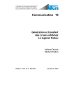
EMS: ENVIRONMENTAL MODELLING SUITE
SEDIMENT TRANSPORT MODULE
USER GUIDE
Margvelashvili N., Andrewartha J., Herzfeld M., Parslow J., Sakov P., Rosebrock U.
Version 1.0
CSIRO Marine and Atmospheric Research
GPO Box 1538, Hobart 7001
31.03.2003
Last updated: March 2011
1
1
2
3
4
5
6
INTRODUCTION ...................................................................................... 3
EMS STRUCTURE ................................................................................... 3
SEDIMENT PROCESSES ........................................................................ 4
INSTALLATION AND OPERATION ........................................................ 6
THE MODEL SET UP ............................................................................... 6
GENERAL MECOSED PARAMETERS ................................................... 6
6.1
Activate sediment module.................................................................. 6
6.2
Numerical grid ................................................................................... 6
6.3
Skin roughness .................................................................................. 7
6.4
Ripples............................................................................................... 7
6.5
Bottom friction .................................................................................... 8
6.6
Critical erosion stress ........................................................................ 9
6.7
Critical deposition stresses .............................................................. 10
6.8
Flocculation ..................................................................................... 10
6.9
Consolidation ................................................................................... 11
6.10 Biodiffusion ...................................................................................... 11
6.11 Initialisation diagnostic key .............................................................. 12
6.12 Maximum thickness of sediments .................................................... 12
6.13 Wave input....................................................................................... 12
6.14 Example........................................................................................... 13
7 TRACER SPECIFIC PARAMETERS ..................................................... 14
7.1
MECOSED tracers .......................................................................... 15
7.2
Initial concentrations ........................................................................ 16
7.3
Settling velocity ................................................................................ 17
7.4
Cohesive sediment .......................................................................... 17
7.5
Resuspension deposition................................................................. 17
7.6
Sediment grain density .................................................................... 17
7.7
Concentration of fresh sediment deposits........................................ 18
7.8
Flocculation key ............................................................................... 18
7.9
Example of the tracer specific parameters....................................... 18
7.10 Sorption/desorption ......................................................................... 19
7.11 Example for a sediment reactive tracer ........................................... 19
7.12 Diagnostic files ................................................................................ 20
8 BOUNDARY CONDITIONS.................................................................... 21
8.1
Example of a boundary condition .................................................... 21
9 FILE INVENTORY .................................................................................. 22
REFERENCES .............................................................................................. 24
2
1
INTRODUCTION
EMS is a general-purpose modelling package that simulates three-dimensional flow,
transport, and biogeochemical reactions in surface water. The model has been
developed at CSIRO Marine and Atmospheric Division and tested and refined
through a number of applications around the Australian coast. EMS comprises
hydrodynamic, sediment transport and biogeochemical reaction modules.
Hydrodynamics of EMS is based on a 3-d nonlinear nonstationary hydrostatic
approximation model SHOC (Herzfeld, 2008). The sediment model solves mass
balance equations for sediment concentrations in a coupled benthic and pelagic layers
taking into account bottom exchanges (Margvelashvili, 2008). Hydrodynamic and
sediment models provide physical settings to biogeochemical model, which updates
concentration of biogeochemical variables in water column and in sediments (Murrey
and Parslow, 1997; Wild-Allen et al., 2005)
This report is designed to assist the user in operating sediment module of EMS.
Theoretical and computational aspects of the sediment transport formulation are given
in (Margvelashvili, 2003). Scientific background and application manual for EMS
hydrodynamics can be found in (Herzfeld et al., 2002; Herzfeld and Waring, 2008).
2
EMS STRUCTURE
A general structure of EMS is illustrated in fig. 2.1. A 3-d hydrodynamic model is
coupled to 1-d sediment transport model via a number of interface routines. During
every simulation time-step these routines interrogate EMS (inquiring for
hydrodynamic variables plus benthic data) to initialise the 1-d sediment model and to
update forcing data. The sediment model then solves 1-d vertical advection-diffusion
equations for every column of the numerical grid. Within every grid column the
model solves equations for turbulent mixing in water column and bioturbation in
sediments, and simulates sediment settling, erosion/deposition, and consolidation of
sediments, plus vertical transport of the dissolved and sediment attached tracers.
Updated profiles are stored in 3-d arrays of EMS representing benthic and pelagic
layers. One way to think of the sediment module is that of a sewing machine coupling
benthic and pelagic layers together in a single integrated system. Once the
hydrodynamic and sediment transport steps are complete, EMS proceeds with the
biogeochemical model updating concentrations of biogeochemical variables in
benthic and pelagic cells.
When the sediment model is on, vertical diffusion and settling in a coupled benthic
pelagic system is handled by the sediment model routines. The hydrodynamic model
in this case simulates only horizontal diffusion and updates water velocities and 3-d
advection of tracers in water column.
3
Fig. 2.1 Schematic structure of EMS
3
SEDIMENT PROCESSES
Sediment module of EMS is based on a 1-d vertical model of coastal and estuarine
sediment transport - MECOSED (Margvelashvili, 2008). The model was intended as
an improvement to the transport simulation capabilities of a 3-d coastal
hydrodynamic/ water quality model MECO, developed at CSIRO, Division of Marine
Research (Walker & Sherwood, 1997). MECOSED simulates vertical transport of
particulate, dissolved, and sediment-bound tracers in water column and in sediment
bed (Fig. 3.1).
Fig. 3.1. Key sediment processes in MECOSED
Sediment transport
The sediment transport module of MECOSED solves advection-diffusion equations
for the mass conservation of suspended and bottom sediments, taking into account
bottom exchanges through the resuspension and deposition. Suspended particles
undergo turbulent mixing and settling due to gravity force. Displacement of particles
in sediment bed is driven by bioturbation and consolidation. The bioturbation is
represented by local diffusion. Empirical formulas are used to parameterise sediment
consolidation. Cohesive sediments are either eroded or deposited depending on
4
bottom shear stress and critical shear stress of the sediment resuspension and
deposition. A concept of equilibrium sediment distribution is utilized to parameterize
erosion/deposition of non-cohesive particles.
Dissolved transport
The module of the dissolved transport solves advection – diffusion equations of the
mass conservation of tracers dissolved in water column and in sediment bed.
Dissolved tracers undergo turbulent mixing in water column and diffusion in
sediments. Transport in water is coupled with benthic processes through the diffusion
across water and sediments and through the water entrainment/expulsion during
resuspension/deposition or consolidation events.
Sediment-bound tracers
The sediment-bound tracer is analogous to a hydrophobic contaminant, e.g. organic
chemical, heavy metal or radionuclide that adsorb to fine-grained sediment particles.
The model solves advection – diffusion equations for the mass conservation of the
sediment-bound tracers in water column and in sediment bed. Sorption exchange
between solid and liquid phases is calculated using the concept of the equilibrium
distribution. To simulate degradable pollutants, the model also incorporates first-order
decay reaction.
Bottom boundary layer
Bottom friction under combined wave-current flow is calculated from bottom
boundary layer model. On cohesive sediment bed constant physical roughness
associated with biogenic bed-forms is specified. On non-cohesive sediment bed the
total physical roughness is assumed to be composed of two components: one due to
skin friction over the sediment grains and another due to form drag over the ripples.
Ripples in a wave-dominated environment are either calculated or specified as the
model input data. Under combined waves and currents and in a current-dominated
flow the bed forms must be specified as the model input data.
Numerical solution
The numerical grid for sediment variables in the water column coincides with the
numerical grid of the hydrodynamic model. Within the bottom sediments horizontal
resolution of the model follows the resolution in water column. In vertical direction
the model utilises stretched sediment-thickness-adapted grid which allows for high
vertical resolution of the top sediments throughout the simulation.
The sediment model can run in a mode fully coupled to the hydrodynamic model and
in a transport mode when the sediment transport is simulated off-line, using precalculated velocities and diffusion coefficients. The model benefits from high order
numerical schemes developed in EMS. Curvilinear grids provide refined resolution in
areas with high spatial gradients. The model capabilities also involve multiply nesting
of the modelling domains (nested numerical grids), which gives a very high resolution
in areas of a particular interest at a relatively low computational costs.
5
The developed model is particularly suitable for representing fine sediment dynamics.
4
INSTALLATION AND OPERATION
All installation and operation procedures required by the sediment module are covered
by EMS installation requirements and can be found in SHOC user manual (Herzfeld
and Waring, 2008).
5
THE MODEL SET UP
All input data for the sediment model are stored in a single ASCII parameter file. This
file contains comments, key words, and values, and its contents completely describe a
particular model implementation and run parameters. Data structure and parameter file
format are exactly the same as used by the hydrodynamic module (Herzfeld and
Waring, 2008). In a typical application the development of the sediment model follows
the development of the hydrodynamic model. Throughout this document we assume
that the hydrodynamic step is complete and parameter file of the hydrodynamic model
is available (otherwise refer to SHOC manual describing the hydrodynamic model set
up (Herzfeld and Waring, 2008)).
To set up the sediment model, the hydrodynamic model parameter file must be
augmented with the sediment variables. The sediment data and parameters can be
broadly classified into initialisation data, boundary data, parameters specific to a
particular sediment tracer, and general sediment parameters. Detailed description of
this data is given in the next chapter.
The output variables from the sediment module are handled by EMS infrastructure
routines.
6
6.1
GENERAL MECOSED PARAMETERS
Activate sediment module
The sediment module of EMS is activated by adding the following command to EMS
parameter file:
DO_SEDIMENTS 1
The default option is do not activate the sediment code:
DO_SEDIMENTS 0
6.2
Numerical grid
The numerical grid for sediment variables in the water column coincides with the
numerical grid of the hydrodynamic model.
6
Numerical grid in sediments is defined by specifying initial thickness of every
sediment layer in meters, starting from the top layer. An example of the sediment
grid data is given below.
NSEDLAYERS
0.01
0.03
0.07
0.14
4
Here “NSEDLAYER” parameter gives the number of sediment layers, while the
column underneath lists the thickness of each layer sequentially starting from the top
layer. The top layer of the numerical grid represents an active layer of sediments and
its thickness remains constant throughout the simulation. The thickness of the
underlaying layers varies with time in response to sediment resuspension/deposition
and consolidation.
Constraints:
Numerical grid in sediments must include at least two sediment layers.
6.3
Skin roughness
Bottom skin roughness (in meters) associated with individual sediment grains is
specified by
Z0_SKIN
0.00001
The value of the skin roughness can be estimated as a median grain size (~Nikuradze
roughness height) divided by 30.
6.4
Ripples
Parameters PHYSRIPH, PHYSRIPL prescribe the ripple height and length (in meters)
on sandy sediments, respectively. The development of such ripples is associated with
the physical processes (waves and currents). The BIORIPH and BIORIPL parameters
provide dimension of ripples on a cohesive seabed, where ripples development is
typically associated with the biological reworking of the benthic layer.
PHYSRIPH
PHYSRIPL
BIORIPH
BIORIPL
0.02
0.6
0.005
0.2
Unless the ripple dimension is simulated, the model takes the largest out of the
PHYSRIPH and the BIORIPH as a representative ripple height and the largest out of
the PHYSRIPL and the BIRIPL as a representative ripple length.
7
Once the ripple dimension is specified, MECOSED proceeds with estimating bottom
roughness due to ripples according to Grant and Madsen (1982) formula.
In a wave dominated environment simulation of the ripple dimension can be activated
by
CALC_RIPPLES 1
In this case the model estimates the ripple height and length based on
Wakramanayake (1993) model. Ripples are estimated only over sandy sediments. On
a cohesive bed ripple dimension is specified as an input data from the parameter file
(see description of BIORIPH and BIORIPL parameters above).
The default option for estimating ripples is do not estimate the ripple dimension:
CALC_RIPPLES 0
In this case the ripple dimension must be specified in a parameter file.
Constraints:
An option for ripple calculation “CALC_RIPPLES 1” has never been used in our case
studies and remains largely untested. We recommend to use “CALC_RIPPLES 0” and
have the ripple dimension prescribed as the model input data.
6.5
Bottom friction
Two options are available in MECOSED to estimate bottom friction. One is based on
nonlinear Grant and Madsen model (Madsen 1994), which is activated by
BBL_NONLINEAR 1
The model requires wave/current data and bottom roughness as an input. The bottom
roughness is computed as a sum of the skin roughness and the roughness due to
ripples (see section 6.4). The wave/current data must be provided from the
hydrodynamic module.
An alternative option for calculating bottom friction is based on a linear bottom
boundary model activated by
BBL_NONLINEAR 0
With this option the bottom friction is approximated as a sum of the current friction
over the ripples and the wave friction over the sediments grains. There is no
interaction between waves and currents. The bedform roughness is used to estimate
friction of currents over the ripples, and the skin roughness is used to estimate wave
friction over the individual sediment grains.
The default option for bottom boundary layer model is Grant and Madsen model:
8
BBL_NONLINEAR 1
6.6
Critical erosion stress
Five options (CSS0, CSS1, CSS2, CSS3, CSS4) are available in MECOSED to
estimate critical shear stress on a cohesive sediment bed. A particular option can be
specified using the key CSS_ER_MODE. An example is given below.
CSS_ER_MODE
CSS0
The simplest CSS0 mode assumes constant critical shear stress. The value of this
constant can be specified as
CSS_ER 0.25
The default value of the critical erosion stress is 0.2 (N/m2).
In CSS1, CSS2, CSS3 modes critical shear stress is calculated as a function of the
sediment bed compactness using empirical formulations (5.5), (5.6), and (5.7),
respectively (see MECOSED scientific manual). Note that CSS1-3 options typically
imply that the sediment porosity varies with time due to consolidation processes.
An option CSS4 specifies the critical shear stress of erosion that varies with the
sediment depth. The shear stress values must be specified using the key CSS_ER. An
example is given below
CSS_ER 4
0.2
0.3
0.5
0.7
The corresponding depth levels (in m) are given by the key CSS_ER_DEPTH:
CSS_ER_DEPTH 4
-0
-0.002
-0.1
-0.2
In this example the critical shear stress of erosion is 0.2 N m-2 for sediments allocated
below 0 and above 0.002 m depth. The critical shear stress is 0.3 for sediments below
0.002 and above 0.1 m depth, and so on. Note than the number following CSS_ER
and CSS_ER_DEPTH keys now specifies the number of the sediment layers with a
distinct critical shear stress value.
Critical erosion stress for non-cohesive sediments is calculated as a quarter of the
sediment settling velocity. The reference height for the reference velocity is specified
at seven Nikuradze roughness heights (7*30* Z0_SKIN).
9
Constraints:
CSS1-3 options have never been tested in real world applications. An option CSS0 or
CSS4 is recommended.
6.7
Critical deposition stresses
Critical shear stress of cohesive sediment deposition (in N/m2) is given by
CSS_DEP
0.3
In a default mode cohesive sediments are always allowed to settle on the sediment
bed, e.g. CSS_DEP = +inf.
6.8
Flocculation
A number of options is currently available in MECOSED to calculate cohesive
sediment flocculation (FLOC0, FLOC1, FLOC4). A particular option is specified by
the key FLOC_MODE:
FLOC_MODE
FLOC0
The simplest FLOC0 mode assumes that sediments do not flocculate. FLOC1 mode
predicts mean floc velocities as a function of cohesive sediment concentration.
FLOC2 and FLOC3 modes are under construction and currently are not available.
FLOC4 mode is based on empirical formulation for settling velocity of cohesive
sediment derived from observations in the Brisbane estuary. The default mode is
FLOC0, i.e. sediments do not flocculate.
If the flocculation mode FLOC1 is on:
FLOC_MODE
FLOC1
two additional parameters must be specified
FLOC_PRM1 1.
FLOC_PRM2 2.
Here FLOC_PRM1 is a scaling parameter and FLOC_PRM2 is a power of the
exponential term in a power low approximation of the sediment flocculation (see
formula (5.2) in the MECOSED science manual).
An option
FLOC_MODE
FLOC4
FLOC_PRM1 2e-4
makes the model to estimate settling velocity of the sediment flocs using an empirical
relationship based on observations in the Brisbane estuary and Moreton Bay (see
10
formula 5.4 in the MECOSED science manual). The parameter FLOC_PRM1 in this
case represents settling velocity of the individual sediment grains in (m s-1).
All flocculation modes involve scaling of the settling velocity by the water salinity, so
that there is no flocculation when the water salinity is less than 0.1 ppm. The
flocculation of a particular sediment fraction is controlled by additional tracer-specific
parameter TRACER#.floc which is described in section 7.8.
Constraints:
FLOC1 and FLOC4 options require salinity to be included in the list of the
hydrodynamic model variables.
6.9
Consolidation
Consolidation of sediments is activated by
CONSOLIDATE 1
If this indicator is on then the model requires also data on final minimal porosity of
sediments (FINPOR_SED, non-dimensional), and typical time scale of the sediment
bed consolidation (CONSOLRATE, in days):
FINPOR_SED
CONSOLRATE
0.3
5.e+0
The default option is no consolidation:
CONSOLIDATE 0
Constraints:
We have never used consolidation option in our case studies. An option
“CONSOLIDATE 0” is recommended.
6.10 Biodiffusion
Biological activity of the benthic layers is given by the parameter
BIODENS
100.0
which prescribes the number of standard animals per square metre of sediments.
Maximum depth for the biological activity (in meters) is specified as
MAXBIODEPTH
0.2
Diffusion coefficients for bio-turbation (BT_PARTIC_KZ, in m2/s) and bio-irrigation
(BI_DISSOL_KZ, in m2/s) of sediments are scaled by the amount of biological
activity present (m2/s per animal/m2), and also decrease with depth in sediment bed
11
according to some fixed profile. Diffusion coefficients in the sediment bed are
specified as follows
BI_DISSOL_KZ
BT_PARTIC_KZ
1.0e-10
1.0e-10
Diffusion coefficients across sediment – water interface are given by
BI_DISSOL_KZ_I
BT_PARTIC_KZ_I
1.0e-12
1.0e-12
Functional form of the scaling profile for bioirrigarion and bioturbation activity as a
function of depth is prescribed by one of the following strings: constant, linear,
parabolic, gaussian:
BIOSEDPROFILE
parabolic
6.11 Initialisation diagnostic key
The key
VERBOSE_SED 1
downloads “sedlog.txt” file containing sediment initialisation diagnostics.
The default option is no diagnostics.
6.12 Maximum thickness of sediments
The maximum thickness of sediments can be specified by
MAX_THICK_SED 2
There is no feedback in EMS from the sediment processes to the hydrodynamic
model, so that any changes in the sediment thickness do not translate into the
corresponding changes of the water depth. An implicit assumption underlying this
approximation is that changes in the sediment thickness are small compared to the
water depth. This assumption can be violated particularly during long-term
simulations. To avoid unrealistic situations where the sediment thickness exceeds the
water depth we introduce the parameter MAX_THICK_SED. Sediment particles are
not allowed to settle on the seabed in areas where the sediment thickness has reached
the maximum predefined value.
6.13 Wave input
Wave input is represented by the amplitude of the near bottom wave orbital velocities
(m s-1), wave period (s) and wave direction (degrees). The direction angle is given as
12
degrees Cartesian referenced to the West-East direction counter-clockwise. The wave
data are updated at time intervals given by WAVE_VARS_INPUT_DT:
WAVE_VARS_INPUT_DT 1 hour
The wave-data source-file is specified through the key WAVE_VARS:
WAVE_VARS
waves.nc
The default option is no waves.
6.14 Example
Example of EMS parameter-file section that specifies general
parameters of the sediment model is given below.
#####################################################################
#######
# Sediments
VERBOSE_SED 1
# Sediment layers thickness
NSEDLAYERS 3
0.005
0.015
0.19
# Activate sediment process
Default: 0
DO_SEDIMENTS
1
# CRITICAL STRESSES
# Critical shear stress of cohesive bed erosion (N m-2)
# Modes: CSS0, CSS1, CSS2, CSS3
# Default: CSS0: css_er = 0.2
CSS_ER_MODE
CSS0
CSS_ER
0.05
# Critical shear stress of cohesive sediment deposition (N m-2)
# Default: CSS_DEP = +inf
#CSS_DEP
0.3
# FLOCCULATION
# Modes: FLOC0, FLOC1
# Default: FLOC0 - no flocculation
FLOC_MODE
FLOC1
FLOC_PRM1 300
FLOC_PRM2 3
# CONSOLIDATION
CONSOLIDATE 0
FINPOR_SED 0.4
CONSOLRATE
10.e+0
13
# Bottom Boundary Layer model
BBL_NONLINEAR 1
# Bottom Skin roughness (m)
Z0_SKIN 0.00003
# RIPPLES
# Default: 0
PHYSRIPH
PHYSRIPL
BIORIPH
BIORIPL
0.03
0.6
0.005
0.2
# Maximum depth for biological activity (m)
MAXBIODEPTH 0.2
# Functional form for bioirrigarion and bioturbation activity
# as a function of depth. Currently can be one of:
#
constant
#
linear
#
parabolic
#
gaussian
# Only the first letter of this parameter is significant
BIOSEDPROFILE
parabolic
# Biological activity (standard animals per square metre?)
BIODENS
10.0
# Diffusion coefficient for bio-irrigation of sediments.
# This value is scaled by the amount of biological
# activity present, and also decreases with depth
# in the sediment according to some
# fixed profile. The value here is the value which
# would apply at zero depth in the sediment.
# Units are m2 s-1 per animal per m2.
BI_DISSOL_KZ
1.0e-9
BI_DISSOL_KZ_I
1.0e-9
# Diffusion coefficient for bio-turbation of sediments.
# This value is scaled by the amount of biological
# activity present, and also decreases with depth
# in the sediment according to some
# fixed profile. The value here is the value which
# would apply at zero depth in the sediment.
# Units are m2 s-1 per animal per m2.
BT_PARTIC_KZ
1.0e-10
BT_PARTIC_KZ_I
1.0e-12
#####################################################################
#####
# Activate Waves
DO_WAVES YES
WAVES_DT 1 hour
WAVE_VARS YES
#WAVES BOT_STRESS VERT_MIX
7
TRACER SPECIFIC PARAMETERS
14
Apart from the general model parameters each tracer of EMS has its own set of the
tracer specific parameters. A general guideline for tracer specification in EMS can be
found in (Herzfeld and Waring, 2008). This chapter describes tracer parameters
specific to MECOSED.
7.1
MECOSED tracers
MECOSED calculates transport of two basic types of tracers: particulate and
dissolved (fig 7.1). Particulate tracers represent either volumetric particles or zerovolume tracers. Volumetric particles settle due to gravity force and change porosity in
water column and in sediment bed. The concentration of volumetric particles is
limited by free volume available in water column or in sediment bed.
Zero-volume particles are assumed to occupy zero volume in space. A typical
example of zero-volume tracer is a sediment-attached tracer (pollutant). As any
particulate tracer the sediment-attached tracer undergoes settling and
resuspension/deposition in water column and bioturbation/consolidation in sediments
but unlike to sediments it does not change porosity of the sediment layer.
It is recommended to treat also biogeochemical reaction variables as zero volume
tracers, so that any transient instabilities in biogeochemical model simulations do not
blow away the sediment layer.
Fig. 7.1 MECOSED tracers
Every MECOSED tracer must be specified as either particulate tracer
TRACER4.partic 1
or dissolved tracer
TRACER4.dissol 1
15
The volumetric tracer can be specified using the following string:
TRACER4.calcvol 1
Default value for “calcvol” is zero and the traces is considered as having zero volume
of constituting particles. If the flag calcvol is on (volumetric tracer) then the tracer is
not allowed to attach to any sediment fraction (adsorb = 0).
7.2
Initial concentrations
Initial concentration of each sediment fraction is specified individually for each tracer in a
tracer description filed. To indicate that a particular tracer is present in both water column and
sediments, a type indicator must be added to the tracer description list
TRACER#.type WATER SEDIMENT
Then the concentration units are specified by
TRACER#.units kg m-3
This is followed by valid range of the concentrations in water and in sediments
TRACER#.valid_range_wc 0 1000
TRACER#.valid_range_sed 0 3000
Finally the initial concentrations of the tracer in water and in sediments is specified by
TRACER#.fill_value_wc 0.01
TRACER#. fill_value_sed 600
Spatially varying fields of the initial sediment deposits can be specified through the
interpolation of observations. Observations must be stored in an ASCII file (for instance
init_deposit.txt file) with the first and second columns representing longitude and latitude of
the sampling site respectively and the rest columns showing observed concentrations.
TRACER#.data_sed
TRACER#.interp_type
init_deposit.txt
linear
The data file format is the same as that used for boundary data (see section 8.1). The
interpolation type is given by the key TRACER#.interp_type.
Constraints:
If the concentration units for sediments and dissolved tracers differ from “kg m-3” then the
model assumes that the concentration is given in “mg m-3” (except for sediment attached
pollutants). Concentration of the sediment-attached tracers must be given as some activity per
unit volume (Activity m-3) rather than per unit mass.
It is recommended to keep initial concentration of all sediment fractions within the reasonable
bounds so that to insure that initial porosity of sediments exceeds 0 but is lower than 1.
Benthic layer of MECOSED must always include some sediment particles. In applications
with a high-energy environment it is recommended to include in MECOSED a sediment class
16
representing heavy particles (eg gravel fraction) that would form a baseline un-erodible
substrate underlying fine sediments.
EMS typically does not resolve bed-load transport layer. Z-coordinate grids produce step like
representation of bathymetry. Hence, the developed 3-d sediment module is particularly
suitable for simulating transport of only fine sediments.
If the sediment flocculation is on, the salinity field must be specified in both benthic
and pelagic layers (eg. TRACER#.type WATER SEDIMENT).
7.3
Settling velocity
Settling velocity of the particulate tracer is given by
TRACER4.svel
–0.001
Default is 0.
This parameter specifies settling velocity of the individual sediment grains. When
sediments flocculate the settling velocity of the flocs is estimated through the
flocculation model and the largest of the two (the settling velocity of the individual
grains and the settling velocity of the flocs) is used to settle sediment particles.
7.4
Cohesive sediment
MECOSED employs two different formulations for sediment resuspension on
cohesive and non-cohesive sediment bed. A particular sediment resuspension regime
could be specified by assigning zero (non cohesive) or unit (cohesive) value to
“cohesive” flag:
TRACER4.cohesive 1
Default value is cohesive.
7.5
Resuspension deposition
Resuspension and deposuition of any particular tracer is controlled by “resuspend”
and “deposit” flags:
TRACER4.resuspend 1
TRACER4.deposit 1
Default is resuspend and deposit. If both “resuspend” and “deposit” flags are off, then
there is neither resuspension nor deposition of particles across water and sediments.
Note that unless diffusion fluxes across water and sediments is switched off (see
section on 6.10 on Biodiffusion), benthic and pelagic layers in this case are not fully
decoupled.
7.6
Sediment grain density
17
Density of sediment grains (kg/m3) is specified by
TRACER4.b_dense 2.65e+03
The sediment grain density (along with the mass concentration and the grid cell
volume) is used to calculate the seabed porosity.
7.7
Concentration of fresh sediment deposits
Concentration of fresh sediment deposits (kg/m3) is given by
TRACER4.i_conc 1.2e+03
This parameter is used to estimate the volume of water trapped in sediments during
the deposition event.
7.8
Flocculation key
Flocculation of individual tracers can be switched on or off with the following flag
TRACER4.floc 1
Default is 0 (no flocculation).
7.9
Example of the tracer specific parameters
This section shows an example of the tracer specifications for sediment particles
TRACER4.name Silt
TRACER4.long_name Silt fraction
TRACER4.type
WATER SEDIMENT
TRACER4.units kg m-3
TRACER4.valid_range_wc 0 1e+35
TRACER4.valid_range_sed 0 1e+35
TRACER4.diagn 0
TRACER4.fill_value_wc 0.0
TRACER4.fill_value_sed 600.0
TRACER4.dissol 0
TRACER4.partic 1
TRACER4.advect 1
TRACER4.diffuse 1
TRACER4.decay 0
TRACER4.b_dens 2.65e+03
TRACER4.i_conc 1.2e+03
TRACER4.svel -0.2e-3
TRACER4.cohesive 1
TRACER4.calcvol 1
TRACER4.floc 1
TRACER4.resuspend 1
TRACER4.deposit 1
18
7.10 Sorption/desorption
Any particulate (partic 1) zero-volume (calcvol 0) tracer in MECOSED can be
attached to any other particulate (partic 1) volumetric (calcvol 1) tracer by specifying
“adsorb” flag (1 if adsorbed, 0 if not adsorbed).
TRACER4.adsorb 1
and indicating the name of the sediment class carrying this particular adsorbed tracer
TRACER4.carriername Clay
The above strings indicate that the tracers N4 is attached (adsorbed) to the tracer
called “Clay”. The tracer “Clay” must represent some particulate volumetric tracer.
To simulate sorption/desorption exchange between particulate and dissolved fractions
of the sediment reactive tracer, the user ought to indicate the corresponding dissolved
fraction and specify sorption parameters.
The dissolved fraction of the sediment reactive tracer is identified by the parameter
“dissolvedname” indicating the name of the dissolved tracer:
TRACER4.dissolvedname ZincDis
The above strings indicate that the sediment reactive tracer N4, attached to the
sediment tracer “Clay”, has the dissolved counterpart “ZincDis”.
An equilibrium distribution constant for the desorbed and adsorbed fractions of the
sediment reactive tracer is specified by the parameter “adsorbkd” (in m3/kg)
TRACER4.adsorbkd 20
And the adsorption rate constant (in days) is given by
TRACER4.adsorbrate 1
MECOSED employs first order kinetic reaction to simulate sorption/desorption reactions
between particulate and dissolved fractions of the sediment reactive tracer (equations 7.3, 7.4,
MECOSED science manual). Note that concentrations of the sediment reactive tracers are
given as an activity per unit volume, rather then per unit mass.
7.11 Example for a sediment reactive tracer
This section gives an example of the tracer specifications for the
sediment reactive tracer.
TRACER6.name ZNclay
TRACER6.long_name Zn on clay
TRACER6.type
WATER SEDIMENT
19
TRACER6.units g m-3
TRACER6.valid_range_wc 0 1e+35
TRACER6.valid_range_sed 0 1e+35
TRACER6.diagn 0
TRACER6.fill_value_wc 0.0
TRACER6.fill_value_sed 0.0
TRACER6.dissol 0
TRACER6.partic 1
TRACER6.advect 1
TRACER6.diffuse 1
TRACER6.b_dens 2.65e+03
TRACER6.i_conc 1.2e+03
TRACER6.decay 0
TRACER6.adsorb 1
TRACER6.carriername Clay
TRACER6.dissolvedname ZincDis
TRACER6.adsorbkd 20
TRACER6.adsorbrate 1
7.12 Diagnostic files
A number of 3d and 2d diagnostic variables specific to sediment processes can be
added to the stream of the model output by specifying extra diagnostic tracers in the
parameter file. The diagnostic tracer is identified by the key (TRACER#.diagn 1).
The 3d diagnostic variables specific to sediments are
“tss”:
total suspended sediment concentration in water and in sediments,
“svel_floc”: settling velocity of the sediment flocs in water column, and velocity of
consolidating particles in sediments;
“porosity”: porosity in water and porosity in sediments;
“cohsed”: cohesive sediment fraction given as a mass percentage of cohesive
sediments relative to the total mass of either suspended or bottom
sediments.
A particular 3-d variable is identified by its name (for example “tss”). Note that the
sediment settling velocity is estimated in the model as the largest of the settling
velocity of individual grains and the settling velocity of flocs, so that if there are no
flocs present (svel_floc = 0) sediments still settle due to gravity force acting on the
individual sediment grains. Porosity in water column is always assumed to be equal to
1.
All 3d diagnostic variables must be specified as of WATER SEDIMENT type.
2d diagnostic variables include:
“ustrcw_skin” bottom shear stress velocity (m s-1)
“depth_sed” sediment thickness (m)
“dzactive”
thickness of the top active layer of sediments (m)
“hripple”
ripple height (m)
“lripple”
ripple length (m)
All 2d diagnostic variables must be specified as of BENTHIC type.
20
An example bellow illustrates specification of the 3d and 2d diagnostic variables:
TRACER7.name tss
TRACER7.long_name tss
TRACER7.type
WATER SEDIMENT
TRACER7.units kg m-3
TRACER7.valid_range_wc 0 1e+35
TRACER7.valid_range_sed 0 1e+35
TRACER7.fill_value_wc 0.0
TRACER7.fill_value_sed 0.0
TRACER7.advect 0
TRACER7.diffuse 0
TRACER7.diagn 1
TRACER8.name ustrcw_skin
TRACER8.long_name ustrcw_skin
TRACER8.type
BENTHIC
TRACER8.units m s-1
TRACER8.valid_range_wc 0 1e+35
TRACER8.valid_range_sed 0 1e+35
TRACER8.fill_value_wc 0.0
TRACER8.fill_value_sed 0.0
TRACER8.advect 0
TRACER8.diffuse 0
TRACER8.diagn 1
An extra diagnostics can be inferred from the model output through the development
of customised processing scripts interrogating netcdf files produced by the model
(tracers in sediments in the output files are identified by suffix “_sed” added to the
tracer name).
8
BOUNDARY CONDITIONS
MECOSED assumes no sediment fluxes through the water surface, at the bottom of the
benthic layer, and at the lateral land boundaries. To specify sediment concentrations at the
open sea lateral boundaries, data file must be provided and referenced to in the list of the
boundary condition specifications. For more details on open boundary specification for
tracers please refer to SHOC manual (Herzfeld and Waring, 2008)
8.1
Example of a boundary condition
This section includes an example of the boundary conditions for hydrodynamic and
sediment variables at the open sea boundary. Features relevant to MECOSED are
highlighted in bold. The parameters “BCOND_TRA3” and “BCOND_TRA4”
indicate that the boundary data for tracer 3 and tracer 4 are specified in data files. The
location of this data file “bnd_ocean.ts” is indicated by the 3rd highlighted line.
BOUNDARY0.NAME
north
BOUNDARY0.TYPE
u1
BOUNDARY0.BCOND_NOR
CUSTOM
BOUNDARY0.CUSTOM.u1
uv_to_u1
/home/mgdata/dent/c2_mgs/run6_coarse_uv_n.nc
BOUNDARY0.BCOND_TAN
CLAMPD
21
BOUNDARY0.CUSTOM.u2
uv_to_u2
/home/mgdata/dent/c2_mgs/run6_coarse_uv_t.nc
BOUNDARY0.BCOND_ELE
NOTHIN
BOUNDARY0.BCOND_TRA_ALL NOGRAD
BOUNDARY0.BCOND_TRA0 FILEIN
BOUNDARY0.BCOND_TRA1 FILEIN
BOUNDARY0.BCOND_TRA2 NOGRAD
BOUNDARY0.BCOND_TRA3 FILEIN|UPSTRM
BOUNDARY0.BCOND_TRA4 FILEIN|UPSTRM
BOUNDARY0.BCOND_VZ
NOGRAD
BOUNDARY0.BCOND_KZ
NOGRAD
BOUNDARY0.DATA
/home/mgproja/dent/st_meco/ctd_station1.nc
/home/mgproja/sedi_mgf/huon/3d/bnd_ocean.ts
BOUNDARY0.INVERSE_BAROMETER FALSE
BOUNDARY0.POINTS
2
53 12
53 13
An example of the open sea boundary data file (“bnd_ocean.ts”) is given below.
## COLUMNS 3
##
## COLUMN1.name Time
## COLUMN1.long_name Time
## COLUMN1.units days since 2001-06-01 00:00:00 +10
## COLUMN1.missing_value -999
## COLUMN1.fill_value 0.0
##
## COLUMN2.name Sand
## COLUMN2.long_name Sand
## COLUMN2.units kg s-1
## COLUMN2.missing_value -999
## COLUMN2.fill_value 35
##
## COLUMN3.name Silt
## COLUMN3.long_name Silt
## COLUMN3.units kg s-1
## COLUMN3.missing_value -999
## COLUMN3.fill_value 35
##
-1e13 0.0 0.01
1e13 0.0 0.01
9
FILE INVENTORY
The sediment model file inventory is shown in table 9.1.
N
Filename
Description
1
2
3
4
5
6
7
sed_init.c
Hyd2sed.c
Sed2hyd.c
Bbl.c
Vtransp.c
Trvdiffsettl.c
sediments.c
MecoSed initialisation routine.
Data flow from EMS to mecosed
Data flow from mecosed to EMS
Bottom boundary layer model
Vertical transport in water column and sediment bed
Implicit vertical diffusion, settling, erosion/deposition.
Sediment step file
22
8
Sediments.h
Include file for mecosed structures
Table 9.1 MECOSED file inventory
23
REFERENCES
Herzfeld, M., Waring, J., Parslow, J., Margvelashvili, N., Sakov, P., Andrewartha, J.,
2008. SHOC: Sparse Hydrodynamic Ocean Code Science manual. CSIRO internal
document. 121 p.
Herzfeld, M., Waring J. R., 2008. SHOC: Sparse Hydrodynamic Ocean Code User’s
manual. CSIRO internal document, 128 p.
Herzfeld M. 2006. An alternative coordinate system for solving finite difference
ocean models. Ocean Modelling 14, 174-196.
Margvelashvili, N., 2003. “MECOSED – Model for Estuarine and Coastal Sediment
Transport, Scientific Manual”, CMAR internal document, 46 p.
Margvelashvili, N., 2009. Stretched Eulerian coordinate model of coastal sediment
transport. Computers and Geosciences, 35, 1167-1176.
Murray, A. G., Parslow, J. S., 1997. Port Phillip Bay Integrated model: Final Report.
Port Phillip Bay Environment Study Technical Report No. 44, Melbourne.
Walker S.J., Sherwood C.R., 1997. A transport model of Port Phillip Bay. CSIRO,
Division of Oceanography, Technical Report 39, 59 p.
Wild-Allen, K., J. Parslow, M. Herzfeld, P. Sakov, J. Andrewartha & U. Rosebrock,
2005. Biogeochemical Modelling of the D’Entrecasteaux Channel and Huon Estuary.
Technical Report, CSIRO Marine & Atmospheric Research,113 p.
24