1
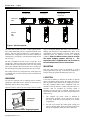
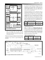
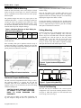
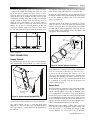
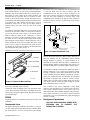
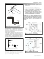
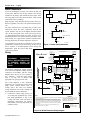
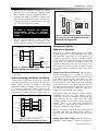
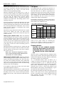
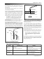
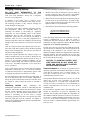
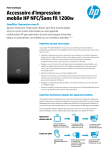
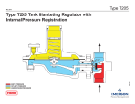
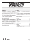
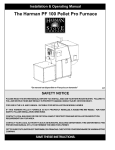
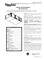
Bulletin 30-10 / Nov. 2010
INSTALLATION MANUAL
M1218 FAN COIL
NOTICE TO INSTALLER AND EQUIPMENT OWNER: RETAIN THIS MANUAL AT THE JOB
General The information on the following pages is to help the
installer save time, provide the best possible installation and insure
continuous trouble-free operation.
Scope These instructions apply to the Unico M1218 Fan Coil
unit. Installation instructions for the air distribution system are
covered in other bulletins. Before beginning any installation, a
detailed system layout must be done in accordance with Bulletin
40-40 System Sizing and Layout bulletin.
SUFFICIENT
BUILDING
INSULATION
IS
ESSENTIAL FOR THE MOST ECONOMICAL
OPERATION
Il00159.CV5
General Precautions and Safety Tips Do not attempt to
install or startup unit without first reading and understanding the
appropriate sections in this manual. Before operating, be sure the
unit is properly grounded.
TABLE OF CONTENTS
INTRODUCTION ........................................................ 1
UNPACKING .............................................................. 2
LOCATION ................................................................. 2
SECONDARY DRAIN PAN ........................................ 3
MOUNTING ................................................................ 4
Horizontal Platform............................................... 4
Horizontal Suspended .......................................... 4
Ceiling .................................................................. 4
Vertical ................................................................. 5
DUCT CONNECTION................................................. 5
Supply Plenum ..................................................... 5
Return Duct .......................................................... 5
PIPING ....................................................................... 6
Condensate Lines ................................................ 6
Refrigerant Lines .................................................. 7
Expansion Valve ................................................... 7
Water Connections ............................................... 8
WIRING ...................................................................... 8
CHARGING AND STARTUP ...................................... 9
Sequence of Operation ........................................ 9
Fan Speed........................................................... 10
Checking Airflow ................................................. 10
Charging a Cooling System ............................... 12
Low Ambient Control Kit...................................... 13
Charging a Heat Pump System ........................... 13
Mild Weather Kit .................................................. 14
APPENDIX A - Hot Water Coil Capacities ................. 15
APPENDIX B – Chilled Water Coil Capacities .......... 15
APPENDIX C - Specifications ................................... 16
Installation should be in accordance with all local codes and
regulations and with the National Fire Protection Association and
Underwriters Laboratories applicable standards and regulations. In
case of conflict, local codes take precedence.
All electrical wiring should be in accordance with the latest edition
of the National Electrical Code and all local codes and regulations.
Condensate piping should be installed in accordance with
governing code.
Always install a secondary drain pan when an overflow of
condensate could cause damage.
Part Numbers This manual does not always include the
latest revision letter when referring to UPC part numbers.
Refer to the latest Price List and Spec Sheets for the current
UPC revision letter. For example, UPC-00A where A is the
latest revision.
INTRODUCTION
The Unico System is a complete indoor comfort system that
includes an indoor fan coil unit and small duct system. The
fan coil unit and duct system were designed to operate
together to provide the proper airflow in every installation.
The conditioned air is supplied through a series of two-inch
diameter ducts as a stream of air that entrains and mixes
with the room air. This process of aspiration produces a
more even temperature distribution in the room than a
conventional system.
CM
C
US
CERTIFIED TO UL STD 1995
CONFORMS TO CAN/CSA STD
C22.2 NO. 236
81037
Copyright © 2010 Unico, Inc.
Bulletin 30-10 — Page 2
Heating Only
Cooling Only
Heating and Cooling
Blower Cabinet
+ Hot Water Coil)
Blower Cabinet
+ Cooling Coil
Blower Cabinet
+ Hot water Coil
+ Cooling Coil
Horizontal
Flow
OUT
IN
Vertical
UpFlow
IL00148.CV5
Figure 1. Unit Arrangement
The Unico M1218 Fan Coil unit is a single packaged unit.
The cooling and heating coils are contained within the same
cabinet. The unit can be mounted in a vertical-upflow or
horizontal-flow configuration. The coils can be combined as
a heating-only, cooling-only, or heating and cooling fan coil
unit. See Fig. 1.
The unit is available in one size; 38-in L x 20-in W x 12-in
H (965-mm x 508 mm x 305-mm). The heating only system
includes the blower/motor and a hot water coil. The cooling
only system includes the blower/motor and a cooling coil.
For the heating and cooling system both coils are provided.
The cooling coil may be a refrigerant coil, a heat pump coil,
or a chilled water coil. The electrical panel is located inside
of the cabinet.
signs of concealed damage and notify carrier of any such
damage. All materials are sold FOB Factory and it is the
responsibility of the consignee to file any claims with the
delivering carrier for materials received in a damaged
condition. Open the blower access panel to remove
the motor shipping support. See Fig. 2. . The
expansion valve is shipped loose and is located in
the coil compartment near the connections.
MOUNTING
The unit comes factory ready for horizontal or vertical
airflow applications (see Fig. 1) and may be mounted to a
structure using the optional mounting rails (UPC 95).
LOCATION
UNPACKING
All units are inspected prior to shipping and are carefully
packaged in individual cartons. Inspect all cartons prior to
unpacking. Notify carrier of any damage.
Open the carton to remove the unit. Inspect unit for visible
Locate the air handler to minimize the number of plenum
elbows and fittings while keeping the supply duct runs as
short as possible. (See Bulletin 40-30, Component Layout).
The fully insulated cabinet allows installation with zero
clearance to the top, bottom, or sides of the unit. However,
clearance must be provided for servicing which is
dependent on how the unit is installed. Servicing of the
blower/motor assembly and coils can be performed in three
different ways:
1.
The complete top panel, which is attached to
blower/motor assembly, can be removed. To do this,
the motor leads must be disconnected in the control
compartment.
2.
For side access remove the control panel, cooling coil
panel, or heating panel which are located on the same
side as the refrigerant, drain, and water connections.
CARDBOARD
SUPPORTS
Figure 2. Location of Motor Shipping Supports
Copyright © 2010 Unico, Inc.
Bulletin 30-10 — Page 3
1 (25) Minimum
Side View
Supply plenum
12
"
Air Flow
Return Duct
38
"
Air Flow
1 (25) Minimum
Supply Plenum
Top View
20
"
Return Duct
38
"
24(610) side
clearance for service
The standard return duct is 10 feet (3 m) in length so it may
have to be cut to avoid bunching if the distance to the unit is
significantly less than 100 inches. If needed, up to two
return ducts can be coupled to make a 20-ft (6-m) duct. The
minimum length should be 6 feet (2 m). When given a
choice, maximize the distance and make at least one 90°
bend for the best sound attenuation.
Each unit is designed to fit into a small space where a
conventional unit could not be used. The 12-in. height
allows the unit to fit through joists or studs spaced at least
16-inches (406 mm) on center. If no access is provided, an
opening must be cut. It is suggested to use the opening
required for the return air box, especially in an attic
installation. The opening size for the return air box is listed
in Table 1. If the joists or studs are significantly less than 16
inches (406 mm) center-to-center or running the wrong
direction it would be necessary to cut and header the joists.
Table 1. Return Air Box Opening
Suspended Installation
Side View
Supply plenum
Air Flow
12
"
18 (457) bottom
clearance for
service
1218
UPC-01-1218
Size of Opening
Inches (mm)
14 3/8 x 20 ½
(365 x 521)
Secondary Drain Pan
IL00149.CV5
Figure 3. Minimum Clearances
3.
Return Air Box Part No.
Return Duct
38
"
All dimensions in inches (mm).
Model
Where the unit is suspended or mounted on the wall
using the mounting rails, the panel below the
blower/motor assembly can be removed for servicing.
In this case access to the coils must be from the side
access panels. See Fig. 3.
Position the return air box and filter near the unit allowing
at least one 90° bend in the return duct for proper acoustical
performance. Fig. 4 shows a typical horizontal attic
installation
Where an overflow of condensate could cause water
damage, a secondary drain pan MUST BE INSTALLED.
Place the drain pan on the mounting base, platform or angle
iron support frame. Be sure to allow enough room for the
drain line and connection (refer to Table 2). The unit should
be placed over the secondary drain pan. Use rubber pads for
isolation to raise the unit high enough in the secondary
drain pan for the drain line to clear the side.
Table 1. Secondary Drain Pan
Unit Size
Part No.
Dimensions
inches (mm)
M1218
UPC-94
42 x 24
(1066 x 610)
† NOTE — The drain fitting extends 7/8 inch (22 mm) beyond this dimension.
Figure 4. Typical Horizontal Attic Installation, M1218
Copyright © 2010 Unico, Inc.
Bulletin 30-10 — Page 4
Horizontal Platform Mounting
Mount the unit horizontally when vertical height is limited
such as in an attic or crawl space. It is easiest to mount the
unit on a platform but care must be taken to assure proper
drain line pitch.
The platform height must allow for proper pitch of the
condensate drain lines — at least ¼ inch drop per lineal foot
(20 mm per meter). The platform can be built from a sheet
of ½ inch (13 mm) plywood and stud frame. Table 3. Lists
the maximum horizontal drain line run for various framing
materials and still provide adequate drainage.
Table 2. Horizontal Distance of Drain Piping for
Different Framing Materials
Frame Lumber:
2x4
2x6
2x8
2 x 10
Max. Horizontal Run,
ft. (m)
18 (5)
26 (8)
34 (10)
42 (13)
The platform size should be a minimum of 24 x 42 inches
(610 x 1066 mm).
Place secondary drain pan on platform and unit on top of
isolation pads inside of secondary drain pan. Be sure that
the unit is raised high enough in the drain pan to allow for
primary drain line condensate connection.
hooks as applicable to attach the chains or cables to the unit
and the ceiling.
Place the unit inside of the secondary drain pan as you
would for platform support with the angle iron supports
lengthwise under the secondary drain pan. Level the unit by
adjusting the length of the chains or cables.
If using the alternative method, hang the secondary drain
pan from the unit using self-tapping screws and metal straps
or wires. Adjust the straps or wires to pitch the secondary
drain pan toward the drain connection.
Ceiling Mounting
If desired, the unit can be mounted flush to the ceiling (see
Fig. 7) using the optional mounting rails (UPC–95).
Remove top screws from both sides of the unit. Align holes
on mounting rails with the holes on the unit. Fasten
mounting rails to the unit with the screws that were
removed earlier. Attach unit to a structural member. Refer
to Fig. 8 for the screw hole pattern. Suspend secondary
drain pain from the unit with metal straps or wires.
Figure 6. Typical Horizontal Suspension
Mounting
Joist
Ceiling
Figure 5. Typical Platform Installation
Mounting Rails
Unit
Horizontal Suspended Mounting
The unit can also be suspended from the ceiling or rafters.
The preferred method is to support the unit and the
secondary drain pan from underneath with angle iron
supports (see Fig. 6). As an alternative, the unit can be hung
with the mounting rails.
CAUTION. DO NOT HANG UNIT FROM TOP
OF CABINET IF NOT USING MOUNTING
RAILS TO AVOID DAMAGING THE
EQUIPMENT.
Use either four (4) chains or steel cables with 80 lbs. (36
kg) test strength to hang the unit. Use eyebolts and ‘J”
Copyright © 2010 Unico, Inc.
Metal Straps or Wires
Secondary Drain Pan
IL00164.CV5
Figure 7. Typical Ceiling Mounting
Vertical Rail Mounting
The unit can only be mounted in the vertical up-flow
configuration. The vertical rail mounting method is shown
in Figure 9. Mark hole pattern on wall and install stud
screws or lag screws (see Fig. 8).
Bulletin 30-10 — Page 5
To install the unit vertically, such as in a closet, basement,
or utility room, attach the mounting rails (UPC 95) to the
top of the unit as explained previously. Screw or nail a
temporary board to the wall at the bottom of the location
where the unit will be mounted. The unit will rest on this
board during mounting. If the wall covering is not adequate
enough to hold the weight of the unit, use lag screws to
attach the rails to the structure. Use six (6) lag screws a
minimum of 3 inches (77 mm) long, which will be screwed
directly into a stud or structural member. If the wall
covering is sufficient, toggle screws may be used to mount
the unit. The board can be moved when the mounting of the
6x
5
A 6-in plenum can be used so long as a 7-in duct is attached
to the unit and is then reduced at least 4-ft from the unit.
To attach the plenum adapter to the unit, align the holes on
the adapter with the holes located around the supply outlet
on the unit. Mount the adapter with six (6) sheet metal
screws. See Figure 10.
Attach the plenum to the adapter by inserting it over the
collar. Use three (3) or four (4) equally spaced sheet metal
screws to secure the duct to the collar and then tape around
the seam with UL 181A aluminum tape. Then wrap the 1-in
fiberglass blanket duct insulation around the adapter and
seal with UL 181A aluminum tape.
16
Blower
Cabinet
IL00171.CV5
Figure 8. Screw Hole Pattern of Mounting
unit is completed.
Plenum Adapter
DUCT CONNECTION
Supply Plenum
Plenum
Insulation Wrap
The standard supply plenum is a 7-inch (178-mm) diameter
duct, although this can be reduced to a 6-inch (152-mm)
IL00155.CV5
Figure 10. Plenum Adapter Installation
Wall
Mounting Rail
(UPC-95)
The supply plenum also can be square or rectangular. The
inside dimensions of the duct must provide a minimum of
30 sq. in. (194 sq. cm.) of flow area, e.g. 5 x 6-in, 4 x 7 ½in (125 x 150, 100 x 190 mm). The square 6 ½ x 6 ½-in
(165 x 165 mm) fiberglass plenum that is available from
Unico along with matching tees, elbows, and end caps can
also be utilized. However, it is recommended that the duct
be a minimum of 4 inches (102 mm) in height for the
takeoff to mount properly.
Return Duct
Unit
Mounting Board
(temporary)
Il00162.Cv5
Figure 9. Typical vertical Rail Mounting
diameter duct. The M1218 plenum adapter (UPC-61-1218)
provides a convenient connection to a 7 in (178-mm) duct.
The supply plenum can be a 7-inch ID rigid round
fiberglass or a sheet metal duct with a minimum thickness
of 26 gage. Refer to a separate bulletin for the installation of
the ductwork.
The Unico return air system has a single return that includes
the return air box with filter, the acoustical flex return duct,
and the return air adapter (refer to Fig. 4). Multiple returns
or extra long returns are possible so long as the maximum
pressure loss is not exceeded. The return system is designed
for a maximum static pressure drop of 0.15 inches of water
(37 Pa) including the filter. The return duct should have at
least one 90 degree bend between the unit and filter box to
reduce sound transmission directly from the unit.
Although Unico only supplies a single return system, the
return system can be redesigned for multiple returns. The
return duct system is a conventional duct design not high
velocity; therefore, the return system may be different;
Copyright © 2010 Unico, Inc.
Bulletin 30-10 — Page 6
provided, the static pressure does not exceed 0.15 inches of
water column and there is some form of sound attenuation.
Generally, this means sizing the duct for a pressure loss of
0.05 inches of water column at the required airflow and
sizing the filter for a pressure drop of 0.10 inches of water
column at the required airflow. Sound attenuation can be
accomplished with fabricated duct board, lined sheet metal,
or acoustical flex (Part number UPC-04-1218). For best
attenuation, always have at least one 90 degree bend to
eliminate direct line-of-site from the unit to the return
opening.
To install the return filter and grille, cut an opening for the
return box as specified in Table 1. If the joists or studs are
on 16 inch (410 mm) centers, there is no need to build a
frame to hold the return air box. Otherwise, it will be
necessary to construct a frame around the opening. Center
the return air box so the filter frame flange covers all the
gaps and make sure the flange is flush against the wall or
ceiling. Install the return air box against the frame using
nails or screws. Holes are provided in the return air box.
Use the four (4) ¼-inch (6.4 mm) holes. The other holes are
for mounting the filter grille. See Fig. 11.
Install filter frame into the return air box using four (4) nails
Elevate the unit so the condensate lines are pitched at least
¼ inch per lineal foot (20 mm per meter). Trap the
condensate line near the unit as shown in Figure 12. In
some cases it may be necessary to wrap the condensate line
near the unit with insulation to prevent water from
condensing on the outside of the pipe. In some climates or
locations it may be necessary to protect trap from freezing
in the winter.
Pitch ¼ inch per foot
(2 cm per m)
5 3/8
(137 mm)
2 1/4
(57 mm)
IL00154a.CV5
Optional Condensate
U-TRAP (A00924)
Figure 12. Typical Condensate Trap
FRAMING
RETURN AIR BOX
FILTER FRAME
FILTER
FILTER GRILLE
IL00153.CV5
Figure 11. Return Air Box and Filter
or screws. Insert filter and hold in place by rotating metal
clips. Close grille and secure with clips.
Connect the return air adapter to the unit using sheet metal
screws. Then attach the return duct to the adapter and to the
return air box using the supplied band. Tape the seams with
UL 181B duct tape.
PIPING
All piping must be in accordance with all local codes and
ordinances.
Condensate Lines
The primary drain pan condensate connection is a 1/2 inch
(13 mm) female pipe thread fitting and the secondary drain
pan connection is a 3/4 inch (19 mm) PVC socket fitting.
Copyright © 2010 Unico, Inc.
Do not trap the secondary drain line and do not terminate
line into the primary drain line. Run secondary drain line so
that any drainage will be immediately known without
causing damage to property. A typical location is to
terminate the secondary drain line above a windowsill so
that the drainage splashes on the window. This will serve as
an indicator that there is a problem with the primary drain.
An alternative method of notifying the homeowner about a
leakage problem is to use a paper fuse and micro switch.
See Fig. 13. Install a micro switch upside down on the side
of the secondary drain pan. Making sure that the switch is
open. Next, sandwich a paper fuse between the switch and
the bottom of the drain pan so that the switch is closed.
When water is present in the secondary drain pan, the fuse
will dissolve and the switch will open causing the outside
unit to shut down until it is serviced.
Also available is the Unico Condensate U-Trap which
features a clear trap that is easy to visually inspect for clogs.
The U-Trap is designed for the Unico System with a 2.5
inch (64mm) deep trap to handle the higher static pressures.
The U-Traps also feature easy to remove clean-out caps and
incorporate to tees to accommodate any piping arrangement
(Part No. A00924).
Refrigerant Connections
CAUTION: WHEN BRAZING, PURGE WITH
NITROGEN GAS TO PREVENT THE
FORMATION OF OXIDES.
Bulletin 30-10 — Page 7
1.
Remove plastic caps to external equalizer line and
distributor inlet.
2.
Connect valve to distributor and tighten flare nut.
3.
Connect external equalizer line and tighten flare nut.
4.
Connect to the outlet the 3/8” (9.5 mm) OD copper
refrigerant fitting. Make sure the flare nut is tight.
5.
After all lines have been connected, pressure check the
connections by charging the system with 150 psig of
dry nitrogen and check for leaks at all connections.
Switch
Leads
Paper Fuse
Il00156.Cv5
Location of Paper Fuse
Locate the bulb at the 12 O’clock position on a horizontal
straight section of the 5/8” (16 mm) suction line (see Fig
15). Attach the bulb to the tubing with the two straps that
are provided. For satisfactory expansion valve control, good
thermal contact between the bulb and the suction line is
essential.
Indoor Terminal Block
1
2
3
4
5
6
7
Condenser
R
Y
Switch
Il00157.CNV
Figure 13. Wiring Diagram for Paper Fuse
The refrigerant lines are copper sweat connections. The
liquid line is 3/8 inch (9.5 mm) OD and the suction line is
5/8 inch (16 mm) OD. Refer to the condensing unit
manufacturer’s instruction for proper line sizing information
based on distance from condenser.
Install a liquid line filter drier as close to the coil as possible
to protect the evaporator from foreign object debris. For
troubleshooting purposes, especially for attic installations or
when using long line sets, an optional moisture indicating
sight glass should also be installed between the filter-drier
and expansion valve near the indoor unit (see Fig. 14).
Figure 15. Expansion Valve Location
GAS (SUCTION)
EVAPORATOR
COIL
TXV
SIGHT
DRIER
LIQ.
FROM CONDERSER
GLASS
Il00161.Cv5
AIR
Figure 14. Refrigeration Schematic
Expansion Valve.
Figure 16. Hot Water Coil Connection
The expansion valve is shipped loose inside the unit in the
blower section. Install the valve inside the unit as shown in
Fig. 15. Use the following steps when installing:
Copyright © 2010 Unico, Inc.
Bulletin 30-10 — Page 8
Water Connections
If you are installing the hot water coil, remove the side coil
access panel. Slide the coil into the cabinet if not already
installed at the factory and reinstall the door panel. After
removing plugs in the inlet and outlet holes, caulk around
connections to prevent leakage.
COIL
BOILER \ WATER
HEATER
Pump and pipe sizing should be based on proper flow rate.
Refer to Appendix A for water coil capacities based on flow
rate.
VENT
All water connections are 5/8 inches OD (16 mm) sweat
connections. Sweat the water connections, then fill the
system. Install a vent valve at the highest point and a drain
valve at the lowest point of the water system (refer to Fig.
17). Fill and bleed the air from the system. If unit is in an
unconditioned space care must be taken to prevent the water
from freezing. Use a glycol-water antifreeze solution with a
freezing point below the coldest temperature expected.
As an alternate to an anti-freeze solution, the water can be
continuously circulated to prevent freezing. If the coil will
not be used for an extended period of time during cold
temperatures, drain the system then flush
with a glycol solution.
TO BOILER
COIL
FROM PUMP/BOILER
DRAIN
WARNING!
UNICO SYSTEM ®
M1218
✳ HEATING W
W DEFRO ST ✳
✳ CO MM ON X
C CO MM ON
PO W ER R
R PO W ER ✳
HEA T
✳ RE V. VA LVE B (SE E NOTE 1)
(HEATING )
✳ RE V. VA LVE O
( COO LING )
DISCONNECT
ELECTRICAL
SUPPLY BEFORE WIRING UNIT
TO PREVENT INJURY OR
DEATH FROM ELECTRICAL
SHOCK.
O REV. V ALVE ✳
CO MP RESS OR Y
Y CO MP RESS OR
FAN G
1
1 2
2
3
4
5
7
BR
BR
BR
BR
3 4
YE
BK
YE
BU
ANTI-FRO ST
CONTRO L
(SEE NO TE 4)
YE
FAN RELAY
2 4V
T RAN SFOR MER
COM
BK
L1
BK
RD 20 8V
(SEE
NO TE 2)
23 0V
OR
L2
The wiring diagrams in this instruction
manual are for a cooling-only system, heat
pump system without electric heat, or
cooling with a hot water coil. Separate
wiring instructions for electric heating will
ship with that the electric duct heater.
PR
BK
BK
BR
BU
EQUIPT. GROUND
BR
RD
M OTOR
(SEE NOT E 5.)
NOTES
1. IF REVERSING VALVE IS ENERGIZED ON HEATING, CONNECT TERMINAL
NO. 4 TO B INSTEAD OF O.
2. IF MEASURED SUPPLY VOLTAGE IS 208V OR LESS REMOVE ORANGE
TRANSFORMER LEAD AT THE TERMINAL AND INSULATE WITH TAPE.
REMOVE TAPE FROM RED (UNCONNECTED) TRANSFORMER LEAD AND
SECURE TO TERMINAL. INSULATE THE LEAD ON THE ORANGE WIRE.
3. ANTI-FROST CONTROL BYPASS RELAY IS USED FOR HEAT PUMP VERSIONS ONLY.
4. ANTI-FROST CONTROL IS USED ONLY WITH REFRIGERANT COILS.
5. THE MOTOR MAY BE 2 OR 3-SPEED.
WARNING!
BE S UR E TO IN SUL A TE T HE
UNUSED TRANSFORMER LEAD TO
PR EVE NT INJ URY OR DEA TH
FROM ELECTRICAL SHOCK.
Figure 18. M1218 Electrical Wiring Diagram
Copyright © 2010 Unico, Inc.
6
BU
AF S
All electrical wiring must comply with all
local codes and ordinances. Make electrical
connection in accordance with the wiring
diagram shown in Fig. 18. Use a separate 1
ph - 230/208V – 60/50 Hz power supply
with a 15 amp fuse or breaker and
appropriate wire gauge per local code.
1. Connect the control wiring per Fig. 19
for cooling-only application, Fig. 20 for
heat pump applications, or Fig. 21 for
cooling with a hot water coil. Refer to
Installation Instructions for Electric
Duct Heaters for wiring instructions for
auxiliary heaters.
TYPICAL
OUTDOOR
SECTION
FO R COO LING ONLY INSTALLATIO NS,
OM IT ITEMS MA RKE D ✳
TYPICAL
THERMOSTAT
Wiring
Il00176.Cv5
Figure 17. Water Piping Schematic
WIRING LEGEND
FACTORY
FIELD (NEC) CLASS 1
FIELD (NEC) CLASS 2
Bulletin 30-10 — Page 9
Match thermostat anticipator settings for combined
amperage load of all components, including electric
heater contactors, to prevent damage to thermostat.
2.
Connect power supply to terminals L1 and L2 on the
high voltage terminal block. Connect a ground wire to
equipment grounding lug located inside of the control
box near the incoming power opening.
CONTROL WIRING DIAGRAM FOR COOLING ONLY
UNICO SYSTEM WITH HYDRONIC HEAT
WITH ISOLATED BOILER/PUMP SWITCH
THERM OSTA
T
Honeywell
T87F Thermostat with Q539A
subbase (or equal)
FAN
G
HEAT
W
UNICO SYSTEM
AIR HANDLER
COMPRESSOR
Y
POWER
R
DPDT RELAY
Honeywell R8222D1014 or Steveco 90-340
Relay plus Enclosure (or equal)
BOILER OR
PUMP
1
2
COMMON
1
4
T
X
3
WARNING!
T
2
3 5
6
4
OUTDOOR
CONDENSING UNIT
5
BE SURE TO INSULATE THE UNUSED
TRANSFORMER
LEAD
TO
PREVENT
INJURY OR DEATH FROM ELECTRICAL
SHOCK.
The low voltage transformer is factory wired for a
primary voltage of 230V. If power supply is 208V,
remove ORANGE lead from L2 terminal and connect
TYPICAL
THERMOSTAT
G
1
HEAT
W
2
COMPRESSOR
Y
3
POWER
R
4
5
OUTDOOR
CONDENSING
UNIT
6
Y
COMPRESSOR
7
C
COMMON
RED lead to L2. Insulate the connector on the unused
wire lead.
Hydronic Heating (Hot Water) Coil Wiring
A normal heat-cool thermostat will not energize the indoor
blower during the heating cycle; therefore, use either use a
electric furnace thermostat or installed a low-voltage
double-throw double-pole (DPDT) relay as shown in Fig.
21, e.g. Honeywell R8222N1011 relay or equal. If an aqua
stat is not used, install a wire from terminal 5 of the low
voltage block to terminal 3 of the relay as shown in Fig. 21.
UNICO SYSTEM
AIR HANDLER
OUTDOOR
CONDENSING
UNIT
G
1
L
2
COMPRESSOR
Y
3
REV. VALVE (COOLING)
O
4
O
REV. VALVE
POWER
R
5
R
POWER
6
Y
COMPRESSOR
7
X
COMMON
FAN
REV. VALVE (HEATING)
B
COMMON
X
EMER. HEAT
E
AUX. HEAT
W2
AUX. HEAT
W3
1
1
COMMON
C
6
7
T
T
AQUASTAT
IL00130b.CVS
Figure 21. Control Wiring Diagram for Cooling
Only UNICO SYSTEM® with Hydronic Heat with
Isolated Boiler/Pump Switch
Sequence of Operation
Figure 19. Control Wiring Diagram for UNICO
SYSTEM® Cooling-Only Applications
TYPICAL HEAT PUMP
THERMOSTAT
Y
Charging and Startup
UNICO SYSTEM
AIR HANDLER
FAN
POWER
W
DEFROST HEAT
WIRING DIAGRAM AS SHOWN IS FOR A REVERSING VALVE THAT IS ENERGIZED IN
COOLING MODE. WHEN VALVE IS ENRGIZED IN HEATING MODE, USE THE "B'
TERMINAL ON THE THERMOSTAT, INSTEAD OF THE "O" TERMINAL.
The sequence of operation depends greatly on the options
installed and type of control thermostat used. Most
thermostats have a fan AUTO-ON switch. When the fan
switch is set to ON, the “G” circuit is closed and the blower
relay is energized. The indoor blower starts after about a 20
second delay. The following paragraphs describe the
sequence of operation when the fan is set to AUTO. If the
fan switch is set to ON, the sequence is the same except the
“G” circuit is always closed and the indoor fan is always
operating.
Cooling Cycle (A/C or Heat Pump). When the thermostat calls for cooling, the “Y” and the “G” circuits are
closed, and a 24 V signal is sent to the compressor contactor
in the outdoor unit and fan relay in the indoor unit. After
about 20 seconds, the indoor blower starts. At the same
time, the compressor and outdoor fan also start. Depending
on the control circuitry in the outdoor unit, there may be a
time delay before the outdoor unit starts. If the system was
just turned off, the time delay could be as much as five
minutes. The cooling system is now operating.
For heat pump thermostats setting the switch to ‘cooling’
immediately closes the “O” circuit, which is used to
energize the reversing valve solenoid if required by the heat
pump. Otherwise, the “B” circuit, which closes when
switched in heating, is used to energize the reversing valve
solenoid. (Refer to the heat pump manufacturer’s
instructions to see which mode the solenoid needs to be
energized – whether in heating or cooling.)
When the thermostat is satisfied, the 24 V signals open and
the outdoor unit stops. The indoor blower continues to
operate for about 40 seconds, then stops. The system is now
off.
Il00174.CVS
Figure 20. Control Wiring Diagram for UNICO
Heating Cycle (Heat Pump). Setting the thermostat to
HEATING will automatically switch the reversing valve
®
Copyright © 2010 Unico, Inc.
Bulletin 30-10 — Page 10
solenoid. This setting closes the “B” circuit which sends a
24V signal to energize the solenoid if required by the heat
pump. Otherwise the “B” circuit is not used and the
solenoid is not energized during heating.
When the thermostat calls for heating, the “Y” and “G”
circuits are closed, sending a 24 V signal to the compressor
contactor in the outdoor unit and the fan relay in the indoor
unit. This starts the indoor blower and the outdoor
compressor and blower. There is a time delay of about 20
seconds for the indoor unit. The heating system is now
operating in stage one.
If the first stage does not satisfy the thermostat, the second
stage thermostat calls for more heat. This closes the “W2”
contacts and energizes the sequencer for electric heat. When
the second stage thermostat is satisfied, the “W2” circuit is
broken and the sequencer is de-energized. The electric
heating system is now off.
When the first stage thermostat is satisfied, the 24 V signals
open and the outdoor unit stops. The indoor blower
continues to operate for about 40 seconds, then stops. The
system is now off.
Heating Cycle (Electric Heat). When the thermostat
calls for heating, the “W” and “G” circuits are closed. The
W circuit completes the 24V signal to the sequencer in the
electric duct heater, which cycles on the electric heating
elements. The G circuit completes the 24V signal to the fan
relay in the indoor unit, which starts the indoor blower after
a time delay of about 20 seconds. The heating system is
now operating.
When the thermostat is satisfied, the 24 V signals open and
the indoor blower stops after about 40 seconds. At the same
time the sequencer cuts the power to the electric elements.
The system is now off.
Note: Use a thermostat designed for electric
heat. A normal heating-cooling thermostat will
not close the “G” circuit on heating.
Heating Cycle (Hydronic Heat). When the thermostat
calls for heating, the “W” circuit is closed sending a 24 V
signal to the field installed heating relay. This relay closes
two circuits. One completes the boiler circuit, which either
opens a valve or starts a pump. The other completes the fan
relay circuit, energizing the blower motor relay and starting
the blower after a 20-second delay.
If an aquastat is utilized, the fan relay circuit will remain
open until the aquastat is satisfied.
When the thermostat is satisfied, the 24 V signal to the heat
relay opens and the pump or valve circuit opens which stops
the pump or closes a valve. The fan circuit opens and deenergizes the fan relay. After about 40-seconds the blower
stops.
Copyright © 2010 Unico, Inc.
Fan Speed
The standard motor has 3 speeds but it operates as a
one-speed motor. Select the speed which achieves at
least 300 CFM (142 L/s). More air is generally not a
problem unless the air flow from the outlets exceeds 40
CFM (19 L/s). If this is the case, simply choose a lower
speed, making sure the minimum airflow through the
unit is maintained. The unit is factory set to use the
medium speed with the standard motor.
The optional 2-speed motor is available with the Unico
ACB (Advanced Control Board). For more information
on this feature refer to Bulletin 30-38.
Table 4. Motor Amperage versus Airflow
Amperage @ 230V
Airflow
High
Medium
Low
Speed
Speed
Speed
CFM
(l/s)
3-Speed
Motor
(Standard)
200
(94)
1.21
0.88
0.79
300
(142)
1.37
1.11
1.02
400
(189)
1.57
1.38
1.34
2-Speed
Motor
(Optional)
200
(94)
1.05
-
*
300
(142)
1.20
-
*
400
(189)
1.35
*
*Low speed for the optional 2-Speed motor produces half the
high speed airflow (1.0 amp @ 230V)
Check for the proper airflow by measuring the
amperage and compare to Table 4. For hot water
systems, refer to Appendix A for minimum airflow.
Checking Airflow.
CAUTION. DO NOT OPERATE BLOWER
WITH FREE DISCHARGE OR LOW STATIC
PRESSURES (BELOW 1 INCH WC (250 Pa))
TO PREVENT MOTOR FROM OVERLOADING.
After the system is installed and before charging system,
check for proper airflow. Record the plenum static pressure
and the motor amperage and voltage. With this information,
the amount of airflow can be determined.
As a recommended further check on airflow, use a
velometer to measure the CFM from each outlet. The most
convenient instrument to use is a hand held vane type
velocity meter that fits directly over the outlet. The TurboMeter (Davis Instruments Catalog No. DS105I07) or
equivalent meter will give a direct LED readout on the
KNOTS (FPM x 100) setting, when multiplied by 2 gives
the CFM of the outlet within an accuracy of 10%.
By measuring and totaling the CFM of all outlets, the total
airflow of the system can be closely approximated and
provide a crosscheck for the airflow determined from the
motor amperage and Table 4. Use Table 5 to help
troubleshoot airflow problems.
Bulletin 30-10 — Page 11
Static Pressure. Measure the external static pressure (see
the following section) in the supply plenum at least two feet
(0.6 m) from the unit and verify that it is within the
allowable range.
To
Manometer
The plenum static pressure should be 1.4 to 1.6 inches of
water column (350 to 400 Pa).
It is not necessary to measure the return duct static pressure
unless it was field fabricated. The maximum return static
pressure (including filters) should be 0.15 inches of water
column (37 Pa). If it is greater than 0.15 inches of water
column, add the return system pressure drop to the supply
plenum static pressure to get the total static pressure drop.
For example: If the supply static pressure is measured to
be 1.6 inches w.c. and the return system pressure drop is
0.25 inches w.c., the total static pressure drop is: 1.6 +
0.25 = 1.85. In this case the static pressure is too high.
Motor Amperage. Remove the control panel and measure
the current with an amp meter and compare to Table 4.
How to Measure Static Pressure. Measure the supply
plenum static pressure at least 24 inches (610 mm) from the
unit, but before any tee or elbow. A distance of between 2
and 3 feet (0.6 to 0.9 m) is best. Use an inclined manometer
capable of reading at least 2.5 inches of water column (622
Pa), such as Dwyer Instrument’s model 109 manometer. Be
To
Plenu
m
Metal Tu be
w / Marks
Clear
Glass
Clear
Plastic
Tu bing
Static
Pressu re
Read in g
(Wh en
bu bb les
ju st stop.)
Measuring Tube
90°
Plenum
Wall
Inside of Plenum
End must be flush here
AIRFLOW
IL00051.CV5
Figure 22. Measuring Plenum Static Pressure
sure to zero the scale and level the manometer. A
magnehelic gauge that measures up to at least 2.5 inches of
water may also be used.
Use a metal tube, typically 1/4-inch (6 mm) diameter, to
measure the static pressure. Determine where you want it
and cut or punch a small hole in the duct. Make the hole the
same size as the metal tube to prevent leakage. Insert the
metal tube one-inch (25 mm) so that the tip of the tube is
flush to inside wall of the duct and perpendicular to the air
stream as shown in Fig. 22.
Attach the metal tube to the manometer using a rubber hose
(usually supplied with the manometer). Record the pressure.
Note: If the tube is not perpendicular to the air
stream, the reading will be in error. You will get a
higher reading if the tube is angled toward the air
stream.
In the absence of a manometer you can build a simple but
less accurate manometer in one of two ways. One way is to
use a short piece of ruler or yardstick and clear plastic
tubing as shown in Fig. 23.
IL 00053.CV5
Figure 23. Glass-Bubble Manometer
Table 5. Airflow Troubleshooting Chart
Problem
Low Static
and
Low Amperage
Probable Cause
Remedy
Blocked filters, restriction in return duct.
Clear restriction.
Low Voltage.
Check with local utility
Blower Wheel not aligned properly.
Center wheel inside of inlet ring. Position on shaft for
1/8 inch (3 mm) clearance from inlet ring.
Low static,
high amperage
Large number of outlets or open duct.
Add balancing orifices to outlets, check for missing
end caps or separated plenum.
High Static,
Low Amperage
Restrictive duct system.
Add outlets, add splitter vane in tee, reduce the
number of tees and elbows in plenum, increase
plenum size to 9” equivalent.
Copyright © 2010 Unico, Inc.
Bulletin 30-10 — Page 12
Charging a Cooling System
To measure subcooling use the following procedure:
DO NOT VENT REFRIGERANT TO THE
ATMOSPHERE!! It is a violation of federal law and in
some cases local ordinances. Always use a refrigerant
recovery or recycling device.
1. Measure and record the liquid line pressure using an
accurate refrigerant gauge. Record the corresponding
saturation temperature for this pressure (see Table 6).
If charging a heat pump, refer to Bulletin 30-24,
Instructions for "M" Series Modular Heat Pump Systems.
The following procedure is only valid for charging the
system during the cooling mode.
To check for proper charge record the refrigerant pressures
and temperatures. Check the refrigerant charge by
measuring the amount of sub-cooling (or ‘approach’
temperature for some condensing units). If the outdoor
manufacturer does not have sub-cooling or “approach”
temperature charts, then be sure that the sub-cooling is
between 3 and 8 °F (2 to 5°C). For long refrigerant lines or
when the evaporator is above the condenser, the sub-cooling
should be close to 8°F; otherwise, aim for the low end of the
range.
After the refrigerant lines and evaporator have been carefully leak tested and evacuated, release the R22 operating
charge in the condensing unit. The system is now ready for
refrigerant charge adjustment.
Start up the system and check line voltage to assure it is
within acceptable limits for the system as dictated by the
condensing unit manufacturer. Run the system for 20 to 30
minutes to get reasonably stabilized conditions. Do not
attempt to adjust charge with outdoor temperature below
75°F (24 °C). An outdoor temperature of 75 to 85°F (24 to
29 °C) is preferred.
If the system charge must be checked when the outdoor
temperature is below 80°F (26.7 °C), block the condenser
coil until the head pressure is approximately equal to what
its charging chart specifies for an 85°F (29 °C) day.
For heat pumps always check the charge in cooling mode. If
this is not possible because of low outdoor temperatures,
charge the system in the heating mode, but return later when
the weather is warmer before the system is switched to
cooling.
Subcooling
Method.
Many
condensing
unit
manufacturers publish the amount of subcooling that the
condenser will produce. Follow their instructions to charge
the unit. Typical subcooling values will be between 8 and
15°F (5 to 9 °C). The unit should ALWAYS have some
amount of subcooling. To be sure there is enough
subcooling, especially if the unit is in a hot attic, check the
liquid line sight glass near the evaporator for bubbles or
measure the refrigerant liquid line pressure and temperature
AT THE EVAPORATOR.
Copyright © 2010 Unico, Inc.
2. Measure and record the liquid line temperature using an
accurate metal or glass thermometer, or thermocouple.
Tape or strap the sensor firmly against the surface of the
liquid line and cover with insulation.
3. Determine the subcooling with the following equation:
SATURATED TEMPERATURE
- LIQUID LINE TEMPERATURE
SUBCOOLING
If the subcooling temperature at the condenser is low, the
system is undercharged. If it is high, the system is
overcharged and some refrigerant must be removed and
collected in an empty refrigerant container. Do not vent the
refrigerant; it is a violation of federal law!
In some cases, such as in a hot attic, the liquid line will pick
up heat and lose its subcooling. This will be apparent if the
subcooling at the evaporator is low. In these cases, the
liquid line should be insulated or strapped to the suction line
and both insulated. The same problem can occur for long
refrigerant lines; in this case, increase the size of the liquid
line to reduce the pressure drop.
CAUTION. TO MAINTAIN PROPER HEAT
PUMP OPERATION, DO NOT STRAP THE
LIQUID AND SUCTION LINES TOGETHER
FOR HEAT PUMP SYSTEMS.
Superheat Method Do not charge the system based on
superheat. Superheat measurements should only be used to
verify that the expansion valve is working properly. If is
more than expected please refer to the Technote on
troubleshooting expansion valves.
The superheat should be between 8 to 12°F (4 to 7°C) at the
indoor coil. In some cases, particularly for the larger
capacity match-ups (i.e. 3 ton and 5 ton), a superheat of 15
to 18°F (8 to 10°C) is satisfactory. It is not uncommon to
measure a superheat above 20 to 25°F (11 to 14°C) at the
condensing unit.
Be aware that the superheat value is also dependent on the
outdoor air temperature. At lower air temperatures the
superheat will be higher than at higher air temperatures. If
the condenser ambient temperature is between 75 and 85°F
(24 to 29°C), superheat should be approximately 10 to 12°F
(5 to 7°C). If the outdoor temperature is between 85 and
105°F (29 to 40°C), superheat should be approximately 8 to
10°F (4 to 5°C).
Bulletin 30-10 — Page 13
To measure the superheat use the following:
R-410A, Puron© Refrigerant
1. Measure and record the suction pressure at the
evaporator outlet using an accurate refrigerant gauge. If
this is not possible, measure the pressure at the service
port on the suction valve fitting at the condensing unit
and add the estimated pressure loss in the suction line
between the condensing unit and evaporator. Record the
corresponding saturation temperature for this pressure
(see Table 6).
Puron is a registered trade name for refrigerant R-410A by
Suva, a DuPont Company, which is an alternate to
refrigerant R-22.
2. Measure the suction line temperature at the evaporator
outlet using an accurate metal or glass thermometer, or
thermocouple. Insert the thermometer under the
insulation on the suction line and tape firmly against the
surface of the suction tube.
3. Determine the superheat with the following equation:
—
=
Suction Line Temperature
Saturated Temperature
Superheat
Charging by Gauge Pressures It is not possible to
charge the system by gauge pressures. Gauge pressure
should only be used to verify the system is working
properly
The Unico System will show a lower suction pressure
during the cooling mode than a conventional system.
Generally, it will be 10 to 15 psi (70 to 100 kPa) less. For
example, a normal suction pressure for the Unico System
will be about 65 psig (450 kPa) with an 85 to 95°F (29 to
35°C) outdoor temperature. Expect lower pressures when
the outdoor temperatures are lower.
The head pressures should be similar to a conventional
system when in the cooling mode.
Using a Low Ambient Control Kit. Since the Unico
System operates at colder coil temperatures (in cooling
mode), an anti-frost switch is installed on the coil to prevent
coil freeze-up. In certain instances, such as when the
outdoor ambient temperature is low, the condensing unit
will cycle on the anti-frost switch. This may reduce the
cooling capacity at a time when the cooling load is still
fairly high. To provide better control and comfort, install a
low ambient control on the condensing unit. Typically, a
low ambient control is necessary when operating the unit at
outdoor temperatures below 80°F (26.6 °C).
These controls come in different configurations such as the
Hoffman Controls Corp. series 800AA head pressure
control. This control modulates the outdoor blower to
maintain a minimum liquid line temperature. Other controls
may cycle the fan on off. In either case, check with the
condensing unit manufacturer to determine what controls
are compatible with the condensing unit.
In 1987, scientists and government officials met in Montreal
in response to the growing pressure to preserve the earth's
ozone layer. The outcome of the meeting was the Montreal
Protocol - an internationally binding action plan to eliminate
ozone-harming chemicals. Chlorofluorocarbons (CFCs) such as R-12 - were targeted first since they caused the most
damage to the environment. A cap was placed on the
production of CFC's and in 1996, by law, all manufacturing
was required to cease.
The Montreal Protocol's next phase-out targets are
hydrochlorofluorocarbons (HCFCs), including R-22, the
primary refrigerant in residential heating & air conditioning
products.
The 1990 Clean Air Act in conjunction with the Montreal
Protocol, established January 1, 2010 as the date when the
U.S. will ban the manufacturing of products using HCFCs.
The same document bans the manufacture of R-22 in 2020.
Thereafter, only recycled R-22 can be used. The phase-out
schedule is timed so that R-22 is available for expected
lifespan of the R-22 equipment.
Charging a Heat Pump System
Charging in Cooling Mode. Charging a heat pump, by
its nature, is more difficult than a cooling-only refrigerant
system. Quite often the ideal charge for cooling is different
than the ideal charge for heating, making the system much
more sensitive to the amount of charge. In some cases, the
compressor will trip on high head pressure during the
heating mode because it is overcharged if the system was
charged during cooling. Likewise, the system may cycle on
the anti-frost control because of a low refrigerant charge if
the system was charged during heating.
To compensate for this charge difference some outdoor unit
manufacturers have a charge compensator device that stores
charge while in heating mode. Unfortunately there are no
add-on devices to accomplish the same thing and only a few
(usually the most expensive) model lines will have one. For
this reason, it is often necessary to compromise the charge.
Although the unit can be charged in the heating mode, it is
best to charge the unit during the cooling mode as described
earlier. Then recheck the charge in the heating mode to be
sure the system is not over charged.
Charging in Heating Mode. If the system is started up
on heating where the return air temperature is significantly
lower than the normal operating range of 65 to 75 °F (18.2
to 23.8 C), the suction pressure can be very low. Operate
the system to bring up the return air temperature, using
auxiliary heat if necessary, before checking system charge.
Copyright © 2010 Unico, Inc.
Bulletin 30-10 — Page 14
In heating mode, the Unico System will have a slightly
higher discharge (LIQ.) pressure then a conventional
system, usually about 40 to 50 psig higher. It is this higher
pressure that produces a warmer air temperature; preventing
“cold blow”, where the house is being heated with an air
stream that feels cold.
Some outdoor heat pump units include a manual highpressure switch. It is important that the system be operated
at pressures below the trip pressure of the high-pressure
switch to avoid nuisance shut downs. If this occurs, use a
high head kit as described below.
Using a High Head Kit (Mild Weather Kit). When any
heat pump is operated during mild weather (temperatures
above 50°F (10 C)), the compressor may trip out on the
high pressure limit. The Unico System is particularly
sensitive to this since it operates at a higher pressure.
To overcome this problem, install a mild weather kit (UPC
– 65) to cycle the outdoor fan based on the compressor
discharge pressure. However, be sure this control is
compatible with the outdoor heat pump section being used.
Table 6a. 410A Saturation
Pressure – Temperature
(English units)
(SI units)
psig
°F
kPa (gauge)
R-410A
°C
R-410A
0
48.4
-18
330
2
51.1
-17
347
4
53.8
-16
363
6
56.6
-15
380
8
59.4
-14
398
10
62.4
-13
416
12
65.4
14
68.6
-12
434
16
71.8
-11
453
18
75.1
20
78.5
22
82.1
24
85.7
-10
473
-9
493
-8
513
-7
534
-6
556
26
89.4
28
93.2
-5
578
97.2
-4
601
101.0
-3
624
105.0
-2
648
36
110.0
-1
673
38
114.0
0
698
40
119.0
1
723
42
123.0
2
750
44
128.0
3
777
46
133.0
4
804
48
138.0
5
833
50
143.0
6
861
55
156.0
7
891
60
170.0
8
922
.
.
.
9
953
10
984
90
274.0
12
1050
95
295.0
14
1120
100
317.0
105
341.0
.
.
.
110
365.0
115
391.0
120
418.0
125
447.0
130
477.0
30
32
34
.
.
.
Copyright © 2010 Unico, Inc.
Table 6b. 410A Saturation
Pressure – Temperature
30
1780
32
1880
34
1980
36
2090
38
2200
40
2320
42
2440
44
2560
46
2690
48
2820
50
2960
52
3100
54
3250
Bulletin 30-10 — Page 15
Appendix A – Hot Water Coil Performance
Entering
Water
Temperature
°F
°C
3
Water
Flowrate
GPM
(L/s)
2
(0.13)
4
(0.25)
120
(48.9)
6
(0.38)
8
(0.50)
2
(0.13)
4
(0.25)
130
(54.4)
6
(0.38)
8
(0.50)
2
(0.13)
4
(0.25)
140
(60)
6
(0.38)
8
(0.50)
2
(0.13)
4
(0.25)
150
(65.5)
6
(0.38)
8
(0.50)
2
(0.13)
4
(0.25)
160
(71.1)
6
(0.38)
8
(0.50)
2
(0.13)
4
(0.25)
170
(76.7)
6
(0.38)
8
(0.50)
Minimum Number of Outlets
Airflow, SCFM (m /s)
200 (0.09)
Capacity
MBH
(KW)
10.2
(2.97)
10.6
(3.10)
10.7
(3.13)
10.7
(3.15)
12.2
(3.58)
12.7
(3.72)
12.8
(3.76)
12.9
(3.78)
14.3
(4.19)
14.8
(4.35)
15.0
(4.39)
15.1
(4.41)
16.4
(4.79)
17.0
(4.98)
17.1
(5.02)
17.2
(5.04)
18.4
(5.40)
19.1
(5.60)
19.3
(5.65)
19.4
(5.67)
n/a
n/a
n/a
n/a
n/a
n/a
n/a
n/a
6
300 (0.14)
Capacity
MBH
(KW)
13.7
(4.01)
14.9
(4.37)
15.3
(4.49)
15.5
(4.54)
16.5
(4.83)
18.0
(5.26)
18.4
(5.40)
18.6
(5.46)
19.3
(5.66)
21.0
(6.15)
21.5
(6.31)
21.8
(6.38)
22.2
(6.50)
24.1
(7.05)
24.6
(7.22)
24.9
(7.29)
25.0
(7.33)
27.1
(7.94)
27.7
(8.13)
28.0
(8.21)
27.9
(8.17)
n/a
n/a
n/a
n/a
n/a
n/a
9
400 (0.19)
Capacity
MBH
(KW)
16.2
(4.76)
18.5
(5.42)
19.3
(5.65)
19.7
(5.76)
19.6
(5.75)
22.3
(6.52)
23.2
(6.79)
23.6
(6.93)
23.0
(6.74)
26.1
(7.64)
27.1
(7.94)
27.6
(8.09)
26.4
(7.75)
29.9
(8.75)
31.0
(9.10)
31.6
(9.27)
29.9
(8.76)
33.7
(9.88)
35.0
(10.25)
35.6
(10.44)
33.3
(9.77)
37.5
(11.00)
38.9
(11.41)
39.6
(11.61)
13
WPD
ft. water
(KPa)
0.9
(2.69)
3.2
(9.57)
7.1
(21.23)
12.5
(37.38)
0.9
(2.69)
3.2
(9.57)
7.1
(21.23)
12.5
(37.38)
0.9
(2.69)
3.2
(9.57)
7.1
(21.23)
12.5
(37.38)
0.9
(2.69)
3.2
(9.57)
7.1
(21.23)
12.5
(37.38)
0.9
(2.69)
3.2
(9.57)
7.1
(21.23)
12.5
(37.38)
0.9
(2.69)
3.2
(9.57)
7.1
(21.23)
12.5
(37.38)
Appendix B – Chilled Water Coil Performance
Entering
Water
Temperature
°F
°C
3
Water
Flowrate
GPM
(L/s)
3
(0.19)
4
(0.25)
35
(1.7)
5
(0.32)
3
(0.19)
4
(0.25)
40
(4.4)
5
(0.32)
3
(0.19)
4
(0.25)
45
(7.2)
5
(0.32)
3
(0.19)
4
(0.25)
50
(10.0)
5
(0.32)
3
(0.19)
4
(0.25)
55
(12.8)
5
(0.32)
Minimum Number of Outlets
Airflow, SCFM (m /s)
200 (0.09)
Capacity
MBH
(KW)
13.6
(3.98)
14.4
(4.23)
14.9
(4.37)
11.8
(3.46)
12.6
(3.69)
13.0
(3.81)
10.0
(2.92)
10.6
(3.10)
11.0
(3.21)
8.0
(2.34)
8.5
(2.48)
8.8
(2.56)
6.0
(1.75)
6.2
(1.83)
6.4
(1.88)
6
SHR
0.59
0.58
0.58
0.60
0.59
0.59
0.62
0.61
0.61
0.67
0.66
0.65
0.76
0.74
0.73
300 (0.14)
Capacity
MBH
(KW)
17.2
(5.03)
18.9
(5.53)
20
(5.86)
14.9
(4.38)
16.4
(4.81)
17.4
(5.10)
12.6
(3.69)
13.8
(4.05)
14.6
(4.28)
10.2
(2.99)
11.1
(3.25)
11.7
(3.42)
7.8
(2.30)
8.3
(2.44)
8.7
(2.53)
9
SHR
0.60
0.59
0.59
0.62
0.61
0.60
0.65
0.63
0.62
0.71
0.68
0.67
0.80
0.78
0.77
400 (0.19)
Capacity
MBH
(KW)
19.7
(5.77)
22.1
(6.48)
23.8
(6.98)
17.2
(5.03)
19.2
(5.63)
20.7
(6.06)
14.6
(4.27)
16.2
(4.75)
17.4
(5.10)
11.9
(3.49)
13.1
(3.84)
14.0
(4.09)
9.3
(2.72)
10.0
(2.93)
10.5
(3.07)
13
SHR
0.62
0.60
0.59
0.64
0.62
0.61
0.68
0.66
0.64
0.74
0.71
0.70
0.84
0.81
0.80
WPD
ft. water
(KPa)
1.8
(5.37)
3.4
(10.15)
5.3
(15.83)
1.8
(5.37)
3.4
(10.15)
5.3
(15.83)
1.8
(5.37)
3.4
(10.15)
5.3
(15.83)
1.8
(5.37)
3.4
(10.15)
5.3
(15.83)
1.8
(5.37)
3.4
(10.15)
5.3
(15.83)
Copyright © 2010 Unico, Inc.
Bulletin 30-10 — Page 16
Appendix C – Engineering Specifications
Unico Part No.
Construction
Dimensions, inch (mm):
Cabinet Type:
Insulation:
Drain pan:
Drain pan connection:
Standard Return Duct ID, in (cm):
Standard Plenum ID, in (cm):
12 H x 20 W x 38 L (31 x 51 x 97)
Galvanized or Painted (P option)
1 inch (2.5 mm) coated fiberglass duct liner
Stainless Steel
1/2 inch FPT
12 (30.5)
7.0 (17.8)
Electrical
Type:
Power Input, W:
Fan Relay:
Transformer:
1 ph - 60/50 Hz - 230/208V
310
Snap acting with inherent time-delay
50 VA, 230/208V-24V
Motor
Size, hp (kW):
Running Speed @ rated airflow:
FLA:
RLA:
Bearing Type:
A00056-G02
A00057-G02
2-speed (A00974-001)
3-speed* (A00331-001)
1/3 (0.25)
1625/825 RPM
1700/1550/1350
1.5
1.9
Refer to Amperage Chart
Permanently Lubricated Ball
Blower Wheel
3
Airflow, CFM (m /s):
Static Pressure**, in. wc (Pa)
Type:
Nom. Diameter, inch (cm):
Width, inch (cm):
200 (.094)
300 (.142)
1.80 (448)
1.50 (373)
SISW Forward Curved
9.5 (24)
1.5 (3.8)
A00757-001
Refrigerant Coil (AC or HP option)
Nominal Capacity, tons (kW):
3
Rated Airflow, CFM (m /s):
3
Min. Airflow, CFM/ton (m /s•kW):
Refrigerant Type:
Face Area, ft² (m²):
Number of Rows:
Number of Circuits:
Fin Density, fins/in. (fins/cm):
Fin Type and pattern, in. (cm):
Tube Diameter, in (cm):
Tube Type:
Expansion Device (AC option)
Expansion Device (HP option)
Liquid Line Connection
Suction Connection OD, in. (cm)
1 to 1.5 (3.5 to 5.3)
450 (0.212)
200 (0.027)
R-410a
1.167 (0.108)
6
3
15 (6)
Corrugated, 1 x 0.625 (2.540 x 1.588)
3/8 (0.953)
Rifled
TXV with Bleed Port
TXV with Bleed Port and Internal Check Valve
3/8 (.953)
5/8 (1.588)
Hot Water Coil (HW option)
Fluid Type
Face Area, ft² (m²)
Number of Rows
Number of Circuits
Fin Density, fins/in. (fins/cm):
Fin Type and pattern, in. (cm):
Tube Diameter, in (cm):
Connection OD SWT, in (cm):
Water or Glycol-Water Solution
1.0 (0.093)
4
4
10 (4)
Raised Lance, 1 x .866 (2.540 x 2.200)
3/8 (.953)
5/8 (1.587)
Chilled Water Coil (HW option)
Fluid Type
Face Area, ft² (m²)
Number of Rows
Number of Circuits
Fin Density, fins/in. (fins/cm):
Fin Type and pattern, in. (cm):
Tube Diameter, in (cm):
Connection OD SWT, in (cm):
Water or Glycol-Water Solution
1.167 (0.108)
6
6
15 (6)
Corrugated, 1 x 0.625 (2.540 x 1.588)
3/8 (.953)
5/8 (1.587)
400 (.189)
1.00 (249)
450 (.212)
0.70 (174)
A00326-001
A00365-002
A00366-002
HW-1218
A00397-G01
* The highest speed is not used.
** Static pressure across unit without hot water coil, using 6 inch ID plenum. Motor speed set to high for 2-speed motors and medium for
motors with 3 speeds. Static pressure will be greater when using 7 inch ID plenum.
Copyright © 2010 Unico, Inc.