1
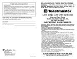
VARIMOT® Variable Speed Gear Unit
and Options
Edition
09/2000
Operating Instructions
0922 1115 / EN
SEW-EURODRIVE
1
Important Notes................................................................................................. 4
2
Safety Notes ...................................................................................................... 5
3
VARIMOT® Design ............................................................................................ 6
3.1 VARIMOT® variable speed gear unit – unit design................................... 6
3.2 Type designation....................................................................................... 6
3.3 Overview of VARIMOT® mounting options ............................................... 7
4
Installation ......................................................................................................... 8
4.1 Before you begin....................................................................................... 8
4.2 Preliminary work ....................................................................................... 8
4.3 Installation of VARIMOT® ......................................................................... 8
4.4 Mounting of output components................................................................ 9
5
Startup.............................................................................................................. 11
5.1 VARIMOT® startup ................................................................................. 11
6
Installation and Setup of Optional Equipment ............................................. 12
6.1 Connection and setup of EF/EFPA adjustment device .......................... 12
6.2 Installation, connection and setting of IG, FL and DA............................. 15
7
Inspection / Maintenance ............................................................................... 19
7.1 Inspection and maintenance intervals..................................................... 19
7.2 Before you begin..................................................................................... 19
7.3 Inspection / maintenance of VARIMOT® ................................................ 19
7.4 Lubricate EF/ EFPA adjusting spindle .................................................... 21
8
Operation and Service .................................................................................... 22
8.1 Malfunction of VARIMOT® variable speed gear unit............................... 22
8.2 Malfunction of optional equipment .......................................................... 23
I
0
"VARIMOT® Variable Speed Gear Unit " – Operating Instructions
3
1
Important Notes
1
Important Notes
Safety and
warning
instructions
Always follow warnings and safety instructions in this publication!
Electrical hazard
Possible effects: Serious or fatal injury.
Immediate danger
Possible effects: Serious or fatal injury.
Dangerous situation
Possible effects: Minor injury.
Harmful situation
Possible effects: Damage to equipment or surroundings.
Application hints and useful information.
Close adherence to these instructions is required for fault-free operation and fulfillment
of any warranty claims. Read these instructions carefully before you start operating the
drive!
These operating instructions contain vital servicing information and should be stored
close to the drive unit.
Disposal
(Please observe all applicable regulations):
• Housing components, gear wheels, shafts and rolling bearings of gear units should
be disposed of as steel scrap. This also applies to components made of cast iron if
no separate collection is available.
Revisions to edition 3/95 are indicated by a gray bar in the margin.
4
"VARIMOT® Variable Speed Gear Unit" – Operating Instructions
Safety Notes
2
2
Safety Notes
Preliminary
remarks
The following safety notes apply to variable speed gear units.
When using variable speed geared motors, please observe safety notes for gear units
and motors in the appropriate operating instructions.
Please refer to the additional safety notes in the individual sections of these
operating instructions.
General
All tasks related to transport, storage, installation/assembly, connection, startup,
service and maintenance may be performed by qualified technical personnel only
with strict adherence to:
• detailed operating instruction(s) and block diagrams
• warning and safety labels on the gear unit/geared motor
• system-specific regulations and requirements
• national/regional safety and accident prevention regulations
Serious personal injuries and material damage may occur through
• incorrect use
• improper installation or operation
• inadmissible removal of required protective covers or of the housing
Be aware that variable speed geared motors contain live and moving components and
hot surfaces during and after operation.
Intended usage
These variable speed geared motors/variable speed gear units are intended for
industrial systems. They comply with existing standards and regulations. The technical
data and information on approved operating conditions can be found on the nameplate
and in the documentation.
All details must be strictly observed!
Transport /
Storage
Inspect the shipment for damages upon receipt. Inform the shipping company
immediately of any damages. In case of damages, startup may have to be
cancelled.
Securely tighten lifting eyebolts. The eyebolts are specifically designed for the weight of
the geared motor/gear unit; no additional loads may be applied.
If necessary, use appropriate and sufficiently dimensioned handling equipment.
Remove existing shipping braces prior to startup.
"VARIMOT® Variable Speed Gear Unit" – Operating Instructions
5
VARIMOT® variable speed gear unit – unit design
3
3
VARIMOT® Design
3.1
VARIMOT® variable speed gear unit – unit design
1
9
8
7
3
10 6
5
4
50018AXX
Figure 1: VARIMOT® design
1
3
4
5
6
7
8
9
10
3.2
Output shaft, complete
Plate
Adjustable plate
Cover
Drive disc
Needle bearing
Housing
Hollow shaft, complete
Friction ring
Type designation
Example
DF 26 DT 90L 4 TF
Temperature sensor
Number of poles (motor)
Motor size
Motor series
®
VARIMOT variable speed gear unit size
®
VARIMOT variable speed gear unit series
Flange design
03829AEN
6
"VARIMOT® Variable Speed Gear Unit" – Operating Instructions
Overview of VARIMOT® mounting options
3.3
3
Overview of VARIMOT® mounting options
2
3
4
5
1
6
FL
DA
Figure 2: Overview of VARIMOT® mounting options
1
2
3
4
5
6
50032AXX
Adjustment device with free shaft end NV
Adjustment device with handwheel and position indication HS
Adjustment device with handwheel H (standard design)
Adjustment device with sprocket wheel K
Electromechanical remote adjustment EF and EFPA (with remote position indication)
Voltage pulse encoder IG with analog/digital remote speed display FL/DA
"VARIMOT® Variable Speed Gear Unit" – Operating Instructions
7
Before you begin
4
4
Installation
4.1
Before you begin
The drive may
only be installed
if
•
•
•
•
4.2
Preliminary work
Variable-speed
gear units
4.3
the entries on the nameplate of the drive match the supply voltage
the drive is not damaged (no damage resulting from transport or storage)
the following requirements have been properly fulfilled:
– ambient temperature between 0 °C and +40 °C,
– no oils, acids, gases, vapors, radiation, etc.
IP enclosure corresponds to ambient conditions
Output shafts and flange surfaces must be completely free of anti-corrosion agents,
contamination or other impurities (use a commercially available solvent). Do not let the
solvent come into contact with the sealing lips of the oil seals – damage to the material
may result!
Please note:
• The service life of the lubricant in the bearings is reduced if the unit is stored for
more than one (1) year.
Installation of VARIMOT®
•
•
Please note:
VARIMOT® design HS (handwheel with position indication) must be mounted so
that the adjusting spindle is horizontal; otherwise the position indication will not
function properly.
•
The breather valves must be easily accessible! The plastic plug of the
condensate drain hole at the lowest position must be removed prior to
operation (danger of corrosion!)
•
Carefully align the motor and driven machine to avoid overloading the motor shaft
(observe approved overhung loads and axial forces!).
Do not hammer or hit the shaft end.
•
Installation in
damp areas or in
the open
The variable speed geared motor may be mounted or installed only in the specified
position on a level1), vibration-free and torsionally rigid support structure. Do not
tighten housing legs and mounting flanges against each other.
•
Protect vertically mounted motors with an appropriate cover to protect
equipment from foreign bodies or fluids! (cowl C)
•
Ensure adequate supply of cooling air and that heated air from other units is not
drawn in.
VARIMOT® gear units are supplied in corrosion-resistant versions (design B) for
use in damp areas or in the open. Any paint damages must be repaired.
Coat the threads of screwed cable glands and sealing plugs with sealant, and
tighten well – apply another coat of sealant.
•
•
1) Maximum permitted flatness error for flange mounting (approximate value with reference
to DIN ISO 1101): with → flange 120 – 600 mm max. error 0.2 – 0.5 mm
8
"VARIMOT® Variable Speed Gear Unit" – Operating Instructions
Mounting of output components
•
•
4
Properly seal the cable entry.
Thoroughly clean the sealing surfaces of the terminal box and terminal box cover
before re-assembly. Replace porous seals!
Painting the gear
unit
If the drive will be painted or partially repainted, ensure that the breather valve and oil
seals are carefully covered with tape. Remove tape strips after the paint work is finished.
Required tools
•
•
•
Installation
tolerances
Wrench set
Mounting device
Mounting materials for output components
Shaft end
Flanges
Diametric tolerances in accordance with DIN 748
• ISO k6 for solid shafts with d, d1 ≤ 50 mm
• ISO k7 for solid shafts with d, d1 > 50 mm
• Center hole acc. to DIN 332, shape DR..
4.4
Centering shoulder tolerances acc. to DIN 42948
• ISO j6 at b1 ≤ 230 mm
• ISO h6 at b1> 230 mm
Mounting of output components
Figure 3 shows an example of a mounting device for mounting clutches or hubs onto
variable speed gear unit shaft ends. The thrust bearing on the mounting device may
become redundant.
Gear unit shaft end
Thrust bearing
Coupling hub
03371AEN
Figure 3: Example of a mounting device
"VARIMOT® Variable Speed Gear Unit" – Operating Instructions
9
Mounting of output components
4
Figure 4 shows the correct mounting arrangement b of a gear or sprocket wheel in
order to avoid excessive overhung loads.
a Hub
b
FX1
FX1
Hub
X1
X1
incorrect
correct
03369AEN
Figure 4: Correct mounting arrangement of a gear wheel or a sprocket wheel
•
Only use a mounting device (see Figure 3) for installing input and output elements.
Use the center bore and the thread on the shaft end for positioning purposes.
•
Never drive belt pulleys, clutches, pinions, etc. onto the shaft end by hitting
them with a hammer (damage to bearings, housing and the shaft!).
Please observe correct tension of the belt for belt pulleys (in accordance with
manufacturer’s specifications).
•
•
Mounted transmission elements should be balanced and may not cause any
unacceptable radial or axial forces (see Figure 4).
Note:
Assembly is easier if you first apply lubricant to the output element or heat it up briefly
(80–100 °C).
Installation of
clutches
While installing clutches, the following items must be balanced in accordance
with clutch manufacturer specifications:
a) Maximum and minimum clearance
b) Axial offset
c) Angular offset
a)
b)
c)
03356AXX
Figure 5
Input and output elements such as belt pulleys, clutches, etc. must be equipped
with a touchguard device!
10
"VARIMOT® Variable Speed Gear Unit" – Operating Instructions
VARIMOT® startup
5
Startup
5.1
VARIMOT® startup
5
Check the correct direction of rotation in the disengaged state (paying special attention
to unusual sliding noises during racing phase).
Secure key for operation of output components in trial run. Do not deactivate
monitoring and protection devices – not even for the trial run.
If in doubt, modifications to normal operation (e. g. increased temperature, noises,
vibrations) may require that the variable speed geared motor be switched off. Determine
the cause and contact SEW, if necessary.
"VARIMOT® Variable Speed Gear Unit" – Operating Instructions
11
Connection and setup of EF/EFPA adjustment device
6
6
Installation and Setup of Optional Equipment
Secure key for trial run without output components. Do not deactivate monitoring
and protection devices – not even for the trial run.
6.1
Connection and setup of EF/EFPA adjustment device
Electromechanical remote
speed adjustment
EF, EFPA
The electromechanical remote speed adjustment option consists of a variable speed
motor featuring a display unit in the EFPA version. This display unit may be installed in
a control cabinet. The display does not indicate speed changes due to load fluctuations.
Note:
The electromechanical remote speed adjustment option EF is designed for 40 % ED
and a switching rate of ≤ 20 times per hour. It is not suited for automatic control.
Connecting the
variable speed
motor EF, EFPA
1. Remove housing cover (1) from the
switch element of the variable speed
motor
2. Electrically connect the device
– according to the enclosed wiring
diagram
– in accordance with the information
on the nameplate
3. a) if desired, limit the speed range for
the variable speed motor EF (see
section "Limiting the speed range for
EF, EFPA" on page 13), otherwise
replace housing cover
b) for EFPA variable speed motor,
connect the display unit according
to the enclosed wiring diagram
(section "Connecting / adjusting
display unit for EFPA" on page 13)
1
02425AXX
Figure 6: Connecting variable speed motor EF, EFPA
12
"VARIMOT® Variable Speed Gear Unit" – Operating Instructions
Connection and setup of EF/EFPA adjustment device
Connecting /
adjusting display
unit for EFPA
6
The display unit for the electromechanical remote speed adjustment option can be used
only in conjunction with the EFPA variable speed geared motor.
1. Connect the unit according to the enclosed
wiring diagram
2. Adjust variable speed geared motor to
desired minimum speed
3. Adjust display unit via "MIN" setting screw:
– for D16 through D36 to 20 %
– for D46 to 25 %
4. Adjust variable speed geared motor to
desired maximum speed
5
6
7
SL
MIN
220V
MAX
– Adjust display unit via "MAX" setting
screw to 100 %
03854AXX
Figure 7: Location of setting screws on the display unit
Limiting the
speed range for
EF, EFPA
The operating cams for the limit switches are set in the factory so that the complete
speed range of the VARIMOT® variable speed geared motor is available. The range can
be limited as follows (Figure 8):
Limit the adjustment range only via limit switches – do not run motor to
mechanical stop (potential material damage)!
1. Remove housing cover (1) from switch
element of the variable speed motor
2. Adjust VARIMOT® to desired upper limit
position (scale ≤ 100 = maximum speed)
1
3. a) upper operating cam (3):
– loosen with screwdriver
– turn counterclockwise until tripping point
is reached
5
4
3
2
03811AXX
Figure 8: Position and detail view of setting cams
"VARIMOT® Variable Speed Gear Unit" – Operating Instructions
13
6
Connection and setup of EF/EFPA adjustment device
for design with potentiometer (5)
(Figure 9):
b) loosen lower screw of clutch (4)
c) turn potentiometer (5) on clutch
– counterclockwise until stop is reached
– clockwise by approx. 15 ° until 120 to 180 Ω are present on terminals 6 and 7
d) tighten lower screw of clutch (4)
4. tighten upper operating cam (3)
5. set VARIMOT® to desired lower limit position (scale ≥ 100 = minimum speed)
6. lower operating cam (2)
– loosen with screwdriver, turn clockwise until tripping point is reached
– tighten
7. install housing cover (1) (enclose wiring diagram)
1
5
4
3
2
03812AXX
Figure 9: Position and detail view of setting cams
14
"VARIMOT® Variable Speed Gear Unit" – Operating Instructions
Installation, connection and setting of IG, FL and DA
6.2
6
Installation, connection and setting of IG, FL and DA
Various designs
The following designs are possible:
1. IG:
– The scope of delivery for this design contains only the IG voltage pulse encoder
without FL or DA display unit.
2. FL:
– The scope of delivery for this design contains the IG voltage pulse encoder with
FL analog remote speed indication.
3. DA:
– The scope of delivery for this design contains the IG voltage pulse encoder with
DA digital remote speed indication.
4. IGV:
– This design includes an M16x1 thread for attaching a voltage pulse encoder to
the housing of the variable speed geared motor.
Installation of the
IG voltage pulse
encoder
The separate IG voltage pulse encoder is installed as follows:
1. Install voltage pulse encoder (30) into the appropriate thread of the geared motor
housing until it touches the pressure disc (31).
2. Turn back voltage pulse encoder (30) by two turns (clearance = 2 mm)
3. Secure voltage pulse encoder (31) with lock nut
4. If no display is present, correct input sensitivity:
– increase or decrease clearance between voltage pulse encoder and pressure
disc
30
31
2 mm
02415AXX
Figure 10: IG voltage pulse encoder
"VARIMOT® Variable Speed Gear Unit" – Operating Instructions
15
Installation, connection and setting of IG, FL and DA
6
Contact-free FL
analog remote
speed display
•
•
•
•
Connection/
adjustment of FL
The FL analog remote speed display is connected to the IG voltage pulse encoder at the
VARIMOT®.
IG voltage pulse encoder
Analog display unit (scale from 0 % to 100 %)
Supply voltage 230 V, 40-60 Hz
Encoder connection with two-core shielded cable
1. Connect the device
2. Operate drive at maximum speed
3. Adjust the unit via setting screws "GROB" (coarse) or "FEIN" (fine) (at the back of the
display unit) to a reading of 100 %
4. Ensure perfect ground connection at terminal M
1
Voltage pulse encoder (IG)
2
3
230 V M GBS S
GROB
FEIN
03709AEN
Figure 11: Connecting and adjusting FL analog remote speed display
16
"VARIMOT® Variable Speed Gear Unit" – Operating Instructions
Installation, connection and setting of IG, FL and DA
6
Contact-free DA
digital remote
speed display
•
•
•
•
•
Connection/
adjustment of DA
The DA digital remote speed display is connected to the IG voltage pulse encoder
(Figure 12 and Figure 13):
1. Connect the device (Figure 12)
2. Ensure perfect ground connection at terminal 1
3. Set measuring interval (Figure 13 and Section "DA calculation examples" on
page 18)
– Calculation using a formula
– Data in accordance with Table 1 on page 18
IG voltage pulse encoder
Digital display unit
Supply voltage 230 V, 50-60 Hz
Power consumption approx. 4.2 VA
Encoder connection with two-core cable, shielded
4. Adjust input sensitivity (Figure 13):
– Turn potentiometer "input sensitivity" clockwise until pulse indicator light starts to
glow
Voltage pulse encoder (IG)
1
2
3
1
1
2
Auxiliary voltage supply
1
2
3
4
5
230 V
jumper 8.9
6
7
8
9 10
115 V
jumper 7.9 and 8.10
03838AEN
Figure 12: Connecting the DA digital remote speed display
1
Time basis [s]
Pulse multiplier
0.1 0.01 0.001
x10
x1
Pulse control
Decimal point setting
Input sensitivity
03708AEN
Figure 13: Adjusting the DA digital remote speed display
"VARIMOT® Variable Speed Gear Unit" – Operating Instructions
17
Installation, connection and setting of IG, FL and DA
6
DA adjustment
information
•
•
•
•
•
Accuracy of indication:
+ / -1 of last digit
Measuring interval (quartz): adjustment in increments of 0.001 s in the range of
0.010 s to 9.999 s after removing the face plate,
recommended measuring interval: 0.5 to 2 s
Pulse multiplier:
adjustment in the range from 1 to 99 after removing
the face plate
Decimal point setting:
via DIP switch after removing the face plate
Calculation of measuring
interval:
60 ⋅ A Measuring interval = ----------------------n⋅k⋅z⋅f
A = 4-digit display (at maximum speed), without decimal indication
n = speed (Table 1 on page 18)
k = pulse multiplier ≥ 1
z = pulses / revolution (Table 1)
f = calculation factor (at 50 Hz = 1, at 60 Hz = 1.2)
Type / Size
VARIMOT®
VARIMOT® reference speed [rpm]
Pulses /
Revolution
2-pole
4-pole
6-pole
8-pole
3305
1690
1065
833
3520
1825
1200
885
D 36
3370
1675
1080
825
D 46
3240
1610
1073
850
D 16
D 26
6
Table 1: DA reference data
DA calculation examples
Example 1
Drive
R103R72D36DADV112M4
Data
Output speed
Pulses / revolution
(Table 1 on page 18)
Max. speed var. speed gear
(Table 1 on page 18)
Selected display
60 ⋅ A
------------------------n⋅k⋅z⋅f
Output speed
Example 2
R103R72D36DADVDV112M4
na = 1.5 – 7.5
z =6
n = 1675 rpm
A = 1.500 – 7.500 min-1
60 ⋅ 7500
------------------------------------ = 44, 78s
1675 ⋅ 1 ⋅ 6 ⋅ 1
Recommended
measuring interval
Output speed
na = 1.5 – 7.5
Pulses / revolution
z =6
(Table 1 on page 18)
Max. speed var. speed gear n = 1675 rpm
(Table 1 on page 18)
Belt speed
A = 0.5 . 2.5 m/min
60 ⋅ 2500
------------------------------------ = 14, 925s
1675 ⋅ 1 ⋅ 6 ⋅ 1
0.5 - 2 s (max. 9.999 s)
k = 50
k = 10
Calculation with
60 ⋅ 7500
60 ⋅ 2500
Measuring interval = ---------------------------------------- = 0, 896s
Measuring interval = ---------------------------------------- = 1, 493s
1675 ⋅ 50 ⋅ 6 ⋅ 1
1675 ⋅ 10 ⋅ 6 ⋅ 1
new pulse multiplier
Device setup
18
Measuring interval: [0] [8] [9] [6]
Pulse multiplier:
[5] [0]
Decimal point setting: 1
Measuring interval:
[1] [4] [9] [3]
Pulse multiplier:
[1] [0]
Decimal point setting: 1
"VARIMOT® Variable Speed Gear Unit" – Operating Instructions
Inspection and maintenance intervals
7
Inspection / Maintenance
7.1
Inspection and maintenance intervals
Unit / unit part
Interval
What to do?
-> Section
VARIMOT®
Every 3000 hours of operation
At least every six months
Check torsional play
(wear of friction ring)
see "Check torsional play" on page
19
Every 20 000 adjustments
At least every six months
Check adjusting spindle
• replace, if necessary
• otherwise lubricate
see "Lubricate EF/ EFPA adjusting
spindle" on page 21
EF, EFPA
7.2
7
Before you begin
Required tools
•
•
•
•
•
Wrench set
Hammer
Mandrel or drift punch
Hand lever press
Lubricant "Never Seeze normal"
Before opening the drive, the motor must be disconnected from the power supply
and protected from unintentional re-start!
7.3
Inspection / maintenance of VARIMOT®
Check torsional
play
The torsional play of the output shaft is increased through wear of the friction ring. The
torsional play can be checked as follows:
1. Remove fan cover of drive motor
2. Adjust output to speed ratio 1:1 (approximately value "80" on the scale of the
position indication)
3. Check torsional play at motor fan blade with fixed drive shaft
4. If torsional play measures > 45 °, the friction ring must be checked (see "Checking
the friction ring" on page 20)
"VARIMOT® Variable Speed Gear Unit" – Operating Instructions
19
7
Inspection / maintenance of VARIMOT®
Checking the
friction ring
1. Loosen all retaining screws (2)
2. Disconnect drive between housing cover and
housing
Friction ring profile
Wear height
3. Check friction ring
– if chamfers are visible: friction ring is OK
– if friction ring is damaged or chamfer is
ground off: replace friction ring
new
worn
03830AEN
Figure 14: Check friction ring
Replacing the
friction ring
1. Pull entire hollow shaft (9) from housing (8)
2. Remove friction ring (10) from hollow shaft
using hammer and mandrel or drift punch
2
1
9
3. Place new friction ring on a clean, level base
4. Place complete hollow shaft on friction ring
– pre-center via friction ring offset
5. Press hollow shaft and friction ring together
using slight pressure (if possible, use hand
lever press) until stop is reached
6. Lubricate needle bearing (7) with anti-friction
bearing grease
50020AXX
8
7
10
Figure 15: Checking/replacing friction ring
7. Clean bearing surface:
3 16
– friction ring – use dry paper or cloth
– drive disc (6) – use degreasing detergent
8. Push entire hollow shaft with friction ring into
the housing
– turn the hollow shaft during insertion until
cam lines are engaged (do not turn hollow
shaft any further)
9. Carefully join housing and housing cover and
tighten evenly
10. Check torsional play at output shaft
– correct: minor torsional play can be detected
11. Switch on varibale speed geared motor:
– slowly pass through the speed range
– correct: drive runs noise-free and
vibration-free
6
5
4
50019AXX
Figure 16: Checking/replacing friction ring
20
"VARIMOT® Variable Speed Gear Unit" – Operating Instructions
7
Lubricate EF/ EFPA adjusting spindle
7.4
Lubricate EF/ EFPA adjusting spindle
1. Remove variable speed motor (11) and intermediate flange (12)
2. Remove adjusting spindle (13) from drive by turning it clockwise
3. Lubricate adjusting spindle (4) with well-adhering lubricant, e. g. "Never Seeze
normal"
4. Install in reverse order
14
11
15
12
13
50021AXX
Figure 17: Lubricate EF/ EFPA adjusting spindle
"VARIMOT® Variable Speed Gear Unit" – Operating Instructions
21
Malfunction of VARIMOT® variable speed gear unit
8
8
Operation and Service
Please provide the following information if you require assistance from customer
service:
•
•
•
•
8.1
Nameplate information
State type and extent of the fault
Time and circumstances of the fault
Presumed cause
Malfunction of VARIMOT® variable speed gear unit
Malfunction
Possible cause
Friction ring is worn
Drive slips
Friction ring or face of adjustment
disc is contaminated
Replace friction ring (Section "Check torsional
play" on page 19)
Clean contaminated part.
• Friction ring – use dry paper or cloth
• Drive disc – use solvent or similar product
Load is too high
Check measured power and reduce to catalog
values
Drive warms up
excessively
Load is too high
see above
Note:
Housing
temperatures up to
70 °C are normal
Ambient temperature is too high or Reduce load based on ft factor in accordance
was not considered during
with the catalog
dimensioning
Drive is too loud
Friction ring is damaged
Note:
Damage can occur
• after brief stalling of the drive
• with intermittent loading of the
drive
Rated motor power is Speed range is too small
not transferred
22
Solution
1. Remedy cause
2. Replace friction ring (Section "Replacing the
friction ring" on page 20)
Increase speed range
"VARIMOT® Variable Speed Gear Unit" – Operating Instructions
Malfunction of optional equipment
8.2
8
Malfunction of optional equipment
Electromechanical remote speed
adjuster EF, EFPA
Malfunction
Adjustment rate
too low
Possible cause
Sluggish conduction (e. g. due to
corrosion) if B design is not used in
humid locations
Solution
Re-establish low-friction conduction
• Remove screws between housing and
housing cover
• Open drive
• Place drive vertically on fan cover
• Loosen screws under plastic cap next to
handwheel
• Pull pillar guides down and out of the drive
• Lubricate guide screws with well-adhering
lubricant, e. g. "Never Seeze normal"
Tip:
• First remove the pillar guides individually,
then lubricate and re-assemble them.
Speed cannot be
adjusted
Wire unit correctly in accordance with circuit
diagram
Speed range
Limit switches of variable speed
cannot be reached motor switch off too early
Adjust cams correctly for limit switch actuation
(Section "Limiting the speed range for EF,
EFPA" on page 13)
No display
Connect display unit correctly in accordance
with circuit diagram
Incorrect display
Contact-free
remote speed
display FL and
DA, voltage pulse
encoder IG
Unit is not wired properly
Malfunction
No display or
no signal
• Display unit is not properly
connected
• Voltage supply is missing or
interrupted
Display is not properly adjusted
Possible cause
Adjust display on back of unit (Section "Limiting
the speed range for EF, EFPA" on page 13)
Solution
Input sensitivity (clearance of pulse Correct input sensitivity:
encoder / screw head) too high or Increase or decrease clearance between IG
too low
voltage pulse encoder and screw head ( Section
"Various designs" on page 15)
• Unit is not properly connected
• Voltage supply is missing or
interrupted
"VARIMOT® Variable Speed Gear Unit" – Operating Instructions
Connect unit correctly in accordance with wiring
diagram
23
SEW Worldwide
SEW Worldwide
Germany
G
e
r
m
a
n
y
0
1
G
e
r
m
a
n
y
0
2
Headquarters
Production
Sales
Service
Production
Bruchsal
Graben
P.O. Box 3023 · D-76642 Bruchsal
Phone: (0 72 51) 75-0
Fax: (0 72 51) 75-19 70
Telex: 7 822 391
http://www.SEW-EURODRIVE.de
sew@sew-eurodrive.de
SEW-EURODRIVE GmbH & Co
Ernst-Blickle-Straße 1
D-76676 Graben-Neudorf
Phone: (0 72 51) 75-0
Fax: (0 72 51) 75-29 70
Telex: 7 822 276
SEW-EURODRIVE GmbH & Co
Ernst-Blickle-Straße 42
D-76646 Bruchsal
P.O. Box 1220 · D-76671 Graben-Neudorf
G
e
r
m
a
n
y
0
3
Assembly
Service
Garbsen
(near Hanover)
SEW-EURODRIVE GmbH & Co
Alte Ricklinger Straße 40-42
D-30823 Garbsen
Phone: (0 51 37) 87 98-30
Fax: (0 51 37) 87 98-55
P.O. Box 110453 · D-30804 Garbsen
G
e
r
m
a
n
y
0
4
Kirchheim
(near Munich)
SEW-EURODRIVE GmbH & Co
Domagkstraße 5
D-85551 Kirchheim
Phone: (0 89) 90 95 52-10
Fax: (0 89) 90 95 52-50
G
e
r
m
a
n
y
0
5
Langenfeld
(near Düsseldorf)
SEW-EURODRIVE GmbH & Co
Siemensstraße 1
D-40764 Langenfeld
Phone: (0 21 73) 85 07-30
Fax: (0 21 73) 85 07-55
G
e
r
m
a
n
y
0
6
Meerane
(near Zwickau)
SEW-EURODRIVE GmbH & Co
Dänkritzer Weg 1
D-08393 Meerane
Phone: (0 37 64) 76 06-0
Fax: (0 37 64) 76 06-30
G
e
r
m
a
n
y
0
7
Additional addresses for service in Germany provided on request!
France
Phone: 03 88 73 67 00
Fax: 03 88 73 66 00
http://www. USOCOME.com
sew@usocome.com
F
r
a
n
c
e
0
1
Production
Sales
Service
Haguenau
SEW-USOCOME SAS
48-54, route de Soufflenheim
B.P.185
F-67506 Haguenau Cedex
F
r
a
n
c
e
0
2
Production
Forbach
SEW-USOCOME SAS
Zone industrielle Technopole Forbach Sud
B. P. 30269
F-57604 Forbach Cedex
F
r
a
n
c
e
0
3
Assembly
Service
Technical Office
Bordeaux
SEW-USOCOME SAS
Parc d’activités de Magellan
62, avenue de Magellan - B. P.182
F-33607 Pessac Cedex
Phone: 05 57 26 39 00
Fax: 05 57 26 39 09
F
r
a
n
c
e
0
4
Lyon
SEW-USOCOME SAS
Parc d’Affaires Roosevelt
Rue Jacques Tati
F-69120 Vaulx en Velin
Phone: 04 72 15 37 00
Fax: 04 72 15 37 15
F
r
a
n
c
e
0
4
Paris
SEW-USOCOME SAS
Zone industrielle,
2, rue Denis Papin
F-77390 Verneuil I’Etang
Phone: 01 64 42 40 80
Fax: 01 64 42 40 88
F
r
a
n
c
e
0
5
Additional addresses for service in France provided on request!
08/2000
SEW Worldwide
Argentina
Buenos Aires
SEW EURODRIVE ARGENTINA S.A.
Centro Industrial Garin, Lote 35
Ruta Panamericana Km 37,5
1619 Garin
Phone: (3327) 45 72 84
Fax: (3327) 45 72 21
sewar@sew-eurodrive.com.ar
Melbourne
SEW-EURODRIVE PTY. LTD.
27 Beverage Drive
Tullamarine, Victoria 3043
Phone: (03) 99 33 10 00
Fax: (03) 99 33 10 03
Sydney
SEW-EURODRIVE PTY. LTD.
9, Sleigh Place, Wetherill Park
New South Wales, 2164
Phone: (02) 97 25 99 00
Fax: (02) 97 25 99 05
Vienna
SEW-EURODRIVE Ges.m.b.H.
Richard-Strauss-Strasse 24
A-1230 Wien
Phone: (01) 6 17 55 00-0
Fax: (01) 6 17 55 00-30
sew@sew-eurodrive.at
Bruxelles
CARON-VECTOR S.A.
Avenue Eiffel 5
B-1300 Wavre
Phone: (010) 23 13 11
Fax: (010) 2313 36
http://www.caron-vector.be
info@caron-vector.be
Sao Paulo
SEW DO BRASIL
Motores-Redutores Ltda.
Caixa Postal 201-0711-970
Rodovia Presidente Dutra km 213
CEP 07210-000 Guarulhos-SP
Phone: (011) 64 60-64 33
Fax: (011) 64 80-43 43
sew.brasil@originet.com.br
Sofia
BEVER-DRIVE GMBH
Bogdanovetz Str.1
BG-1606 Sofia
Phone: (92) 9 53 25 65
Fax: (92) 9 54 93 45
bever@mbox.infoPhone:bg
Toronto
SEW-EURODRIVE CO. OF CANADA LTD.
210 Walker Drive
Bramalea, Ontario L6T3W1
Phone: (905) 7 91-15 53
Fax: (905) 7 91-29 99
C
a
n
a
d
a
0
2
Vancouver
SEW-EURODRIVE CO. OF CANADA LTD.
7188 Honeyman Street
Delta. B.C. V4G 1 E2
Phone: (604) 9 46-55 35
Fax: (604) 946-2513
C
a
n
a
d
a
0
3
Montreal
SEW-EURODRIVE CO. OF CANADA LTD.
2555 Rue Leger Street
LaSalle, Quebec H8N 2V9
Phone: (514) 3 67-11 24
Fax: (514) 3 67-36 77
Santiago de Chile
SEW-EURODRIVE CHILE
Motores-Reductores LTDA.
Panamericana Norte No 9261
Casilla 23 - Correo Quilicura
RCH-Santiago de Chile
Phone: (02) 6 23 82 03+6 23 81 63
Fax: (02) 6 23 81 79
Tianjin
SEW-EURODRIVE (Tianjin) Co., Ltd.
No. 46, 7th Avenue, TEDA
Tianjin 300457
Phone: (022) 25 32 26 12
Fax: (022) 25 32 26 11
A
r
g
e
n
t
i
n
a
0
1
Assembly
Sales
Service
Australia
A
u
s
t
r
a
l
i
a
0
1
Assembly
Sales
Service
A
u
s
t
r
a
l
i
a
0
2
Austria
A
u
s
t
r
i
a
0
1
Assembly
Sales
Service
Belgium
B
e
l
g
i
u
m
0
1
Assembly
Sales
Service
Brazil
B
r
a
z
i
l
0
1
Production
Sales
Service
Bulgaria
B
u
l
g
a
r
i
a
0
1
Sales
Canada
C
a
n
a
d
a
0
1
Assembly
Sales
Service
Chile
C
h
i
l
e
0
1
Assembly
Sales
Service
China
C
h
i
n
a
0
1
Production
Assembly
Sales
Service
08/2000
SEW Worldwide
Colombia
C
o
l
o
m
b
i
a
0
1
Assembly
Sales
Service
Bogotá
SEW-EURODRIVE COLOMBIA LTDA.
Calle 22 No. 132-60
Bodega 6, Manzana B
Santafé de Bogotá
Phone: (0571) 5 47 50 50
Fax: (0571) 5 47 50 44
Zagreb
KOMPEKS d. o. o.
PIT Erdödy 4 II
HR 10 000 Zagreb
Phone: +385 14 61 31 58
Fax: +385 14 61 31 58
Prague
SEW-EURODRIVE S.R.O.
Business Centrum Praha
Luná 591
16000 Praha 6
Phone: 02/20 12 12 34 + 20 12 12 36
Fax: 02/20 12 12 37
sew@sew-eurodrive.cz
Copenhagen
SEW-EURODRIVEA/S
Geminivej 28-30, P.O. Box 100
DK-2670 Greve
Phone: 4395 8500
Fax: 4395 8509
Tallin
ALAS-KUUL AS
Paldiski mnt.125
EE 0006 Tallin
Phone: 6 59 32 30
Fax: 6 59 32 31
Lahti
SEW-EURODRIVE OY
Vesimäentie 4
FIN-15860 Hollola 2
Phone: (3) 589 300
Fax: (3) 780 6211
Athens
Christ. Boznos & Son S.A.
12, Mavromichali Street
P.O. Box 80136, GR-18545 Piraeus
Phone: 14 22 51 34-6 + 14 22 51 48-9
Fax: 1-4 22 51 59
Boznos@otenet.gr
Normanton
SEW-EURODRIVE Ltd.
Beckbridge Industrial Estate
P.O. Box No.1
GB-Normanton, West- Yorkshire WF6 1QR
Phone: 19 24 89 38 55
Fax: 19 24 89 37 02
Budapest
SEW-EURODRIVE Ges.m.b. H.
Hollósi Simon Hút 14
H-1126 Budapest
Phone: (01) 2 02 74 84
Fax: (01) 2 01 48 98
Hong Kong
SEW-EURODRIVE LTD.
Unit No. 801-806, 8th Floor
Hong Leong Industrial Complex
No. 4, Wang Kwong Road, Kowloon, Hong
Kong
Phone: 2-7 96 04 77 + 79 60 46 54
Fax: 2-7 95-91 29
sew@sewhk.com
Baroda
SEW-EURODRIVE India Private Limited
Plot NO. 4, Gidc
Por Ramangamdi · Baroda - 391 243
Gujarat
Phone: 0 265-83 10 86
Fax: 0 265-83 10 87
sewindia@wilnetonline.net
Dublin
Alperton Engineering Ltd.
48 Moyle Road
Dublin Industrial Estate
Glasnevin, Dublin 11
Phone: (01) 8 30 62 77
Fax: (01) 8 30 64 58
Croatia
C
r
o
a
t
i
a
0
1
Sales
Service
Czech Republic
C
z
e
c
h
Sales
R
e
p
u
b
l
i
c
0
1
Denmark
D
e
n
m
a
r
k
0
1
Assembly
Sales
Service
Estonia
E
s
t
o
n
i
a
0
1
Sales
Finland
F
i
n
l
a
n
d
0
1
Assembly
Sales
Service
Greece
G
r
e
e
c
e
0
1
Sales
Service
Great Britain
G
r
e
a
t
B
r
i
t
a
i
n
0
1
Assembly
Sales
Service
Hungary
H
u
n
g
a
r
y
0
1
Sales
Service
Hong Kong
H
o
n
g
K
o
n
g
0
1
Assembly
Sales
Service
India
I
n
d
i
a
0
1
Assembly
Sales
Service
Ireland
I
r
e
l
a
n
d
0
1
Sales
Service
08/2000
SEW Worldwide
Italy
I
t
a
l
y
0
1
Assembly
Sales
Service
Milan
SEW-EURODRIVE di R. Blickle & Co.s.a.s.
Via Bernini,14
I-20020 Solaro (Milano)
Phone: (02) 96 98 01
Fax: (02) 96 79 97 81
Toyoda-cho
SEW-EURODRIVE JAPAN CO., LTD
250-1, Shimoman-no,
Toyoda-cho, Iwata gun
Shizuoka prefecture, P.O. Box 438-0818
Phone: (0 53 83) 7 3811-13
Fax: (0 53 83) 7 3814
Ansan-City
SEW-EURODRIVE CO., LTD.
R 601-4, Banweol Industrial Estate
Unit 1048-4, Shingil-Dong
Ansan 425-120
Phone: (031) 4 92-80 51
Fax: (031) 4 92-80 56
Bruxelles
CARON-VECTOR S.A.
Avenue Eiffel 5
B-1300 Wavre
Phone: (010) 23 13 11
Fax: (010) 2313 36
http://www.caron-vector.be
info@caron-vector.be
Skopje
SGS-Skopje / Macedonia
Teodosij Sinactaski”
6691000 Skopje / Macedonia
Phone: (0991) 38 43 90
Fax: (0991) 38 43 90
Johore
SEW-EURODRIVE Sdn. Bhd.
95, Jalan Seroja 39
81100 Johore Bahru
Johore
Phone: (07) 3 54 57 07 + 3 54 94 09
Fax: (07) 3 5414 04
Rotterdam
VECTOR Aandrijftechniek B.V.
Industrieweg 175
NL-3044 AS Rotterdam
Postbus 10085
NL-3004AB Rotterdam
Phone: (010) 4 46 37 00
Fax: (010) 4 15 55 52
Auckland
SEW-EURODRIVE NEW ZEALAND LTD.
P.O. Box 58-428
82 Greenmount drive
East Tamaki Auckland
Phone: (09) 2 74 56 272 74 00 77
Fax: (09) 274 0165
sales@sew-eurodrive.co.nz
Christchurch
SEW-EURODRIVE NEW ZEALAND LTD.
10 Settlers Crescent, Ferrymead
Christchurch
Phone: (09) 3 84 62 51
Fax: (09) 3 84 64 55
sales@sew-eurodrive.co.nz
Moss
SEW-EURODRIVE A/S
Solgaard skog 71
N-1539 Moss
Phone: (69) 2410 20
Fax: (69) 2410 40
Lima
SEW DEL PERU MOTORES REDUCTORES
S.A.C.
Los Calderos # 120-124
Urbanizacion Industrial Vulcano, ATE, Lima
Phone: (511) 349-52 80
Fax: (511) 349-30 02
Lodz
SEW-EURODRIVE Polska Sp.z.o.o.
ul. Pojezierska 63
91-338 Lodz
Phone: (042) 6 16 22 00
Fax: (042) 6 16 22 10
sew@sew-eurodrive.pl
Japan
J
a
p
a
n
0
1
Assembly
Sales
Service
Korea
K
o
r
e
a
0
1
Assembly
Sales
Service
Luxembourg
L
u
x
e
m
b
o
u
r
g
0
1
Assembly
Sales
Service
Macedonia
M
a
c
e
d
o
n
i
a
0
1
Sales
Malaysia
M
a
l
a
y
s
i
a
0
1
Assembly
Sales
Service
Netherlands
N
e
t
h
e
r
l
a
n
d
s
0
1
Assembly
Sales
Service
New Zealand
N
e
w
Z
e
a
l
a
n
d
0
1
Assembly
Sales
Service
N
e
w
Z
e
a
l
a
n
d
0
2
Norway
N
o
r
w
a
y
0
1
Assembly
Sales
Service
Peru
P
e
r
u
0
1
Assembly
Sales
Service
Poland
P
o
l
a
n
d
0
1
Sales
08/2000
SEW Worldwide
Portugal
P
o
r
t
u
g
a
l
0
1
Assembly
Sales
Service
Coimbra
SEW-EURODRIVE, LDA.
Apartado 15
P-3050-901 Mealhada
Phone: (0231) 20 96 70
Fax: (0231) 20 36 85
infosew@sew-eurodrive.pt
Bucharest
Sialco Trading SRL
str. Madrid nr.4
71222 Bucuresti
Phone: (01) 2 30 13 28
Fax: (01) 2 30 71 70
sialco@mediasat.ro
St. Petersburg
ZAO SEW-EURODRIVE
P.O. Box 193
193015 St. Petersburg
Phone: (812) 3 26 09 41 + 5 35 04 30
Fax: (812) 5 35 22 87
sewrus@post.spbnit.ru
Singapore
SEW-EURODRIVE PTE. LTD.
No 9, Tuas Drive 2
Jurong Industrial Estate
Singapore 638644
Jurong Point Post Office
P.O. Box 813
Singapore 91 64 28
Phone: 8 62 17 01-705
Fax: 8 61 28 27
Telex: 38 659
Johannesburg
SEW-EURODRIVE (PROPRIETARY) LIMITED
Eurodrive House
Cnr. Adcock Ingram and Aerodrome Roads
Aeroton Ext. 2
Johannesburg 2013
P.O. Box 27032
2011 Benrose, Johannesburg
Phone: (11) 49 44 380
Fax: (11) 49 42 300
Capetown
SEW-EURODRIVE (PROPRIETARY) LIMITED
Rainbow Park
Cnr. Racecourse & Omuramba Road
Montague Gardens, 7441 Cape Town
P.O.Box 53 573
Racecourse Park, 7441 Cape Town
Phone: (021) 5 11 09 87
Fax: (021) 5 11 44 58
Telex: 576 062
Durban
SEW-EURODRIVE (PROPRIETARY) LIMITED
39 Circuit Road
Westmead, Pinetown
P.O. Box 10433, Ashwood 3605
Phone: (031) 700 34 51
Telex: 622 407
Bilbao
SEW-EURODRIVE ESPAÑA, S.L.
Parque Tecnologico, Edificio, 302
E-48170 Zamudio (Vizcaya)
Phone: 9 44 31 84 70
Fax: 9 44 31 84 71
sew.spain@sew-eurodrive.es
Jönköping
SEW-EURODRIVE AB
Gnejsvägen 6-8
S-55303 Jönköping
Box 3100 S-55003 Jönköping
Phone: (036) 34 42 00
Fax: (036) 34 42 80
www.sew-eurodrive.se
Basel
Alfred lmhof A.G.
Jurastrasse 10
CH-4142 Münchenstein near Basel
Phone: (061) 4 17 17 17
Fax: (061) 4 17 17 00
http://www.imhof-sew.ch
info@imhof-sew.ch
Chon Buri
SEW-EURODRIVE (Thailand) Ltd.
Bangpakong Industrial Park 2
700/456, M007, Tambol Bonhuaroh
Muang District
Chon Buri 20000
Phone: 0066-38 21 45 29/30
Fax: 0066-38 21 45 31
Romania
R
o
m
a
n
i
a
0
1
Sales
Service
Russia
R
u
s
s
i
a
0
1
Sales
Singapore
S
i
n
g
a
p
o
r
e
0
1
Assembly
Sales
Service
South Africa
S
o
u
t
h
A
f
r
i
c
a
0
1
Assembly
Sales
Service
S
o
u
t
h
A
f
r
i
c
a
0
2
S
o
u
t
h
A
f
r
i
c
a
0
3
Spain
S
p
a
i
n
0
1
Assembly
Sales
Service
Sweden
S
w
e
d
e
n
0
1
Assembly
Sales
Service
Switzerland
S
w
i
t
z
e
r
l
a
n
d
0
1
Assembly
Sales
Service
Thailand
T
h
a
i
l
a
n
d
0
1
Assembly
Sales
Service
08/2000
SEW Worldwide
Turkey
T
u
r
k
e
y
0
1
Assembly
Sales
Service
Istanbul
SEW-EURODRIVE
Hareket Sistemleri San. ve Tic. Ltd. Sti
Bagdat Cad. Koruma Cikmazi No. 3
TR-81540 Maltepe ISTANBUL
Phone: (0216) 4 41 91 63 + 4 41 91 64
+ 3 83 80 14 + 3 83 80 15
Fax: (0216) 3 05 58 67
seweurodrive@superonline.com.tr
Uruguay
Please contact our office in Argentina.
U
r
u
g
u
a
y
0
1
USA
U
S
A
0
1
Production
Assembly
Sales
Service
Greenville
SEW-EURODRIVE INC.
1295 Old Spartanburg Highway
P.O. Box 518
Lyman, S.C. 29365
Phone: (864) 4 39 75 37
Fax: Sales (864) 439-78 30
Fax: Manuf. (864) 4 39-99 48
Fax: Ass. (864) 4 39-05 66
Telex: 805 550
U
S
A
0
2
Assembly
Sales
Service
San Francisco
SEW-EURODRIVE INC.
30599 San Antonio Road
P.O. Box 3910
Hayward, California 94544
Phone: (510) 4 87-35 60
Fax: (510) 4 87-63 81
U
S
A
0
3
Philadelphia/PA
SEW-EURODRIVE INC.
Pureland Ind. Complex
200 High Hill Road, P.O. Box 481
Bridgeport, New Jersey 08014
Phone: (856) 4 67-22 77
Fax: (856) 8 45-31 79
U
S
A
0
4
Dayton
SEW-EURODRIVE INC.
2001 West Main Street
Troy, Ohio 45373
Phone: (9 37) 3 35-00 36
Fax: (9 37) 4 40-37 99
U
S
A
0
5
Dallas
SEW-EURODRIVE INC.
3950 Platinum Way
Dallas, Texas 75237
Phone: (214) 3 30-48 24
Fax: (214) 3 30-47 24
U
S
A
0
6
Additional addresses for service in the USA provided on request!
Venezuela
V
e
n
e
z
u
e
l
a
0
1
Assembly
Sales
Service
Valencia
SEW-EURODRIVE Venezuela S.A.
Av. Norte Sur No. 3, Galpon 84-319
Zona Industrial Municipal Norte
Valencia
Phone: (041) 32 95 83 + 32 98 04 + 32
94 51
Fax: (041) 32 62 75
sewventas@cantr.net
sewfinanzas@cantr.net
08/2000
Notes
09/2000
Notes
09/2000
Notes
09/2000
SEW-EURODRIVE GmbH & Co · P.O.Box 30 23 · D-76642 Bruchsal/Germany · Tel. +49- 72 51-75-0
Fax +49-72 51-75-19 70 · http://www.SEW-EURODRIVE.com · sew @ sew-eurodrive.com