1
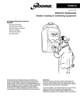
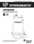
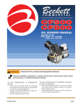
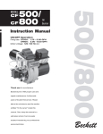
SERVICE
Service on fuel units should not be attempted without the aid of good vacuum and
pressure gages. Many system problems can be detected with the aid of these gages.
Service falls into two categories: routine and trouble.
ROUTINE · ANNUAL OR OTHER CHECK OUT
Check line filter and pump strainer for amount of contaminate. If close to needing
service, replace to prevent a call-back in near future. If using inlet into the side of the
pump, it isn’t necessary to remove cover to check the strainer. Remove inlet line and
view strainer through inlet opening. If it’s clean there, it will be clean the rest of the way
around.
If strainer is plugged, remove cover and clean strainer with a brush and clean fuel.
Replace cover gasket before reinstalling.
System running vacuum should be checked as part of routine.
Running vacuum should not exceed:
9 6 inches mercury for single-stage one-pipe.
9 12 inches mercury for single-stage two-pipe.
9 17 inches mercury for two-stage two-pipe.
9 Check and adjust system pressure, if necessary.
9 Check CO2 or O2 and system draft.
9 Check for smoke and adjust to a trace. Zero smoke is unclear as to where you are
in adjustment.
9 Check for leaks at fittings and filters. Correct any leaks that are found.
TROUBLE CALL
In response to a trouble call, approach the problem in a logical and systematic
sequence. Jumping to a conclusion can sometimes temporarily fix the problem, but not
uncover the root cause of the problem. An example is if there is water in the fuel, which
causes the pump to fail and you replace the pump only, you will eventually be called
back to replace the new pump.
In addition to the mechanical tools required, you also must have gages (pressure and
vacuum) and suitable combustion analyzers.
IV-1
SYSTEM TROUBLESHOOTING • DIAGNOSTIC FLOW CHART
Follow a logical equence of troubleshooting from the no-heat call through to system operational using the following chart or
similar sequence.
Step
1
p No heat
2
Yes p Check for oil in tank
No p Have oil delivered
3
Yes p Check to see that all valves are properly
positioned (open or closed)
No p Set valves to correct position
4
Yes p Check for line voltage at primary control
No p Check and correct electrical supply
5
Yes p Check to see that thermostat is calling
for heat
No p Set, fix or replace thermostat
6
Yes p Check combustion chamber for excess
oil
Yes p Clean, remove or replace
combustion chamber
7
No p Disconnect nozzle line from burner.
Place container under nozzle line and
start burner.
8
Yes p Motor comes up to speed. Audible click
when start windings drop out.
9
Yes p Ignition working
10
Yes p Steady stream of oil from pump
If rust or bacteria in pump, fuel tank No or p Replace Pump
has water in it and need attention:
Yes
Yes ~
No p Check for seized pump
No p Repair or replace ignition system
No p Check for clogged strainer (in
pump) or filter (external)
IV-2
No p Repair or replace motor and/or
primary control
Replace pump
No ~
No p Check vacuum capability of
pump (Technical Bulleting #223)
Yes
SYSTEM TROUBLESHOOTING · DIAGNOSTIC FLOW CHART (cont’d.)
Step
11
Yes p Install pressure gage in pump nozzle
port
12
Yes p Start burner, check and set correct pump
pressure
No p Replace pump
13
Yes p Stop burner and check that pressure
drops and stops at some positive value.
No p Replace pump
14
Yes p Reconnect nozzle line and test fire
burner
No p Check for nozzle problem
Repeat step #7
No
Check for ignition problem
No
Check combustion air supply
problem
No
q No Check for contaminated fuel
15
16
Yes
Yes p Set CO2 and smoke levels
No p Check system for blockages and
air leaks
Yes p Allow system to complete several cycles
IV-3
Yes
q Check inlet for air leak high
vacuum. Correct inlet line.
Yes p Replace nozzle
Yes p Repair or replace ignition
system
Yes p Reset to proper settings
Yes p Have tank pumped and refilled
FUEL PUMP · TROUBLESHOOTING GUIDE
CAUSE
REMEDY
NO OIL FLOW AT NOZZLE
Oil level below intake line in supply
tank..................................................
Fill tank with oil.
Clogged strainer or filter ................
Remove and clean strainer.
Replace filter element.
Clogged Nozzle ..............................
Replace nozzle.
Air leak in intake line .......................
Tighten all fittings in intake line.
Tighten unused intake port plug.
Check filter cover and gasket.
Restricted intake line
(high vacuum reading) ....................
A two-pipe system that
becomes airbound ..........................
A single-pipe system that
become airbound ............................
Slipping or broken coupling ............
Rotation of motor and fuel unit is
not the same as indicated by arrow
on pad at top of unit ........................
Frozen pump shaft ..........................
Replace any kinked tubing and
check any valves in intake line.
Check form 440100 for line sizes.
Check for and insert by-pass plug.
Make sure return line is below oil level in tank.
Loosen gage port plug or easy-flow valve and
bleed oil for 15 seconds after foam is gone in
bleed hose. Check intake line fittings for
tightness. Check all pump plugs for tightness.
Tighten or replace coupling.
Install fuel unit with correct rotation. See form
no. 440100.
Return unit to approved service station or
Suntec factory for repair. Check for water and
dirt in tank.
IV-4
FUEL PUMP · TROUBLESHOOTING GUIDE
CAUSE
REMEDY
OIL LEAK
Loose plugs or fittings .....................
Leak at pressure adj. screw or
nozzle plug ......................................
Blown seal
(single-pipe system) ........................
Dope with good quality thread sealer.
Retighten.
Washer may be damaged.
Replace with washer or o-ring.
Check to see if by-pass plug has been left in
unit. Replace fuel unit.
Blown seal
(two-pipe system) ............................ Check for kinked tubing or other obstructions in
return line. Replace fuel unit.
Seal leaking ....................................
Replace fuel unit.
Cover ..............................................
Tighten cover screws or replace damaged
gasket.
NOISY OPERATION
Bad coupling alignment ..................
Loosen fuel unit mounting screws slightly and
shift fuel unit in different positions until noise is
eliminated. Retighten mounting screws.
Air in inlet line .................................
Check all connections. Use only good flare
fittings.
Tank hum on two-pipe system and
inside tank .......................................
Install return line hum eliminator in return line.
PULSATING PRESSURE
Partially clogged strainer or filter ....
Remove and clean strainer. Replace filter
element.
Air leak in intake line .......................
Tighten all fittings.
Air leaking around cover .................
Be sure strainer cover screws are tightened
securely. Check for damaged cover gasket.
IV-5
FUEL PUMP · TROUBLESHOOTING GUIDE
CAUSE
REMEDY
LOW OIL PRESSURE
Defective gage ................................
Nozzle capacity is greater than fuel
unit capacity ....................................
Check gage against master gage or other gage.
Replace fuel unit with unit of correct capacity.
See form no. 2100 for GPH, psi, and R.P.M.
IMPROPER NOZZLE CUT-OFF
To determine the cause of improper cut-off, insert a pressure gage in the nozzle port of
the fuel unit. After a minute of operation, shut burner down. If the pressure drops from
normal operating pressure and stabilizes, the fuel unit is operating properly and air is
the cause of improper cut-off. If, however, the pressure drops to 0 psi, fuel unit should
be replaced.
NOTE: The A-70 pump circuitry is designed to give a high cut-off of superb quality.
Never use the amount of pressure drop as an indication of the quality or speed of
cut-off.
Filter leaks ......................................
Check face of cover and gasket for damage.
Strainer cover loose ........................
Tighten four screws on cover.
Air pocket between cut-off valve
and nozzle ......................................
Run burner, stopping and starting unit, until
smoke and after-fire disappears.
Air leak in intake line .......................
Tighten intake fittings. Tighten unused intake
port and return plug.
Partially-clogged nozzle strainer .....
Clean strainer or change nozzle.
Leak at nozzle adaptor ...................
Change nozzle and adaptor.
IV-6
FIELD TESTING FUEL UNITS
INTRODUCTION
Fuel units are sized to an application based on their pressure, vacuum, and flow ratings.
With today’s high efficiency furnaces and boilers, it is extremely important to check
these parameters when the initial installation is made and also during later service calls
to assure that high efficiency operation is being maintained.
It is also important to check fuel unit pressure and vacuum levels during trouble calls to
help differentiate pump problems from system problems.
VACUUM TEST • FOR FUEL UNITS AND INLET LINES
FIGURE 1 VACUUM GAGE LOCATION FOR SINGLE-PIPE SYSTEM
IV-7
Step 1. Remove inlet line from fuel unit and install vacuum gage in the inlet port (see
Figure 1). If unit has been running dry, pour oil into pump prior to testing.
Step 2. Turn burner ON and open bleed.
Step 3. When vacuum reaches 15 in. hg.*, close bleed port.
Step 4. Turn burner OFF. Pump should hold vacuum level for five minutes*.
*NOTE: If fuel unit cannot attain 15 in. hg. or hold that vacuum level for five minutes, it
should be repaired or replaced.
FIGURE 2 VACUUM GAGE LOCATION FOR TWO-PIPE SYSTEM
Step 1. Remove inlet line from fuel unit and install vacuum gage in the inlet port (see
Figure 2).
Step 2. Remove return line.
IV-8
Step 3.
Step 4.
Step 5.
Turn burner ON.
When vacuum reaches 15 in. hg.*, plug return port and turn burner OFF.
Pump should hold vacuum level for five minutes*.
*NOTE: If fuel unit cannot attain 15 in. hg. or hold that vacuum level for five minutes, it
should be repaired or replaced.
VACUUM TEST • FOR SYSTEM
FIGURE 3 VACUUM GAGE LOCATION FOR SYSTEM TEST
Step 1.
Install vacuum gage in the optional inlet port or tee into the supply line at the
fuel unit. (If the optional inlet is used for the supply line, install the gage in the
cover inlet. See Figure 3.)
Step 2. Turn burner ON and bleed the fuel unit (if one-pipe system).
Step 3. Close bleed valve and read gage. Readings should be as follows:
IV-9
Single-Pipe System
Two-Pipe System
SINGLE-STAGE
Model A
Model J
6 in. hg.
2 in. hg.
12 in. hg.
12 in. hg.
TWO-STAGE
Model B
Model H
6 in. hg.
2 in. hg.
17 in. hg.
17 in. hg.
Step 4. If the gage reading exceeds the level indicated for the fuel unit being used,
check the piping and the system layout (refer to Suntec installation bulletins*
for details).
Step 5. If the lift and run is not excessive for the fuel unit model, the problem could
be caused by
a. the number and type of bends in the piping (includes kinks and flattening),
b. the number and types of fittings in the piping,
c. the number, type, and condition of filters and strainers
d. the number and type of valves in the system, and/or
e. the level of contaminate build-up on the inside walls of the system piping.
Step 6. If the vacuum level is NOT excessive, and there is air in the oil, there is
usually a leak in the piping.
To check:
a. Close the tank valve,
b. Pull a vacuum on the system by the fuel unit,
c. Shut the burner OFF. System should hold the vacuum level for five minutes.
If system is two-pipe, the return line will have to be closed off at shutdown.
PRESSURE TEST • FOR FUEL UNITS AND SYSTEMS
SYSTEM PRESSURE WITH SYSTEM OPERATING
Step 1. If fuel unit is on a positive head system, shut tank valve OFF before installing
gage.
Step 2. Install gage in gage port.
Step 3. Turn burner ON if pump is on single-pipe lift system, bleed pump at the bleed
valve.
Step 4. Observe gage (disregard needle “jiggling”).
Step 5. If reading is high or low, readjust pressure adjustment screw.
NOTE: On Model J or Model H fuel units, there may be some leakage with the
acorn nut removed. This will stop when the nut is replaced.
Step 6. Turn burner OFF. The pressure should fall to zero or to the amount of head on
the fuel unit.
IV-10
FIGURE 4 PRESSURE GAGE LOCATIONS FOR OPERATING PRESSURE TEST
FUEL UNIT OPERATING AND CUT-OFF PRESSURE
Step 1.
Step 2.
Step 3.
Step 4.
Step 5.
Install gage into nozzle port.
Turn burner ON and observe gage.
Adjust pressure, if necessary.
Turn burner OFF and observe gage. Pressure should drop to 80% or higher.
If pressure drops below 80% or continues to decay, the fuel unit has faulty
cut-off and should be repaired or replaced.
NOTE: A and B model pumps could theoretically have a cut-off pressure of less than
80%. The important operation is that it drops to some value and stops.
IV-11
STRAINERS - FIELD SERVICE
Fuel unit strainers are intended as a back-up to, not a replacement for, proper system
filtering.
Clogged strainers restrict oil flow into the gear set, cause fuel units to operate at higher
vacuum and eventually fail. To diagnose a clogged strainer before it causes fuel unit
failure, it must be removed and visually inspected. If a strainer looks clogged, it usually
is, and should be cleaned or replaced.
IMPORTANT NOTE: Current regulations on the use of asbestos in gasket
materials require that new non-asbestos gaskets be installed any time a fuel unit
cover is removed. Make this a common practice to avoid expensive call-backs for
that purpose.
STRAINER IDENTIFICATION
MODEL J AND MODEL H FUEL UNITS
Strainer models are designed by the first character following the gear size designation
in the fuel unit model number, as indicated below:
Examples:
J3PBN-C200H-4
JA2BA-100
Strainer Model
Designation
A
B
C
N
P
K
“P” Strainer
“B” Strainer
Nozzle Capacity Rating
No strainer (used in certain lube pumps)
7 gph (metal frame)
4.5 gph (obsolete, use B or N)
7 gph (plastic frame)
Unlimited (do not use in Models J7, J8, H7, H8)
Unlimited (requires spacer between pump body and cover)
MODEL A AND MODEL B FUEL UNITS
Strainer models are designated by the first character following the gear size designation
in the fuel unit model number, as indicated below:
Examples:
A2VA-7116-4
B2TA-8851-5
“V” Strainer
“T” Strainer
IV-12
Strainer Model Designation
V
Y
T
G
Nozzle Capacity Rating
3 gph
7 gph
16 gph
23 gph
IMPORTANT - DO NOT use a strainer which is too long for the cover (indicated by
a 1/8” or more cover gap when spring is fully-compressed). Forcing would crush
the strainer body and allow contaminants to get into the pumping mechanism.
STRAINERS AS A DIAGNOSTIC INDICATOR
What you see in a strainer can be an indicator of what conditions may exist within the
system:
a. Clogged strainer. Primary filter has failed or is missing.
b. Sludge on strainer. Water in the tank, allowing biological growth.
c. Rust flakes on strainer. Rusted tank or components.
Field replacement of 3 gph- and 7 gph-rated strainers - Figure 1. (All models and
revisions of Model A70 and model B80 fuel units.)
To simplify field replacement and improve overall strainer efficiency, only two strainer
models are offered for replacement in standard Model A and Model B fuel units. As
shown, a spring is required in some instances to compensate for the difference in
strainer height and cover depth (see Figure 1).
Model
Series
A
A
A
B
B
B
B
Capacit
Model
Date
y
Revision*
Code
(GPH)
V
3
All
All
Y
7
Y82 & Earlier
Y
7
D82 & Later
V&Y
3&7
-2, -3, -4
All
V&Y
3&7
-5
All
T
16
All
All
G
23
All
All
* Model Revision = last number of model number
Strainer
Designation
Cover
Depth
Strainer
Part No.
1.133” 3715732
Not Req.
1.345” 3715732 3773231/3754732
1.620” 3715744
Not Req.
1.345” 3715732 3773231/3754732
1.620” 3715744
Not Req.
1.620” 3715742
Not Req.
1.620” 3715746
Not Req.
EXAMPLE: B2VA-8216-5
FIGURE 1 STRAINER REPLACEMENT
IV-13
Spring
Part No.
Installation of strainer part no. 3715732 in medium-height covers*
FIGURE 2 STRAINER INSTALLATION
Step 1.
Step 2.
Step 3.
Step 4.
Set spring (part no. 3773231 or 3754732) in cover with large coils up.
Set strainer (part no. 3715732) on large coil.
Install new gasket.
Slide cover over gearset.
IV-14
FILTERS AND FILTRATION
Filters are necessary in all fuel systems to capture contaminants which might develop
and create operational problems. They are the first line of defense, while the strainers
within a fuel unit serve as a secondary or back-up filter.
Contaminants come in many varieties:
a. Abrasive. Accelerate wear on moving parts.
b. Blocking. Clog filters, strainers, and oil passages.
c. Corrosive. Chemically attack metal elements.
d. Biological. Cause all of the above.
Relative contaminant size:
a. Smallest particle visible to the human eye = 40 microns.
b. Bacteria = 2 microns
c. 1 micron = .000039 inch.
d. 100-mesh screen opening = .0059 inch = 149 microns.
Contamination notes:
a. If filters require changing more than once a year, the filter is too small or the fuel
system is too dirty.
b. If the fuel system is dirty, it should be pumped out, treated and refilled with clean oil.
c. If moisture is present, it can rust the fuel system and parts, and provide a breeding
ground for bacteria.
d. If the fuel tank is treated with a bacticide, use only the recommended amount. Too
heavy a concentration can cause the fuel unit to become inoperative.
e. When replacing filter elements, care should be taken to not introduce the
contaminant downstream to the fuel unit.
f. If a filter element has collapsed, the fuel unit and lines must be flushed prior to
resuming burner operation.
g. If filter has a screen in it, make sure it is non-corroding material. Some are, and
some are not.
Field notes:
a. Some filter elements will cause outgassing of fuel oil at low flows and relatively low
vacuums (1 - 2 in. hg.). This usually appears as a loss of prime on one-pipe
installations. A field-cure for this is to shut off the tank valve while priming the pump
and put as much vacuum as possible on filter. Open the tank valve and resume
normal priming.
b. When changing filters, take care not to introduce contaminate from dirty element into
down-stream piping and fuel pump.
c. High vacuums across a filter element that appears to be clean can be caused by
greasy bridging-type contaminant.
IV-15
SOLENOID VALVES - SERVICE
INSTALLATION
Model R valves mount directly into the nozzle port of the fuel unit.
Model C valves mount to the burner chassis or otherwise remote from the fuel unit.
OPERATIONAL CHECK
Step 1. Remove nozzle line at the burner assembly end and place into container (to
catch oil).
Step 2. Start burner and watch for oil to run from the open line. If YES, go to Step 9. If
NO, go to Step 3.
Step 3. Turn burner OFF.
Step 4. Check for power to the coil. If YES, go to Step 5. If NO, repair electrical supply
and recheck.
Step 5. Remove nut which holds the coil into the valve asembly.
Step 6. Remove coil from valve and slide it over an insulated handle screwdriver.
IMPORTANT: to apply power to the coil without a screwdriver (or other
magnetic material) in the center hole will cause the coil to overheat, swell and
fail.
CAUTION: Even though the coil is fully-insulated, care should be exercised to
avoid touching the coil when energized, except with insulated tools.
Step 7. Apply power to the coil. You should feel vibrations and/or magnetic pull on the
screwdriver. If YES, go to Step 8. If NO, replace coil and go to Step 2.
Step 8. Replace tube assembly or complete valve assembly.
Step 9. Remove power from coil and start burner. Check to see if oil is passing through
the valve. If YES, replace tube assembly or valve assembly and go to Step 1.
If NO, valve is performing satisfactorily.
IV-16
Item No.
Description`
1
2
Coil Nut
Coil for:
R642N
R641D
R753
C642N
C641D
C753
Base plate screw (2)
Base plate
Tube assembly
“O” ring
Valve body
Gasket (2)
Nozzle screw
Electrical connector
Electrical connector
Electrical connector
3
4
5
6
7
8
9
10
11
12
IV-17
Part Order Number
“R” Valve
“C” Valve
3753818
3753818
3713642
3713809
3713790
3773421
3753762
3713766
3773461
3723810
2779261
3753835
-
3713642
3713809
3713790
3773421
3753864
3713766
3773461
3723815
3753865
-