1
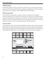
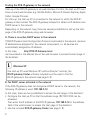
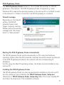
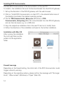
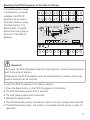
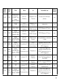
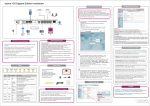
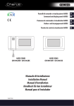
Operating Instructions
DCS-IP-gateway
2620 97, 2620 98, 2620 99
Contents
Device description ........................................................................................................ 4
Connection terminals .................................................................................................... 5
Installation .................................................................................................................... 6
Start-up ......................................................................................................................... 7
Finding the DCS-IP-gateway in the network ................................................................ 8
DCS-IP-gateway Finder ................................................................................................ 9
Gira Assistant .............................................................................................................. 11
Possibility for teleservicing ......................................................................................... 13
Installing DCS Communicator .................................................................................... 14
Audio Assistant ........................................................................................................... 15
DCS Communicator .................................................................................................... 16
Resetting the DCS-IP-gateway to the state of delivery ............................................... 17
Technical data ............................................................................................................. 18
LED display ................................................................................................................. 19
Appendix ..................................................................................................................... 20
Warranty ..................................................................................................................... 22
3
Device description
DCS-IP-gateway
The DCS-IP-gateway converts signals from the Gira door communication system to
the network protocol level (IP) and thus enables the integration of network-capable
devices such as computers, video-IP telephones and IP cameras.
DCS Communicator
With the DCS Communicator software, common computers and PC-based
operating devices such as the Gira Control 9 Client or Gira Control 19 Client can be
used as home stations via the network connection. The DCS Communicator offers
all the functions of a video home station such as accepting conversations, switching
lights (in conjunction with a switching actuator) and opening doors.
License models
Several license models are available for the DCS-IP-gateway. The number of licenses
determines how many devices (e.g. DCS Communicator, IP telephone, HomeServer
plug-in) may be logged onto the DCS-IP-gateway simultaneously. It should be noted
that the DCS Communicator can be installed on as many user PCs as desired.
4
Connection terminals
BUS IN
Connection for the incoming video signal from door stations with a video function
or camera gateways on the Gira 2-wire bus.
Because the video signal in the DCS-IP-gateway is only routed in one direction, from
BUS IN to BUS OUT, all door stations with a video function or camera gateways
must be connected to BUS IN.
BUS OUT
Connection of the DCS-IP-gateway to the video control device as well as all other
door communication devices such as door stations with an audio function, home
stations, VideoTerminals or switching actuators via the Gira 2-wire bus.
Ub
Connection for the power supply 24 V DC (neutral).
LAN
Link this connection to the router or switch using a network cable to maintain
access to the network.
Bus
3
1
Door stations with
camera, DCS-cameragateway
2
3
IN
Bus
4
5
4
5
OUT
Ub
LAN
6
7
8
6
7
8
9
10
11
12
Power supply
24 V DC, 300 mA
(neutral)
Video control device, audio door
stations, home stations,
VideoTerminals, switching actuators
5
Installation
Important
Installation and mounting of electrical devices may only be carried out by a
qualified electrician.
For installation protected from dripping and sprayed water, the DCS-IP-gateway is
mounted on a top-hat rail in the distribution. The Gira 2-wire bus and the power
supply are connected via screw terminals. The network connection is carried out via
the RJ45 network connection socket
10/100 Mbit/s.
Switch
24V DC
300 mA
IP
2
2
6
2
2
Start-up
i
Assigning the DCS-IP-gateway to the video control device
At the beginning of start-up, the DCS-IP-gateway must be assigned to the video
control device.
To do so, within 30 minutes of initially starting the DCS-IP-gateway
(LED illuminates green), programming mode must be started on the control device.
If the time is exceeded, the DCS-IP-gateway must be completely disconnected
from the power supply prior to retrying the assignment (power supply and bus
voltage).
After installing all of the devices (door and home stations, control device, DCS-IPgateway, IP camera, etc.) the door communication system can be started up.
When starting up the door communication system, observe the following sequence:
1. Assign analogue components (door and home stations, DCS-camera-gateway,
etc) to one another and start them up.
2. Find DCS-IP-gateway in the network (see page S. 8).
3. Configure DCS-IP-gateway using the Assistant (see page S. 11).
4. Install DCS Communicator on the user PC (see page S. 14).
7
Finding the DCS-IP-gateway in the network
Start-up of the DCS-IP-gateway is via web interface. For this, the start-up PC must
have a current web browser (e.g. Mozilla Firefox, Microsoft Internet Explorer, Apple
Safari, Google Chrome).
For start-up, the start-up PC is connected to the network in which the DCS-IPgateway is also located. The DCS-IP-gateway attempts to obtain an IP address via a
DHCP server in the network.
Depending on the network type, there are several possibilities to call up the start
page of the DCS-IP-gateway using web browsers:
A. There is an active DHCP server in the network
If DHCP (Dynamic Host Configuration Protocol) is activated in the network, dynamic
IP addresses are assigned for the network components, i.e. all devices are
automatically assigned an IP address.
In this case,
http://TKS-IP-Gateway.local
can be entered in the address line of the web browser to access the start page of
the Assistant.
i
Windows XP
If the start-up PC uses Windows XP (without Bonjour® service), the
DCS-IP-gateway Finder software included must be used to find the
DCS-IP-gateway in the network (see page S. 9).
B. No DHCP server activated in the network
If the DCS-IP-gateway does not recognise a DHCP server in the network, the
following IP address is used: 192.168.0.12.
In this case, there are two possibilities to access the start page of the Assistant:
• Configure the start-up PC so that the address range 192.168.0.XXX can be
accessed.
Then enter the IP address of the DCS-IP-gateway 192.168.0.12 in the address
field of the web browser to access the start page of the Assistant.
• Use the included DCS-IP-gateway Finder (see page S. 9).
8
DCS-IP-gateway Finder
The DCS-IP-gateway Finder located on the included CD searches for DCS-IPgateways in the network. The DCS-IP-gateway Finder is required e.g. when
Windows XP is used as the operating system on the start-up PC or no DHCP is used
in the network or if there is more than one DCS-IP-gateway in a network.
Firewall message
Depending on the firewall
setting, the DCS-IPgateway Finder could
trigger a security warning.
Please confirm the warning
message with "No longer
block" or "Allow access".
Starting the DCS-IP-gateway Finder automatically
The DCS-IP-gateway Finder starts automatically on PCs using the Windows
operating system when the CD is inserted, searches the entire network and lists all
of the DCS-IP-gateways located in the network with the corresponding IP
addresses.
For PCs using the Mac OS operating system, the Finder must be installed on the
start-up PC.
Installing the DCS-IP-gateway Finder
The DCS-IP-gateway Finder can also be permanently installed on the start-up PC.
For this, please run the installation file TKS-IP-Gateway-Finder_Setup.exe
(Windows) or TKS-IP-Gateway-Finder_Setup.dmg (Mac OS) on the included CD
and follow the directions of the installation software.
9
The DCS-IP-gateway Finder lists all of the DCS-IP-gateways with the corresponding
network parameters:
All network settings of the listed DCS-IP-gateways can be changed or adapted to
the existing network in the DCS-IP-gateway Finder.
If the IP address of the desired DCS-IP-gateway is entered in the address line of the
web browser of the start-up PC, the log-on screen of the Gira Assistant appears.
10
Gira Assistant
If the correct address of the DCS-IP-gateway is entered in the web browser, the logon screen of the Gira Assistant appears after approx. 30 seconds.
Defining access data
The DCS-IP-gateway is password-protected from unauthorised access. For this
reason, an administrator name with a password must be assigned during the initial
start-up.
Have you forgotten your administrator name and/or password?
If the administrator name or password is no longer available, the DCS-IP-gateway
can be reset to the state of delivery using the Reset button. (see page S. 17).
11
Online help
The online help of the Assistant is located on the right edge of the screen. If the help
is not visible, the help column is displayed by clicking on "Help". The online help is
context-sensitive, i.e. it always adapts to the displayed page contents.
Type and scope of the assistants
The Gira Assistant is divided into several individual assistants. The number and type
of the individual assistants is determined by defining the scope of the system.
That means that only those assistants should be processed which are necessary for
each door communication system with the respective components used.
Processing sequence
The processing sequence of the individual assistants is arbitrary. However,
processing the assistant from top to bottom is recommended.
Assistant which have already been visited and processed are indicated with a filledin dot at the end of the line. Moreover, the "Edit" button then becomes visible in
some assistants.
The assistants can be called up again to carry out modifications or additions at any
time via the Edit button.
12
Possibility for teleservicing
For teleservicing via the Internet, a secure HTTPS connection can be established to
the Assistant. In doing so, all data is transferred encrypted via HTTPS (Hypertext
Transfer Protocol Secure). For this, the Assistant is called up in the browser at
https://"IP address of the DCS-IP-gateway".
i
Rerouting public port to port 443
For teleservicing, a public port must be rerouted to the DCS-IP-gateway HTTPS
port 443 in the router or in the firewall.
i
Error message: "Invalid certificate"
In some web browsers, an error message indicating a problem with a security
certificate appears when opening the log-on screen of the
DCS-IP-gateway. Please ignore this error message and allow the website to be
loaded.
13
Installing DCS Communicator
The Gira DCS Communicator is the home station on the user PC.
To install it, the installation file must first be downloaded from the DCS-IP-gateway:
1. Call up the Assistant of the DCS-IP-gateway with the web browser.
2. Click on "Install DCS Communicator on client PC" in the administration area of
the Assistant and select the desired operating system.
✓ The file TKS-Communicator_Setup.exe (Windows) or TKSCommunicator_Setup.dmg (Mac OS) is downloaded from the DCS-IP-gateway
and can then be saved, e.g. on a USB stick.
3. Copy the respective installation file to the user PC and run it locally there.
4. Follow the directions of the installation software for the further installation.
Installation with Mac OS
After running the installation
file, both app files must be
pulled into the application
folder.
Firewall message
Depending on the firewall setting, the initial start of the DCS Communicator could
trigger a security warning.
Depending on the operating system, please confirm the message with "No longer
block", "Allow access" (Windows) or "Open" (Mac OS).
14
Audio Assistant
During the initial start of the DCS Communicator, the information appears that the
Audio Assistant should be run on the user PC. Please confirm the information
message with "OK" to start the Audio Assistant.
With the Audio Assistant, the acoustic properties of the microphone and the
loudspeaker on the user PC are optimised and adjusted automatically. Please start
the Audio Assistant and follow the instructions on the screen.
i
Exchanging audio components
If the audio components on the user PC are replaced (e.g. with a new headset), the
Audio Assistant must be run again.
15
DCS Communicator
When starting the DCS
Communicator, the user
name and password must
be entered:
After successfully
logging on, the interface
of the DCS
Communicator appears:
16
Resetting the DCS-IP-gateway to the state of delivery
If the administrator name
or password is no longer
available, the DCS-IPgateway can be reset to
the state of delivery using
the Reset button. The
Reset button is located
behind the cover plate on
the front of the DCS-IPgateway.
Reset SD-Card
Important
When reset, the DCS-IP-gateway loses all its settings (incl. network settings) and is
reset to the state of delivery.
Subsequently the DCS-IP-gateway must be reconfigured or a setting which was
saved in advance can be restored.
To reset the DCS-IP-gateway to its state of delivery:
1. Press the Reset button on the DCS-IP-gateway for 6 seconds.
✓ The LED illuminates yellow after 3 seconds.
✓ The LED flashes yellow after 6 seconds.
2. Release the Reset button.
✓ The LED illuminates yellow, the device is reset to factory settings and restarted.
✓ The LED illuminates green, the restart is completed and the device is ready for
operation.
17
Technical data
Power supply:
24 V DC (neutral), 300 mA
Connections:
2
2
2
1
screw terminals for power supply
screw terminals BUS IN
screw terminals BUS OUT
RJ45 network connection, 10/100 Mbit/s
Temperature range:
-5 °C to +50 °C
Memory card:
MicroSDHC card up to max. 32 GB
Ringing tones:
10 .wav files up to max. 5.5 MB each
Dimensions:
6 HP
Power consumption:
1.6 W (standby)
5.0 W (conversation mode)
Minimum requirements of the start-up PC
Operating system:
Windows XP, Windows Vista, Windows 7, Mac OS X 10.6
Web browser:
Internet Explorer from Version 8
Mozilla Firefox from Version 3.5
Google Chrome from Version 7
Apple Safari from Version 4
Network connection:
Ethernet 10/100 Mbit/s
RAM:
1 GB RAM
Processor:
from Intel Pentium 1.7 GHz
or 100 % compatible processor
Minimum requirements for the DCS Communicator (user PC)
Operating system:
Windows XP, Windows Vista, Windows 7, Mac OS X 10.6
Network connection:
Ethernet 10/100 Mbit/s
RAM:
2 GB RAM
Disk space:
100 MB
Processor:
from Intel Pentium DualCore, 2,2 GHz
or 100 % compatible processor
Audio components:
Sound card, loudspeaker and microphone
18
LED display
The operating LED on the DCS-IP-gateway signalises the following states.
Operating LED
Illuminates green
Trouble-free normal operation
Flashes green
System programming mode active
Illuminates yellow
Restart of the device / Booting phase
Flashes yellow
During the reset process or
during a firmware update
Illuminates red
No additional supply connected
Flashes red
Connection to the Gira 2-wire bus missing/faulty
19
Appendix
TransProtoport
col
layer
Port
from
to
Intended use
Bidirectional
UDP
proprietary
31337
DCSCommunicator
Broadcast
Detection DCS-IP-Gateways in the local network
-
UDP
proprietary
31337
DCSCommunicator
DCS-IPGateway
Detection DCS-IP-Gateway in the VPN-network
yes
UDP
proprietary
31337
DCS-IP-Gateway Finder
Broadcast
Detection DCS-IP-Gateways in the network
-
UDP
proprietary
31337
DCS-IPGateway
UDP
proprietary
31337
DCS-IPGateway
DCS-IP-Gateway Finder
Detection DCS-IP-Gateways in the local network
-
UDP
SIP
5060
DCSCommunicator
DCS-IPGateway
Protocol for SIP-telephony
yes
UDP
SIP
5060
external
SIP-Telefon
DCS-IPGateway
Protocol for SIP-telephony
-
UDP
SIP
depending on
sip-phone
default: 50600
DCS-IPGateway
external SIPTelefon
Protocol for SIP-telephony
no
UDP
RTP
7078
DCSCommunicator
DCS-IPGateway
audio data
yes
7078
external
SIP-Telefon
DCS-IPGateway
audio data
no
depending on
sip-phone
default: 7078
DCS-IPGateway
external
SIP-Telefon
UDP
RTP
DCSDetection DCS-IP-GateCommunicator ways in the local network
-
no
UDP
RTP
9078
DCSCommunicator
DCS-IPGateway
video data
yes
UDP
RTP
9078
external
SIP-Telefon
DCS-IPGateway
video data
no
depending on
sip-phone
default: 9078
DCS-IPGateway
external
SIP-Telefon
5060
Mobotix x24Camera
DCS-IPGateway
UDP
20
SIP
no
Protocol for SIP-telephony
no
TransProtoport
col
layer
Port
from
to
Intended use
Bidirectional
DCS-IPGateway
Mobotix x24Camera
Protocol for SIP-telephony
no
UDP
SIP
depending on
Mobotix
Camera settings
default: 5060
UDP
RTP
9058
DCSCommunicator
Mobotix x24Camera
video data
no
external
RTSP-Camera
RTSP-Stream IP-Cams
yes
UDP
RTP
9000-9999
DCS-IPGateway
TCP
RTSP
freely
configurable
default: 554
DCS-IPGateway
external
RTSP-Camera
RTSP-Stream IP-Cams
yes
TCP
proprietary
freely
configurable
default: 50050
DCS-IPGateway
GIRA HomeServer
encrypted data communication
yes
UDP
proprietary
freely
DCSconfigurable Quadclient-PC Communicator
default: 55555
(Local-Host)
Remote control of the
DCS-Communicator via
UDP-telegrams
no
UDP
proprietary
freely
DCSconfigurable
Communicator
default: 55554
Broadcast
status messages for
remote controle of the
DCS-Communicator via
UDP-telegrams
-
TCP
http
80
external PC
DCS-IPGateway
Access for the webinterface. Portforwarding to
Port 8080
yes
TCP
http
8080
external PC
DCS-IPGateway
Access for the webinterface.
yes
TCP
https
443
external PC
DCS-IPGateway
Secure access for the
webinterface
yes
UDP
proprietary
Broadcast
status messages for
remote controle of the
DCS-Communicator via
UDP-telegrams
-
freely
DCSconfigurable
Communicator
default: 55554
21
Warranty
The warranty is provided in accordance with statutory requirements via the
specialist trade.
Please submit or send faulty devices postage paid together with an error description
to your responsible salesperson (specialist trade/installation company/electrical
specialist trade).
They will forward the devices to the Gira Service Center.
22
P.O. Box 12 20
42461 Radevormwald
Germany
Phone +49 (0) 21 95 / 602 - 0
Fax +49 (0) 21 95 / 602 - 191
www.gira.com
info@gira.com
41 03 77 07/13
Gira
Giersiepen GmbH & Co. KG
Electrical Installation
Systems