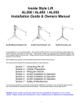
1
AL600 Pioneer
Hybrid Platform Lift (HPL)
Installation Guide & Owner’s Manual
Congratulations on your new lift purchase. The AL600 Pioneer is one of the easiest
and most trouble free ways to transport your chair or scooter. This manual is written
to be used both as an installation guide as well as an operation guide for the end user
Refer to the index below for the sections that apply to your lift and options.
Please read the manual thoroughly BEFORE attempting any installation,
adjustment or use of the lift.
Both installers and operators should familiarize themselves with this entire manual.
If you have any questions or comments concerning the installation or operation of your
scooter/chair lift, please contact your local distributor for additional technical information.
Only authorized dealers should install this lift.
Caution: Some scooters and chairs may be unsuitable for transport in or on a
motor vehicle. Please contact the manufacturer of your mobility device to
determine its transportability.
Unpacking the Lift
Detailed below is the inventory of parts included with your lift. If any parts are missing or if any
shipping damage is noted, immediately contact the distributor from which you purchased your lift.
DO NOT attempt to install or use the lift with any missing or damaged parts.
Box Contents:
1
1
1
1
1
1
Lift Assembly
Pioneer Platform
Leg Assembly
Hardware Pack
Foot Plate
Front Wheel Cradle
(For Scooter Applications)
Lift Assembly
Pioneer Platform
Front Wheel Cradle (for Scooter Applications)
Pioneer Hardware Pack:
Leg Assembly
Foot Plate
Owner’s Manual
Vehicle Wiring Harness
2 Button Hand Control
Manual Override Tool
Hex Bolts DIA 5/16” x 4”
Hex Nuts DIA 5/16”
Washers 5/16”
Lock Washers 5/16”
Installation Washers
Butt Connectors 10-12 gauge
Rubber Grommet
Tie Wraps
1
1
1
1
2
2
2
2
2
2
1
10
Applications: The Pioneer in its factory setup is intended for the transport of power chairs. With a
minor change to the platform the Pioneer can easily be adapted for the transport of three or four
wheel scooters. The maximum weight that can be safely lifted by the Pioneer in either setup is 350
LBS. This lift is intended for installation in the enclosed rear cargo area of most vans, mini-vans,
and S.U.V.s. This lift is not intended for use with vehicles with tailgates. This lift is not intended for
application where it would be left outdoors.
Installing the Vehicle Wiring Harness
Important Note: IMPROPER WIRING IS THE #1 CAUSE OF PROBLEMS IN THE OPERATION OF A VEHICLE LIFT.
FOLLOW THE WIRING INSTRUCTIONS CAREFULLY
Located in the hardware package is the vehicle wiring harness. The harness is manufactured to, and complies with the
SAE J1128 requirements. The wire harness is approximately 23 ft. long and will accommodate most vehicles.
Unwind the harness and lay it flat. One end of the
harness has a black plug . This is the lift end of the
harness and goes to the back of the vehicle.
To back
of vehicle
To vehicle's
battery
E
C
LA
IR
KW
B
Begin routing the wiring harness at the vehicle battery.
Attach the black wire to the negative terminal on the battery.
Do not attach the red wire yet.
E
CK
R
WI
A
BL
OR
Top mount
Side mount
Run the wiring harness under or when possible through
the vehicle, back to the trailer hitch. Always locate the wiring
harness where it can not be snagged by road debris and
away from the vehicles gas tank.
If the harness is too long for the vehicle, coil the
excess wire and secure it to the vehicle frame with
the supplied tie wraps. Do not cut or shorten the
harness. Secure the plug about even with the end of
the hitch receiver tube.
E
RE
D
R
WI
Attach the red wire to the positive terminal on the battery.
RED WIRE
Important Reminder: Never attempt to attach the wire harness
to a secondary power source, The lift requires direct connection
to the battery.
Side mount
OR
Top mount
Caution:
When the installation requires the wiring harness be run on the underside of a vehicle,
route the harness away from the exhaust system, brake lines, fuel lines, gas tank, pinch points, and sharp edges.
Locate the wiring harness where it can not be snagged by road debris.
Manufactures Recommendation: Schedule a routine maintenance visit with the end user. Harmar recommends
the lift be greased in the applicable areas, and the wire harness connections be checked for corrosion,
and/or decay, as such conditions are normal due to environmental changes.
Installing in Vehicles with a Removable Third Row Seat
Preparing the vehicle’s cargo area: Most mini vans, vans
and some S.U.V.s have a removable third row seat.
Forinstallations in these vehicles,
remove this seat. If your vehicle
does not have a removable
third row seat, see the
next page for instructions.
Installing the Leg Assembly: Place the leg assembly into
the vehicle. Orientate the leg assembly as shown in the
drawing to the right. Hook both of the J-Bolts into the third
row seat attachment points. Verify that the leg assembly is
centered from side to side within the vehicle. Tighten the
nuts on the J-bolts until the assembly is firmly attached to the
vehicle. At this time the foot plate should be placed in the
vehicle near the rear opening. This will support the two
rearmost feet of the lift and keep the feet from pressing into
the floor pan of the vehicle.
Install the 4 Leveling Pads from
the hardware pack at this time.
Each Pad will thread into the
underside of the base at
each corner. Leveling
adjustment can be after
the lift has been installed.
S
AIR
H
RC
WE
PO
This part of the leg
assembly must
face toward the
rear of the vehicle.
J-Bolt Bracket: These parts
must face toward the rear of
the vehicle. Secure the JBolts into the 3rd row seat
attachment points.
R
TE
OO
SC
IR
HA
C
ER
W
PO
Leg Assembly
This part of the
J-Bolt must
face toward the
front of the
vehicle
Leg
Assembly
Placing the lift into the vehicle: Pick up the lift and place it
into the vehicle’s cargo area. This operation will require two
people to perform. Take care during this operation not to
scratch the vehicle’s interior. Position the lift such that it
will be one inch inside of the rear door. Verify this by
closing the rear door and inspecting the fit from inside of the
vehicle.
If your vehicle has a lip at the rear door you will need to
use the adjustable feet to raise the entire lift so that all of
its moving parts will clear the door lip.
R
TE
O
CO
Foot Plate
Middle Stage
Use a wrench to extend the adjustable feet until the lift’s
middle stage will clear the door lip and door latch by 0.5”.
Leveling the lift: The floor in some vehicles is not level.
To level the lift start by parking the vehicle on level ground.
Use a carpenter’s level to verify the lift is level. If it is not,
adjust the four feet until the lift is level.
Attaching the lift into the vehicle: The leg assembly has
two sets of large holes in its upper surface. When installing
a Pioneer for use with a scooter, select the holes that will
offset the lift to the driver’s side of the vehicle. When
installing the Pioneer for use with a power chair, select the
holes that will offset the lift to the passenger's side of the
vehicle. Insert both hold down rods into the holes in the Leg
Assembly. If needed you may slide the hold down brackets
along the lifts body so that the hold down rods line up with
the holes in the top of the leg assembly. Crossbolt the hold
down rods in place with the supplied hardware. Tighten the
5/8” nuts on the hold down rods, until the lift is attached
securely to the vehicle.
Caution: Do not remove the hold down brackets and
reattach them on the opposite side of the Platform Keeper.
Rear Door Lip
Foot Plate
Adjustable Feet
Hold Down Brackets
Hold Down Rod
PLATFORM
KEEPER
Installing in Vehicles Without a Removable Third Row Seat
Installing the Leg Assembly: Place the leg assembly into
the vehicle. Orientate the leg assembly as shown in the
drawing to the right. Also place the foot plate in the vehicle
near the rear opening. This will support the two rearmost
feet of the lift and keep the feet from pressing into the floor
pan of the vehicle.
Leg Assembly
Install the 4 Leveling Pads from
the hardware pack at this time.
Each Pad will thread into the
underside of the base at
each corner. Leveling
adjustment can be after
the lift has been installed.
Pick up the lift and place it into the vehicle’s cargo area. This
operation will require two people to perform. Take care
during this operation not to scratch the vehicle’s interior.
Position the lift such that it will be one inch inside of the rear
door. Verify this by closing the rear door and inspecting the
fit from inside of the vehicle.
Position the leg assembly so that it is located in line with the
hold down rods on either side of the lift. (See the picture at
the bottom of this page.) If needed you may slide the hold
down brackets along the lift’s body.
AIR
R
TE
OO
SC
R
WE
CH
PO
IR
R
TE
HA
OO ER C
C
S
W
PO
5/16 x 4” Bolt
5/16” Washer
5/16” Nut
This part of the leg assembly must
face toward the rear of the vehicle.
Foot Plate
Installation
Washer
5/16” Lock
Washer
Leg Assembly
Remove the J-bolts from the leg assembly and replace them
with the hardware shown in the drawing to the right. Use an
11/32” drill bit to drill holes though the vehicle floor for
attaching the 5/16” bolts.
Caution! Inspect the underside of the vehicle for obstacles
before drilling any holes. Avoid the vehicle’s wiring, fuel
lines, fuel tanks, spare tires, seat cushions, etc.
From beneath the vehicle attach the installation washers,
5/16” lock washers and 5/16” nuts. Verify that the leg
assembly is centered from side to side within the vehicle.
Tighten the nuts on the 5/16” bolts until the assembly is
firmly attached to the vehicle.
If the vehicle has a lip at the rear door you will need to use
the adjustable feet to raise the entire lift so that all ofits
moving parts will clear the door lip.
Middle Stage
Use a wrench to extend the adjustable feet until the lift’s
middle stage will clear the door lip and door latch by 0.5”.
Leveling the lift: The floor in some vehicles is not level.
To level the lift start by parking the vehicle on level
ground. Use a carpenter’s level to verify the lift is level.
If it is not, adjust the four feet until the lift is level.
Attaching the lift into the vehicle: The leg assembly has
two sets of large holes in its upper surface. When
installing a Pioneer for use with a scooter, select the holes
that will offset the lift to the driver’s side of the vehicle.
When installing the Pioneer for use with a power chair,
select the holes that will offset the lift to the passenger's
side of the vehicle. Insert both hold down rods into the
holes in the Leg Assembly. Crossbolt the hold down rods
in place with the supplied hardware. Tighten the 5/8” nuts
on the hold down rods, until the lift is attached securely to
the vehicle.
Caution: Do not remove the hold down brackets and
reattach them on the opposite side of the Platform Keeper.
Rear Door Lip
Foot Plate
Adjustable Feet
Hold Down Brackets
Hold Down Rod
PLATFORM
KEEPER
Installing the Pioneer
Connecting the Electrical Components:
Plug the hand control into the vehicle wiring
harness. Then plug the other end into the
electrical harness located on the rear of the
lift.
Extending the Lift: Push the down button
on the hand control to extend the lift in the
horizontal direction.
CAUTION: Watch the lift as it extends.
Make sure the moving components of the
lift do not rub against the vehicle’s
interior, door lip, or door latch. You may
need to stop and adjust the lifts height, by
repeating the steps on the installation page.
When the lift is fully extended, it will start to
run down in the vertical direction. At this
point stop the lift. If you are using the
Pioneer to lift power chairs the platform is
now ready to be installed. If you are using
the Pioneer to transport scooters, follow the
instructions on the Page 8 for how to modify
the platform for use with a Scooter.
Installing the Platform for use with a
Power Chair:
Bolt the platform to the lift assembly as
shown to the right using the supplied
1/2” diameter and 5/16” diameter
hex bolts.
Hand Control
Vehicle Wiring Harness
Lift
Preparing the Power Chair or Scooter for the Pioneer
There are 2 options on how to attach the strap hooks to the chair that are included with the lift.
Anchor Plate: The Anchor Plate is a flat plate that is 20” long with 2 slots in each end. This plate
will work with any chair or scooter that has a center seat post that attaches to the bottom of the seat.
Attach the Anchor Plate by the following steps.
1. Remove the seat from the chair and turn it over.
2. Loosen the screws that attach the plate to the bottom of the seat. Allow enough room to slide the Anchor Plate
between the seat and the seat plate.
3. Attach the Anchor Plate in the center of the seat plate with the holes on each end extending evenly on each
side of the seat.
4. Retighten the screws that hold the seat plate to the bottom of the seat.
5. Replace the seat on the chair.
The Anchor Plate should extend about 1-1/2” out from the side of the seat cushion. This will allow the user to attach
the strap hooks to the Anchor Plate to secure the chair to the lift.
Anchor U-Bolts: The U-Bolts are to be used with Power Chairs or Scooters that do not have a center seat post.
On this type of chair, the seat is normally attached to a tubular frame. Attach the U-Bolts, two on each side, to the
frame as shown below. Make sure that the loop extends to the outside of the chair to allow the strap hooks to be
attached by the end user.
Each type of chair will differ slightly and the placement of the U-bolts will differ between different models and manufacturers. Place the Anchor U-Bolts towards the center of the seat if possible. Because of the different types of
seats, you may be forced to attach the Anchor U-Bolts more towards the front or rear of the seat, but we recommend attachment as close as possible to the center of the seat.
Loading a Power Chair
Parking the Chair on the Platform: Before
loading the power chair, verify that the
platform has been lowered all the way to the
ground. Set your chair’s speed control at a
slow speed so that you may maneuver
comfortably onto the platform. You may drive
onto the platform from either side. Park the
chair such that it is centered on the platform.
Securing the Chair to the Platform: The
Pioneer platform has a restraint attached to
each corner of the platform. Each restraint
has a hook at the end. Place each hook in
either the anchor plate slot, or in each U-bolt.
Pull the loose end of each restraint tight.
To release, simply press the release tab, and
remove the hooks.
Folding Seat Backs: If your chair has a
folding seat back you may wish to fold it to the
down position. This will allow you more
clearance when loading the chair into the
vehicle. Depending on the size of your chair,
you may need to remove the head rest to
provide for sufficient clearance.
Raising the Chair: Before raising, verify that
the chair is secured to the platform. While
holding the hand control stand to the side and
away from the lift. Press the up button. The
lift will raise and retract into the vehicle. The
lift is retracted fully when the platform is fully
inside of the vehicle and the lift’s motion stops.
At this point release the button. Secure the
hand control by placing it on the hook and loop
patch attached to the lift. Close the rear door
carefully taking notice of any baskets,
backpacks or additional items attached to the
chair that may be hit by the door.
PUSH to
RELEASE
PULL to
TIGHTEN
Platform Preparation for Use with Scooters
Modifying the Platform for use with
Scooters:
Contained in the lift box will be the front wheel
scooter adapter. This must be attached to the
platform for all scooter applications.
Attach the front wheel scooter adapter using
the provided hardware to the platform end plates
on the passenger's side of the platform.
( Remove the two restraints, add the front wheel
craddle, and reassemble the restraints in
the same holes from which they were removed )
Installing the Platform for use with a
Power Chair:
Bolt the platform to the lift assembly as
shown to the right using the supplied
1/2” diameter and 5/16” diameter
hex bolts.
Loading a Scooter
Parking the Scooter on the Platform: Before
loading the scooter, verify that the platform has
been lowered all the way to the ground. Set
your scooter’s speed control at a slow speed so
that you may maneuver comfortably onto the
platform. You must driv e onto the platform
from the driver’s side of the vehicle. Park the
scooter such that the front wheel(s) is(are) on top
of the front wheel scooter adapter.
Securing the Scooter to the Platform: The
Pioneer platform has a restraint attached to
each corner of the platform. Each restraint
has a hook at the end. Place each hook in
either the anchor plate slot, or in each U-bolt.
Pull the loose end of each restraint tight.
To release, simply press the release tab, and
remove the hooks.
Folding Seat Backs: If your scooter has a
folding seat back you may wish to fold it to the
down position. This will allow you more
clearance when loading the scooter into the
vehicle. Depending on the size of your
scooter, you may need to remove the head rest
to provide sufficient clearance.
Stowing the Scooter: While holding the hand
control, stand to the side and away from the
lift. Press the up button again. The lift will
raise and retract into the vehicle. The lift is
retracted fully when the platform is inside of
the vehicle and the lift’s motion stops. At this
point release the button. Secure the hand
control by placing it on the hook and loop
patch attached to the lift. Close the rear door
carefully taking notice of any baskets,
backpacks or additional items attached to the
scooter that may be hit by the door.
PUSH to
RELEASE
PULL to
TIGHTEN
SAFETY:
·
·
·
·
·
·
Caution: Do not operate this lift until your dealer has satisfactorily instructed you in the proper operation of the lift.
Your Harmar lift has been engineered and designed for years of trouble free use. Although, with everyday use,
some parts may become loose or worn. IMPORTANT! Check regularly for any worn, loose or damaged parts of
your lift. If anything is observed, DO NOT USE THE LIFT! Contact your dealer or installer of the lift for repairs to
be made. Failure to act may cause severe injury!
Your Harmar lift should only be used for the loading and unloading of scooters and power wheelchairs for which it is
designed. DO NOT add to or modify any part of the lift system without first contacting the manufacturer of the lift.
Any modifications may void any warranties as well as effect the structural integrity of the lift.
Always make sure the vehicle’s parking brake is firmly set before operating the lift.
Caution: When using the lift, keep your hands and feet from under the scooter or power chair as it is being loaded
or unloaded.
Warning: This lift is not meant for human transport. The mobility device and platform must be unoccupied before
operating the lift.
MAINTENANCE:
The Harmar lift has been designed to be as trouble free as possible for the owner. But, as with any mechanical device,
regular care should be given while owning and using this device. Maintenance should be performed regularly.
·
·
We recommend that dealers schedule a preventative maintenance inspection at least once a year on motors, lift
frame, wiring harness and all moving parts of the lift.
Check for paint chips and touch up any bare metal with a good gloss black enamel or lacquer to inhibit rust. This
may be necessary more frequently when subjected to salt air or road salt.
TROUBLESHOOTING:
PROBLEM: The lift will not operate or operates slowly.
Possible Causes:
Bad Connection - Verify the vehicle wiring harness is tightly attached to the battery and that there is no build up on the
terminals.
Battery - Check to see if the battery needs to be replaced or if the terminals are corroded. Clean the terminals if any
corrosion is present. 12 volts should be present at the lifting motors from the vehicles battery. This can be tested with a
voltage meter.
PROBLEM: Intermittent power to the lift. The lift will operate for a short period of time and quit. At a later time it will
start working again.
Possible Causes:
Circuit Breaker - Although the breaker resets itself automatically, it may be malfunctioning and need to be replaced.
Check for power at the lift with a test lamp.
Bad Connection - Verify the vehicle wiring harness is tightly attached to the battery and that there is no build upon the
terminals.
Hand Control - Test by bypassing the hand control. Do this for only a second or two. The lift, vehicle, scooter or chair
may be damaged if continuous power is left supplied to the unit.
PROBLEM: Platform will not sit level on the ground.
Possible Causes:
Terrain - Verify that the vehicle is parked on flat level ground.
Orientation of the lift’s base - Adjust the lift’s four feet until the platform sits level on the ground.