1
iNSTALLATiON
AND SERVICE MUST BE PERFORMED
BY
A QUALiFiED iNSTALLER.
iMPORTANT: SAVE FOR LOCAL ELECTRICAL
iNSPECTOR'S
USE.
EAD AND SAVE THESE iNSTRUCTiONS
FOR FUTURE REFERENCE.
if the information
causing
property
damage,
in this manual
personal
is not followed
exactly, a fire or explosion
may result
injury or death.
FOR YOUR SAFETY:
B
Do not store or use gasoline or other flammable
appliance.
WHAT TO DO IF YOU SMELL GAS:
*
*
Do not tryto light any appliance.
Do not touch any electrical switch;
*
*
Immediately call your gas supplier from a neighbor's phone. Follow the gas supplier's instructions.
if you cannot reach your gas supplier, call the fire department.
Installation and service must be performed by a qualified installer, service agency or the gas supplier.
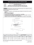
Cooktop Dimensions
vapors and liquids in the vicinity of this or any other
do not use any phone in your building.
30" Min.
(76.2 cm)
........... ......
B
.
C
Cooktop Cutout Dimensions
30"Model
30 (76.2) 211/2
(54.6) 21/2
(6.4)
26s/8
(67.6)
19(48.6)
All dimensions are in inches (cm).
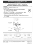
NOTE: Wiring diagram for this appliance is enclosed in this booklet.
263A(67.9)
281/2
(72.4)
191/16(48.4)
20 (50.8)
P/N 318201484
(0811 ) Rev. A
English - pages 1-10
Espafiol - pAginas 11-19
Wiring Diagram - pages 20
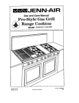
30" (76.2 cm)
Min. Clearance
Between the Top
of the Cooking
Platform and
nprot ect ed
Wood or Metal
---------_-¢U
13" (33 cm)
Max. Depth For
Cabinet Installed
Above Cooktop.
binet
18" Min.
(45.7 cm)
Dimension J is the Minimum
Distance Required Between
Rear of Top Panel to Adjacent
Combustible Surfaces.
Clearance
Dimension K is the
Dimension H is the
Minimum Clearance
Required From
Left Side of Top
Panel to Adjacent
Combustible Surface.
Minimum Clearance
Required From
Right Side of Top
Panel to Adjacent
Combustible Surface.
24" _
cm)
Allow Dimension L Space Below
Cooktop for Piping and Electrical
Connections.
_J__To
eliminate the risk of
burns or fire by reaching over heated
surfaces, cabinet storage space
located above the cooktop should be
avoided. If cabinet storage is provided,
risk can be reduced by installing a
range hood that projects horizontally
a minimum of 5" (12.7cm) beyond the
bottom of the cabinets.
[ 30"Models [
Figure 2 - COUNTERTOP
2
0" (0 cm)
J. 2" (5.1cm) J. 2" (5.1cm)
CUTOUT OPENING
81/8
'' (20.6cm)
important
1.
2.
3.
4.
5.
cabinets above the cooktop. Children could be
seriously burned climbing on the cooktop to reach
items.
To eliminate the need to reach over the surface
Notes to the Installer
Read all instructions contained in these installation
instructions before installing the cooktop.
Remove all packing material before connecting the
electrical supply to the cooktop.
Observe all governing codes and ordinances.
Be sure to leave these instructions with the
consumer.
Note: For operation at 2000 ft. elevations above see
level, appliance rating shall be reduced by 4 percent
for each additional 1000 ft.
Important
burners, cabinet storage space above the burners
should be avoided.
Adjust surface burner flame size so it does not
extend beyond the edge of the cooking utensil.
Excessive flame is hazardous.
Never use your cooktop for warming or heating
the room. Prolonged use of the cooktop without
adequate ventilation can be hazardous.
Do not store or use gasoline or other flammable
vapors and liquids near this or any other appliance.
Explosions or fires could result.
Note to the Consumer
Keep these instructions with your Use and Care Guide
for future reference.
I PO
I STR
NT SAFETY
CTI
The electrical power to the cooktop must
be shut off while gas line connections are being made.
Failure to do so could result in serious injury or death.
Safety Measures
Installation of this cooktop must conform with local
codes or, in the absence of local codes, with the
National Fuel Gas Code ANSI Z223.1 / NFPA No.54
in the United States, or in Canada, with the Canadian
Fuel Gas Code, CAN/CGA B149 and CAN/CGA
B149.2.
- Gas Surface
Units
Your new cooktop has been tested to meet the most
rigid safety standards. You can feel confident while
using it but use these safety suggestions to help avoid
accidents that can cause injury to the user or damage
to the cooktop.
Note: All safety measures listed may apply to your
model.
This cooktop has been design certified by CSA
International. As with any appliance using gas and
generating heat, there are certain safety precautions
you should follow. You will find them in the Use and
Care Guide., read it carefully.
Plug the unit into a 120-volt grounded outlet only.
Do not remove the grounding prong from the plug. If
in doubt about the grounding of the home electrical
system, it is the personal responsibility and obligation
of the owner to contact a qualified electrician and
have an ungrounded receptacle replaced by a
properly grounded three-prong wall receptacle, in
accordance with the National Electrical Code. Do not
use an extension cord with this unit.
Be sure your cooktop is installed and grounded
properly by a qualified installer or service technician.
This cooktop must be electrically grounded in
accordance with local codes or, in their absence, with
the National Electrical Code ANSl/NFPA No. 70-latest edition in the United States, or in Canada, with
the Canadian Electrical Code, CSA C22.1 Part 1.
The installation of appliances designed for
manufactured (mobile) home installation must
conform with Manufactured Home Construction and
Safety Standard Title 24CFR, Part 3280 [Formerly
the Federal Standard for Mobile Home Construction
and Safety, Title 24, HUD, (Part 280)] or when
such standard is not applicable the Standard for
Manufactured Home Installation 1982 (Manufactured
Home Sites, Communities and Set-Ups), ANSI
Z225.1/NFPA 501-A- latest edition, or with local
codes.
Do not store items of interest to children in the
Do not repair or replace any part of the unit unless
specifically recommended in this guide. Call a
qualified technician for all other servicing.
Clean only the parts of the cooktop as instructed in
the Use and Care Guide.
Be certain all packing materials are removed from
the unit before operating to prevent fire or smoke
damage, should the packing material ignite.
Ventilating
Hoods
Clean ventilating hood frequently. Grease should not
be allowed to accumulate on hood or filter.
When flaming foods under the hood turn the fan off.
The fan, if operating, may spread the flame.
3
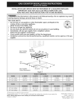
1. Wall Outlet Location
Safety on the Cooktop
Do not allow dry empty pans to heat on the cooktop
as this could ruin the pan and cause a fire hazard.
Do not use a wok on the cooking surface if it is
equipped with a round metal support placed over
the burner grate. This support acts as a heat trap
which may damage the burner grate, drip bowls and
burner head. It may also cause the burner to work
improperly and create a carbon monoxide hazard.
When lowering the cooktop be careful not to pinch
your fingers. Grasp sides of the top with fingertips
and lower into position.
,
12._
i
10"
J Recommended area for /
Important:
Please
120Vgrounded
Je on
rear wall.
Read Before Continuing
This appliance and its individual shutoff valve must be
disconnected from the gas supply piping system during
any pressure testing of that system exceeding Y2 psig.
outlet
/
_ _FRuLN_ET
22 "
NOTE: Ifan outlet
is not available,
have one installed by
This appliance must be isolated from the gas supply
pipping system by closing its individual manual shutoff
valve during any pressure testing of the gas supply
piping system equal to or less than Y2psig.
This cooktop is not approved for use with
downdraft systems.
_-OF
|
I
I
UNIT
Figure3
Disconnect the electrical supply before
servicing cooktop.
2. Secure
the Unit
Unit Clamp Down Information
Once the cooktop is installed and centered in the
counter opening, you must clamp the unit down as
shown. To clamp down, insert the offset side of the
angle bracket into the slots on each side of the unit.
Then run the thumb screw through the bracket and
up against the bottom of the counter. Tighten until
the unit draws down (figure 4).
Countertop
Cooktop
m
Angle Bracket
Burner Box
Figure 4
4
3. Provide an Adequate
Gas Supply
Manual
Shutoff
Valve
The cooktop covered in these installation instructions
is designed to operate on natural gas at 4" (10.2cm)
of manifold pressure or on LP gas at 10" (25.4cm) of
manifold pressure.
A convertible pressure regulator is supplied with each
surface unit and MUST BE CONNECTED IN SERIES
between the supply line and the valve manifold
regardless of which type of gas is being used.
_qJ_
Nip_Ple
Off
All connections
The convertible regulator for the surface units must be
located and turned in such manner to allow for easy
access to the convertible feature.
GAS FLOW
_'_
Flexible
Connector
Flare
Union
Pressure
Regulator
4,
Access
Cap
must be wrench-tightened
Figure 5
Assemble the flexible connector from the gas supply
pipe to the pressure regulator in the following order:
1. manual shutoff valve
2. 1/2" nipple
3. 1/2" flare union adapter
4. flexible connector
For proper operation, the maximum inlet pressure to
the regulator must not exceed 14" (35.6cm) of water
column (W.C.) pressure for both LP and Natural Gas.
5. 1/2" flare union adapter
6. 1/2" nipple
7. pressure regulator
For checking the regulator, the inlet pressure must
be at least 1" (2.5cm) (or 2.5 kPa) greater than the
regulator manifold pressure setting. If the regulator
is set for 4" (10.2cm) of manifold pressure, the inlet
pressure must be at least 5"(12.7cm). If the regulator is
set for 10" (25.4cm), the inlet pressure must be at least
11" (27.9cm).
Use pipe-joint compound made for use with Natural
and LP/Propane gas to seal all gas connections. If
flexible connectors are used, be certain connectors are
not kinked.
The supply line must be equipped with an approved
manual shutoff valve. This valve should be located
The gas supply line to the cooktops should be W'
(1.3cm) or 3A"(1.9cm) pipe.
4. Connection
Flare
Union
in the same room as the cooktop and should be in a
location that allows ease of opening and closing. Do
not block access to the shutoff valve. The valve is for
to gas
IMPORTANT: Remove all packing material and
literature from cooktop before connecting gas and
electrical supply to the appliance.
turning on or shutting off gas to the appliance.
Seal all openings in the wall behind the cooktop and
in the floor under the cooktop after gas supply line is
installed.
Install Pressure
Regulator
Install the pressure regulator with the arrow on the
regulator pointing up toward the unit in a position
where you can reach the access cap.
Shutoff Valve =
Open position
Figure 6
Do not make the connection too tight.
The regulator is die cast. Overtightening may crack the
regulator resulting in a gas leak and possible fire or
explosion.
Once regulator is in place, open the shutoff valve in
the gas supply line. Wait a few minutes for gas to move
through the gas line.
Check for leaks. After connecting cooktop gas, check
system for leaks with a manometer. If a manometer is
not available, turn on the gas supply and use a liquid
leak detector (or soap and water) at all joints and
connections to check for leaks.
5
Donotuseflameto checkfor leaksfrom
gasconnections.
Checkingforleakswitha flamemay
resultina fire or explosion.
Cap position
NAT
Tightenallconnectionsif necessaryto preventgas
leakageinthe cooktopor supplyline.
Checkalignmentof controlknobvalvesafter
connecting
the cooktopto the gassupplyto be
surethecooktopmanifoldpipehasnotmoved.A
misalignment
couldcausethevalvestemsto rubon
thecontrolpanel,resultingin a gasleakatthevalve.
Figure 8
,
Disconnect
the cooktopandits individualmanual
shutoffvalvefromthegassupplypipingsystemduring
anypressuretestingof thatsystemat a test pressure
greaterthan Y2psig (3.5 Kpa or 14" water column).
Turn the plug over so that the nib on the end of the
cap faces upward and re-insert into the cap (Figure
9). Rotate the plug 90° degrees in either direction to
lock it into the cap (Figure 10).
Isolate the cooktop from the gas supply piping system
by closing its individual manual shutoff valve during
any pressure testing of the gas supply piping system at
a test pressures equal to or less than Y2 psig (3.5 Kpa
or 14" water column).
Figure 9
,
5. LP/Propane
A. Pressure
Gas Conversion
Regulator
Reinstall the cap and plug securely onto the
regulator (Figure 11).
Conversion
Note: = Do not remove the Pressure Regulator.
If in doubt about the pressure at the manifold,
use a manometer. The inlet pressure on the
regulator must be at least 1" W.C. higher than
the outlet pressure. Inlet pressure on the
regulator must never exceed 14" W.C.
,
Figure 10
Cap
for LP
Unscrew the hex shaped cap and turn it over to
access the conversion plug inside the cap (Figure 7).
Figure 11
B=
Burner
Valves
Conversion
(see figure 12 and 13)
f
J
\._oj)
Figure 7
,
Rotate the plug 90° degrees in either direction to
align the tabs on the plug with the notches in the
cap (Figure 8).
Figure 12
6
1. Removevalveknobs,topgrates,burnerpans
andliftcooktopto gainaccesstovalves.
Locatevalvehoods(orifices)on backsideof
valves.
2a. ToconvertburnervalvesfromNaturalGas
to LPGas,usea wrenchtoturn valvehoods
(orifices)downuntilsnugagainstthe mixerpin
(approximately
2 V2turns).Donotovertighten.
2b. ToconvertburnervalvesfromLP Gasto
NaturalGas,usea wrenchto turnvalvehoods
(orifices)upuntiltheyareclearlyawayfromthe
mixerpin(approximately
2 V2turns).
3. Applygastothe burnerandadjustairshutter
onburnertubeto properflame(referto
picturesin '"BurnerFlameAdjustment"
section
forcomparison).
PinHood
NaturalGas__"_"'
B. Burner
Flame Adjustment
1. Proper Air Adjustment
(figure 15)
If the air shutter is properly adjusted, flame will be
steady, relatively quiet, and will have approximately
W' sharp blue cones. With LP gas, this usually
occurs when shutters are fully open.
Figure 15
2.Too Much Air (figure 16)
If the air shutter is adjusted so that too much
air flows into the burner, the flame will appear
unsteady, will possibly not burn all the way around,
and will be noisy (like a blowtorch).
LPGas
Hoodnuti__
j
Figure 13
6. Adjustments
A. Burner
Air Shutter
Adjustment
The air shutter adjustment for each of the four burners
is located at the open end of the tube on the valve
hood. The shutter is held in place by friction fit.
Figure 16
3. Not Enough Air (figure 17)
If the air to the burner is insufficient, you will not
see any sharp blue cones in flame. The flame may
burn with yellow tips, and soot will accumulate on
utensils used on the burner.
Air Shutter
Figure 14
If the air shutter needs adjusting, rotate the shutter to
allow more or less air to the burner tubes as needed.
The unit is set for Natural Gas at approximately 50%
opening of air shutter. For flame adjustment it might be
necessary to rotate the air shutter to some point less
than 50%; for LP Gas conversion the air shutter needs
to be rotated to a full open setting for a normal flame.
Figure 17
7
7. Connect
Electrical
Electricity
to Gas Cooktop
Situations where appliance power cord will be
disconnected frequently. Do not use an adaptor plug
in these situations because disconnecting of the
power cord places undue strain on the adaptor and
leads to eventual failure of the adaptor terminal. The
customer should have 2-prong wall receptacle replaced
by a 3-prong (grounding) receptacle by a qualified
electrician before using the appliance.
Requirements
120 volt, 60 Hertz, properly grounded branch circuit
protected by a 15 amp circuit breaker or time delay
fuse. Do not use an extension cord with this cooktop.
IMPORTANT Please read carefully.
For personal safety, these appliances
grounded.
must be properly
Disconnect electrical supply cord from
wall receptacle before servicing cooktop.
The power cord of these appliances is equipped with a
3-prong (grounding) plug which mates with a standard
3-prong grounding wall receptacle (see Figure 18) to
minimize the possibility of electric shock hazard from
this appliance.
8. Check Operation
Refer to the Use and Care Guide packaged with the
cooktop for operating instructions and for care and
cleaning of your cooktop.
The wall receptacle and circuit should be checked by
a qualified electrician to make sure the receptacle is
properly grounded.
Where a standard 2-prong wall receptacle is installed,
Do not touch the burners. They may be hot enough to
cause burns.
,
Preferred Method
Grounding
type wall
receptacle
Do not, under any
circumstances, cut,
remove, or bypass
the grounding
prong.
Check the Igniters
Operation of electric igniters should be checked
after cooktop and supply line connectors have
been carefully checked for leaks and the cooktop
has been connected to electric power.
To check for proper lighting, push in and turn
a burner knob to the LITE position. The burner
should light when gas is available to burner. Once
the burner lights, the burner knob should be turned
out of the LITE position. Try each knob separately
until all burners have been checked out.
Power supply cord with
3-prong grounding plug
Figure 18
it is the personal responsibility and obligation of the
consumer to have it replaced by a properly grounded
3-prong wall receptacle.
The burners can be lit manually during an electrical
power outage. To light a burner, hold a lit match
to the burner head, then slowly turn the Surface
Control knob to LITE. Use caution when lighting
burners manually.
Do not, under any circumstances, cut or remove the
third (ground) prong from the power cord.
Surface burner in use when an electrical power
failure occurs will continue to operate normally.
If an external electrical source is used, the appliance,
when installed, must be electrically grounded in
accordance with local codes or in their absence of local
codes with the National Electric Code ANSI/NFPA No.
70-1987 or latest edition.
The surface burners on models equipped with
pilots can operate during an electrical power
outage.
Check all code rules and regulations for connecting the
cooktop to be certain the installation conforms with all
local, municipal and state codes as well as local utility
regulations.
Failure to comply with the above could
result in a serious shock hazard.
Note: All hookups and adjustment shall be performed
by qualified technicians.
8
,
Model
Adjust the "LO" or "SIMMER" Setting of Surface
Burner Valves (see Figure 19)
Push in and turn each control knob to the "LO" (or
"SIMMER") setting. The "LO" setting of each burner
has been set at the factory to the lowest setting
available to provide reliable re-ignition of the
burner. If it does not stay lit on the "LO" setting,
check the setting as follows.
B.
C,
D.
Your serial plate also tells you the rating of the burners,
the type of fuel and the pressure the cooktop was
adjusted for when it left the factory.
Allow cooktop to cool to room temperature.
Light all burners by turning each control knob
to LITE until burners ignite, and then set them
at "HI".
Improper installation adjustment,
alteration, service or maintenance can cause injury or
property damage. Refer to this manual. For assistance
or additional information consult a qualified installer,
service agency, manufacturer (dealer) or the gas
supplier.
Quickly_ turn the knob to the LOWEST
POSITION for the burner you want to adjust.
If burner goes out, readjust valve as follows:
Remove the surface burner control knob, insert
a thin-bladed screw driver into the hollow valve
Stepping, leaning or sitting on this
cooktop can result in serious injuries and also cause
damage to the cooktop.
Be sure to keep appliance clear of combustible
materials, gasoline and other flammable vapors and
liquids.
decrease turn clockwise. Adjust flame until
you can quickly turn knob from HI to LOWEST
POSITION without extinguishing the flame.
Flame should be as small as possible without
going out.
If you need to adjust another burner, repeat
the steps from A to D above until all burners
operate properly.
_l__i_
w Valve
Before You Call for Service
Read the Before You Call for Service Checklist and
operating instructions in your Use and Care Guide.
It may save you time and expense. The list includes
common occurrences that are not the result of
defective workmanship or materials in this appliance.
Refer to your Use and Care Guide for Sears service
phone numbers, or call 1-800-4-MY-HOME ®.Please
call if you have inquiries about your product and/or
need to order parts.
Stem
Cooktop
Removal
If removing the cooktop is necessary for cleaning or
maintenance:
Figure 19
When All Hookups
Location
When ordering parts for or making inquires about your
range, always be sure to include the model and serial
numbers and a lot number or letter from the serial plate
of your cooktop.
stem and engage the slotted screw inside.
Flame size can be increased or decreased
with the turn of the screw. To increase flame
size turn the screw counterclockwise and to
E,
Number
The serial plate is located into the burner box near the
burner support or under the burner box.
_Be
extremely careful when
performing this operation.
A.
and Serial
1 .Shut off gas supply.
2.Disconnect the gas and electric supply.
3. Remove the installation screws which secure the unit
are Complete
Make sure all controls are left in the OFF position.
to the cabinet at the front and rear or the mounting
brackets on the right and left side of the burner box.
4. Remove the unit for servicing and cleaning.
Make sure the flow of combustion and ventilation air to
the cooktop is unobstructed.
Reinstall in opposite manner and order of removal and
check gas connection for leaks.
9
Notes
10
LEAY
POR UN INSTALADOR CALIFICADO.
IMPORTANTE: GUARDE ESTAS INSTRUCCIONES
LA INSTALACION
Y ELINSPECTOR
SERVICIO DEBEN
SER REALIZADOS
PARA USO DEL
ELECTRICO
LOCAL.
GUARDE ESTAS INSTRUCCIONES
PARA FUTURAS REFERENCIAS
Si todas las instrucciones de _ste manual no son observadas a la letra, se puede ocurrir
incendios o explosiones que pueden causar daSos materiales, lesiones o la muerte.
PARA SU SEGURIDAD:
-- No almacene o utilice gasolina u otros vapores y liquidos
artefacto.
-- QUE HACER Sl HAY FUGAS DE GAS
inflamables cerca de _ste o cualquier otto
•
•
•
No intente de encender ning_n artefacto
No toque ning_n interruptor el_ctrico; no utilice ning_n aparato telefbnico en su edificio.
Llame inmediatamente el abastecedor de gas desde el tel_fono de un vecino. Siga las instrucciones del
abastecedor de gas.
• En caso que no puede contactar el abastecedor de gas Ilame al departamento de bomberos.
= La instaiaci6n y el servicio telef6nico deben set realizados pot un instalador calificado, pot un servicio
t_cnico
certificado o pot el abastecedor
de gas.
Dimensiones de la
plancha de cocinar a
gas
30" Min.
(76.2 cm)
C
Dimensiones del hueco
para la plancha de
cocinar a gas
Figura 1
30" M0del0
21Y2(54.6)
21/2(6.4)
26s/8(67.6)
19(48.6)
263A(67.9) 281/2
(72.4) 191/18
(48.4)
Todas las dimensiones se dan en pulgadas (cm).
NOTA: Se adjunta los diagramas de cables de esta plancha de cocinar con el liberta.
P/N 318201484 (081 1) Rev.A
English- pages 1-10
Espa_ol - paginas 11-19
Diagrama de la instalaci6n alb,mbrica - pb,gina 20
30" (76.2 cm)
MAx. profundidad
de gabinetes
instalados por
encima de la
plancha de
empotar es 13"
(33 cm).
A tMf-nT.
Dimensiones J este minimo
distancia entre el borde
posterior del hueco y la mas
cerca superficie combustible por
encima del mostrador.
t"
18" Mfn.
(45.7 cm)
minimo desde el
lado izquierdo de
almacenamiento de
combustible.
¢
Espacio
Dimensiones
Dimensiones
K este espacio
Mfnimo entre la
parte superior de
la plataforma
de la plancha de
cocinar y el fondo
de una madera
non protegida o
armario met¢41ico.
H este espacio
minimo desde el
lado derecho de
almacenamiento de
combustible.
[
24" (61 cm)
No es posible utilisar cajones con esta plancha
de cocinar porque la caja de empalme se
extiende de L dimensiones por encima de la
superficie del mostrador.
Para eliminar el riesgo
de alargar sobre los unidades en
calentamiento de la superficie, deberfa
evitarse el espacio de almacenamiento
del armario, ubicado sobre las unidades
de la superficie. Si se cuenta con este
espacio, se puede disminuir el peligro
instalando una cubierta de cocina
que se extienda horizontalmente en
5" minimo por sobre la parte inferior
delantera en los armarios.
! ! ! ! ! ! ! ! ! !i ! !i i! i i
Figura 2 - DESENO DEL ARMARIO
12
Notas
importantes
sobrepase el borde del utensilio de la plancha de
cocinar.
para el instalador
1. Lea todas las instrucciones de instalaci6n antes de
realizar la instalaci6n de la plancha de cocinar.
2. Retire todos los articulos de embalaje antes de
realizar las conexiones electricas a la plancha de
cocinar.
3. Observe todos los c6digos o reglamentos estatales
4. AsegQrese que el consumidor tenga estas
instrucciones.
5. Nota: Para la utilizaci6n a m_s de 2 000 pies de
altura, la potencia del aparato deberA ser reducida de
4 por ciento a cada 1 000 pies adicionales.
Notas
importantes
No utilice jamAs su plancha de cocinar como
calefactor. El uso prolongado de la cocina sin la
ventilaci6n adecuada puede ser peligroso.
No guarde o haga uso de gasolina o otros vapores
y liquidos inflamables acerca de este o cualquier
aparato. Se puede resultar en incendios o
explosiones.
El suministro electrico a la plancha de
cocinar debe de ser cerrado durante las conexiones
a la linea. De Io contrario se puede resultar lesiones
graves o la muerte.
para el consumidor
Guarde todas las instrucciones con su manual del
usuario para futuras referencias.
Recomendaciones
de seguridad
unidades
de superficie
INSTRUCCIONES DE
SEGURIDAD IiVlPORTANTES
para
Su nueva plancha para cocinar ha sido probada
para cumplir los mAs altos estandares de seguridad.
Usted puede sentirse seguro al usarfa. Pero siga las
siguientes recomendaciones de seguridad para evitar
accidentes que puedan lastimar a quien Io usa o daRar
de la plancha de cocinar.
La instalaci6n de esta plancha de cocinar debe
realizarse en conformidad con los c6digos locales o, si
estos no existen, con el National Fuel Gas Code ANSI
Z223.1/NFPA 54, o en Canada, con el Canadian Fuel
Gas Code, CAN/CGA B149 y CAN/CGA B149.2.
AIgunas recomendaciones
aplicar a su modelo.
El dise_o de esta plancha de cocinar cuenta con la
aprobaci6n de la CSA International. AI igual que todos
los artefactos a gas que generan calor, deben seguirse
ciertas medidas de seguridad. Vienen con el Manual de
uso y mantenimiento. Lea el manual atentamente.
de seguridad pueden no
Conecte la unidad Qnicamente a un toma de 120
voltios con conexi6n a tierra. Si existe alguna
duda acerca de la conexi6n a tierra del sistema
electrico de la casa, es responsabilidad y obligaci6n
del due5o contactar a un electricista calificado y
hacer reemplazar el toma sin tierra por un toma de
tres patas conectado a tierra que siga el National
Electric Code. Con esta unidad no deben usares
extensiones.
Asegure que la plancha de cocinar sea instalada
correctamente por un instalador o tecnico calificado.
La plancha de cocinar debe conectarse
electricamente a tierra de acuerdo con los c6digos
locales o, de no existir, con el c6digo electrico ANSI/
NFPA No. 70 - QItima edici6n en los Estados Unidos,
or in Canada, con el Canadian Electrical Code, CSA
C22.1 Parte 1.
La instalaci6n de las unidades diseRados para casas
(moviles) deben estar de acuerdo con: "Manufactured
Home Construction and Safety Standards tittle
24 CFR, part of 3280 (anteriormente The Federal
Standard for Mobile Home Construction and Safety,
tittle 24, HUD, Part 280)", o cuando los estandares
no son aplicables the "Standard for Manufactured
Home Installation 1982 (Manufactured Home Sites,
Communities and Set-ups ) ANSI Z225.1-NFPA501A"o Qltima edici6n o con los c6digos locales.
No almacene articulos que interesan los ni_os en
los armarios que estan por encima de la plancha de
cocinar. Les podrfa causar quemaduras gravas si
intentan subirse para alcanzarlos.
* DeberAn eliminarse los armarios sobre los
quemadores para evitar el contacto entre ambos.
Grade el tamaRo de la llama de modo que no
No repare o reemplace ninguna parte de la estufa a
menos que se recomiende en forma explicita en este
manual. Llame a un tecnico calificado para cualquier
otro tipo de servicio.
Limpie Onicamente las partes de la estufa como se
recomienda en la Gu[a de Usuario.
AsegQrese de que todos los materiales de empaque
ban sido removidos de la unidad antes de usarla,
para prevenir da5o por fuego o humo en caso de
incendiarse el material de empaque.
E×tractores
de aire
• Limpie los extractores frecuentemente. No se debe
dejar acumular grasa en el extractor o en el filtro.
• Cuando los alimentenos esten dando llama, apague
el extractor; este puede expandir la llama.
13
Medidas
plancha
de seguridad
de cocinar
1. Area para la torna de corriente
para el uso de la
12"
= No coloque recipientes de cocina secos y vacios
encima de las parrillas pues esto los daSarfa y se
correHa peligro de incendio.
No use un wok (sart6n chino) en la plancha
de cocinar si viene con el anillo met&lico para
sostenerla. Este anJllo act(Ja como una trampa de
calor que puede daSar la parrilla del quemador, las
cocas y el mismo quemador. Adem&s puede hacer
que el quemador funcione mal. Esto puede generar
niveles indeseados de mon6xido de carbono que
serfan perjudiciales para la salud.
Aseg0rese de no lastimarse los dedos a! cerrar la
plancha de cocinar. Sujete la plancha con las puntas
de los dedos y bajela.
Irnportante:
Por favor lea antes
continuar con la instalaci6n
I
cm) 'l
'l
.3 cm) lJJ4_
/
',
10"
I
(25.4 cm)
I Area recomendada para I
' la toma de corriente
i a tierra de 120V en el
NOTA: Si no
existe una toma
de corriente,
contacte a un
electricista calificado
para realizar la
instalaci6n,
de
El aparato y su valvula de apagado deben ser
desconectados del sistema de suministro de gas
durante cualquier prueba de presi6n del sistema a una
presi6n de prueba en exceso de 1/2 psig.
' pared posterior.
CL de pared
, y unidad
i
/
Figura 3
La unidad debe estar aislada del suministro de gas
cerrando la valvula manual de cierre durante cualquier
prueba del sistema del suministro de gas a una
presi6n de prueba igual o menor que 1/2 psig.
2. Fijaci6n
I
,
i
22"
(55.9cm)
|
I. 11
j1_/
"CL de suelo
de la unidad
Una vez que el aparato est_ instalado y centraro en
la apertura del mostrador, se fiene que sujetar como
se indica.
Esta cocina no debe de usar con
sistemas de ventilaci6n descendente.
Para ajustar el aparato, inserte el soporte, con
el lado desviado, en la ranura en cada Iodo del
aparato. El tomillo que se puede girar con los dedos
debe entonces de pasar a traves del soporte y
hasta la parte de abajo del mostrador. Apri6telo
hasta que el aparato se quede ajustado (vea la
figura 4).
-IEL21_._i,_,._II Desconecte la corriente el6ctrica antes
de hacer mantenimiento a este electrodom6stico.
Plancha de
cocinar
Mostrador
Brida de fijaci6n
Caja del quemador
Figura 4
14
3. Provea un adecuado
suministro
de gas
Valvula de
cierre
manual
Las planchas de cocinar abarcadas en estas
instrucciones de instalaci6n estAn dise_adas para
funcionar con gas natural de 4" (10.2 cm) de multiple
de admisi6n o con gas propano de 10" (25.4 cm) de
multiple de admisi6n.
A_(_er
(
Se conecta un regulador de presi6n convertible en
serie al multiple a la cocina que debe permanecer en
serie con la linea de suministro de gas, que no tiene
en cuenta si estA utilizado gas natural o gas propano.
FLUJO DEL GAS
_"
Uni6n
_
) \__ Boquilla
Apagado
_t
Conector
flexible
(Off)
Regulator
de presi6n
_
Boquill_i
...................
Tapa de
entrada
Todas las conexiones deben ajustarse con
una Ilave de tuerca
Figura 5
Monte el conector flexible del tubo del suministro de gas
al regulador de presi6n en funcionamiento:
1. vMvula de cierre manual
2. boquilla de 1/2"
3. adaptador de 1/2"
4. conector flexible
5. adaptador de 1/2"
6. boquilla de 1/2"
7. regulador de presi6n.
El regulador convertible de las planchas de empotrar
debe ser Iocalizado y colocado de tal forma que
permita el acceso a la caracterfstica de ser convertible.
Para un manejo correcto, la presi6n de entrada
maxima hacia el regulador no debe exceder 14" (35.6
cm) de presi6n de la columna de agua.
Para controlar el regulador, la presi6n de entrada debe
ser de al menos 1" (2.5 cm) (o .3.4 kPa) mayor que el
ajuste de presi6n del multiple del regulador se ajusta
a 4" (10.2 cm) de la presi6n del multiple, la presi6n
de entrada debe ser de al menos 5" (12.7 cm). Si el
regulador se ajusta a 10" (25.4 cm), la presi6n de
entrada debe ser de al menos 11" (27.9 cm).
Utilice un compuesto de tubo articulado para uso de gas
natural y propano para sellar todas las conexiones de
gas. Si se utilizan conectores flexibles, asegQrese que
los conectores no estAn torcidos.
El tubo de suministro
de cierre certificada.
de gas deberia incluir una vMvula
Esta vMvula deberia estar ubicada
en la misma habitaci6n de la plancha de cocinar y
deberia estar en un lugar que permita una abertura y
cierre fAciles. No bloquee las entradas de la vMvula de
cierre. La vMvula sirve para abrir o cerrar el paso del gas
al artefacto.
La linea de suministro de gas por la cocina deberA
tener un tubo de V2"(1.3 cm) o 3A"(1.9 cm).
4. Cone×i6n
Uni6n
del gas
IMPORTANTE: Retirar todo el material de empaque y la
literatura de la cocina antes de conectar el suministro de
gas y de electricidad al aparato.
Selle todas las aberturas de la pared detrAs de la
plancha de cocinar yen suelo por debajo de la plancha
de cocinar despues la instalaci6n del suministro de
gas.
Instalar
el regulador
Vfilvula de cierre =
Abierta
Figura 6
de presi6n
Instalar el regulador de presi6n con la flecha del
regulador apuntando hacia la pieza y en una posici6n
que permita alcanzar la tapa de entrada.
Abra la vMvula de cierre en el tubo de suministro de gas.
Espere unos minutos para que el gas pase a traves del
tubo de gas.
F_l_m_No
ajuste demasiado
la conexi6n. El
regular esta fundida a presi6n. AI ajustar demasiado se
puede romper el regulador causando una fuga de gas y
un posible incendio o explosi6n.
Verifique para las fugas. Luego de conectar la
plancha de cocinar al gas, verifique el sistema con un
man6metro. Si no cuenta con este instrumento, cortar
todos los pilotos y de la vuelta al suministro de gas
de la plancha de cocinar y utilice un detector de fugas
liquidas en todas las articulaciones y conexiones para
verificar si existen fugas.
15
Noutilicellamalibreparaverificarla
existenciadefugas.Laverificaci6ndehs fugascon
unallamapuedeprovocarfuegoo explosi6n.
Posici6n de
la tapa para
NAT
Ajuste todas las conexiones en caso que sea
necesario, para evitar fugas de gas en la plancha de
cocinar o en el tubo de suministro de gas.
Figura 8
Verifique la alineacidn de las v_lvulas luego de
conectar la plancha de cocinar al suministro de gas
para asegurar que no se ha movido la valvula del
multiple. Una mala alineacidn puede inducir la friega
del tronco de perilla de la valvula sobre el panel de
control, y ocurrir en fugas en la valvula.
,
Desconecte la plancha de cocinar y su valvula de
cierre individual del sistema de tubefia durante
Voltee el tapdn de manera que el diente del extremo
de la tapa apunte hacia afuera y reinserte dentro
de la tapa (figura 9). Gire el tap6n 90 ° grados en
cualquier direcci6n para asegurarlo debajo de la
tapa (figura 10).
cualquier ensayo de presi6n del sistema en ensayos
de presi6n superiores a 1/2 psig.
Aparte la plancha de cocinar del sistema de tuberfa
del suministro de gas, cierrando su valvula de cierre
individual manual, durante cualquier ensayo de presi6n
del sistema de suministro de gas en ensayos iguales o
inferiores a 1/2 psig.
5. Conversion
A. Conversi6n
Figura 9
4.
de gas propano/licuado
el regulador
de presi6n
Figura 10
Vuelva a acomodar la tapa y el tap6n dentro del
regulador (figura 11).
Nota:
No quite el regulator de presi6n.
Use un man6metro para chequear la presi6n en el
multiple, si hay alguna duda. Recuerde la presidn
de entrada debe ser al menos 1" W.C. m_.s alta que
la presi6n de salida. La presi6n de entrada en al
regulador nunca debe exceder 14" W.C.
1.
Posici6n de
la tapa para
LP
Desatornille la tapa hexagonal y volteela para tener
acceso al tap6n de conversi6n debajo de la tapa
(figura 7).
B. Burner
Valves
Figura 11
Conversion
(vea figura 12 y figura 13)
)
Figura 7
,
Gire el tap6n 90 ° grados en cualquier direcci6n para
alinear las lengQetas en el tap6n con los agujeros
en la tapa (figura 8).
//j/J/
16
Figura 12
1. Remuevalosbotonesdecontroly levantela
cubiertadela planchadecocinar.Encontrar&
lascapuchasde lavalvulaen laparteposterior
de lavalvula.
2a. Paraconvertirla unidadde GasNaturala LP,
girela capuchade la valvulaaproximadamente
2 Y2vueltas. No apriete demasiado.
2b. Para convertir la unidad de LP a Gas Natural,
gire la capucha de la valvula aproximadamente
2 Y2vueltas en el sentido contrario alas
3.
B=
Ajuste de entrada de aire de la
superficie
del quernador
1. Ajuste de entrada de aire (figura 15)
Si la entrada de aire est_ ajustada correctamente,
la llama ser& estable, relativamente suave y tendr&
un cono azul fuerte de aproximadamente W' (1.3
cm). Con gas LP propano, se puede ocurrir cuando
la entrada de aire esta totalmente abierta.
manecillas del reloj. Esto separarA la capucha
del pasador mezclador.
Proporcione gas al quemador y ajuste el
piloto y el obturador de gas en el venturi para
obtener una llama adecuada. (para comparar,
utilice los illustracions 15 a 17).
Pasador-_
€,-Capucha
Figura 15
2. Demasiado Aire (figura 16)
Si el obturador de aire estA dejando pasar
demasiado aire al quemador, la llama serA
inestable, posiblemente no habrA llama a todo el
rededor del quemador, y esta serA ruidosa (como
un soplete).
Gas Natural,,-,
Figura 13
6. Ajustes
A. Ajustes de obturador de aire del quemador.
El ajuste del obturador de aire para cada uno de los
cuatro quemadores y del homo estA Iocalizado en el
extremo abierto del venturi y ajusta la capucha de la
vAIvula. El obturador se mantiene en su lugar mediante
ajuste por fricci6n.
Figura 16
3. Aire insuficiente
(figura 17)
Si la entrada de aire al quemador es insuficiente,
usted no ver& conos azul fuerte en la llama. La
llama podr_, tener puntas amarillas que causar[an
la acumulaci6n de hollin en los recipientes usados
sobre el quemador.
Ajuste _e aire
Figura 14
En caso de necesitar ajuste el obturador de aire, rote el
obturador de aire para permitir m&s o menos aire en el
quemador (segQn se necesite).
La unidad estA preparada para Gas Natural a una
abertura de aproximadamente el 50% del obturador de
aire. Para ajustar la llama puede ser necesario rotar
el obturador de aire a un punto menor a150%; para la
conversi6n de gas propano liquido, el obturador de aire
debe ser girado hasta que este totalmente abierto para
una llama normal.
Figura 17
17
7. Cone×i6n
de la electricidad
al
El incumplimentode las anteriores recomendaciones,
puede resultar en un peligroso choque electrico.
aparato
Requisitos
electricos
Un circuito de caRer[as conectado
Nota: Todas las conexiones deben ser hechas por
tecnicos calificados.
correctamente
a tierra de 120 voltios, 60 Herz protegidos por un
interruptor automAtico de 15 amp o un fusible de
retardo. No utilice un cable flexible de extensi6n en
Situaciones donde el cord6n de alimentaci6n del electrodomestico debe de ser frecuentemente desconectado.
esta plancha de cocinar.
No use un tap6n adaptador en estas situaciones porque
desconectar frecuentemente el cord6n de alimentaci6n
IMPORTANTE:
genera demasiado tirantez sobre el adaptador y puede
causar el ma! funcionamiento del borne del adaptador.
Es la responsabilidad del propietario de asegurarse que
un electricista calificado reemplaza una tomacorriente
de dos patas por una tomacorriente de tres patas (puesta a tierra), antes de usar el electrodomestico.
Por favor, lea atentamente.
Como medida de seguridad personal, este artefacto
debe conectarse a tierra correctamente.
El cable de encendido de este artefacto incluye un
enchufe de tres patas (de conexi6n a tierra) que calza
con un enchufe de pared estb.ndar de tres patas
de conexi6n a tierra (Figura 18) para disminuir la
posibilidad de peligro de choques electricos desde el
artefacto.
Desconecte
el cable electrico del toma
de la pared antes de hacer mantenimiento.
8. Verifique
la operaci6n
Se aconseja al consumidor que un electricista
calificado verifique el enchufe de pared y el circuito
para asegurar que el enchufe este conectado a tierra
correctamente.
Refiera el Manual del usuario que viene con la plancha
de cocinar para las instrucciones de funcionamiento
y el mantenimiento y la limpieza de su plancha de
cocinar.
Metodo Preferido
No toque a los quemadores. Pueden estar
suficientemente calientes par causar quemaduras.
No debe, bajo
ninguna circunstan@
cortar o retirar la
Enchure
1.
tercera pata del cable
de encendido
de pared
a tierra
Cablo de encendido
con enchufe de tres
Verifique los dispositivos de encendido (algunos
modelos)
La manipulaci6n de los dispositivos de encendido
electrico deberAn verificarse tras haber revisado
detenidamente la plancha de cocinar y los
conectores del tubo del suministro de fugas y
tras haber conectado la plancha de cocinar al
suministro electrico.
patas a tierra
Figura 18
En caso de encontrarse con un enchufe de pared
est_.ndar de dos patas, es la personal responsibilidad
y la obligaci6n del consumidor reemplazarlo por el
enchufe de pared de tres patas correspondiente.
Para verificar el correcto encendido, presione
hacia adentro y gire una valvula de quemador
superior hasta la posici6n "ENCENDIDO" (LITE).
El quemador debe encender cuando tiene gas
disponible. Una vez el quemador encienda
debe cambiarse a una posici6n diferente a
"ENCENDIDO" (LITE). Cada valvula debe
chequearse independientemente
hasta que todos
los quemadores hallan sido revisados.
No debe, bajo ninguna circunstancia cortar o retirar la
tercera pata (tierra) del cable de encendido.
Si una fuente de electricidad es utilizada; el aparato
debe ser conectado a tierra de acuerdo con las
normas locales o de acuerdo las "National Electrical
Code", ANSI/NFPA NO. 70-1987 o ultima edici6n.
Durante un corte de energ[a electrica se pueden
encender los quemadores de la cubierta con una
cerilla. Acerque una cerilla encendida al quemador
y luego gire lentamente el bot6n a la posici6n
ENCENDIDO (LITE). Tenga extremo cuidado al
encender los quemadores en esta forma.
Verifique todos los c6digos, normas o regulaciones
para conectar el aparato para cerciorarse de que la
instalaci6n estb. de acuerdo a los cddigos locales,
estatales y de las empresas de servicio de energ[a
locales.
18
Losquemadores
de parrillaqueestenencendidos
cuandoocurrael corte de energia electrica
seguirAn funcionando
,
Localizaci6n
normalmente.
Verificar el ajuste "LO" o "SIMMER" (Planchas de
cocinar 30" solamente) (vea Figura 19)
Presionar y girar el bot6n de control al ajuste "LO"
(o "SIMMER"'). El ajuste "LO" de cada quemador
ha sido creado para fijarse al menor ajuste
disponible para entregar un reencendido confiable
del quemador Si no queda encendido en el ajuste
"LO", verificar el ajuste "LO" como se muestra a
continuaci6n.
A.
Dejar que la cocina se enfrfe a temperatura
ambiente.
B.
Encender todos los quemadores girando cada
bot6n de control hasta LITE para encender los
quemadores y fijarlos en HI.
Girar r_pidamente el quemador utilizado desde
HI hasta LOWEST POSITION.
C.
D.
E.
del modelo
y numero
de serie
La place de serie de su plancha de cocinar estb.
ubicada en la caja del quemador, cerca del soporte de
quemador o debajo de la caja de quemador. Ademas
de los n0meros de modelo y de serie, contiene la
informaci6n acerca de la potencia normal de los
quemadores, el tipo de combustible y el ajuste de
presi6n fijado en la fabrica.
AsegQrese de incluir el modelo, nQmero de serie y el
nQmero o letra del note que se encuentran en la placa,
en todo pedido de partes o solicitud de informaci6n
acerca de su plancha de cocinar.
Incorrectas ajustas de instalaci6n,
modificaciones y reparaciones pueden causar
quemaduras o daSos a la propiedad. Consulte este
manual. Para asistencia y m&s informaci6n, consulte
un instalador calificado, una agencia, la fabricante
(distribuidor) o el suministrador de gas.
Si el quemador se apaga, reajustar la valvula
como se muestra a continuaci6n:
Paraese, apoyarse o sentarse en las
puertas o cajones de esta estufa puede causar serias
lesiones personales y tambien puede da_ar la estufa.
No use gasolina u otros vapores o liquidos inflamables
cerca a este u otro aparato electrodomestico. Una
explosi6n o incendio podrfa ocurrir.
Retirar el bot6n de control del quemador,
insertar un destornillador de cuchillo delgado
en el v_stago del agujero de la v_lvula y
encajar el tornillo ranurado. El tama_o de la
llama se puede aumentar o disminuir girando
el tornillo. Graduar la llama hasta que se pueda
girar r_pidamente hacia abajo desde HI hasta
LOWEST POSITION sin apagar la llama. La
llama deber_ ser Io m_s baja posible y estable
sin apagarse.
Si se desea ajustar otro quemador, repetir
los pasos de A a D descritos hasta que los
quemadores funcionen correctamente.
Antes
de Ilamar
al servicio
Lea la secci6n Lista de Control de Averfas en su
Manual del Usuario. Esto le podr_ ahorrar tiempo
y gastos. Esta lista incluye ocurrencias comunes
que no son el resultado de defectos de materiales
fabricaci6n de este artefacto.
o
Lea la garantia y la informaci6n sobre el servicio en su
Manual del Usuario para obtener el nQmero de telefono
y la dirreci6n del servicio o Ilamar 1-888-SU-HOGAR sM.
Por favor Ilame o escriba si tiene preguntas acerca de
su estufa o necesita repuestos.
Cuidado,
valvulgO agujero de la
Figura 19
Cuando se hart realizado
de conexi6n
todos
limpieza
y mantenimiento
Cierre el suministro de gas en caso de ser necsario
remover la unidad para su limpieza o reparaci6n:
1 .Desconecte la linea de suministro de gas.
2. Remueva los tornillos de instalaci6n del marco
frontal y parrilla inferior. Hale hacia afuera apenas Io
necesario para poder desconectar del toma electrico.
3. Despues de desconectar del suministro electrico y
de gas
4. Remover la unidad para su limpieza o
mantenimiento.
los sisternas
Aseg[Jrese que todos los controles estb.n en la posici6n
de apagado.
Aseg0rese que el fhjo de combusti6n y ventilaci6n de
aire de la plancha de cocinar no esten obstruidos.
Reinstale siguiendo el procedimiento inverso.
Aseg0rese de nivelar la estufa y verificar que no halla
escapes en la conexi6n de gas.
19
TOP BURNER
IGNITER
OPTIONAL
OUEMADOR DE ENCENDIDO
SUPER[BR
OPCIONAL
BOUGIE
D' ALLUMAGE-BRULEUR
--1
CAUTION:
LABEL
ALL
LI
I
I
I
TOP BURNER
IGNITER
OPTIONAL
OUEMADOR
DE ENCENDIDO
SUPERIOR
OPCIONAL
BOUGIE
D'ALLUMAGE
BRULEUR
FACULTATIF
RIGHT
REAR
[GNSW.
[NT,ENC, TRASERO
OERECHO
INTERALLUM
D. AR
r I
F
E i
r
i
Bd-I
ERROR
VERIFY
PROPER
PRIOR
CAN
TODOS
REAL[ZAR
ET
LEFT
REAR
IGNSW
INT, ENC.TRASERO
IZOUIEROO
INTER, ALLUM,
GAP
E i
E i
i
BK I
LEFT
FRONT
IGN. SW
INT_ENC
DE
FRENTE
!ZOUIERDO
INTERALLUM
G. AV
L i
TOP BURNER
IGNITER
QUEHADOR DE ENCENDIDO
SUPERIOR
BOUGIE
D'ALLUMAGE-BRULEUR
8K-I
1]
ALAMBRES
PLEBE
CAUSAR
F!L
BRANCHEMENT
CAUSER
PEUT
ANTES
LOS
DE
OESCONECTAR
DE
LE
UNE
L'APPAREIL
DE
{NCORRECTO
EBTA
DEBRANCHEMENT
OPERATION
APRES
PAR
CONTROLES_ERROR
FUNCIONAMIENTO
AVANT
CONTROLS
OPERATION.
BERVICING
DE
UN
AVERTISSEMENT:
ETIOUETER
CHAQUE
RIGHT
FRONT
IGN_SW.
INTENC.
DE
FRENTE
DEBECHO
INTERALLUM.
D_AV.
BK I
E J
AFTER
SERVICING
AN[] DANGEROUS
Y PELIGROSO,
VER]OUE
SI EL FUNC[DNAH[ENTO
CORRECTO
OESPUES
DEL MANTENIMIENTO.
BK-;
E
LOS
WHEN
DISCONNECTION
IMPROPER
MANTEN]M[ENTO
FONCTIONNEMENT
TOP BURNER
I GNI TEA
0UEMADOR
DE ENCEND I DO SUPER I OR
BOUG[E
D'ALLUMAGE-BRULEUR
TO
CAUSE
OPERATION
AVISO:
ETIOUETE
ALAMBRAJE
i
t
i
WIRES
WIRING
DE
CEUX-CIUNE
DANGEREUSE,
TOUTE
VER[FIER
ERREUR
LE
DE
BON
REPARATION
LEFT
FRONT
[GN, SW,
[NT.ENC
DE
FRENTE
[ZOU/ERDO
[NTERALLUM.
G. AV,
LEFT
REAR
IGNSW
[NT ENCTRASERO
IZQUIERDO
INTERALLUH_
GAR
RIGHT
REAR
iGNSW
INTENCTRABERO
DERECHO
INTER, ALLUM.
DAR
8K-1
RIGHT
FRONT
IGNSW
INTENC
DE
FRENTE
DERECHO
INTERALLUM
D, AV
r i
F i
E i
E i
E i
E i
r
TOP
BURNER
OUEMADOR
BOUGIE
IGNITER
DE
ENCENDIDO
TOP BURNER
IGNITER
QUEMADOR DE ENCENOIDO
CONNECTOR
ENPALME
CONNECTEUR
BOUGIE
SUPERIOR
O'ALLUMAGE-BRULEUR
SUPERIOR
O'ALLUMAGE-BRULEUR
<_
O0
"_
GO
GROUND
M/SE
A
PUESTA
DISCONNECT
POWER BEFORE
SERVICING
UNIT,
AVISO
OESCONECTE
LA ENERGIA
ANTES
DE REALIZAR
EL HANTENIMIENT0
DEL ELECTRODOMEST/C0.
AVERT[SSEMENT
COUPER LE COURANT
AVANT
D'EFFECTUER
LA
REPARATION
COLOR CODE
BK BLACK
_7
/ CODIGOS
/
NERO
BLANCO
DE COLOR /
/ NOIR
7
BLANC
LA
TERRE
A
TIERRA_]
TOP BURNER
IGNITER
QUEHAOOR
DE ENCENDIOO
BOUGIE
POWER CORD
PARA TRANSPORTE
DE FUERZA
CABLE
D'ALIMENTAT[ON
D'ALLUMAGE-BRULEUR
TOP BURNER
OUEMADOR
BOUGIE
2
18
200
3304
I
2O
150
3321
SUPERIOR
_ .............
[GNITER
DE
ENCENDIDO
D'ALLUMAGE-BRULEUR
SUPERIOR
NOIGNITER
MODULE BOARD
CUADRO DE MODULO DE ENCENDIDO
BLOC CONNECTION
ALLUMEUR
_
CODE COLLEUR
_ ! RE
ALAMBRE
FIL
GAGE
MED [OA
CAL
TEMP.°C
STYLE
UL
_18047111
R£V
B