1
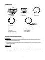
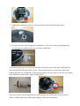
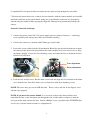
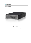
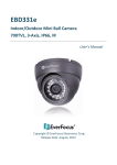
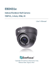
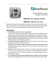
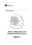
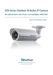
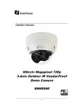
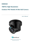
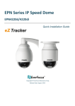
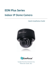
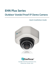
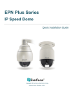
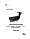
EVERFOCUS
High Resolution Vandal Proof
Weather Resistant 3-Axis IR Dome Camera
Operation Instructions
Model No.
EHD360
Please read this manual first for correct installation and operation. This manual should be retained
for future reference. The information in this manual was current when published. The
manufacturer reserves the right to revise and improve its products. All specifications are therefore
subject to change without notice.
PRECAUTIONS
1. Do not install the camera near electric or magnetic fields.
Install the camera away from TV/radio transmitters, magnets, electric motors, transformers
and audio speakers since the electromagnetic fields generated from these devices may distort
the video image or otherwise interfere with camera operation.
2.
Never disassemble the camera beyond the recommendations in this manual nor
introduce materials other than those recommended herein.
Improper disassembly or introduction of corrosive materials may result in equipment failure
or other damage.
3.
Try to avoid facing the camera toward the sun.
In some circumstances, direct sunlight may cause permanent damage to the sensor and/or
internal circuits, as well as creating unbalanced illumination beyond the capability of the
camera to compensate.
4.
Keep the power cord away from water and other liquids and never touch the power
cord with wet hands.
Touching a wet power cord with your hands or touching the power cord with wet hands may
result in electric shock.
5.
Never install the camera in areas exposed to oil, gas or solvents.
Oil, gas or solvents may result in equipment failure, electric shock or, in extreme cases, fire.
6.
Cleaning
For cameras with interchangeable lenses, do not touch the surface of the sensor directly with
the hands. Use lens tissue or a cotton tipped applicator and ethanol to clean the sensor and
the camera lens. Use a damp soft cloth to remove any dirt from the camera body. Please do
not use complex solvents, corrosive or abrasive agents for cleaning of any part of the camera.
Do not operate the camera beyond the specified temperature, humidity or power source
ratings. This camera is suitable for indoor and outdoor operation.
7.
Use the camera at temperatures within -10°C to +50°C (14°F to 122°F) and in an IP66
compliant environment; this device is not rated as submersible. The input power source is
12VDC. Be sure to connect the proper + / - polarity and voltage, as incorrect polarity or
too high a voltage will likely cause the camera to fail, and such damage is not covered
by the warranty. The use of properly fused or Class 2 power limited type supplies is
highly recommended.
8.
Mounting
Use care in selecting a solid mounting surface which will support the weight of the camera
plus any wind, snow, ice or other loading, and securely attach the camera to the mounting
surface using screws and anchors which will properly support the camera. If necessary (e.g.
when mounting to drop ceilings) use a safety wire to provide additional support for the
camera.
CAUTION
RISK OF ELECTRIC SHOCK
DO NOT OPEN
CAUTION:
TO REDUCE THE RISK OF ELECTRIC SHOCK, DO NOT REMOVE
COVER (OR BACK), NO USER SERVICEABLE PARTS INSIDE.
REFER SERVICING TO QUALIFIED SERVICE PERSONNEL.
OVERVIEW
The EHD360 is an outdoor, vandal resistant 3-axis IR dome camera which utilizes a Sony 1/3”
Super HAD CCD Sensor to provide high resolution 540TVL color video for security surveillance
applications. Vandal Proof materials and an IP66 weather resistant housing allow reliable
operation in outdoor and indoor environments. True day/night operation combined with 25m
(~80ft.) range high efficiency IR LEDs makes the EHD360 suitable for a wide range of day and
night surveillance situations. Plus, the 3-axis mechanical design and built-in f=3.7~12mm
varifocal auto iris lens bring flexibility to installation and field of view adjustment.
FEATURES
Color dome camera with SONY 1/3” Super HAD CCD sensor.
High resolution 540 TVL.
3-Axis design for flexible fens positioning.
High sensitivity, low smear, high anti-blooming and high S/N ratio.
Built-in Auto Gain Control (AGC), Auto Tracing White Balance (ATW).
Built-in 3.7~12mm varifocal DC-drive auto iris lens.
25m (~80ft.) range IR-LEDs.
True day/night auto switching with IR filter removal for B/W images in low light
environments.
Vandal proof to withstand impact of a 10 pound sledgehammer.
Weather resistant, IP66 rated.
PACKAGE CONTENTS
1
Camera Unit x 1
Mounting kit includes:
-Screws x 4
-Security wrench for housing screws x 1
-Expanding Screws x 4
-Washers x 4
Operation Instructions (this document) x 1
Weatherproof bushing x 1
Power cable x 1
Video cable x 1
Power adapter pigtail (for NTSC model only) x 1
Mounting template x 1
SPECIFICATIONS
Pickup Device
1/3" SONY Super HAD CCD Sensor
Video Format
NTSC or PAL (depends on model selected)
Picture Elements
768 x 494 (NTSC), 752 x 582 (PAL)
Horizontal Resolution
540 TVL
Sensitivity
0.12 LUX / F1.6 ; 0 LUX (IR LED ON)
S/N Ratio
Over 48dB (AGC off)
Electronic Shutter
1/60(1/50)s~1/100,000s
Video Output
BNC 1.0Vp-p 75Ω
Gamma Correction
0.45
Lens Type
Vari-Focal 3.7~12mm / F1.4 DC Drive Auto Iris Lens
Day/Night
True day/night with motorized IR cut filter
Gain Control
Automatic
White Balance
ATW (2500°K~9500°K)
Sync. Mode
Internal Sync.
IR LED
11 Units High Efficiency IR LED
IR Wavelength
850nm
IR Distance
25m (~80ft.) nominal; depends on environment
Weather Resistant
IP 66
Vandal Proof
Yes
Power Source
12VDC
Power Consumption
283mA @12VDC
Operating Temperature
-10°C~50°C / 14°F~122°F
Dimensions (O.D. x H)
142mm x 115.5mm / 5.6” x 4.55”
Weight
979 g / 2.16 lbs
Certifications
CE / FCC
2
DIMENSIONS
C
B
A
Dimensions
D
Bottom View
Front View
E
F
G
Top View
Bottom View
A. Lens
B. IR-LED
C. Side conduit entry
D. Back conduit entry
E. Inner plate mounting holes
F. BNC Connector
G. DC Connector
INSTALLATION INSTRUCTIONS
Drill the Holes
1. Locate the desired mounting location; position housing with camera pointed generally in the
desired direction and mark location.
2. Use template to fix hole locations. Drill 4 holes for mounting screws and insert plastic anchors
into holes after drilling.
Mounting Steps
1. Use the security wrench provided to loosen the 4 screws holding the dome cover.
2. Remove the dome cover. Attach the camera body to the mounting surface with the mounting
screws provided
3
3. Tighten the 4 mounting screws to secure the camera body to the mounting surface.
3. If you need to wire cable through side conduit hole, use a coin to remove the conduit plug;
save the plug as it will be used to close the rear conduit hole.
Back conduit
hole
Conduit plug
Side conduit hole
4. Disconnect the power and video wire from the camera board end of the wire. Gently pull the
wire out from under the plate until it is free. Using wrench or pliers, remove the weather tight
bushing from the rear conduit hole. Using the plug removed in step 3 above, close the rear conduit
hole (additional caulk or other sealant recommended).
5. Pass the camera end of the power/video cable through side conduit hole. Using wrench or
pliers, carefully tighten the weather tight bushing into the side conduit hole.
4
6. (Optional) Pass the power/video wire under the base plate and up through the center hole.
7. Position the power/video wire so that it does not interfere with the camera module and carefully
attach the connector to the camera board, being sure to position the connector so it fit properly
onto the tiny pins within. Failure to properly align this connector may permanently damage the
camera.
General Connection and Setup
1. Connect the power cord to DC 12V power supply (observe polarity for power – connecting
reverse polarity will damage the camera and void the warranty).
2. Connect the camera to a monitor with 75ohm type coaxial cable.
3. Loosen the screws which lock the tilt mechanism. Rotate the pan and tilt mechanisms to point
the camera in the desired direction. Rotate the camera module on its axis if necessary to align
the image ‘upright’. Loosen the lens adjusting screws and adjust the lens to obtain the desired
field of view and focus.
Tilt lock
2 places
Lens adjustment
Focus adjustment
4. Lock the lens and tilt screws. Put the dome cover back and align the clear window in the dome
cover with the lens. Attach the dome cover to dome base with the 4 mounting screws.
NOTE: The cover only goes on in ONE direction. There is a key and slot; if not aligned, cover
will not close properly.
NOTE: If you move the camera module, it is necessary to loosen the dome and liner and
reposition the liner so the lens points out through the slot, and the rubber seal presses onto the
clear part of the dome and not the liner. Loosen 4 Philips screws, reposition liner, TIGHTEN four
screws (else seal and vandal resistance is compromised).
5
EverFocus Electronics Corp.
EverFocus Taiwan:
EverFocus Europe - Germany:
12F, No.79, Sec. 1, Shin-Tai Wu Road,
Hsi-Chih, Taipei, Taiwan
TEL: +886 2 2698 2334
FAX: +886 2 2698 2380
www.everfocus.com.tw
Albert-Einstein-Strasse 1, D-46446
Emmerich, Germany
TEL: +49 2822 93940
FAX: +49 2822 939495
www.everfocus.de
marketing@everfocus.com.tw
info@everfocus.de
EverFocus China - Beijing:
Room 609, Technology Trade Building,
Shangdi Information Industry Base,
Haidian District, Beijing 100085, China
TEL: +86 10 6297 3336~39
FAX: +86 10 6297 1423
www.everfocus.com.cn
EverFocus China - Shenzhen:
4F, No. 2, D4 Building, Wan Yelong
Industrial Park, Tangtou Road, Shiyan,
Baoan, Shenzhen, Guangdong 518101, China
TEL: +86 755 2765 1313
FAX: +86 755 2765 0337
www.everfocus.com.cn
marketing@everfocus.com.cn
marketing@everfocus.com.cn
EverFocus USA - California:
EverFocus USA - New York:
1801 Highland Avenue, Unit A, Duarte, CA 91010,
USA
TEL: +1 626 844 8888
FAX: +1 626 844 8838
www.everfocus.com
415 Oser Avenue, Unit S, Hauppauge, NY 11788, USA
TEL: +1 631 436 5070
FAX: +1 631 436 5027
www.everfocus.com
sales@everfocus.com
sales@everfocus.com
EverFocus Japan:
EverFocus Europe - UK:
5F, Kinshicho City Building, 2-13-4
Koto-Bashi,Sumida-Ku, Tokyo, 130-0022, Japan
TEL: +81 3 5625 8188
FAX: +81 3 5625 8189
www.everfocus.co.jp
Unit 12, Spitfire Business Park,
Hawker Road, Croydon Surrey, CR0 4WD, UK
TEL: +44 20 8649 9757 / +44 845 430 9999
FAX: +44 20 8649 9907
www.everfocusuk.co.uk
salesuk@everfocus.com
info@everfocus.co.jp
EverFocus India:
Suite 803, Housefin Bhavan, C-21, Bandra Kurla
Complex, Bandra (East), Mumbai 400051, India
TEL: +91 22 6128 8700
FAX: +91 22 6128 8705
www.everfocus.in
sales@everfocus.in
Your EverFocus product is designed
and manufactured with high quality
materials and components which can
be recycled and reused.
This symbol means that electrical and
electronic equipment, at their
end-of-life, should be disposed of
separately from your household waste.
Please, dispose of this equipment at
your local community waste
collection/recycling centre.
In the European Union there are
separate collection systems for used
electrical and electronic product.
Please, help us to conserve the
environment we live in!
Ihr EverFocus Produkt wurde entwickelt
und hergestellt mit qualitativ
hochwertigen Materialien und
Komponenten, die recycelt und wieder
verwendet werden können.
Dieses Symbol bedeutet, dass
elektrische und elektronische Geräte am
Ende ihrer Nutzungsdauer vom
Hausmüll getrennt entsorgt werden
sollen.
Bitte entsorgen Sie dieses Gerät bei
Ihrer örtlichen kommunalen
Sammelstelle oder im Recycling Centre.
Helfen Sie uns bitte, die Umwelt zu
erhalten, in der wir leben!
6
Rev 2.0 – February 2012