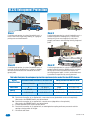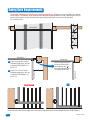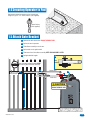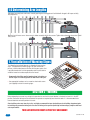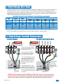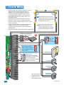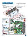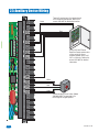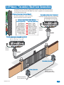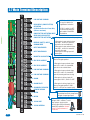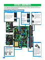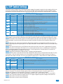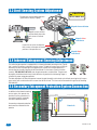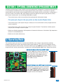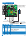
1
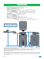
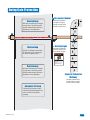
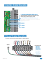
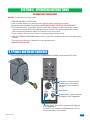
Owner’s Manual
Series 6500
Vehicular Swing Gate Operator
Copyright 2008 DoorKing, Inc. All rights reserved.
SPECIFICATIONS
Class of Operation
Type of Gate
Horsepower
Voltage / Phase
Current
Max Gate Weight
Max Gate Length
Cycles Per Hour
Speed
Entrapment Protection
Model 6500 - UL325 Class I, II, III, IV
Vehicular Swing Gates Only
1/2 or 1 HP
115 VAC Single-Phase, 230 VAC Single-Phase, 460 VAC Single-Phase
½ HP – 5.4 Amps @ 120V; 2.7 Amps @ 230V; 1.35 Amps @ 460V
1 HP – 9.7 Amps @ 120V; 4.9 Amps @ 230V; 2.5 Amps @ 460V
1/2 HP - 600 Lbs.; 1 HP - 800 Lbs.
1/2 HP - 18 Ft.; 1 HP - 22 Ft.
60 Per Hour
90° in approximately 12-14 seconds
Primary - Inherent entrapment sensing system (Type A)
Secondary - Provision for connection of a non-contact sensor (Type B1)
This manual is for 6500 operators
manufactured after July 12, 2008.
31 5/8”
31”
28
3/8”
18 3/8”
23 1/4”
Use this manual with the following models only:
6500-080, 6500-081, 6500-082*, 6500-083*, 6500-084, 6500-085, 6500-086*, 6500-087*, 6500-088, 6500-089*, 6500-090,
6500-091*, 6500-092, 6500-093*, 6500-094, 6500-095*, 6500-096, 6500-097*, 6500-098, 6500-099*.
*Optional Convenience Open System
DoorKing, Inc. reserves the right to make changes in the products described in this manual without notice and without obligation of DoorKing, Inc. to notify any
persons of any such revisions or changes. Additionally, DoorKing, Inc. makes no representations or warranties with respect to this manual. This manual is
copyrighted, all rights reserved. No portion of this manual may be copied, reproduced, translated, or reduced to any electronic medium without prior written
consent from DoorKing, Inc.
6500-065-K-7-08
1
SPECIFICATIONS
Gate Construction
4
Important Safety Instructions
4
Instructions regarding intended installation:
4
Important Notices
5
UL325 Entrapment Protection
6
Glossary
7
Swing Gate Requirements
8
Swing Gate Protection
9
SECTION 1 - INSTALLATION
10
1.1 Underground Conduit Requirements
10
1.2 Concrete Pad
10
1.3 Type of Installations
11-12
1.4 Securing Operator to Pad
13
1.5 Attach Gate Bracket
13
1.6 Determining Arm Lengths
14
1.7 Installation of Warning Signs
14
SECTION 2 - WIRING
2
1
14
2.1 High Voltage Wire Runs
15
2.2 High Voltage Terminal Connections
15
2.3 Control Wiring
16
2.4 Loop Detector Wiring
17
2.5 Auxiliary Device Wiring
18
2.6 Primary / Secondary (Dual) Gate Connection
19
2.7 Main Terminal Description
20
6500-065-K-7-08
2.8
Auxiliary Terminal Description
21
2.9
Secondary Operator Terminal Description
21
SECTION 3 - ADJUSTMENTS
22
3.1 Circuit Board Adjustments
22
3.2 DIP-Switch Settings
23
3.3 Limit Sensing System Adjustment
24
3.4 Inherent Entrapment Sensing Adjustment
24
3.5 Secondary Entrapment Protection System Connection
24
SECTION 4 - OPERATING INSTRUCTIONS
4.1 Power and Reset Switches
4.2 Shutdown Conditions
25
25
26-27
Soft Shutdown
Hard Shutdown
4.3 Manual Gate Operation
28
Emergency Vehicle Access Conditions
Manual Release
SECTION 5 - OPTIONAL CONVENIENCE OPEN ADJUSTMENTS
29
5.1 Operating Mode
29
5.2 DC System Description
30
5.3 DIP-Switch Settings
30
SECTION 6 - MAINTENANCE AND TROUBLESHOOTING
6.1 Maintenance
6.2 Troubleshooting
31
31
32-33
6.3 Built-in Diagnostics
34
6.4 Accessory Items
34
Model 6500’s Wiring Diagrams
6500-065-K-7-08
35-44
3
Gate Construction
Vehicular gates should be constructed and installed in accordance with ASTM F2200; Standard Specification for Automated
Vehicular Gate Construction. For a copy of this standard, contact ASTM directly at 610-832-9585; service@astm.org; or
www.astm.org.
Important Safety Instructions
WARNING - To reduce the risk of injury or death:
1. READ AND FOLLOW ALL INSTRUCTIONS.
2. Never let children operate or play with gate controls. Keep the remote control away from children.
3. Always keep people and objects away from gate. NO ONE SHOULD CROSS THE PATH OF THE MOVING GATE.
4. Test the operator monthly. The gate MUST reverse on contact with a rigid object or stop or reverse when an object
activates the non-contact sensors. After adjusting the force or the limit of travel, retest the gate operator. Failure to adjust
and retest the gate operator properly can increase the risk of injury or death.
5. Use the emergency release only when the gate is not moving.
6. KEEP GATES PROPERLY MAINTAINED. Read the owner's manual. Have a qualified service person make repairs to gate
hardware.
7. The entrance is for vehicles only. Pedestrians must use separate entrance.
8. SAVE THESE INSTRUCTIONS!
Instructions regarding intended installation:
• Install the gate operator only if:
1. The operator is appropriate for the construction of the gate and the usage class of the gate.
2. All openings of a horizontal slide gate are guarded or screened from the bottom of the gate to a minimum of 4 feet
(1.22 m) above the ground to prevent a 2 ¼ inch (57.2 mm) diameter sphere from passing through the openings
anywhere in the gate, and in that portion of the adjacent fence that the gate covers in the open position.
3. All exposed pinch points are eliminated or guarded.
4. Guarding is supplied for exposed rollers.
• The operator is intended for installation only on gates used for vehicles. Pedestrians must be supplied with a separate
access opening. The pedestrian access opening shall be designed to promote pedestrian usage. Locate the gate such that
persons will not come in contact with the vehicular gate during the entire path of travel of the vehicular gate.
• The gate must be installed in a location so that enough clearance is supplied between the gate and adjacent structures
when opening and closing to reduce the risk of entrapment. Swinging gates should not open into public access areas.
• The gate must be properly installed and work freely in both directions prior to the installation of the gate operator. Do not
over-tighten the operator clutch, pressure relief valve or reduce reversing sensitivity to compensate for a damaged gate.
• For gate operators utilizing Type D protection:
1. The gate operator controls must be placed so that the user has full view of the gate area when the gate is moving.
2. A warning placard shall be placed adjacent to the controls.
3. An automatic closing device (such as a timer, loop sensor, or similar device) shall not be employed.
4. No other activation device shall be connected.
• Controls intended for user activation must be located at least ten feet (10’) away from any moving part of the gate and
where the user is prevented from reaching over, under, around or through the gate to operate the controls. Outdoor or
easily accessible controls should have a security feature to prevent unauthorized use.
• The Stop and/or Reset button must be located in the line-of-sight of the gate. Activation of the reset control shall not
cause the operator to start.
• A minimum of two (2) WARNING SIGNS shall be installed, one on each side of the gate where easily visible.
• For gate operators utilizing a non-contact sensor:
1. See the instructions on the placement of non-contact sensors for each type of application.
2. Care shall be exercised to reduce the risk of nuisance tripping, such as when a vehicle trips the sensor while the gate
is still moving in the opening direction.
3. One or more non-contact sensors shall be located where the risk of entrapment or obstruction exist, such as the
perimeter reachable by a moving gate or barrier.
4
6500-065-K-7-08
• For gate operators utilizing contact sensors:
1. One or more contact sensors shall be located where the risk of entrapment or obstruction exist, such as at the
leading edge, trailing edge, and post mounted both inside and outside of a vehicular horizontal slide gate.
2. One or more contact sensors shall be located at the bottom edge of a vehicular vertical lift gate.
3. One or more contact sensors shall be located at the pinch point of a vehicular vertical pivot gate.
4. A hardwired contact sensor shall be located and its wiring arranged so that the communication between the sensor
and the gate operator is not subjected to mechanical damage.
5. A wireless contact sensor such as one that transmits radio frequency (RF) signals to the gate operator for
entrapment protection functions shall be located where the transmission of the signals are not obstructed or
impeded by building structures, natural landscaping or similar obstructions. A wireless contact sensor shall function
under the intended end-use conditions.
6. One or more contact sensors shall be located at the bottom edge of a vertical barrier (arm).
Important Notices
Vehicular gate operator products provide convenience and security. However, gate operators must use high levels of force
to move gates and most people underestimate the power of these systems and do not realize the potential hazards associated with an incorrectly designed or installed system. These hazards may include:
• Pinch points
• Entrapment areas
• Reach through hazards
• Absence of entrapment protection devices
• Improperly located access controls
• Absence of vehicle protection devices
• Absence of controlled pedestrian access
In addition to these potential hazards, automated vehicular gate systems must be installed in accordance with the UL-325
Safety Standard and the ASTM F2200 Construction Standard. Most lay persons are unaware of, or are not familiar with,
these standards. If an automated vehicular gate system is not properly designed, installed, used and maintained, serious
injuries or death can result. Be sure that the installer has instructed you on the proper operation of the gate and gate
operator system.
Be sure that the installer has trained you about the basic functions of the required reversing systems associated with your
gate operating system and how to test them. These include reversing loops, inherent reversing system, electric edges,
photoelectric cells, or other external devices.
• This Owner’s Manual is your property. Keep it in a safe place for future reference.
• Be sure that all access control devices are installed a minimum distance of 10 feet away from the gate and gate
operator, or in such a way that a person cannot touch the gate or gate operator while using the device. If access
control devices are installed in violation of these restrictions, immediately remove the gate operator from service
and contact your installing dealer.
• Loops and loop detectors, photo-cells or other equivalent devices must be installed to prevent the gate from
closing on vehicular traffic.
• The speed limit for vehicular traffic through the gate area is 5 MPH. Install speed bumps and signs to keep
vehicular traffic from speeding through the gate area. Failure to adhere to posted speed limits can result in
damage to the gate, gate operator, and to the vehicle.
• Be sure that all persons who will use the gate system are familiar with the proper use of the gate and gate
operator and are familiar with the possible hazards associated with the gate system.
• Be sure that warning signs are permanently installed on both sides of the gate in an area where they are fully
visible to traffic.
• It is your responsibility to periodically check all entrapment protection devices. If any of these devices are
observed to function improperly, remove the operator from service immediately and contact your installing or
servicing dealer.
• Follow the recommended maintenance schedule.
• Do not allow children to play in the area of the operator or to play with any gate-operating device.
• To remove the gate operator from service, operate the gate to the full open position and then shut off power to
the operator at the service panel.
6500-065-K-7-08
5
5
UL325 Entrapment Protection
Class I
Class II
A vehicular gate operator (or system) intended for use in a
home of one-to four single family dwelling, or a garage or
parking area associated therewith.
A vehicular gate operator (or system) intended for use in a
commercial location or building such as a multi-family
housing unit (five or more single family units) hotel,
garages, retail store or other building servicing the general
public.
STATE PRISON
Class III
Class IV
A vehicular gate operator (or system) intended for use in a
industrial location or building such as a factory or loading
dock area or other locations not intended to service the
general public.
A vehicular gate operator (or system) intended for use in a
guarded industrial location or building such as an airport
security area or other restricted access locations not
servicing the general public, in which unauthorized access
is prevented via supervision by security personnel.
This table illustrates the entrapment protection requirements for each of the four UL325 classes.
UL325
Classifications
Horizontal Slide, Vertical Lift, Vertical Pivot
Secondary Protection
Primary Protection
A
B1, B2 or D
A or C
A, B1, B2, C or D
Class III
A, B1 or B2
A, B1, B2, D or E
A, B1, B2 or C
A, B1, B2, C or D
Class IV
A, B1, B2 or D
A, B1, B2, D or E
A, B1, B2, C or D
A, B1, B2, C, D or E
Class I and II
Primary Protection
Swing and Vertical Barrier (arm)
Secondary Protection
A - Inherent entrapment protection system.
B1 - Provision for connection of, or supplied with, a non-contact sensor (photoelectric sensor or the equivalent).
When used as the PRIMARY device, must be monitored.
B2 - Provision for connection of, or supplied with, a contact sensor (edge device or the equivalent).
When used as the PRIMARY device, must be monitored.
C - Inherent adjustable clutch or pressure relief device.
D - Provision for connection of, or supplied with, an actuating device requiring continuous pressure to maintain
opening or closing motion of the gate.
E - An inherent audio alarm.
6
6
6500-065-K-7-08
Glossary
GATE - A moving barrier such as a swinging, sliding, raising, lowering, or the like, barrier, that is a stand-alone passage
barrier or is that portion of a wall or fence system that controls entrance and/or egress by persons or vehicles and
completes the perimeter of a defined area.
RESIDENTIAL VEHICULAR GATE OPERATOR – CLASS I - A vehicular gate operator (or system) intended for use in a home
of one-to four single family dwelling, or garage or parking area associated therewith.
COMMERCIAL / GENERAL ACCESS VEHICULAR GATE OPERATOR - CLASS II - A vehicular gate operator (or system)
intended for use in a commercial location or building such as a multi-family housing unit (five or more single family units),
hotels, garages, retail store, or other building servicing the general public.
INDUSTRIAL / LIMITED ACCESS VEHICULAR GATE OPERATOR - CLASS III - A vehicular gate operator (or system)
intended for use in an industrial location or building such as a factory or loading dock area or other locations not intended
to service the general public.
RESTRICTED ACCESS VEHICULAR GATE OPERATOR - CLASS IV - A vehicular gate operator (or system) intended for use in
a guarded industrial location or building such as an airport security area or other restricted access locations not servicing
the general public, in which unauthorized access is prevented via supervision by security personnel.
VEHICULAR BARRIER (ARM) OPERATOR (OR SYSTEM) - An operator (or system) that controls a cantilever type device (or
system), consisting of a mechanical arm or barrier that moves in a vertical arc, intended for vehicular traffic flow at
entrances or exits to areas such as parking garages, lots or toll areas.
VEHICULAR HORIZONTAL SLIDE-GATE OPERATOR (OR SYSTEM) - A vehicular gate operator (or system) that controls a
gate which slides in a horizontal direction that is intended for use for vehicular entrance and exit to a drive, parking lot, or
the like.
VEHICULAR SWING-GATE OPERATOR (OR SYSTEM) - A vehicular gate operator (or system) that controls a gate which
moves in an arc in a horizontal plane that is intended for use for vehicular entrance and exit to a drive, parking lot, or the
like.
SYSTEM - In the context of these requirements, a system refers to a group of interacting devices intended to perform a
common function.
WIRED CONTROL - A control implemented in a form of fixed physical interconnections between the control, the associated
devices, and an operator to perform predetermined functions in response to input signals.
WIRELESS CONTROL - A control implemented in means other than fixed physical interconnections (such as radio waves or
infrared beams) between the control, the associated devices, and an operator to perform predetermined functions in
response to input signals.
INHERENT ENTRAPMENT PROTECTION SYSTEM - A system, examples being a motor current or speed sensing system,
which provides protection against entrapment upon sensing an object and is incorporated as a permanent and integral part
of the operator.
EXTERNAL ENTRAPMENT PROTECTION DEVICE - A device, examples being an edge sensor, a photoelectric sensor, or
similar entrapment protection device, which provides protection against entrapment when activated and is not incorporated
as a permanent part of an operator.
ENTRAPMENT - The condition when an object is caught or held in a position that increases the risk of injury.
6500-065-K-7-08
7
7
Swing Gate Requirements
The operator is intended for installation only on gates used for vehicles. Pedestrians must be supplied with a separate
access opening. The pedestrian access opening shall be designed to promote pedestrian usage. Locate the gate such that
persons will not come in contact with the vehicular gate during the entire path of travel of the vehicular gate.
(ref. UL325 56.8.4.b)
Closed Gates
Closed Gate
Closed Gate
A
A If space is greater than 4 inches,
entrapment protection in this area
is required. ASTM F2200 7.1.1.1
and 7.1.1.2
Not Allowed
Opened Gate
entrapment protection in this area
is required. ASTM F2200 7.1.1.1
and 7.1.1.2
B
Opened Gate
B If space is less than 16 inches,
With the hinge mounted on
the corner of the pilaster,
the entrapment area A is
eliminated and protection is
not required for this area.
OK
Gates shall have smooth bottom edges, with vertical bottom edged protrusions not exceeding 0.50 inches. ASTM F2200 4.3
8
6500-065-K-7-08
Swing Gate Protection
C Non-contact Sensor
Minimizes the potential
of the gate closing on
vehicular or other traffic
that loops cannot sense.
Reverse Loop
Minimizes the potential of the gate
closing when a vehicle is present.
Number and placement of loops is
dependent on the application.
D
C
D
D Warning Signs
Shadow Loop
Permanently mounted
and easily visible from
either side of the gate.
Provides a hold open command to
the operator(s) only if the gate(s)
are at the full open position.
Moving Gate Can Cause
Serious Injury or Death
KEEP CLEAR! Gate may move at any time
without prior warning.
Do not let children operate the gate or play
in the gate area.
This entrance is for vehicles only.
Pedestrians must use separate entrance.
Reverse Loop
Minimizes the potential of the gate
closing when a vehicle is present.
Number and placement of loops is
dependent on the application.
Separate Pedestrian
Walkway
Located so pedestrians
cannot come in contact
with the vehicular gate.
Automatic Exit Loop
(Optional) will provide an open
command to the gate operator(s)
when a vehicle is exiting the
property.
6500-065-K-7-08
9
9
SECTION 1 - INSTALLATION
Prior to beginning the installation of the swing gate operator, we suggest that you become familiar with the
instructions, illustrations, and wiring guide-lines in this manual. This will help insure that your installation is
performed in an efficient and professional manner.
The proper installation of the vehicular swing gate operator is an extremely important and integral part of the
overall access control system. Check all local building ordinances and building codes prior to installing this
operator. Be sure your installation is in compliance with local codes.
1.1 Underground Conduit Requirements
Primary
Operator
Position
Secondary
Operator
Position
Primary/Secondary Interconnection Cable (Dual Operator Application Only)
Low Voltage Control and/or P.A.M.S. Wires
Loop Lead-In Wires
High Voltage Power
Concrete Pad
Sweeps 3/4 Inch Minimum
• The conduit requirements are for a typical swing gate operator installation (the secondary operator is shown for
those applications where a secondary operator may be used). The conduit requirements for your application may
vary from this depending on your specific needs.
• Use only sweeps for conduit bends. Do not use 90° connectors as this will make wire pulls very difficult and can
cause damage to wire insulation.
• We suggest that minimum 3/4-inch conduit be used.
CAUTION
• Be sure that all conduits are installed in accordance with local codes.
NEVER REMOVE HUB
after manual release.
1.2 Concrete Pad
Conduit Location
Back-up
Motor
Plate
5.5”
10”
28” Concrete Pad Length
12.5”
5”
31”
Conduit Area
4”
Electronics
Box
4” minimum
13”
22” Concrete Pad Width
10
Concrete pad
MUST be level.
Note: Bevel the
edges of concrete
pad to eliminate
water puddling
under the operator.
Underground depth of the concrete
pad is determined by soil conditions
and local building codes. Reinforced
concrete recommended.
22”
Approximate
Conduit Position
6500-065-K-7-08
1.3 Type of Installations
Standard Installation
Recommended for all gate lengths opening 90°.
46”
90°
14”
23”
38.5”
35”
3”
29.5”
28”
22”
Gate opens in approximately 15 seconds.
Concrete Pad
46”
Operator Installation
Concrete Pad Location
Standard Compact Installation
Recommended for gates up to 14 feet opening 90°.
42”
90°
13”
23”
32.5”
35”
2”
31.25”
28”
22”
Concrete Pad
Gate opens in approximately 12 seconds.
Concrete Pad Location
36”
Operator Installation
6500-065-K-7-08
Space Gained from Standard Compact Installation
90°
11
Compact Installation
Recommended for smaller gates up to 10 feet opening 90°.
34”
90°
13”
16.5”
26.5”
29.5”
2”
26.5”
28”
22”
Concrete Pad
Gate opens in approximately ?? seconds.
23”
Concrete Pad Location
Operator Installation
Gates Opening Wider than 90° Installation
90° Plus Installation requires the Standard Compact Installation’s concrete pad to be moved 2” away from the gate’s open
position. This distance of the gate’s arm will vary depending on how far the gate will open.
42”
Varies
23”
35”
Gate in
desired
open
position.
28”
22”
2”
Gate’s opening time will vary.
Concrete Pad is 2”
away from open gate.
Concrete Pad Location
12
Operator Installation
6500-065-K-7-08
1.4 Securing Operator to Pad
Permanently attach the operator to the concrete pad
using four (4) 3/8” x 3” sleeve anchors (not supplied).
3/8
Sleeve Anchor
(Not supplied)
1.5 Attach Gate Bracket
A Release hub with release tool. DO NOT REMOVE HUB!
B Bolt crank arm to operator.
C Slide elbow assembly on crank arm.
D Bolt control arm to gate bracket.
E Slide control arm into elbow assembly. KEEP ARM ASSEMBLY LEVEL.
F Bolt gate bracket to gate.
D
Gate
Bracket
Arm assembly and gate bracket MUST
be level for gate to function correctly.
F
E
D
Control Arm
Elbow
Assembly
Gate Bracket
Control Arm
A
B
C
Crank Arm
CAUTION
DO NOT REMOVE HUB!
31”
6500-065-K-7-08
13
1.6 Determining Arm Lengths
Slide elbow assembly back and fourth, manually opening and closing gate until satisfied with the gate’s 90° open and fully
closed positions.
Mark and cut off excess arms. Secure arms to elbow assembly with 6 allen screws. Tighten hub and replace release tool. Install
safety covers.
excess
excess
1.7 Installation of Warning Signs
This DoorKing Swing Gate Operator is shipped with two warning
signs. The purpose of the warning sign is to alert uninformed
persons, and to remind persons familiar with the gate system, that
a possible hazard exists so that appropriate action can be taken to
avoid the hazard or to reduce exposure to the hazard.
• Permanently install the supplied warning signs in locations so
that the signs are visible by persons on both sides of the gate.
• Use appropriate hardware such as wood or sheet metal screws
(not supplied) to install the warning signs.
SECTION 2 - WIRING
Before attempting to connect any wiring to the operator, be sure that the circuit breaker in the electrical panel is in the OFF
position. Permanent wiring must be installed to the operator as required by local electrical codes. It is recommended that a
licensed electrical contractor perform this work.
Since building codes vary from city to city, we highly recommend that you check with your local building department prior
to installing any permanent wiring to be sure that all wiring to the operator (both high and low voltage) complies with local
code requirements.
THIS GATE OPERATOR MUST BE PROPERLY GROUNDED!!
14
6500-065-K-7-08
2.1 High Voltage Wire Runs
The distance shown in the chart is measured in Feet from the operator to the power source. If power wiring is greater than
the maximum distance shown, it is recommended that a service feeder be installed. When large gauge wire is used, a
separate junction box must be installed for the operator connection. The wire table is based on stranded copper wire. Wire
run calculations are based on a 110 VAC power source with a 3% voltage drop on the power line, plus an additional 10%
reduction in distance to allow for other losses in the system.
This table illustrates the high voltage wire size and distance requirements.
Wire Size / Distance in Feet
Voltage
Amps
Required
Required
12 AWG
10 AWG
8 AWG
Model
Type
115
230
460
115
230
460
6500 1/2 HP
6500 1/2 HP
6500 1/2 HP
6500 1 HP
6500 1 HP
6500 1 HP
5.4
2.7
1.35
9.7
4.9
2.5
170
685
2,875
100
380
1,500
275
1,100
4,600
170
650
2,500
6 AWG
685
2750
11,500
520
1,600
6,500
460
1,830
7665
280
1,100
4,000
Reduce the wire distance in half for primary/secondary dual gate applications
Never run high voltage and low voltage wires in the same conduit. Keep them in separate conduits.
2.2 High Voltage Terminal Connections
115 VAC Hot
115 VAC Neu
HIGH VOLTAGE!
115 VAC Neu
HIGH VOLTAGE!
DANGER
230/460 VAC
DANGER
230 VAC/460 VAC Models
230/460 VAC
115 VAC
Neutral
115 VAC Models
• Route incoming high voltage
power through conduit and into
the operator as shown.
• Be sure wiring is installed in
Chassis accordance with local codes. Be
Ground sure to color code all wiring.
Chassis
Ground
• It is recommended that a surge
suppressor be installed on the
high voltage power lines to help
protect the operator and circuit
board from surges and power
fluctuations.
Electrical Box
Knock-outs
Conduit
• Secondary operator in a dual
operator application gets power
through the 8-wire connector that
links the 2 operators together. See
2.7 Primary/Secondary (dual) gate
connection.
For 230 and 460
Volt 3-phase
input, use only
two legs of the
incoming 3-phase
power.
Electrical Box
Knock-outs
Conduit
DO NOT cycle the operator without the OPEN and CLOSE limit sensors in their specific open
and close positions. The limit sensors or the AC power switch are the only ways to stop the operator once
an open cycle has started. This could cause damage to the gate and/or operator if the gate opens too far!
6500-065-K-7-08
15
2.3 Control Wiring
• Diagram at right is for illustration purposes. The actual
placement of the secondary protection devices is
dependent on the specific installation requirements.
• Secondary entrapment protection devices must be
installed with this gate operator. This protection may
be provided by non-contact or contact sensors, or a
combination of both.
• Secondary device wiring shows inputs to the circuit
board only. Photo-cells must be supplied with power.
• Refer to the safety instructions in the front of this manual
for more information.
• Controls must be installed a minimum of 10-feet from
the gate or installed in such a way that the person
using the control cannot come in contact with the gate
or gate operator.
• All inputs to the 4405 circuit board are Normally Open (N.O.).
20
16
Relay
Note: SW 1,
switch 3
must be ON.
24 Volt
Remote Terminal
Fire Box
Terminal 6 reverse input
functions only when gate is in
the closing cycle when SW 1,
switch 5 is OFF.
ON
13
14
15
16
17
18
19
Com
1 2 3 4 5 6 7 8
10
11
12
Reverses gate during the closing
cycle only. Holds gate in the full open
position until obstruction is cleared.
SW 1
ON
6
7
8
9
A
Stops the gate in the open cycle only.
Gate resumes normal operation when
the obstruction is cleared.
B Close direction non-contact sensor.
1 2 3 4 5 6 7 8
1
2
3
4
5
6
A Open direction non-contact sensor.
A
Radio Receiver power only.
Power is limited to 250 ma.
1
2
3
4
5
B
SW 1
Telephone Entry
24 Volt
Com
Magnetic Lock
Power (24-Volt DC) and logic
output. Power is shut off .5 sec.
prior to gate starting and
remains off while gate is opening
and in the open position.
Key Switch
Stand-Alone
Keypad
Note: All stand-alone
and telephone entry
devices must use a
separate power source.
Stand-Alone
Card Reader
6500-065-K-7-08
2.4 Loop Detector Wiring
• If other detectors are used, use a separate power
supply to power these detectors.
• Loop layout shown is for a typical swing gate
application with two-way traffic, or one-way exit
only traffic.
• Refer to the Loop Information Manual (available
from www.dkaccess.com) for more information
on loops and loop detectors.
Loops and loop detectors MUST be installed with this gate
operator to help prevent the gate from accidentally closing
on vehicular traffic.
• Loop detector wiring is shown for DoorKing plug-in loop
detectors only. If other loop detectors are used, refer to
the installation instructions supplied with those detectors
for wiring instructions.
se
r
eve
R
w
o
ad
Sh
se
r
eve
R
xit
E
tic
a
m
uto
A
2
3
4
5
9410
C
N
O
9409
N
Reverse loop lead in
wires are twisted
approx. 6 twists per
foot and are wired in
series.
Shadow Loop Output
SW 1
6
7
8
9
Note: Relay
must be set
to N.O.
Shadow loop lead in
wires are twisted
approx. 6 twists per
foot.
ON
Note: SW 1,
switches 5,
7 and 8
must be 1
OFF.
1 2 3 4 5 6 7 8
Automatic exit loop
lead in wires are
twisted approx. 6
twists per foot.
10
11
12
13
14
15
16
17
18
19
20
Com
N.O.
6500-065-K-7-08
17
2.5 Auxiliary Device Wiring
1
Terminal 5 required only if the tracker board
will activate the gate operator. Refer to the
manual 2351-065 for detailed information.
Green
2
3
4
5
Red
6
7
8
9
Using a 2351-010 Tracker
Expansion Board, operator data
can be sent to the access
controller. Models 1833, 1835,
1837 or 1838 only. Refer to the
manual 2351-065 for detailed
information.
10
11
12
13
14
15
16
17
18
19
White
Red
Green
The Remote Alarm Reset Station (Model
1404-080) MUST be mounted in the
line-of-sight of the gate operator.
20
18
6500-065-K-7-08
2.6 Primary / Secondary (Dual) Gate Connection
Connect the Primary / Secondary interconnection wiring as shown. Wire colors are based on
DoorKing interconnection cable (P/N 2600-75x). Power is supplied to the secondary operator
by the interconnection cable.
Primary Operator Control Board
Secondary Operator Terminal
• All control, loop detector, safety and auxiliary
devices are wired to the primary operator.
Primary Operator
(Red) Motor 1
(Blue) Motor 2
(White) Neutral 3
(Purple) 24VAC 4
(Yellow) Limit 5
(Brown) Spare 6
(Orange) Limit 7
(Gray) COM 8
10
11
12
13
14
15
16
17
18
19
20
Secondary Operator
Motor 1 (Red)
Motor 2 (Blue)
Neutral 3 (White)
24VAC 4 (Purple)
Limit 5 (Yellow)
Spare 6 (Brown)
Limit 7 (Orange)
COM 8 (Gray)
5
6
7
8
COM
4
Limit
3
Spare
2
Limit
Interconnection Cable Wiring
1
24VAC
• Secondary operator contains NO control board.
Neutral
6
7
8
9
Motor
2
3
4
5
Motor
1
Operator
Chassis
Ground
Conduit
1
2
3
4
5
6
7
8
Motor
Motor
Neutral
24VAC
Limit
Spare
Limit
COM
Primary Operator Second Terminal
ble
io
ect
Operator
Chassis
Ground
n
on
a
nC
erc
ar
nd
eco
Conduit
nt
yI
/S
ary
m
Pri
Secondary Operator
Primary Operator
Primary/secondary
interconnection cable
in underground conduit.
AC Power Conduit to
Primary Operator Only.
6500-065-K-7-08
19
19
2.7 Main Terminal Description
2
3
4
5
2. RADIO RELAY (SINGLE BUTTON)
ACTIVATION
6
7
8
9
6. REVERSE (SAFETY) INPUT/
SHADOW INPUT
4
• lf SW 1, switch 3 is ON,
this input is identical to
Single Button Activation.
• lf SW 1, switch 3 is OFF,
this terminal becomes the
logic output of the OPEN
loop detector.
3. 24 VAC Radio Receiver Power Only
(250 ma. maximum)
ON
1. LOW VOLTAGE COMMON
1 2 3 4 5 6 7 8
1
SW 1
4. SINGLE BUTTON ACTIVATION INPUT/
OPEN LOOP LOGIC OUTPUT
5. SINGLE BUTTON ACTIVATION 5 • When gate is closed, input will open gate.
6
ON
8. GATE TRACKER BUSY
1 2 3 4 5 6 7 8
7. GATE TRACKER DATA
• When gate is open and auto close
timer SW 1, switch 4 is turned on,
input will re-set and hold timer.
• When gate is open and auto close
timer SW 1, switch 4 is turned off,
input will close gate.
• When gate is closing, input will
reverse gate.
SW 1
9. MAGNETIC LOCK OUTPUT
• When gate is closed, this input has no
affect on the gate operator.
14. ALARM
• When gate is closing, input will
reverse gate if SW 1, switch 5 is OFF.
15. ALARM RESET
• When gate is closing, input has no
affect on the gate operator if SW 1,
switch 5 is ON (set for shadow input).
17. MOTOR
18. MOTOR
SW 1
• 24-volt DC magnetic lock power
is provided constantly except when
the gate is opening or open.
SW 1
N
C
• Operation of relay is dependent on
setting of SW 1, switches 7 and 8.
Relay contacts can be set for
Normally Open (NO) or Normally
Closed (NC) operation. Contact
rating is 1 amp maximum at
24-volts DC.
1 2 3 4 5 6 7 8
19. 115 VAC HOT
10
9
N
O
16. SECONDARY OPERATOR
CURRENT SENSOR
SW 1
ON
20. 115 VAC NEUTRAL
• When gate is open and auto close
timer SW 1, switch 4 is turned OFF,
input will prevent gate from closing.
ON
20
12. LOW VOLTAGE COMMON
ON
13
14
15
16
17
18
19
13. LOW VOLTAGE COMMON
• When gate is open and auto close
timer SW 1, switch 4 is turned ON,
input will re-set and hold timer.
11. DRY RELAY CONTACT
1 2 3 4 5 6 7 8
10. DRY RELAY CONTACT
1 2 3 4 5 6 7 8
10
11
12
20
6500-065-K-7-08
2.8 Auxiliary Terminal Description
1
1
2
3
4
5
6
2
3
4
5
1. OPEN DIRECTION NON-CONTACT SENSOR (Photocell)
Stops gate movement in the open cycle. Gate resumes normal
operation when the input (obstruction) is cleared.
2. CLOSE DIRECTION NON-CONTACT SENSOR (Photocell)
Stops the gate in the closing cycle. Gate resumes closing when the
input (obstruction) is cleared.
3. Not used.
6
7
8
9
4. Not used.
5. COMMON.
6. COMMON.
10
2.9 Second Terminal Description
6500-065-K-7-08
2
3
4
5
6
7
8
Motor
Neutral
24VAC
Limit
Spare
Limit
COM
Operator
Chassis
Ground
1
Motor
This terminal is used to connect the secondary operator in a dual gate application.
Interconnection Cable
1 Motor (Red)
2 Motor (Blue)
3 Neutral (White)
4 24VAC (Purple)
5 Limit (Yellow)
6 Spare (Brown)
7 Limit (Orange)
8 COM (Gray)
21
SECTION 3 - ADJUSTMENTS
The switch settings and adjustments in this chapter should be made after your installation and wiring to the operator(s) is
complete. Whenever any of the programming switches on the circuit board are changed, power must be shut-off, and then
turned back on for the new setting to take effect.
3.1 Circuit Board Adjustments
ON
Auto Close Timer
Self Test
ON
ON
SW 2
Adjust from 1
second (full
counter clockwise)
to approximately
23 seconds (full
clockwise).
1 2 3 4 5 6 7 8
• Auto close timer
(when turned on)
SW 1, switch 4.
SW 1
1 2 3 4
• Set the DIP-switches on the
circuit board to the desired
setting. See switch-setting
charts on next page.
1 2 3 4 5 6 7 8
DIP-Switches
Self Test
Mode
SW 1
1
23
Normal
Mode
Self test mode is for
bench checks only.
The operator will
continually cycle the
gate.
The jumper must be
set at normal mode
to function.
1
EXIT
2
3
4
5
Loop Detector
SHADOW OUTPUT
9410
REVERSE SHADOW
10
11
12
Loop Detector
9409
Reverse Sensor
• Adjust reversing sensitivity
for PRIMARY (single) and
SECONDARY (dual) operators.
22
6
7
8
9
Secondary
Primary
Min Max
Min Max
13
14
15
16
17
18
19
Dry Relay Contact
.
.O
.N
C
.
N
20
• Dry relay contacts
(terminals 10-11) can be
set for Normally Open
(NO) or Normally Closed
(NC) operation by placing
the relay shorting bar on
the N.O. or N.C. pins
respectively.
6500-065-K-7-08
3.2 DIP-Switch Settings
The two DIP-switches located on the circuit board are used to program the operator to operate in various modes and to turn on
or off various operating features. Whenever a switch setting is changed, power to the operator must be turned OFF and then
turned back on for the new setting to take affect. Check and review ALL switch settings prior to applying power to the operator.
Switch
Function
1
2
Primary
Secondary
Open loop
Logic Output
Auto-Close
Timer
Reverse Loop
Shadow Loop
Single Operator
Dual Operators
3
4
5
6
7 and 8
Relay
Setting
7-OFF
7-OFF
7-ON
7-ON
OFF
ON
OFF
ON
OFF
ON
OFF
ON
8-OFF
8-ON
8-OFF
8-ON
SW 1 (Top 8 Switches)
Description
Direction-operator should cycle open upon initial power up and open command.
Direction-operator should cycle open upon initial power up and open command.
Terminal 4 is the output from the open detector.
Terminal 4 is an open input.
Auto-close timer is OFF. Manual input required to close gate.
Auto=close timer is ON. Adjustable from 1-23 seconds.
Terminal 6 is a Reverse input.
Terminal 6 is a Shadow input.
Switch must be OFF for single operator.
Switch must be ON when bi-parting (dual) gates are used.
Relay activates when gate is open.
Relay activates when gate is not closed.
Relay activates when gate is opening and open.
Relay activates when gate is opening and closing.
Switch 1 Sets direction of the primary operator so that the operator cycles open upon initial power up and open command. If the
operator begins to cycle close upon initial power up and open command, turn power off and change the setting on this switch.
Switch 2 Sets direction of the secondary operator so that the operator cycles open upon initial power up and open command. If
the operator begins to cycle close upon initial power up and open command, turn power off and change the setting on this
switch.
Switch 3 Determines if the output of the loop detector (DoorKing loop detectors only) plugged into the EXIT port will be sent
directly to the microprocessor to open the gate, or if the output is directed to Terminal 4 where it can then be connected to other
input terminals.
Switch 4 Turns the auto close timer on or off. Maximum time that the close timer can be set for is approximately 23 seconds.
Switch 5 This switch sets the input at Terminal 6 to act as a normal reverse input or to act as a shadow input. A shadow input
will only hold the gate operator in the open position once it is in the full open position. A shadow input will not reverse the
direction of the gate operator once it begins its close cycle.
Switch 6 Sets up the circuit board for single or primary / secondary (dual) gate operation.
Switches 7-8 These work in conjunction with each other and determine when the relay on the board will be activated. This relay
can be used as a switch for various functions such as illuminating a warning light when the gate is moving, or turning on a
green light when the gate is full open. This relay is not available for these uses if it is being used for the shadow loop function.
Switch
Function
1
Gate Overlap
2
Magnetic lock
3
4
Spare
Spare
Setting
OFF
ON
OFF
ON
SW 2 (Bottom 4 Switches)
Description
Primary and secondary operators start at the same time.
Secondary operator starts 1-2 seconds prior to the primary operator.
Magnetic lock is not used.
Magnetic lock is used and connected to terminals 9 and 12.
Not Used
Not Used
Switch 1 Used in primary / secondary applications, turning this switch ON will cause the start of the primary operator to be
delayed 1-2 seconds. This allows the secondary gate to reach the full closed position prior to the primary gate, which is
desirable when the gates are constructed with an overlap or if a magnetic lock is used to secure the gates.
Switch 2 If a magnetic lock is not used with the gate operator, leave this switch in the OFF position. Turn this switch ON if a
magnetic lock is used and connected to Terminals 9 and 12. This applies magnetic lock power and logic to these terminals.
Switch 3 Spare switch, not used. Leave in OFF position.
Switch 4 Spare switch, not used. Leave in OFF position.
6500-065-K-7-08
23
3.3 Limit Sensing System Adjustment
CAUTION
The hub must not slip during operation.
Tighten bolt to stop any slipping.
DO NOT REMOVE HUB!
Magnetic Sensor Activator
CLOSE SENSOR
Magnetic Close
Limit Sensor
E
OS
CL
OPEN SENSOR
Magnetic sensor activator
must be directly above the
limit sensors to activate
them.
Loosen the set screws to adjust the
limit sensors to the open and closed
positions of the operator arm.
OPEN
Magnetic Open
Limit Sensor
3.4 Inherent Entrapment Sensing Adjustment
This vehicular gate operator is equipped with an inherent adjustable reversing sensor (Type A)
Secondary
Primary
that is used as the primary entrapment sensing system. The gate will reverse upon sensing an
obstruction in either the opening or closing gate cycle and will cause the gate operator to
reverse direction should an obstruction be encountered. For the reverse system to function
correctly, THE HUB MUST NOT SLIP when the gate encounters an obstruction. The gate must
be properly installed and work freely in both directions. A good set of roller bearing hinges is
Min Max
Min Max
essential for proper swing gate operation.
The ideal adjustment will allow the operator to move the gate through its entire travel cycle without reversing, but will reverse
upon contact with an obstruction with no more than 40 Lbs of force. This force can be measured with a gate scale, DoorKing
P/N 2600-225.
3.5 Secondary Entrapment Protection System Connection
1
A secondary entrapment protection
device must be installed with this
operator.
6
7
8
9
10
11
12
Safety Protection
Entrapment Protection
2
3
4
5
Photo Cells
Entrapment Protection
In addition to the inherent reversing
sensor system, this operator has
provisions for the connection of a
non-contact (type B1) secondary
entrapment protection device.
13
14
24
6500-065-K-7-08
SECTION 4 - OPERATING INSTRUCTIONS
IMPORTANT SAFETY INSTRUCTIONS
WARNING - To reduce the risk of injury or death:
1. READ AND FOLLOW ALL INSTRUCTIONS.
2. Never let children operate or play with gate controls. Keep the remote control away from children.
3. Always keep people and objects away from gate. NO ONE SHOULD CROSS THE PATH OF THE MOVING GATE.
4. Test the operator monthly. The gate MUST reverse on contact with a rigid object or stop or reverse when an object
activates the non-contact sensors. After adjusting the force or the limit of travel, retest the gate operator. Failure to
adjust and retest the gate operator properly can increase the risk of injury or death.
5. Use the emergency release only when the gate is not moving and power has been shut-off.
6. KEEP GATES PROPERLY MAINTAINED. Read the owner's manual. Have a qualified service person make repairs to gate
hardware.
7. The entrance is for vehicles only. Pedestrians must use separate entrance.
8. SAVE THESE INSTRUCTIONS.
4.1 Power and Reset Switches
Unlock the power switch cover and open to access the MAIN POWER, DC POWER and the operator RESET switch.
RESET
DC
POWER
AC
POWER
Reset Switch - Used to turn off the
entrapment alarm and to reset the
operator after a hard shutdown has
occurred.
Alarm Speaker
AC Power Switch - Powers the operator
ON (toggle up) or OFF (toggle down).
OFF
OFF
DC Power Switch - Turns the DC system power ON (toggle up)
or OFF (toggle down).
This switch is only installed on model 6500 operators with the
DC convenience open system installed.
6500-065-K-7-08
25
4.2 Shutdown Conditions
Under various entrapment conditions the operator will assume either a soft or hard (alarm) shutdown. To determine what
type of reset action is required, you will need to understand how the different entrapment conditions affect the gate
operator.
Soft Shutdown
This occurs in various situations where the inherent or secondary entrapment protection devices have been activated.
In a soft shutdown condition, the operator will not respond to any input that was present when the entrapment
protection device sensed an obstruction. If the gate stops at the open position, the operator will not respond to the
automatic close timer.
• Example 1 - A time clock keys the gate open in the morning and an entrapment protection device senses
an obstruction prior to the gate reaching the full open position. If the entrapment is sensed by the inherent
system, the gate will reverse and run back to the closed position. The time clock input is still present, but
the gate will not re-open.
NOTE: In some systems, the time clock input comes from the telephone entry system relay. This same relay may also
provide open commands for a card reader, MicroPLUS transmitters and the visitor telephone entry. If so, these devices
will also be disabled in a soft shutdown condition.
• Example 2 - If the gate is closing and an entrapment protection device is activated, the gate will either stop
or reverse and run back to the open position, depending upon if the secondary or inherent device was
activated. The automatic close timer will not close the gate.
• Example 3 - Vehicle arrives at open loop and gate runs towards the open position. The inherent entrapment
protection is activated. The gate reverses and runs back to the closed position. If the vehicle is still present
at the open loop a soft shutdown condition does not occur. The loop input provides an immediate reset of
the operator and the gate will again run to the open position.
Resetting a Soft Shutdown
In some conditions, a soft shutdown will reset as soon as the entrapment condition clears. For example, if a
non-contact sensor (photo cell) is sensing an obstruction, the operator will stop the gate and assume a soft
shutdown condition. When the photocell clears, the operator will return to normal operation.
When the operator is in a soft shutdown, activation of any "intended input" will reset the operator. An "intended
input" includes any command, any standard safety input and any loop input. Activating any of these inputs will reset
the gate. At that point the gate will return to normal operation. If the gate is open, the automatic close timer will
then time out and close the gate.
Hard Shutdown
A hard shutdown condition occurs when the inherent entrapment protection system has sensed two consecutive
obstructions before the gate reaches the full open or closed position.
• Example - The gate is closing and the inherent entrapment protection system senses an obstruction and
causes the gate to reverse direction. As the gate begins to run in the open direction, a second obstruction
is sensed prior to the gate reaching the full open position. Once the second obstruction has been sensed,
the operator will stop, the audio alarm will be activated and all standard inputs are shut down (including
open commands, safety commands, loop inputs, etc.).
NOTE: The audio alarm will remain activated for a maximum of five minutes, or until the operator receives a reset input.
The hard shutdown condition will remain in affect even if the audio alarm shuts off after five minutes.
• After 5 minutes, the audio alarm will “chirp” every 5 seconds. This indicates that the operator is in a hard
shutdown condition and the reset switch must be activated to reset the operator and silence the alarm.
26
6500-065-K-7-08
Resetting a Hard Shutdown
When the operator is in a hard shutdown condition (audio alarm activated or audio alarm “chirps” every 5 seconds),
the only way to reset the gate operator and return it to normal operation is to activate the alarm reset input
(auxiliary terminals 2 and 3). An alarm-reset switch can be mounted external of the gate operator provided that it is
installed in the line of sight of the gate and gate operator.
• Before resetting a hard shutdown, determine why the shutdown occurred. Inspect the gate for any
obstructions along its path that could have activated the inherent entrapment sensing system. Inspect
the gate and gate hardware.
NOTE: DoorKing operators have a built-in alarm reset push button mounted on the operator above the power
ON-OFF toggle switch. Activating this button will return the gate operator to normal operation, but will not activate
the gate operator.
Once the gate has been reset, an open or close command is needed to start the gate operator. Most activating
commands will cause the gate operator to cycle to the open position. This includes activation of a key switch or
open command and activation of an open loop. Activation of a close command will run the gate to the closed
position.
4.3 Manual Gate Operation
This operator is equipped with a manual release system that will allow the gate to be pushed open in the event of a power
outage or equipment failure. NEVER remove the hub from the operator after manually releasing it.
Never attempt to manually push open any gate with an operator attached to it until you have verified that power to the
operator has been shut-off.
Emergency Vehicle Access Conditions
The automatic vehicular gate system must be designed to allow access to emergency vehicles under different operating
conditions.
1. During normal powered operation, emergency vehicles access the gate by use of the emergency vehicle
access device installed on your gate system. The type of device that is used in your community is dependent
on your city codes. These devices may include (but are not limited to) Fire Department lock boxes, Click-2Enter radio receivers, strobe light sensors, siren sensors, etc.
2. In the event of a power failure, the emergency vehicle access device may not be functional because the
gate operator is un-powered. If the gate operator is equipped with a convenience open system, this system
will automatically open the gate when primary (AC) power is removed. NOTE: DC convenience open systems
are optional and your gate system may or may not be equipped with one. Check with your installer to
determine if your gate system is equipped with a convenience open system.
3. In the event of a primary (AC) power failure and a back-up system (DC) power failure (low charged or
dead batteries for example), the system must have a release system to allow the gate to be manually
operated.
6500-065-K-7-08
27
Manual Release
• Be sure that power is removed or shut-off prior to placing the gate operator in manual operation.
A Unlock the cover and
rotate sliding door.
B Remove release tool and
place where shown.
C Release hub.
Gate can now be
manually operated.
CAUTION
DO NOT REMOVE HUB!
28
6500-065-K-7-08
SECTION 5 - OPTIONAL CONVENIENCE OPEN ADJUSTMENTS
The optional convenience open system installed in your vehicular gate operator is designed as a convenience enhancement only.
It is not designed or intended to provide continuous gate operation during a power outage. Its sole purpose is to provide a
method to open the vehicular gate to allow unimpeded traffic flow when the gate and access control system is without power. If
your access control system requires 100% power backup and continuous operation when primary (AC) power has failed, a
power inverter / backup system, such as DoorKing’s Model 2000, is required.
• The convenience open system cannot provide continuous gate operation during a power outage.
•
This system cycles the gate to the open position one time only after AC power failure.
• The convenience open system requires testing on a monthly basis to insure the batteries are fully charged and that the
system is operational.
• The convenience open system uses two 12-volt, 3.0 amp-hour gel-cell batteries. These batteries should be replaced
every two years on average, or sooner if required.
• Batteries are affected by temperature. Cold temperatures will reduce the effectiveness of the batteries. High temperatures
will result in a shortened battery life.
• Batteries are not covered under warranty.
5.1 Operating Mode
This convenience open system consist of a control board (2340-010), motor and power supply (batteries) providing a
completely redundant drive system to open the gate should a power outage occur. This system is not designed to maintain
continuous gate operation; rather it provides a convenient method to open a gate ONCE during adverse conditions. If continuous gate and access control system operation is required, refer to the DoorKing Model 2000 Inverter / Backup Power System.
Automatic Open after loss of AC Power
2340
Turn switch 1 ON and the system will automatically
open the gate approximately 3 seconds after loss of
AC power. Automatic mode is always used for for
gates in general access applications such as gated
communities, apartment complexes, etc.
Switch 1 OFF is not used.
DIP-Switches
Restart Options once AC Power is restored
Once AC power is restored, the system’s control board
can be set to “automatically re-key” the gate operator
(switch 3 ON) to establish normal operation, or can be
set to require a “manual input” (switch 3 OFF) before
the operator resumes normal operation.
DIP-Switches
6500-065-K-7-08
29
5.2 DC System Description
Do Not Adjust
Timer Not Used Do Not Adjust
Charging LED
2340
DIP-Switches
Gate will automatically OPEN and stay open
during an AC power failure. DIP-Switch 3
setting will determine how operator will
return to normal operation once AC power
has been restored.
12 V
3 Amp/Hr
–
+
DC Motor
12 V
3 Amp/Hr
Red/White
–
+
Batteries
Red
Black
Red/White
Black/White
DC MOTOR NEGATIVE OUTPUT
DC MOTOR POSITIVE OUTPUT
BATTERY NEGATIVE INPUT
BATTERY POSITIVE INPUT
24 VAC COMMON
24 VAC INPUT
ACTIVATION OUTPUT
RADIO POWER Not used.
OPEN INPUT
COMMON Not used.
DC ON/OFF
Power Switch
To Primary or Single Operator
Diode
To Secondary Operator
Orange to P2 Plug on Circuit Board
White to Main Terminal #13
Purple to Main Terminal #3
Green to Main Terminal #5
Orange to Second Terminal #5
White to Second Terminal #7
Purple to Second Terminal #8
Green not used.
5.3 DIP-Switch Settings
Switch
30
Function
1
Operation
2
Changes
Open Direction
3
Automatic
Power-up
Activation
4
5
6
7
8
Operator Type
Not Used
Not Used
Not Used
Not Used
Setting
Description
OFF Not Used
ON Gate will automatically open when a power outage occurs.
OFF Set so that the gate cycles to the open direction upon loss of AC power.
When AC power is restored, an input (push button, loop, radio receiver, etc.) is
required to return the gate to normal operation.
ON When AC power is restored, a 1-second pulse is sent to the gate operator input to
automatically restore normal operation.
OFF
ON Must be in the ON position.
OFF
OFF
OFF
OFF
6500-065-K-7-08
SECTION 6 - MAINTENANCE AND TROUBLESHOOTING
Inspection and service of this gate operator by a qualified technician should be performed anytime a malfunction is observed or
suspected. High cycle usage may require more frequent service checks.
6.1 Maintenance
When servicing the gate operator, always check any secondary (external) reversing devices (loops, photo eyes, etc.) for proper
operation. If external reversing devices cannot be made operable, do not place this operator in service until the malfunction can
be identified and corrected.
Always check the inherent reversing system when performing any maintenance. If the inherent reversing system cannot be
made operable, remove this operator from service until the cause of the malfunction is identified and corrected. Keeping
this operator in service when the inherent reversing system is malfunctioning creates a hazard for persons which can result
in serious injury or death should they become entrapped in the gate.
When servicing this gate operator, always turn power OFF!!
If gearbox requires oil, use only SYNTHETIC SHC-629 Oil. Do not completely fill gearbox with oil. Gearbox should be half
full only. Do not exceed this level.
Operator
Component
Monthly Interval
Maintenance
Alarm
Activate the primary (inherent) reverse system by blocking the
gate with a solid object. When the gate reverses, block the gate
in the opposite direction prior to the limit being reached. The
entrapment alarm should activate. Press the reset button to
silence the alarm.
Arms
Check set screws and nuts. Check bushings for wear.
Batteries
If operator is equipped with optional DC open system, check the
batteries for any leakage or loose connections. Batteries should
be replaced every two years.
DC Open System
If operator is equipped with optional DC open system, check to
be sure the system opens the gate upon loss of AC power.
Drive Belt
Check for alignment, tightness and wear.
Fire Dept.
Check emergency vehicle access device for proper operation.
Gate
Inspect for damage. Check gate hinges for wear and grease if
necessary.
Primary Reverse System
Check that the gate reverses on contact with an object in both
the opening and closing cycles.
Adjust the reversing sensor if necessary.
Loop(s)
Check vehicular reverse and shadow loops for proper operation.
Release
Check manual release for proper operation.
Secondary Reverse Device
Check secondary (external) reverse device(s) stop or reverse the
gate when activated.
Complete System
Complete check of gate and gate operating system.
6500-065-K-7-08
3
6
12
✓
✓
✓
✓
✓
✓
✓
✓
✓
✓
✓
✓
31
6.2 Troubleshooting
Have a good VOM meter to check voltages and continuity. A Meg-Ohm meter capable of checking up to 500 meg-ohms of
resistance is necessary to properly check the integrity of the ground loops. When a malfunction occurs, isolate the problem to
one of three areas: 1) the operator, 2) the loop system, 3) the keying devices. Use caution when checking high voltage areas:
terminals 17 through 20, the motor capacitor and the motor.
1. Check the input indicator LEDs. They should only come ON when a keying device (card reader, push button, etc.) is
activated. If any of the input LEDs are ON continuously, this will cause the gate operator to hold open. Disconnect the
keying devices one at a time until the LED goes OFF.
2. Check any external secondary entrapment protection devices. Any short or malfunction in these devices can cause
the gate operator to stop or to hold open.
3. A malfunction in a loop or loop detector can cause the gate operator to hold open, or to not detect a vehicle when it is
present over the loop. The LEDs next to the loop detector ports on the operator circuit board will light only when the
loop has detected an object above it. If the LEDs stays on after the object has gone, then the loop detector has malfunctioned. Pull the loop detector circuit boards from the loop ports on the operator circuit board. If the malfunction
persists, the problem is not with the loop system. For more information on trouble shooting loops and loop detectors,
refer to your loop detector instruction sheet and to the DoorKing Loop and Loop Detector Information Manual.
4. Check to be sure that there are no shorted or open control wires from the keying devices to the gate operator. If a
keying device fails to open the gate, momentarily jumper across terminals 1 and 2 (or 1 and 5) on the gate operator
circuit board. If the gate operator starts, this indicates that a problem exist with the keying device and is not with the
gate operator.
5. Check the high voltage supply. A voltage drop on the supply line (usually caused by using too small supply voltage
wires) will cause the operator to malfunction. Refer to the wire size chart in section 2.1.
Symptom
Possible Solution(s)
Operator will not run. • Check that power to the operator is turned ON.
Power LED is OFF.
• Transformer may be overheated. Turn power off and allow board to cool for several minutes then
retest. Check for low 115 VAC power and low voltage shorts.
• Check for 115 VAC at terminals 19 and 20. If voltage measures OK, check the terminal strip or
replace the circuit board.
Operator will not run. • Push test button or momentarily jumper terminal 1 to terminal 2 (or 1 to 5). If the input LED does
Power LED is ON.
not come ON, check the terminal strip or replace the circuit board. If LED does come ON, proceed
to next steps.
• Remove circuit board. With power ON, momentarily jumper terminal 19 to terminal 18 with a
14 AWG insulated jumper wire. CAUTION – HIGH VOLTAGE. The motor should run.
• With power ON, momentarily jumper terminal 19 to terminal 17 with a 14 AWG insulated
jumper wire. CAUTION – HIGH VOLTAGE. The motor should run in the opposite direction of
the above step.
• If the motor runs in both steps above, replace the control board. If the motor does not run,
or runs in only one direction, problem can be a bad motor, motor capacitor, wire connections
from the control board to the motor or a bad control board.
Secondary operator
motor will not run.
32
• Check that SW-1, switch 6 is ON.
• Remove circuit board. Momentarily jumper terminal 19 to the primary/secondary connection
terminal block terminal 1, then to terminal 2 with a 14 AWG insulated jumper wire. CAUTION –
HIGH VOLTAGE. The secondary motor should run one way, then the other way as power is applied
to each terminal.
• If the secondary motor runs in both directions, replace the control board. If secondary motor does
not run, or runs in only one direction, problem can be in the wiring from the primary to secondary
operator, bad secondary motor or motor capacitor.
6500-065-K-7-08
Symptom
Possible Solution(s)
Gate will not reverse • Check ERD setting.
when an obstruction • Make sure operator hub does not slip when gate encounters an obstruction.
is encountered.
Gate opens a short
distance, then stops
and reverses.
• Check the reversing sensitivity.
• Disconnect the gate from the gate operator and check that the gate swings freely without any
binding.
• Replace the circuit board.
Gate opens but will
not close.
• Check the input LEDs. Any ON will hold the gate open and indicates a problem with a keying device.
• Check the secondary safety devices. Any activated will hold the gate open and indicates a problem
with the safety device.
• Check the loop detectors. Any activated can hold the gate open and indicates a problem with the
loop detector or ground loop.
• Operator may be in a “soft shutdown.” Activate any keying device to determine if operator returns
to normal operation.
• If automatic close is desired, be sure SW-1, switch 4 is ON.
• Check motor as described on previous page.
Gate closes but will
not open.
• Operator may be in a “soft shutdown.” Check input LEDs. If any are ON, momentarily disconnect,
then re-connect the wire going to the respective terminal. Operator should open.
• Check to be sure that the operator is running in the proper direction. Turn power OFF, and then back
ON. Activate a keying device. Operator should run in the open direction. If operator runs in the
close direction, turn power OFF and change direction switch SW-1, switches 1 and/or 2. Go to
above section if operator now opens but will not close.
• Be sure that the respective LED on the control board lights when the keying device connected to the
respective terminal is activated. If LED does not light, momentarily place a jumper wire from
terminal 1 to the input terminal being checked. If LED lights and gate opens, problem is with the
keying device. If LED does not light, replace control board.
• Check motor as described on previous page.
Gate starts to close,
then reverses to
open.
•
•
•
•
Check that the reverse sensitivity is properly adjusted.
Disconnect the gate from the operator and check that the gate operates freely without any binding.
Check the loop detector LEDs and input LEDs. Any that flash ON will cause the gate to reverse.
If a shadow loop is used, check for proper wiring. A mis-wired shadow loop detector will cause the
gate to reverse.
• Replace the circuit board.
Gate closes and then • Check for any input or loop detector LEDs that are ON.
re-opens.
• Check that the operator is running in the proper direction (see “gate closes but will not open” above).
Alarm sounds for 5
minutes and then
beeps once every 5
seconds. Operator
will not run.
• Operator is in a “hard shutdown” condition. Reset switch must be activated to return operator to
normal operation.
DC open system will • Check if the DC system is set to open gate automatically or requires an input to open.
not open gate upon • Check that the DC system power switch is in the ON position.
AC power outage.
• Check the batteries for proper voltage. Replace if necessary.
• Replace the DC system circuit board.
6500-065-K-7-08
33
6.3 Built-in Diagnostics
This gate operator is designed with built-in diagnostics that will alert you to potential or existing problems that the microprocessor has detected. Specific fault conditions are checked and the operator will signal that a fault exist through the built-in alarm.
Constant tone is heard when power is applied: This indicates that the limit switch wire harness is not connected to the circuit
board. In this condition, the operator will not run and the tone will continue until the fault is corrected. Check to be sure that
the limit switch plug is properly inserted into P2.
Constant tone is heard: This indicates that the operator is in a hard shutdown condition. The tone will continue to sound for
five minutes, and then will beep once every five seconds. The operator-reset button must be pressed or power must be
removed and then reapplied to return the operator to normal operation.
Short tone is heard every five seconds: This indicates that the operator has been in a hard shutdown condition in excess of five
minutes. This will continue until the operator-reset button is pressed or until power is removed from the operator.
Operator runs for 1 second and stops, two short tones are heard: This indicates that there may be a fault with the current
sensor circuit. Check that the black current sensor wire has been passed through the hole in the current sensor donut with the
correct number of loops (1/2 HP motor - 2 loops, 1 HP motor - 1 loop).
6.4 Accessory Items
The following accessory items are available for the model 6500 swing gate operator.
Contact Sensors - For use as a secondary entrapment protection device. Miller Edge, Inc., MGO20, MGR20, MGS20
Photo Cell - Non-contact (photo-cells) sensors for use as a secondary entrapment protection device.
MMTC, Inc. Model IR55
P/N 8080-010
MMTC, Inc. Model 60-278
P/N 8080-011
Carlo Gavazzi Type PMP12
P/N 8080-030
Carlo Gavazzi Type PMT
P/N 8080-031
Loop Detector - Detectors plug directly into ports on circuit board simplifying wiring.
P/N 9410-010 - Single channel detector
P/N 9409-010 – Two-channel detector
Magnetic Lock - Magnetic Gate Lock Kit provides an excellent means to secure swing gates and is a fail-safe device allowing
emergency vehicle access upon power outage.
P/N 1216-080 and P/N 1216-081
Remote Reset - Provides a remote station to reset an operator in a hard shutdown condition. Must be mounted in line-of-site of
the gate and operator. Includes visual and audible signals.
P/N 1404-080.
Control Station - Interior station mounts into single-gang electrical box. Provides open and hold open manual operation of the
gate. P/N 1200-017.
Interconnect Cable - Interconnect wire cable contains all the necessary wires to interconnect primary / secondary operators.
Cable length 30 feet. P/N 2600-755
Cable length 40 feet. P/N 2600-756
Cable length 50 feet. P/N 2600-757
Time Clock - 7 day and 365 day time clocks can be used to automatically open gate at pre-set time and days. Compact clock fits
inside the operator.
P/N 2600-791 - 7 day clock
P/N 2600-795 - 365 day clock
Torsion Rods - Torsion rod assembly is used on uphill swing gates for counter balance.
P/N 1203-084
Hinges - Heavy-duty ball bearing hinges provide easy swing gate operation.
P/N 1200-009, P/N 1200-019, P/N 1200-039.
Surge Devices - High and low voltage surge suppressors help prevent circuit board failure caused by lightning strikes and
power surges.
P/N 1876-010 - High Voltage
P/N 1878-010 - Low Voltage
Gate Scale - Use to test torque required to move gate. P/N 2600-225
Speed Bumps - Prefabricated six-foot speed bump reduces traffic speed through gate system. P/N 1610-150
34
6500-065-K-7-08
Model 6500 1/2 HP 115 VAC
Magnetic
Close
Sensor
Magnetic
Open
Sensor
Remote Treminal
White
Yellow
1/2 HP
Red
Brown
50uf Capacitor
Orange
Orange
Blue
Orange
Yellow
Red
Blue
1 2 3 4 5 6 7 8
EXIT
LOOP
ON
P2
1
2
3
1 2 3 4
ON
SELF
TEST
4
5
6
7
TIME
DELAY
8
9
REV SENSE
SECONDARY
10
REV SENSE
PRIMARY
NC
NO
11
12
REVERSE
LOOP
13
14
2 Loops
15
16
17
Current Sensor
18
19
20
4405
Ground
White
1
2
3
4
5
6
7
8
9
10
11
12
13
14
15
16
17
18
19
20
Red
Black
Power
Push to Operate
Neutral
Power
NEU HOT
115 VAC
Red
Yellow
Chassis
Ground
Gray
Orange
Yellow
White
Blue
2 Loops
Red
Ground
Purple
Brown
Secondary
Current
Sensor
Secondary Interface Terminal
Reset
Alarm
AC Power
6500-065-K-7-08
35
Model 6500 1/2 HP 115 VAC / Convenience Open
Magnetic
Close
Sensor
Magnetic
Open
Sensor
Remote Treminal
White
Yellow
1/2 HP
Red
Brown
50uf Capacitor
Orange
Orange
Blue
Orange
Yellow
Diode
2
3
1 2 3 4
ON
SELF
TEST
4
5
6
7
TIME
DELAY
8
9
REV SENSE
SECONDARY
10
REV SENSE
PRIMARY
NC
NO
11
12
REVERSE
LOOP
13
14
2 Loops
15
16
17
Current Sensor
18
19
20
4405
1
2
3
4
5
6
7
8
9
10
11
12
13
14
15
16
17
18
19
20
Ground
Purple
Orange
Green
Red
1
White
2340
DC Motor
Black/White
Batteries
Red
Black
–
+
12 V
3 Amp/Hr
Power
Push to Operate
–
+
12 V
3 Amp/Hr
Red/White
1 2 3 4 5 6 7 8
EXIT
LOOP
ON
P2
Red
Blue
Red/White
Neutral
Power
NEU HOT
115 VAC
Red
Yellow
Chassis
Ground
Gray
Orange
Yellow
White
Blue
2 Loops
Red
Ground
Purple
Brown
Secondary
Current
Sensor
Secondary Interface Terminal
Reset
Alarm
DC Power
36
AC Power
6500-065-K-7-08
Model 6500 1/2 HP 230 / 460 VAC
Magnetic
Close
Sensor
Magnetic
Open
Sensor
Remote Treminal
White
Yellow
1/2 HP
Red
Brown
50uf Capacitor
Orange
Orange
Blue
Orange
Yellow
Red
Blue
EXIT
LOOP
1
2
3
1 2 3 4
ON
SELF
TEST
4
5
6
7
TIME
DELAY
8
9
REV SENSE
SECONDARY
10
REV SENSE
PRIMARY
NC
NO
11
12
REVERSE
LOOP
13
14
2 Loops
15
16
17
Current Sensor
18
19
20
4405
1
2
3
4
5
6
7
8
9
10
11
12
13
14
15
16
17
18
19
20
Red
Black
Power
Ground
Brown
1 2 3 4 5 6 7 8
ON
P2
White
Push to Operate
HOT HOT NEU NEU HOT
Power
Yellow
Alarm
Gray
Orange
Blue
Black
White
To White
230
VAC
To Blue
Black/White
Blue
Black
Brown
White
AC Power
Yellow
White
Blue
Secondary Interface Terminal
Brown
Reset
6500-065-K-7-08
Secondary
Current
Sensor
Step-Down
Transformer
Red
230 / 460 VAC
2 Loops
Neutral
Chassis Ground
Blue
Red
Ground
Purple
Brown
Black/White
White
Blue
To White
460
VAC
To Blue
37
Model 6500 1/2 HP 230 / 460 VAC / Convenience Open
Magnetic
Close
Sensor
Magnetic
Open
Sensor
Remote Treminal
White
Yellow
1/2 HP
Red
Brown
50uf Capacitor
Orange
Orange
Blue
Orange
Yellow
Diode
3
1 2 3 4
ON
SELF
TEST
4
5
6
7
TIME
DELAY
8
9
REV SENSE
SECONDARY
10
REV SENSE
PRIMARY
NC
NO
11
12
REVERSE
LOOP
13
14
2 Loops
15
16
17
Current Sensor
18
19
20
4405
Purple
Orange
Green
2340
DC Motor
Black/White
–
+
12 V
3 Amp/Hr
Red
Black
Power
Ground
Red
2
1
2
3
4
5
6
7
8
9
10
11
12
13
14
15
16
17
18
19
20
Red/White
EXIT
LOOP
1
Brown
1 2 3 4 5 6 7 8
ON
P2
Red
Blue
White
Push to Operate
Batteries
–
+
12 V
3 Amp/Hr
Red/White
HOT HOT NEU NEU HOT
Power
230 / 460 VAC
Secondary
Current Sensor
Yellow
Step-Down
Transformer
Alarm
38
White
AC Power
To White
230
VAC
To Blue
White
Black/White
Blue
Black
Brown
White
DC Power
Gray
Blue
Brown
Reset
Orange
Secondary Interface Terminal
Black
Red
Yellow
White
Blue
2 Loops
Neutral
Chassis Ground
Blue
Red
Ground
Purple
Brown
Black/White
Blue
To White
460
VAC
To Blue
6500-065-K-7-08
Model 6500 1 HP 115 VAC
Magnetic
Close
Sensor
Magnetic
Open
Sensor
1 HP
Remote Treminal
White
Brown
Yellow
Orange
Red
Orange
Blue
White
Orange
Yellow
Ground
1 2 3 4 5 6 7 8
EXIT
LOOP
ON
P2
1
2
3
1 2 3 4
ON
SELF
TEST
4
5
6
7
TIME
DELAY
8
9
REV SENSE
SECONDARY
10
REV SENSE
PRIMARY
NC
NO
11
12
REVERSE
LOOP
13
14
1 Loop
15
16
17
Current Sensor
18
19
20
4405
1
2
3
4
5
6
7
8
9
10
11
12
13
14
15
16
17
18
19
20
Red
Black
Power
Push to Operate
Neutral
Power
NEU HOT
115 VAC
Red
Gray
Orange
Yellow
White
Blue
1 Loop
Red
Ground
Purple
Brown
Yellow
Chassis
Ground
Secondary
Current
Sensor
Secondary Interface Terminal
Reset
Alarm
AC Power
6500-065-K-7-08
39
Model 6500 1 HP 115 VAC / Convenience Open
Magnetic
Close
Sensor
Magnetic
Open
Sensor
1 HP
Remote Treminal
White
Brown
Yellow
Orange
Red
Orange
Blue
White
Orange
Yellow
Diode
Ground
2
3
1 2 3 4
ON
SELF
TEST
4
5
6
7
TIME
DELAY
8
9
REV SENSE
SECONDARY
10
REV SENSE
PRIMARY
NC
NO
11
12
REVERSE
LOOP
13
14
1 Loop
15
16
17
Current Sensor
18
19
20
4405
Purple
Orange
Green
Red
1
1
2
3
4
5
6
7
8
9
10
11
12
13
14
15
16
17
18
19
20
2340
DC Motor
Black/White
–
+
12 V
3 Amp/Hr
Red
Black
Power
Push to Operate
Red/White
1 2 3 4 5 6 7 8
EXIT
LOOP
ON
P2
Batteries
–
+
12 V
3 Amp/Hr
Red/White
Gray
Orange
Yellow
White
Blue
1 Loop
Red
Ground
Purple
Brown
Neutral
Power
NEU HOT
115 VAC
Red
Yellow
Chassis
Ground
Secondary
Current
Sensor
Secondary Interface Terminal
Reset
Alarm
DC Power
40
AC Power
6500-065-K-7-08
Model 6500 1 HP 230 / 460 VAC
Magnetic
Close
Sensor
Magnetic
Open
Sensor
1 HP
Remote Treminal
White
Brown
Yellow
Orange
Red
Orange
Blue
White
Orange
Yellow
1 2 3 4 5 6 7 8
ON
EXIT
LOOP
1
2
3
1 2 3 4
ON
SELF
TEST
4
5
6
7
TIME
DELAY
8
9
REV SENSE
SECONDARY
10
REV SENSE
PRIMARY
NC
NO
11
12
REVERSE
LOOP
13
14
1 Loop
15
16
17
Current Sensor
18
19
20
4405
1
2
3
4
5
6
7
8
9
10
11
12
13
14
15
16
17
18
19
20
Red
Black
Power
Brown
Ground
P2
Push to Operate
HOT HOT NEU NEU HOT
Power
Yellow
Alarm
Gray
Orange
Blue
Black
White
To White
230
VAC
To Blue
Black/White
Blue
Black
Brown
White
AC Power
Yellow
White
Blue
Secondary Interface Terminal
Brown
Reset
6500-065-K-7-08
Secondary
Current
Sensor
Step-Down
Transformer
Red
230 / 460 VAC
1 Loop
Neutral
Chassis Ground
Blue
Red
Ground
Purple
Brown
Black/White
White
Blue
To White
460
VAC
To Blue
41
Model 6500 1 HP 230 / 460 VAC / Convenience Open
Magnetic
Close
Sensor
Magnetic
Open
Sensor
1 HP
Remote Treminal
White
Brown
Yellow
Orange
Red
Orange
Blue
White
Orange
Yellow
Diode
Ground
2
3
1 2 3 4
ON
SELF
TEST
4
5
6
7
TIME
DELAY
8
9
REV SENSE
SECONDARY
10
REV SENSE
PRIMARY
NC
NO
11
12
REVERSE
LOOP
13
14
1 Loop
15
16
17
Current Sensor
18
19
20
4405
Orange
Green
2340
DC Motor
Black/White
–
+
12 V
3 Amp/Hr
Red
Black
Power
Purple
Red
1
Red/White
EXIT
LOOP
1
2
3
4
5
6
7
8
9
10
11
12
13
14
15
16
17
18
19
20
Brown
1 2 3 4 5 6 7 8
ON
P2
Push to Operate
Batteries
–
+
12 V
3 Amp/Hr
Red/White
HOT HOT NEU NEU HOT
Power
230 / 460 VAC
Secondary
Current Sensor
Yellow
Step-Down
Transformer
Alarm
42
White
AC Power
To White
230
VAC
To Blue
White
Black/White
Blue
Black
Brown
White
DC Power
Gray
Blue
Brown
Reset
Orange
Secondary Interface Terminal
Black
Red
Yellow
White
Blue
1 Loop
Neutral
Chassis Ground
Blue
Red
Ground
Purple
Brown
Black/White
Blue
To White
460
VAC
To Blue
6500-065-K-7-08
Model 6500 1/2 HP Secondary Operator
1/2 HP
Magnetic
Close
Sensor
Red
50uf Capacitor
Magnetic
Open
Sensor
Yellow
Orange
Blue
Red
Blue
Gray
White
Blue
White
Red
Ground
Model 6500 1/2 HP Secondary Operator/Convenience Open
Magnetic
Close
50uf Capacitor
Sensor
1/2 HP
Magnetic
Open
Sensor
Red
Yellow
Orange
Blue
Red
Orange
Purple
Blue
White
Red
Ground
Diode
Gray
White
White
Blue
Red
2340
DC Motor
Red/White
Black/White
12 V
3 Amp/Hr
–
+
Batteries
DC Power
6500-065-K-7-08
Red/White
12 V
3 Amp/Hr
–
+
43
Model 6500 1 HP Secondary Operator
1 HP
Magnetic
Open
Sensor
Yellow
Orange
Magnetic
Close
Sensor
Red
Blue
White
Gray
Red
Blue
White
Ground
Model 6500 1 HP Secondary Operator/Convenience Open
1 HP
Magnetic
Open
Sensor
Yellow
Orange
Magnetic
Close
Sensor
Red
Diode
Orange
Blue
Purple
White
Red
Red/White
White
Gray
White
Blue
Red
Ground
2340
DC Motor
Black/White
12 V
3 Amp/Hr
–
+
Batteries
DC Power
44
Red/White
12 V
3 Amp/Hr
–
+
6500-065-K-7-08
Owner’s Manual
Series 6500
Vehicular Swing Gate Operator
DoorKing, Inc.
120 Glasgow Avenue
Inglewood, California 90301
U.S.A.
Phone: 310-645-0023
Fax: 310-641-1586
6500-065-K-7-08
www.doorking.com