1
^1 SOFTWARE REFERENCE MANUAL
^2 16-AXIS MACRO CPU
^3 16-Axis MACRO CPU
^4 3Ax-603719-xSxx
^5 April 4, 2007
Single Source Machine Control
Power // Flexibility // Ease of Use
21314 Lassen Street Chatsworth, CA 91311 // Tel. (818) 998-2095 Fax. (818) 998-7807 // www.deltatau.com
Copyright Information
© 2007 Delta Tau Data Systems, Inc. All rights reserved.
This document is furnished for the customers of Delta Tau Data Systems, Inc. Other uses are
unauthorized without written permission of Delta Tau Data Systems, Inc. Information contained
in this manual may be updated from time-to-time due to product improvements, etc., and may not
conform in every respect to former issues.
To report errors or inconsistencies, call or email:
Delta Tau Data Systems, Inc. Technical Support
Phone: (818) 717-5656
Fax: (818) 998-7807
Email: support@deltatau.com
Website: http://www.deltatau.com
Operating Conditions
All Delta Tau Data Systems, Inc. motion controller products, accessories, and amplifiers contain
static sensitive components that can be damaged by incorrect handling. When installing or
handling Delta Tau Data Systems, Inc. products, avoid contact with highly insulated materials.
Only qualified personnel should be allowed to handle this equipment.
In the case of industrial applications, we expect our products to be protected from hazardous or
conductive materials and/or environments that could cause harm to the controller by damaging
components or causing electrical shorts. When our products are used in an industrial
environment, install them into an industrial electrical cabinet or industrial PC to protect them
from excessive or corrosive moisture, abnormal ambient temperatures, and conductive materials.
If Delta Tau Data Systems, Inc. products are exposed to hazardous or conductive materials and/or
environments, we cannot guarantee their operation.
REVISION HISTORY
REV.
1
DESCRIPTION
UPDATED MI4 FAULT DESCRIPTION, P. 2
DATE
CHG
APPVD
04/04/07
CP
B.PEDERSEN
16-Axis MACRO CPU Software Reference Manual
Table of Contents
16-AXIS MACRO STATION MI-VARIABLE REFERENCE...............................................................................1
Global MI-Variables .................................................................................................................................................1
MS{anynode},MI0 Station Firmware Version (Read Only).............................................................................1
MS{anynode},MI1 Station Firmware Date (Read Only)..................................................................................1
MS{anynode},MI2 Station ID and User Configuration Word .........................................................................1
MS{anynode},MI3 Station Rotary Switch Setting ............................................................................................2
MS{anynode},MI4 Station Status Word (Read Only).......................................................................................2
MS{anynode},MI5 Ring Error Counter ...........................................................................................................3
MS{anynode},MI6 Maximum Permitted Ring Errors in One Second ..............................................................3
MS{anynode},MI7 (Reserved for future use) ...................................................................................................3
MS{anynode},MI8 MACRO Ring Check Period ..............................................................................................3
MS{anynode},MI9 MACRO Ring Error Shutdown Count ...............................................................................3
MS{anynode},MI10 MACRO Sync Packet Shutdown Count............................................................................4
MS{anynode},MI11 Station Order Number .....................................................................................................4
MS{anynode},MI12 Card Identification ..........................................................................................................5
MS{anynode},MI13 Display Enable and Type.................................................................................................5
MS{anynode},MI14 MACRO IC Source of Phase Clock .................................................................................5
MS{anynode},MI15 Enable MACRO Plcc.......................................................................................................5
MACRO IC Global Channel Status Setup MI-Variables ..........................................................................................5
MS{anynode},MI16 Encoder-Fault Reporting Control ...................................................................................5
MS{anynode},MI17 Amplifier Fault Disable Control......................................................................................6
MS{anynode},MI18 Amplifier Fault Polarity ..................................................................................................7
Global I/O Transfer MI-Variables.............................................................................................................................7
MS{anynode},MI19 I/O Data Transfer Period ................................................................................................7
MS{anynode},MI20 Data Transfer Enable Mask ............................................................................................7
MS{anynode},MI21-MI68 Data Transfer Source and Destination Address .....................................................8
MACRO IC I/O Transfer MI-Variables ....................................................................................................................9
MS{anynode},MI69, MI70 I/O-Board 16-Bit Transfer Control.......................................................................9
MS{anynode},MI71 I/O-Board 24-Bit Transfer Control ...............................................................................11
MS{anynode},MI72-MI89 Output Power-On/Shutdown State.......................................................................12
MS{anynode},MI90 Y:MTR Servo Channel Disable and MI996 Enable.......................................................12
MS{anynode},MI91 - MI98 Phase Interrupt 24 Bit Data Copy .....................................................................13
MS{anynode},MI99 (Reserved for Future Use) .............................................................................................13
MACRO IC Position Processing MI-Variables.......................................................................................................13
MS{anynode},MI101-MI108 Ongoing Position Source Address ....................................................................13
MS{anynode},MI109 - MI110 (Reserved for Future Use) ..............................................................................14
MS{anynode},MI111-MI118 Power-Up Position Source Address .................................................................14
MS{anynode},MI119
(Reserved for Future Use) ..........................................................................................15
MS{anynode},MI120-MI151 Encoder Conversion Table Entries...................................................................15
MS{anynode},MI152 - MI153 Phase-Clock Latched I/O................................................................................21
MS{anynode},MI154 - MI160 (Reserved for Future Use) ..............................................................................22
MS{anynode},MI161-MI168 MLDT Frequency Control ................................................................................22
MACRO IC I/O Transfer MI-Variables ..................................................................................................................23
MS{anynode},MI169, MI170 I/O-Board 72-Bit Transfer Control..................................................................23
MS{anynode},MI171, MI172, MI173 I/O-Board 144-Bit Transfer Control ...................................................24
MS{anynode},MI174 – MI175 (12 Bit A/D Transfer ......................................................................................26
MACRO IC Node & Servo Channel Address MI-Variables...................................................................................26
MS{anynode},MI176 MACRO IC Base Address.............................................................................................26
MS{anynode},MI177 MACRO IC Address for Node 14..................................................................................26
MS{anynode},MI178 MACRO IC Address for Node 15..................................................................................26
MS{anynode},MI179 MACRO/SERVO IC #1 Base Address...........................................................................26
MS{anynode},MI180 MACRO/SERVO IC #2 Base Address...........................................................................27
MS{anynode},MI181 – MI188 MACRO/SERVO Channels 1 - 8 Address ......................................................27
4
Table of Contents
16-Axis MACRO CPU Software Reference Manual
MS{anynode},MI189 MACRO/Encoder IC #3 Base Address .........................................................................27
MS{anynode},MI190 MACRO/Encoder IC #4 Base Address .........................................................................27
MS{anynode},MI191 – MI196 Encoder Channels 9 – 14 Base Address ........................................................27
MS{anynode}, MI197 (Reserved for Future use) ............................................................................................27
MACRO IC I/O Transfer MI-Variables ..................................................................................................................28
MS{anynode},MI198 Direct Read/Write Format and Address .......................................................................28
MS{anynode},MI199 Direct Read/Write Variable..........................................................................................30
Global MACRO, SERVO IC, I/O Identification and Status MI-Variables .............................................................30
MS{anynode},MI200 MACRO/SERVO ICs Detected & Saved.......................................................................30
MS{anynode}, M201 – MI202 (Reserved for Future Use)..............................................................................31
MS{anynode}, MI203 Phase Period ...............................................................................................................31
MS{anynode}, MI204 Phase Execution Time .................................................................................................31
MS{anynode}, MI205 Background Cycle Time...............................................................................................32
MS{anynode}, MI206 Maximum Background Cycle Time..............................................................................32
MS{anynode}, MI207 Identification break down............................................................................................32
MS{anynode}, MI208 User Ram Start ............................................................................................................32
MS{anynode}, MI209 CPU Identification.......................................................................................................32
MS{anynode}, M210 – MI225 Servo IC Identification Variables...................................................................33
MS{anynode}, M226 – MI249 (Reserved for Future Use)..............................................................................33
MS{anynode}, M250 – MI265 I/O Card Identification Variables ..................................................................33
MS{anynode},MI300 - MI899 (Reserved for future use) ................................................................................33
MACRO/SERVO IC 4-Axis Servo IC MI-variables...............................................................................................33
MS{anynode},MI900 PWM 1-4 Frequency Control .......................................................................................33
MS{anynode},MI903 Hardware Clock Control Channels 1-4........................................................................34
MS{anynode},MI904 PWM 1-4 Deadtime / PFM 1-4 Pulse Width Control ...................................................35
MS{anynode},MI905 DAC 1-4 Strobe Word ..................................................................................................36
MS{anynode},MI906 PWM 5-8 Frequency Control ......................................................................................36
MS{anynode},MI907 Hardware Clock Control Channels 5-8........................................................................37
MS{anynode},MI908 PWM 5-8 Deadtime / PFM 5-8 Pulse Width Control ...................................................38
MS{anynode},MI909 DAC 5-8 Strobe Word ..................................................................................................39
MACRO/SERVO IC Node-Specific Gate Array MI-variables...............................................................................39
MS{node},MI910 Encoder/Timer n Decode Control ......................................................................................39
MS{node},MI911 Position Compare n Channel Select...................................................................................40
MS{node},MI912 Encoder n Capture Control................................................................................................41
MS{node},MI913 Capture n Flag Select Control ...........................................................................................41
MS{node},MI914 Encoder n Gated Index Select ............................................................................................42
MS{node},MI915 Encoder n Index Gate State................................................................................................42
MS{node},MI916 Output n Mode Select .........................................................................................................42
MS{node},MI917 Output n Invert Control......................................................................................................43
MS{node},MI918 Output n PFM Direction Signal Invert Control .................................................................43
MS{node},MI919 Reserved for Future Use ....................................................................................................43
MS{node},MI920 Absolute Power-On Position (Read Only) .........................................................................43
MS{node},MI921 Flag Capture Position (Read Only) ...................................................................................44
MS{node},MI922 ADC A Input Value (Read Only) ........................................................................................44
MS{node},MI923 Compare Auto-Increment Value.........................................................................................44
MS{node},MI924 ADC B Input Value (Read Only) ........................................................................................44
MS{node},MI925 Compare A Position Value.................................................................................................44
MS{node},MI926 Compare B Position Value.................................................................................................44
MS{node},MI927 Encoder Loss Status Bit......................................................................................................45
MS{node},MI928 Compare-State Write Enable .............................................................................................45
MS{node},MI929 Compare-Output Initial State.............................................................................................45
MS{node},MI930 Absolute Power-On Position (Read Only) .........................................................................45
MS{node},MI931-MI937 (Reserved for Future use).......................................................................................46
MS{node},MI938 Servo IC Status Word (Read Only).....................................................................................46
MS{node},MI939 Servo IC Control Word (Read Only)..................................................................................46
MACRO/SERVO IC 4-Axis Servo IC MI-variables...............................................................................................46
Table of Contents
5
16-Axis MACRO CPU Software Reference Manual
MS{anynode},MI940 ADC1-4 Strobe Word ...................................................................................................46
MS{anynode},MI941 ADC5-8 Strobe Word ...................................................................................................46
MACRO IC MI-variables........................................................................................................................................46
MS{anynode},MI942 ADC Strobe Word Channel 1* & 2* (Not used)...........................................................46
MS{anynode},MI943 Phase and Servo Direction ...........................................................................................47
MS{anynode},MI944-MI949 (Reserved for future use) ..................................................................................47
MACRO IC Setup MI-variables..............................................................................................................................47
MS{anynode},MI970-MI973 (Reserved for Future Use) ................................................................................47
MS{anynode},MI1974 Station Display Status (Read Only) ............................................................................47
MS{anynode},MI975 MACRO IC 0 I/O Node Enable ....................................................................................47
MS{anynode},MI976 MACRO IC 0 Motor Node Disable...............................................................................48
MS{anynode},MI977 Motor Nodes Reporting Ring Break .............................................................................48
MS{anynode},MI978-MI986 (Reserved for future use) ..................................................................................49
MACRO IC A/D Converter Demultiplex Control...................................................................................................49
MS{anynode},MI987 A/D Input Enable..........................................................................................................49
MS{anynode},MI988 A/D Unipolar/Bipolar Control .....................................................................................49
MS{anynode},MI989 A/D Source Address......................................................................................................49
MACRO IC MI-Variables.......................................................................................................................................50
MS{anynode},MI992 MaxPhase Frequency Control......................................................................................50
MS{anynode},MI993 Hardware Clock Control Handwheel Channels...........................................................50
MS{anynode},MI994 PWM Deadtime / PFM Pulse Width Control for Handwheel.....................................52
MS{anynode},MI995 MACRO Ring Configuration/Status .............................................................................53
MS{anynode},MI996 MACRO Node Activate Control ...................................................................................53
MS{anynode},MI997 Phase Clock Frequency Control...................................................................................55
MS{anynode},MI998 Servo Clock Frequency Control ...................................................................................55
MS{anynode},MI999 Handwheel DAC Strobe Word (Not used) ....................................................................56
16-AXIS MACRO CPU STATION MM AND MP-VARIABLES ........................................................................57
16-AXIS MACRO CPU STATION MACPLCCS ..................................................................................................59
Requirements...........................................................................................................................................................59
Arithmetic Data Types ............................................................................................................................................59
MACRO MI Integer Variables (n = 0 – 1099) ........................................................................................................59
MACRO MM and MP Integer Variables (n = 0 – 511) ..........................................................................................59
MACROPlcc Ln Integer Variables (n = 0 – 511)....................................................................................................59
Direct Memory Addressing for Integer Ln & Ln[] Variable Definitions............................................................59
Standard MACRO Program Commands .................................................................................................................59
Special MACRO Program Commands....................................................................................................................60
Valid Math, Assignment and Conditional Operators ..............................................................................................60
Valid Expressions and Arrays .................................................................................................................................60
Ln Arrays Definition Examples...............................................................................................................................60
Example Program....................................................................................................................................................60
MACRO PLCC Code Memory ...............................................................................................................................60
MAC PLCC Related ASCII Commands .................................................................................................................61
16-AXIS MACRO CPU STATION SERIAL COMMANDS.................................................................................63
$$$
Station Reset .............................................................................................................................................63
$$$*** Station Re-initialize ...............................................................................................................................63
CHN Report Channel Number ...........................................................................................................................63
CID
Report Card ID Number............................................................................................................................63
CLRF
Clear Station Faults................................................................................................................................63
DATE
Report Firmware Date ...........................................................................................................................63
DISABLE PLCC or CNTRL D Disables PLCC .................................................................................................63
ENABLE PLCC Enables PLCC..........................................................................................................................63
MI{constant}
Report Station MI-Variable Value............................................................................................63
MI{constant}={constant} Set Station MI-Variable Value ..................................................................................64
MM{constant}
Report Station MM-Variable Value .........................................................................................64
6
Table of Contents
16-Axis MACRO CPU Software Reference Manual
MM{constant}={constant} Set Station MM-Variable Value..............................................................................64
MP{constant}
Report Station MP-Variable Value...........................................................................................64
MP{constant}={constant} Set Station MP-Variable Value ................................................................................64
MM{constant}-> Report Station MM-Variable Definition.................................................................................64
MM{constant}->{X/Y:offset,width,format} Set Station MM-Variable Definition ............................................64
R{address}
Read Station Address ...................................................................................................................64
SAVE
Save Station MI-variables......................................................................................................................64
SID
Reports Serial Identification Number........................................................................................................65
VERS
Report Firmware Version ......................................................................................................................65
VID
Report Vendor ID Number........................................................................................................................65
W{address},{value} Write Value to Station Address .........................................................................................65
TURBO PMAC TYPE 1 16-AXIS MACRO CPU STATION COMMANDS ......................................................67
On-Line Commands ................................................................................................................................................67
MS Command .....................................................................................................................................................67
MS Variable Read...............................................................................................................................................68
MS Variable Write ..............................................................................................................................................68
MS Variable Read Copy .....................................................................................................................................69
MS Variable Write Copy.....................................................................................................................................69
Turbo PMAC PLC Commands for Type 1 16-Axis MACRO Stations...................................................................70
MS Variable Read Copy .....................................................................................................................................70
MS Variable Write Copy.....................................................................................................................................70
16-AXIS MACRO CPU STATION MEMORY AND I/O MAP ...........................................................................73
Global Servo Calculation Registers.........................................................................................................................73
Encoder Conversion (Interpolation) Table ..............................................................................................................73
Display Output Buffer .............................................................................................................................................73
ASCII I/O Buffer.....................................................................................................................................................73
MM and MP Variables Table ..................................................................................................................................74
Open Memory .........................................................................................................................................................74
DSPGATE1 Registers .............................................................................................................................................74
MACRO UBUS Port I/O Registers.........................................................................................................................78
DSPGATE2 Registers .............................................................................................................................................79
DSPGATE2 Channel 1* and Channel 2*................................................................................................................83
MACRO CPU Node Addresses ..............................................................................................................................86
Table of Contents
7
16-Axis MACRO CPU Software Reference Manual
16-AXIS MACRO STATION MI-VARIABLE REFERENCE
The 16-Axis MACRO Station is set up through its own set of initialization I-variables, which are distinct
from the I-variables on PMAC. Usually, they are referenced as MI-variables (e.g. MI900) to distinguish
them from the PMAC’s own I-variables, although they can be referenced just as I-variables.
These MI-variables can be accessed from the Turbo PMAC2 Ultralite through the on-line
MS{node#},MI{variable#} read and MS{node#},MI{variable#}={constant} write
commands, or the MSR{node#},MI{variable#},{PMAC variable} read-copy and
MSW{node#},MI{variable#},{PMAC variable} write-copy commands (either on-line or
background PLC), where {node#} specifies the MACRO node number (0 to 15), {variable#}
specifies the number of the Station MI-variable (0 - 1999), {constant} represents the numerical value to
be written to the Station MI-variable, or {PMAC variable} specifies the value to be copied to or from
the Station MI-variable.
For most Station MI-variables, the {node#} specifier can take the number of any active node on the
station (usually the lowest-numbered active node). These variables have MS{anynode} in the header of
their descriptions below.
However, there are several node-specific MI-variables. These variables are in the range MI910 to MI939.
For these variables, the node specifier must contain the specific node number for the MACRO node they
affect. These variables have MS{node} in the header of their descriptions below.
Global MI-Variables
MS{anynode},MI0
Range:
Units:
Example:
MS0,MI0
1.200
Station Firmware Version (Read Only)
1.200 - 9.999
Revision numbers
MS{anynode},MI1
Station Firmware Date (Read Only)
Range:
01/01/00 – 12/31/99
Units:
MM/DD/YY
This variable, when queried, reports the date of implementation of the firmware on the 16-Axis MACRO
Station. The date is reported in the North American style of month/day/year with two decimal digits for
each.
The PMAC command MSDATE, which polls this value, turns the year into a 4-digit value before
reporting the value to the host computer.
MS{anynode},MI2
Station ID and User Configuration Word
Range:
$000000 - $FFFFFF
Units:
none
Default:
0
This variable permits the user to write a station identification number to the 16-Axis MACRO Station.
Typically, when the software setup of a Station is complete, a unique value is written to this MI-variable
in the station, and saved with the other MI-variables. On power-up/reset, the controller can query MI2 as
a quick test to see if the Station has been set up properly for the application. If it does not report the
expected value, the controller can download and save the setup values.
16-Axis MACRO Station MI-Variable Reference
1
16-Axis MACRO CPU Software Reference Manual
MS{anynode},MI3
Station Rotary Switch Setting
Range:
$00 - $FF
Units:
none
This variable, when queried, reports the setting of the two rotary hex switches on the 16-Axis MACRO
Station. The first hex digit reports the setting of SW1; the second reports the setting of SW2.
Note:
It is possible to write a value to this variable, but this should not be done.
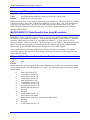
MS{anynode},MI4
Station Status Word (Read Only)
Range:
$000000 - $FFFFFF
Units:
Bits
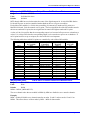
This variable, when queried, reports the value of the current status word bits for the 16-Axis MACRO
Station. The value reported should be broken into bits. Each bit reports the presence or absence of a
particular fault on the Station. If the bit is 0, the fault has not occurred since Station faults were last
cleared. If the bit is 1, the fault has occurred since Station faults were last cleared.
BITn
0
1
2
3
4
5
6
7
8
9
10
11
12
13
14
15
16
17
18
19
20
21
22
23
Fault Description
CPU – Fault (No MACRO IC #1 detected)
Ring Error - Temporary
Ring Break
Station Fault - Station Shutdown
Ring Fault - Any permanent Ring fault
Spare
Amplifier Fault
Ring Break Received
Spare
Spare
Spare
Spare
Ring Active
Spare
Detected a MACRO or SERVO IC configuration change or SW1 change from last save.
Detected UBUS SERVO IC #7 Attached to MACRO IC #0 & 1 (2 channels each)
Detected UBUS SERVO IC #6 Attached to MACRO IC #1
Detected UBUS SERVO IC #5 Attached to MACRO IC #0
Detected UBUS SERVO IC #4 Attached to MACRO IC #1
Detected UBUS SERVO IC #3 Attached to MACRO IC #1
Detected UBUS SERVO IC #2 Attached to MACRO IC #0
Detected UBUS SERVO IC #1 Attached to MACRO IC #0
Detected CPU MACRO IC #1 ($C0C0)
Detected CPU MACRO IC #0 ($C080)
Any of the fault bits that are set can be cleared with the MSCLRF{anynode} (clear fault) command, or
the MS$$${anynode} (Station reset) command.
2
16-Axis MACRO Station MI-Variable Reference
16-Axis MACRO CPU Software Reference Manual
MS{anynode},MI5
Ring Error Counter
Range:
$000000 - $FFFFFF
Units:
Error Count
This variable, when queried, reports the number of ring communications errors detected by the 16-Axis
MACRO Station since the most recent power-up or reset.
Note:
It is possible to write a value to this variable, but this should not be done if you are
using MI6
The ring error counter value can be cleared to zero using the or MS$$${anynode} commands.
MS{anynode},MI6
Maximum Permitted Ring Errors in One Second
Range:
$0000000 - $FFFFFFF
Units:
Errors per second
Default:
This variable sets the maximum number of ring errors that can be detected by the 16-Axis MACRO
Station in a one second period without causing it to shut down for ring failure.
MS{anynode},MI7
Range:
Units:
Default:
(Reserved for future use)
0
none
0
MS{anynode},MI8
MACRO Ring Check Period
Range:
0 - 255
Units:
Station phase cycles
Default:
8
MI8 determines the period, in phase cycles, for the 16-Axis MACRO Station to evaluate whether there
has been a MACRO ring failure or not. Every phase cycle, the Station checks the ring communications
status. In MI8 phase cycles (or MACRO ring cycles), the Station must receive at least MI10 “sync
packets” and detect fewer than MI9 ring communications errors, to conclude that the ring is operating
correctly. Otherwise, it will conclude that the ring is not operating properly, set its servo command output
values to zero, set its amplifier enable outputs to the “disable” state, and force all of its digital outputs to
their “shutdown” state as defined by I72-I89, and report a ring fault.
If MI8 is set to 0 at power-on/reset, the 16-Axis MACRO Station will automatically set it to 8.
MS{anynode},MI9
MACRO Ring Error Shutdown Count
Range:
0 - 255
Units:
none
Default:
4
MI9 determines the number of MACRO communications errors detected that will cause a shutdown fault
of the 16-Axis MACRO Station. If the Station detects MI9 or greater MACRO communications errors in
MI8 phase (MACRO ring) cycles, it will shut down on a MACRO communications fault, turning off all
outputs.
The Station can detect one ring communications error per phase cycle. Setting MI9 greater than MI8
means that the Station will never shut down for ring communications error.
16-Axis MACRO Station MI-Variable Reference
3
16-Axis MACRO CPU Software Reference Manual
The Station can detect four types of communications errors: byte violation errors, packet checksum errors,
packet overrun errors, and packet under run errors. If MI9 errors have occurred in the MI8 check period,
and at least half of these errors are byte “violation” errors, the Station will conclude that there is a ring
break immediately upstream of it (if there are no ring input communications to the Station, there will be
continual byte violation errors). In this case, not only will it set its servo command output values to zero,
set its amplifier enable outputs to the “disable” state, and force all of its digital outputs to their
“shutdown” state as defined by I72-I89, but it will also turn itself into a master so it can report to other
devices downstream on the ring.
If MI9 is set to 0 at power-on/reset, the 16-Axis MACRO Station will automatically set it to 4.
MS{anynode},MI10
MACRO Sync Packet Shutdown Count
Range:
0 – 65,535
Units:
none
Default:
4
MI10 determines the number of MACRO ring “sync packets” that must be received during a check period
for the Station to consider the ring to be working properly. If the Station detects fewer than MI10 sync
packets in MI8 phase (MACRO ring) cycles, it will shut down on a MACRO communications fault,
setting its servo command output values to zero, setting its amplifier enable outputs to the “disable” state,
and forcing all of its digital outputs to their shutdown state as defined by I72-I89.
The node number (0-15) of the sync packet is determined by bits 16-19 of Station variable MI996. On the
16-Axis MACRO Station, this is always node 15 ($F), because this node is always active for MACRO
Type 1 auxiliary communications.
The Station checks each phase cycle to see if a sync packet has been received or not. Setting MI10 to 0
means the Station will never shut down for lack of sync packets. Setting MI10 greater than MI8 means
that the Station will always shut down for lack of sync packets.
If MI10 is set to 0 at power-on/reset, the 16-Axis MACRO Station will automatically set it to 4.
MS{anynode},MI11
Station Order Number
Range:
0 – 254
Units:
none
Default:
0
MI11 contains the station-order number of the 16-Axis MACRO Station on the ring. This permits it to
respond to auxiliary MACROSTASCII<n=Station Order Number> commands from a Turbo PMAC ring
controller, regardless of the 16-Axis MACRO Station’s rotary-switch settings.
The station ordering scheme permits the ring controller to isolate each master or slave station on the ring
in sequence and communicate with it, without knowing in advance how the ring is configured or whether
there are any conflicts in the regular addressing scheme. This is very useful for the initial setup and
debugging of the ring configuration.
Normally, station order numbers of devices on the ring are assigned in numerical order, with the station
downstream of the ring controller getting station-order number 1. This does not have to be the case,
however.
Unordered stations have the station-order number 0. When the ring controller executes a
MACROSTASCII255 command, the first unordered station in the ring will respond.
MI11 can also be set with the ASCII command STN={constant}. The value of MI11 can also be
queried with the ASCII command STN.
4
16-Axis MACRO Station MI-Variable Reference
16-Axis MACRO CPU Software Reference Manual
MS{anynode},MI12
Card Identification
Range:
0 – $FFFFFF
Units:
none
Default:
$936747 (603719)
This returns the card part number. The same as the CID ASCII command.
MS{anynode},MI13
Display Enable and Type
Range:
0–3
Units:
none
Default:
0
0 = No Display output
1 = LCD Display Output
3 = Vacuum Display Output
MS{anynode},MI14
MACRO IC Source of Phase Clock
Range:
0–1
Units:
none
Default:
1
Default MACRO #1 is the default source of the Phase clock. Setting MI14 = 0, sets MACRO IC #0 as
the source of the Phase clock. Normally the second MACRO IC #1 receives its node information after
MACRO IC #0, so it should be the source of the phase clock. This insures that both MACRO ICs receive
the ring node data before a phase interrupt is generated.
MS{anynode},MI15
Enable MACRO Plcc
Range:
0-1
Units:
none
Default:
0
MI15 enables and disables the PLCCs running in the 16-Axis MACRO CPU.
MACRO IC Global Channel Status Setup MI-Variables
Each MACRO IC (0 and 1) has its own set of these variables. Therefore, they are accessed through their
MACRO IC. For example, MS0,MI16 accesses MACRO IC 0’s MI16 and MS16,MI16 accesses
MACRO IC 1’s MI16. MACRO IC 1’s variables can be accessed can be accessed through MACRO IC 0
by adding 1000 to the MI variable. For example, MS0,MI1016 accesses MACRO IC 1’s MI16
MS{anynode},MI16
Encoder-Fault Reporting Control
Range:
0-1
Units:
none
Default:
0
MI16 permits the user to control which type of encoder error is reported back to PMAC in the channel
status flag word for each servo interface channel.
If MI16 is set to 0 (default), then the encoder count-error status bit (bit 8 in the channel hardware status
word) for each encoder channel is copied into bit 8 of the matching node’s status flag word for
transmission back to the PMAC. An encoder count error is reported when both A and B encoder signals
have a transition in the same SCLK hardware sampling cycle.
16-Axis MACRO Station MI-Variable Reference
5
16-Axis MACRO CPU Software Reference Manual
If MI16 is set to 1, then the ASIC’s own encoder-loss status bit (bit 7 in the channel hardware status
word) for each encoder channel is copied into bit 8 of the matching node’s status flag word for
transmission back to the PMAC. Note that this reporting function is unrelated to the automatic encoderloss shutdown function using external circuitry that can be enabled with MI7 and reported in MI4.
In order for this encoder-loss detection to work properly, several conditions must apply:
• A B version or newer of the DSPGATE1/2 Servo/MACRO IC must be used (true on boards built
since Spring 1998).
• Differential encoders must be used.
• The A+, A-, B+, and B- encoder signals must be wired into the T, U, V, and W supplemental flag
inputs, respectively, as well as into the regular encoder lines.
• The socketed resistor SIP packs for the encoder channels must be reversed from their factory default
configuration. These SIP packs are installed at the factory so that pin 1 of the pack – marked with a
dot – is installed in pin 1 of the socket – marked with a bold white outline and a square solder pin on
the board. For this encoder-loss to work, the SIP-pack for each encoder must be reversed so that it is
at the opposite end of the socket. The SIP packs are:
Board
Encoder 1
Encoder 2
Encoder 3
ACC-24E2
RP22
RP24
RP22*
ACC-24E2A
RP22
RP24
RP22*
ACC-24E2S
RP19
RP21
RP27
*Resistor packs on Option 1 top board of 2-board assembly
•
Encoder 4
RP24*
RP24*
RP29
MI16 must be set to 1.
If the T, U, V, and W input flags are used for different purposes, such as Hall commutation sensors, or
sub-count information from an analog encoder interpolator, the state of the encoder-loss status bit would
appear random and arbitrary.
The state of the encoder-loss hardware status bit for a channel can be polled with MI927 for the node
mapped to the channel. If it has been set, it can be cleared by writing a 0 value to MI927.
Note:
As long as the socketed resistor pack for an encoder is reversed from the factory
default configuration, the 16-Axis MACRO Station will be able to detect
differential encoder loss and shut down on it, even without wiring the encoder
signals into T, U, V, and W. However, unless the signals are wired into these flag
lines and MI16 is set to 1, the 16-Axis MACRO Station will not be able to notify
PMAC exactly which encoder sustained the loss.
MS{anynode},MI17
Amplifier Fault Disable Control
Range:
$00 - $FF
Units:
none
Default:
$00 (amplifier function enabled for all axes)
This variable controls whether the amplifier input to the machine interface channel mapped to each servo
node by SW1 is used as one of the conditions that creates a node fault to be sent back to the PMAC over
the MACRO ring.
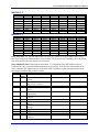
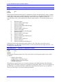
The variable consists of eight bits; each bit controls the disabling of the amplifier fault input for one of the
nodes on the Station. A 0 in the bit specifies that the amplifier fault input is to be used (enabled); a 1 in
the bit specifies that the amplifier fault input is not to be used (disabled). The corresponding bit of MI18
determines the polarity of the input if it is enabled.
6
16-Axis MACRO Station MI-Variable Reference
16-Axis MACRO CPU Software Reference Manual
The following table shows the relationship between the bits of MI17 and the servo nodes on the Station:
7
13
MI17 Bit #
Node #
MS{anynode},MI18
6
12
5
9
4
8
3
5
2
4
1
1
0
0
Amplifier Fault Polarity
Range:
$00 - $FF
Units:
none
Default:
$00 (low-true fault for all nodes)
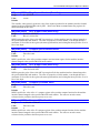
This variable controls how the 16-Axis MACRO Station interprets the polarity of the amplifier fault
inputs for each servo node. The variable consists of eight bits; each bit controls the polarity for one of the
servo nodes on the Station. A 0 in a bit specifies a low-true fault (low voltage input means fault); a 1 in a
bit specifies a high-true fault (high voltage input means fault). A bit of MI18 is only used if the
corresponding bit of MI17 is set to 0, enabling the amplifier fault function for that node.
The following table shows the relationship between the bits of MI18 and the servo nodes on the Station:
MI18 Bit #
Node #
7
13
6
12
5
9
4
8
3
5
2
4
1
1
0
0
Global I/O Transfer MI-Variables
MS{anynode},MI19
I/O Data Transfer Period
Range:
0 - 255
Units:
Phase Clock Cycles
Default:
0
MI19 controls the data transfer period on a 16-Axis MACRO Station between the MACRO node interface
registers and the I/O registers, as specified by station MI-variables MI20 through MI71, and MI169
through MI172. If MI19 is set to 0, this data transfer is disabled. If MI19 is greater than 0, its value sets
the period in Phase clock cycles (the same as MACRO communications cycles) at which the transfer is
done.
MS{anynode},MI20
Data Transfer Enable Mask
Range:
$000000000000 - $FFFFFFFFFFFF
Units:
Bits
Default:
0
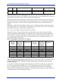
MI20 controls which of 48 possible data transfer operations are performed at the data transfer period set
by MI19. MI20 is a 48-bit value; each bit controls whether the data transfer specified by one of the
variables MI21 through MI68 is performed. The relationship of MI20 bits to MI21-MI68 transfers is
explained in the following table.
16-Axis MACRO Station MI-Variable Reference
7
16-Axis MACRO CPU Software Reference Manual
MI20 Bit #
Bit
Value
TransferControl
MI-Variable
MI20 Bit #
Bit Value
TransferControl
MI-Variable
0
1
2
3
4
5
6
7
8
9
10
11
12
13
14
15
16
17
18
19
20
21
22
23
$1
$2
$4
$8
$10
$20
$40
$80
$100
$200
$400
$800
$1000
$2000
$4000
$8000
$10000
$20000
$40000
$80000
$100000
$200000
$400000
$800000
MI21
MI22
MI23
MI24
MI25
MI26
MI27
MI28
MI29
MI30
MI31
MI32
MI33
MI34
MI35
MI36
MI37
MI38
MI39
MI40
MI41
MI42
MI43
MI44
24
25
26
27
28
29
30
31
32
33
34
35
36
37
38
39
40
41
42
43
44
45
46
47
$1000000
$2000000
$4000000
$8000000
$10000000
$20000000
$40000000
$80000000
$100000000
$200000000
$400000000
$800000000
$1000000000
$2000000000
$4000000000
$8000000000
$10000000000
$20000000000
$40000000000
$80000000000
$100000000000
$200000000000
$400000000000
$800000000000
MI45
MI46
MI47
MI48
MI49
MI50
MI51
MI52
MI53
MI54
MI55
MI56
MI57
MI58
MI59
MI60
MI61
MI62
MI63
MI64
MI65
MI66
MI67
MI68
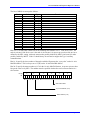
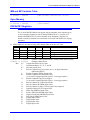
MS{anynode},MI21-MI68 Data Transfer Source and Destination Address
Range:
$000000000000 - $FFFFFFFFFFFF
Units:
Double 16-Axis MACRO Station Addresses
Default:
0
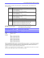
These MI-variables each specify a data transfer (copying) operation that will occur on the 16-Axis
MACRO Station at a rate specified by Station Variable MI19, and enabled by Station variable MI20.
Each variable specifies the address from which the data will be copied (read), and the address to which
the data will be copied (written). These variables are 48-bit values, usually specified as 12 hexadecimal
digits.
The first 24 bits (6 hex digits) specify the address of the register on the 16-Axis MACRO Station from
which the data is to be copied; the second 24 bits (six hex digits) specify the address on the 16-Axis
MACRO Station to which the data is to be copied. In each set of six hex digits, the last four hex digits
specify the actual address. The first two digits (eight bits) specify what portion of the address is to be
used.
The following diagram shows what each digit represents:
Hex Digit #
Contents
8
1
2
From
Register
Format
Code
3
4
5
6
From Register Address
7
8
To
Register
Format
Code
9
10
11
12
To Register Address
16-Axis MACRO Station MI-Variable Reference
16-Axis MACRO CPU Software Reference Manual
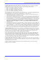
The following table shows the 2-digit hex format codes and the portions of the address that each one
selects.
Code
X or Y
$40
$48
$50
$54
$60
$64
$6C
$78
$7E
Y
Y
Y
Y
Y
Y
Y
Y
NA
Bit Width Bit Range
8
8
8
12
12
16
16
24
NA
0-7
8-15
16-23
0-11
12-23
0-15
8-23
0-23
NA
$B0
$B8
$C0
$C4
$D0
$D4
$DC
$E8
X
X
X
X
X
X
X
X
8
8
8
12
12
16
16
24
0-7
8-15
16-23
0-11
12-23
0-15
8-23
0-23
Notes
Lower 12-bit ADC registers
Upper 12-bit ADC registers
16-bit MACRO Servo Node Registers
24-bit MACRO Servo Node Registers
Use the MM variable definition for the
decode of the variable and address and the
address being the MM variable number.
16-bit MACRO I/O Node Registers
24-bit MACRO I/O Node Registers
The memory and I/O map at the back of this Software Reference manual provides a detailed list of
registers that can be copied using these MI-variables.
Note:
For copying data between digital I/O cards with byte-wide data paths (ACC-9E,
10E, 11E, 12E, 14E, 65E, 66E, 67E and 68E) and MACRO nodes, it is generally
better to use MI69 – MI71, and MI169 – MI172.
Example:
MI21=$780200E8C0A0
copies 24-bit data from Station address Y:$0200 to X:$C0A0
MI21=$7E00027E0003
copies MM2 into MM3 ( MM3 = MM2)
MACRO IC I/O Transfer MI-Variables
Each MACRO IC (0 and 1) has its own set of these variables. Therefore, they are accessed through their
MACRO IC. For example, MS0,MI69 accesses MACRO IC 0’s MI69 and MS16,MI69 accesses
MACRO IC 1’s MI69. MACRO IC 1’s variables can be accessed can be accessed through MACRO IC 0
by adding 1000 to the MI variable. For example, MS0,MI1069 accesses MACRO IC 1’s MI69.
MS{anynode},MI69, MI70
I/O-Board 16-Bit Transfer Control
Range:
$000000000000 - $FFFFFFFFFFFF
Units:
Extended addresses
Default:
0
MI69 and MI70 specify the registers used in 16-bit I/O transfers between MACRO node interface
registers and I/O registers on the 9E, 10E, 11E, 12E, 14E, 65E, 66E, 67E, and ACC-68E I/O boards on a
16-Axis MACRO Station. They are used only if MI19 is greater than 0.
16-Axis MACRO Station MI-Variable Reference
9
16-Axis MACRO CPU Software Reference Manual
MI69 and MI70 are 48-bit variables represented as 12 hexadecimal digits. The first six digits specify the
number and address of 48-bit (3 x 16) real-time MACRO-node register sets to be used. The second six
digits specify the number and address of 16-bit I/O sets on an UMAC IO board to be used. The
individual digits are specified as follows:
Digit #
1
2
3-6
Possible Values
0, 1, 2, 3
7
0
$C0A1 (Node 2), $C0A5 (Node 3),
$C0A9 (Node 6), $C0AD (Node 7),
$C0B1 (Node 10), $C0B5 (Node 11)
0, 1, 2, 3
8
1
9-12
$8800, $8840
$8880, $88C0
Description
Number of MACRO I/O nodes to use (0 disables); this
should also match the number of 48-bit I/O sets you
intend to use (see Digit 7)
(Reserved for future use)
MACRO Station X Address of MACRO I/O node first
of three 16-bit registers
Number of 16-bit I/O sets to use (1x16, 2x16, 3x16; 0
disables)
Set to 1 for ACC-14E, ACC-65E, ACC-66E, ACC-67E
consecutive address read (Base, +$1000, +$2000)
MACRO Station Y Base Address of UMAC IO Card
When this function is active, the 16-Axis MACRO Station will copy values from the MACRO command
(input) node registers to the I/O board addresses; it will copy values from the I/O board addresses to the
MACRO feedback (output) node registers. Writing a ‘0’ to a bit of the I/O board enables it as an input,
letting the output pull high. Writing a ‘1’ to a bit of the I/O board enables it as an output and pulls the
output low.
The following table shows the mapping of I/O points on the I/O backplane boards to the MACRO node
registers:
Board # at
Set
Address
E6x Rows
Connected
Byte on
Data Bus
1st
1&2
Low
1st
1&2
Low
1st
1&2
Low
2nd
2 & 3*
Middle
2nd
2 & 3*
Middle
2nd
2 & 3*
Middle
3rd
4&5
High
3rd
4&5
High
3rd
4&5
High
* Rows 3 & 4 connected creates same setting
I/O Point
#s on
Board
Matching MACRO X Register
0 –15
16 – 31
32 - 47
0 –15
16 – 31
32 - 47
0 –15
16 – 31
32 - 47
Specified MACRO X Address + 0
Specified MACRO X Address + 1
Specified MACRO X Address + 2
Specified MACRO X Address + 4
Specified MACRO X Address + 5
Specified MACRO X Address + 6
Specified MACRO X Address + 8
Specified MACRO X Address + 9
Specified MACRO X Address + 10
Examples:
MI69=$30C0A1308800 transfers three sets of 48-bit I/O between an I/O board set at $8800 and
MACRO Nodes 2 ($C0A1-$C0A3), 3 ($C0A5-$C0A7), and 6 ($C0A9-$C0AB).
MI70=$10C0B1308840 transfers one set of 48-bit I/O between an I/O board set at $8840 and MACRO
Node 10 ($C0B1-$C0B3).
10
16-Axis MACRO Station MI-Variable Reference
16-Axis MACRO CPU Software Reference Manual
MS{anynode},MI71
I/O-Board 24-Bit Transfer Control
Range:
$000000000000 - $FFFFFFFFFFFF
Units:
Extended addresses
Default:
0
MI71 specifies the registers used in 24-bit I/O transfers between MACRO I/O node interface registers and
I/O registers on the 9E, 10E, 11E, 12E, 14E, 65E, 66E, 67E, and 68E I/O boards on a 16-Axis MACRO
Station. It is only used if MI19 is greater than 0.
MI71 is a 48-bit variable represented as 12 hexadecimal digits. The first six digits specify the number
and address of 48-bit real-time MACRO-node register sets to be used. The second six digits specify the
number and address of 48-bit I/O sets on an UMAC IO board to be used. The individual digits are
specified as follows:
Digit #
1
Possible Values
Description
0, 1, 2, 3
2
3-6
7
0
$C0A0 (Node 2), $C0A4 (Node 3),
$C0A8 (Node 6), $C0AC (Node 7),
$C0B0 (Node 10), $C0B4 (Node
11)
0, 1, 2
8
1
9-12
$8800, $8840
$8880, $88C0
Number of MACRO I/O nodes to use times 2 (0
disables); this should also match the number of 48-bit
I/O sets you intend to use (see Digit 7)
(Reserved for future use)
MACRO Station X Address of MACRO I/O node first
of three 16-bit registers
Number of 24-bit I/O sets to use (1x24, 2x24; 0
disables)
Set to 1 for ACC-14E, ACC-65E, ACC-66E, ACC-67E
consecutive address read (Base, +$1000, +$2000)
MACRO Station Y Base Address of UMAC IO card
When this function is active, the 16-Axis MACRO Station will copy values from the MACRO command
(input) node registers to the I/O board addresses; it will copy values from the I/O board addresses to the
MACRO feedback (output) node registers. Writing a ‘0’ to a bit of the I/O board enables it as an input,
letting the output pull high. Writing a ‘1’ to a bit of the I/O board enables it as an output and pulls the
output low.
The following table shows the mapping of I/O points on the I/O backplane boards to the MACRO node
registers:
Board # at
Set
Address
E6x Rows
Connected
Byte on
Data Bus
1st
1&2
Low
1st
1&2
Low
2nd
2 & 3*
Middle
2nd
2 & 3*
Middle
3rd
4&5
High
3rd
4&5
High
* Rows 3 and 4 connected creates same setting
16-Axis MACRO Station MI-Variable Reference
I/O Point
#s on
Board
Matching MACRO X Register
0 –23
24 – 47
0 –23
24 – 47
0 –23
24 – 47
Specified MACRO X Address + 0
Specified MACRO X Address + 4
Specified MACRO X Address + 8
Specified MACRO X Address + 12
Specified MACRO X Address + 16
Specified MACRO X Address + 20
11
16-Axis MACRO CPU Software Reference Manual
MS{anynode},MI72-MI89
Output Power-On/Shutdown State
Range:
$000000 - $FFFFFF
Units:
Individual bit values
Default:
$000000
MI72 through MI89 are used to determine the states of the digital outputs for 16-Axis MACRO Station
I/O boards at power-on and on controlled station shutdown due to a ring error condition.
Each of these MI-variables is a 24-bit value controlling 24 consecutively numbered I/O points on a
MACRO I/O board. Each bit controls one I/O point. The least significant bit of the MI-variable controls
the lowest-numbered I/O point; the most significant bit controls the highest-numbered I/O point.
A value of 0 in a bit specifies that the corresponding output is to be turned off at power-on or shutdown; a
value of 1 in a bit specifies that the corresponding output is to be turned on at power-on or shutdown. If
an I/O point has been set up as an input, the value of the bit is not important.
The following table shows which I/O points are controlled by each of these MI-variables
Variable
Board Addressed
by Variable
I/O Points
Controlled
ACC-3E Option
Required
Present on
ACC-4E?
MI72
MI73
MI74
MI75
MI76
MI77
MI78
MI79
MI80
MI81
MI82
MI83
MI84
MI85
MI86
MI87
MI88
MI89
MI69
MI69
MI69
MI69
MI69
MI69
MI70
MI70
MI70
MI70
MI70
MI70
MI71
MI71
MI71
MI71
MI71
MI71
I/O00 – I/O23
I/O24 – I/O47
I/O48 – I/O71
I/O72 – I/O95
I/O96 – I/O119
I/O120 – I/O143
I/O00 – I/O23
I/O24 – I/O47
I/O48 – I/O71
I/O72 – I/O95
I/O96 – I/O119
I/O120 – I/O143
I/O00 – I/O23
I/O24 – I/O47
I/O48 – I/O71
I/O72 – I/O95
I/O96 – I/O119
I/O120 – I/O143
Option A
Option A
Option B
Option B
Option C
Option C
Option A
Option A
Option B
Option B
Option C
Option C
Option A
Option A
Option B
Option B
Option C
Option C
Yes
Yes
No
No
No
No
Yes
Yes
No
No
No
No
Yes
Yes
No
No
No
No
MS{anynode},MI90
Y:MTR Servo Channel Disable and MI996 Enable
Range:
$00 - $3333
Units:
None
Default:
$0000
MI996 = MI996 | (MI90 & $3333)
The servo channel nodes that are enabled in MI996 by MI90 are disabled as servo transfer channels.
Example:
MI90 = $3000 will disable servo channel transfers on nodes 12 and 13 and sets nodes 12 and 13 on
MI996. This allows the use of these nodes by MI91 – MI98 for data transfer.
12
16-Axis MACRO Station MI-Variable Reference
16-Axis MACRO CPU Software Reference Manual
MS{anynode},MI91 - MI98
Range:
Units:
Phase Interrupt 24 Bit Data Copy
$00000000 - $FFFFFFFF
Individual bits
Hex Digit #
Contents
1
2
From $00
= Y: 24bit
$80 = X:
24bit
MS{anynode},MI99
Range:
Units:
Default:
3
4
5
6
From Register Address
7
8
To $00 =
Y: 24bit
$80 = X:
24bit
9
10
11
12
To Register Address
(Reserved for Future Use)
0
0
MACRO IC Position Processing MI-Variables
Each MACRO IC (0 and 1) has its own set of these variables. Therefore, they are accessed through their
MACRO IC. For example, MS0,MI101 accesses MACRO IC 0’s MI101 and MS16,MI101 accesses
MACRO IC 1’s MI101. MACRO IC 1’s variables can be accessed can be accessed through MACRO IC
0 by adding 1000 to the MI variable. For example, MS0,MI1101 accesses MACRO IC 1’s MI101.
MS{anynode},MI101-MI108
Ongoing Position Source Address
Range:
$0000 - $FFFF
Units:
16-Axis MACRO Station “X” Addresses
Default MACRO IC 0:
MI101 (1st motor node: Node 0):
MI102 (2nd motor node: Node 1):
MI103 (3rd motor node: Node 4):
MI104 (4th motor node: Node 5):
MI105 (5th motor node: Node 8):
MI106 (6th motor node: Node 9):
MI107 (7th motor node: Node 12):
MI108 (8th motor node: Node 13):
$0010
$0011
$0012
$0013
$0014
$0015
$0016
$0017
{1st line of encoder conversion table}
{2nd line of encoder conversion table}
{3rd line of encoder conversion table}
{4th line of encoder conversion table}
{5th line of encoder conversion table}
{6th line of encoder conversion table}
{7th line of encoder conversion table}
{8th line of encoder conversion table}
$0090
$0091
$0092
$0093
$0094
$0095
$0096
$0097
{1st line of encoder conversion table}
{2nd line of encoder conversion table}
{3rd line of encoder conversion table}
{4th line of encoder conversion table}
{5th line of encoder conversion table}
{6th line of encoder conversion table}
{7th line of encoder conversion table}
{8th line of encoder conversion table}
Default MACRO IC 1:
MI101 (1st motor node: Node 0):
MI102 (2nd motor node: Node 1):
MI103 (3rd motor node: Node 4):
MI104 (4th motor node: Node 5):
MI105 (5th motor node: Node 8):
MI106 (6th motor node: Node 9):
MI107 (7th motor node: Node 12):
MI108 (8th motor node: Node 13):
MI101 through MI108 (MI10x) determine what registers are used for feedback for the eight possible
motor nodes (MI10x controls the xth motor node, which usually corresponds to Motor x on PMAC) on a
16-Axis MACRO Station.
For each active motor node, the value in the specified register is copied into the 24-bit position feedback
MACRO register. Typically, the addresses specified are those from the 16-Axis MACRO Station’s
encoder conversion table, at Station registers X:$0010 to X:$002F, corresponding to Station MI-variables
MI120 to MI151, respectively.
16-Axis MACRO Station MI-Variable Reference
13
16-Axis MACRO CPU Software Reference Manual
MS{anynode},MI109 - MI110
(Reserved for Future Use)
MS{anynode},MI111-MI118
Power-Up Position Source Address
Range:
Units:
Default:
$000000 - $FFFFFF
Extended 16-Axis MACRO Station Addresses
0
MI111 (1st motor node: Node 0)
MI112 (2nd motor node: Node 1)
MI113 (3rd motor node: Node 4)
MI114 (4th motor node: Node 5)
MI115 (5th motor node: Node 8)
MI116 (6th motor node: Node 9)
MI117 (7th motor node: Node 12)
MI118 (8th motor node: Node 13)
MI111 through MI118 (MI11x) specify whether, where, and how absolute position is to be read on the
16-Axis MACRO Station for a motor node (MI11x controls the xth motor node, which usually
corresponds to Motor x on PMAC) and sent back to the PMAC or PMAC2.
If MI11x is set to 0, no power-on/reset absolute position value will be returned to PMAC. If MI11x is set
to a value greater than 0, then when the PMAC requests the absolute position because its Ix10 and/or Ix81
values are set to obtain absolute position through MACRO (sending an auxiliary MS{node},MI920 or
MS{node},MI930 command), the 16-Axis MACRO Station will use MI11x to determine how to read
the absolute position, and report that position back to PMAC as an auxiliary response.
MI11x consists of two parts. The low 16 bits (last four hexadecimal digits) specify the address on the 16axis MACRO Station from which the absolute position information is read. The high eight bits (first two
hexadecimal digits) tell the 16-axis MACRO Station how to interpret the data at that address (the method.
The following table shows the possible values for MI11x, organized by the first two digits:
MI11n Bits
16-23 for
Unsigned
(Signed)
$00-$07
($80-$87)
Resolver-to-Digital Converter
$08-$18
($88-$98)
$17-$2A
($97-$AA)
$2B ($AB)
Single-Y-Word Parallel (8 to 24
bits)
Double-Y-Word Parallel (25 to
42 bits)
Double-Byte Parallel (16 bits) in
low bytes of 24-bit words
Double-Byte Parallel (16 bits) in
middle bytes of 24-bit words
Double-Byte Parallel (16 bits) in
middle bytes of 24-bit words
Triple-Byte Parallel (24 bits) in
low bytes of 24-bit words
$2C ($AC)
$2D ($AD)
$2E ($AE)
$2F ($AF)
14
Type of Feedback
Triple-Byte Parallel (24 bits) in
middle bytes of 24-bit words
Notes
Used for ACC-8D Opt 7 connected to CPU board
JTHW connector; address is multiplexer port
address ($00 - $FF)
Used for MDLT feedback;
Value in B16-21 is number of bits to read
Value in B16-21 is number of bits; most
significant bits are at {address + 1}
Used for ACC-3E parallel feedback;
Most significant byte is at {address + 1}
Used for ACC-3E parallel feedback;
Most significant byte is at {address + 1}
Used for ACC-3E parallel feedback;
Most significant byte is at {address + 1}
Used for ACC-3E parallel feedback;
Middle byte is at {address + 1};
Most significant byte is at {address + 2}
Used for ACC-3E parallel feedback;
Middle byte is at {address + 1};
Most significant byte is at {address + 2}
16-Axis MACRO Station MI-Variable Reference
16-Axis MACRO CPU Software Reference Manual
$30 ($B0)
Triple-Byte Parallel (24 bits) in
middle bytes of 24-bit words
$31 ($B1)
16-Bit Parallel in high 16 bits of
24 bit word
Double 13-Bit Parallel
12-Bit Parallel in high 12 bits of
24-bit word
Single-X-Word Parallel (8 to 24
bits)
Double-X-Word Parallel (25 to
42 bits)
Yaskawa Absolute Encoder
Converter thru Multiplexer Port
$32 ($B2)
$33 ($B3)
$48-$56
($C8-$D6)
$57-$6A
($D7-$EA)
$71 ($F1)
$72 ($F2)
Yaskawa Absolute Encoder
Converter thru RS-232 interface
Used for ACC-3E parallel feedback;
Middle byte is at {address + 1};
Most significant byte is at {address + 2}
Used for ACC-28B A/D converter feedback
Used for Sanyo Absolute Encoder Interface
Used for ACC-1E-B2 or ACC-6E A/D converter
feedback
Value in B16-23 is number of bits to read
Value in B16-23 is number of bits; most
significant bits are at {address + 1}
Used for ACC-8D Opt 9 connected to CPU board
JTHW port; address is multiplexer port address
($00 - $FF)
Used for ACC-8D Opt 9 connected to CPU board
serial port.
If Bit 23 of MI11x is set to 1 (providing the value for Bits 16-23 shown in parentheses), then the position
value read is sign extended to produce a signed position value. If Bit 23 is set to 0, no sign extension is
performed, producing an unsigned positive position value. Bit 23 of PMAC’s Ix10 for the motor using
this MACRO node must be the same as Bit 23 of the Station’s MI11x.
MS{anynode},MI119
(Reserved for Future Use)
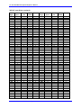
MS{anynode},MI120-MI151
Encoder Conversion Table Entries
Range:
$000000 - $FFFFFF
Units:
Extended 16-Axis MACRO Station Addresses
Default:
(dependent on SW1 setting)
MI120 through MI151 form the 32-setup lines of the 16-axis MACRO Station’s Encoder Conversion
Table (ECT). The Encoder Conversion Table on the Station is similar in concept to that of the PMAC or
PMAC2 itself; it is identical in structure to the Encoder Conversion Table of the Turbo PMAC. The 16axis MACRO Station’s table is executed every ring cycle to prepare the feedback data to be sent back to
the PMAC over the MACRO ring, where it will likely be passed through the PMAC’s own table.
The ECT consists of a series of entries with each entry processing one feedback value. An entry in the
ECT can have one, two, or three lines, therefore one, two, or three of these 24-bit MI-variables. Each MIvariable occupies a fixed register in the 16-axis MACRO Station’s memory map. The register addresses
are important, because the results of the ECT are accessed by address.
Table Addresses: The following table shows the Station Y-address for each of the MI-variables in the
table. The processed feedback value for an entry resides in the X-register of the same address as the last
line of the entry. Variable MI10x for the xth motor node on the Station should contain the address of this
X-register for the feedback it wants to send back to PMAC over the MACRO ring.
16-Axis MACRO Station MI-Variable Reference
15
16-Axis MACRO CPU Software Reference Manual
MACRO IC 0
MI-Var.
Address
MI-Var.
Address
MI-Var.
Address
MI-Var.
Address
MI120
MI121
MI122
MI123
MI124
MI125
MI126
MI127
$0010
$0011
$0012
$0013
$0014
$0015
$0016
$0017
MI128
MI129
MI130
MI131
MI132
MI133
MI134
MI135
$0018
$0019
$001A
$001B
$001C
$001D
$001E
$001F
MI136
MI137
MI138
MI139
MI140
MI141
MI142
MI143
$0020
$0021
$0022
$0023
$0024
$0025
$0026
$0027
MI144
MI145
MI146
MI147
MI148
MI149
MI150
MI151
$0028
$0029
$002A
$002B
$002C
$002D
$002E
$002F
MI-Var.
Address
MI-Var.
Address
MI-Var.
Address
MI-Var.
Address
MI120
MI121
MI122
MI123
MI124
MI125
MI126
MI127
$0090
$0091
$0092
$0093
$0094
$0095
$0096
$0097
MI128
MI129
MI130
MI131
MI132
MI133
MI134
MI135
$0098
$0099
$009A
$009B
$009C
$009D
$009E
$009F
MI136
MI137
MI138
MI139
MI140
MI141
MI142
MI143
$00A0
$00A1
$00A2
$00A3
$00A4
$00A5
$00A6
$00A7
MI144
MI145
MI146
MI147
MI148
MI149
MI150
MI151
$00A8
$00A9
$00AA
$00AB
$00AC
$00AD
$00AE
$00AF
MACRO IC 1
Entry First Line: The first line (MI-variable) in each entry consists of a source address in the low 16
bits, which contains the Station address of the raw data to be processed, and a method value in the high 8
bits, which specifies how this data is to be processed.
Entry Additional Lines: Depending on the method, 1 or 2 additional lines (MI-variables) may be
required in the entry to provide further instructions on processing. If the first line (MI-variable) in the
entry is $000000, this signifies the end of the active table, regardless of what subsequent entries in the
table (higher numbered MI-variables) contain.
Method
# of
lines
Process Defined
$0x
1
$1x
1
$2x
$3x
2
3
$4x
2
$5x
2
$6x
$7x
2
3
$8x
1
$9x
$Ax
$Bx
$Cx
2
2
2
1
1/T Extension of Incremental
Encoder
ACC-28 style A/D converter
(high 16 bits, no rollover)
Parallel Y-word data, no filtering
Parallel Y-word data, with
filtering
Time Base scaled digital
differentiation
Integrated ACC-28 style A/D
converter
Parallel X-word data, no filtering
Parallel X-word data, with
filtering
Parallel Extension of Incremental
Encoder
Triggered Time Base, frozen
Triggered Time Base, running
Triggered Time Base, armed
Incremental Encoder, no
extension
16
1st Additional Line
2nd Additional Line
-
-
-
-
Bits-Used Mask
Bits-Used Mask
Max Change per Cycle
Time Base Scale Factor
-
Input Bias
-
Bits-Used Mask
Bits-Used Mask
Max Change per Cycle
-
-
Time Base Scale Factor
Time Base Scale Factor
Time Base Scale Factor
-
-
16-Axis MACRO Station MI-Variable Reference
16-Axis MACRO CPU Software Reference Manual
$Dx
3
Exponential filter of parallel data
Max Change per Cycle
$Ex
$Fx
1
3
Sum or difference of entries
High-resolution Interpolator
Address of 1st A/D
converter
Filter Gain (Inverse
Time Constant)
A/D Bias Term
Digital Incremental Encoder Entries ($0x, $Cx): These two conversion table methods utilize the
incremental encoder registers in the DSPGATE ASICs on the Station. Each method provides a processed
result with the units of (1/32) count – the low five bits are fractional data.
With the $0x method, the fractional data is computed by dividing the Time Since Last Count register by
the Time Between Last Two Counts register. This technique is known as 1/T extension, and is the most
commonly used method. It can be used with a digital incremental encoder connected directly to the
Station
With the $Cx method, the fractional data is always set to zero, which means there is no extension of the
incremental encoder count. This setting is used mainly to verify the effect of one of the 1/T extension, or
the parallel extension of an analog encoder, explained below.
The ‘x’ in the second digit is always 0 in both of these methods.
With either of these conversion methods, the source address in the low 16 bits is that of the starting
register of the machine interface channel. The addresses of the machine interface channels that can be
used, and the ECT entry MI-variables that correspond to them, are shown in the following tables. The
‘m’ is the conversion method, representing ‘0’ (Incremental Encoder-1/T interpolation extension) or ‘C’
(Incremental Encoder-no extension).
Entries for Backplane Axis Boards (ACC-24E2x)
Machine
Interface
Channel #
16-Axis
MACRO
Station Base
Address
Conversion
Table Entry
Machine
Interface
Channel #
16-Axis
MACRO
Station Base
Address
Conversion
Table Entry
1
2
3
4
5
6
7
8
$8000
$8008
$8010
$8018
$8040
$8048
$8050
$8058
$m08000
$m08008
$m08010
$m08018
$m08040
$m08048
$m08050
$m08058
9
10
11
12
13
14
15
16
$9000
$9008
$9010
$9018
$9040
$9048
$9050
$9058
$m09000
$m09008
$m09010
$m09018
$m09040
$m09048
$m09050
$m09058
These are single-line entries in the table, so the next line (MI-Variable) is the start of the next entry.
Analog Incremental Encoder Entries ($8x, $Fx): These two entries process data from analog sinewave
encoders through a Delta Tau interpolator, providing a high number of position states per line using
fractional count data.
Low Resolution: With the $8x method, the fractional data is computed by reading the five inputs at bits
19-23 of the specified address (USER, W, V, U, and T flag inputs, respectively). This technique is
known as parallel extension and can be used with an analog incremental encoder processed through
accessories for the older Macro Stack Technology. This entry will not be utilized very often since the 16Axis Macro Station is used in backplane mode only.
16-Axis MACRO Station MI-Variable Reference
17
16-Axis MACRO CPU Software Reference Manual
High Resolution: With the $Fx method, the table computes the fractional information using the A/Dconverter data from an ACC-51E high-resolution encoder interpolator, producing a value with 4096 states
per line. The entry must read both an encoder channel for the whole number of lines of the encoder, and a
pair of A/D converters to determine the location within the line, mathematically combining the values to
produce a single position value.
Encoder Channel Address: The first line of the three-line entry contains $F in the first hex digit and the
base address of the encoder channel to be read in the last four digits (bits 0 to 15). The following table
shows the possible entries for an ACC-51E in the station.
Entry First Lines for ACC-51E Backplane Interpolator Boards
ACC-51E #
1st
2nd
3rd
4th
5th
6th
7th
8th
Channel 1
Channel 2
Channel 3
Channel 4
$F08000
$F08040
$F09000
$F09040
$F0A000
$F0A040
$F0B000
$F0B040
$F08008
$F08048
$F09008
$F09048
$F0A008
$F0A048
$F0B008
$F0B048
$F08010
$F08050
$F09010
$F09050
$F0A010
$F0A050
$F0B010
$F0B050
$F08018
$F08058
$F09018
$F09058
$F0A018
$F0A058
$F0B018
$F0B058
A/D Converter Address: The second line of the entry contains the base address of the first A/D
converter to be read in the last four digits (bits 0 to 15). The second A/D converter will be read at the
next higher address. The following table shows the possible settings when the ACC-51E is used.
Entry Second Lines for ACC-51E Backplane Interpolator Boards
ACC-51E #
1st
2nd
3rd
4th
5th
6th
7th
8th
Channel 1
Channel 2
Channel 3
Channel 4
$008005
$008045
$009005
$009045
$00A005
$00A045
$00B005
$00B045
$00800D
$00804D
$00900D
$00904D
$00A00D
$00A04D
$00B00D
$00B04D
$008015
$008055
$009015
$009055
$00A015
$00A055
$00B015
$00B055
$00801D
$00805D
$00901D
$00905D
$00A01D
$00A05D
$00B01D
$00B05D
A/D Bias Term: The third line of the entry contains the bias in the A/D converter values. This line
should contain the value that the A/D converters report when they should ideally report zero. The 16Axis MACRO Station subtracts this value from both A/D readings before calculating the arctangent.
Many users will leave this value at 0, but it is particularly useful to remove the offsets of single-ended
analog encoder signals.
This line is scaled so that the maximum A/D converter reading provides the full value of the 24-bit
register (+/-223). Generally, it is set by reading the A/D converter values directly as 24-bit values,
computing the average value over a cycle or cycles, and entering this value here.
Conversion Result: The result of the conversion is placed in the X-register of the third line of the entry.
Careful attention must be paid to the scaling of this 24-bit result. The least significant bit (Bit 0) of the
result represents 1/4096 of a line of the sine/cosine encoder.
18
16-Axis MACRO Station MI-Variable Reference
16-Axis MACRO CPU Software Reference Manual
When this data is passed to a PMAC, and it reads this data for servo use with Ix03, Ix04, Ix05, or Ix93, it
expects to find data in units of 1/32 of a count. Therefore, PMAC software regards this format as
producing 128 counts per line. (The fact that the hardware counter used produces 4 counts per line is not
relevant to the actual use of this format; this fact would only be used when reading the actual hardware
counter for debugging purposes.)
Example:
This format is used to interpolate a linear scale with a 40-micron pitch (40µm/line), producing a
resolution of about 10 nanometers (40,000/4096), used as position feedback for a motor. PMAC
considers a count to be 1/128 of a line, yielding a count length of 40/128 = 0.3125 µm. To set user units
of millimeters for the axis, the axis scale factor would be:
AxisScaleFactor =
1000 µm
1mm
count
counts
*
*
= 3200
UserUnit
mm
0.3125 µm
UserUnit
ACC-28 Style A/D Entries ($1x, $5x): The A/D feedback entries read from the high 16-bits of the
specified address and shift the data right three bits so that the least significant bit of the processed result in
bit 5. Unlike the parallel feedback methods, this method will not roll over and extend the result.
This data typically comes from an ACC-28E backplane A/D board.
The $1x method processes the information directly, essentially a copying with shift. The $5x integrates
the input value as it copies and shifts it. That is, it reads the input value, shifts it right three bits, adds the
bias term in the second line, and adds this value to the previous processed result.
If the second digit ‘x’ of the entry is ‘0’, the 16-bit source value is treated as a signed quantity; if it is ‘8’,
the 16-bit value is treated as an unsigned quantity. Presently, the only A/D accessory of this format that
can interface to the 16-axis MACRO Station is the ACC-28E, which provides an unsigned value, so $18
and $58 should be used.
The following table shows the entries for ACC-28E backplane converter board ADCs. The ‘m’
represents the conversion method, either ‘1’ or ‘5’.
Entries for ACC-28E ADCs
ACC-28E
Base Address
Entry for ADC1
Entry for ADC2
Entry for ADC3
Entry for ADC4
$8800
$9800
$A800
$B800
$8840
$9840
$A840
$B840
$8880
$9880
$A880
$B880
$88C0
$98C0
$A8C0
$B8C0
$m88800
$m89800
$m8A800
$m8B800
$m88840
$m89840
$m8A840
$m8B840
$m88880
$m89880
$m8A880
$m8B880
$m888C0
$m898C0
$m8A8C0
$m8B8C0
$m88801
$m89801
$m8A801
$m8B801
$m88841
$m89841
$m8A841
$m8B841
$m88881
$m89881
$m8A881
$m8B881
$m888C1
$m898C1
$m8A8C1
$m8B8C1
$m88802
$m89802
$m8A802
$m8B802
$m88842
$m89842
$m8A842
$m8B842
$m88882
$m89882
$m8A882
$m8B882
$m888C2
$m898C2
$m8A8C2
$m8B8C2
$m88803
$m89803
$m8A803
$m8B803
$m88843
$m89843
$m8A843
$m8B843
$m88883
$m89883
$m8A883
$m8B883
$m888C3
$m898C3
$m8A8C3
$m8B8C3
16-Axis MACRO Station MI-Variable Reference
19
16-Axis MACRO CPU Software Reference Manual
Parallel Feedback Entries ($2x, $3x, $6x, $7x): The parallel feedback entries read a word from the
address specified in the low 16 bits of the first entry. The four methods in this class are:
• $2x: Y-word parallel, no filtering (2-line entry)
• $3x: Y-word parallel, with filtering (3-line entry)
• $6x: X-word parallel, no filtering (2-line entry)
• $7x: X-word parallel, with filtering (3-line entry)
The second digit in the first line of the entry, represented above by ‘x’, specifies how the parallel data at
the specified address is to be processed. Currently there are 5 valid values of ‘x’:
• x=0: Shift data so that the least significant bit of the source register as specified in the “bits used”
mask word is placed in bit 5 of the processed result.
• x=4: Read the least significant byte from the low byte of the specified address; read the middle byte
from the low byte of the (specified address + 1); read the most significant byte from the low byte of
the (specified address + 2). This is used for feedback brought in through the ACC-14E 48-I/O board.
• x=5: Read the least significant byte from the middle byte of the specified address; read the middle
byte from the middle byte of the (specified address + 1); read the most significant byte from the
middle byte of the (specified address + 2). This is used for feedback brought in through the ACC14E 48-I/O board.
• x=6: Read the least significant byte from the high byte of the specified address; read the middle byte
from the high byte of the (specified address + 1); read the most significant byte from the high byte of
the (specified address + 2). This is used for feedback brought in through the ACC-14E 48-I/O board.
• x=8: Process the data from the source register without any shifting, so the least significant bit of the
source register as specified in the “bits used” mask word is place in bit 0 of the processed result.
Time Base Entries ($4x): A time-base entry performs a scaled digital differentiation of the value in the
source register. It is a two-line entry. The first line contains a ‘4’ in the first hex digit and the address of
the source register in the last four hex digits. Usually, the source register is the result register of an
incremental encoder entry higher in the table (addresses $0020 to $003F).
The second line in the entry is the time-base scale factor. The result value equals 2 * Time-Base-ScaleFactor * (New Source Value - Old Source Value). When this entry is used to synchronize a motion
program to a master encoder, creating an electronic cam function, this scale factor should be set equal to
217 / Real-Time-Input-Frequency, where the RTIF is expressed in counts per millisecond. The program is
then written if the master encoder is always putting out this RTIF.
Triggered Time Base Entries ($9x, $Ax, $Bx): A triggered time-base entry is like a regular time-base
entry, except that it is easy to freeze the time base, then start it exactly on receipt of a trigger that captures
the starting master position or time.
The source register for triggered time base must be the starting (X) address for one of the machine
interface channels on the Station.
20
16-Axis MACRO Station MI-Variable Reference
16-Axis MACRO CPU Software Reference Manual
The following table shows the addresses for each channel on the ACC-24E2x backplane axis boards, and
the corresponding ECT entry. The ‘m’ represents the method, either ‘9’, ‘A’, or ‘B’.
Machine
Interface
Channel #
16-Axis
MACRO
Station Base
Address
Conversion
Table Entry
Machine
Interface
Channel #
16-Axis
MACRO
Station Base
Address
Conversion
Table Entry
1
2
3
4
5
6
7
8
$8000
$8008
$8010
$8018
$8040
$8048
$8050
$8058
$m08000
$m08008
$m08010
$m08018
$m08040
$m08048
$m08050
$m08058
9
10
11
12
13
14
15
16
$9000
$9008
$9010
$9018
$9040
$9048
$9050
$9058
$m09000
$m09008
$m09010
$m09018
$m09040
$m09048
$m09050
$m09058
In use, the method byte is changed as needed by setting of the MI-variable. It is set to $90 (e.g.
MI129=$908808) before the calculations of the triggered move are started, to freeze the time base. It is
set to $B0 (e.g. MI129=$B08808) after the calculations of the triggered move are finished, to “arm” the
time base for the trigger. When the Table sees the trigger (the capture trigger for the machine interface
channel as defined by MI912 and MI913 for the channel), it automatically sets the method byte to $A0 for
running time base.
The second line in the entry is the time-base scale factor. The result value equals 2 * Time-Base-ScaleFactor * (New Source Value - Old Source Value). When this entry is used to synchronize a motion
program to a master encoder, creating an electronic cam function, this scale factor should be set equal to
217 / Real-Time-Input-Frequency, where the RTIF is expressed in counts per millisecond. The program is
then written assuming that the master encoder is always putting out this RTIF.
Addition/Subtraction of Entries ($E0, $E8): The $Ex entry is used to add or subtract two other entries
in the Table. If the method byte is $E0, the two specified entries are added. If the method byte is $E8,
the second entry is subtracted from the first.
Bits 0-7 of the entry specify the address offset from this entry to the first entry to be used, as a signed 8bit quantity. Bits 8-15 of the entry specify the offset from this entry to the second entry to be used. For
example, MI131 is to be used to subtract the result values with MI121 from that of MI120, the offset to
the first entry is -11 ($F5), and the offset to the second entry is -10 ($F6). Therefore MI131=$E8F6F5.
MS{anynode},MI152 - MI153
Phase-Clock Latched I/O
Range:
$000000000000 - $FFFFFFFFFFFF
Units:
Extended 16-Axis MACRO Station Y Addresses
Default:
$000000000000
MI152 and MI153 permit the use of inputs latched by the phase clock on Station I/O boards. This
function is used to get reliable parallel-data feedback on the 16-Axis MACRO Station. It is useful mainly
on ACC-14E backplane boards.
Note:
Jumper E2 on the ACC-14E backplane board must connect pins 2 and 3 to permit
this function.
16-Axis MACRO Station MI-Variable Reference
21
16-Axis MACRO CPU Software Reference Manual
MI152 and MI153 are 48-bit values represented by 12 hexadecimal digits. These digits have the
following functions:
Digits
1&2
3&4
5&6
7
8
9 - 12
Function and Setting
3rd I/O ASIC Latch Control (Maps into high bytes; ACC-9E, 10E, 11E, 12E
with E6x connecting rows 4 & 5)
=$C0 for latched inputs
=$00 for transparent inputs or ASIC not present
2nd I/O ASIC Latch Control (Maps into middle bytes ACC-9E, 10E, 11E, 12E
with E6x connecting rows 2 & 3)
=$C0 for latched inputs
=$00 for transparent inputs or ASIC not present
2nd I/O ASIC Latch Control (Maps into low bytes; ACC-9E, 10E, 11E, 12E
with E6x connecting rows 1 & 2)
=$C0 for latched inputs
=$00 for transparent inputs or ASIC not present
Number of bytes (1 to 6) on each ASIC (starting with lowest byte) to latch
(Reserved for future use; set to 0)
Base address of I/O Board
=$8800 (ACC-9E, 10E, 11E, 12E board w/ E1 ON, ACC-14E)
=$8840 (ACC-9E, 10E, 11E, 12E board w/ E2 ON, ACC-14E)
=$8880 (ACC-9E, 10E, 11E, 12E board w/ ON, ACC-14E)
=$88c0 (ACC-9E, 10E, 11E, 12E board w/ E4 ON, ACC-14E)
Examples:
MS0,MI153=$0000C0308840
; Latches inputs on 1st ASIC, 1st 3 bytes, of an
; ACC-14E board with base address $8840
MS{anynode},MI154 - MI160
(Reserved for Future Use)
MS{anynode},MI161-MI168
MLDT Frequency Control
Range:
Units:
Default:
$000000 - $FFFFFF
PFMCLK cycles
0
MI161 (1st motor node: Node 0)
MI162 (2nd motor node: Node 1)
MI163 (3rd motor node: Node 4)
MI164 (4th motor node: Node 5)
MI165 (5th motor node: Node 8)
MI166 (6th motor node: Node 9)
MI167 (7th motor node: Node 12)
MI168 (8th motor node: Node 13)
MI161 through MI168 (MI16x) on the 16-Axis MACRO Station permit the ‘C’ output channel associated
with the MACRO motor node (MI16x controls the xth motor node, which usually corresponds to Motor x
on PMAC) to put out a specified output frequency, starting immediately on power-on/reset, for the
purposes of creating an excitation signal for an MLDT sensor.
If MI16x is set to 0, this function is not enabled, and the ‘C’ output channel can be used for servo control
functions such as PFM stepper control or direct PWM servo control.
22
16-Axis MACRO Station MI-Variable Reference
16-Axis MACRO CPU Software Reference Manual
If MI16x is set to a value greater than 0, then the 24-bit value in MI16x is written automatically to the ‘C’
output register of the machine interface channel associated with the MACRO node upon power-up or
reset of the 16-Axis MACRO Station. In addition, during the normal operation of the node, the value in
the third MACRO register is not copied into the ‘C’ output register.
For the MLDT excitation to work properly, the 16-Axis MACRO Station variable MI916 for the node
must be set for 2 or 3 to get PFM style output from the ‘C’ output channel. MI910 for the node must be
set to 12 to use the timer for the MLDT feedback.
To compute the output frequency as a function of MI16x, the following formula can be used:
Output_Freq (Hz) = PFMCLK_Freq (Hz) * MI16x / 16,777,216
To compute the value of MI16x required to produce a desired output frequency, the following formula
can be used:
MI16x = 16,777,216 * Output_Freq (Hz) / PFMCLK_Freq (Hz)
The PFMCLK frequency is set by MI903 for machine interface channels 1 – 4; by MI907 for machine
interface channels 5 – 8; and by MI993 for machine interface channels 9-10.
MACRO IC I/O Transfer MI-Variables
Each MACRO IC (0 and 1) has its own set of these variables. Therefore, they are accessed through their
MACRO IC. For example MS0,MI169 accesses MACRO IC 0’s MI169and MS16,MI169 accesses
MACRO IC 1’s MI169. MACRO IC 1’s variables can be accessed can be accessed through MACRO IC
0 by adding 1000 to the MI variable. For example MS0,MI1169 accesses MACRO IC 1’s MI169.
MS{anynode},MI169, MI170
I/O-Board 72-Bit Transfer Control
Range:
$000000000000 - $FFFFFFFFFFFF
Units:
Extended addresses
Default:
0
MI69 and MI70 specify the registers used in 72-bit I/O transfers between MACRO node interface
registers and I/O registers on the ACC-9E, 10E, 11E, 12E and 14E I/O boards on a 16-Axis MACRO
Station. They are used only if MI19 is greater than 0.
MI169 and MI170 are 48-bit variables represented as 12 hexadecimal digits. The first six digits specify
the number and address of the 72-bit (1x24 and 3x16) real-time MACRO-node register set to be used.
The second six digits specify the number and address of 16-bit I/O sets on an I/O board to be used. The
individual digits are specified as follows:
Digit #
1
2
3-6
7
8
9-12
Possible Values
0
0
$C0A0 (Node 2),
$C0A4 (Node 3),
$C0A8 (Node 6),
$C0AC (Node 7),
$C0B0 (Node 10),
$C0B4 (Node 11)
0
0/1
$8800, $8840, $8880,
$88C0
$9800, $9840, $9880,
$98C0
Description
(Reserved for future use)
(Reserved for future use)
16-Axis MACRO Station X Address of MACRO I/O node
24-bit register
(Reserved for future use)
Set to 1 for ACC-14E, ACC-65E, ACC-66E, ACC-67E
consectutive address read (Base, +$1000, +$2000)
16-Axis MACRO Station Y Base Address of ACC-9E, 10E,
11E, 12E, 14E, 65E, 66E, OR 67E UMAC I/O board as set
by jumpers/switches on board
16-Axis MACRO Station MI-Variable Reference
23
16-Axis MACRO CPU Software Reference Manual
When this function is active, the 16-axis MACRO Station will copy values from the MACRO command
(input) node registers to the I/O board addresses; it will copy values from the I/O board addresses to the
MACRO feedback (output) node registers. Writing a ‘0’ to a bit of the I/O board enables it as an input,
letting the output pull high. Writing a ‘1’ to a bit of the I/O board enables it as an output and pulls the
output low.
Since most of the Backplane IO accessories are only 48 bits, this variable will waste some IO node space
unless three IO cards are placed at the same address utilizing the low, middle and high bites. If one of the
above transfer variables is utilized (only if one card at the address) the transfers take the low byte of 5
consecutive addresses (starting at the address specified in the low 16 bits of this variable) as well as the
middle byte of first three consecutive addresses. It places the data on a full node that is specified with the
node address in bits 24-39 of this variable
Examples:
Accessory 11E at base address $8800 in the low byte and a 9E at base address $8800 in the middle byte.
MI169=$00C0A0008800 transfers 72-bit I/O between an I/O board set at $8800 and MACRO Node 2
($C0A0-$C0A3).
MI170=$10C0A4008800 transfers 72-bit I/O between an I/O board set at $8800 in the middle byte and
MACRO Node 2 ($C0A4-$C0A7).
Card Address
High Byte
(Destination Address)
Middle Byte
(Destination Address)
Low Byte
(Destination Address)
$8800
X:$C0A5
($78425_on_Turbo)
X:$C0A5
($78425_on_Turbo)
X:$C0A6
($78426_on_Turbo)
X:$C0A6
($78426_on_Turbo)
X:$C0A7
($78427_on_Turbo)
X:$C0A7
($78427_on_Turbo)
X:$C0A2
($78422_on_Turbo)
X:$C0A3
($78423_on_Turbo)
X:$C0A3
($78423_on_Turbo)
X:$C0A4
($78424_on_Turbo)
X:$C0A4
($78424_on_Turbo)
X:$C0A4
($78424_on_Turbo)
X:$C0A0
($78420_on_Turbo)
X:$C0A0
($78420_on_Turbo)
X:$C0A0
($78420_on_Turbo)
X:$C0A1
($78421_on_Turbo)
X:$C0A1
($78421_on_Turbo)
X:$C0A2
($78422_on_Turbo)
$8801
$8802
$8803
$8804
$8805
MS{anynode},MI171, MI172, MI173
I/O-Board 144-Bit Transfer Control
Range:
$000000000000 - $FFFFFFFFFFFF
Units:
Extended addresses
Default:
0
MI171, MI172, and MI173 specify the registers used in 144-bit I/O transfers between MACRO I/O node
interface registers and I/O registers on the ACC-3E, 9E, 10E, 11E, and 12E I/O boards on a 16-axis
MACRO Station. It is only used if MI19 is greater than 0.
The transfer utilizes two consecutive 72-bit X-memory MACRO I/O nodes and 3 48-bit IOGATE I/O ICs
that occupy different bytes (low, middle, and high) of the same base address.
MI171, MI172, and MI173 are 48-bit variables each represented as 12 hexadecimal digits. The first six
digits specify the address of the first 72-bit real-time MACRO-node register sets to be used. The second
six digits specify the address of the three 48-bit I/O sets on the I/O board to be used. The individual digits
are specified as follows:
24
16-Axis MACRO Station MI-Variable Reference
16-Axis MACRO CPU Software Reference Manual
Digit #
1
2
3-6
7
8
9-12
Possible Values
0
0
$C0A0 (Node 2),
$C0A4 (Node 3),
$C0A8 (Node 6),
$C0AC (Node 7),
$C0B0 (Node 10),
$C0B4 (Node 11)
0
0/1
$8800, $8840, $8880,
$88C0
Description
(Reserved for future use)
(Reserved for future use)
16-Axis MACRO Station X Address of MACRO I/O node
first of four registers
(Reserved for future use)
Set to 1 for ACC-14E, ACC-65E, ACC-66E, ACC-67E
consectutive address read (Base, +$1000, +$2000)
16-Axis MACRO Station Y Base Address of ACC-9E, 10E,
11E, 12E, 14E, 65E, 66E, OR 67E UMAC I/O board as set
by jumpers/switches on board
$9800, $9840, $9880,
$98C0
When this function is active, the 16-axis MACRO Station will copy values from the MACRO command
(input) node registers to the I/O board addresses; it will copy values from the I/O board addresses to the
MACRO feedback (output) node registers. Writing a ‘0’ to a bit of the I/O board enables it as an input,
letting the output pull high. Writing a ‘1’ to a bit of the I/O board enables it as an output and pulls the
output low.
The following table shows the mapping of I/O points on the I/O piggyback boards to the MACRO node
registers.
I/O Point #s
ACC-3E
Part
Byte on
ACC-9E,
10E, 11E,
12E
Matching MACRO Node X
Register
I/O00 - I/O15
I/O16 - I/O31
I/O32 - I/O47
I/O48 - I/O63
I/O64 - I/O79
I/O80 - I/O95
I/O96 - I/O119
I/O120 - I/O143
Option A
Option A
Option A
Option B
Option B
Option B
Option C
Option C
Low
Low
Low
Middle
Middle
Middle
High
High
Specified MACRO Node X Address + 1
Specified MACRO Node X Address + 2
Specified MACRO Node X Address + 3
Specified MACRO Node X Address + 5
Specified MACRO Node X Address + 6
Specified MACRO Node X Address + 7
Specified MACRO Node X Address + 0
Specified MACRO Node X Address + 4
16-Axis MACRO Station MI-Variable Reference
25
16-Axis MACRO CPU Software Reference Manual
The following table shows the mapping of I/O points on the I/O backplane boards to the MACRO node
registers:
Board # at
Set
Address
E6x Rows
Connected
Byte on
Data Bus
1st
1&2
Low
1st
1&2
Low
1st
1&2
Low
2nd
2 & 3*
Middle
2nd
2 & 3*
Middle
2nd
2 & 3*
Middle
3rd
4&5
High
3rd
4&5
High
* Rows 3 and 4 connected creates same setting
I/O Point
#s on
Board
Matching MACRO X Register
0 –15
16 – 31
32 - 47
0 –15
16 – 31
32 - 47
0 –23
24 – 47
Specified MACRO X Address + 1
Specified MACRO X Address + 2
Specified MACRO X Address + 3
Specified MACRO X Address + 5
Specified MACRO X Address + 6
Specified MACRO X Address + 7
Specified MACRO X Address + 0
Specified MACRO X Address + 4
Note
The ACC-14E backplane I/O board can only be set up for the low byte on the data
bus.
MS{anynode},MI174 – MI175
(12 Bit A/D Transfer
MACRO IC Node & Servo Channel Address MI-Variables
Each MACRO IC (0 and 1) has its own set of these variables. Therefore, they are accessed through their
MACRO IC. These MI-Variables determine the servo channel transfer addresses. Most are read-only
variables and cannot be changed.
MS{anynode},MI176
Range:
Units:
Default:
$000000 - $00FFFF
Modified 16-Axis MACRO Station Addresses
$C080 for MACRO IC 0 and $C0C0 for MACRO IC 1
MS{anynode},MI177
Range:
Units:
Default:
MACRO IC Address for Node 14
$000000 - $00FFFF
Modified 16-Axis MACRO Station Addresses
$C0B8 for MACRO IC 0 and $0 for MACRO IC 1 (Not used)
MS{anynode},MI178
Range:
Units:
Default:
MACRO IC Base Address
MACRO IC Address for Node 15
$000000 - $00FFFF
Modified 16-Axis MACRO Station Addresses
$C0BC for MACRO IC 0 and $C0FC for MACRO IC 1
MS{anynode},MI179
MACRO/SERVO IC #1 Base Address
Range:
$000000 - $00FFFF
Units:
Modified 16-Axis MACRO Station Addresses
Default:
$8000 for MACRO IC 0 and $9000 for MACRO IC 1
This is the base address of the first SERVO IC attached to the MACRO IC.
26
16-Axis MACRO Station MI-Variable Reference
16-Axis MACRO CPU Software Reference Manual
MS{anynode},MI180
MACRO/SERVO IC #2 Base Address
Range:
$000000 - $00FFFF
Units:
Modified 16-Axis MACRO Station Addresses
Default:
$8040 for MACRO IC 0 and $9040 for MACRO IC 1
This is the base address of the second SERVO IC attached to the MACRO IC.
MS{anynode},MI181 – MI188
MACRO/SERVO Channels 1 - 8 Address
Range:
$000000000000- $00FFFF00FFFF
Units:
Modified 16-Axis MACRO Station Addresses
Default:
These are 48 bit read-only MI variables. The Servo IC Y: part is generated from MI179 and MI180. The
MACRO Servo node X: part is generated from MI176. The X and Y parts determine the data flow path
between the MACRO Servo node and Servo IC machine interface channel.
MS{anynode},MI189
MACRO/Encoder IC #3 Base Address
Range:
$000000 - $00FFFF
Units:
Modified 16-Axis MACRO Station Addresses
Default:
0
This is the base address of the third SERVO IC attached to the MACRO IC
MS{anynode},MI190
MACRO/Encoder IC #4 Base Address
Range:
$000000 - $00FFFF
Units:
Modified 16-Axis MACRO Station Addresses
Default:
0
This is the base address of the fourth SERVO IC attached to the MACRO IC
MS{anynode},MI191 – MI196
Encoder Channels 9 – 14 Base Address
Range:
$000000- $00FFFF
Units:
Modified 16-Axis MACRO Station Addresses
Default:
These are 24-bit read-only MI variables are generated from MI189 and MI190. They determine the
encoder interface channel base address.
MS{anynode}, MI197
Range:
Units:
Default:
(Reserved for Future use)
0
Modified 16-Axis MACRO Station Addresses
0
16-Axis MACRO Station MI-Variable Reference
27
16-Axis MACRO CPU Software Reference Manual
MACRO IC I/O Transfer MI-Variables
Each MACRO IC (0 and 1) has its own set of these variables. Therefore, they are access through their
MACRO IC.
MS{anynode},MI198
Direct Read/Write Format and Address
Range:
$000000 - $FFFFFF
Units:
Modified 16-Axis MACRO Station Addresses
Default:
$000000
MI198 controls the address and format of the register to be accessed (read from or written to) with
MI199. This permits the access to any register on the 16-Axis MACRO Station by first assigning a value
to MI198, then either reading MI199 or writing to it.
MI198 is a 24-bit variable that can be expressed as six hexadecimal digits. The low 16 bits, represented
by the last four hex digits, represent the 16-Axis MACRO Station address of the register. The high eight
bits, represented by the first two hex digits, represent the format of that address. The table below shows
the legal entries for the first two digits and the format each represents.
For example, for the host computer to read the contents of the DAC1A register as a signed quantity – the
high 16 bits of Y:$8002 – of the 16-axis MACRO Station through a PMAC board, MI198 would be set to
$6D8002, then MI199 would be read. For a 16-axis MACRO Station with an active node 0, this could be
done with the on-line commands:
MS0, MI198=$6D8002
MS0, MI199
16384
In another example, to read the state of Channel 2’s encoder A input – bit 12 of X:$C008 – through a
PMAC board, MI198 would be set to $8CC008, then MI99 would be read.
MI198 Format Digits
Bit
Format MI198 Address Starting
Bit
Format
MI198 Address Starting
Digits
Space
Bit
Width
Digits
Space
Bit
Width
$00
$01
$02
$03
$04
$05
$06
$07
$08
$09
$0A
$0B
$0C
$0D
$0E
$0F
$10
$11
$12
$13
$14
$15
$16
28
Y
Y
Y
Y
Y
Y
Y
Y
Y
Y
Y
Y
Y
Y
Y
Y
Y
Y
Y
0
2
4
6
8
10
12
14
16
18
20
22
0
1
2
3
4
5
6
2
2
2
2
2
2
2
2
2
2
2
2
1
1
1
1
1
1
1
U
U
U
U
U
U
U
U
U
U
U
U
U
U
U
U
U
U
U
$80
$81
$82
$83
$84
$85
$86
$87
$88
$89
$8A
$8B
$8C
$8D
$8E
$8F
$90
$91
$92
$93
$94
$95
$96
X
X
X
X
X
X
X
X
X
X
X
X
X
X
X
X
X
X
X
X
X
X
X
0
1
2
3
4
5
6
7
8
9
10
11
12
13
14
15
16
17
18
19
20
21
22
1
1
1
1
1
1
1
1
1
1
1
1
1
1
1
1
1
1
1
1
1
1
1
U
U
U
U
U
U
U
U
U
U
U
U
U
U
U
U
U
U
U
U
U
U
U
16-Axis MACRO Station MI-Variable Reference
16-Axis MACRO CPU Software Reference Manual
MI198 Format Digits (continued)
MI198 Address Starting
Bit
Format MI198 Address Starting
Bit
Format
Digits
Space
Bit
Width
Digits
Space
Bit
Width
$17
$18
$19
$1A
$1B
$1C
$1D
$1E
$1F
$20
$21
$22
$23
$24
$25
$26
$27
$28
$29
$2C
$2D
$30
$31
$34
$35
$38
$39
$3C
$3D
$40
$41
$44
$45
$48
$49
$4C
$4D
$50
$51
$54
$55
$58
$59
$5C
$5D
$60
$61
$64
$65
$68
Y
Y
Y
Y
Y
Y
Y
Y
Y
Y
Y
Y
Y
Y
Y
Y
Y
Y
Y
Y
Y
Y
Y
Y
Y
Y
Y
Y
Y
Y
Y
Y
Y
Y
Y
Y
Y
Y
Y
Y
Y
Y
Y
Y
Y
Y
Y
Y
Y
Y
7
8
9
10
11
12
13
14
15
16
17
18
19
20
21
22
23
0
0
4
4
8
8
12
12
16
16
20
20
0
0
4
4
8
8
12
12
16
16
0
0
4
4
8
8
12
12
0
0
4
1
1
1
1
1
1
1
1
1
1
1
1
1
1
1
1
1
4
4
4
4
4
4
4
4
4
4
4
4
8
8
8
8
8
8
8
8
8
8
12
12
12
12
12
12
12
12
16
16
16
U
U
U
U
U
U
U
U
U
U
U
U
U
U
U
U
U
U
S
U
S
U
S
U
S
U
S
U
S
U
S
U
S
U
S
U
S
U
S
U
S
U
S
U
S
U
S
U
S
U
16-Axis MACRO Station MI-Variable Reference
$97
$98
$99
$9A
$9B
$9C
$9D
$9E
$9F
$A0
$A1
$A2
$A3
$A4
$A5
$A6
$A7
$A8
$A9
$AC
$AD
$B0
$B1
$B4
$B5
$B8
$B9
$BC
$BD
$C0
$C1
$C4
$C5
$C8
$C9
$CC
$CD
$D0
$D1
$D4
$D5
$D8
$D9
$DC
$DD
$E0
$E1
$E4
$E5
$E8
X
X
X
X
X
X
X
X
X
X
X
X
X
X
X
X
X
X
X
X
X
X
X
X
X
X
X
X
X
X
X
X
X
X
X
X
X
X
X
X
X
X
23
0
0
4
4
8
8
12
12
16
16
20
20
0
0
4
4
8
8
12
12
16
16
0
0
4
4
8
8
12
12
0
0
4
4
8
8
0
0
4
4
0
1
4
4
4
4
4
4
4
4
4
4
4
4
8
8
8
8
8
8
8
8
8
8
12
12
12
12
12
12
12
12
16
16
16
16
16
16
20
20
20
20
24
U
U
S
U
S
U
S
U
S
U
S
U
S
U
S
U
S
U
S
U
S
U
S
U
S
U
S
U
S
U
S
U
S
U
S
U
S
U
S
U
S
U
29
16-Axis MACRO CPU Software Reference Manual
MI198 Format Digits (continued)
MI198 Address Starting
Bit
Format MI198 Address Starting
Bit
Format
Digits
Space
Bit
Width
Digits
Space
Bit
Width
$69
$6C
$6D
$70
$71
$72
$73
$74
$75
$76
$77
$78
$79
$7A
$7B
Y
Y
Y
Y
Y
Y
Y
Y
Y
-
4
8
8
0
0
4
4
0
0
-
MS{anynode},MI199
16
16
16
20
20
20
20
24
24
-
S
U
S
U
S
U
S
U
S
-
$E9
$EC
$ED
$F0
$F1
$F2
$F3
$F4
$F5
$F6
$F7
$F8
$F9
$FA
$FB
X
X
X
X
X
X
X
X
X
X
X
X
X
0
0
2
4
6
8
10
12
14
16
18
20
22
24
2
2
2
2
2
2
2
2
2
2
2
2
S
U
U
U
U
U
U
U
U
U
U
U
U
Direct Read/Write Variable
Range:
-8,388,608 – 16,777,215
Units:
(dependent on register addressed)
Default:
none
MI199 is a variable that can be addressed to any register in the 16-Axis MACRO Station’s memory and
I/O map, in order to read a value directly from that register, or write a value directly to that register. This
permits easy access to any register on the 16-Axis MACRO Station.
The address of the register to be accessed, which part of this register, and how the data is to be
interpreted, is set by MI198. The value of MI198 must be set properly before MI199 can be used to
access the register. For repeated access of the same register with MI199, MI198 only needs to be set
once.
Example:
MS0,MI198=$79C03C
MS0,MI199
0
MS0,MI199=65536
; Set to Y:$C03C,0,24,S (PFM8 command value)
; Request value of this register
; PMAC reports this value
; Set to new value through PMAC
Global MACRO, SERVO IC, I/O Identification and Status MI-Variables
These variables are use to help identify the MACRO, Servo, and I/O boards located in the UBUS rack.
They are similar to the Turbo PMAC I4900 type variables. They are global to the CPU and not a function
of the MACRO IC.
MS{anynode},MI200
MACRO/SERVO ICs Detected & Saved
Range:
0Units:
(dependent on register addressed)
Default:
none
The CPU MACRO/SERVO gate auto-detection is stored in X:MI200 with the previously saved value in
Y:MI200. MI210 to MI225 are the IDENT Inn variables that further refine the card type, options and
revision number. MI200 is a 48-bit variable.
30
16-Axis MACRO Station MI-Variable Reference
16-Axis MACRO CPU Software Reference Manual
MACRO/SERVO ICs
Gate Addr
MInns
X:MI200 Bit
Chip Select
IDENT MInns
$C080-$C0BF
$C0C0-$C0FF
NA
NA
$8000-$801F
$8040-$805F
$8020-$803F
$8060-$807F
$9000-$901F
$9040-$905F
$9020-$903F
$9060-$907F
$A000-$A01F
$A040-$A05F
$A020-$A03F
$A060-$A07F
$B000-$B01F
$B040-$B05F
$B020-$B03F
$B060-$B07F
I990-999
I990-999
NA
NA
I900-19391
I900-1939
I900-1939
I900-1939
I900-1939
I900-1939
I900-1939
I900-1939
I900-1939
I900-1939
I900-1939
I900-1939
I900-1939
I900-1939
I900-1939
I900-1939
$1
$2
$400
$800
$4
$8
$1000
$2000
$10
$20
$4000
$8000
$40
$80
$10000
$20000
$100
$200
$40000
$80000
MACRO CS4
MACRO CS5
NA
NA
CS2
CS3
CS2 Aux
CS3 Aux
CS2
CS3
CS2 Aux
CS3 Aux
CS2
CS3
CS2 Aux
CS3 Aux
CS2
CS3
CS2 Aux
CS3 Aux
NA
NA
NA
NA
I210 ($88C8)
I211 ($88CC)
I212 ($88E8)
I213 ($88EC)
I214 ($98C8)
I215 ($98CC)
I216 ($98E8)
I217 ($98EC)
I218 ($A8C8)
I219 ($A8CC)
I220 ($A8E8)
I221 ($A8EC)
I222 ($B8C8)
I223 ($B8CC)
I224 ($B8E8)
I225 ($B8EC)
At PWR ON ($$$), if the firmware auto-detection finds that the configuration has changed form the saved
on, a bit is set (CONFIG ERROR) in the System Status word (MI4).
If new GATES are detected at Power On (X:MI200) that were not previously saved (Y:MI200) in the
FLASH, they will be loaded with their DEFAULT values.
MS{anynode}, M201 – MI202
Range:
Units:
Default:
0
Modified 16-Axis MACRO Station Addresses
0
MS{anynode}, MI203
Range:
Units:
Default:
Phase Period
0
Clock units/2
0
MS{anynode}, MI204
Range:
Units:
Default:
(Reserved for Future Use)
Phase Execution Time
0
Clock units/2
0
Phase duty cycle (%) = (MI203/MI204) * 100. It should be <= 50 %
16-Axis MACRO Station MI-Variable Reference
31
16-Axis MACRO CPU Software Reference Manual
MS{anynode}, MI205
Background Cycle Time
Range:
0
Units:
Clock units/2
Default:
0
The last background cycle time
MS{anynode}, MI206
Maximum Background Cycle Time
Range:
0
Units:
Clock units/2
Default:
0
The maximum background cycle time
MS{anynode}, MI207
Identification break down
Range:
0
Units:
Bits
Default:
0
Same as Turbo I39
MS{anynode}, MI208
User Ram Start
Range:
0
Units:
N.A.
Default:
$700
This area is available for scratch pad use in the MACRO PLCC.
MS{anynode}, MI209
CPU Identification
Range:
0
Units:
Bits
Default:
$0003A1C40001
Similar to Turbo I4909 and decoded using MI207.
The MACRO CPU 16x MI209 IDENT variable is formatted like the accessory card IDENT Inn variables
and its fields are individually accessible by setting MI207. The table below provides a breakdown of
MI209. The Rev. # field is used for CPU type as shown below.
Vendor ID (I207=1)
Options Bit # (M I207=2)
#=0
#=1
#=1
#=2
CPU Type Options
DSP 56309
Reserved
Card ID (I207=4)
Card Address (I207=5)
Lower 4 Digits of Card ID = 3719 ($E87)
Returns Zero
Rev. # (I207=3)
32
1 (Delta Tau)
Options
MACRO IC 0 & 1 installed
ONLY MACRO IC 0 installed
16-Axis MACRO Station MI-Variable Reference
16-Axis MACRO CPU Software Reference Manual
MS{anynode}, M210 – MI225
Servo IC Identification Variables
Range:
0
Units:
Modified 16-Axis MACRO Station Addresses
Default:
0
These are equivalent to Turbo I4910 – I4925
MS{anynode}, M226 – MI249
Range:
Units:
Default:
(Reserved for Future Use)
0
Modified 16-Axis MACRO Station Addresses
0
MS{anynode}, M250 – MI265
I/O Card Identification Variables
Range:
0
Units:
Modified 16-Axis MACRO Station Addresses
Default:
0
These are equivalent to Turbo I4950 – I4965
MS{anynode},MI300 - MI899
(Reserved for future use)
MACRO/SERVO IC 4-Axis Servo IC MI-variables
Each MACRO IC has a set of these variables. Up to two Servo IC are attached to each MACRO IC. The
base addresses of the two Servo ICs are defined by MI179 and MI180. MI179 defines the base address of
the Servo IC that contains channels 1 – 4 and MI180 defines the base address of the Servo IC that
contains channels 5 – 8. MI-variables in the range MI900 to MI909 control multi-channel aspects of the
hardware setup for these two Servo ICs (ACC-24E2x’s).
MS{anynode},MI900
PWM 1-4 Frequency Control
Range:
Units:
Default:
0 - 32767
PWM Frequency = 117,964.8 kHz / [4*MI900+6]
6527
PWM Frequency = 117,964.8 / 26114 = 4.5173 kHz
MI900 controls the PWM frequency for 16-Axis MACRO Station machine interface channels 1-4. It
does this by setting the limits of the PWM up-down counter, which increments and decrements at the
PWMCLK frequency of 117,964.8 kHz (117.9648 MHz).
The PWM frequency determines the actual switching frequency of amplifiers connected to any of the 16Axis MACRO Station’s first four machine interface channels with the direct PWM command. It is only
important if the direct PWM command signal format is used.
Generally, MI900 is set to the same value as MI992. If a different PWM frequency is desired for
channels 1 to 4, MI900 should be set so that it is an odd-integer multiple (e.g. 3x, 5x, 7x) of MI992, or
that MI992 is an odd-integer multiple of MI900. This will keep the PWM hardware on channels 1-4 in
synchronization with the software algorithms driven by the PHASE clock.
The maximum value that can be written into the PWM command register without full saturation is
MI900+1 on the positive end and -MI900-2 on the negative end. Generally, the "PWM scale factor" Ix66
for Motor x, which determines the maximum PWM command magnitude, is set to MI900 + 10%.
To set MI900 for a desired PWM frequency, the following formula can be used:
MI900 = (117,964.8 kHz / [4*PWM Freq (kHz)]) - 1 (rounded down)
16-Axis MACRO Station MI-Variable Reference
33
16-Axis MACRO CPU Software Reference Manual
Example:
To set a PWM frequency of 10 kHz:
MI900 = (117,964.8 kHz / [4*10 kHz]) - 1 = 2948
To set a PWM frequency of 7.5 kHz:
MI900 = (117,964.8 kHz / [4*7.5 kHz]) - 1 = 3931
MS{anynode},MI903
Hardware Clock Control Channels 1-4
Range:
Units:
0 - 4095
MI903 = Encoder SCLK Divider
+ 8 * PFM_CLK Divider
+ 64 * DAC_CLK Divider
+ 512 * ADC_CLK Divider
where:
Encoder SCLK Frequency = 39.3216 MHz / (2 ^ Encoder SCLK Divider)
PFM_CLK Frequency = 39.3216 MHz / (2 ^ PFM_CLK Divider)
DAC_CLK Frequency = 39.3216 MHz / (2 ^ DAC_CLK Divider)
ADC_CLK Frequency = 39.3216 MHz / (2 ^ ADC_CLK Divider)
Default:
2258 = 2 + (8 * 2) + (64 * 3) + (512 * 4)
Encoder SCLK Frequency = 39.3216 MHz / (2 ^ 2) = 9.8304 MHz
PFM_CLK Frequency = 39.3216 MHz / (2 ^ 2) = 9.8304 MHz
DAC_CLK Frequency = 39.3216 MHz / (2 ^ 3) = 4.9152 MHz
ADC_CLK Frequency = 39.3216 MHz / (2 ^ 4) = 2.4576 MHz
MI903 controls the frequency of four hardware clock frequencies – SCLK, PFM_CLK, DAC_CLK, and
ADC_CLK – for channels 1-4 on a 16-Axis MACRO Station (on a 4-axis piggyback board with jumper
E1 connecting 1-2). It is a 12-bit variable consisting of four independent 3-bit controls, one for each of
the clocks. Each of these clock frequencies can be divided down from a starting 39.3216 MHz frequency
by powers of 2, 2N, from 1 to 128 times (N=0 to 7). This means that the possible frequency settings for
each of these clocks are:
Frequency
Divide by
Divider N in
1/2N
39.3216 MHz
19.6608 MHz
9.8304 MHz
4.9152 MHz
2.4576 MHz
1.2288 MHz
611.44 kHz
305.72 kHz
1
2
4
8
16
32
64
128
0
1
2
3
4
5
6
7
Very few 16-Axis MACRO Station users will be required to change the setting of MI903 from the default
value.
The encoder sample clock signal SCLK controls how often the 16-Axis MACRO Station's digital
hardware looks at the encoder and flag inputs. The 16-Axis MACRO Station can take at most one count
per SCLK cycle, so the SCLK frequency is the absolute maximum encoder count frequency. SCLK also
controls the signal propagation through the digital delay filters for the encoders and flags; the lower the
SCLK frequency, the greater the noise pulse that can be filtered out. The SCLK frequency should
optimally be set to the lowest value that can accept encoder counts at the maximum possible rate.
34
16-Axis MACRO Station MI-Variable Reference
16-Axis MACRO CPU Software Reference Manual
The pulse-frequency-modulation clock PFM_CLK controls the PFM circuitry that is commonly used for
stepper drives. The maximum pulse frequency possible is 1/4 of the PFM_CLK frequency. The
PFM_CLK frequency should optimally be set to the lowest value that can generate pulses at the
maximum frequency required.
The DAC_CLK controls the serial data frequency into D/A converters. If these converters are on Delta
Tau-provided accessories, the DAC_CLK setting should be left at the default value.
The ADC_CLK controls the serial data frequency from A/D converters. If these converters are on Delta
Tau-provided accessories, the ADC_CLK setting should be left at the default value.
To determine the clock frequencies set by a given value of MI903, use the following procedure:
1. Divide MI903 by 512 and round down to the nearest integer. This value N1 is the ADC_CLK
divider.
2. Multiply N1 by 512 and subtract the product from MI903 to get MI903'. Divide MI903' by 64 and
round down to the nearest integer. This value N2 is the DAC_CLK divider.
3. Multiply N2 by 64 and subtract the product from MI903' to get MI903''. Divide MI903'' by 8 and
round down to the nearest integer. This value N3 is the PFM_CLK divider.
4. Multiply N3 by 8 and subtract the product from MI903''. The resulting value N4 is the SCLK divider.
Examples:
The maximum encoder count frequency in the application is 800 kHz, so the 1.2288 MHz SCLK
frequency is chosen. A pulse train up to 500 kHz needs to be generated, so the 2.4576 MHz PFM_CLK
frequency is chosen. The default serial DACs and ADCs provided by Delta Tau are used, so the default
DAC_CLK frequency of 4.9152 MHz and the default ADC_CLK frequency of 2.4576 MHz are chosen.
From the table:
SCLK Divider N: 5
PFM_CLK Divider N: 4
DAC_CLK Divider N: 3
ADC_CLK Divider N: 4
MI903 = 5 + (8 * 4) + (64 * 3) + (512 * 4) = 5 + 32 + 192 + 2048 = 2277
MI903 has been set to 3429. What clock frequencies does this set?
N1 = INT (3429/512) = 6
ADC_CLK = 611.44 kHz
MI903' = 3429 - (512*6) = 357
N2 = INT (357/64) = 5
DAC_CLK = 1.2288 MHz
MI903'' = 357 - (64*5) = 37
N3 = INT (37/8) = 4
PFM_CLK = 2.4576 MHz
N4 = 37 - (8*4) = 5
SCLK = 1.2288 MHz
See Also: MI907, MI993
MS{anynode},MI904
Range:
Units:
Default:
PWM 1-4 Deadtime / PFM 1-4 Pulse Width Control
0 - 255
PWM Deadtime = [16 / PWM_CLK (MHz)] * MI904 = 0.135 µsec * MI904
PFM Pulse Width = [1 / PFM_CLK (MHz)] * MI904
= PFM_CLK_period (µsec) * MI904
15
PWM Deadtime = 0.135 µsec * 15 = 2.03 µsec
PFM Pulse Width = [1 / 9.8304 MHz] * 15 = 1.526 µsec (with default MI903)
16-Axis MACRO Station MI-Variable Reference
35
16-Axis MACRO CPU Software Reference Manual
MI904 controls the deadtime period between top and bottom on-times in the 16-Axis MACRO Station’s
automatic PWM generation for machine interface channels 1-4. In conjunction with MI903, it also
controls the pulse width for the 16-Axis MACRO Station's automatic pulse-frequency modulation
generation for machine interface channels 1-4.
The PWM deadtime, which is the delay between the top signal turning off and the bottom signal turning
on, and vice versa, is specified in units of 16 PWM_CLK cycles. This means that the deadtime can be
specified in increments of 0.135 µsec. The equation for MI904 as a function of PWM deadtime is:
MI904 = Deadtime (µsec) / 0.135 µsec
The PFM pulse width is specified in PFM_CLK cycles, as defined by MI903. The equation for MI904 as
a function of PFM pulse width and PFM_CLK frequency is:
MI904 = PFM_CLK Freq (MHz) / PFM pulse width (µsec)
In PFM pulse generation, the minimum off time between pulses is equal to the pulse width. This means
that the maximum PFM output frequency is
PFM Max_Freq (MHz) = PFM_CLK Freq / (2 * MI904)
Examples:
A PWM deadtime of approximately 1 microsecond is desired:
MI904 ≅ 1 µsec / 0.135 µsec ≅ 7
With a 2.4576 MHz PFM_CLK frequency, a pulse width of 0.4 µsec is desired:
MI904 ≅ 2.4576 MHz * 0.4 µsec ≅ 1
See Also:
MI908, MI994
MS{anynode},MI905
DAC 1-4 Strobe Word
Range:
$000000 - $FFFFFF
Units:
Serial Data Stream (MSB first, starting on rising edge of phase clock)
Default:
$7FFF00 (for 16-bit DAC data)
MI905 controls the DAC strobe signal for machine interface channels 1-4. The 24-bit word set by MI905
is shifted out serially on lines DAC_STROB1-4, MSB first, one bit per DAC_CLK cycle starting on the
rising edge of the phase clock. The value in the LSB is held until the next phase clock cycle. ACC24E2A backplane analog axis-interface boards have 18-bit DACs; MI905 should be set to $7FFFC0.
See also: MI909, MI999
MS{anynode},MI906
PWM 5-8 Frequency Control
Range:
Units:
Default:
0 - 32767
PWM Frequency = 117,964.8 kHz / [4*MI906+6]
6257
PWM Frequency = 117,964.8 / 26114 = 4.5163 kHz
MI906 controls the PWM frequency for machine interface channels 5-8. It does this by setting the limits
of the PWM up-down counter, which increments and decrements at the PWMCLK frequency of
117,964.8 kHz (117.9648 MHz).
The PWM frequency determines the actual switching frequency of amplifiers connected to any of the 16Axis MACRO Station's first four machine interface channels with the direct PWM command. The value
of MI906 is only important if the direct PWM command signal format is used on channels 5 to 8.
36
16-Axis MACRO Station MI-Variable Reference
16-Axis MACRO CPU Software Reference Manual
Generally, MI906 is set to the same value as MI992. If a different PWM frequency is desired for
channels 5 to 8, MI906 should be set so that it is an odd-integer multiple (e.g. 3x, 5x, 7x) of MI992, or
that MI992 is an odd-integer multiple of MI906. This will keep the PWM hardware on channels 5-8 in
synchronization with the software algorithms driven by the PHASE clock.
To set MI906 for a desired PWM frequency, the following formula can be used:
MI906 = (117,964.8 kHz / [4*PWM Freq (kHz)]) - 1 (rounded down)
Example:
A 30 kHz PWM frequency is desired for Channels 5-8:
MI906 = (117,964.8 / [4 * 30]) - 1 = 982
See Also:
MI900, MI992
MS{anynode},MI907
Hardware Clock Control Channels 5-8
Range:
Units:
0 - 4095
MI907 = Encoder SCLK Divider
+ 8 * PFM_CLK Divider
+ 64 * DAC_CLK Divider
+ 512 * ADC_CLK Divider
where:
Encoder SCLK Frequency = 39.3216 MHz / (2 ^ Encoder SCLK Divider)
PFM_CLK Frequency = 39.3216 MHz / (2 ^ PFM_CLK Divider)
DAC_CLK Frequency = 39.3216 MHz / (2 ^ DAC_CLK Divider)
ADC_CLK Frequency = 39.3216 MHz / (2 ^ ADC_CLK Divider)
Default:
2258 = 2 + (8 * 2) + (64 * 3) + (512 * 4)
Encoder SCLK Frequency = 39.3216 MHz / (2 ^ 2) = 9.8304 MHz
PFM_CLK Frequency = 39.3216 MHz / (2 ^ 2) = 9.8304 MHz
DAC_CLK Frequency = 39.3216 MHz / (2 ^ 3) = 4.9152 MHz
ADC_CLK Frequency = 39.3216 MHz / (2 ^ 4) = 2.4576 MHz
MI907 controls the frequency of four hardware clock frequencies for the second group of four machine
interface channels on the 16-Axis MACRO Station (channels 5-8). It is a 12-bit variable consisting of
four independent 3-bit controls, one for each of the clocks. Each of these clock frequencies can be
divided down from a starting 39.3216 MHz frequency by powers of 2, from 1 to 128 times. This means
that the possible frequency settings for each of these clocks are:
Frequency
Divide by
Divider N in
1/2^N
39.3216 MHz
19.6608 MHz
9.8304 MHz
4.9152 MHz
2.4576 MHz
1.2288 MHz
611.44 kHz
305.72 kHz
1
2
4
8
16
32
64
128
0
1
2
3
4
5
6
7
Very few 16-Axis MACRO Station users will be required to change the setting of MI907 from the default
value
16-Axis MACRO Station MI-Variable Reference
37
16-Axis MACRO CPU Software Reference Manual
The encoder sample clock signal SCLK controls how often the 16-Axis MACRO Station's digital
hardware looks at the encoder and flag inputs. The 16-Axis MACRO Station can take at most one count
per SCLK cycle, so the SCLK frequency is the absolute maximum encoder count frequency. SCLK also
controls the signal propagation through the digital delay filters for the encoders and flags; the lower the
SCLK frequency, the greater the noise pulse that can be filtered out. The SCLK frequency should
optimally be set to the lowest value that can accept encoder counts at the maximum possible rate.
The pulse-frequency-modulation clock PFM_CLK controls the PFM circuitry that is commonly used for
stepper drives. The maximum pulse frequency possible is 1/4 of the PFM_CLK frequency. The
PFM_CLK frequency should optimally be set to the lowest value that can generate pulses at the
maximum frequency required.
The DAC_CLK controls the serial data frequency into D/A converters. If these converters are on Delta
Tau-provided accessories, the DAC_CLK setting should be left at the default value.
The ADC_CLK controls the serial data frequency from A/D converters. If these converters are on Delta
Tau-provided accessories, the ADC_CLK setting should be left at the default value.
Example: See MI903 Example
See Also:
MI903, MI993
MS{anynode},MI908
Range:
PWM 5-8 Deadtime / PFM 5-8 Pulse Width Control
0 - 255
PWM Deadtime = 0.135 µsec * MI908
PFM Pulse Width = [1 / PFM_CLK (MHz)] * MI908
= PFM_CLK_period (µsec) * MI908
Default:
15
PWM Deadtime = 0.135 µsec * 15 = 2.03 µsec
PFM Pulse Width = [1 / 9.8304 MHz] * 15 = 1.526 µsec (with default MI907)
MI908 controls the deadtime period between top and bottom on-times in the 16-Axis MACRO Station's
automatic PWM generation for machine interface channels 5-8. In conjunction with MI907, it also
controls the pulse width for the 16-Axis MACRO Station's automatic pulse-frequency modulation
generation for machine interface channels 5-8.
Units:
The PWM deadtime, which is the delay between the top signal turning off and the bottom signal turning
on, and vice versa, is specified in units of 16 PWM_CLK cycles. This means that the deadtime can be
specified in increments of 0.135 µsec.
The PFM pulse width is specified in PFM_CLK cycles, as defined by MI907.
In PFM pulse generation, the minimum off time between pulses is equal to the pulse width. This means
that the maximum PFM output frequency is
PFM Max_Freq (MHz) = PFM_CLK Freq / (2 * MI908)
Example:
See MI904 Example.
See Also:
MI904, MI994
38
16-Axis MACRO Station MI-Variable Reference
16-Axis MACRO CPU Software Reference Manual
MS{anynode},MI909
DAC 5-8 Strobe Word
Range:
$000000 - $FFFFFF
Units:
Serial Data Stream (MSB first, starting on rising edge of phase clock)
Default:
$7FFF00 (for 16-bit DAC data)
MI909 controls the DAC strobe signal for machine interface channels 5-8. The 24-bit word set by MI909
is shifted out serially on the DAC_STROB lines, MSB first, one bit per DAC_CLK cycle starting on the
rising edge of the phase clock. The value in the LSB is held until the next phase clock cycle. ACC24E2A backplane analog axis-interface boards have 18-bit DACs; MI909 should be set to $7FFFC0.
See Also: MI905, MI999
MACRO/SERVO IC Node-Specific Gate Array MI-variables
Each MACRO IC has a set of these node related variables. Up to two Servo IC are attached to each
MACRO IC. The base addresses of the two Servo ICs are defined by MI179 and MI180. MI179 defines
the SERVO IC base address for channels 1 – 4, from it the lower 24 bits (Y:part) of MI181 – MI184 are
generated. MI180 defines the SERVO IC base address for channels 5 – 8, from it the lower 24 bits
(Y:part) of MI185 – MI188 are generated. The lower 24 bits (Y:part) of MI181 – MI188 define the base
address for each of the eight node-specific hardware interface channels. MI-variables MI910 through
MI919 on the 16-Axis MACRO Station control the hardware setup of these channels.
These variables are accessed using the MS station auxiliary read and write commands. The number
immediately after the MS specifies the node number, and therefore the channel number mapped to that
node by the SW1 setting.
MS{node},MI910
Encoder/Timer n Decode Control
Range:
0 - 15
Units:
None
Default:
7
MI910 controls how the input signal for the encoder mapped to the specified node is decoded into counts.
As such, this defines the sign and magnitude of a “count”. The following settings may be used to decode
an input signal.
0:
1:
2:
3:
4:
5:
6:
7:
8:
9:
10:
11:
12:
13:
14:
15:
Pulse and direction CW
x1 quadrature decode CW
x2 quadrature decode CW
x4 quadrature decode CW
Pulse and direction CCW
x1 quadrature decode CCW
x2 quadrature decode CCW
x4 quadrature decode CCW
Internal pulse and direction
Not used
Not used
x6 hall format decode CW
MLDT pulse timer control
(internal pulse resets timer; external pulse latches timer)
Not used
Not used
x6 hall format decode CCW
16-Axis MACRO Station MI-Variable Reference
39
16-Axis MACRO CPU Software Reference Manual
In any of the quadrature decode modes, PMAC is expecting two input waveforms on CHAn and CHBn,
each with approximately 50% duty cycle, and approximately one-quarter of a cycle out of phase with
each other. “Times-one” (x1) decode provides one count per cycle; x2 provides two counts per cycle; and
x4 provides four counts per cycle. The vast majority of users select x4 decode to get maximum
resolution.
The clockwise (CW) and counterclockwise (CCW) options simply control which direction counts up. If
you get the wrong direction sense, simply change to the other option (e.g. from 7 to 3 or vice versa).
Note:
If you change the direction sense of an encoder with a properly working servo
without also changing the direction sense of the output, you can get destabilizing
positive feedback to your servo and a dangerous runaway condition.
In the pulse-and-direction decode modes, PMAC is expecting the pulse train on CHAn, and the direction
(sign) signal on CHBn. If the signal is unidirectional, the CHBn line can be allowed to pull up to a high
state, or it can be hardwired to a high or low state.
If MI910 is set to 8, the decoder inputs the pulse and direction signal generated by Channel n’s pulse
frequency modulator (PFM) output circuitry. This permits the 16-Axis MACRO Station to create a
phantom closed loop when driving an open-loop stepper system. No jumpers or cables are needed to do
this; the connection is entirely within the ASIC. The counter polarity automatically matches the PFM
output polarity.
If MI910 is set to 12, the timer circuitry is set up to read magnetostrictive linear displacement transducers
(MLDTs) such as TemposonicsTM. In this mode, the timer is cleared when the PFM circuitry sends out
the excitation pulse to the sensor on PULSEn, and it is latched into the memory-mapped register when the
excitation pulse is received on CHAn.
If MI910 is set to 11 or 15, the channel is set up to accept 3-phase “hall-effect” style inputs on the A, B,
and C inputs, decoding 6 states per cycle.
MS{node},MI911
Position Compare n Channel Select
Range:
Units:
Default:
0-1
None
0
0: Use channel n encoder counter for position compare function
1: Use first encoder counter on IC (encoder 1 for channels 1 to 4;
encoder 5 for channels 5 to 8) for position compare function
MI911 determines which encoder input that the position compare circuitry for the machine interface
channel mapped to the specified node uses.
When MI911 is set to 0, the channel's position compare register is tied to the channel's own encoder
counter, and the position compare signal appears only on the EQUn output.
When MI911 is set to 1, the channel's position compare register is tied to the first encoder counter on the
ASIC -- Encoder 1 for channels 1-4, Encoder 5 for channels 5-8, or Encoder 9 for channels 9-10 -- and
the position compare signal appears both on EQUn, and combined into the EQU output for the first
channel on the IC (EQU1 or EQU5); executed as a logical OR.
MI911 for the first channel on an ASIC performs no effective function, so is always 1. It cannot be set to
0.
40
16-Axis MACRO Station MI-Variable Reference
16-Axis MACRO CPU Software Reference Manual
MS{node},MI912
Encoder n Capture Control
Range:
0 - 15
Units:
none
Default:
1
This parameter determines which signal or combination of signals, and which polarity, triggers a position
capture of the counter for the encoder mapped to the specified node. If a flag input (home, limit, or user)
is used, MI913 for the node determines which flag. Proper setup of this variable is essential for a
successful home search, which depends on the position-capture function. The following settings may be
used:
0:
1:
2:
3:
4:
5:
6:
7:
8:
9:
10:
11:
12:
13:
14:
15:
Immediate capture
Capture on Index (CHCn) high
Capture on Flag high
Capture on (Index high AND Flag high)
Immediate capture
Capture on Index (CHCn) low
Capture on Flag high
Capture on (Index low AND Flag high)
Immediate capture
Capture on Index (CHCn) high
Capture on Flag low
Capture on (Index high AND Flag low)
Immediate capture
Capture on Index (CHCn) low
Capture on Flag low
Capture on (Index low AND Flag low)
The trigger is armed when the position capture register is read. After this, as soon as the 16-Axis
MACRO Station sees that the specified input lines are in the specified states, the trigger will occur -- it is
level-trigger, not edge-triggered.
MS{node},MI913
Capture n Flag Select Control
Range:
0-3
Units:
none
Default:
0
This parameter determines which of the “Flag” inputs will be used for position capture (if one is used -see MI912):
0: HMFLn (Home Flag n)
1: PLIMn (Positive End Limit Flag n)
2: MLIMn (Negative End Limit Flag n)
3: USERn (User Flag n)
This parameter is typically set to 0 or 3, because in actual use, the LIMn flags create other effects that
usually interfere with what is trying to be accomplished by the position capture. If you wish to capture on
the LIMn flags, you probably will want to disable their normal functions with Ix25, or use a channel n
where none of the flags is used for the normal axis functions.
16-Axis MACRO Station MI-Variable Reference
41
16-Axis MACRO CPU Software Reference Manual
MS{node},MI914
Encoder n Gated Index Select
Range:
Units:
0-1
none
0 = Use ungated index for encoder position capture
1 = Use index gated by quadrature channels for position capture
Default:
0
When MI914 is set to 0, the index channel input (CHCn) for the encoder mapped to the specified
MACRO node is passed directly into the position capture circuitry.
When MI914 is set to 1, the encoder index channel input (CHCn) is logically combined with (“gated by”)
the quadrature signals of Encoder n before going to the position capture circuitry. The intent is to get a
“gated index” signal exactly one quadrature state wide. This provides a more accurate and repeatable
capture, and makes the use of the capture function to confirm the proper number of counts per revolution
very straightforward.
In order for the gated index capture to work reliably, the index pulse must reliably span one, but only one,
“high-high” or “low-low” AB quadrature state of the encoder. MI915 allows you to select which of these
two possibilities is used.
MS{node},MI915
Encoder n Index Gate State
Range:
Units:
0-1
none
0 = Gate index with “high-high” quadrature state (GI = A & B & C)
1 = Gate index with “low-low” quadrature state (GI = A/ & B/ & C)
Default:
0
When using the gated index feature of the 16-Axis MACRO Station for more accurate position capture
(see MI914), MI915 specifies whether the raw index-channel signal for the encoder mapped to the
specified MACRO node is passed through to the position capture signal only on the high-high quadrature
state, or only on the low-low quadrature state. If MI915 is set to 0, it is passed through only on the highhigh state; if MI915 is set to 1, it is passed through only on the “low-low” state.
MS{node},MI916
Output n Mode Select
Range:
Units:
0-3
none
0 = Outputs A & B are PWM; Output C is PWM
1 = Outputs A & B are DAC; Output C is PWM
2 = Outputs A & B are PWM; Output C is PFM
3 = Outputs A & B are DAC; Output C is PFM
Default:
3
MI916 controls what output formats are used on the command output signal lines for machine interface
channel n. If a three-phase direct PWM command format is desired, MI916 should be set to 0. If signal
outputs for (external) digital-to-analog converters are desired, MI916 should be set to 1 or 3. In this case,
the C output can be used as a supplemental (non-servo) output in either PWM or PFM form. For
example, it can be used to excite an MLDT sensor (e.g. TemposonicsTM) in PFM form.
42
16-Axis MACRO Station MI-Variable Reference
16-Axis MACRO CPU Software Reference Manual
MS{node},MI917
Output n Invert Control
Range:
Units:
0-3
none
0 = Do not invert Outputs A & B; Do not invert Output C
1 = Invert Outputs A & B; Do not invert Output C
2 = Do not invert Outputs A & B; Invert Output C
3 = Invert Outputs A & B; Invert Output C
Default:
0
MI917 controls the polarity of the command output signals for Channel n. The default non-inverted
outputs are high true. For PWM signals on Outputs A, B, and C, this means that the transistor-on signal
is high. Delta Tau PWM-input amplifiers, and most other PWM-input amplifiers, expect this noninverted output format. For such a 3-phase motor drive, MI917 should be set to 0.
For PFM signals on Output C, non-inverted means that the pulse-on signal is high (direction polarity is
controlled by MI918). During a change of direction, the direction bit will change synchronously with the
leading edge of the pulse, which in the non-inverted form is the rising edge. If the drive requires a set-up
time on the direction line before the rising edge of the pulse, the pulse output can be inverted so that the
rising edge is the trailing edge, and the pulse width (established by MI904 or MI908) is the set-up time.
For DAC signals on Outputs A and B, non-inverted means that a 1 value to the DAC is high. DACs used
on Delta Tau accessory boards, as well as all other known DACs always expect non-inverted inputs, so
MI917 should always be set to 0 or 2 when using DACs on Channel n.
MS{node},MI918
Output n PFM Direction Signal Invert Control
Range:
Units:
0-1
none
0 = Do not invert direction signal (+ = low; - = high)
1 = Invert direction signal (- = low; + = high)
Default:
0
MI918 controls the polarity of the direction output signal in the pulse-and-direction format for Channel n.
It is only active if MI916 has been set to 2 or 3 to use Output C as a pulse-frequency-modulated (PFM)
output.
If MI918 is set to the default value of 0, a positive direction command provides a low output; if MI918 is
set to 1, a positive direction command provides a high output.
MS{node},MI919
Reserved for Future Use
MS{node},MI920
Absolute Power-On Position (Read Only)
Range:
$0 -$FFFFFFFFFFFF
Units:
counts
Default:
This variable, when queried, reports the value of the absolute position for the specified MACRO node.
MI11x for the motor node determines what type of feedback device at what address will be read when this
variable is queried.
When the value of MI920 is queried, the encoder counter for the channel matched to the specified node is
cleared (when the otherwise similar MI930 is queried, the counter is not cleared.)
16-Axis MACRO Station MI-Variable Reference
43
16-Axis MACRO CPU Software Reference Manual
MS{node},MI921
Flag Capture Position (Read Only)
Range:
$0 - $FFFFFF
Units:
counts
Default:
This variable, when queried, reports the value of the captured position for the machine interface channel
mapped to the specified MACRO node by SW1. Refer to the Motor command/status flag registers for
their relationship to this value.
MS{node},MI922
ADC A Input Value (Read Only)
Range:
$000000 - $FFFFFF
Units:
Bits of a 24-bit ADC
MI922 reports the value of the serial ADC input register A for the machine interface channel mapped to
the specified MACRO node number. The value is reported as a 24-bit number, even though there are a
maximum of 18 real bits in the register (the most significant bits) and existing hardware provides 12 or 16
bits of true input.
MS{node},MI923
Compare Auto-Increment Value
Range:
-8,388,608 - 8,388,607
Units:
Encoder counts
Default:
0
MI923 specifies the value of the position-compare auto-increment register for the machine interface
channel mapped to the specified MACRO node number.
MS{node},MI924
ADC B Input Value (Read Only)
Range:
-8,388,608 - 8,388,607
Units:
Bits of a 24-bit ADC
MI924 reports the value of the serial ADC input register B for the machine interface channel mapped to
the specified MACRO node number. The value is reported as a 24-bit number, even though there are a
maximum of 18 real bits in the register (the most significant bits) and existing hardware provides 12 or 16
bits of true input.
MS{node},MI925
Compare A Position Value
Range:
-8,388,608 - 8,388,607
Units:
Encoder counts
Default:
0
MI925 specifies the value of the ‘A’ compare register of the position compare function for the machine
interface channel mapped to the specified MACRO node number. The units are encoder counts,
referenced to the position at the latest power-on or reset.
MS{node},MI926
Compare B Position Value
Range:
-8,388,608 - 8,388,607
Units:
Encoder counts
Default:
0
MI926 specifies the value of the ‘B’ compare register of the position compare function for the machine
interface channel mapped to the specified MACRO node number. The units are encoder counts,
referenced to the position at the latest power-on or reset.
44
16-Axis MACRO Station MI-Variable Reference
16-Axis MACRO CPU Software Reference Manual
MS{node},MI927
Encoder Loss Status Bit
Range:
0–1
Units:
none
Default:
0
MI927 reports whether the Servo IC on the 16-Axis MACRO Station has detected loss of a differential
encoder signal for the machine interface channel mapped to the specified MACRO node number. It is a
single-bit variable that reports 0 if no loss has been detected, or a 1 if a loss has been detected. It will still
report a value of 1 after a loss has been detected, even if the signal has been recovered, until a zero value
has been written to MI927 to clear the bit.
For this bit to work properly, the A+, A-, B+, and B- encoder inputs must also be wired into the T, U, V,
and W flags for the channel. Also, the resistor pack for the encoder channel must be reversed from the
standard configuration so that pin 1 of the pack (marked with a dot) is at the opposite end from pin 1 of
the socket (marked with a bold outline and square solder pin).
The shutdown function on encoder loss will work as long as the resistor pack has been reversed from
factory default. However, proper reporting of the exactly where the loss occurred requires double wiring
of the encoder into the flags so MI927 can detect the loss.
This encoder-loss status bit for each channel is copied into bit 8 of the flag status word of the matching
MACRO node for reporting back to PMAC if MI16 for the 16-Axis MACRO Station is set to 1.
If the T, U, V, and W flags are used for other purposes, such as Hall commutation sensors, or analogencoder sub-count data, the status of MI927 should be ignored.
MS{node},MI928
Compare-State Write Enable
Range:
0–1
Units:
none
Default:
0
When MI928 is set to 1, the value of MI929 if forced onto the position-compare output for the channel
associated with the specified node. MI928 is automatically reset to 0 immediately after this occurs.
MS{node},MI929
Compare-Output Initial State
Range:
0–1
Units:
none
Default:
0
The value of MI929 is forced onto the position-compare output for the channel associated with the
specified node when MI928 is set to 1. After this, each time the channel’s encoder-counter position
matches the value of MI925 or MI926, the output state is toggled.
MS{node},MI930
Absolute Power-On Position (Read Only)
Range:
0 – $FFFFFFFFFFFF
Units:
counts
Default:
This variable, when queried, reports the value of the absolute position for the specified MACRO node.
MI11x for the motor node determines what type of feedback device at what address will be read when this
variable is queried.
When the value of MI930 is queried, the encoder counter for the channel matched to the specified node is
not cleared (when the otherwise similar MI920 is queried, the counter is cleared.)
16-Axis MACRO Station MI-Variable Reference
45
16-Axis MACRO CPU Software Reference Manual
MS{node},MI931-MI937
MS{node},MI938
(Reserved for Future use)
Servo IC Status Word (Read Only)
Range:
0 – $FFFFFF
Units:
Default:
This variable allows you to read the entire 24 bits of the Servo IC channel status register.
MS{node},MI939
Servo IC Control Word (Read Only)
Range:
0 – $FFFFFF
Units:
Default:
This variable allows you to read the entire 24 bits of the Servo IC channel command register
MACRO/SERVO IC 4-Axis Servo IC MI-variables
Each MACRO IC has a set of these variables. Up to two Servo IC are attached to each MACRO IC. The
base addresses of the two Servo ICs are defined by MI179 and MI180. MI179 defines the base address of
the Servo IC that contains channels 1 – 4 and MI180 defines the base address of the Servo IC that
contains channels 5 – 8.
MS{anynode},MI940
ADC1-4 Strobe Word
Range:
$000000 - $FFFFFF
Units:
Individual Bits
Default:
$FFFFFE
MI940 specifies the strobe word for the serial A/D converters connected to the first 4-axis interface board
defined by MI179. The bits of the strobe word are shifted out, one bit per ADC_CLK cycle, MSB first,
starting on the rising edge of the phase clock. The default value is suitable both for current-feedback
ADCs on ACC-8K boards or in most direct PWM amplifiers, and for ACC-28B general-purpose ADCs.
MS{anynode},MI941
ADC5-8 Strobe Word
Range:
$000000 - $FFFFFF
Units:
Individual Bits
Default:
$FFFFFE
MI941 specifies the strobe word for the serial A/D converters connected to the second 4-axis interface
board defined by MI180. The bits of the strobe word are shifted out, one bit per ADC_CLK cycle, MSB
first, starting on the rising edge of the phase clock. The default value is suitable both for current-feedback
ADCs on ACC-8K boards or in most direct PWM amplifiers, and for ACC-28B general-purpose ADCs.
MACRO IC MI-variables
Each MACRO IC has a set of these variables and they are used to setup each MACRO IC.
MS{anynode},MI942
Range:
Units:
Default:
46
ADC Strobe Word Channel 1* & 2* (Not used)
$000000 - $FFFFFF
Individual Bits
$FFFFFE
16-Axis MACRO Station MI-Variable Reference
16-Axis MACRO CPU Software Reference Manual
MS{anynode},MI943
Phase and Servo Direction
Range:
$0- $3
Units:
Individual Bits
Default:
This MI variable is setup by MI14 and should not be written to.
MS{anynode},MI944-MI949
(Reserved for future use)
MACRO IC Setup MI-variables
Each MACRO IC (0 and 1) has its own set of these variables and is accessed from each MACRO IC.
MS{anynode},MI970-MI973
MS{anynode},MI1974
(Reserved for Future Use)
Station Display Status (Read Only)
Range:
$0 - $F
Units:
none
This variable, when queried, reports the hexadecimal digit displayed on the 16-Axis MACRO Station’s 7segment display. The meaning of each digit is:
0:
1:
2:
3:
4:
5:
6:
7:
8:
9:
A:
B:
C:
D:
E:
F:
No motors enabled on Station
1 motor enabled on Station
2 motors enabled on Station
3 motors enabled on Station
4 motors enabled on Station
5 motors enabled on Station
6 motors enabled on Station
7 motors enabled on Station
8 motors enabled on Station
(reserved for future use)
Amplifier fault
Ring-break fault
Configuration change fault
Ring data-error fault
Loss-of-encoder fault
Other fault
Note:
If the display itself is blank, this indicates that ring communications are not active,
which means that this value cannot be reported back to the controller.
MS{anynode},MI975
MACRO IC 0 I/O Node Enable
Range:
$0000 - $FFFF
Units:
none (individual bits)
Default:
$0000
MI975 permits the enabling of MACRO I/O nodes on MACRO IC 0. MI975 is a 16-bit value – bits 0 to
15 – with bit n controlling the enabling of MACRO node n. If the bit is set to 0, the node is disabled; if
the bit is set to 1, the node is enabled. The I/O nodes on the 16-Axis MACRO Station are nodes 2, 3, 6, 7,
10, and 11, which can be enabled by MI975 bits of these numbers. Only bits 2, 3, 6, 7, 10, and 11 of
MI975 should ever be set to 1.
16-Axis MACRO Station MI-Variable Reference
47
16-Axis MACRO CPU Software Reference Manual
MI975 is used at the power-on/reset of the 16-Axis MACRO Station in combination with rotary switch
SW1 and MI976 to determine which MACRO nodes are to be enabled. The net result can be read in
Station variable MI996. To get a value of MI975 to take effect, the value must be saved
(MSSAVE{node}) and the Station reset (MS$$${node})
Examples:
MS0,MI975=$4
MS0,MI975=$C
MS0,MI975=$4C
MS0,MI975=$CC
MS0,MI975=$4CC
MS0,MI975=$CCC
MS4,MI975=$40
MS4,MI975=$C0
MS8,MI975=$400
MS8,MI975=$C00
; Enable I/O Node 2 alone
; Enable I/O Nodes 2 & 3
; Enable I/O Nodes 2, 3, & 6
; Enable I/O Nodes 2, 3, 6, & 7
; Enable I/O Nodes 2, 3, 6, 7, & 10
; Enable I/O Nodes 2, 3, 6, 7, 10, & 11
; Enable I/O Node 6 alone
; Enable I/O Nodes 6 & 7
; Enable I/O Node 10 alone
; Enable I/O Nodes 10 & 11
MS{anynode},MI976
MACRO IC 0 Motor Node Disable
Range:
$0000 - $FFFF
Units:
none (individual bits)
Default:
$0000
MI976 permits the disabling of MACRO IC 0 motor nodes that would be enabled by the setting of rotary
switch SW1. MI976 is a 16-bit value – bits 0 to 15 – with bit n controlling the disabling of MACRO node
n. If the bit is set to 0, the node may be enabled by SW1; if the bit is set to 1, the node is disabled,
regardless of the setting of SW1. The motor nodes on the 16-Axis MACRO Station are nodes 0, 1, 4, 5,
8, 9, 12, and 13, which can be disabled by MI976 bits of these numbers. Only bits 0, 1, 4, 5, 8, 9, 12, &
13 of MI975 should ever be set to 1.
MI976 is used at the power-on/reset of the 16-Axis MACRO Station in combination with rotary switch
SW1 and MI975 to determine which MACRO nodes are to be enabled. The net result can be read in
Station variable MI996. To get a value of MI976 to take effect, the value must be saved
(MSSAVE{node}) and the Station reset (MS$$${node})
Examples:
MS0,MI976=$2
MS0,MI976=$20
MS0,MI976=$30
MS8,MI976=$200
MS12,MI976=$2000
; Disable Motor Node 1
; Disable Motor Node 5
; Disable Motor Nodes 4 & 5
; Disable Motor Node 9
; Disable Motor Node 13
MS{anynode},MI977
Motor Nodes Reporting Ring Break
Range:
$0000 - $FFFF
Units:
none (individual bits)
Default:
$0
MI977 permits the 16-Axis MACRO Station to enable additional motor nodes if it detects a ring break
immediately upstream from it, and send out the “ring break” bit (Bit 13) in the flag word for these nodes.
When the Station detects a ring break, it turns itself into a ring controlling master, and sets the “ring
break” bit on all active nodes. In this manner, other stations downstream of the break can be directly
notified of the ring break, so they can shut down properly.
48
16-Axis MACRO Station MI-Variable Reference
16-Axis MACRO CPU Software Reference Manual
MI977 is a 16-bit value – bits 0 to 15 – with bit n controlling the enabling of MACRO node n on a ring
break If the bit is set to 0, the node will not be enabled on a ring break; if the bit is set to 1, the node will
be enabled on a ring break. The motor nodes on the 16-Axis MACRO Station are nodes 0, 1, 4, 5, 8, 9,
12, and 13, which can be enable on ring break by MI977 bits of these numbers. Only bits 0, 1, 4, 5, 8, 9,
12, and 13 of MI975 should ever be set to 1.
Examples:
; Enable Motor Nodes 8, 9, 12, and 13 on ring break
; Enable Motor Nodes 0, 1, 4, and 5 on ring break
MS0,MI977=$3300
MS8,MI977=$0033
MS{anynode},MI978-MI986
(Reserved for future use)
MACRO IC A/D Converter Demultiplex Control
Each MACRO IC (0 and 1) has its own set of these variables and is accessed from each MACRO IC.
MS{anynode},MI987
A/D Input Enable
Range:
0-1
Units:
none
Default:
0
MI987 controls whether the 16-Axis MACRO Station will read an A/D backplane board). If MI987 is set
to 1, the Station will read these A/D converters at a high rate, copying new data every phase cycle into
each of the Y-registers $0200 to $0207 for MACRO IC 0 and &208 to $20F for MACRO IC 1. If MI987
is set to 0, the Station will ignore the A/D converters, even if they are physically present on the Station.
MS{anynode},MI988
A/D Unipolar/Bipolar Control
Range:
$00 - $FF
Units:
none
Default:
$00
MI988 controls whether the 12-bit A/D converters are set up for unipolar (0 to +20V) or bipolar (-10 to
+10V) inputs. MI988 consists of 8 bits; each bit controls the setup of a pair of A/D converters. A value
of 0 in the bit sets up the A/D converters for unipolar inputs; a value of 1 in the bits sets up the A/D
converters for bipolar inputs.
The following table shows which bits of MI988 control which A/D converters:
MI998 Bit #
Hex Bit
Value
1st ADC
2nd ADC
0
1
2
3
4
5
6
7
1
2
4
8
10
20
40
80
ANAI00
ANAI01
ANAI02
ANAI03
ANAI04
ANAI05
ANAI06
ANAI07
ANAI08
ANAI09
ANAI10
ANAI11
ANAI12
ANAI13
ANAI14
ANAI15
MS{anynode},MI989
Range:
Units:
Default:
A/D Source Address
$0000 - $FFFF
Station Y-addresses
$0
16-Axis MACRO Station MI-Variable Reference
49
16-Axis MACRO CPU Software Reference Manual
This variable specifies the source address of the multiplexed A/D converters acted on by the demultiplexing algorithms of MI987 and MI988. These multiplexed A/D converters can be on ACC-36E or
ACC-59E backplane boards.
The A/D converters on an ACC-36E or ACC-59E backplane board are located at 1 of 16 addresses,
depending on the DIP-switch setting of the board ($8800,$8840,$8880,$88C0,
$9800,$9840,$9880,$98C0, $A800,$A840,$A880,$A8C0, $B800,$B840,$B880,$B8C0)
Example: MS0,MI989=$9800 implies that MACRO16 CPU will perform 12-bit ADC operations on the
Accessory card loacated at $9800.
MACRO IC MI-Variables
MI-Variables numbered in the MI990s control hardware aspects of the MACRO IC and the handwheel
channels 1 and 2. Each MACRO IC has its own set of these variables.
MS{anynode},MI992
MaxPhase Frequency Control
Range:
Units:
0 - 32767
MaxPhase Frequency = 117,964.8 kHz / [2*MI992+3]
PWM Frequency = 117,964.8 kHz / [4*MI992+6]
Default:
6527
MaxPhase Frequency = 117,964.8 / 13057 = 9.0346 kHz
PWM Frequency = 117,964.8 / 26114 = 4.5173 kHz
MI992 controls the "maximum phase" clock frequency for the 16-Axis MACRO Station, and the PWM
frequency for supplementary handwheel interface channels 1 and 2. It does this by setting the limits of
the PWM up-down counter, which increments and decrements at the PWMCLK frequency of 117,964.8
kHz (117.9648 MHz).
The actual phase clock frequency is divided down from the maximum phase clock according to the setting
of MI997. The phase clock frequency must be the same as the ring update frequency as set by the ring
controller - usually a PMAC or PMAC2. If the ring controller is a PMAC2 Ultralite, MI992 and MI997
on the 16-Axis MACRO Station should be set to the same values as MI992 and MI997 on the PMAC2
Ultralite.
To set MI992 for a desired "maximum phase" clock frequency, the following formula can be used:
MI992 = (117,964.8 kHz / [2*MaxPhase (kHz)]) - 1 (rounded down)
Examples:
To set a PWM frequency of 10 kHz and therefore a MaxPhase clock frequency of 20 kHz:
MI992 = (117,964.8 kHz / [4*10 kHz]) - 1 = 2948
To set a PWM frequency of 7.5 kHz and therefore a MaxPhase clock frequency of 15 kHz:
MI992 = (117,964.8 kHz / [4*7.5 kHz]) - 1 = 3931
MS{anynode},MI993
Range:
Units:
Hardware Clock Control Handwheel Channels
0 - 4095
MI993 = Encoder SCLK Divider
+ 8 * PFM_CLK Divider
+ 64 * DAC_CLK Divider
+ 512 * ADC_CLK Divider
where:
Encoder SCLK Frequency = 39.3216 MHz / (2 ^ Encoder SCLK Divider)
PFM_CLK Frequency = 39.3216 MHz / (2 ^ PFM_CLK Divider)
DAC_CLK Frequency = 39.3216 MHz / (2 ^ DAC_CLK Divider)
50
16-Axis MACRO Station MI-Variable Reference
16-Axis MACRO CPU Software Reference Manual
ADC_CLK Frequency = 39.3216 MHz / (2 ^ ADC_CLK Divider)
Default:
2258 = 2 + (8 * 2) + (64 * 3) + (512 * 4)
Encoder SCLK Frequency = 39.3216 MHz / (2 ^ 2) = 9.8304 MHz
PFM_CLK Frequency = 39.3216 MHz / (2 ^ 2) = 9.8304 MHz
DAC_CLK Frequency = 39.3216 MHz / (2 ^ 3) = 4.9152 MHz
ADC_CLK Frequency = 39.3216 MHz / (2 ^ 4) = 2.4576 MHz
MI993 controls the frequency of three hardware clock frequencies -- SCLK, PFM_CLK, DAC_CLK and
ADC_CLK -- for the handwheel interface channels 1 and 2. It is a 12-bit variable consisting of four
independent 3-bit controls, one for each of the clocks. Each of these clock frequencies can be divided
down from a starting 39.3216 MHz frequency by powers of 2, 2N, from 1 to 128 times (N=0 to 7). This
means that the possible frequency settings for each of these clocks are:
Frequency
39.3216 MHz
19.6608 MHz
9.8304 MHz
4.9152 MHz
2.4576 MHz
1.2288 MHz
611.44 kHz
305.72 kHz
Divide by
1
2
4
8
16
32
64
128
Divider N in
1/2N
0
1
2
3
4
5
6
7
Very few 16-Axis MACRO Station users will be required to change the setting of MI993 from the default
value.
The encoder sample clock signal SCLK controls how often 2-axis board’s digital hardware looks at the
encoder inputs. PMAC2 can take at most one count per SCLK cycle, so the SCLK frequency is the
absolute maximum encoder count frequency. SCLK also controls the signal propagation through the
digital delay filters for the encoders and flags; the lower the SCLK frequency, the greater the noise pulse
that can be filtered out. The SCLK frequency should optimally be set to the lowest value that can accept
encoder counts at the maximum possible rate.
The pulse-frequency-modulation clock PFM_CLK controls the PFM circuitry on the 2-axis board that can
create pulse and direction outputs. The maximum pulse frequency possible is 1/4 of the PFM_CLK
frequency. The PFM_CLK frequency should optimally be set to the lowest value that can generate pulses
at the maximum frequency required.
The ADC_CLK controls the serial data frequency from A/D converters, either for digital current loop
closure, or from an ACC-28B A/D converter board.
The DAC-CLK controls the serial data frequency to D/A converters for the 2-axis board, either the onboard converters that come with Option A, or the external converters on an ACC-8E board.
To determine the clock frequencies set by a given value of MI993, use the following procedure:
1. Divide MI993 by 512 and round down to the nearest integer. This value N1 is the ADC_CLK
divider.
2. Multiply N1 by 512 and subtract the product from MI993 to get MI993'. Divide MI993' by 64 and
round down to the nearest integer. This value N2 is the DAC_CLK divider (not relevant here).
3. Multiply N2 by 64 and subtract the product from MI993' to get MI993''. Divide MI993'' by 8 and
round down to the nearest integer. This value N3 is the PFM_CLK divider.
4. Multiply N3 by 8 and subtract the product from MI993''. The resulting value N4 is the SCLK divider.
16-Axis MACRO Station MI-Variable Reference
51
16-Axis MACRO CPU Software Reference Manual
Examples:
The maximum encoder count frequency in the application is 800 kHz, so the 1.2288 MHz SCLK
frequency is chosen. A pulse train up to 500 kHz needs to be generated, so the 2.4576 MHz PFM_CLK
frequency is chosen. ADCs and DACs are not used, so the default DAC_CLK frequency of 4.9152 MHz
and the default ADC_CLK frequency of 2.4576 MHz are chosen. From the table:
SCLK Divider N: 5
PFM_CLK Divider N: 4
DAC_CLK Divider N: 3
ADC_CLK Divider N: 4
MI993 = 5 + (8 * 4) + (64 * 3) + (512 * 4) = 5 + 32 + 192 + 2048 = 2277
MI993 has been set to 3429. What clock frequencies does this set?
N1 = INT (3429/512) = 6
ADC_CLK = 611.44 kHz
MI993' = 3429 - (512*6) = 357
N2 = INT (357/64) = 5
DAC_CLK = 1.2288 MHz
MI993'' = 357 - (64*5) = 37
N3 = INT (37/8) = 4
PFM_CLK = 2.4576 MHz
N4 = 37 - (8*4) = 5
SCLK = 1.2288 MHz
MS{anynode},MI994
Handwheel
Range:
PWM Deadtime / PFM Pulse Width Control for
0 - 255
PWM Deadtime = [16 / PWM_CLK (MHz)] * MI994 = 0.135 µsec * MI994
PFM Pulse Width = [1 / PFM_CLK (MHz)] * MI994
= PFM_CLK_period (µsec) * MI994
Default:
15
PWM Deadtime = 0.135 µsec * 15 = 2.03 µsec
PFM Pulse Width = [1 / 9.8304 MHz] * 15 = 1.526 µsec (with default MI993)
MI994 controls the deadtime period between top and bottom on-times in the 16-Axis MACRO Station’s
automatic PWM generation for machine interface handwheel channels 19 and 2. In conjunction with
MI993, it also controls the pulse width for PMAC2’s automatic pulse-frequency modulation generation
for these machine interface channels.
Units:
The PWM deadtime, which is the delay between the top signal turning off and the bottom signal turning
on and vice versa, is specified in units of 16 PWM_CLK cycles. This means that the deadtime can be
specified in increments of 0.135 µsec. The equation for MI994 as a function of PWM deadtime is:
MI994 = Deadtime (µsec) / 0.135 µsec
The PFM pulse width is specified in PFM_CLK cycles, as defined by MI993. The equation for MI994 as
a function of PFM pulse width and PFM_CLK frequency is:
MI994 = PFM_CLK Freq (MHz) / PFM pulse width (µsec)
In PFM pulse generation, the minimum off time between pulses is equal to the pulse width. This means
that the maximum PFM output frequency is
PFM Max_Freq (MHz) = PFM_CLK Freq / (2 * MI994)
Examples:
A PWM deadtime of approximately 1 microsecond is desired:
MI994 ≅ 1 µsec / 0.135 µsec ≅ 7
With a 2.4576 MHz PFM_CLK frequency, a pulse width of 0.4 µsec is desired:
MI994 ≅ 2.4576 MHz * 0.4 µsec ≅ 1
52
16-Axis MACRO Station MI-Variable Reference
16-Axis MACRO CPU Software Reference Manual
MS{anynode},MI995
MACRO Ring Configuration/Status
Range:
$0000 - $FFFF (0 - 65,535)
Units:
none
Default:
$0080
MI995 contains configuration and status bits for MACRO ring operation of the 16-Axis MACRO Station.
There are 11 configuration bits and 5 status bits, as follows:
Bit #
0
1
2
3
4
5
6
7
8
9
10
11
12
13
14
15
Value
1($1)
2($2)
4($4)
8($8)
16($10)
32($20)
64($40)
128($80)
256($100)
512($200)
1024($400)
2048($800)
4096($1000)
8192($2000)
16384($4000)
32768($8000)
Type
Status
Status
Status
Status
Config
Config
Status
Config
Config
Config
Config
Config
Config
Config
Config
Config
Function
Data Overrun Error (cleared when read)
Byte Violation Error (cleared when read)
Packet Parity Error (cleared when read)
Packet Underrun Error (cleared when read)
Master Station Enable
Synchronizing Master Station Enable
Sync Node Packet Received (cleared when read)
Sync Node Phase Lock Enable
Node 8 Master Address Check Disable
Node 9 Master Address Check Disable
Node 10 Master Address Check Disable
Node 11 Master Address Check Disable
Node 12 Master Address Check Disable
Node 13 Master Address Check Disable
Node 14 Master Address Check Disable
Node 15 Master Address Check Disable
A 16-Axis MACRO Station is a slave on the ring in all normal operation, so configuration bits 4 and 5 are
set to 0. It should synchronize itself to the sync node, so configuration bit 7 should be set to 1. In most
applications, it will only accept packets from its own master so bits 8 to 15 are all set to 0. All other bits
are status bits that are normally 0. This makes the usual setting of MI995 equal to $0080.
MS{anynode},MI996
MACRO Node Activate Control
Range:
$000000 to $FFFFFF (0 to 8,388,607)
Units:
none
Default:
$0 – See SW1 table.
MI996 controls which of the 16 MACRO nodes on the 16-Axis MACRO Station are activated. It also
controls the master station number, and the node number of the packet that creates a synchronization
signal.
On a power-up or reset of the 16-Axis MACRO Station, MI996 for MACRO IC 0 is set automatically by
Station firmware as a function of SW1 and SW2 switch settings, plus the saved values of MI975 and
MI976.
16-Axis MACRO Station MI-Variable Reference
53
16-Axis MACRO CPU Software Reference Manual
The bits of MI996 are arranged as follows:
Bit #
Value
0
1
2
3
4
5
6
7
8
9
10
11
12
13
14
15
16-19
20-23
Type
1($1)
2($2)
4($4)
8($8)
16($10)
32($20)
64($40)
128($80)
256($100)
512($200)
1024($400)
2048($800)
4096($1000)
8192($2000)
16384($4000)
32768($8000)
$X0000
$X00000
Config
Config
Config
Config
Config
Config
Config
Config
Config
Config
Config
Config
Config
Config
Config
Config
Config
Config
Function
Node 0 Activate
Node 1 Activate
Node 2 Activate
Node 3 Activate
Node 4 Activate
Node 5 Activate
Node 6 Activate
Node 7 Activate
Node 8 Activate
Node 9 Activate
Node 10 Activate
Node 11 Activate
Node 12 Activate
Node 13 Activate
Node 14 Activate
Node 15 Activate
Packet Sync Node Slave Address (0 - 15)
Master Station Number (0-15)
Bits 0 to 15 are individual control bits for the matching node number 0 to 15. If the bit is set to 1, the
node is activated; if the bit is set to 0, the node is de-activated. On power-up reset, these bits are set as
defined by the SW1 setting, with some motor nodes possibly disabled by MI976, and some I/O nodes
possibly enabled by MI975. Node 15 should always be activated to support the Type 1 auxiliary
communications.
Bits 16-19 specify the slave number of the packet which will generate the “sync pulse” on the 16-Axis
MACRO Station. This is always set to 15 ($F) on the 16-Axis MACRO Station.
Bits 20-23 specify the master number (0-15) for the 16-Axis MACRO Station. At power-up/reset, these
bits get the value set by SW2. The number must be specified whether the card is a master station or a
slave station.
Hex ($)
0
0
0
0
0
0
Bit
Slave node Enables
Sync node Address (0-15)
Master Address (0-15)
54
16-Axis MACRO Station MI-Variable Reference
16-Axis MACRO CPU Software Reference Manual
MS{anynode},MI997
Phase Clock Frequency Control
Range:
Units:
Default:
0 - 15
PHASE Clock Frequency = MaxPhase Frequency / (MI997+1)
0
PHASE Clock Frequency = 9.0346 kHz / 1 = 9.0346 kHz
(with default value of MI992)
MI997, in conjunction with MI992, determines the frequency of the PHASE clock on a 16-Axis MACRO
Station. Each cycle of the PHASE clock, a set of MACRO ring information is expected, and any data
transfers between MACRO nodes and interface circuitry are performed. The PHASE clock cycle on the
16-Axis MACRO Station should match that of the PMAC commanding it as closely as possible.
Specifically, MI997 controls how many times the PHASE clock frequency is divided down from the
"maximum phase" clock, whose frequency is set by MI992. The PHASE clock frequency is equal to the
"maximum phase" clock frequency divided by (MI997+1). MI997 has a range of 0 to 15, so the
frequency division can be by a factor of 1 to 16. The equation for MI997 is:
MI997 = (MaxPhase Freq / PHASE Clock Freq) - 1
The ratio of MaxPhase Freq. to PHASE Clock Freq. must be an integer.
Example:
With a 20 kHz MaxPhase Clock frequency established by MI992, and a desired 6.67 kHz PHASE clock
frequency, the ratio between MaxPhase and PHASE is 3:
MI997 = (20 / 6.67) - 1 = 3 -1 = 2
MS{anynode},MI998
Range:
Units:
Default:
Servo Clock Frequency Control
0 - 15
Servo Clock Frequency = PHASE Clock Frequency / (MI998+1)
0
PHASE Clock Frequency = 9.0346 kHz / (0+1) = 9.0346 kHz
(with default values of MI992 and MI997)
Note:
There is currently no software use of the SERVO clock on the 16-Axis MACRO
Station. However, it is needed to capture certain encoder values in the
DSPGATEx Servo ICs.
MI998, in conjunction with MI997 and MI992, determines the frequency of the SERVO clock on the 16Axis MACRO Station.
Specifically, MI998 controls how many times the SERVO clock frequency is divided down from the
PHASE clock, whose frequency is set by MI992 and MI997. The SERVO clock frequency is equal to the
PHASE clock frequency divided by (MI998+1). MI998 has a range of 0 to 15, so the frequency division
can be by a factor of 1 to 16. The equation for MI998 is:
MI998 = (PHASE Clock Freq. / SERVO Clock Freq) - 1
The ratio of PHASE Clock Freq. to SERVO Clock Freq. must be an integer. On the 16-Axis MACRO
Station, MI998 should always be set to 0 so the servo clock frequency is equal to the phase clock
frequency.
16-Axis MACRO Station MI-Variable Reference
55
16-Axis MACRO CPU Software Reference Manual
MS{anynode},MI999
Range:
Units:
Default:
56
Handwheel DAC Strobe Word (Not used)
$000000 - $FFFFFF
Serial Data Stream (MSB first, starting on rising edge of phase clock)
$7FFFC0 (for 18-bit DAC data)
16-Axis MACRO Station MI-Variable Reference
16-Axis MACRO CPU Software Reference Manual
16-AXIS MACRO CPU STATION MM AND MP-VARIABLES
The 16-Axis MACRO CPU has 512 MM and 512 MP variables. The MM variables are like the PMAC
X/Y types which are 1 to 24 bit integer data types. The MP variables are general purpose 24-bit integer
data types. The MM types can be used in the MI21-MI68 copy variables and the PLCC. The MP
variables can only be used in the PLCC.
16-Axis MACRO Station Mm and MP-Variables
57
16-Axis MACRO CPU Software Reference Manual
58
16-Axis MACRO Station Mm and MP-Variables
16-Axis MACRO CPU Software Reference Manual
16-AXIS MACRO CPU STATION MACPLCCS
The Open MACPlcc compiler in PeWinPro is used to compile the MACRO PLCC program that runs in
the 16 axes MACRO CPU. It is designed to handle a limited version of the standard PMAC PLCC
programming commands and it will include some new ones. The MACPlcc code is run in the
background process of the 16-Axis MACRO CPU. The additions and limitations to the standard PMAC
PLC commands are defined below.
Requirements
Turbo PMAC CPU with version 1.939 and greater and the 16-Axis MACRO station. It is restricted to 8K
of PLCC memory and from X/Y:$700 - $13FF) of data memory.
Arithmetic Data Types
1. Integer - 24 bit signed integer (unsigned is not available)
2. Integer – 1, 4, 8, 12, 16, 20 bit (unsigned or signed)
MACRO MI Integer Variables (n = 0 – 1099)
1. MACRO MIn-Variable – Converted to 1 to 24 bit signed/unsigned integer variable. A function of
MI variable.
2. MACRO MI[Index Exp.]-Array of MI Variables
Indexes into MIn[] arrays are limited to 0 - 1999. On a read of the index value outside this range, the
returned value is zero. On a write of the index value outside this range, no value is written.
MACRO MM and MP Integer Variables (n = 0 – 511)
1. MACRO MMn-Variable – Assumed to be defined as
MMn-><X/Y:Addr,offset,width,SignType>.
2. MACRO MPn-Variable – 24 bit signed integer variable.
3. MACRO MM[Index Exp.]-Array to MM Pointer Variables
4. MACRO MP[Index Exp.]-Array of 24 bit signed Integer MP Variables
Index expression into the MMn[] and MPn[] arrays are forced to a modulo 512
MACROPlcc Ln Integer Variables (n = 0 – 511)
1. PLCC Ln-Variable – Address must be defined. (Accessed with inline code).
2. PLCC Ln[Index Exp.]-Array 24 bit signed integer data – Address must be defined.
Index expressions into the Ln[] arrays are forced to a modulo of the size of the array.
Direct Memory Addressing for Integer Ln & Ln[] Variable Definitions
MACROPlcc Ln->X/Y:Address[size] – Accesses entire 24 bit integer data value. The array size range is 2
– 8192 and must be a power of two. If the definition is put after the OPEN MACPlcc, the size range is
limited to 2 – 512. This is the recommended limitation.
The current PLCC Ln-> definitions which access portions of the 24 bit word are still available.
Standard MACRO Program Commands
1. OPEN MACPLCC – begins the MACPlcc the program.
2. CLOSE – closes MACPlcc the program.
3. RETURN – Returns from PLCC program.
4. IF, AND, OR, ELSE, ENDIF, WHILE, ENDW
16-Axis MACRO Station MacPLCCs
59
16-Axis MACRO CPU Software Reference Manual
Special MACRO Program Commands
CHAN = Exp. (limited to 1 –8) (Sets channel # f or MI910 - 939 & 950 – 969 or MI1910 - 1939 & 1950
- 1969). If Exp. is < 1 CHAN is not updated and if Exp. is >8 it is limited to 8.
Valid Math, Assignment and Conditional Operators
+, -, *, /, %, &, ^, and |
=, >, <, !=, !>, !<
Valid Expressions and Arrays
OpenPlcc Ln integer variable array expression.
Example: L1 = L2[L3] + L3 +L4[L7+L5*L3] or L1[L1+L3]= L4 + L8
Note the [index] of the array must be an integer and it is limited to the range of the defined Ln array.
It will be run through preprocessor so labels are allowed ( #define Mtr1Gain MP1)
Ln Arrays Definition Examples
L5->X:$600[64]
L6->Y:$600[64]
MM[MM1 + MP2*MP3] &= MP[MP2 + MP4*MM5]
MP[MM1 + MP2*MP3] = MM[MP2 + MP4*MM5]
The following is allowed for the Ln[array index]:
L5[L1 + L2*L3] &= L6[L4(L2) – L4*L5]
L5[L1 + L2*L3] &= L6[L4[L2] – L4*L5]
Note MI[Int. Exp.], MM[Int. Exp.], MP[Int. Exp.] and Lnn[Int. Exp.] must use integer variable indexes.
Example Program
MM1->X:$00700,24
MM2->Y:$00700,24
MM3->X:$00701,24
OPEN MACPLCC
MM3 = MM1*MM2
CLS
MACRO PLCC Code Memory
60
Memory
Location
Data Information
$4000
$4001
$4002
$4003
$4004
End of PLCC Program + 1 ($$$*** is set to $4005)
JMP to location in $4002
Location of start of PLCC ($$$*** is set to $4003)
RTS Instruction
Start of PLCC Program ($$$*** set = RTS instruction)
16-Axis MACRO Station MacPLCCs
16-Axis MACRO CPU Software Reference Manual
MAC PLCC Related ASCII Commands
Commands
SAVE
Disable PLCC & ^D
Enable PLCC
$$$***
$$$
Download
MI15 = 1
16-Axis MACRO Station MacPLCCs
Operation
Saves PLCCs from $4000 to *($4000)
Sets *$4002 = $4003
Sets *$4002 = $4004
Restores $4000 - $4004 to default above
Restore from saved $4000 to *($4000 end of PLCC). If it is
saved in disable state will come up enabled.
Start of download sends MI15 = 0 and at end of download sets
*$4002 = $4004
Enables the JSR to $4001 (Runs MacPLCC)
61
16-Axis MACRO CPU Software Reference Manual
62
16-Axis MACRO Station MacPLCCs
16-Axis MACRO CPU Software Reference Manual
16-AXIS MACRO CPU STATION SERIAL COMMANDS
The 16-Axis MACRO Station can accept ASCII text commands directly through the serial port at
connector J7 on the CPU/Interface Board, or in auxiliary mode from a Turbo PMAC over the MACRO
ring using MACSTASCII commands. Serial communications is at 9600 baud (CPU board jumper E3
connecting pins 1 and 2) or 38400 baud (E3 connecting pins 2 and 3), eight bits, one stop bit, no parity.
These commands are intended for basic setup and troubleshooting. Most users will not utilize this port,
instead sending commands only through the MACRO ring.
The following commands can be sent to the 16-Axis MACRO Station through the serial port or over the
MACRO ring.
$$$
Station Reset
The $$$ command will reset the 16-Axis MACRO Station and restore all station MI-variables to their
last saved values.
$$$***
Station Re-initialize
The $$$*** command will reset the 16-Axis MACRO Station and restore all station MI-variables to
their factory default values.
CHN
Report Channel Number
The CHN command causes the 16-Axis MACRO Station to report its present channel number.
CID
Report Card ID Number
The CID command causes the 16-Axis MACRO Station CPU to report its part number: 602804.
CLRF
Clear Station Faults
The CLRF command will clear all faults on the 16-Axis MACRO Station and prepare it for further
operation.
DATE
Report Firmware Date
The DATE command causes the 16-Axis MACRO Station to report the date of its firmware.
Example:
DATE
07/10/97
DISABLE PLCC or CNTRL D
Disables PLCC
The MACRO PLCC are disabled.
Example:
DIS PLCC
^D
ENABLE PLCC Enables PLCC
The MACRO PLCC are enabled if MI15 =1.
Example:
ENA PLCC
MI{constant}
Report Station MI-Variable Value
The MI{constant} command causes the 16-Axis MACRO Station to report the current value of the
specified MI-variable.
16-Axis MACRO Station Serial Commands
63
16-Axis MACRO CPU Software Reference Manual
MI{constant}={constant}
Set Station MI-Variable Value
The MI{constant}={constant} command causes the 16-Axis MACRO Station to set the value of
the specified MI-variable to the specified value.
MM{constant}
Report Station MM-Variable Value
The MM{constant} command causes the 16-Axis MACRO Station to report the current value of the
specified MM-variable.
MM{constant}={constant} Set Station MM-Variable Value
The MM{constant}={constant} command causes the 16-Axis MACRO Station to set the value of
the specified MM-variable to the specified value.
MP{constant}
Report Station MP-Variable Value
The MP{constant} command causes the 16-Axis MACRO Station to report the current value of the
specified MP-variable.
MP{constant}={constant} Set Station MP-Variable Value
The MP{constant}={constant} command causes the 16-Axis MACRO Station to set the value of
the specified MP-variable to the specified value.
MM{constant}-> Report Station MM-Variable Definition
The MM{constant}-> command causes the 16-Axis MACRO Station to report the current definition
of the specified MM-variable.
MM{constant}->{X/Y:offset,width,format}
Definition
Set Station MM-Variable
The MM{constant}->={X/Y:offset,width,format} command causes the 16-Axis MACRO
Station to set the value of the specified MM-variable memory location to the specified 1 to 24 bit integer
(signed or unsigned) definition.
R{address}
Read Station Address
The R[H]{address}[,{count}] command causes the 16-Axis MACRO Station to report the value
stored at the specified addresses. If H is used, the contents of the register[s] are reported back in
hexadecimal; otherwise, they are reported back in decimal form {address} consists of a register type
(X, Y, L, or P), and the numerical address of the register. The optional {count} value specifies the
number of registers to be reported, starting at the specified address and counting up. If no {count}
value is specified in the command, one register value is reported.
Examples:
RX:$20
64
RHX:$20
40
RHY:$FFC0,3
FFFFA4 FFFF01 FFFFC7
SAVE
; Read X register $20
; CMS responds in decimal
; Read X register $20 in hex
; CMS responds in hex
; Read Y registers $FFC0, $FFC1, $FFC2
; CMS responds in hex
Save Station MI-variables
The SAVE command causes the 16-Axis MACRO Station to copy its MI-variable values from volatile
active memory to the non-volatile flash memory. On the next power-up or reset, these values will be
copied back from flash memory to active memory.
64
16-Axis MACRO Station Serial Commands
16-Axis MACRO CPU Software Reference Manual
SID
Reports Serial Identification Number
The reports the SID of the Dallas ID chip.
VERS
Report Firmware Version
The VERS command causes the 16-Axis MACRO Station to report its firmware version number.
Example:
VERS
1.106
VID
Report Vendor ID Number
The VID command causes the 16-Axis MACRO Station to report its vendor identification number: for
Delta Tau, this number is ‘1’.
W{address},{value}
Write Value to Station Address
The W{address}[,{value}] command causes the 16-Axis MACRO Station to write the value to the
specified address[es]. {address} consists of a register type (X, Y, L, or P), and the numerical address
of the register. The optional {value} specifies the value to be written to the address.
Examples:
WX:$20,5
16-Axis MACRO Station Serial Commands
; Write X register $20 = 5
65
16-Axis MACRO CPU Software Reference Manual
66
16-Axis MACRO Station Serial Commands
16-Axis MACRO CPU Software Reference Manual
TURBO PMAC TYPE 1 16-AXIS MACRO CPU STATION
COMMANDS
The following commands from the Turbo PMAC controllers can be used for Type 1 auxiliary
communication with the 16-Axis MACRO Station.
On-Line Commands
MS Command
Syntax: MS{command}{node #}
where:
{command} is one of the following text strings:
$$$
normal station reset
$$$***
station reset and re-initialize
CLRF
station fault clear for
CONFIG
report station configuration value
DATE
report station firmware date
SAVE
save station setup
VER
report station firmware version
{node #} is a constant representing the number of the node to be commanded (if the
command affects the entire station, the number of any active node on the
station may be used)
This PMAC command causes PMAC to issue the specified command to a Type 1 MACRO slave station.
The MS CONFIG command allows the user to set and report a user-specified configuration value. This
provides any easy way for the user to see if the 16-Axis MACRO Station has already been configured to
the user’s specifications. The factory default configuration value is 0. It is recommended that after the
user finishes the software configuration of the station, a special number be given to the configuration
value with the MS CONFIG{node #}={constant} command. This number will be saved to the nonvolatile memory with the MS SAVE command. Subsequently, when the system is powered up, the station
can be polled with the MS CONFIG {node #} command. If the expected value is returned, the station
can be assumed to have the proper software setup. If the expected value is not returned (for instance,
when a replacement station has just been installed) then the setup will have to be transmitted to the
station.
Examples:
MS $$$0
MS $$$***4
MS CLRF8
MS CONFIG12
37
MS CONFIG12=37
MS DATE 0
03/27/97
MS SAVE 4
MS VER 8
1.200
; Resets 16-Axis MACRO Station which has active node 0
; Reinitializes 16-Axis MACRO Station which has active node 4
; Clears fault on Node 8 of 16-Axis MACRO Station
; Causes 16-Axis MACRO Station to report its configuration number
; PMAC reports 16-Axis MACRO Station configuration number to host
; Sets 16-Axis MACRO Station configuration number
; Causes 16-Axis MACRO Station to report its firmware date
; PMAC reports 16-Axis MACRO Station firmware date to host
; Causes 16-Axis MACRO Station to save setup variables
; Causes 16-Axis MACRO Station to report its firmware version
; PMAC reports 16-Axis MACRO Station firmware version to host
Turbo PMAC Type 1 16-Axis MACRO Station Commands
67
16-Axis MACRO CPU Software Reference Manual
MS Variable Read
Syntax:
MACROSLAVE{node #},{slave MI, MM or MP variable}
MS{node #},{slave MI-variable}
where:
{node #} is a constant (0-14) representing the number of the node whose
variable is to be read (if the variable is not node-specific,
the number of any active node on the station may be used)
{slave MI, MM or MP -variable} is the name of the MI, MM or
MP-variable on the slave station whose value is to be reported
This command causes PMAC to query the MACRO slave station at the specified node # and report back
the value of the specified slave station MI-variable to the host computer.
Examples:
; Causes 16-Axis MACRO Station to report value of Node 0
; variable MI910
; PMAC reports this value back to host
; Causes 16-Axis MACRO Station to report value global variable MI997
; PMAC reports this value back to host
; Causes 16-Axis MACRO Station to report value global variable MM1
; PMAC reports this value back to host
MS0,MI910
7
MS1,MI997
6258
MS1,MM1
8
MS Variable Write
Syntax:
MACROSLAVE{node #},{slave variable}={constant}
MS{node #},{slave variable}={constant}
where:
{node #} is a constant (0-14) representing the number of the node whose
variable is to be written to (if the variable is not node-specific, the
number of any active node on the station may be use)
{slave MI, MM or MP -variable} is the name of the MI, MM,
MP or C -variable on the slave station whose value is to be reported
{constant} is a number representing the value to be written to the
specified MI, MM or MP -variable
This command causes PMAC to write the specified constant value to the MACRO slave station MI, MM,
MP -variable, or if a C-command is specified, it causes the station to execute the specified command
number (in which case the constant value does not matter).
The valid C-commands are:
• C1 Clear station faults
• C2 Reset station, loading saved station MI-variables
• C3 Re-initialize station, loading default station MI-variables
• C4 Save station MI-variables to non-volatile memory
Examples:
MS0,MI910=7
MS8,C4=0
MS0,MM1=7
68
;sets Node 0 variable MI910 to 7
;Clears faults on 16-Axis MACRO Station with active node 8
;sets global variable MM1 to 7
Turbo PMAC Type 1 16-Axis MACRO Station Commands
16-Axis MACRO CPU Software Reference Manual
MS Variable Read Copy
Syntax:
MACROSLVREAD{node #},{slave MI-variable},{PMAC variable}
MSR{node #},{slave MI, MM or MP -variable},{PMAC variable}
where
{node #} is a constant (0-14) representing the number of the node whose
variable is to be read (if the variable is not node-specific, the number
of any active node on the station may be used)
{slave MI, MM or MP -variable} is the name of the MI, MM or
MP -variable on the slave station whose value is to be reported
{PMAC variable} is the name of the variable on the PMAC into which the
value of the slave station variable is to be copied
This command copies the value of the specified MI, MM or MP -variable on the MACRO slave station into
the specified variable on PMAC.
The variable on the PMAC or PMAC2 can be any of the I, P, Q, or M-variable on the card.
If this command is issued to a PMAC while a PLC buffer is open, it will be stored in the buffer as a PLC
command, not executed as an on-line command.
Examples:
MS0,MI910,P1
MS1,MM9,M10
; Copies value of 16-Axis MACRO Station Node 0 variable MI910 into
; PMAC variable P1
; Copies value of 16-Axis MACRO Station global variable MM9 into
; PMAC variable M10
MS Variable Write Copy
Syntax:
MACROSLVWRITE{node #},{slave variable},{PMAC variable}
MSW{node #},{slave MI, MM or MP -variable},{PMAC variable}
where:
{node #} is a constant (0-14) representing the number of the node whose
variable is to be read (if the variable is not node-specific,
the number of any active node on the station may be used)
{slave variable} is the name of the MI, MM, MP -variable or Ccommand on the slave station whose value is to be reported
{PMAC variable} is the name of the variable on the PMAC into which
the value of the slave station variable is to be copied
This command copies the value of the specified variable on PMAC into the specified MI, MM or MP variable on the MACRO slave station, or if a slave station C-command number is specified, it executes
that command (in which case the PMAC variable value is not really used).
The valid C-commands are:
• C1 Clear station faults
• C2 Reset station, loading saved station MI-variables
• C3 Re-initialize station, loading default station MI-variables
• C4 Save station MI-variables to non-volatile memory
The MI-variable on the MACRO slave station can be global to the station, or node-specific.
The variable on the PMAC or PMAC2 can be any of the I, P, Q, or M-variable on the card.
If this command is issued to a PMAC while a PLC buffer is open, it will be stored in the buffer as a PLC
command, not executed as an on-line command.
Turbo PMAC Type 1 16-Axis MACRO Station Commands
69
16-Axis MACRO CPU Software Reference Manual
Examples:
MSW0,MI910,P35
MSW0,MP1,P35
MSW4,C4,P0
; Copies value of PMAC P35 into 16-Axis MACRO Station
; node 0 variable MI910
; Copies value of PMAC P35 into 16-Axis MACRO Station
; global variable MP1
; Causes 16-Axis MACRO Station with active node 4 to save its
; MI-variable values to non-volatile memory
; (P0 is a dummy variable here)
Turbo PMAC PLC Commands for Type 1 16-Axis MACRO Stations
MS Variable Read Copy
Syntax:
MACROSLVREAD{node #},{slave MI-variable},{PMAC variable}
MSR{node #},{slave MI, MM or MP -variable},{PMAC variable}
where
{node #} is a constant (0-14) representing the number of the node whose
variable is to be read (if the variable is not node-specific,
the number of any active node on the station may be used)
{slave MI, MM or MP -variable} is the name of the MI-variable on
the slave station whose value is to be reported
{PMAC variable} is the name of the variable on the PMAC into which
the value of the slave station variable is to be copied
This command copies the value of the specified MI-variable on the MACRO slave station into the
specified variable on PMAC.
The MI-variable on the MACRO slave station can be global to the station, or node-specific.
The variable on the PMAC or PMAC2 can be any of the I, P, Q, or M-variable on the card.
If this command is issued to a PMAC while no PLC buffer is open, it will be executed as an on-line
command, not stored in the buffer as a PLC command.
Examples:
MS0,MI910,P1
MS1,MI997,M10
; Copies value of 16-Axis MACRO Station Node 0 variable MI910 into
; PMAC variable P1
; Copies value of 16-Axis MACRO Station global variable MI997 into
; PMAC variable M10
MS Variable Write Copy
Syntax:
MACROSLVWRITE{node #},{slave variable},{PMAC variable}
MSW{node #},{slave MI, MM or MP -variable},{PMAC variable}
where:
{node #} is a constant (0-14) representing the number of the node whose
variable is to be read (if the variable is not node-specific,
the number of any active node on the station may be used)
{slave variable} is the name of the MI, MM, MP -variable or Ccommand on the slave station whose value is to be reported
{PMAC variable} is the name of the variable on the PMAC into which
the value of the slave station variable is to be copied
This command copies the value of the specified variable on PMAC into the specified MI-variable on the
MACRO slave station, or if a slave station C-command number is specified, it executes that command (in
which case the PMAC variable value is not really used).
70
Turbo PMAC Type 1 16-Axis MACRO Station Commands
16-Axis MACRO CPU Software Reference Manual
The valid C-commands are:
• C1 Clear station faults
• C2 Reset station, loading saved station MI-variables
• C3 Re-initialize station, loading default station MI-variables
• C4 Save station MI-variables to non-volatile memory
The MI, MM or MP -variable on the MACRO slave station can be global to the station, or node-specific.
The variable on the PMAC or PMAC2 can be any of the I, P, Q, or M-variable on the card.
If this command is issued to a PMAC while no PLC buffer is open, it will be executed as an on-line
command, not stored in the buffer as a PLC command.
Examples:
MSW0,MI910,P35
MSW4,C4,P0
; Copies value of PMAC P35 into 16-Axis MACRO Station
; node 0 variable MI910
; Causes 16-Axis MACRO Station with active node 4 to save its
; MI-variable values to non-volatile memory
; (P0 is a dummy variable here)
Turbo PMAC Type 1 16-Axis MACRO Station Commands
71
16-Axis MACRO CPU Software Reference Manual
72
Turbo PMAC Type 1 16-Axis MACRO Station Commands
16-Axis MACRO CPU Software Reference Manual
16-AXIS MACRO CPU STATION MEMORY AND I/O MAP
In the listing below, the hexadecimal address is listed first, followed by the decimal address in
parentheses.
Global Servo Calculation Registers
X/Y:$0000-$000F
Encoder Conversion (Interpolation) Table
X:$0010-$002F
(1824-1855)
Y:$0010-$002F
Converted encoder and time base data
Encoder conversion source and format
The format of the conversion table is:
Y:word
Bits
16-23
0-15
Conversion format:
$00 = 1/T incremental encoder
$10 = A/D register conversion
$20 = Unfiltered parallel Y word source*
$30 = Filtered parallel Y word source**
$40 = Time base*
$50 = Integrated A/D register conversion*
$60 = Unfiltered parallel X word source*
$70 = Filtered parallel X word source**
$80 = parallel interp. of incremental
$90 = Triggered time base; frozen*
$A0 = Triggered time base; running*
$B0 = Triggered time base; armed*
$C0 = no interp. of incremental encoder
$D0 = Exponential filter**
$E0 = Sum or difference of two entries
Address of source data
* Next Y word contains user-set constant for conversion (this is a double-entry conversion).
** Next two Y words contain user-set constants for conversion (this is a triple-entry conversion).
X:word
0-4
5-23
Fractional bits of converted data
Integer bits of converted data
(if last entry in conversion)
Intermediate value if not last entry in conversion
Refer to the detailed description of the encoder conversion table under "Feedback Features."
Display Output Buffer
Y: $00210 - $0025F
; Display 80 Character Output buffer
ASCII I/O Buffer
X: $00300 - $003FF
Y: $00300 - $003FF
; ASCII Input buffer
; ASCII Output buffer
16-Axis MACRO Station Memory and I/O Map
73
16-Axis MACRO CPU Software Reference Manual
MM and MP Variables Table
X: $00400 - $005FF
Y: $00400 - $005FF
; MP Variables (0-511)
; MM Variable Definitions (0-511)
Open Memory
X: $00700 - $007FF
Y: $00700 - $007FF
; Open Memory
; Open Memory
DSPGATE1 Registers
Note:
The 16-Axis MACRO Station can support with its automatic servo functions up to
16 servo interface channels on four 4-channel DSPGATE1 ICs. Four Servo IC
boards with DSPGATE1 ICs can be installed on the backplane. Registers on
boards not used by automatic servo functions can be used with Station I/O copying
operations.
•
UBUS Addresses are selected using SW1 through SW6 on the Servo IC card
Servo
IC #
Chan. 1
Chan. 2
Chan. 3
Chan. 4
Notes
2
3
4
5
$8000
$8040
$9000
$9040
$8008
$8048
$9008
$9048
$8010
$8050
$9010
$9050
$8018
$8058
$9018
$9058
1st ACC-24E2x Channel n Flag Set
2nd ACC-24E2x Channel n Flag Set
3rd ACC-24E2x Channel n Flag Set
4th ACC-24E2x Channel n Flag Set
Y:$8xxx or Y:$9xxx
Channel n Time between last two encoder counts (SCLK cycles)
X:$8xxx or X:$9xxx
Channel n Status Word
Bits: 0-2
Capture Hall Effect Device State
3
Invalid demultiplex of C, U, V, and W
4-7
Not used (reports as 0)
8
Encoder Count Error (0 on counter reset, 1 on illegal transition)
(MS{node},MI927)
9
Position Compare (EQUn) output value
10
Position-Captured-On-Gated-Index Flag
(=0 on read of captured position register, =1 on trigger capture)
11
Position-Captured Flag (on any trigger)
(=0 on read of captured position register, =1 on trigger capture)
12
Encoder Channel A (CHAn) Input Value
13
Encoder Channel B (CHBn) Input Value
14
Encoder Channel C (Index, CHCn) Input Value (ungated)
15
Amplifier Fault (FAULTn) Input Value
16
Home Flag (HMFLn) Input Value
17
Positive End Limit (PLIMn) Input Value
18
Negative End Limit (MLIMn) Input Value
19
User Flag (USERn) Input Value
20
FlagWn Input Value
21
FlagVn Input Value
22
FlagUn Input Value
23
FlagTn Input Value
74
16-Axis MACRO Station Memory and I/O Map
16-Axis MACRO CPU Software Reference Manual
Servo
IC #
Chan. 1
Chan. 2
Chan. 3
Chan. 4
Notes
2
3
4
5
$8001
$8041
$9001
$9041
$8009
$8049
$9009
$9049
$8011
$8051
$9011
$9051
$8019
$8059
$9019
$9059
1st ACC-24E2x
2nd ACC-24E2x
3rd ACC-24E2x
4th ACC-24E2x
Channel n Time since last encoder count (SCLK cycles)
Channel n Encoder phase position (counts)
Y:$8xxx or Y:$9xxx
X:$8xxx or X:$9xxx
Servo
IC #
Chan. 1
Chan. 2
Chan. 3
Chan. 4
Notes
2
3
4
5
$8002
$8042
$9002
$9042
$800A
$804A
$900A
$904A
$8012
$8052
$9012
$9052
$801A
$805A
$901A
$905A
1st ACC-24E2x
2nd ACC-24E2x
3rd ACC-24E2x
4th ACC-24E2x
Y:$8xxx or Y:$9xxx
Bits:
X:$8xxx or X:$9xxx
Bits: 0:
1-23:
Channel n Output A Command Value
8-23: PWM Command Value
6-23: Serial DAC Command Value
0-5:
Not Used
Channel n Encoder Servo Position Capture Register
Direction of last count (0=up, 1=down)
Position counter (units of counts)
Servo
IC #
Chan. 1
Chan. 2
Chan. 3
Chan. 4
Notes
2
3
4
5
$8003
$8043
$9003
$9043
$800B
$804B
$900B
$904B
$8013
$8053
$9013
$9053
$801B
$805B
$901B
$905B
1st ACC-24E2x
2nd ACC-24E2x
3rd ACC-24E2x
4th ACC-24E2x
Y:$8xxx or Y:$9xxx
Channel n Output B Command Value
Bits: 8-23: PWM Command Value
6-23: Serial DAC Command Value
0-5:
Not used
X:$8xxx or X:$9xxx Channel n Flag Position Capture Value; 24 bits, in counts (MS{node},
MI921)
Servo
IC #
Chan. 1
2
3
4
5
$8004
$8044
$9004
$9044
Chan. 2
$800C
$804C
$900C
$904C
Chan. 3
Chan. 4
Notes
$8014
$8054
$9014
$9054
$801C
$805C
$901C
$905C
1st ACC-24E2x
2nd ACC-24E2x
3rd ACC-24E2x
4th ACC-24E2x
Y:$8xxx or Y:$9xxx
Channel n Output C Command Value
Bits: 8-23: PWM Command Value
0-23: PFM Command Value
X:$8xxx or X:$9xxx
IC Global Control Word
Backplane Channel 1: X:$8004; Backplane Channel 5: X:$8044:
Backplane Channel 9: X:$9004; Backplane Channel 13: X:$9044:
Clock Control Word
(X:$8004 controls backplane channels 1-4; X:$80444 controls backplane channels 5-8)
16-Axis MACRO Station Memory and I/O Map
75
16-Axis MACRO CPU Software Reference Manual
Bits
(X:$8004 bits 0-11 is I903; X:$8044 bits 0-11 is I907)
(X:$9004 bits 0-11 is I1903; X:$9044 bits 0-11 is I1907)
0-2:
SCLK Frequency Control n (f=39.3216MHz / 2n, n=0-7)
3-5:
PFM Clock Frequency Control n (f=39.3216MHz / 2n, n=0-7)
6-8:
DAC Clock Frequency Control n (f=39.3216MHz / 2n, n=0-7)
9-11: ADC Clock Frequency Control n (f=39.3216MHz / 2n, n=0-7)
12:
Phase Clock Direction (0=output, 1=input)
(This must be 0 in X:$8004; 1 in X:$8044--if 2nd ASIC is used)
13:
Servo Clock Direction (0=output, 1=input)
(This must be 0 in X:$8004; 1 in X:$8044--if 2nd ASIC is used)
14-15: Reserved for future use (report as zero)
(X:$8004 bits 16-19 is I901)
16-19: Phase Clock Frequency Control n (f=MAXPHASE / [n+1], n=0-15)
(value in X:$8044 not used)
(X:$C004 bits 20-23 is I902)
20-23: Servo Clock Frequency Control n (f=PHASE / [n+1], n=0--15)
(value in X:$8044 not used)
Backplane Channel 2: X:$800C; Backplane Channel 6: X:$804C:
DAC Strobe Word, 24 bits
(X:$800C controls stack channels 1-4;
X:$804C controls stack channels 5-8)
(X:$900C controls stack channels 9-12;
X:$904C controls stack channels 13-16)
(Shifted out MSB first one bit per DAC_CLK cycle, starting on rising
edge of phase clock)
Backplane Channel 3: X:$8014; Backplane Channel 7: X:$8054:
Backplane Channel 11: X:$9014; Backplane Channel 15: X:$9054:
ADC Strobe Word, 24 bits
(X:$8014 controls backplane channels 1-4; X:$8054 controls backplane channels 5-8)
(Shifted out MSB first one bit per ADC_CLK cycle, starting on rising
edge of phase clock)
Backplane Channel 4: X:$801C; BackplaneChannel 8: X:$805C:
Backplane Channel 12: X:$901C; BackplaneChannel 16: X:$905C:
PWM, PFM, MaxPhase Control Word
(X:$801C controls backplane channels 1-4; X:$805C controls backplane channels 5-8)
(X:$C01C bits 0-7 is I904; X:$C03C bits 0-7 is I908)
Bits: 0-7:
PWM Dead Time (16*PWM CLK cycles)
also PFM pulse width (PFM CLK cycles)
(X:$C01C bits 8-23 is I900; X:$C03C bits 8-23 is I906)
8-23: PWM MaxCount Value
PWM Frequency = 117.9648 MHz / [4*MaxCount + 6]
"MaxPhase" Frequency = 2*PWM Frequency
= 117.9648 MHz / [2*MaxCount + 3]
76
16-Axis MACRO Station Memory and I/O Map
16-Axis MACRO CPU Software Reference Manual
Servo
IC #
Chan. 1
2
3
4
5
$8005
$8045
$9005
$9045
Chan. 2
$800D
$804D
$900D
$904D
Chan. 3
Chan. 4
Notes
$8015
$8055
$9015
$9055
$801D
$805D
$901D
$905D
1st ACC-24E2x
2nd ACC-24E2x
3rd ACC-24E2x
4th ACC-24E2x
Y:$8xxx or Y:$9xxx
Channel n ADC A Input Value (MS{node},MI922}
Bits: 6-23: Serial ADC Value
0-5:
Not used
X:$8xxx or X:$9xxx
Channel n Control Word
(Bits 0-3: MS{node},MI910)
Bits
0-1:
Encoder Decode Control
00: Pulse and direction decode
01: x1 quadrature decode
10: x2 quadrature decode
11: x4 quadrature decode
2-3:
Direction & Timer Control
00: Standard timer control, external signal source, no inversion
01: Standard timer control, external signal source, invert direction
10: Standard timer control, internal PFM source, no inversion
11: Alternate timer control, external signal source
4-5:
Position Capture Control (MS{node},MI912)
00: Software capture (by setting bit 6)
01: Use encoder index alone
10: Use capture flag alone
11: Use encoder index and capture flag
6:
Index Capture Invert Control (0=no inversion, 1=inversion)
7:
Flag Capture Invert Control (0=no inversion, 1=inversion)
8-9:
Capture Flag Select Control (MS{node},MI913)
00: Home Flag (HMFLn)
01: Positive End Limit (PLIMn)
10: Negative End Limit (MLIMn)
11: User Flag (USERn)
10:
Encoder Counter Reset Control (1=reset)
11:
Position Compare Initial State Write Enable (MS{node},MI928)
12:
Position Compare Initial State Value (MS{node},MI929)
13:
Position Compare Channel Select (MS{node},MI911)
(0 = use this channel’s encoder; 1 = use first encoder on IC)
14:
AENAn output value
15:
Gated Index Select for Position Capture (MS{node},MI914)
(0=ungated index, 1=gated index)
16:
Invert AB for Gated Index (MS{node},MI915)
(0: Gated Signal=A&B&C; 1: Gated Signal=A/&B/&C)
17:
Index channel demultiplex control (0=no demux, 1=demux)
18:
Reserved for future use (reports as 0)
19:
Invert PFM Direction Control (0=no inversion, 1=invert)
(MS{node},MI918)
(Bits 20-21: MS{node},MI917)
20:
Invert A & B Output Control (0=no inversion, 1=invert)
16-Axis MACRO Station Memory and I/O Map
77
16-Axis MACRO CPU Software Reference Manual
21:
22:
23:
Servo
IC #
Chan. 1
2
3
4
5
$8006
$8046
$9006
$9046
Invert C Output Control (0=no inversion, 1=invert)
(Bits 22-23: MS{node},MI916)
Output A & B Mode Select (0=PWM, 1=DAC)
Output C Mode Select (0=PWM, 1=PFM)
Chan. 2
$800E
$804E
$900E
$904E
Chan. 3
Chan. 4
Notes
$8016
$8056
$9016
$9056
$801E
$805E
$901E
$905E
1st ACC-24E2x
2nd ACC-24E2x
3rd ACC-24E2x
4th ACC-24E2x
Y:$8xxx or Y:$9xxx
Channel n ADC B Input Value (MS{node},MI924)
Bits: 6-23: Serial ADC Value
0-5:
Not used
X:$8xxx or X:$9xxx
Channel n Encoder Compare Auto-increment value (24 bits, units of counts)
(MS{node},MI923)
Chan. 3
Chan. 4
Notes
Servo Chan. 1 Chan. 2
IC #
2
3
4
5
$8007
$8047
$9007
$9047
$800F
$804F
$900F
$904F
$8017
$8057
$9017
$9057
$801F
$805F
$901F
$905F
1st ACC-24E2x
2nd ACC-24E2x
3rd ACC-24E2x
4th ACC-24E2x
Y:$8xxx or Y:$9xxx
Channel n Encoder Compare A Value (24 bits, units of counts)
(MS{node},MI925)
X:$8xxx or X:$9xxx
Channel n Encoder Compare B Value (24 bits, units of counts)
(MS{node},MI926)
MACRO UBUS Port I/O Registers
Note:
Presently, ACC-9E, 10E, 11E, and 12E boards make no distinction between A, B,
C, and D base addresses, because they do not use address lines A13 and A12.. If
one of these boards is set up for a certain base address 0, 2, 4, or 6, it will respond
to any of the four possible settings for this address (A, B, C, or D), and no other
board may be placed at any of the settings for this numerical base address.
X/Y:$8800
X/Y:$8840
X/Y:$8880
X/Y:$88C0
X/Y:$9800
X/Y:$9840
X/Y:$9880
X/Y:$98C0
X/Y:$A800
X/Y:$A840
X/Y:$A880
X/Y:$A8C0
X/Y:$B800
78
UBUS Port I/O Base Address 0A (CS10, A13=0, A12=0)
UBUS Port I/O Base Address 2A (CS12, A13=0, A12=1)
UBUS Port I/O Base Address 4A (CS14, A13=1, A12=0)
UBUS Port I/O Base Address 6A (CS16, A13=1, A12=1)
UBUS Port I/O Base Address 0B (CS10, A13=0, A12=0)
UBUS Port I/O Base Address 2B (CS12, A13=0, A12=1)
UBUS Port I/O Base Address 4B (CS14, A13=1, A12=0)
UBUS Port I/O Base Address 6B (CS16, A13=1, A12=1)
UBUS Port I/O Base Address 0C (CS10, A13=0, A12=0)
UBUS Port I/O Base Address 2C (CS12, A13=0, A12=1)
UBUS Port I/O Base Address 4C (CS14, A13=1, A12=0)
UBUS Port I/O Base Address 6C (CS16, A13=1, A12=1)
UBUS Port I/O Base Address 0D (CS10, A13=0, A12=0)
16-Axis MACRO Station Memory and I/O Map
16-Axis MACRO CPU Software Reference Manual
UBUS Port I/O Base Address 2D (CS12, A13=0, A12=1)
UBUS Port I/O Base Address 4D (CS14, A13=1, A12=0)
UBUS Port I/O Base Address 6D (CS16, A13=1, A12=1)
X/Y:$B840
X/Y:$B880
X/Y:$B8C0
DSPGATE2 Registers
(Values shown are for MACRO IC 0. For MACRO IC 1 add $40 to the addresses)
General I/O Data Register
Y:$C080
Note:
The pins associated with this register are used for other purposes on the 16-Axis
MACRO Station.
Bits:
X:$C080
0
I/O00 Data Value
...
23
I/O23 Data Value
General I/O Data Direction Control
Note:
The pins associated with this register are used for other purposes on the 16-Axis
MACRO Station.
Bits:
Y:$C081
Bits:
X:$C081
Bits:
Y:$C082
0
I/O00 Direction Control
...
23
I/O23 Direction Control
(All bits: 0=Input; 1=Output)
General I/O Data Register
0
I/O24 (SEL0 pin) Data Value
...
7
I/O31 (SEL7 pin) Data Value
8
I/O24 Latched Data Value
...
15
I/O31 Latched Data Value
16-23 Not used
General I/O Direction Control
0
I/O24 (SEL0 pin) Direction Control
...
7
I/O31 (SEL7 pin) Direction Control
(All bits: 0=Input; 1=Output)
8-23 Not used
General I/O Data Register
Note:
The pins associated with this register are used for other purposes on the 16-Axis
MACRO Station.
Bits:
0
...
7
8
...
15
16-23
DAT0 Data Value
DAT7 Data Value
SEL0 Data Value
SEL7 Data Value
Not used
16-Axis MACRO Station Memory and I/O Map
79
16-Axis MACRO CPU Software Reference Manual
General I/O Data Direction Control Register
X:$C082
Note:
The pins associated with this register are used for other purposes on the 16-Axis
MACRO Station.
Bits:
Y:$C083
Bits:
X:$C083
Bits:
Y:$C084
Bits:
80
0
DAT0 Direction Control
...
7
DAT7 Direction Control
8
SEL0 Direction Control
...
15
SEL7 Direction Control
(All bits: 0=Input; 1=Output)
16-23 Not used
General I/O Port Data Register
0
DISP0 (DAT0 pin) Data Value
...
7
DISP7 (DAT7 pin) Data Value
8
CTRL0 Data Value
...
11
CTRL3 Data Value
12-23 Not used
General I/O Port Data Direction Control Register
0
DISP0 Direction Control
...
7
DISP7 Direction Control
8
CTRL0 Direction Control
...
11
CTRL3 Direction Control (Must be 1 for ??? to function)
(All bits: 0=Input; 1=Output)
12-23 Not used
Data Type Control Register
0
I/O00 Data Type Control (0=FlagW9; 1=I/O00)
1
I/O01 Data Type Control (0=FlagV9; 1=I/O01)
2
I/O02 Data Type Control (0=FlagU9; 1=I/O02)
3
I/O03 Data Type Control (0=FlagT9; 1=I/O03)
4
I/O04 Data Type Control (0=USER9; 1=I/O04)
5
I/O05 Data Type Control (0=MLIM9; 1=I/O05)
6
I/O06 Data Type Control (0=PLIM9; 1=I/O06)
7
I/O07 Data Type Control (0=HMFL9; 1=I/O07)
8
I/O08 Data Type Control (0=PWM_B_BOT9; 1=I/O08)
9
I/O09 Data Type Control (0=PWM_B_TOP9; 1=I/O09)
10
I/O10 Data Type Control (0=PWM_A_BOT9; 1=I/O10)
11
I/O11 Data Type Control (0=PWM_A_TOP9; 1=I/O11)
12
I/O12 Data Type Control (0=PWM_B_BOT10; 1=I/O12)
13
I/O13 Data Type Control (0=PWM_B_TOP10; 1=I/O13)
14
I/O14 Data Type Control (0=PWM_A_BOT10; 1=I/O14)
15
I/O15 Data Type Control (0=PWM_A_TOP10; 1=I/O15)
16
I/O16 Data Type Control (0=HMFL10; 1=I/O16)
17
I/O17 Data Type Control (0=PLIM10; 1=I/O17)
18
I/O18 Data Type Control (0=MLIM10; 1=I/O18)
16-Axis MACRO Station Memory and I/O Map
16-Axis MACRO CPU Software Reference Manual
X:$C084
Bits:
Y:$C085
Bits:
X:$C085
Bits:
Y:$C086
Bits:
X:$C086
Bits:
19
I/O19 Data Type Control (0=USER10; 1=I/O19)
20
I/O20 Data Type Control (0=FlagT10; 1=I/O20)
21
I/O21 Data Type Control (0=FlagU10; 1=I/O21)
22
I/O22 Data Type Control (0=FlagV10; 1=I/O22)
23
I/O23 Data Type Control (0=FlagW10; 1=I/O23)
(All bits: 0=dedicated hardware I/O; 1=general I/O)
(All bits must be 0 for use with ACC-1E 2-axis piggyback board)
Data Inversion Control Register (when used as general I/O; see
Y:$C084)
0
I/O00 Inversion Control
...
23
I/O23 Inversion Control
(All bits: 0=Non-inverting; 1=Inverting)
General I/O Data Type Control Register
0
I/O24 Data Type Control
...
7
I/O31 Data Type Control
(These bits are always 1; there is no alternate mode for these lines)
8-23 Not used
General I/O Data Inversion Control
0
I/O24 Inversion Control
...
7
I/O31 Inversion Control
(All bits: 0=Non-inverting; 1=Inverting)
8-23 Not used
Data Type Control Register
0
DAT0 Data Type Control (0=ENCC9; 1 =DAT0)
1
DAT1 Data Type Control (0=ENCC10; 1 =DAT1)
2
DAT2 Data Type Control (0=Fault9; 1 =DAT2)
3
DAT3 Data Type Control (0=Fault10; 1 =DAT3)
4
DAT4 Data Type Control (0=EQU9; 1 =DAT4)
5
DAT5 Data Type Control (0=EQU10; 1 =DAT5)
6
DAT6 Data Type Control (0=AENA9; 1 =DAT6)
7
DAT7 Data Type Control (0=AENA10; 1 =DAT7)
8
SEL0 Data Type Control (0=ADC_STROB; 1=SEL0)
9
SEL1 Data Type Control (0=ADC_CLK; 1=SEL1)
10
SEL2 Data Type Control (0=ADC_A9; 1=SEL2)
11
SEL3 Data Type Control (0=ADC_B9; 1=SEL3)
12
SEL4 Data Type Control (0=ADC_A10; 1=SEL4)
13
SEL5 Data Type Control (0=ADC_B10; 1=SEL5)
14
SEL6 Data Type Control (0=SCLK; 1=SEL6)
15
SEL7 Data Type Control (0=SCLK_DIR*; 1=SEL7)
(All bits: 0=dedicated hardware I/O; 1=general I/O)
(All bits must be 0 for use with ACC-1E 2-axis piggyback board)
16-23 Not used
JTHW Port Data Inversion Control Register (when used as general I/O; see
Y:$C086)
0
DAT0 Inversion Control
...
7
DAT7 Inversion Control
16-Axis MACRO Station Memory and I/O Map
81
16-Axis MACRO CPU Software Reference Manual
8
SEL0 Inversion Control
...
15
SEL7 Inversion Control
(All bits: 0=Non-inverting; 1=Inverting)
(All bits must be 0 to use standard port accessories)
16-23 Not used
Y:$C087
Data Type Control Register
Bits: 0
DISP0 Data Type Control
...
7
DISP7 Data Type Control
8
CTRL0 Data Type Control
...
11
CTRL3 Data Type Control
(These bits are always 1; there is no alternate mode for these pins)
12-23 Not used
X:$C087
Data Inversion Control Register
Bits: 0
DISP0 Inversion Control
...
7
DISP7 Inversion Control
8
CTRL0 Inversion Control
...
11
CTRL3 Inversion Control
(All bits: 0=Non-inverting; 1=Inverting)
(All bits must be 0 to use standard port accessories)
12-23 Not used
Y:$C088-$C08B
Not used
X:$C088-$C08B
Not used
Y:$C08C
Pure binary conversion from gray code input on I/O00 to I/O23
Note:
The pins associated with this register are used for other purposes on the 16-Axis
MACRO Station.
DAC Strobe Word, 24 bits
(Shifted out MSB first, one bit per DACCLK cycle, starting on rising edge
of phase clock)
Gray-to-binary conversion bit-length control
X:$C08C
Y:$C08D
Note:
The pins associated with this register are used for other purposes on the 16-Axis
MACRO Station.
Bits:
X:$C08D
Y:$C08E
Bits:
82
0-3
Bit length of less significant word portion (I/O00 - I/Onn)
4
=1 specifies 16-bit lower / 8-bit upper conversion
5-23 Not used
Not used
MACRO Node Enable Control (I996)
0
Node 0 enable control
...
15
Node 15 enable control
(0=node disable; 1=node enable)
16-Axis MACRO Station Memory and I/O Map
16-Axis MACRO CPU Software Reference Manual
X:$C08E
16-19 Sync packet slave node number control
20-23 Master number control
Not used
Y:$C08F
MACRO Ring Status and Control
Bits:
X:$C08F
Bits
0
1
2
3
4
5
6
7
8
9
10
11
12
13
14
15
Data overrun error (cleared when read)
Byte violation error (cleared when read)
Packet parity error (cleared when read)
Data underrun error (cleared when read)
Master station enable
Synchronizing master station enable
Sync packet received (cleared when read)
Sync packet phase lock enable
Node 8 master address check disable
Node 9 master address check disable
Node 10 master address check disable
Node 11 master address check disable
Node 12 master address check disable
Node 13 master address check disable
Node 14 master address check disable
Node 15 master address check disable
DSPGATE2 clock control register
(Bits 0-11 comprise I993)
0-2:
SCLK Frequency Control n (f=39.3216MHz / 2n, n=0-7)
3-5:
PFM Clock Frequency Control n (f=39.3216MHz / 2n, n=0-7)
6-8:
DAC Clock Frequency Control n (f=39.3216MHz / 2n, n=0-7)
9-11: ADC Clock Frequency Control n (f=39.3216MHz / 2n, n=0-7)
12:
Phase Clock Direction (0=output, 1=input)
(This must be 1)
13:
Servo Clock Direction (0=output, 1=input)
(This must be 1)
14-15: Not used (report as zero)
16-19: Phase Clock Frequency Control n (I997)
(f=MAXPHASE / [n+1], n=0-15)
20-23: Servo Clock Frequency Control n
(f=PHASE / [n+1], n=0-15)
DSPGATE2 Channel 1* and Channel 2*.
These are the Auxiliary channels that support the JHW Port
Chan #
Hex
Y:$C09x
X:$C09x
Bits:
1*
[$C090]
2*
[$C098]
Channel n Time between last two encoder counts (SCLK cycles)
Channel n Status Word
0-2
Captured Hall Effect Device (UVW) State
3
Invalid demultiplex of C, U, V, and W
4-7
Not used (reports as 0)
8
Encoder Count Error (0 on counter reset, 1 on illegal transition)
9
Position Compare (EQUn) output value
16-Axis MACRO Station Memory and I/O Map
83
16-Axis MACRO CPU Software Reference Manual
10
11
12
13
14
15
16
17
18
19
20
21
22
23
Position-Captured-On-Gated-Index Flag
(=0 on read of captured position register, =1 on trigger capture)
Position-Captured Flag (on any trigger)
(=0 on read of captured position register, =1 on trigger capture)
Handwheel 1 Channel A (HWAn) Input Value
Handwheel 1 Channel B (HWBn) Input Value
Handwheel 1 Channel C (Index, HWCn) Input Value (ungated)
Amplifier Fault (FAULTn) Input Value
Home Flag (HMFLn) Input Value
Positive End Limit (PLIMn) Input Value
Negative End Limit (MLIMn) Input Value
User Flag (USERn) Input Value
FlagWn Input Value
FlagVn Input Value
FlagUn Input Value
FlagTn Input Value
Chan #
Hex
Y:$C09x
X:$C09x
Hex
X:$C09x
Bits:
Hex
X:$C09x
Hex
X:$C094
X:$C09C
84
2*
[$C09A]
1*
[$C093]
2*
[$C09B]
Channel n* Output B Command Value
8-23: PWM Command Value
6-23: Serial DAC Command Value
0-5:
Not used
Channel n* Flag Position Capture Value; 24 bits, units of counts
Chan #
Y:$C09x
Bits:
1*
[$C092]
Channel n* Output A Command Value
8-23: PWM Command Value
6-23: Serial DAC Command Value
0-5:
Not Used
Channel n* Encoder Servo Position Capture Register
0:
Direction of last count (0=up, 1=down)
1-23: Position counter (units of counts)
Chan #
Y:$C09x
Bits:
2*
[$C099]
Channel n* Encoder Time Since Last Encoder Count (SCLK cycles)
Channel n* Encoder Phase Position Capture Register (counts)
Chan #
Y:$C09x
Bits:
1*
[$C091]
1*
[$C094]
2*
[$C09C]
Channel n* Output C Command Value
8-23: PWM Command Value
0-23: PFM Command Value
Channel 1*-2* ADC Strobe Word, 24 bits
(Shifted out MSB first one bit per DAC_CLK cycle, starting on rising
edge of phase clock)
Channel 1*-2* PWM, PFM, MaxPhase Control Word
16-Axis MACRO Station Memory and I/O Map
16-Axis MACRO CPU Software Reference Manual
Bits:
0-7:
8-23:
PWM Dead Time (16*PWM CLK cycles)
also PFM pulse width (PFM CLK cycles)
PWM Max Count Value
PWM Frequency = 117.96MHz / [10(MaxCount+1)]
"MaxPhase" Frequency = 2*PWM* Frequency
Chan #
Hex
Y:$C09x
Bits:
X:$C09x
Bits
1*
[$C095]
2*
[$C09D]
Supplementary Channel n* ADC A Input Value
6-23: Serial ADC Value
0-5:
Not used
Channel n* Control Word
0-1:
Encoder Decode Control
00: Pulse and direction decode
01: x1 quadrature decode
10: x2 quadrature decode
11: x4 quadrature decode
2-3:
Direction & Timer Control
00: Standard timer control, external signal source, no inversion
01: Standard timer control, external signal source, invert direction
10: Standard timer control, internal PFM source, no inversion
11: Alternate timer control, external signal source
4-5:
Position Capture Control
00: Software capture (by setting bit 6)
01: Use encoder index alone
10: Use capture flag alone
11: Use encoder index and capture flag
6:
Index Capture Invert Control (0=no inversion, 1=inversion)
7:
Flag Capture Invert Control (0=no inversion, 1=inversion)
8-9:
Capture Flag Select Control
00: Home Flag (HMFLn)
01: Positive Limit (PLIMn)
10: Negative Limit (MLIMn)
11: User Flag (USERn)
10:
Encoder Counter Reset Control (1=reset)
11:
Position Compare Initial State Write Enable
12:
Position Compare Initial State Value
13:
Position Compare Channel Select
(0= use this channel's encoder; 1=use first encoder on IC)
14:
AENAn output value
15:
Gated Index Select for Position Capture
(0=ungated index, 1=gated index)
16:
Invert AB for Gated Index
(0: Gated Signal=A&B&C; 1: Gated Signal=A/&B/&C)
17:
Index channel demultiplex control (0=no demux, 1=demux)
18:
Reserved for future use (reports as 0)
19:
Invert PFM Direction Control (0=no inversion, 1=invert)
20:
Invert A & B Output Control (0=no inversion, 1=invert)
21:
Invert C Output Control (0=no inversion, 1=invert)
22:
Output A & B Mode Select (0=PWM, 1=DAC)
16-Axis MACRO Station Memory and I/O Map
85
16-Axis MACRO CPU Software Reference Manual
23:
Output C Mode Select (0=PWM, 1=PFM)
Chan #
Hex
Y:$C09x
Bits:
X:$C09x
2*
[$C09E]
Supplementary Channel n* ADC B Input Value (uses SEL3 in dedicated mode)
6-23: Serial ADC Value
0-5:
Not used
Channel n* Encoder Compare Auto-increment value (24 bits, units of counts)
Chan #
Hex
Y:$C09x
X:$C09x
1*
[$C096]
1*
[$C097]
2*
[$C09F]
Channel n* Encoder Compare A Value (24 bits, units of counts)
Channel n* Encoder Compare B Value (24 bits, units of counts)
MACRO CPU Node Addresses
Y:$C0A0
MACRO Node 0 24-bit command(write) and feedback (read) register
X:$C0A0
MACRO Node 2 24-bit command(write) and feedback (read) register
Y:$C0A1
MACRO Node 0 1st 16-bit command(write) and feedback (read) register
(bits 8-23; bits 0-7 not used)
X:$C0A1
MACRO Node 2 1st 16-bit command(write) and feedback (read) register
(bits 8-23; bits 0-7 not used)
Y:$C0A2
MACRO Node 0 1st 16-bit command(write) and feedback (read) register
(bits 8-23; bits 0-7 not used)
X:$C0A2
MACRO Node 2 2nd 16-bit command(write) and feedback (read) register
(bits 8-23; bits 0-7 not used)
Y:$C0A3
MACRO Node 0 3rd 16-bit command(write) and feedback (read) register
(bits 8-23; bits 0-7 not used)
X:$C0A3
MACRO Node 2 3rd 16-bit command(write) and feedback (read) register
(bits 8-23; bits 0-7 not used)
Y:$C0A4
MACRO Node 1 24-bit command(write) and feedback (read) register
X:$C0A4
MACRO Node 3 24-bit command(write) and feedback (read) register
Y:$C0A5
MACRO Node 1 1st 16-bit command(write) and feedback (read) register
(bits 8-23; bits 0-7 not used)
X:$C0A5
MACRO Node 3 1st 16-bit command(write) and feedback (read) register
(bits 8-23; bits 0-7 not used)
Y:$C0A6
MACRO Node 1 1st 16-bit command(write) and feedback (read) register
(bits 8-23; bits 0-7 not used)
X:$C0A6
MACRO Node 3 2nd 16-bit command(write) and feedback (read) register
(bits 8-23; bits 0-7 not used)
Y:$C0A7
MACRO Node 1 3rd 16-bit command(write) and feedback (read) register
(bits 8-23; bits 0-7 not used)
86
16-Axis MACRO Station Memory and I/O Map
16-Axis MACRO CPU Software Reference Manual
X:$C0A7
MACRO Node 3 3rd 16-bit command(write) and feedback (read) register
(bits 8-23; bits 0-7 not used)
Y:$C0A8
MACRO Node 4 24-bit command(write) and feedback (read) register
X:$C0A8
MACRO Node 4 24-bit command(write) and feedback (read) register
Y:$C0A9
MACRO Node 6 1st 16-bit command(write) and feedback (read) register
(bits 8-23; bits 0-7 not used)
X:$C0A9
MACRO Node 6 1st 16-bit command(write) and feedback (read) register
(bits 8-23; bits 0-7 not used)
Y:$C0AA
MACRO Node 4 1st 16-bit command(write) and feedback (read) register
(bits 8-23; bits 0-7 not used)
X:$C0AA
MACRO Node 6 2nd 16-bit command(write) and feedback (read) register
(bits 8-23; bits 0-7 not used)
Y:$C0AB
MACRO Node 4 3rd 16-bit command(write) and feedback (read) register
(bits 8-23; bits 0-7 not used)
X:$C0AB
MACRO Node 6 3rd 16-bit command(write) and feedback (read) register
(bits 8-23; bits 0-7 not used)
Y:$C0AC
MACRO Node 5 24-bit command(write) and feedback (read) register
X:$C0AC
MACRO Node 7 24-bit command(write) and feedback (read) register
Y:$C0AD
MACRO Node 5 1st 16-bit command(write) and feedback (read) register
(bits 8-23; bits 0-7 not used)
X:$C0AD
MACRO Node 7 1st 16-bit command(write) and feedback (read) register
(bits 8-23; bits 0-7 not used)
Y:$C0AE
MACRO Node 5 1st 16-bit command(write) and feedback (read) register
(bits 8-23; bits 0-7 not used)
X:$C0AE
MACRO Node 7 2nd 16-bit command(write) and feedback (read) register
(bits 8-23; bits 0-7 not used)
Y:$C0AF
MACRO Node 5 3rd 16-bit command(write) and feedback (read) register
(bits 8-23; bits 0-7 not used)
X:$C0AF
MACRO Node 7 3rd 16-bit command(write) and feedback (read) register
(bits 8-23; bits 0-7 not used)
Y:$C0B0
MACRO Node 8 24-bit command(write) and feedback (read) register
X:$C0B0
MACRO Node 10 24-bit command(write) and feedback (read) register
Y:$C0B1
MACRO Node 8 1st 16-bit command(write) and feedback (read) register
(bits 8-23; bits 0-7 not used)
X:$C0B1
MACRO Node 10 1st 16-bit command(write) and feedback (read) register
(bits 8-23; bits 0-7 not used)
Y:$C0B2
MACRO Node 1 1st 16-bit command(write) and feedback (read) register
(bits 8-23; bits 0-7 not used)
16-Axis MACRO Station Memory and I/O Map
87
16-Axis MACRO CPU Software Reference Manual
X:$C0B2
MACRO Node 10 2nd 16-bit command(write) and feedback (read) register
(bits 8-23; bits 0-7 not used)
Y:$C0B3
MACRO Node 8 3rd 16-bit command(write) and feedback (read) register
(bits 8-23; bits 0-7 not used)
X:$C0B3
MACRO Node 10 3rd 16-bit command(write) and feedback (read) register
(bits 8-23; bits 0-7 not used)
Y:$C0B4
MACRO Node 9 24-bit command(write) and feedback (read) register
X:$C0B4
MACRO Node 11 24-bit command(write) and feedback (read) register
Y:$C0B5
MACRO Node 9 1st 16-bit command(write) and feedback (read) register
(bits 8-23; bits 0-7 not used)
X:$C0B5
MACRO Node 11 1st 16-bit command(write) and feedback (read) register
(bits 8-23; bits 0-7 not used)
Y:$C0B6
MACRO Node 9 1st 16-bit command(write) and feedback (read) register
(bits 8-23; bits 0-7 not used)
X:$C0B6
MACRO Node 11 2nd 16-bit command(write) and feedback (read) register
(bits 8-23; bits 0-7 not used)
Y:$C0B7
MACRO Node 9 3rd 16-bit command(write) and feedback (read) register
(bits 8-23; bits 0-7 not used)
X:$C0B7
MACRO Node 11 3rd 16-bit command(write) and feedback (read) register
(bits 8-23; bits 0-7 not used)
Y:$C0B8
MACRO Node 12 24-bit command(write) and feedback (read) register
X:$C0B8
MACRO Node 14 24-bit command(write) and feedback (read) register
Y:$C0B9
MACRO Node 12 1st 16-bit command(write) and feedback (read) register
(bits 8-23; bits 0-7 not used)
X:$C0B9
MACRO Node 14 1st 16-bit command(write) and feedback (read) register
(bits 8-23; bits 0-7 not used)
Y:$C0BA
MACRO Node 12 1st 16-bit command(write) and feedback (read) register
(bits 8-23; bits 0-7 not used)
X:$C0BA
MACRO Node 14 2nd 16-bit command(write) and feedback (read) register
(bits 8-23; bits 0-7 not used)
Y:$C0BB
MACRO Node 12 3rd 16-bit command(write) and feedback (read) register
(bits 8-23; bits 0-7 not used)
X:$C0BB
MACRO Node 14 3rd 16-bit command(write) and feedback (read) register
(bits 8-23; bits 0-7 not used)
Y:$C0BC
MACRO Node 13 24-bit command(write) and feedback (read) register
X:$C0BC
MACRO Node 15 24-bit command(write) and feedback (read) register
Y:$C0BD
MACRO Node 13 1st 16-bit command(write) and feedback (read) register
(bits 8-23; bits 0-7 not used)
88
16-Axis MACRO Station Memory and I/O Map
16-Axis MACRO CPU Software Reference Manual
X:$C0BD
MACRO Node 15 1st 16-bit command(write) and feedback (read) register
(bits 8-23; bits 0-7 not used)
Y:$C0BE
MACRO Node 13 1st 16-bit command(write) and feedback (read) register
(bits 8-23; bits 0-7 not used)
X:$C0BE
MACRO Node 15 2nd 16-bit command(write) and feedback (read) register
(bits 8-23; bits 0-7 not used)
Y:$C0BF
MACRO Node 13 3rd 16-bit command(write) and feedback (read) register
(bits 8-23; bits 0-7 not used)
X:$C0BF
MACRO Node 15 3rd 16-bit command(write) and feedback (read) register
(bits 8-23; bits 0-7 not used)
16-Axis MACRO Station Memory and I/O Map
89