1
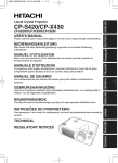
BEDIENUNGSANLEITUNG
Bitte lessen Sie diese Bedienungsanleitung zugunsten der korrekten Bedienung
aufmerksam.
MANUEL D'UTILISATION
Nous vous recommandons de lire attentivement ce manuel pour bien assimiler le
fonctionnement de l'appareil.
MANUALE D'ISTRUZIONI
Vi preghiamo voler leggere attentamente il manuale d'sitruzioni in modo tale da poter
comprendere quanto riportato ai fini di un corretto utilizzo del proiettore.
MANUAL DE USUARIO
Lea cuidadosamente este manual del usuario para poder utilizar corretamente el
producto.
GEBRUIKSAANWIJIZING
Lees voor het qebruik alstublieft deze handleiding aandachtig door, om volledig profijt te
hebben van de uitgebreide mogelijkheden.
BRUKERHÅNDBOK
Vennligst les denne bruksanvisningen grundig for å være garantert driftssikker bruk.
INSTRUÇÕES DO PROPRIETÁRIO
Para assegurar o uso correto do equipamento, por favor leia atentamente este manual do
usuário.
TECHNICAL
REGULATORY NOTICES
ENGLISH
ITALIANO FRANÇAIS DEUTSCH
Please read this user's manual thoroughly to ensure correct usage through understanding.
NEDERLANDS ESPAÑOL
USER'S MANUAL
NORSK
CP-635i
TECHNICAL PORTGÊS
Multimedia LCD Projector
Multimedia LCD Projector
ENGLISH
USER'S MANUAL
Thank you for purchasing this LCD projector.
WARNING • Please read the accompanying manual “SAFETY
INSTRUCTIONS” and this “USER'S MANUAL” thoroughly to ensure correct
usage through understanding. After reading, store this instruction manual in a
safe place for future reference.
NOTE • The information in this manual is subject to change without notice.
• The manufacturer assumes no responsibility for any errors that may appear in this manual
• The reproduction, transmission or use of this document or contents is not permitted without
express written authority.
TRADEMARK ACKNOWLEDGMENT : PS/2, VGA and XGA are registered trademarks of
International Business Machines Corporation. Apple, Mac and ADB are registered trademarks of
Apple Computer, Inc. VESA and SVGA are trademarks of the Video Electronics Standard
Association. Windows is a registered trademark of Microsoft Corporation. Carefully observe the
trademarks and registered trademarks of all companies, even when not mentioned.
CONTENTS
Page
Page
FEATURES .......................................2
BEFORE USE ...................................2
TROUBLESHOOTING ....................20
Contents of Package ..............................2
Part Names.............................................3
Loading the Battery ................................5
Fixing the Handle....................................5
INSTALLATION ................................6
Installation of the Projector and Screen........6
Angle Adjustment ...................................6
Cabling ...................................................7
Power Connection ..................................8
Example of System Setup ......................8
Plug & Play .............................................8
OPERATIONS ...................................9
Power ON ..................................................9
Power OFF ..............................................9
Basic Operation ....................................10
Setup Menu ..........................................12
Input Menu............................................13
Image Menu..........................................14
Options Menu .......................................15
No Signal Menu ....................................16
MAINTENANCE ..............................17
Lamp.....................................................17
Air Filter ................................................19
Other Maintenance ...............................19
OSD Message ......................................20
Indicators Message ..............................21
Symptom ..............................................22
SPECIFICATIONS...........................23
WARRANTY....................................24
.......................................................................................
TABLES
Table 1. Installation Reference.................6
Table 2. Cabling .......................................7
Table 3. Basic Operation ........................10
Table 4. Setup Menu ..............................12
Table 5. Input Menu................................13
Table 6. Image Menu..............................14
Table 7. Options Menu ...........................15
Table 8. No Signal Menu ........................16
Table 9. OSD Message ..........................20
Table 10. Indicators Message ................21
Table 11. Symptom ................................22
Table 12. Specifications .........................23
.......................................................................................
For "TECHNICAL" and "REGULATORY
NOTICE", see the end of this manual.
ENGLISH-1
FEATURES
This liquid crystal projector is used to project various computer signals as well as NTSC / PAL /
SECAM video signals onto a screen. Little space is required for installation and large images can
easily be realized.
Outstanding Brightness
The UHB lamp and high-efficiency optical system assure a high level of brightness.
Partial Magnification Function
Interesting parts of images can be magnified for closer viewing.
Distortion Correction Function
Distortion-free images are quickly available.
Extra-low Noise Function
Acoustic noise level from the unit can be reduced.
BEFORE USE
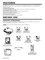
Contents of Package
Make sure all of the following items are included in the package. If anything is missing, please
contact BOXLIGHT at 800-762-5757 or 360-779-7901.
NOTE • Keep the original packing material for future reshipment.
Power Cord
(US Type)
Power Cord
(Europe Type)
USER'S MANUAL
BEDIENUNGSANLEITUNG
Bitte lessen Sie diese Bedienungsanleitung zugunsten der korrekten Bedienung
aufmerksam.
MANUEL D'UTILISATION
Nous vous recommandons de lire attentivement ce manuel pour bien assimiler le
fonctionnement de l'appareil.
MANUALE D'ISTRUZIONI
Vi preghiamo voler leggere attentamente il manuale d'sitruzioni in modo tale da poter
comprendere quanto riportato ai fini di un corretto utilizzo del proiettore.
MANUAL DE USUARIO
Lea cuidadosamente este manual del usuario para poder utilizar corretamente el
producto.
GEBRUIKSAANWIJIZING
Lees voor het qebruik alstublieft deze handleiding aandachtig door, om volledig profijt te
hebben van de uitgebreide mogelijkheden.
BRUKERHÅNDBOK
Vennligst les denne bruksanvisningen grundig for å være garantert driftssikker bruk.
ITALIANO FRANÇAIS DEUTSCH
CP-S370W
Please read this user's manual thoroughly to ensure correct usage through understanding.
NEDERLANDS ESPAÑOL
Liquid Crystal Projector
ENGLISH
Projector
REGULATORY NOTICES
RGB Cable
TECHNICAL PORTGÊS
TECHNICAL
NORSK
INSTRUÇÕES DO PROPRIETÁRIO
Para assegurar o uso correto do equipamento, por favor leia atentamente este manual do
usuário.
User’s Manual
(this manual)
Safety Instructions
Mouse cable
(PS/2)
Component
Video Cable
(with green lead)
VIDEO
STANDBY/ON
RGB
KEYSTONE
MENU
SELECT
MENU
MAGNIFY
Handle
POSITION RESET
FREEZE VOLUME
MUTE
OFF
AUTO
BLANK
Remote Controller
containing Battery
Carrying Bag
ENGLISH-2
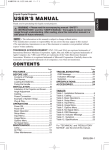
Part Names
Speaker
Zoom Knob
Focus Ring
Handle Hook
Remote Control Sensor
Power Switch
Lens
AC Inlet
(to the Power Cord)
Ventilation Openings
(Intake)
Lens Cap
Foot Adjuster
FRONT/LEFT VIEW OF
THE PROJECTOR
Control Panel (Refer to P.9 "OPERATIONS")
INPUT Button
LAMP Indicator
TEMP Indicator
POWER Indicator
RESET Button
MENU Button
STANDBY/ON Button
KEYSTONE Button
Foot Adjuster Button
Filter Cover
Air Filter and Intake
for the Cooling Fan
(
)
Ventilation Openings
(exhaust)
Rear Foot Adjuster
REAR/RIGHT VIEW OF
THE PROJECTOR
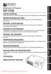
Terminal Panel
(Refer below)
S-VIDEO Terminal
COMPONENT VIDEO
Y Terminal
CB/PB Terminal
CR/PR Terminal
VIDEO IN Terminal
AUDIO IN R Terminal
Remote Control Sensor
RGB IN 1 Terminal
RGB IN 2 Terminal
1
AUDIO IN
AUDIO 1
IN
VIDEO IN
2 AUDIO OUT
RGB IN
2
S-VIDEO IN
USB
RGB OUT
CONTROL
AUDIO IN L Terminal
CONTROL Terminal
AUDIO IN 1 Terminal
RGB OUT Terminal
AUDIO IN 2 Terminal
USB Terminal
AUDIO OUT Terminal
TERMINAL PANEL
ENGLISH-3
ENGLISH
BEFORE USE (continued)
BEFORE USE (continued)
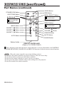
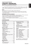
Part Names (continued)
VIDEO Button
STANDBY/ON Button
STANDBY/ON
KEYSTONE Button
KEYSTONE
VIDEO
RGB
MENU SELECT Button
Button
Used to click the left
mouse button.
MENU
SELECT
Used to operate
the mouse shift
function .
POSITION Button
MENU
POSITION RESET
Button
MAGNIFY
Button
MAGNIFY
OFF
Button
RESET Button
Used to click the right
mouse button.
MENU Button
MAGNIFY
RGB Button
MAGNIFY
FREEZE VOLUME
MUTE
OFF
AUTO
VOLUME
Button
VOLUME
Button
FREEZE Button
BLANK
MUTE Button
AUTO Button
BLANK Button
Battery Holder
REMOTE CONTROLLER
(Refer to P.9 "OPERATIONS")
These functions work when the mouse control function is activated. Remember, the POSITION,
VOLUME, KEYSTONE, BLANK ON and MENU ON functions disable the mouse control function.
NOTE • Keep the remote controller away from children and pets.
• Do not give the remote controller any physical impact. Take care not to drop.
• Do not place the heavy objects on the remote controller.
• Do not wet the remote controller or place it on any wet object.
• Do not place the remote controller close to the cooling fan of the projector.
• Do not disassemble the remote controller.
ENGLISH-4
ENGLISH
BEFORE USE (continued)
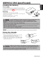
Loading the Battery
First Loading:
In original packing, the battery is installed in the battery holder of
the remote controller with protection film (the transparent film some
of which is inside the battery holder). Pull out the protection film to
load the battery.
“+” side
Replacing:
1. See the reverse side of the remote controller.
2. Pinch the groove and pull out battery holder as the drawing right.
3. Remove the worn battery.
4. Install the new battery with “+” side facing.
5. Push in and click the battery holder.
Pull out
Battery Holder
CAUTION • Incorrect handling of the battery could result in fire or personal injury. The
battery may explode if not handled properly. Be careful in handling the battery
according to instructions of accompaning manual "SAFETY INSTRUCTIONS" and this
manual.
• Use the 3V micro lithium battery type no.CR2025 only.
• When loading the battery, make sure the plus and minus terminals are correctly oriented as
indicated in the remote controller.
• When you dispose the battery, you should obey the law in the relative area or country.
• Keep the battery away from children and pets.
• When not to be used for an extended period, remove the battery from the remote controller.
NOTE Replace the batteries when remote control transmitter operation becomes difficult.
Fixing the Handle
Fix the enclosed handle if you need.
1. Raise up the handle hook, and pass one end of the
handle through the hole of handle hook.
2. Buckle the end of the handle, as the right drawing.
3. Fix the other end of the handle to the other handle
hook in the same way.
2
1
CAUTION • Make sure the handle is fixed before carrying the projector with
the handle. If the projector should be dropped from the handle should be off,
it could result in an injury, and continued use could result in fire or electrical
shock. Do not flourish the projector with the handle.
ENGLISH-5
INSTALLATION
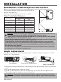
Installation of the Projector and Screen
Refer to the drawing and table below for determining the screen size and projection distance.
The projection distances shown in the table below are for
full size (800 x 600 dots).
a: Distance from the projector to the screen. (±10%)
Table 1. Installation Reference
Screen size
[inches (m)]
a [inches (m)]
Min.
Max.
40 (1.0)
60 (1.5)
62 (1.6)
94 (2.4)
82 (2.1)
123 (3.1)
80 (2.0)
127 (3.2)
164 (4.2)
100 (2.5)
160 (4.1)
205 (5.2)
120 (3.0)
192 (4.9)
246 (6.3)
150 (3.8)
241 (6.1)
308 (7.8)
200 (5.0)
323 (8.2)
411 (10.4)
Top View
a
Side View
CAUTION • Install the projector in a suitable environment according to instructions of
the accompanying manual “SAFETY INSTRUCTIONS” and this manual.
• When you fix this unit with a metal tool and the like, you must connect it with ground
wire; otherwise, fire or electric shock can result.
Connect the ground terminal of AC inlet of this unit with the ground terminal provided at the
building using an optional three-core power-supply cord.
• Please basically use liquid crystal projector at the horizontal position. If you use liquid
crystal projector by the lens up position, the lens down position and the side up position, this
may cause the heat inside to build up and cause damage. Be especially careful not to install it
with ventilation holes blocked.
• Do not install LCD projector in smoke effected environment. Smoke residue may buildup
on critical parts (i.e.LCD panel, Lens Assy etc.).
Angle Adjustment
Use the foot adjusters on the bottom of the projector to adjust the projection angle. It is variable
within 0˚ to 9˚ approximately.
Foot Adjuster
Press the foot adjuster button
Rear Foot Adjuster
1. Lift up the front side of the projector, and pressing the foot adjuster button, adjust the projection
angle.
2. Release the button to lock at the desired angle.
3. Use the rear foot adjuster to adjust the left-right slope. Do not force the foot adjuster screw.
This could damage the adjuster or cause the lock to fail.
CAUTION • Do not release the foot adjuster button unless the projector is being held;
otherwise, the projector could overturn or fingers could get caught and cause personal
injury.
ENGLISH-6
INSTALLATION (continued)
ENGLISH
Cabling
Refer to the table below for connecting each terminal of the projector to a device.
Table 2. Cabling
Function
RGB input
RGB output
Audio input
(from the computer)
Terminal
Cable
RGB IN 1
RGB IN 2
RGB cable with D-sub 15-pin shrink jack
and inch thread screws
RGB OUT
AUDIO IN 1
(interlocked with RGB IN 1)
Audio cable with stereo mini jack
AUDIO IN 2
(interlocked with RGB IN 2)
PS/2 mouse control
PS/2 mouse cable
ADB mouse control
ADB mouse cable
CONTROL
Serial mouse control
Serial mouse cable
RS-232C communication
RS-232C cable
USB mouse control
USB
USB cable
S-video input
S-VIDEO IN
S-video cable with mini DIN 4-pin jack
Video input
VIDEO IN
Video/Audio cable
COMPONENT VIDEO Y
Component video input
COMPONENT VIDEO CB/PB
Component video cable
COMPONENT VIDEO CR/PR
Audio input
(from video equipment)
AUDIO IN L
AUDIO IN R
Video/Audio cable or optional audio cable
with RCA jack
Audio output
AUDIO OUT
Audio cable with stereo mini jack
CAUTION • Incorrect connecting could result in fire or electrical shock.
Please read this manual and the separate “SAFETY INSTRUCTIONS”.
• Before connecting, turn off to all devices to be connected, except for the USB
cable.
• The cables may have to be used with the core set to the projector side. Use the
cables which are included with the projector or specified.
NOTE • Before connecting, read instruction manuals of the devices to be connected, and make sure that the
projector is compatible with the device.
• Secure the screws on the connectors and tighten.
• For some RGB input modes, the optional Mac adapter is necessary.
• Some computers may have multiple display screen modes. Use of some of these modes will not be possible
with this projector.
• Refer to the “TECHNICAL” section for the pin assignment of connectors and RS-232C communication data.
ENGLISH-7
INSTALLATION (continued)
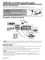
Power Connection
Use the correct power cord depending on the power outlet to be used.
Connect the AC inlet of the projector to the power outlet firmly by the power cord.
CAUTION • Be carful in handling the power
cord according to instructions of the
accompanying manual "SAFETY INSTRUCTIONS"
and this manual.
• Connect the power cord firmly. Avoid using a
loose, unsound outlet failed or contact.
Power
outlet
Power Cord
AC Inlet
Example of System Setup
Display
Monitor
COMPONENT VIDEO
DVD Player
1
AUDIO IN
AUDIO 1
IN
VIDEO IN
2 AUDIO OUT
2
USB
RGB OUT
S-Video Tape
Recorder
RGB IN
S-VIDEO IN
CONTROL
Computer
(notebook type)
Speaker with
amplifier
Computer
(desktop type)
NOTE • When connecting with a notebook computer, set the proper RGB external image output
(setting CRT display or simultaneous display of LCD and CRT). Please read instruction manual of
the notebook for more information.
Plug & Play
This projector is VESA DDC 1/2B compatible. Plug & play is possible by connecting to a computer
that is VESA DDC (Display Data Channel) compatible.
Please use this function by connecting the accessory RGB cable with RGB IN 1 terminal (DDC
1/2B compatible). Plug & play may not operate by other connections.
NOTE • Plug & play is a system configured with peripheral equipment including a computer,
display and an operating system.
• This projector is recognized as a plug & play monitor. Use the standard display drivers.
• Plug & play may not operate by the computer to connect. Use the RGB IN 2 terminal if plug &
play does not operate correctly.
ENGLISH-8
STANDBY/
ON Button
STANDBY/ON Button
VIDEO
STANDBY/ON
RGB
KEYSTONE
POWER Indicator
MENU
SELECT
MENU
Zoom Knob
MAGNIFY
POSITION RESET
FREEZE VOLUME
MUTE
OFF
AUTO
BLANK
Focus Ring
Power Switch
Lens Cap
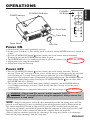
Power ON
1. Check that the power cord is connected correctly.
2. Set the power switch to [ | ]. The standby mode is selected, and the POWER indicator is turned to
orange.
3. Press the STANDBY/ON button
on the control panel or the remote control transmitter.
Warm-up begins and the POWER indicator blinks in green.
4. The POWER indicator ceases blinking and turns to green when power is on. Remove the lens cap.
5. Adjust picture size using the zoom knob.
6. Adjust focus using the focus ring .
Power OFF
1. Press the STANDBY/ON button
on the control panel or the remote controller. Then,the
message "Power off?" will appear on the screen, and the message will disappear by any operation
or no operation for 5 seconds. During this message indication, press the STANDBY/ON
button again. The projector lamp is extinguished and lamp cooling begins. The POWER indicator
blinks orange during lamp cooling. Pressing the STANDBY/ON button
has no effect while
the POWER indicator is blinking.
2. The system assumes the Standby mode when cooling is complete, and the POWER indicator
ceases blinking and changes to orange. Check that the indicator is orange and set the power
switch to [O].
3. The POWER indicator is extinguished when power is off. Do not forget to replace the lens cap.
WARNING • Please read this manual, and the separate “SAFETY
INSTRUCTIONS” thoroughly before using the equipment. Always ensure that
the equipment is used safely.
NOTE • Except in emergencies, follow the above-mentioned procedure for turning power off. If the
projector is used improperly, it may very difficult to turn off the projector caused by heating inside the
unit. And the reduction of life time of lamp and LCD panels will be caused by incorrect procedure.
• To prevent any trouble, turn on/off the projector when the computer or video tape recorder is OFF.
Providing a RS-232C cable is connected, turn on the computer before the projector.
• When a projector continues projecting the same image, the image may remain as an afterimage.
Please do not project the image same for a long time.
ENGLISH-9
ENGLISH
OPERATIONS
OPERATIONS (continued)
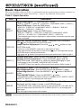
Basic Operation
The basic operations shown in Table 3 is performed from the supplied remote control transmitter or
the projector control panel. Items indicated by (*) may be used from the control panel.
Table 3 . Basic Operation
Item
Description
Select Input Signal (*) : Press the INPUT button.
RGB IN 1→RGB IN 2→ VIDEO IN → S-VIDEO IN → COMPONENT VIDEO (→ RGB IN 1)
Select RGB Input : Press the RGB button.
INPUT
SELECT
VIDEO IN / S-VIDEO IN / COMPONENT VIDEO → RGB IN 1 / RGB IN 2
RGB IN 1 → RGB IN 2 (→ RGB IN 1)
Select Video Input : Press the VIDEO button.
RGB IN 1 / RGB IN 2 → VIDEO IN / S-VIDEO IN / COMPONENT VIDEO
VIDEO IN → S-VIDEO IN → COMPONENT VIDEO (→ VIDEO IN)
• The selected signal name is displayed for approximately 3 seconds when the input
signal is changed.
Set/Clear Position Adjustment Mode : Press the POSITION button.
The [
] icon is displayed in the POSITION mode.
POSITION
Image Position Adjustment: Press the
POSITION mode.
,
,
and
buttons in the
RESET (*)
Initialize Each Item : Select an item and press the RESET button.
Initialize Position Adjustment : Press the RESET button and the
POSITION mode. This function is valid only when RGB signal is input.
• Valid only in the MAGNIFY mode with a video signal is input.
• After approximately 10 seconds of inactivity the [ ] icon is extinguished and the
POSITION mode is cleared automatically.
• , , and
buttons may operate as the mouse control button. Refer to page 4.
• Valid except for the VOLUME, LANGUAGE and H PHASE.
• The RESET button may operate as the mouse control button. Refer to page 4.
MAGNIFY
Set MAGNIFY Mode : Press the MAGNIFY
button.
Move Magnified Area : Run the POSITION in the MAGNIFY mode.
Adjust Magnification : Press the MAGNIFY
/
button in MAGNIFY
mode.
Clear MAGNIFY Mode : Press the MAGNIFY
button.
OFF
• The MAGNIFY mode is cleared by running or setting the AUTO, ASPECT, INPUT
SELECT or VIDEO, or by changing the input signal.
Set/Clear FREEZE Mode : Press the FREEZE button. The [II] icon is
displayed, and the image is frozen, in the FREEZE mode.
FREEZE
• The FREEZE mode is cleared by running or setting POSITION, VOLUME, MUTE,
Automatic Adjustment, BLANK ON/OFF, or MENU ON/OFF, or by changing the
input signal.
• Do not forget to clear frozen static images.
NOTE • Strong light and obstacles will interfere with operation of the remote control transmitter.
ENGLISH-10
OPERATIONS (continued)
ENGLISH
Items indicated by (*) may be used from the control panel.
Table 3. Basic Operation (continued)
Item
Description
VOLUME
Volume Adjustment : Press the VOLUME
MUTE
Set/Clear Mute Mode : Press the MUTE button. No sound is heard in the
MUTE mode.
AUTO
/
button.
Automatic Adjustment at RGB Input : Press the AUTO button. Horizontal
position(H.POSIT), vertical position (V.POSIT),clock phase (H.PHASE), and
horizontal size(H.SIZE) are automatically adjusted. Use with the window at
maximum size in the application display.
Automatic Adjustment at Video Input : Press the AUTO button. A signal
type appropriate for the input signal is selected automatically. Valid only
when AUTO is set for VIDEO on the menu.
• This operation requires approximately 10 seconds. It may not function correctly with
some input signals.
BLANK
ON/OFF
Set/Clear Blank Mode: Press the BLANK button. No image is displayed in
the Blank mode. The screen color is as set in BLANK on the Image menu.
Menu Display Start/Stop: Press the MENU button.
MENU
• The menu display is terminated automatically after approximately 10 seconds of
ON/OFF (*)
inactivity.
Select Menu Type: Press the MENU SELECT button. Allows the user to
select the normal menu or the single menu. Only the selected item is
displayed on the single menu, and other items are displayed with the
and
buttons as with the normal menu.
MENU
SELECT
• Valid only when the Setup menu is used. Push the MENU SELECT button after
selecting items such as "BRIGHTNESS".
• The MENU SELECT button may operate as the mouse control button. Refer to
page 4.
Normal menu
Single menu
(MENU SELECT)
SETUP
INPUT
BRIGHT
CONTRAST
V POSIT
H POSIT
H PHASE
H SIZE
COLOR BAL R
COLOR BAL B
ASPECT
IMAGE
OPT.
0
-2
100
100
+1
800
0
0
CONTRAST
-2
Set / Clear KEYSTONE Mode : Press the KEYSTONE
button.
/
button.
KEYSTONE Adjust KEYSTONE : Press the
(*) • The image may not be appeared properly when this function is activated on same
input signals.
• The adjustable range of distortion correction will be different among input signals.
ENGLISH-11
OPERATIONS (continued)
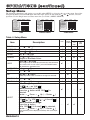
Setup Menu
The following adjustments and settings are possible when SETUP is selected at the top of the menu. Part of the
Setup menu differs between RGB input and video input. Select an item with the
and
buttons, and start
operation. Use the Single menu to reduce menu size (see Table 3, MENU SELECT).
SETUP
INPUT
IMAGE
OPT.
SETUP
0
-2
BRIGHT
CONTRAST
V POSIT
H POSIT
H PHASE
H SIZE
COLOR BAL R
COLOR BAL B
ASPECT
INPUT
IMAGE
OPT.
BRIGHT
CONTRAST
SHARPNESS
COLOR
TINT
COLOR BAL R
COLOR BAL B
ASPECT
100
100
+1
800
0
0
0
+1
+1
0
0
0
0
SETUP
IMAGE
OPT.
0
+1
+1
0
0
0
COMPONENT
VIDEO/S-VIDEO
RGB
INPUT
BRIGHT
CONTRAST
COLOR
H PHASE
COLOR BAL R
COLOR BAL B
ASPECT
Table 4. Setup Menu
COMPONENT
Item
BRIGHT
CONTRAST
V POSIT
H POSIT
H PHASE
Description
Dark
↔
Light
Weak
↔
Strong
Down
↔
Up
Left
↔
Right
Left
↔
Right
• Adjust to eliminate flicker.
Small
↔
Large
VIDEO
S-VIDEO
480i
575i
480P
720P
1080i
✔
✔
✔
✔
✔
✔
✔
✔
✔
✔
-
-
-
✔
-
✔
✔
✔
-
-
-
RGB
H SIZE
• The image may not be displayed correctly if the horizontal
size is excessive. In such cases, press the RESET button,
and initialize the horizontal size.
SHARPNESS
COLOR
Soft
Light
↔
↔
Clear
Dark
-
✔
✔
-
-
✔
✔
TINT
Red
↔
Green
-
✔
-
-
✔
✔
✔
✔
✔
✔
✔
✔
✔
-
-
✔
-
✔
✔
-
• Valid only when NTSC or NTSC 4.43 signal is received.
COLOR BAL R Light
COLOR BAL B Light
ASPECT
↔
↔
Dark
Dark
Select Image Aspect Ratio :
4:3[
]
↔
16:9[
]
Select Position of Image:
] is
Press the
button while 16:9[
selected.
Center →
Down →
Up ( → Center
)
Select Image Aspect Ratio:
4:3[
] ↔ 16:9[
] ↔ 4:3small[
]
Select Position of Image :
Press the
button
while 16:9[
] / 4:3 small[
] is selected.
Center →
Down →
Up ( → Center
)
• 4:3 small may not be displayed correctly with some input
signals.
ENGLISH-12
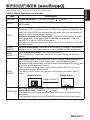
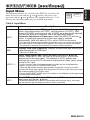
Input Menu
The following functions are available when INPUT is selected on the
menu. Select an item with the
and
buttons, and start or stop
operation with the
and
buttons. The function indicated (**) are
effective on video input mode only, not on RGB input mode.
Table 5. Input Menu
Item
AUTO
SETUP
AUTO
RGB
VIDEO
HDTV
INPUT
IMAGE
OPT.
EXECUTE
CANCEL
Description
Automatic Adjustment at RGB Input: Select the EXECUTE with the
button. Horizontal position (H.POSIT), vertical position (V.POSIT), clock
phase (H.PHASE), and horizontal size (H.SIZE) are automatically adjusted.
Use with the window at maximum size in the application display.
Automatic Adjustment at Video Input: Select the EXECUTE with the
button. A signal type appropriate for the input signal is selected
automatically. Valid only when AUTO is set for VIDEO on the menu.
• This operation requires approximately 10 seconds. It may not function correctly with
some input signals. Pressing the AUTO button in this case may correct this problem.
• This function is the same as for the AUTO function in Basic operation.
RGB
Displays RGB Input Frequency: Displays the horizontal and vertical sync
signal frequencies for RGB input.
• Valid only at RGB input.
Select Video Signal Type: Select the signal type with the
and
buttons. Select NTSC, PAL, SECAM, NTSC4.43, M-PAL, or N-PAL as
appropriate for the input signal. The selection of AUTO enables and
executes the function AUTO (Automatic Adjustment at Video Input), except
for the N-PAL input.
VIDEO (**)
HDTV
• Use this function when the image becomes unstable (eg. the image becomes
irregular, or lacks color) at VIDEO/S-VIDEO input.
• Automatic Adjustment requires approximately 10 seconds. It may not function
correctly with some input signals. Pressing the AUTO button in this case may correct
this problem except for the N-PAL input.
• For the COMPONENT VIDEO input, this function is not effective and the signal type
is distinguished automatically.
Select HDTV mode: Select the 1035i mode or 1080i mode suitable for the
input signal with the
/
button.
• When the selected HDTV mode is incompatible with the input signal, the image
may be incorrect (eg. the display position or color is incorrect).
ENGLISH-13
ENGLISH
OPERATIONS (continued)
OPERATIONS (continued)
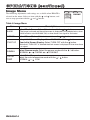
Image Menu
SETUP
The following adjustments and settings are available when IMAGE is
selected on the menu. Select an item with the
and
buttons, and
start or stop operation with the
and
buttons.
INPUT
IMAGE
OPT.
BLANK
MIRROR
START UP
GAMMA
COLOR TEMP
Table 6. Image Menu
Item
Description
Select Blank Screen Color: Select color with the
/
button.
BLANK
• The image is cleared and the entire screen is displayed in the selected color, when
BLANK mode is set with BLANK ON, or when there is no signal for 5 minutes.
MIRROR
Select Mirror Status: Select mirror status with
START UP
Setup Initial Screen Display: Select TURN ON with the
Clear Initial Screen Display: Select TURN OFF with the
/
button.
• Note that if TURN OFF is selected the blank screen is displayed in blue when there
is no signal.
GAMMA
Select Gamma mode: Select the gamma mode with the
NORMAL ↔ CINEMA ↔ DYNAMIC
COLOR
TEMP
Select Color Temperature:
Select the color temperature mode with the
↔
LOW
NORMAL
ENGLISH-14
button.
button.
/
button.
/
button.
Options Menu
SETUP
The following adjustments and settings are available when OPT. is
selected on the menu. Select an item with the
and
buttons, and
start or stop operation with the
and
buttons.
Table 7. Options Menu
Item
INPUT
IMAGE
OPT.
16
VOLUME
MENU COLOR
LANGUAGE
AUTO OFF
SYNC ON G
WHISPER
Description
↔
VOLUME
Reduce
Increase
MENU COLOR
Select Menu Background Color: Select with the
/
button.
LANGUAGE
Select Menu Display Language: Select with the
/
button.
AUTO OFF
Set AUTO OFF: Set 1~99 minutes with the
/
button. The system
automatically enters the standby mode when a signal is not received for
the set time.
Clear AUTO OFF: Select STOP (0 min.) with the
button. When
STOP is selected the system does not enter the standby mode even if
no signal is received.
SYNC ON G Valid: Select TURN ON with the
button.
SYNC ON G Invalid: Select TURN OFF with the
button.
SYNC ON G
WHISPER
• May not be displayed correctly with some input signals when SYNC ON G is
valid. In such cases, remove the signal connector so that no signal is received,
set SYNC ON G to invalid, and reconnect the signal.
Set / Clear WHISPER Mode: Press the
/
button. When the
WHISPER is selected, the WHISPER mode is active. In the WHISPER
mode, acoustic noise level from the unit is reduced, and brightness level
on screen is a little lower.
ENGLISH-15
ENGLISH
OPERATIONS (continued)
OPERATIONS (continued)
No Signal Menu
The same adjustments and settings are available with the Image and
Options menus when the MENU button is pressed during display of the
“NO INPUT IS DETECTED ON ***” or “SYNC IS OUT OF RANGE
ON ***” message while no signal is received.Select an item with the
and
buttons, and start or stop operation with the
and
buttons.
VOLUME
BLANK
MIRROR
START UP
MENU COLOR
LANGUAGE
AUTO OFF
SYNC ON G
WHISPER
16
Table 8. No Signal Menu
Item
Description
↔
Increase
• When this function is used, audio input is automatically switched to video. The
audio input can be switched by moving the DISK PAD left and right during the
display of the volume adjustment bar. The volume adjustment bar is displayed by
pressing VOLUME
/
button.
Reduce
VOLUME
Select Blank Screen Color: Select the color with the
/
button.
BLANK
• When the blank mode is set with BLANK ON, by absence of a signal, or by
input of a non-standard signal, the image is cleared and the complete screen is
displayed in the selected color.
MIRROR
Select Mirror Status: Select the mirror status with the
START UP
MENU COLOR
LANGUAGE
AUTO OFF
SYNC ON G
WHISPER
ENGLISH-16
/
Setup Initial Screen Display: Select the TURN ON with the
Clear Initial Screen Display: Select the TURN OFF with the
button.
button.
button.
• Note that if TURN OFF is selected the blank screen is displayed in blue when
there is no signal.
Select Menu Background Color: Select the color with the
/
button.
Select Menu Display Language: Select the language with the
/
button.
Set AUTO OFF: Set 1~99 minutes with the
/
button. The system
automatically enters the standby mode when a signal is not received for
the set time.
Clear AUTO OFF: Select the STOP (0 min.) with the
button. When
the STOP is selected the system does not enter the standby mode even
if no signal is received.
SYNC ON G Valid: Select the TURN ON with the
button.
SYNC ON G Invalid: Select the TURN OFF with the
button.
• May not be displayed correctly with some input signals when the SYNC ON G is
valid. In such cases, remove the signal connector so that no signal is received,
set the SYNC ON G to invalid, and reconnect the signal.
Set / Crear WHISPER Mode: Press the
/
button. When the
WHISPER is selected, the WHISPER mode is active. In the WHISPER
mode, acoustic moise level from the unit is reduced, and brightness
level on screen is a little lower.
Lamp
HIGH VOLTAGE
HIGH TEMPERATURE
HIGH PRESSURE
Contact BOXLIGHT before replacing the lamp.
For the optional lamp, see the item “Optional Parts” of the Table 12.
Before replacing the lamp, switch power OFF, remove the power cord from the power outlet, and
wait approximately 45 minutes until the lamp has cooled. The lamp may explode if handled at high
temperatures.
WARNING A mercury lamp used in this LCD projector is made of glass and has high
internal pressure. The mercury lamp can burst with a big noise due to deterioration
resulting from a shock, crack and passage of time, and can end its service life in unlit
condition. Lamps also have a considerably different service life and can sometimes end up
in burst or turn to unlit condition soon after use. Furthermore, when the lamp is blown up,
glass fragments can get scattered around the lamp house and some gas containing mercury
inside the lamp can leak out of the projector’s air vent.
• Handle the lamp with utmost care as it can burst during use if subjected to a shock or
impact or if scratched or cracked.
• Probability for the burst will increase if the lamp is used for extended period of time or
used exceeding the period of replacement. You are advised to follow instructions for lamp
replacement as soon as they are given (Refer to Table 9 of Page 20, Table 10 of Page 21).
Avoid any reuse of an old lamp (used lamp) since such reuse can result in burst.
• In case the lamp gets blown up in a short period of time after use, some electrical failures
or troubles other than the lamp itself may be suspected as causes. Under such
circumstances, consult BOXLIGHT.
• Should the lamp burst (accompanied by a big bursting noise), perform ventilation
sufficiently, and exercise maximum caution not to inhale any gas out of the projector’s air
vent or not to let it enter your eyes or mouth.
• Should the lamp burst (accompanied by a big bursting noise), make absolutely sure to
unplug the power cord from the outlet.
You should not engage in cleanup or replacement of the lamp by yourself since scattered
glass fragments can damage the inside of projector or can result in personal injury when
you handle it.
• When you dispose of any used lamps, be sure to observe and follow local ordinances and
regulations of the area or district where they are subjected to disposal. Generally speaking,
the lamps are treated similarly as glasses and bottles in most cases, but there are areas or
districts where lamps are classified as a separate collection, and so be sure to use caution.
• Never use the lamp in a state where the lamp cover is removed.
Lamp Life
Projector lamps have a finite life. The image will become darker, and hues will become weaker,
after a lamp has been used for a long period of time.
Replace the lamp if the LAMP indicator is red, or the CHANGE THE LAMP message appears
when the projector is switched ON. See Table 9 of P.20 and Table 10 of P.21.
NOTE • The LAMP indicator is also red when the lamp unit reaches high temperature. Before
replacing the lamp, switch power OFF, wait approximately 20 minutes, and switch power ON again.
If the LAMP indicator is still red, replace the lamp.
ENGLISH-17
ENGLISH
MAINTENANCE
MAINTENANCE (continued)
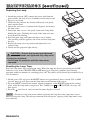
Replacing the Lamp
1. Switch the projector OFF, remove the power cord from the
power outlet, and wait at least 45 minutes for the unit to cool.
2. Prepare a new lamp.
3. Check that the projector has cooled sufficiently, and gently
turn it upside down.
4. Loosen the two screws as shown in the diagram, and remove
the lamp cover.
5. Loosen the three screws, and gently remove the lamp while
holding the grips. Touching the inside of the lamp case may
result in uneven coloring.
6. Install the new lamp and tighten the three screws firmly.
Also steadily push the opposite side of the screwed lamp into
the unit.
7. Replace the lamp cover in position and tighten the two
screws firmly.
8. Gently turn the projector right-side up.
CAUTION • Ensure that screws are tightened
properly. Screws not tightened fully may result
in injury or accidents.
• Do not use the projector with the lamp cover
removed.
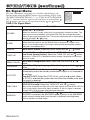
Resetting the Lamp Timer
Reset the lamp timer after replacing the lamp. When the lamp has been replaced after the LAMP
indicator is red, or the CHANGE THE LAMP message is displayed, complete the following
operation within ten minutes of switching power ON. The power will be turned off automatically in
over 10 minutes.
1. Switch power ON, and press the RESET button, for approximately three seconds. The ‘LAMP
xxxx hr’ message will appear on the lamp timer on the bottom of the screen.
2. Press the MENU button on the remote control transmitter, or the RESET button on the control
panel, while the lamp timer is displayed. The ‘LAMP xxxx → 0 ■ CANCEL’ message will
then appear.
3. Press the
and select 0, and wait until the timer display is cleared.
NOTE • Do not reset the lamp timer without replacing the lamp. Reset the lamp timer always
when replacing the lamp. The message functions will not operate properly if the lamp timer is not
reset correctly.
ENGLISH-18
Air Filter
Cleaning the air Filter
The air filter should be cleaned as described below at intervals of approximately 100 hours.
1. Switch the projector power supply OFF, and remove the power cord from the power outlet.
2. Clean the air filter with a vacuum cleaner.
Replacing the Air Filter
Replace the air filter if contamination cannot be removed, or if it is damaged.
1. Remove the filter cover.
2. Remove the old filter.
3. Set the new filter and the filter cover.
CAUTION • Switch power OFF and remove the power cord from the power
outlet before beginning maintenance work. Please read the separate “SAFETY
INSTRUCTIONS” thoroughly to ensure that maintenance is performed correctly.
• Replace the air filter if contamination cannot be removed, or if it is damaged.
Contact BOXLIGHT for service. For the optional air filter, see the item “Optional
Parts” of the Table 12.
• Do not use the equipment with the air filter removed.
• When the air filter is clogged with dust etc. the power supply is switched OFF
automatically to prevent the temperature rising inside the projector.
Other Maintenance
Maintenance Inside the Equipment
For safety reasons, ensure that the equipment is cleaned and checked by BOXLIGHT once every
two years. Maintaining the equipment by yourself is dangerous.
Cleaning the Lens
Gently wipe the lens with lens cleaning paper. Do not touch the lens with your hands.
Cleaning the Cabinet and Remote control transmitter
Gently wipe with a soft cloth. If dirt and stains etc. are not easily removed, use a soft cloth
dampened with water, or water and a neutral detergent, and wipe dry with a soft, dry cloth.
CAUTION • Switch power OFF and remove the power cord from the power
outlet before beginning maintenance work. Please read the separate “SAFETY
INSTRUCTIONS” thoroughly to ensure that maintenance is performed correctly.
• Do not use detergents or chemicals other than those noted above (e.g. benzene
or thinners).
• Do not use cleaning sprays.
• Do not rub with hard materials, or tap the equipment.
ENGLISH-19
ENGLISH
MAINTENANCE (continued)
TROUBLESHOOTING
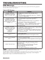
OSD Message
The messages as described below may appear on the screen at power ON. Take the appropriate
measures when such messages appears.
Table 9. OSD Message
Message
Contents
The usage time of lamp will be reaching 2000 hr
CHANGE THE LAMP
AFTER REPLACING LAMP,
shortly.
RESET THE LAMP TIME.
It is recommended to replace the lamp soon. Prepare a
(*1) new lamp as a replacement.
CHANGE THE LAMP
AFTER REPLACING LAMP,
RESET THE LAMP TIME.
THE POWER WILL TURN OFF
AFTER ** hr.
(*1)
CHANGE THE LAMP
AFTER REPLACING LAMP,
RESET THE LAMP TIME.
THE POWER WILL
TURN OFF
AFTER 0 hr.
NO INPUT IS DETECTED
ON ***
SYNC IS OUT OF RANGE
ON ***
CHECK THE AIR FLOW
The usage time of lamp will be reaching 2000 hr shortly.
It is recommended to replace the lamp within * *
hours.
It might be happened that the lamp is cut off before * * hr
by any chance. Power will be switched OFF
automatically in * * hours. Replace the lamp as shown in
P.17~18 “Lamp”. Always reset the lamp timer after
replacing the lamp.
The usage time of lamp is about to reach. Power will be
switched OFF in a few minutes.
Switch power OFF immediately and replace the lamp as
shown in P.17 ~18 “Lamp”. Always reset the lamp timer
after replacing the lamp.
No input signal found.
Check signal input connections and signal sources.
The horizontal or vertical frequency of the input signal is
not within the specified range.
Check the specifications of the equipment and the signal
source.
The internal temperature has risen.
Switch power OFF, and wait 20 minutes until the
equipment cools.
Check the following and Switch power ON again.
* Are the ventilation openings blocked.
* Is the air filter dirty.
* Is the ambient temperature in excess of 35°C.
NOTE (*1) This message is cleared automatically after approximately three minutes, and
appears every time power is switched ON.
(*2) The unit has a function to turn the power off which will be active when the usage time reaches
2000 hr. However the life of lamp might be much different among lamps, so that it might be
happened that a lamp is cut off before the function is active.
ENGLISH-20
Indicators Message
The POWER indicator, LAMP indicator, and TEMP indicator are lit and blank as follows. Take the
appropriate measures.
Table 10. Indicators Message
POWER LAMP TEMP
indicator indicator indicator
Contents
Lights
orange
Turns off Turns off The Standby mode has been set.
Blinks
green
Turns off Turns off Warming up. Please wait.
Lights
green
Turns off Turns off ON. Normal operation possible.
Blinks
orange
Turns off Turns off Cooling. Please wait.
Blinks red
-
Blinks
/Lights red
Lights
red
Blinks
/Lights red
Blinks
red
Cooling. Please wait.
The error is found. Take the appropriate measures when the
POWER indicator ceases blinking
Lamp is not lit.
The interior of the equipment may be too hot. Switch power OFF,
wait 20 minutes until the equipment cools, and check whether the
Turns off
ventilation openings are blocked, whether the air filter is dirty, or
whether the ambient temperature exceeds 35 °C. And switch
power ON again. Replace the lamp if the same problem occurs.
-
Lamp or lamp cover is not found, or hasn’t been fitted in correctly.
Switch power OFF, and wait for 45 minutes until the equipment
Turns off
cools. Check fitting of the lamp and lamp cover, and switch power
ON again. Contact BOXLIGHT if the same problem occurs again.
The cooling fan is not operating.
Switch power OFF, and wait for 20 minutes until the equipment
cools. Check for foreign matters in the fan, and switch power ON
again. Contact BOXLIGHT if the same problem occurs again.
The interior of the equipment is too hot.
Switch power OFF, and wait for 20 minutes until the equipment
Blinks
cools. Check whether the ventilation openings are blocked,
Turns off Lights red
whether the air filter is dirty, or whether the ambient temperature
/Lights red
exceeds 35 °C. Then switch power ON again. Contact BOXLIGHT
if the same problem occurs again.
The interior of the equipment is too cool.
Lights
Blinks
Blinks Check whether the ambient temperature is below 0°C. Contact
BOXLIGHT if the same problem occurs when the ambient
green
red
red
temperature is 0~35°C.
Blinks
Turns off
/Lights red
Blinks
red
NOTE When the internal temperature becomes excessive power is switched OFF automatically
for safety reasons, and the indicator is extinguished. Set the power switch to [O] and wait for 20
minutes until the equipment has cooled sufficiently.
ENGLISH-21
ENGLISH
TROUBLESHOOTING (continued)
TROUBLESHOOTING (continued)
Symptom
Before requesting repair, consult the following chart. If the situation cannot be corrected, then
contact BOXLIGHT at 800-762-5757 or 360-779-7901.
Table 11. Symptom
Symptom
The power is not
turned on.
Possible cause
Remedy
The main power switch is not
turned on.
Turn on the main power switch.
The power cord is
disconnected.
Plug the power cord into an AC
power outlet.
The main power was
disconnected during operation
by the power failure and so on.
Turn off the projector with the main
power switch (set the power switch
to [O]), and wait for about 20
minutes. When the equipment has
cooled enough, turn power on.
9
The input is not correctly set.
Use the projector or remote control
transmitter to set.
10
No signal input.
Connect correctly.
7,8
The projector is not correctly
connected.
Connect correctly.
7,8
No video or audio.
Video is present but
The volume is set to minimum.
no audio.
Press VOLUME
on the remote
control or display the menu screen
and adjust the volume.
Mute is turned on.
Press the MUTE
The projector is not correctly
connected.
Connect correctly.
button.
Audio is present but The brightness adjustment knob Select BRIGHT with the MENU
button and the press the
button.
is rotated fully clockwise.
no video.
The lens cap is still attached.
Colors are pale and Color density and color
color matching is
matching are not correctly
poor.
adjusted.
Images are dark.
Video is blurred.
ENGLISH-22
Page
Remove the lens cap.
8,9
11,15
11
7,8
12
9
Adjust the video.
12
Brightness and contrast are not
Adjust the video.
correctly adjusted.
12
The lamp is nearing the end of
its service life.
Replace with a new lamp.
17
WHISPER mode is set.
Clear WHISPER mode.
15
Focus or H PHASE is out of
adjustment.
Adjust the focus or H PHASE.
9,12
ENGLISH
SPECIFICATIONS
Table 12. Specifications
Item
Specification
Product name
Liquid
crystal
panel
Liquid crystal projector
Panel size
2.3 cm (0.9 type)
Drive system
TFT active matrix
Pixels
480,000 pixels (800 horizontal x 600 vertical)
Lens
Zoom lens F=1.7 ~ 2.1 f=36.8 ~ 47.8 mm
Lamp
200 W UHB
Speaker
1.0W+1.0W (stereo)
Power supply
AC100 ~ 120V, 3.3A / AC220 ~ 240V, 1.4A
Power consumption
310W
Temperature range
0 ~ 35°C (Operating)
Size
298 (W) x 94.6 (H) x 228 (D) mm
Weight (mass)
3.25 kg
1
RGB
signal
input
RGB IN
2
AUDIO IN
Video
signal
input
1
2
Video: Analog 0.7Vp-p, 75Ω terminator (positive)
H/V. sync.: TTL level (positive/negative)
Composite sync.: TTL level
D-sub 15-pin shrink jack
200mVrms, 50 kΩ (max. 3.0Vp-p)
Stereo mini jack
VIDEO IN
1.0Vp-p, 75Ω terminator
RCA jack
S-VIDEO IN
Brightness signal: 1.0Vp-p, 75Ω terminator
Color signal: 0.286Vp-p (NTSC, burst signal),75Ω terminator
0.300Vp-p (PAL/SECAM, burst signal),75Ω terminator
Mini DIN 4-pin jack
Y
1.0 Vp-p, 75 Ω Terminator (Positive)
COMPONENT
CB/PB 0.7 Vp-p, 75 Ω Terminator (Positive)
VIDEO
CR/PR 0.7 Vp-p, 75 Ω Terminator (Positive)
AUDIO IN
Signal
output
Control
functions
L
R
200mVrms, 50 kΩ (max. 3.0Vp-p)
RCA jack
RGB OUT
Video: Analog 0.7Vp-p, 75Ω output impedance (positive)
H/V. sync.: TTL level (positive/negative)
Composite sync.: TTL level
D-sub 15-pin shrink jack
AUDIO OUT
200mVrms, output impedance 1 kΩ (max. 3.0Vp-p)
Stereo mini jack
CONTROL
D-sub 15-pin shrink plug
USB
USB jack (B type)
Optional Parts
Lamp: CP635I-930 (DT00431)
Air Filter: MU01421
* For others, consult your dealer.
NOTE • This specifications are subject to change without notice.
ENGLISH-23
WARRANTY
LIMITED WARRANTY
BOXLIGHT CORPORATION("BOXLIGHT") warrants that each Boxlight CP-635i ("the Product") sold
hereunder will conform to and function in accordance with the written specifications of BOXLIGHT. Said
limited warranty shall apply only to the first person or entity that purchases the Product for personal or business
use and not for the purpose of distribution resale. Said warranty shall continue for a period of two (2) years from
the date of such purchase. BOXLIGHT does not warrant that the Product will meet the specific requirements of
the first person or entity that purchases the Product for personal or business use. Lamp is warrantied for 120
days.
BOXLIGHT CORPORATION's liability for the breach of the foregoing limited warranty is limited to the repair
or replacement of the Product or refund of the purchase price of the Product, at BOXLIGHT's sole option. To
exercise the Purchaser's rights under the foregoing warranty, the Product must be returned at the Purchaser's sole
cost and expense, to BOXLIGHT or any authorized service center provided, however, that the Product must be
accompanied by a written letter explaining the problem and which includes (i) proof of purchase; (ii) the dealer's
name; (iii) the model and serial number of the Product. A return authorization number, issued by the
BOXLIGHT customer service department, must also be clearly displayed on the outside of the shipping carton
containing the Product.
WARRANTY LIMITATION AND EXCLUSION
BOXLIGHT CORPORATION shall have no further obligation under the foregoing limited warranty if the
Product has been damaged due to abuse, misuse, neglect, accident, unusual physical or electrical stress,
unauthorized modification, tampering, alterations, or service other than by BOXLIGHT or its authorized agents,
causes other than from ordinary use or failure to properly use the Product in the application for which said
Product is intended.
DISCLAIMER OR UNSTATED WARRANTIES
The warranty printed above is the only warranty applicable to this purchase.
All other warranties express or implied, Including, but not limited to, the implied warranties or merchantability
and fitness for a particular purpose are disclaimed. There are no warranties that extend beyond the face of hereof
and the forgoing warranty shall not be extended, altered or varied except by written instrument signed by
BOXLIGHT CORPORATION.
LIMITATION OF LIABILITY
It is understood and agreed that BOXLIGHT's liability whether in contract, in tort, under any warranty, in
negligence or otherwise, shall not exceed the return of the amount of the purchase price paid by purchaser and
under no circumstances shall BOXLIGHT be liable for special, indirect or consequential damages. The price
stated for the Product is a consideration in limiting BOXLIGHT's liability. No action regardless of form, arising
out of the agreement to purchase the product, may be brought by purchaser more than one year after the cause of
action has accrued.
Boxlight
19332 Powder Hill Place
Poulsbo, WA 98370-7407-USA
www.boxlight.com
U.S. and Canada 800-762-5757
International 360-779-7901
ENGLISH-24
*QR53221*
Printed in Japan