1
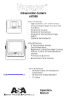
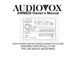
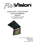
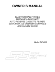
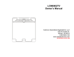
R
LCM1511WTV
COLOR LCD MONITOR
WITH TV TUNER
OWNER’S MANUAL
Audiovox Specialized Applications, LLC
23319 Cooper Drive
Elkhart, IN 46514
800-688-3135
www.asaelectronics.com
PACKING
Monitor
Remote Control
Interface Cable
12V Power Cord
Batteries: Size AAA x 2
Mounting Hardware
Manual
WARNING
TABLE OF CONTENTS
Page
1
1. LCM Monitor
2
LCD, Tuner Pack, IR Remote Controller
3
2. Feature Function, IR Remote
3
2-1 Power
3
2-2 Input Signal Detection
3
2-3 Contrast/Color/Brightness Adjustment
3
2-4 Volume Adjustment
3
2-5 Audio Mute
4
3. Manual Functions
4
3-1 Key Functions
4
3-2 Volume Control
4
3-3 OSD Icons and Functions Description
4
3-4 Video Adjustments
4
Reference table of OSD Functions and Descriptions
5
4. Feature Functions
6
4-1 No Signal Detection
6
4-2 Auto Memory Function
6
4-3 PC VGA Multi-Sync mode
6
5. Tuner Functions: (ACC Function charged only by IR Remote
7
5-1 Power
7
5-2 TV/CATV/AV1/AV2/ Mode Selection
7
5-3 TV/CATV Channel Programming
7
5-4 Input Signal Detection
8
5-5 Channel Selection
8
5-6 Channel Recall
8
5-7 Contrast/Color/Brightness Adjustment
8
5-8 Volume Adjustment
8
5-9 Audio Mute
8
6. Installation of Monitor and Tuner Pack
9
7. Installation Procedure
10
8. Specifications
11
9. Help Page
12
10. Optional Product List
13
11. Notes
14
1. LCM Monitor
Front
H
G
G
A B CDE F
Rear
A. IR Eye
B. Menu
C. Select
D. ADJ-
E. ADJ+
F. Power LED
G. Speakers
H. LCD Panel
A B
A. VGA Input
B. DC 12V IN
C D
C. A/V
D. Interface Cable to Tuner AUX
Page 1
LCD, Tuner Pack, IR Remote Control
Remote Controller
POWER ON/OFF
CHANNEL SELECT
VOLUME ADJUST +/COLOR COLOR
TV/AV
MENU
MUTE
SPKR ON/OFF
CONTRAST CONTRAST
BRIGHT
BRIGHTEN
Page 2
2. Feature Function, IR Remote
2-1 Power
Pointing the remote towards the IR eye on the LCD, press and
hold
the POWER On/Off button on the remote controller unit until it
turns on
the system. Repeat this procedure to turn off system.
Power On- The LCD monitor will light up, and the green power
light on
the front panel will be ON.
The OSD (On Screen Display) will show the mode of operation.
Power Off- The monitor screen will be dark, the green power
light will
change to orange. The system will go to stand-by mode.
2-2 Input Signal Detection
Tuner system will detect if a signal is received or if a signal is not
received in every mode of signal input. If there is no signal,
screen
will display “No Signal”. Otherwise, the signal will be displayed
showing the mode.
2-3 Contrast/Color/Brightness Adjustment
If you want to adjust contrast/Color/Brightness, press the
appropriate
button. The screen will display the one you choose, then use t
or s
Volume to adjust it within 2.5 seconds. If you take over 2.5
seconds
to adjust, the screen display will disappear and the system will
reset
to t or s Volume.
2-4 Volume Adjustment
Use the t or s volume button to increase or decrease the
audio
volume. You will see the “Volume Bar” on the screen.
2-5 Audio Mute
Press the Mute button to disable audio output. The screen will
display
“Mute” on upper right corner of the monitor.
To cancel mute status, just press Mute key again. The “Mute”
message on upper right corner will disappear.
Page 3
3. Feature Functions by Manual
3-1 Key Functions
There are 4 buttons on the monitor which are “Menu”; “Select”;
“-“;
and “+”.
(1) MENU: Pop up & close the OSD (On Screen Display) menu.
(2) SELECT: Steps between the function ICONS when OSD menu
is on.
(3) -:
Decreases the adjustment or Pick a selection.
(4) +:
Increases the adjustment or Pick a selection.
NOTE:
There are no available functions on the “SELECT” key when the
OSD
menu is not active. Pressing the “-“/”+” will select volume when
OSD
menu is not active. See details about the volume control in
section
3-2.
3-2 VOLUME ADJUSTMENT BAR
Press “-“ or “+” to decrease or increase the volume of the builtin
speaker, when the OSD menu is not active. At the same time,
the
OSD bar will show the adjusted steps.
3-3 OSD ICONS and Function Descriptions
Use the “Menu” key on the panel to pop up the OSD.
OSD ICONS MENU
Brightness
Contrast
Color
Pan L/R
Pan U/D
Size L/R
Mute
Signal
Filter
Hue
Volume
Size U/D
Expansion
Color System
Reset to Default
Use the “Select” key on the panel to step between icons.
3-4 VIDEO ADJUSTMENTS
The screen will display the one that you choose, then use the
volume
s or t to adjust it.
If you take longer than 4 seconds to adjust, the menu display
will
disappear . The system will reset to s or t Volume.
Page 4
The Reference table of OSD Functions and Descriptions
Mark
PWROn/Off
Function
Keyboard Adjust
Brightness
(-)
(+)
Contrast
(-)
(+)
Color
(-)
(+)
Hue (A/V) /
Phase (PC)
(-)G
(-)
Volume
(-)
(+)
H. Position
(-)L
R(+)
V. Position
(-)Up
Down(+)
H. Size
(-)Narrow
Wide(+)
V. Size
(-)Narrow
Wide(+)
Expansion
(-)Off
On(+)
Mute Speaker
(-)Off
On(+)
Signal
Source Select
1. AV/PC - Auto
2. PC/AV - Auto
3. AV
4. PC
Filter
(-)Off
System (A/V)
1. NTSC - M / PAL - BGHI
Color System selection
2. PAL 4.43 / NTSC 4.43: 50Hz on AV mode
3. NTSC 4.43: 60Hz/PAL-N
4. PAL-M / NTSC-N
5. PAL 4.43 / SECAM
Reset- Default
(-)Off
Select
Note
R(+)
(+)
Auto Detect, AV Priority 1st
Auto Detect, PC Priority 1st
Only AV
Only PC
On(+)
On(+)
+
Menu
Page 5
Sharpen/Soften Image
Reset to factory setting
Press Select First
4. Feature Functions
4-1 No Signal Detection
The monitor will detect signal input automatically. If the signal
source
is OFF or removed, there is a“
“ icon that will appear and
blink
on the upper right corner of
the screen that means “No
Signal Input”.
The system will go to power saving mode when there is no signal
input for 1 minute.
4-2 Auto Memory Function
All of the functions adjustments, will be saved automatically. If
you want to change back to the default setting, please use
in the OSD menu to reset everything back to the factory
setting.
4-3 PC VGA Multi-Sync Mode
All available modes are listed below:
1
2
3
4
5
6
7
8
9
10
11
12
13
14
15
16
17
Display
Mode
350
400
Text
VGA
SVGA
XGA
Resolution
640 x 350 @ 85
640 x 400 @ 85
720 x 400 @ 70
720 x 400 @ 85
640 x 480 @ 60
640 x 480 @ 73
640 x 480 @ 75
640 x 480 @ 85
800 x 600 @ 56
800 x 600 @ 60
800 x 600 @ 72
800 x 600 @ 75
800 x 600 @ 85
1024 x 768 @ 60
1024 x 768 @ 70
1024 x 768 @ 75
1024 x 768 @ 85
H. Frequency
(KHz)
37.861
37.861
31.5
37.927
31.469
37.861
37.5
43.269
35.156
37.879
48.077
46.875
53.674
48.363
56.476
60.023
68.677
NOTE: 15.1” Panel resolution is up to XGA.
V. Frequency
(Hz)
85.098
85.08
70
85.039
59.94
72.809
75
85.008
56.25
60.317
72
75
85.061
60.004
70.069
75.029
84.997
Dot Clock
(MHz)
31.5
31.5
28
35.5
25.175
31.5
31.5
36
36
40
50
49.5
56.25
65
75
78.75
94.5
Page 6
5. Tuner Functions: (Performed only by IR Remote)
5-1 Power
Press and hold the POWER On/Off button on the IR remote
controller
unit the system turns ON. Repeat this procedure to turn the
power off.
Power-On: The LCD monitor will light up, and the green LED on
the
front panel of the monitor will be On. The On Screen Display
(OSD)
will show the last position where you turned the unit Off. (For
example, when you are on CATV Ch. 38, then turn the power
OFF,
the next time you power up the screen will display CATV Ch.
38).
Turning OFF power: The monitor screen will be dark and the
indicator
will turn orange. The system will go into stand-by mode.
5-2 TV/CATV/AV1/AV2 Mode Selection
Use the TV/CATV button to switch between TV/CATV/AV1/AV2.
System
US-181 (NTSC)
PAL/DK
PAL/BG
Air
Cable TV Channels 2~69
Cable TV Channels 1~57
Cable TV Channels 2 ~69
CATV
Cable TV Channels 2 ~ 125
Cable TV Channels 1 ~ 63
Cable TV Channels 1 ~ 57
PAL/AI
JAPAN
Cable TV Channels 21 ~ 69
Cable TV Channels 1 ~ 62
Cable TV Channels 1 ~ 53
Cable TV Channels 1 ~ 63
Mode source
Description
AV1
External Audio and Video Input 1
AV2
External Audio and Video Input 2
NOTE: First press of the TV/AV button, system will display status
only.
Press it again to perform switching function.
5-3 TV/CATV Channel Programming
Use AUTO PROG. button to memorize the channels in CATV or
VHF/UHF. When you press the AUTO PROG. Button, the tuner
will start
to scan all of the available channels and put the active ones
into
memory. The screen will display “AUTO” in the lower left corner
while
the unit is programming. There are two groups of memory. One
is
for TV and another is for CATV. This function is valid only in TV or
CATV
mode.
NOTE: If you want to interrupt the auto programming mode, just
press the
Channel s or t button. We recommend you DO NOT
interrupt
the auto programming mode, because it will not program in all
of
the channels and some available channels may therefore be
missed.
Page 7
5-4 Input Signal Detection
Tuner system will detect a signal if a signal is received in every
mode
of signal input. If there is no signal, the screen will display “No
Signal”.
Otherwise, the signal will be displayed showing the mode.
5-5 Channel Selection
Use s or t button for channel selection.
If you auto-programmed the channels into memory, the s or t
button will do channel steps up or down through the
memorized
channels. For more information about detail descriptions of
auto
program, please refer to section 3. If the auto-programming
was not
done, the channels will be displayed sequentially even if no
signal is
present.
5-6 Channel Recall
Press s or t on the channel button to display the channel
information.
5-7 Contrast/Color/Brightness Adjustment
If you want to adjust Contrast/Color/Brightness, press the
appropriate
button. The screen will display the one you choose, then use
Volume
s or t to adjust it. If you take over 2.5 seconds to adjust, the
screen
display will disappear and the buttons will reset to s or t
Volume.
The scales of adjustment are in 16 steps.
5-8 Volume Adjustment
Use the Volume s or t buttons to increase or decrease the
audio
volume.
You will see “Volume Bar” on the screen display.
The scales of volume adjustment are in 16 steps.
5-9 Audio Mute
Press the MUTE button to disable audio output. Screen will
display
“MUTE” on the upper right corner of the monitor. To cancel
mute
status, just press the MUTE key again. The “Mute” message on
the
upper right corner will disappear.
Page 8
6. Installation of Monitor and Tuner Pack
Monitor Rear View
VGA Input
DC 12V In
AUX
A/V
Interface Cable
12V Power cable
Note: Filtering device
inside for automotive
use.
Tuner/Front View
Ant.
Cable
A/V 2 Input
A/V 1 Input
To VCP/DVD
To Ext. Antenna
or Cable Connection
To VCP/DVD
Tuner/Rear View
A/V Output
To second Video
Monitor (not required)
L/R Audio to
external amplifier
Page 9
7. Installation Procedure
The monitor is furnished with a metal bracket consisting of 8
mounting holes, located in corners of the flange. The mounting
holes will accommodate #10 screws.
1) Locate a mounting hole position that will allow a 2 ¼” depth in
wall.
2) Determine if there is plumbing, ducting, or electrical wires in the
area
before drilling and cutting any holes. Relocate if necessary.
3) Use the monitor’s metal frame as a template to drill holes and
cut
opening.
4) To properly align holes- place monitor bracket level on wall.
Mark all
hole locations and outer edge of flange.
5) Pre-drill larger holes using 5/16” drill bit. This provides clearance
for
plastic fasteners on trim ring.
6) Mark cut line and cut opening as required.
7) Attach all connections prior to mounting bracket to wall.
8) Check full operation before installing mounting screws and trim
ring.
Page 10
8. Specifications
Power Input/ Consumption
Audio/Video Input
Operating Temperature
Storage Temperature
Resolution
Back Light
View Angle L/R
View Angle U/D
Power Adapter
Monitor Dimensions
Monitor Weight
PC VGA Input
Graphics Mode
Color Depth
Frame Memory
On Screen Display (OSD)
Power Saving Mode
User Setting
DC12V ± 10% < 2A
A/V input Mini Jack
0° C ~ +50° C
-25° C ~ +60° C
XGA 1024 (H) x 768 (V) Pixels
Cold Cathode Filament Tube
(Left, Right) 60°
(Up, Down) 45°
AC 90 ~ 260V Input, DC 12V, 2.5
A Output
392 (W) x 327 (H) x 53 (D) (mm)
6.0 Kg.
Analog Signal, 0.7 Vp-p, 75 Ω,
D-SUB 15-pin
Follow VESA standard mode,
Auto detection
262, 144 Colors
6 MB for PC & PC +AV type
2MB for AV only type
Supported
< 30mA
Store in non-volatile memory
Page 11
9. Help Page
For technical help call:
1-800-688-3135
Ask for the
Technical Services
Department
Page 12
10. Optional Product List
Televisions
AVT988 9” Color Television with Remote (12V)
AVT1498 13” Color Television with Remote (12V)
VCP and DVD Players
For use with TV’s and LCD
AVP7000 Video Cassette Player (12V)
AVP7285 Video Cassette Player (12V)
Single Disc DVD Player
Headphones
Wireless Headphones
Headphones with Pivoting Earcup
Headphones with Volume Control on Cord
Studio Quality Headphones
Miscellaneous
Remote Controls
Wallmount Family Radio Service with 4 Handsets
Replacement Handset
12V Corded Vacuum
Rechargeable Flashlight
Window Mount TV Antenna
2-Amp Adapter for use with AVP7000/7285 VCP
4-Amp Adapter for use with AVT988 9” and AVT1498 13”
TV
AVT988
AVT1498
AVP7000
AVP7285
DVD2101
WHRF01
HP175
HP275
HP375
Please Call
FRS4WM
FRS100Y
VAC21
AVF1
AN350
0891436
0891412
Wallmount Radios
AM/FM Wallmount manual Tune w/Cassette Player
AWM710
AM/FM Wallmount Electronic Tune w/Cassette
AWM820
Player
AM/FM Wallmount Stereo w/CD Player
AWM930
Marine
AM/FM Stereo with CD Player
MS1000
AM/FM Weatherband Stereo with Cassette Player
MS407
AM/FM Stereo w/Cassette Player (Analog Tuner)
MS220
AM/FM Stereo w/Cassette Player (Analog Tuner)
MS306
Weatherproof Housing
MRH211
50 Watt 6 ½” Speakers (White/Black)
AMS6
30 Watt 5” Speakers (White/Black)
AMS5
30 Watt 4” Speakers
AMS4
Marine Radio Antenna
AN125
To order any of these products, please call 800-688-3135
OR
Visit our Website at: www.asaelectronics.com
Page 13
11. Notes
_________________________________________________________________
_________________________________________________________________
_________________________________________________________________
_________________________________________________________________
_________________________________________________________________
_________________________________________________________________
_________________________________________________________________
_________________________________________________________________
_________________________________________________________________
_________________________________________________________________
_________________________________________________________________
_________________________________________________________________
_________________________________________________________________
_________________________________________________________________
_________________________________________________________________
_________________________________________________________________
_________________________________________________________________
_________________________________________________________________
_________________________________________________________________
_________________________________________________________________
_________________________________________________________________
_________________________________________________________________
_________________________________________________________________
_________________________________________________________________
_________________________________________________________________
_________________________________________________________________
_________________________________________________________________
_________________________________________________________________
_________________________________________________________________
_________________________________________________________________
_________________________________________________________________
_________________________________________________________________
_________________________________________________________________
_________________________________________________________________
_________________________________________________________________
_________________________________________________________________
_________________________________________________________________
Page 14
23319 Cooper Drive
Elkhart, IN 46514
Phone: 800-688-3135
Fax: (219) 262-5324
Website: www.asaelectronics.com
P/N 1281510
Revision B