1
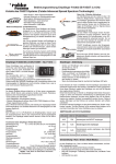
Instructions,
Telemetry-Box 2.4 GHz FASSTest®
No. F1666
Telemetry-Box 2.4 GHz FASSTest®
Contents
Please be sure to observe the Safety Notes.!
1.
Safety Notes...................................................... 2
2.
General Description.......................................... 3
3
Set Contents...................................................... 3
4.
Specification...................................................... 3
5.
Controls............................................................. 4
6
Mounting the Telemetry-Box on the transmitter.5
7.
Switching the Telemetry-Box on........................ 6
8.
Charging the Telemetry-Box.............................. 6
9.
Binding the Telemetry-Box to the transmitter.... 7
10.
Menu Structure / Description of Navigation....... 8
11.
Explanation, Telemetry display.......................... 9
12.
Explanation, Speech Output display............... 10
13.
Explanation, Volume display........................... 10
14.
14.1
14.2
14.3
14.4
14.5
14.6
Programming menu, main display................... 11
Speech menu.................................................. 11
Display menu................................................... 11
Sensor Set-up menu....................................... 12
Sensor Register menu.................................... 14
Model Select menu......................................... 15
Language Select menu................................... 16
15.
USB PC Port................................................... 16
16.
Recommended Accessories........................... 17
17.
USB Driver installation for Telemetry-Box...... 18
18.
robbe Telemetry-Box Update.......................... 20
19.
Service Centre Addresses.............................. 22
2
1.
!
Safety Notes
20.
Guarantee....................................................... 23
• Avoid kinking the aerial cable.
21.
Disposal of Old Equipment............................. 23
22.
Conformity Declaration.................................... 24
• The device is designed to be recharged from a USB
port only. Never charge it using a different voltage.
• Never attempt to charge the device using the S.Bus
socket, as this could ruin it.
• The Telemetry-Box switches itself off automatically
when the battery voltage falls to 3.3 V. If this should
happen, you must still switch the Telemetry-Box off
using the switch on the back of the unit.
Please check the battery voltage before every flight.
• It is essential to protect the device from dust, soiling and
damp.
• Avoid subjecting the unit to shock and pressure, and do
not expose it to severe vibration.
Telemetry-Box 2.4 GHz FASSTest®
2. General Description
Data output is generated via:
• A large, backlit screen
• Sound output via beeper or earphone
• Speech output via loudspeaker or earphone, in
German and English
3.
1x
1x
1x
1x
1x
Set Contents
Telemetry-Box FASSTest®
Mounting adapter for hand-held transmitter
Mounting adapter for console transmitter
Mini-USB lead
CD with instructions and driver software
4.
Specification
Frequency band:................................. 2.4–2.4835 GHz
Transmission system:..................... FASST/ FASSTest®
Channel spacing:........................................... 2048 kHz
Operating voltage:.................................. 3.7 V (1 LiPo)
Current drain:..................................................... 80 mA
Dimensions:................................. 92 x 54.5 x 20.5 mm
Weight: ................................................................. 76 g
• Vibration alarm
The device features an internal LiPo battery as power
supply, which is recharged using the USB charge lead
supplied in the set.
The device can be updated by the user himself at any
time via the integral USB port.
The sensor configuration process is carried out using the
S.BUS socket.
The set includes adapters for attaching the TelemetryBox to a hand-held or console-type transmitter.
The Telemetry-Box can pick up the signals from any receiver with integral telemetry transmitter.
For example, from R7008SB and R6308SBT receivers.
The Telemetry-Box is suitable both for upgrading existing
FASST systems to telemetry (R6308SBT required at the
model end), and also as a parallel display and output device for callers and co-pilots in the case of
FASSTest® telemetry systems.
3
Telemetry-Box 2.4 GHz FASSTest®
5. Controls
LCD screen with backlighting
The Telemetry-Box features a range of facilities and connection options. These include a set of buttons for controlling the display, and for setting up and programming
sensors.
Buzzer / loudspeaker
"ESC" button
"ESC" button
- Use this button in programming mode to move
back to the previous menu.
- Briefly pressing the "ESC" button in display mode
activates speech output or the melody, or
switches off the sounds.
- A long press on the "ESC" button in Display mode resets
the Min. and Max. values.
"+" button
- The values are increased or switched on using the "+"
button.
- It is also used to move upwards in
programming mode.
"+" button
"-" button
"ENT." button
"LINK" button
Monitor LED
On / Off switch
"-" button
- The values are decreased or switched off using the "-"
button.
- It is also used to move downwards in
programming mode.
Special feature of the "+" and "-" buttons:
Holding both these buttons pressed in takes you from the
Display menu to the Programming menu.
"ENT." button
- This button is used to select menus and
activate parameters.
Mini-USB socket
- A long press on this button in the Display menu
takes you to the Volume setting.
Earphone socket
4
S-BUS2 socket
Telemetry-Box 2.4 GHz FASSTest®
6.
Mounting the Telemetry-Box
on the transmitter
The Telemetry-Box can be fixed to hand-held transmitters
with carry handle, such as the T8FG, or to console-type
transmitters with threaded aerial, such as the FX-30, using
the adapters included in the set.
Mounting on a console-type transmitter
with threaded aerial
Mounting on a hand-held transmitter
The adapter for console transmitters is mounted on the
ball-end of the aerial thread.
The adapter for hand-held transmitters is mounted on the
transmitter's carry handle.
This is the procedure:
This is the procedure:
• Screw the adapter to the threaded part of the aerial.
• Remove the two screws in the adapter, and separate
the two components.
• Adjust the position of the adapter so that the "robbe"
label is legible.
• If you wish to make fine adjustments, loosen the screw
on the back of the adapter. Adjust the adapter's position,
then tighten the screw again.
Additional adapters are also available:
Telemetry-Box aerial adapter,
26 mm
No. F1666100
• Now fit the Telemetry-Box on the two retaining pegs.
• Place the front and rear sections round the carry handle,
and re-assemble them.
• Now adjust the position of the adapter so that you can
easily read the screen.
• Tighten the two screws to fix the adapter in place.
• Now fit the Telemetry-Box on the two retaining pegs.
Adapter for mounting the
Telemetry-Box on the FC-18 transmitter.
Gooseneck for TelemetryBox
No. F1666200
Gooseneck for mounting the
Telemetry-Box on all transmitters
with option wells for switches, e.g.
FX-20.
Telemetry-Box
bayonet
adapter
No. F1666300
Adapter for mounting the
Telemetry-Box on all transmitters
with bayonet-fit aerial, e.g. T14MZ
and FX-40.
5
Telemetry-Box 2.4 GHz FASSTest®
7. Switching the Telemetry-Box on
8. Charging the Telemetry-Box
To switch the unit on, the micro-switch on the back of the
unit must be moved up to the "ON" position.
The Telemetry-Box is fitted with an internal 3.7 V / 500
mAh LiPo battery. The Telemetry-Box battery can be charged from any PC or USB charger using the mini-USB lead.
On / Off switch
When switched on, the screen displays the software version number and the actual Telemetry-Box voltage.
If you wish to charge the Telemetry-Box "on the road", use
a USB adapter for your car's cigarette lighter; USB adapters for domestic use are also available. Use only a USB
charger rated at 5 V / 1 A.
Note:
When the Telemetry-Box is connected to a PC, you may
see a window in which you are requested to install the software driver for the Telemetry-Box. However, this driver is
only needed if you wish to update the software, i.e. you
can ignore this message if you only wish to charge the
Telemetry-Box.
Safety Note:
The Telemetry-Box switches itself off automatically when
the battery voltage falls to 3.3 V. If this should happen, you
must still switch the Telemetry-Box off using the switch on
the back of the unit.
Please check the battery voltage before every flight.
6
Telemetry-Box 2.4 GHz FASSTest®
9. Binding the Telemetry-Box to the
transmitter
Basically the Telemetry-Box can be connected to R7008SB
and R6308SBT receivers.
To ensure that the Telemetry-Box can pick up data from the
receiver, the receiver must first be bound to the transmitter.
The method of binding is described in the instructions supplied with your transmitter and / or receiver.
Important:
The R6308SBT and R7008SB telemetry receivers only
transmit the telemetry data available to them if the receivers are bound to a FASST / FASSTest transmitter.
The purpose of this is to reduce background electrical interference and unnecessary frequency use of the 2.4 GHz
band.
Binding
• Ensure that the receiver in the model is bound to the
RC system transmitter.
Note:
The Telemetry-Box stores the last two binding processes.
When you switch models, this makes it possible to continue to use the Telemetry-Box without having to re-bind.
• Place the RC system receiver close to the TelemetryBox (approx. 10 cm).
• Now switch the Telemetry-Box on.
• Locate the "LINK/MODE" button on the telemetry
receiver and hold it pressed in for about five seconds;
this activates transmit mode on the telemetry receiver.
• The monitor LED on the receiver now flashes red and
green.
• The telemetry receiver is bound by holding the "LINK"
button on the Telemetry-Box pressed in for about three
seconds. The monitor LED flashes red and green.
„LINK“- Taste
Monitor LED
FASST steering channels
FASSTest Telemetry Data
• Now switch off the Telemetry-Box and the receiver in
order to save the binding information.
• When you switch on the receiver and the TelemetryBox again, the green LED on the Telemetry-Box lights
up to confirm the link between receiver and TelemetryBox.
7
Telemetry-Box 2.4 GHz FASSTest®
10. Menu Structure / Description of Navigation
Speech
output
displays
A:ACT MODEL0 SPH/ ON
RECEIVER-BATTERY
BA
A:ON MODEL0 SPH/ ON
RECEIVER-BATTERY
MIN:
10.0V
A:ACT MODEL0 SPH/ ON
RECIVER EXT.BATTERY
XT
A:ON MODEL0 SPH/ ON
RECIVER EXT.BATTERY
MIN:
70.0V
A:ACT MODEL0 SPH/ ON
VARIO-F1712
12 ALTITUDE
6.4V
Screen
displays
6.5V
PAUSE TIME
REPEAT
VOICE VOLUME
10 S
EIN
6
BUTTON VOLUME
LCD CONTRAST
LCD BACKLIGHT
3
0
10 S
A:ON MODEL0 SPH/ ON
VARIO-F1712 ALTITUDE
150m
MIN:
+2999m
A:ACT MODEL0 SPH/ ON
VARIO-F1712
12 VARIO
A:EIN MODEL0 SPH/ EIN
VARIO-F1712 VARIO
3.0m/s
MAX:
0.0m/s
RECEIVER
1 VARIO-F1712
3 VARIO-F1672
5 TEMP125-F1713
8 GPS-F1675
A:ON MODEL0 SPH/ ON
GPS-F1675 ALTITUDE
250m
Press
the ESC
button
MIN:
+2999m
A:ACT MODEL0 SPH/ ON
GPS-F1675 VARIO
V
MAX:
0m
A:ON MODEL0 SPH/ ON
GPS-F1675 VARIO
3.0m/s
MIN:
+50.0m/s
A:ACT MODEL0 SPH/ ON
TEMP125-F1713
TEMP.
17
MAX:
0.0m/s
A:ON MODEL0 SPH/ ON
TEMP125-F1713 TEMP.
50°C
MIN:
+999°C
A:ACT MODEL0 SPH/ ON
GPS-F1675 SPEED
S
MAX:
0°C
A:ON MODEL0 SPH/ ON
GPS-F1675 SPEED
100km/h
MIN:
+500km/h
A:ON MODEL0 SPH/ ON
D
GPS-F1675 DISTANCE
EIN
EIN
+10
4
+500
5
10S
REPEAT TIME:
FACTORY SET
2M
ALTITUDE SET
>VARIO SET
DISPLAY:
SPEECH:
SENSE:
MIN-VALUE:
SIGNAL TON:
MAX-VALUE:
SIGNAL-TON:
EIN
EIN
OFF
-3.0
6
+3.0
7
ALERT TIME:
REPEAT TIME:
FACTORY SET
10S
2M
push
+/- key
+
and
-
MODEL0 SPH/ ON
GPS-F1675 POSITION
North 00°00.0000
East 00°00.0000
STARTEN POSITION
North 00°00.0000
East 00°00.0000
2
2
1
8
DISPLAY:
SPEECH:
MIN-VALUE:
SIGNAL TON:
MAX-VALUE:
SIGNAL TON:
ALERT TIME:
EIN
EIN
+10
4
+500
5
10S
REPEAT TIME:
FACTORY SET
2M
DISPLAY:
SPEECH:
MAX-WERT:
SIGNAL TON:
ALERT TIME:
REPEAT TIME:
FACTORY SET
EIN
EIN
200
4
10S
2M
TEMPERATURE SET
ALTITUDE SET
VARIO SET
>SPEED SET
>DISTANCE SET
>POSITION SET
Shortcut functions:
• Short use of „Esc“ key activate the selected speech
output of this list.
• Long use of „Esc“ key reset the Min/Max memory and
set the altitude value to zero (0).
• Short use of „Ent“ key is global switching between
setting of Speech / Melody / Audio off.
• Long use of „+“ key is activating the speech output of
the actual display value:
1
2
3
4
5
6
7
VARIO-F1712
**RESERVED**
VARIO-F1672
**RESERVED**
TEMP125-F1713
FREE
FREE
1 2
3 2
5 1
SELECT MODEL TEST
OPEN MODEL
NEW MODEL
DELETE MODEL
A:ON MODEL0 SPH/ ON
GPS-F1675 DISTANCE
MAX:
0m
1
3
5
8
SPEECH
DISPLAY
SENSOR SETTING
REGIST. SENSOR
SELECT MODEL
LANGUAGE
MAX:
0km/h
150m
8
DISPLAY:
SPEECH:
MIN-VALUE:
SIGNAL TON:
MAX-VALUE:
SIGNAL TON:
ALERT TIME:
MAX:
0m
MIN:
+50.0m/s
A:ACT MODEL0 SPH/ ON
GPS-F1675 ALTITUDE
A
>ALTITUDE SET
VARIO SET
Hold the „ENT.“ button pressed in to move to the Set-up
menu. The screen display now looks like this.
+/- key adjust the volume
LANGUAGE
ENGLISCH
TYP: VARIO-F1712
>NUMBER:
START SLOT NUM:
USE SLOT NUM:
REMOVE SENSOR
1
1
2
OPEN MODEL TEST
>EDGE
ARCUS
ASW-28-3M
>SPRACHE
DEUTSCH
NEW MODEL
TEST
+,-./0123456789:
;(=)? ABCDEFGHIJ
KLMNOPQRSTUVWXYZ
----------------------MODEL NAME((+
))
DELETE MODEL TEST
>EDGE
ARCUS
ASW-28-3M
Telemetry-Box 2.4 GHz FASSTest®
11. Explanation, Telemetry Display
In its basic form the telemetry display is always the same; it
varies only according to the various sensors in use.
The "+" and "-" buttons are used to navigate through the
Display menu, as described in chapter 5.
In order to keep the list of displays short and comprehensible, only the values of the active sensors are displayed,
and in the corresponding sequence (see chapter 14.3 /
Display).
SPH/ ON: Speech output ON
If you select this option, speech output is activated only for
the sensor which has been selected in the "Speech Output" display (see page 10, chapter 12). The warnings for all
sensors are also generated in spoken form.
Example: "Receiver battery" display:
Alarm messages On / Off
The alarm is switched on for the sensor type shown on the
screen. This function can be altered under "Warning duration" in the "Sensor set-up" menu.
MEL/ ON: Vario melody On
If "MEL/ On" is activated, only the vario tone and the warning tones are shown.
Name of the active model memory
A:ON
Sensor type display
Minimum voltage value
EDGE SPH/ ON
RECEIVER BATTERY
6.4V
AUD/ OFF: Audio tones Off
If you set the "AUD/ OFF" function, warnings only are generated in spoken form; all other audio signals are switched off.
Voltage display in Volt
MIN:
10.0V
9
Telemetry-Box 2.4 GHz FASSTest®
12. Explanation, Speech Output display
13. Explanation, Volume display
In the Speech Output display you can set which sensor
data are to be generated in speech output form.
In its basic form this display is always the same; it only
varies by differences in the sensor names.
The volume of the speech output can be adjusted in the
Volume display.
The sequence of the displays may also vary, depending on
whether the sensors are switched on or off in the "SENSOR SETTING" menu under the "SPEECH" option.
Hold the "ENT." button pressed in to move to the Set-up
menu. The screen display now looks like this:
Hold the "ESC." button pressed in to move to the Speech
Output display. The screen display looks like this:
A:ON
MODEL0 RECEIVER BATTERY
SPH/ ON
The volume can now be changed using the "+" and "-" buttons.
The desired sensor for speech output can be selected
using the "+" and "-" buttons, as described in chapter 5.
Please note that only the data from one sensor can be generated as speech output. The other sensors, such as the
Vario, are then generated using the Melody function (see
page 9).
10
Note:
The Volume setting only applies to speech output; The volume of the button beep is not affected by any change you
make here.
Telemetry-Box 2.4 GHz FASSTest®
14. Main Screen programming menu
14.1 Speech menu
14.2 Display menu
Holding both the "+" and "-" buttons pressed in takes you
from the Display menu to the Programming menu.
In the "Speech" menu the parameters for speech output
can be adjusted:
In the "Display" menu you can adjust the parameters for
the screen display:
Pause:
Time adjustment for the interval between speech messages.
Adjustment range: 5-30 seconds.
Button beep:
Adjustment of button beep and warning sound volume.
Adjustment range: 0-7
>SPEECH
DISPLAY
SensorSetup
SensorRegister
ModelSelect
SpeechSelect
Repeat:
At this point you can set whether the speech message is to
be repeated or not.
Volume:
Volume setting for speech output and Vario tones. However, volume can also be altered from the Display menu. All
you have to do is hold the "ENT." button pressed in (see
page 10, chapter 13).
Adjustment range: 0-7
>Pause
Repeat
Volume
10 s
On
6
LCD contrast:
Adjustment of screen contrast.
Adjustment range: 0-10
LCD backlight:
Adjustment of screen backlight duration.
Adjustment range: 10-Unlim (always on) seconds
>Button beep3
LCD contrast
0
LCD backlight
10 s
11
Telemetry-Box 2.4 GHz FASSTest®
14.3 Sensor Setup menu
Explanation, "Sensor Setup" sub-menu
The "Sensor Setup" menu shows all registered sensors. It
is also possible to adjust various parameters for individual
sensors.
Explanation, "Sensor Setup" main menu
The main menu displays the channels which are in use by
one sensor type, in addition to the sensor name and the
start channel.
To move to the set-up sub-menu of a sensor, use the "-"
button to select the appropriate sensor, then press the
"ENT." button to confirm your choice.
For the Vario sensor the following screen display appears:
ALTITUDE SET
>VARIO SET
For example, two channels (altitude and vario) are reserved for a Vario sensor.
If multi-sensors are connected, e.g. the GPS multi-sensor,
eight channels are reserved for this sensor. The sensor
sequence can be set in the "Sensor Register" menu.
Start channel
Start channel
Channels in use by
sensor type
Sensor name
Receiver
>1 Vario
3 TEK Vario
5 Temp 125
8 GPS
1
3
5
8
2
2
1
8
Now you can use the "-" or "+" button to select the sensor
type for which the setting is to be made.
Briefly press the "ENT." button to accept the setting.
The following set-up sub-menu is shown with two screen
displays:
>DISPLAY:
Language:
Sensitivity:
MIN VALUE:
WarningTONE:
MAX VALUE:
WarningTONE:
ON
ON
HIGH
-3.0
6
+3.0
7
Display:
At the "Display" setting it is possible to program whether
the sensors are to appear in the list of screen displays or
not. For example, the desired sensors can be assembled
to form an individual display list.
Speech:
At this point it is possible to select whether the sensor is
to be included in the list of "Speech Output" displays (see
page 10, chapter 12). This enables you to select sensors
for which an optional speech output is to be generated.
This in turn improves the clarity of the speech output display.
Sensitivity:
This function is used to adjust the sensitivity of the sensor.
Note:
If you have registered multiple vario sensors, but only
use one, you should select the "OFF" setting for the
sensors not in use. If you do not do this, you may find
the display difficult to understand, as it will show two
vario values.
Adjustment range:
OFF: Sensor disabled
LOW: +- 0.2 - +- 8m/s (Vario setting)
HIGH: +- 0.05 - +- 2m/s (TEK vario setting.
If thermals are strong, switch to LOW)
Min Value:
At this point it is possible to select a minimum value, which
triggers an on-screen warning, the vibration alarm and an
audio alarm when it is reached.
Note:
The alarm can be switched off at any time using the "ESC"
button. If it is not switched off, it continues to sound for
the period of time defined under "WARNING DURATION"
(page 13).
Adjustment range: Sensor-specific
12
Telemetry-Box 2.4 GHz FASSTest®
WARNINGtone:
Here you can select a sound which provides an audible
warning that the MIN VALUE has been reached.
Adjustment range: 0 ... 29
>WARN DURATION:
RepeatTIME:
FACTORY SET:
10s
2m
Max Value:
At this point it is possible to select a maximum value, which
triggers an on-screen warning, the vibration alarm and an
audio alarm when it is reached.
Note:
The alarm can be switched off at any time using the "ESC"
button. If it is not switched off, it continues to sound for the
period of time defined under "WARNING DURATION".
Adjustment range: Sensor-specific
WarningDURATION:
The "WARNING DURATION" function is used to set how
long the signal tone for the minimum value (sink) and maximum value (climb) is to last.
Adjustment range: OFF ... 30s
WARNINGtone:
Here you can select a sound which provides an audible
warning that the MAX VALUE has been reached.
Adjustment range: 0 ... 29
RepeatTime:
If you wish a "Min." or "Max." value to persist even after the
set "WARNING DURATION", you can enter a time at this
point at which the signal tone for sink or climb is triggered
again.
Adjustment range: OFF ... 30s
Factory Set:
Holding the "ENT." button pressed in for about two seconds, resets all parameters.
13
Telemetry-Box 2.4 GHz FASSTest®
14.4 Sensor Register menu
Registering a sensor
The "Sensor Register" menu is used to register new sensors to the system, and to display sensors which are already registered.
• Connect a sensor to the S-BUS2, taking care to maintain
correct polarity (see illustration).
S.BUS 2
Explanation, "Sensor Register" main menu
The main menu displays the channels which are in use by
one sensor type, in addition to the sensor name and the
start channel.
For example, two channels (altimeter and vario) are reserved if a vario sensor is registered.
Start channel
Start channel
Sensor name
1
2
3
4
5
6
7
14
Vario-F1712
**Reserved**
VARIO-F1672
**Reserved**
Temp125-F1713
FREE
FREE
Channels in use
by sensor type
1 2
3 2
5 1
The following screen display now appears:
TYPE: VARIO
>NUMBER:1
START SLOT NUM:
1
NUMBER OF SLOTS:
2
Erase SENSOR
• A single press on the "ENT." button registers
the sensor.
• Now select the "Sensor Register" menu. The following
screen display now appears:
1
2
3
4
5
6
7
FREE
FREE
FREE
FREE
FREE
FREE
FREE
• A start channel must now be selected. Use the "=" and
"ENT." buttons for this.
1
1
2
3
4
5
6
7
FREE
FREE
FREE
FREE
FREE
FREE
FREE
FREE
Erasing a sensor
This is the procedure for erasing a sensor:
• Move to the "Sensor Register" menu.
• Use the "-" or "+" button to select the sensor to be erased,
and confirm your choice with the "ENT." button.
• The following screen display now appears:
TYPE: VARIO
NUMBER:1
START SLOT NUM:
1
NUMBER OF SLOTS:
2
>Erase SENSOR
• Now move the Select arrow to the
"ERASE sensor" function.
• Hold the "ENT." button pressed in for about two seconds to
erase the sensor.
Telemetry-Box 2.4 GHz FASSTest®
14.5 Model Select menu
Explanation, "OPEN MODEL" sub-menu
Explanation, "ERASE model" sub-menu
Data for up to ten different models can be stored in the
"Model Select" menu; they can then be activated when you
wish to fly the corresponding model.
When you open the menu, the screen display looks
like this:
When you open the menu, the screen display looks
like this:
OPEN MODEL
>EDGE
Arcus
ASW-28
MODEL ERASE
>EDGE
ARCUS
ASW-28
Explanation, "Model Select" main menu
Three sub-menus can be selected from the main menu:
• Open model (select model memory)
• New model
(create new model memory)
• Erase model (delete model memory)
EDGE
EDGE
Use the "-" / "+" buttons or the "ENT." button to select a
sub-menu.
Model Select
>Open model
New model
Erase model
Now you can select one of the model memories using the
"+" or "-" buttons. Press the "ENT." button to confirm your
choice.
Now you can select one of the model memories using the
"+" or "-" buttons. To erase the memory, confirm with the
"ENT." button.
Explanation, "NEW model" sub-menu
Press the "ESC." button to return to the main menu.
When you open the menu, the screen display looks
like this:
Note:
It is not possible to erase the current memory. If you wish
to erase it, first select a different model memory as the
active memory.
NEW MODEL
EDGE
+,-./0123456789:
;(=)? ABCDEFGHIJ
KLMNOPQRSTUVWXYZ
----------------------MODEL NAME((+
))
Now you can move the cursor over the letters and symbols
using the "-" button, then accept the desired character
with the "+" button. In this way you can set a name with
up to six characters. Press the "RNT." button to accept the
name. The name is now saved, and is displayed on the
screen at top right.
15
Telemetry-Box 2.4 GHz FASSTest®
14.6 Language Select menu
The screen language is selected in the "LanguageSELECT" menu.
Note:
The Telemetry-Box is shipped as standard with German as
screen language and German as speech output language.
If you set the language to "English", this will appear on the
screen, but the telemetry output is still generated in the
German language.
Always use only one language when operating the
Telemetry-Box (German = speech output - German =
display language).
Setting two languages (German - English) may result
in unwanted errors.
The software for English speech output is available on the
robbe website at:
http://www.robbe.de/telemetry-box-2-4-ghz-fasstestr.html
The following language settings are available:
• English
• German
>Language
16
German
15. USB PC socket
This is the procedure for selecting a language:
• Move to the "Language Select" menu.
• Press the "ENT." button.
• Now press the "=" or "+" button to change
the language.
• Press the "ESC." button to save the setting and
quit the menu.
The Telemetry-Box is fitted with a mini-USB port on the
left-hand side. The mini-USB lead can be plugged into
this socket for connection to a PC. Software updates can
be carried out using this lead.
Note:
A USB driver must be installed in order to carry out
an update or change of language. The driver, and the
"Robbe_Telemetry_Downloader" program, as well as the
English language file can be found on the robbe website
at:
http://www.robbe.de/telemetry-box-2-4-ghz-fasstestr.html
Telemetry-Box 2.4 GHz FASSTest®
16. Recommended accessories
Vario and altimeter (TEK)
No. F1672
Telemetry-Box aerial adapter,
No. F1666100
26 mm
Precision variometer with altitude
and variometer monitoring using
two separate pressure sensors.
Adapter for mounting the
Telemetry-Box on the FC-18 transmitter.
GPS Multi Sensor No. F1675
Gooseneck for TelemetryBox
No. F1666200
Multi-functional GPS vario / altitude / distance / position sensor for the FASSTest® telemetry
system.
Gooseneck for mounting the
Telemetry-Box on all transmitters
with option wells for switches, e.g.
FX-20.
Vario-Sensor No. F1712
Small, light, low-cost vario / altimeter for the FASSTest® telemetry system. back to the previous
menu. The sequence and display
unit are automatically configured
by the individual robbe-Futaba
sensor ID when the sensor is
registered (to the transmitter or to
the Telemetry-Box).
Telemetry-Box
bayonet
adapter
No. F1666300
Adapter for mounting the
Telemetry-Box on all transmitters
with bayonet-fit aerial, e.g. T14MZ
and FX-40.
Temperature sensor 125°C No. F1713
Temperature sensor 125°C, for
the FASSTest® telemetry system.
The sequence and display unit are
automatically configured by the
individual robbe-Futaba sensor ID
when the sensor is registered (to
the transmitter or to the TelemetryBox).
Temperature range: -20…+125°C
17
Telemetry-Box 2.4 GHz FASSTest®
17. USB driver installation for the Telemetry-Box
Note:
Note: The USB driver must be installed for the purpose of carrying out a software or speech update. The USB driver, and the "Robbe_Telemetry_Downloader" update
program, can be found on the robbe website at: http://www.robbe.de/telemetry-box-2-4-ghz-fasstestr.html
1. Start the file "CP210x_VCP_Win_XP_S2K3_Vista_7.exe". The following display
appears. Click on "NEXT".
3. Click on "NEXT".
2. Select "I accept the terms of the license agreement" and click on "NEXT".
4. Click on "INSTALL".
18
Telemetry-Box 2.4 GHz FASSTest®
5. This completes the driver installation. Select the "Launch the CP210x VCP Driver
Installer" field and click on "FINISH".
6. Click on "INSTALL". When the installation is complete, confirm
with "OK".
19
Telemetry-Box 2.4 GHz FASSTest®
18. robbe Telemetry-Box update
1. Connect the Telemetry-Box to the PC using the USB lead, and switch it on.
2. Start the file "Robbe_Telemetry_Downloader_V1.1". The following display appears.
4. Now you can determine under "Tools" whether a software update for the firmware (Firmware
Download) or speech output (Sound Data Download) of the Telemetry-Box is to be carried
out.
5. The various displays appear as follows:
3. Select "Port Select-Telemetry-Box" under "Config" in order to define the port on the PC to
which the Telemetry-Box is connected.
Firmware update display
( frm file)
Speech output update display
( snd file)
20
Telemetry-Box 2.4 GHz FASSTest®
6. To install the new software at this point, select the "Browse" field and mark the desired file.
Important note:
Ensure that you have also selected the correct file format; Firmware update = frm file /
Speech update = snd file. Installing the wrong file type could ruin the device.
The latest software updates can be found at http://www.robbe.de/telemetry-box-2-4-ghz-fasstestr.html.
To install the software, click on "Download". The following display appears:
Important note:
It is essential not to disconnect or switch off the device during the update procedure. In the worst case
this could ruin the device.
7. Close the field once the installation is successfully completed.
8. After installation, switch the Telemetry-Box off and remove the USB lead. The new software can now be used.
21
Telemetry-Box 2.4 GHz FASSTest®
19. Service Centre addresses
Country
Company
Street
City
Telephone
Fax
E-mail
Andorra
Sorteny
Santa Anna, 13
AND-00130 Les escaldesPrincip. D‘Andorre
00376-862 865
00376-825 476
sorteny@sorteny.com
Denmark
Nordic Hobby A/S
Bogensevej 13
DK-8940 Randers SV
0045-86-43 61 00
0045-86-43 77 44
hobby@nordichobby.com
Germany
robbe-Service
Metzloser Str.38
D-36355 Grebenhain
0049-6644-87-777
0049-6644-87-779 hotline@robbe.com
England
robbe-Schlüter UK
Newton Road, Hinckley
GB-LE10 3DS Leicestershire
0044-1455-637151
0044-1455-635151 keith@robbeuk.co.uk
France
S.A.V Messe
6, Rue Usson du Poitou,
BP 12
F-57730 Folschviller
0033 3 87 94 62 58
0033-3-87 94 62 58 sav-robbe@wanadoo.fr
Greece
TAG Models Hellas
18,Vriullon Street
GR-14341 New Philadelfia/
Athens
0030-2-102584380
0030-2-102533533 info@tagmodels.gr
Italy
MC-Electronic
Via del Progresso, 25
I-36010 Cavazzale
di Monticello C.Otto (Vi)
0039 0444 945992
0039 0444 945991 mcelec@libero.it
Netherlands / Belg.
Jan van Mouwerik
Slot de Houvelaan 30
NL-3155 Maasland
0031-10-59 13 594
0031-10-59 13 594
van_Mouwerik@versatel.
nl
Norway
Norwegian Modellers
Box 2140
N-3103 Toensberg
0047-333 78 000
0047-333 78 001
per@modellers.com
Österreich
robbe-Service
Puchgasse 1
A-1220 Vienna
0043-1259-66-52
0043-1258-11-79
office@robbe.at
Sweden
Minicars Hobby A.B.
Bergsbrunnagatan 18
S-75323 Uppsala
0046-186 06 571
0046-186 06 579
info@minicars.se
Switzerland
robbe Futaba Service
Hinterer Schürmattweg 25 CH-4203 Grellingen
0041 61 741 23 22
info@robbefutaba-service.ch
Slovakian Rep.
Ivo Marhoun
Horova 9
CZ-35201 AS
00420 351 120 162
ivm2000@seznam.cz
Spain
robbe-Service
Metzloser Str. 38
D-36355 Grebenhain
0049-6644-87-777
Czech Republic
Ivo Marhoun
Horova 9
CZ-35201 AS
00420 351 120 162
22
0049-6644-87-779 hotline@robbe.com
ivm2000@seznam.cz
Telemetry-Box 2.4 GHz FASSTest®
20. Guarantee
Naturally all our products are guaranteed for 24 months
as required by law. If you wish to make a justified claim
under guarantee, please contact your dealer in the first
instance, as he is responsible for the guarantee and for
processing guarantee claims.
During the guarantee period we will rectify any functional
defects, production faults or material flaws at no cost to
you. We will not accept any further claims, e.g. for consequential damage.
Goods must be sent to us with carriage pre-paid; we will
pay return carriage costs. We will not accept any packages sent without pre-paid postage.
We accept no liability for transport damage, nor for the
loss of your shipment. We recommend that you take out
appropriate insurance.
Send your device to the approved Service Centre in your
country.
The following requirements must be fulfilled before
we can process your guarantee claim:
• You must include proof of purchase (till receipt) with
the returned product.
• You must have operated the product in accordance
with the operating instructions.
• You must have used recommended power sources
and genuine robbe accessories exclusively.
• There must be no damage present caused by moisture, unauthorised intervention, polarity reversal, overloading and mechanical stress.
• Please include a concise, accurate description of the
fault to help us locate the problem.
Liability exclusion
This battery charger is designed and approved solely for the purpose of charging the batteries defined
in the operating instructions. robbe Modellsport
accepts no liability whatsoever if the charger has
been used for any purpose other than the intended
one.
robbe Modellsport is unable to ensure that you observe
the assembly and operating instructions, or the conditions and methods employed for installing, operating and
maintaining the radio control system components.
For this reason we accept no liability for loss, damage or
costs which are due to the erroneous use and operation
of our products, or are connected with such operation in
any way.
Regardless of the legal argument employed, our obligation to pay compensation is limited to the invoice value
of those robbe products directly involved in the event in
which the damage occurred, unless otherwise prescribed
by law. This does not apply if the company is deemed to
have unlimited liability according to statutory regulation
due to deliberate or gross negligence.
21. Disposal of Old Equipment
Electronic equipment should not simply be discarded in
the normal household waste: that is the meaning of the
symbol shown here on the product. This
symbol means that you should dispose of
electrical and electronic equipment separately from the household waste at the end of
its useful life. Take the device to your local
communal collection point or recycling centre. This applies to countries of the European Union as
well as other European countries with separate collection
systems.
Dear Customer, you have purchased a battery
/ battery-powered product from us. The battery
lasts a very long time, but at some time you will
need to dispose of it. Exhausted batteries must
not be discarded in the domestic waste.
The user is obliged by law to take exhausted batteries to
the appropriate collection point. Old batteries contain valuable raw materials that can be recycled. The environment
and robbe are grateful to you for your efforts.
The meaning of the waste bin:
Batteries must not be discarded in the domestic waste.
The symbols below the waste bins mean:
Pb: Battery contains Lead
Cd: Battery contains Cadmium
Hg: Battery contains Mercury
Note: (applicable in Germany only)
On 1 October 1998, a new Battery Regulation came into
force, which regulates the return and disposal of used /
exhausted batteries. This regulation creates an obligation
to return, recycle and dispose of all types of battery. We
comply with this regulation by participating in the Common
Battery Return System (GRS - Batteries), which provides
for the return and disposal of every type of battery. You,
dear customer, can return your batteries to the following
collection points for disposal at no charge to you.
• Communal collection points
• At your dealer
• At any retail outlet (regardless of where the battery was
originally purchased).
23
Telemetry-Box 2.4 GHz FASSTest®
22. Conformity Declaration
robbe Modellsport GmbH & Co. KG hereby declares that
this device conforms to the fundamental requirements
and other relevant regulations of the corresponding EC
Directive. Under www.robbe.com, you will find the original
Conformity Declaration by clicking on the Logo button
"Conform" shown together with the appropriate device
description.
robbe Modellsport GmbH & Co. KG
Metzloser Strasse 38
Telephone +49 (0) 6644 / 87-0
D-36355 Grebenhain OT Metzlos/Gehaag
robbe Form AHBC
www.robbe.com
hotline@robbe.com
24
Errors and technical modifications reserved.
Copyright robbe-Modellsport 2012
Duplication and copying of the text, in whole or in part,
is only permitted with the prior written approval of robbeModellsport GmbH & Co. KG